EP3542727A1 - Articulation mechanisms for tissue specimen retrieval devices and tissue specimen retrieval devices incorporating the same - Google Patents
Articulation mechanisms for tissue specimen retrieval devices and tissue specimen retrieval devices incorporating the same Download PDFInfo
- Publication number
- EP3542727A1 EP3542727A1 EP19164532.4A EP19164532A EP3542727A1 EP 3542727 A1 EP3542727 A1 EP 3542727A1 EP 19164532 A EP19164532 A EP 19164532A EP 3542727 A1 EP3542727 A1 EP 3542727A1
- Authority
- EP
- European Patent Office
- Prior art keywords
- end effector
- effector assembly
- tissue specimen
- articulation block
- articulation
- Prior art date
- Legal status (The legal status is an assumption and is not a legal conclusion. Google has not performed a legal analysis and makes no representation as to the accuracy of the status listed.)
- Granted
Links
- 0 *CCC1C2=CC*CC12 Chemical compound *CCC1C2=CC*CC12 0.000 description 1
Images


Classifications
-
- A—HUMAN NECESSITIES
- A61—MEDICAL OR VETERINARY SCIENCE; HYGIENE
- A61B—DIAGNOSIS; SURGERY; IDENTIFICATION
- A61B17/00—Surgical instruments, devices or methods
- A61B17/00234—Surgical instruments, devices or methods for minimally invasive surgery
-
- A—HUMAN NECESSITIES
- A61—MEDICAL OR VETERINARY SCIENCE; HYGIENE
- A61B—DIAGNOSIS; SURGERY; IDENTIFICATION
- A61B17/00—Surgical instruments, devices or methods
- A61B17/22—Implements for squeezing-off ulcers or the like on inner organs of the body; Implements for scraping-out cavities of body organs, e.g. bones; for invasive removal or destruction of calculus using mechanical vibrations; for removing obstructions in blood vessels, not otherwise provided for
- A61B17/221—Gripping devices in the form of loops or baskets for gripping calculi or similar types of obstructions
-
- A—HUMAN NECESSITIES
- A61—MEDICAL OR VETERINARY SCIENCE; HYGIENE
- A61B—DIAGNOSIS; SURGERY; IDENTIFICATION
- A61B17/00—Surgical instruments, devices or methods
- A61B17/00234—Surgical instruments, devices or methods for minimally invasive surgery
- A61B2017/00287—Bags for minimally invasive surgery
-
- A—HUMAN NECESSITIES
- A61—MEDICAL OR VETERINARY SCIENCE; HYGIENE
- A61B—DIAGNOSIS; SURGERY; IDENTIFICATION
- A61B17/00—Surgical instruments, devices or methods
- A61B17/00234—Surgical instruments, devices or methods for minimally invasive surgery
- A61B2017/00292—Surgical instruments, devices or methods for minimally invasive surgery mounted on or guided by flexible, e.g. catheter-like, means
- A61B2017/00336—Surgical instruments, devices or methods for minimally invasive surgery mounted on or guided by flexible, e.g. catheter-like, means with a protective sleeve, e.g. retractable or slidable
-
- A—HUMAN NECESSITIES
- A61—MEDICAL OR VETERINARY SCIENCE; HYGIENE
- A61B—DIAGNOSIS; SURGERY; IDENTIFICATION
- A61B17/00—Surgical instruments, devices or methods
- A61B17/22—Implements for squeezing-off ulcers or the like on inner organs of the body; Implements for scraping-out cavities of body organs, e.g. bones; for invasive removal or destruction of calculus using mechanical vibrations; for removing obstructions in blood vessels, not otherwise provided for
- A61B17/22031—Gripping instruments, e.g. forceps, for removing or smashing calculi
- A61B2017/22034—Gripping instruments, e.g. forceps, for removing or smashing calculi for gripping the obstruction or the tissue part from inside
-
- A—HUMAN NECESSITIES
- A61—MEDICAL OR VETERINARY SCIENCE; HYGIENE
- A61B—DIAGNOSIS; SURGERY; IDENTIFICATION
- A61B17/00—Surgical instruments, devices or methods
- A61B17/28—Surgical forceps
- A61B17/29—Forceps for use in minimally invasive surgery
- A61B2017/2926—Details of heads or jaws
- A61B2017/2927—Details of heads or jaws the angular position of the head being adjustable with respect to the shaft
Definitions
- the present disclosure relates to tissue specimen retrieval from an internal body cavity and, more particularly, to articulation mechanisms for tissue specimen retrieval devices and tissue specimen retrieval devices incorporating the same to facilitate retrieval of a tissue specimen from the internal body cavity.
- the entrance openings may be natural passageways of the body or may be surgically created, for example, by making a small incision into which a cannula is inserted.
- Minimally-invasive surgical procedures may be used for partial or total retrieval of a tissue specimen from an internal body cavity.
- the restricted access provided by minimally-invasive openings presents challenges with respect to maneuverability and visualization.
- the restricted access also presents challenges when the tissue specimen is required to be removed. As such, a tissue specimen that is deemed too large for intact retrieval may be broken down into a plurality of smaller pieces to facilitate retrieval from the internal body cavity.
- tissue specimen is required to be removed.
- retrieval of the tissue specimen in an enclosed environment is highly desirable to inhibit seeding of cancer cells.
- a tissue specimen retrieval device including a housing, an outer shaft extending distally from the housing and defining a longitudinal axis, an end effector assembly extending distally from the outer shaft in a deployed position of the end effector assembly, an actuator operably associated with the housing, and an articulation mechanism operably coupled between the actuator and the end effector assembly.
- the articulation mechanism includes an articulation block supporting the end effector assembly thereon and rotatable between a first orientation and a second orientation to thereby articulate the end effector assembly between an aligned position and an articulated position.
- the articulation mechanism further includes a spring operably associated with the articulation block and configured to bias the articulation block towards the second orientation, and an actuation sleeve slidable relative to the articulation block, in response to actuation of the actuator, from an engaged position, wherein the actuation sleeve is disposed about the articulation block to thereby retain the articulation block in the first orientation, to a disengaged position, wherein the actuation sleeve is positioned proximally of the articulation block such that the articulation block rotates to the second orientation under the bias of the spring to thereby articulate the end effector assembly from the aligned position to the articulated position.
- the articulation block in the first orientation, defines a first operable dimension less than a diameter of the actuation sleeve to permit receipt of the articulation block within the actuation sleeve and, in the second orientation, the articulation block defines a second operable dimension greater than the diameter of the actuation sleeve to inhibit return of the articulation block into the actuation sleeve.
- the actuation sleeve is further movable from the disengaged position to a locked position, wherein the actuation sleeve is moved to abut the second operable dimension of the articulation block, thereby locking the end effector assembly in the articulated position or a further articulated position.
- the articulation block is pivotable about a pivot pin.
- the spring may be a torsion spring disposed about the pivot pin.
- the end effector assembly includes first and second arms configured to support a tissue specimen bag thereon.
- the end effector assembly is deployable relative to the outer shaft from a retracted position, wherein the end effector assembly is disposed within the outer shaft, to the deployed position.
- Another actuator may be provided and operably associated with the housing to selectively deploy the end effector assembly from the retracted position to the extended position.
- tissue specimen retrieval device includes a housing, an outer shaft extending distally from the housing and defining a longitudinal axis, an end effector assembly movable relative to the outer shaft, an actuator operably associated with the housing, an inner shaft operably coupled to the actuator at a proximal end portion of the inner shaft and extending distally from the actuator through the housing and the outer shaft, and an articulation mechanism operably coupled between the inner shaft and the end effector assembly.
- the articulation mechanism includes an articulation block pivotably supported at a distal end portion of the inner shaft, supporting the end effector assembly thereon, and rotatable between a first orientation and a second orientation to thereby articulate the end effector assembly between an aligned position and an articulated position.
- a spring is operably associated with the articulation block and configured to bias the articulation block towards the second orientation.
- the inner shaft In response to actuation of the actuator, the inner shaft is moved from an un-actuated position to an actuated position to move the articulation block from a proximal position, wherein the end effector assembly is disposed in a retracted position within the outer shaft thereby retaining the articulation block in the first orientation against the bias of the spring, to a distal position, wherein the end effector assembly extends distally from the outer shaft to permit the articulation block to rotate to the second orientation under the bias of the spring to thereby articulate the end effector assembly from the aligned position to the articulated position.
- the articulation block is pivotable relative to the inner shaft about a pivot pin.
- the spring may be a torsion spring disposed about the pivot pin.
- the end effector assembly includes first and second arms configured to support a tissue specimen bag thereon.
- an operable dimension of the first and second arms of the end effector assembly inhibit articulation of the end effector assembly within the outer shaft in the retracted position.
- the actuator is slidable relative to the housing between the un-actuated position and the actuated position.
- tissue specimen retrieval device includes a housing, an outer shaft extending distally from the housing and defining a longitudinal axis, an end effector assembly extending distally from the outer shaft in a deployed position of the end effector assembly, an actuator operably associated with the housing, and an articulation mechanism operably coupled between the actuator and the end effector assembly.
- the articulation mechanism includes an articulation block supporting the end effector assembly thereon and rotatable about a pivot.
- First and second actuation bars are coupled to the articulation block on respective first and second sides of the pivot at respective distal end portions thereof and to the actuator at respective proximal end portions thereof.
- Actuation of the actuator from an un-actuated position to a first actuated position moves the first actuation bar in a proximal direction and the second actuation bar in a distal direction to thereby rotate the articulation block such that the end effector assembly is articulated in a first direction from an aligned position to a first articulated position.
- Actuation of the actuator from the un-actuated position to a second actuated position moves the first actuation bar in the distal direction and the second actuation bar in the proximal direction to thereby rotate the articulation block such that the end effector assembly is articulated in a second, opposite direction from the aligned position to a second articulated position.
- the actuator is actuated in one direction from the un-actuated position to the first actuated position and in an opposite direction from the un-actuated position to the second actuated position.
- the actuator is movable about a second pivot between the un-actuated position and the first and second actuated positions, and the first actuation bar is coupled to the actuator on a first side of the second pivot with the second actuation bar coupled to the actuator on a second, opposite side of the second pivot.
- the end effector assembly includes first and second arms configured to support a tissue specimen bag thereon.
- the end effector assembly is deployable relative to the outer shaft from a retracted position, wherein the end effector assembly is disposed within the outer shaft, to the deployed position.
- another actuator is operably associated with the housing and configured to selectively deploy the end effector assembly from the retracted position to the extended position.
- the actuator is translatable to deploy the end effector assembly and rotatable to articulate the end effector assembly.
- the present disclosure provides articulation mechanisms for tissue specimen retrieval devices and tissue specimen retrieval devices incorporating the same to facilitate retrieval of tissue from the internal body cavity.
- Tissue specimen retrieval device 100 includes a housing 110, first and second actuators 120, 130 operably associated with housing 110, an outer shaft 140 extending distally from housing 110, an end effector assembly 150 selectively deployable from the distal end of outer shaft 140, and an articulation mechanism 180 configured to enable selective articulation of end effector assembly 150 relative to outer shaft 140 in the deployed position of end effector assembly 150.
- Housing 110 may define any suitable configuration to facilitate grasping and manipulating tissue specimen retrieval device 100 such as, for example, a pencil-grip configuration, a pistol-grip configuration, etc., and may include any suitable features to enhance ergonomics such as, for example, recesses, protrusions, textured surfaces, finger rings, etc.
- First actuator 120 is operably associated with housing 110 and coupled to outer shaft 140 to enable selective extension and retraction of outer shaft 140 relative to housing 110 and, thus, end effector assembly 150, to selectively move end effector assembly 150 between a retracted position ( FIG. 1 ) and a deployed position ( FIG. 2 ) relative to outer shaft 140 in response to actuation of first actuator 120.
- first actuator 120 may be coupled to end effector assembly 150 to enable selective extension and retraction of end effector assembly 150 relative to housing 110 and, thus, outer shaft 140, to similarly move end effector assembly 150 between a retracted position ( FIG. 1 ) and a deployed position ( FIG. 2 ) relative to outer shaft 140.
- First actuator 120 may be configured as a sliding actuator slidable along housing 110, as illustrated, or may define any other suitable configuration such as, for example, a plunger actuator that is selectively manipulatable relative to housing 110 along a longitudinal axis of housing 110, a pivoting actuator pivotable relative to housing 110, etc.
- Second actuator 130 is operably associated with housing 110 and coupled to articulation mechanism 180 ( FIGS. 4A-4D ) to enable selective articulation of end effector assembly 150 relative to outer shaft 140, once deployed from outer shaft 140, between an aligned position ( FIG. 2 ) and an articulated position ( FIG. 3 ), in response to actuation of second actuator 130.
- Second actuator 130 may be configured as a plunger actuator that is selectively manipulatable relative to housing 110 along a longitudinal axis of housing 110, as illustrated, or may define any other suitable configuration such as, for example, a pivoting actuator pivotable relative to housing 110, a sliding actuator slidable along housing 110, etc.
- outer shaft 140 extends distally from housing 110, as noted above, and is configured for insertion through an access cannula "C" ( FIG. 7 ) or natural passageway into an internal body cavity "B" ( FIG. 7 ).
- Outer shaft 140 may be substantially rigid (within manufacturing tolerances and in response to reasonable loads applied thereto) or may include one or more portions configured to flex and/or articulate relative to a longitudinal axis thereof.
- a lumen 142 extends longitudinally through outer shaft 140.
- Outer shaft 140 is slidable relative to housing 110 and end effector assembly 150 to enable selective deployment of end effector assembly 150 from outer shaft 140.
- outer shaft 140 is movable between a distal position, corresponding to the retracted position of end effector assembly 150 (see FIG. 1 ), wherein end effector assembly 150 is disposed within lumen 142 of outer shaft 140, and a proximal position, corresponding to the deployed position of end effector assembly 150 ( FIG. 2 ), wherein end effector assembly 150 extends distally from outer shaft 140.
- end effector assembly 150 may be selectively movable relative to housing 110 and outer shaft 140 to enable deployment of end effector assembly 150 from outer shaft 140 from the retracted position ( FIG. 1 ) to the deployed position ( FIG. 2 ).
- End effector assembly 150 includes a pair of arms 152, 154 and a tissue specimen bag 160 depending from arms 152, 154.
- Arms 152, 154 are configured for positioning within one or more channels 152, 154 formed about at least a portion of open end 166 of tissue specimen bag 160 to retain tissue specimen bag 160 on arms 152, 154.
- arms 152, 154 may be resiliently flexed inwardly to enable accommodation of arms 152, 154 within lumen 142 of outer shaft 140.
- Tissue specimen bag 160 may be furled, folded, or otherwise positioned in the retracted position of end effector assembly 150 to enable accommodation of tissue specimen bag 160 within lumen 142 of outer shaft 140.
- arms 152, 154 Upon deployment of end effector assembly 150 form outer shaft 140, arms 152, 154 are configured to resiliently return to a spaced-apart, curved configuration for retaining tissue specimen bag 160 thereon in an open condition, thus enabling insertion of a tissue specimen "T" ( FIG. 7 ) through open end 166 of tissue specimen bag 160 and into the interior thereof.
- the resilient return of arms 152, 154 may also serve to unfold, unfurl, or otherwise manipulate tissue specimen bag 160 upon deployment from outer shaft 140.
- Tissue specimen bag 160 may be formed from any suitable bio-compatible material (or materials), e.g., ripstop nylon, configured to retain a tissue specimen "T" ( FIG. 7 ) therein. As noted above, tissue specimen bag 160 depends from arms 152, 154 in the deployed position of end effector assembly 150 such that articulation of arms 152, 154 likewise articulates tissue specimen bag 160. Tissue specimen bag 160 defines at least one opening, e.g., at open end 166 thereof, and includes one or more channels 162, 164 formed about open end 166 thereof for receipt of arms 162, 146, respectively, therein.
- suitable bio-compatible material or materials
- Tissue specimen bag 160 defines at least one opening, e.g., at open end 166 thereof, and includes one or more channels 162, 164 formed about open end 166 thereof for receipt of arms 162, 146, respectively, therein.
- the one or more channels 162, 164 may be separate or in communication with one another, and/or may extend about only a portion of open end 166 of tissue specimen bag 160 or about the entirety perimeter thereof.
- Tissue specimen bag 160 may be disengaged from arms 152, 154 upon cinching closed open end 166 of tissue specimen bag 160, retraction of end effector assembly 150 back towards the retracted position ( FIG. 1 ), using a separate instrument, e.g., grasping device, and/or in any other suitable manner.
- an inner shaft 170 extends through outer shaft 140 and pivotably supports end effector assembly 150 at a distal end portion of inner shaft 170 via a pivot pin 172 and an articulation block 182 of articulation mechanism 180.
- inner shaft 170 is longitudinally fixed to housing 110 at a proximal end portion of inner shaft 170.
- inner shaft 170 is operably coupled to first actuator 120 at a proximal end portion of inner shaft 170 to enable movement of inner shaft 170 relative to housing 110 in response to actuation of first actuator 120.
- a rotation knob (not shown) associated with housing 110 and operably coupled to end effector assembly 150, e.g., via inner shaft 170, may be provided to enable selective rotation of end effector assembly 150 about the longitudinal axis of outer shaft 140 and relative to housing 110.
- articulation mechanism 180 operably couples second actuator 130 with arms 152, 154 of end effector assembly 150 to enable selective articulation of end effector assembly 150 (and, thus, tissue specimen bag 160 ( FIGS. 2 and 3 )) relative to outer shaft 140 when end effector assembly 150 is disposed in the deployed position ( FIGS. 2 and 3 ).
- Articulation mechanism 180 includes an articulation block 182, a torsion spring 184, and an actuation sleeve 186 that is slidably disposed within outer shaft 140 and about inner shaft 170.
- Articulation block 182 is pivotably coupled to inner shaft 170 via pivot pin 172 and supports proximal ends of arms 152, 154 of end effector assembly 150 thereon such that rotation of articulation block 182 about pivot pin 172 articulates arms 152, 154 relative to outer shaft 140.
- articulation block 182 in one second orientation, is aligned on the longitudinal axis of outer shaft 140 such that articulation block 182 rotates 90 degrees between the first and second orientations, although additional or alternative second orientation angles, e.g., 45 degrees, 60 degrees, etc., are also contemplated.
- articulation block 182 may define any other suitable shape having at least two dimensions wherein one of the dimensions is greater than the diameter of actuation sleeve 186 and the other of the dimensions is less than the diameter of actuation sleeve 186.
- Torsion spring 184 is disposed about pivot pin 172 and coupled to articulation block 182 to bias articulation block 182 towards the second orientation, wherein the width of articulation block 182 inhibits the return of articulation block 182 into actuation sleeve 186.
- Articulation block 182 is initially disposed within actuation sleeve 186 such that articulation block 182 is maintained in the first orientation against the bias of torsion spring 184.
- Actuation sleeve 186 is slidably disposed within outer shaft 140 and about inner shaft 170.
- Actuation sleeve 186 is coupled to second actuator 130 at a proximal end portion of actuation sleeve 186 such that actuation of second actuator 130 translates actuation sleeve 186 between an engaged position ( FIG. 4B ), wherein actuation sleeve 186 is disposed at least partially about articulation block 182 to maintain articulation block 182 in the first orientation against the bias of torsion spring 184, and a disengaged position ( FIG.
- actuation sleeve 186 is proximally-spaced from articulation block 182 to enable articulation block 182 to rotate to the at least one second orientation under the bias of torsion spring 184.
- Actuation sleeve 186 may further be moved from the disengaged position ( FIG. 4C ) to a locked position ( FIG. 4D ), wherein actuation sleeve 186 abuts articulation block 182, thereby locking articulation block 182 in one of the second orientations by inhibiting return thereof towards the first orientation.
- the second orientation corresponding to the disengaged position ( FIG. 4C ) may be the same as the second orientation corresponding to the locked position ( FIG.
- actuation sleeve 186 urges articulation block 182 to rotate further before abutting articulation block 182 in the locked position ( FIG. 4D ) such that the second orientation corresponding to the disengaged position ( FIG. 4C ) is different from the second orientation corresponding to the locked position ( FIG. 4D ), e.g., 45 degrees and 90 degrees, respectively, from the first orientation.
- end effector assembly 150 is initially disposed in the retracted position to facilitate insertion of tissue specimen retrieval device 100 through an access cannula "C" ( FIG. 7 ) or natural passageway into an internal body cavity "B" ( FIG. 7 ).
- actuation sleeve 186 is initially disposed in the engaged position, wherein actuation sleeve 186 is disposed at least partially about articulation block 182 to maintain articulation block 182 in the first orientation against the bias of torsion spring 184.
- end effector assembly 150 is deployed from outer shaft 140 by actuating first actuator 120 from a more-distal position to a more-proximal position to thereby withdraw outer shaft 140 proximally from about end effector assembly 150 such that end effector assembly 150 is deployed to the deployed positon.
- end effector assembly 150 remains aligned on the longitudinal axis of outer shaft 140 and actuation sleeve 186 remains disposed in the engaged position.
- second actuator 130 is moved proximally from a closer position relative to housing 110 to a further proximally-spaced position relative to housing 110 to thereby slide actuation sleeve 186 proximally about and relative to end effector assembly 150 and articulation block 182 from the engaged position ( FIG. 4B ) to the disengaged position ( FIG.
- articulation block 182 once no longer constrained by actuation sleeve 186, may be configured to move, under the bias of torsion spring 184, to any suitable articulated position relative to outer shaft 140 such as, for example, a 45 degree articulated positon, 60 degree articulated position, or a 90 degree articulated position, to similarly articulate end effector assembly 150 relative to outer shaft 140.
- end effector assembly 150 With actuation sleeve 186 disposed in the disengaged position ( FIG. 4C ), end effector assembly 150 is disposed in an articulated position relative to outer shaft 140 but may be urged back towards alignment with the longitudinal axis of outer shaft 140 or may be articulated further off of the longitudinal axis of outer shaft 140, e.g., in response to sufficient force on end effector assembly 150 to overcome the biasing force of torsion spring 184.
- second actuator 130 is returned proximally towards the closer position relative to housing 110 to thereby return actuation sleeve 186 distally relative to articulation block 182.
- actuation sleeve 186 is moved to a locked position wherein actuation sleeve 186 abuts articulation block 182.
- actuation sleeve 186 may abut articulation block 182 to maintain articulation block 182 in the same second orientation, or may further urge articulation block 182 to rotate before locking articulation block 182 in a further articulated second orientation. In either configuration, locking is achieved because, with articulation block 182 disposed in one of the second orientations, articulation block 182 is inhibited from passing into actuation sleeve 186. Rather, actuation sleeve 186 abuts articulation block 182 on either side of pivot pin 172 to inhibit pivoting of articulation block 182 from the second orientation, thereby locking end effector assembly 150 in the articulated positon.
- end effector assembly 150 of tissue specimen retrieval device 100 facilitates orientation of open end 166 of tissue specimen bag 160 in an appropriate position within the internal body cavity "B" to facilitate positioning of a tissue specimen "T" therein.
- End effector assembly 150 may be returned to the retracted position, which also serves to return end effector assembly 150 to the aligned position, by actuating first actuator 120 from the more-proximal position to the more-distal position to advance outer shaft 140 about end effector assembly 150. As such, end effector assembly 150 is moved to the aligned position and returned to the retracted positon to facilitate retrieval of end effector assembly 150 from the internal body cavity "B.”
- Tissue specimen retrieval device 200 includes a housing 210, an actuator 230 operably associated with housing 210, an outer shaft 240 extending distally from housing 210, an end effector assembly 250 selectively deployable from the distal end of outer shaft 240, and an articulation mechanism 280 configured to enable selective articulation of end effector assembly 250 relative to outer shaft 240.
- Tissue specimen retrieval device 200 is similar to tissue specimen retrieval device 100 ( FIGS. 1-4D and 7 ) and may include any of the features thereof, except as specifically contradicted below.
- Actuator 230 of tissue specimen retrieval device 200 is operably associated with housing 210 and coupled to articulation mechanism 280 to enable both selective movement of end effector assembly 250 between a retracted position and a deployed position ( FIG. 5B ) relative to outer shaft 240, and to articulate end effector assembly 250 relative to outer shaft 240 upon deployment of end effector assembly 250 from outer shaft 240.
- Actuator 230 may be configured as a plunger actuator that is selectively manipulatable relative to housing 210 along a longitudinal axis of housing 210, as illustrated, or may define any other suitable configuration.
- Outer shaft 240 is fixed relative to and extends distally from housing 210, while an inner shaft 270 extends through outer shaft 240 and pivotably supports end effector assembly 250 at a distal end portion of inner shaft 270 via a pivot pin 272 and an articulation block 282 of articulation mechanism 280.
- Inner shaft 270 is operably coupled to actuator 230 at a proximal end portion of inner shaft 270 to enable movement of inner shaft 270 relative to housing 210 and through outer shaft 240 in response to actuation of actuator 230.
- actuator 230 distally from a further proximally-spaced position relative to housing 110 to a closer position relative to housing 110 moves inner shaft 270 distally through outer shaft 240 to move end effector assembly 250 to the deployed position, wherein end effector assembly 250 extends distally from outer shaft 240.
- Articulation mechanism 280 operably couples actuator 230 with arms 252, 254 of end effector assembly 250 and includes an articulation block 282 and a torsion spring 284.
- Articulation block 282 is pivotably coupled to inner shaft 270 via pivot pin 272 and supports proximal ends of arms 252, 254 of end effector assembly 250 thereon such that rotation of articulation block 282 about pivot pin 272 articulates arms 252, 254 relative to outer shaft 240.
- Articulation block 282 is rotatable about pivot pin 272 between a first orientation, corresponding to an aligned position of end effector assembly 250 relative to a longitudinal axis of outer shaft 240, and a second orientation, corresponding to an articulated position of end effector assembly 250 relative to the longitudinal axis of outer shaft 240.
- articulation block 282 rotates 90 degrees between the first and second orientations, although other suitable rotation angles, e.g., 45 degrees, 60 degrees, etc., are also contemplated.
- Torsion spring 284 is disposed about pivot pin 272 and coupled to articulation block 282 to bias articulation block 282 towards the second orientation.
- articulation block 282 Prior to deployment of end effector assembly 250, articulation block 282 is disposed within outer shaft 240, wherein arms 252, 254 of end effector assembly 250 are constrained in a substantially aligned position relative to the longitudinal axis of outer shaft 240 via outer shaft 240, thereby maintaining articulation block 282 in the first orientation against the bias of torsion spring 284.
- end effector assembly 250 is initially disposed in the retracted position to facilitate insertion of tissue specimen retrieval device 200 through an access cannula "C" ( FIG. 7 ) or natural passageway into an internal body cavity "B" ( FIG. 7 ).
- end effector assembly 250 is deployed from outer shaft 240 and articulated to the articulated position by actuating actuator 230 distally from the further proximally-spaced position relative to housing 210 to the closer position relative to housing 210.
- articulation block 282 As end effector assembly 250 is no longer constrained by outer tube 240, articulation block 282, under the bias of torsion spring 284, rotates about pivot pin 272 to the second orientation, to similarly articulate end effector assembly 250 relative to outer shaft 240 to any suitable articulated position relative to outer shaft 240 such as, for example, a 90 degree articulated positon.
- actuator 230 In order to return end effector assembly 250 to the retracted position, actuator 230 is returned proximally from the closer position relative to housing 210 to the further proximally-spaced position relative to housing 210.
- Tissue specimen retrieval device 300 includes a housing 310, first and second actuators 320, 330 operably associated with housing 310, an outer shaft 340 extending distally from housing 310, an end effector assembly 350 selectively deployable from the distal end of outer shaft 340, and an articulation mechanism 380 configured to enable selective articulation of end effector assembly 350 relative to outer shaft 340.
- Tissue specimen retrieval device 300 is similar to tissue specimen retrieval device 100 ( FIGS. 1-4D and 7 ) and may include any of the features thereof, except as specifically contradicted below.
- First actuator 320 is operably associated with housing 310 and coupled to outer shaft 340 to enable selective retraction and extension of outer shaft 340 relative to housing 310 and, thus, end effector assembly 350, to selectively move end effector assembly 350 between a retracted position and a deployed position relative to outer shaft 340 in response to actuation of first actuator 320, similarly as detailed above with respect to tissue specimen retrieval device 100 ( FIGS. 1-4D and 7 ).
- Second actuator 330 is operably associated with housing 310 and coupled to articulation mechanism 380 to enable selective articulation of end effector assembly 350 relative to outer shaft 340, once deployed from outer shaft 340, between an aligned position ( FIG. 6A ) and a plurality of articulated positions ( FIGS. 6B and 6C ), in response to actuation of second actuator 330.
- Second actuator 330 more specifically, is pivotably coupled to housing 310 about a pivot pin 332 and pivotable relative thereto from a neutral position ( FIG. 6A ) to a positive pivoted position ( FIG. 6B ) and a negative pivoted position ( FIG. 6C ) in order to articulate end effector assembly 350 from an aligned position ( FIG.
- An inner shaft 370 extends through outer shaft 340 and pivotably supports end effector assembly 350 at a distal end portion of inner shaft 370 via a pivot pin 372 and an articulation block 382 of articulation mechanism 380.
- Inner shaft 370 is fixed relative to housing 310 and outer shaft 340 is movable relative thereto to deploy and retract end effector assembly 350 or, in other embodiments, outer shaft 340 is fixed relative to housing 310 and inner shaft 370 is movable relative thereto to deploy and retract end effector assembly 350.
- first actuator 320 may be eliminated and inner shaft 370 couples second actuator 330 with second actuator 330 also being longitudinally movable relative to housing 310.
- longitudinal movement of second actuator 330 relative to housing 310 moves inner shaft 370 through outer shaft 340 to deploy and retract end effector assembly 350, while pivoting of second actuator 330 relative to housing 310, as noted above, articulates end effector assembly 350 relative to housing 310.
- articulation mechanism 380 operably couples second actuator 330 with arms 352 of end effector assembly 350 to enable selective articulation of end effector assembly 350 relative to outer shaft 340 when end effector assembly 350 is disposed in the deployed position.
- Articulation mechanism 380 includes an articulation block 382, a first actuation bar 386, and a second actuation bar 388.
- Articulation block 382 is pivotably coupled to inner shaft 370 via pivot pin 372 extending through a central portion 383 of articulation block 382 and supports proximal ends of arms 352 of end effector assembly 350 thereon such that rotation of articulation block 382 about pivot pin 372 articulates arms 352 relative to outer shaft 340.
- First actuation bar 386 is pivotably coupled at a distal end portion thereof to articulation block 382 on one side of central portion 383 (and, thus, on one side of pivot pin 372)
- second actuation bar 388 is pivotably coupled at a distal end portion thereof to articulation block 382 on the other side of central portion 383 (and, thus, on the other side of pivot pin 372).
- the proximal end portions of first and second actuation bars 386, 388, respectively, are coupled to second actuator 330 via pin and slot engagements 387, 389, respectively, on opposing sides of pivot pin 332.
- end effector assembly 350 is initially disposed in the retracted position to facilitate insertion of tissue specimen retrieval device 300 through an access cannula "C" ( FIG. 7 ) or natural passageway into an internal body cavity "B" ( FIG. 7 ).
- end effector assembly 350 is deployed from outer shaft 340 and articulated to a desired position by actuating first actuator 320 and second actuator 330, respectively.
- first actuator 320 is returned to its initial position.
Landscapes
- Health & Medical Sciences (AREA)
- Surgery (AREA)
- Life Sciences & Earth Sciences (AREA)
- Heart & Thoracic Surgery (AREA)
- Nuclear Medicine, Radiotherapy & Molecular Imaging (AREA)
- Engineering & Computer Science (AREA)
- Biomedical Technology (AREA)
- Medical Informatics (AREA)
- Molecular Biology (AREA)
- Animal Behavior & Ethology (AREA)
- General Health & Medical Sciences (AREA)
- Public Health (AREA)
- Veterinary Medicine (AREA)
- Vascular Medicine (AREA)
- Orthopedic Medicine & Surgery (AREA)
- Surgical Instruments (AREA)
Abstract
Description
- The present disclosure relates to tissue specimen retrieval from an internal body cavity and, more particularly, to articulation mechanisms for tissue specimen retrieval devices and tissue specimen retrieval devices incorporating the same to facilitate retrieval of a tissue specimen from the internal body cavity.
- In minimally-invasive surgical procedures, operations are carried out within an internal body cavity through small entrance openings in the body. The entrance openings may be natural passageways of the body or may be surgically created, for example, by making a small incision into which a cannula is inserted.
- Minimally-invasive surgical procedures may be used for partial or total retrieval of a tissue specimen from an internal body cavity. However, the restricted access provided by minimally-invasive openings (natural passageways and/or surgically created openings) presents challenges with respect to maneuverability and visualization. The restricted access also presents challenges when the tissue specimen is required to be removed. As such, a tissue specimen that is deemed too large for intact retrieval may be broken down into a plurality of smaller pieces to facilitate retrieval from the internal body cavity.
- During such minimally-invasive surgical procedures, it is common that a cyst, tumor, or other affected tissue specimen is required to be removed. In these and other procedures where cancerous tissue is required to be removed, retrieval of the tissue specimen in an enclosed environment is highly desirable to inhibit seeding of cancer cells. Thus, with respect to breaking down large tissue specimens for retrieval through minimally-invasive openings, there is the added challenge of doing so within an enclosed environment.
- The present disclosure provides articulation mechanisms for tissue specimen retrieval devices and tissue specimen retrieval devices incorporating the same to facilitate retrieval of the tissue specimen from the internal body cavity. These and other aspects and features of the present disclosure are detailed below. As used herein, the term "distal" refers to the portion that is described which is further from a user, while the term "proximal" refers to the portion that is being described which is closer to a user. Further, any or all of the aspects and features described herein, to the extent consistent, may be used in conjunction with any or all of the other aspects and features described herein.
- Provided in accordance with aspects of the present disclosure is a tissue specimen retrieval device including a housing, an outer shaft extending distally from the housing and defining a longitudinal axis, an end effector assembly extending distally from the outer shaft in a deployed position of the end effector assembly, an actuator operably associated with the housing, and an articulation mechanism operably coupled between the actuator and the end effector assembly. The articulation mechanism includes an articulation block supporting the end effector assembly thereon and rotatable between a first orientation and a second orientation to thereby articulate the end effector assembly between an aligned position and an articulated position. The articulation mechanism further includes a spring operably associated with the articulation block and configured to bias the articulation block towards the second orientation, and an actuation sleeve slidable relative to the articulation block, in response to actuation of the actuator, from an engaged position, wherein the actuation sleeve is disposed about the articulation block to thereby retain the articulation block in the first orientation, to a disengaged position, wherein the actuation sleeve is positioned proximally of the articulation block such that the articulation block rotates to the second orientation under the bias of the spring to thereby articulate the end effector assembly from the aligned position to the articulated position.
- In an aspect of the present disclosure, in the first orientation, the articulation block defines a first operable dimension less than a diameter of the actuation sleeve to permit receipt of the articulation block within the actuation sleeve and, in the second orientation, the articulation block defines a second operable dimension greater than the diameter of the actuation sleeve to inhibit return of the articulation block into the actuation sleeve.
- In another aspect of the present disclosure, the actuation sleeve is further movable from the disengaged position to a locked position, wherein the actuation sleeve is moved to abut the second operable dimension of the articulation block, thereby locking the end effector assembly in the articulated position or a further articulated position.
- In still another aspect of the present disclosure, the articulation block is pivotable about a pivot pin. In such aspects, the spring may be a torsion spring disposed about the pivot pin.
- In yet another aspect of the present disclosure, the end effector assembly includes first and second arms configured to support a tissue specimen bag thereon.
- In still yet another aspect of the present disclosure, the end effector assembly is deployable relative to the outer shaft from a retracted position, wherein the end effector assembly is disposed within the outer shaft, to the deployed position. Another actuator may be provided and operably associated with the housing to selectively deploy the end effector assembly from the retracted position to the extended position.
- Another tissue specimen retrieval device provided in accordance with aspects of the present disclosure includes a housing, an outer shaft extending distally from the housing and defining a longitudinal axis, an end effector assembly movable relative to the outer shaft, an actuator operably associated with the housing, an inner shaft operably coupled to the actuator at a proximal end portion of the inner shaft and extending distally from the actuator through the housing and the outer shaft, and an articulation mechanism operably coupled between the inner shaft and the end effector assembly. The articulation mechanism includes an articulation block pivotably supported at a distal end portion of the inner shaft, supporting the end effector assembly thereon, and rotatable between a first orientation and a second orientation to thereby articulate the end effector assembly between an aligned position and an articulated position. A spring is operably associated with the articulation block and configured to bias the articulation block towards the second orientation. In response to actuation of the actuator, the inner shaft is moved from an un-actuated position to an actuated position to move the articulation block from a proximal position, wherein the end effector assembly is disposed in a retracted position within the outer shaft thereby retaining the articulation block in the first orientation against the bias of the spring, to a distal position, wherein the end effector assembly extends distally from the outer shaft to permit the articulation block to rotate to the second orientation under the bias of the spring to thereby articulate the end effector assembly from the aligned position to the articulated position.
- In an aspect of the present disclosure, the articulation block is pivotable relative to the inner shaft about a pivot pin. In such aspects, the spring may be a torsion spring disposed about the pivot pin.
- In another aspect of the present disclosure, the end effector assembly includes first and second arms configured to support a tissue specimen bag thereon. In aspects, an operable dimension of the first and second arms of the end effector assembly inhibit articulation of the end effector assembly within the outer shaft in the retracted position.
- In still another aspect of the present disclosure, the actuator is slidable relative to the housing between the un-actuated position and the actuated position.
- Another tissue specimen retrieval device provided in accordance with aspects of the present disclosure includes a housing, an outer shaft extending distally from the housing and defining a longitudinal axis, an end effector assembly extending distally from the outer shaft in a deployed position of the end effector assembly, an actuator operably associated with the housing, and an articulation mechanism operably coupled between the actuator and the end effector assembly. The articulation mechanism includes an articulation block supporting the end effector assembly thereon and rotatable about a pivot. First and second actuation bars are coupled to the articulation block on respective first and second sides of the pivot at respective distal end portions thereof and to the actuator at respective proximal end portions thereof. Actuation of the actuator from an un-actuated position to a first actuated position moves the first actuation bar in a proximal direction and the second actuation bar in a distal direction to thereby rotate the articulation block such that the end effector assembly is articulated in a first direction from an aligned position to a first articulated position. Actuation of the actuator from the un-actuated position to a second actuated position moves the first actuation bar in the distal direction and the second actuation bar in the proximal direction to thereby rotate the articulation block such that the end effector assembly is articulated in a second, opposite direction from the aligned position to a second articulated position.
- In an aspect of the present disclosure, the actuator is actuated in one direction from the un-actuated position to the first actuated position and in an opposite direction from the un-actuated position to the second actuated position.
- In another aspect of the present disclosure, the actuator is movable about a second pivot between the un-actuated position and the first and second actuated positions, and the first actuation bar is coupled to the actuator on a first side of the second pivot with the second actuation bar coupled to the actuator on a second, opposite side of the second pivot.
- In yet another aspect of the present disclosure, the end effector assembly includes first and second arms configured to support a tissue specimen bag thereon.
- In still another aspect of the present disclosure, the end effector assembly is deployable relative to the outer shaft from a retracted position, wherein the end effector assembly is disposed within the outer shaft, to the deployed position.
- In still yet another aspect of the present disclosure, another actuator is operably associated with the housing and configured to selectively deploy the end effector assembly from the retracted position to the extended position.
- In another aspect of the present disclosure, the actuator is translatable to deploy the end effector assembly and rotatable to articulate the end effector assembly.
- The above and other aspects and features of the present disclosure will become more apparent in view of the following detailed description when taken in conjunction with the accompanying drawings wherein like reference numerals identify similar or identical elements:
-
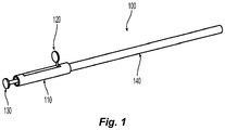
FIG. 1 is a side, perspective view of a tissue specimen retrieval device provided in accordance with aspects of the present disclosure, wherein an end effector assembly of the tissue specimen retrieval device is disposed in a retracted position; -
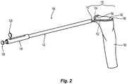
FIG. 2 is a side, perspective view of the tissue specimen retrieval device ofFIG. 1 , wherein the end effector assembly is disposed in a deployed, aligned position; -
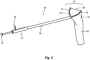
FIG. 3 is a side, perspective view of the tissue specimen retrieval device ofFIG. 1 , wherein the end effector assembly is disposed in a deployed, articulated position; -
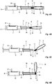
FIG. 4A is a side, partial cross-sectional view of the tissue specimen retrieval device ofFIG. 1 , with the specimen bag removed, and the end effector assembly disposed in the retracted positon; -
FIG. 4B is a side, partial cross-sectional view of the tissue specimen retrieval device ofFIG. 1 , with the specimen bag removed, and the end effector assembly disposed in the deployed, aligned positon; -
FIG. 4C is a side, partial cross-sectional view of the tissue specimen retrieval device ofFIG. 1 , with the specimen bag removed, and the end effector assembly disposed in the deployed, articulated position; -
FIG. 4D is a side, partial cross-sectional view of the tissue specimen retrieval device ofFIG. 1 , with the specimen bag removed, and the end effector assembly disposed in a deployed, further articulated, locked position; -
FIG. 5A is a side, partial cross-sectional view of another tissue specimen retrieval device provided in accordance with aspects of the present disclosure, with the specimen bag removed, and the end effector assembly disposed in a partially-deployed, aligned position; -
FIG. 5B is a side, partial cross-sectional view of the tissue specimen retrieval device ofFIG. 6A , with the specimen bag removed, and the end effector assembly disposed in a deployed, articulated position; -
FIG. 6A is a side, partial cross-sectional view of another tissue specimen retrieval device provided in accordance with aspects of the present disclosure, with the specimen bag removed, and the end effector assembly disposed in a deployed, aligned position; -
FIG. 6B is a side, partial cross-sectional view of the tissue specimen retrieval device ofFIG. 6A , with the specimen bag removed, and the end effector assembly disposed in a deployed, first articulated position; -
FIG. 6C is a side, partial cross-sectional view of the tissue specimen retrieval device ofFIG. 6A , with the specimen bag removed, and the end effector assembly disposed in a deployed, second articulated position; and -
FIG. 7 is a perspective view of the tissue specimen retrieval device ofFIG. 1 inserted through an access cannula into an internal body cavity for retrieval of a tissue specimen therefrom. - The present disclosure provides articulation mechanisms for tissue specimen retrieval devices and tissue specimen retrieval devices incorporating the same to facilitate retrieval of tissue from the internal body cavity.
- Turning to
FIGS. 1-4 A-D , a tissue specimen retrieval device provided in accordance with the present disclosure is shown generally identified byreference numeral 100. Tissuespecimen retrieval device 100 includes ahousing 110, first andsecond actuators housing 110, anouter shaft 140 extending distally fromhousing 110, anend effector assembly 150 selectively deployable from the distal end ofouter shaft 140, and anarticulation mechanism 180 configured to enable selective articulation ofend effector assembly 150 relative toouter shaft 140 in the deployed position ofend effector assembly 150. -
Housing 110, although illustrated as defining a generally tubular configuration, may define any suitable configuration to facilitate grasping and manipulating tissuespecimen retrieval device 100 such as, for example, a pencil-grip configuration, a pistol-grip configuration, etc., and may include any suitable features to enhance ergonomics such as, for example, recesses, protrusions, textured surfaces, finger rings, etc. -
First actuator 120 is operably associated withhousing 110 and coupled toouter shaft 140 to enable selective extension and retraction ofouter shaft 140 relative tohousing 110 and, thus, endeffector assembly 150, to selectively moveend effector assembly 150 between a retracted position (FIG. 1 ) and a deployed position (FIG. 2 ) relative toouter shaft 140 in response to actuation offirst actuator 120. Alternatively,first actuator 120 may be coupled to endeffector assembly 150 to enable selective extension and retraction ofend effector assembly 150 relative tohousing 110 and, thus,outer shaft 140, to similarly moveend effector assembly 150 between a retracted position (FIG. 1 ) and a deployed position (FIG. 2 ) relative toouter shaft 140.First actuator 120 may be configured as a sliding actuator slidable alonghousing 110, as illustrated, or may define any other suitable configuration such as, for example, a plunger actuator that is selectively manipulatable relative tohousing 110 along a longitudinal axis ofhousing 110, a pivoting actuator pivotable relative tohousing 110, etc. -
Second actuator 130 is operably associated withhousing 110 and coupled to articulation mechanism 180 (FIGS. 4A-4D ) to enable selective articulation ofend effector assembly 150 relative toouter shaft 140, once deployed fromouter shaft 140, between an aligned position (FIG. 2 ) and an articulated position (FIG. 3 ), in response to actuation ofsecond actuator 130.Second actuator 130 may be configured as a plunger actuator that is selectively manipulatable relative tohousing 110 along a longitudinal axis ofhousing 110, as illustrated, or may define any other suitable configuration such as, for example, a pivoting actuator pivotable relative tohousing 110, a sliding actuator slidable alonghousing 110, etc. - Continuing with reference to
FIGS. 1-4 A-D ,outer shaft 140 extends distally fromhousing 110, as noted above, and is configured for insertion through an access cannula "C" (FIG. 7 ) or natural passageway into an internal body cavity "B" (FIG. 7 ).Outer shaft 140 may be substantially rigid (within manufacturing tolerances and in response to reasonable loads applied thereto) or may include one or more portions configured to flex and/or articulate relative to a longitudinal axis thereof. Alumen 142 extends longitudinally throughouter shaft 140.Outer shaft 140, as noted above, is slidable relative tohousing 110 and endeffector assembly 150 to enable selective deployment ofend effector assembly 150 fromouter shaft 140. More specifically,outer shaft 140 is movable between a distal position, corresponding to the retracted position of end effector assembly 150 (seeFIG. 1 ), whereinend effector assembly 150 is disposed withinlumen 142 ofouter shaft 140, and a proximal position, corresponding to the deployed position of end effector assembly 150 (FIG. 2 ), whereinend effector assembly 150 extends distally fromouter shaft 140. As an alternative toouter shaft 140 moving relative tohousing 110 to deployend effector assembly 150, as also noted above,end effector assembly 150 may be selectively movable relative tohousing 110 andouter shaft 140 to enable deployment ofend effector assembly 150 fromouter shaft 140 from the retracted position (FIG. 1 ) to the deployed position (FIG. 2 ). -
End effector assembly 150 includes a pair ofarms tissue specimen bag 160 depending fromarms Arms more channels open end 166 oftissue specimen bag 160 to retaintissue specimen bag 160 onarms end effector assembly 150,arms arms lumen 142 ofouter shaft 140.Tissue specimen bag 160 may be furled, folded, or otherwise positioned in the retracted position ofend effector assembly 150 to enable accommodation oftissue specimen bag 160 withinlumen 142 ofouter shaft 140. Upon deployment ofend effector assembly 150 formouter shaft 140,arms tissue specimen bag 160 thereon in an open condition, thus enabling insertion of a tissue specimen "T" (FIG. 7 ) throughopen end 166 oftissue specimen bag 160 and into the interior thereof. The resilient return ofarms tissue specimen bag 160 upon deployment fromouter shaft 140. -
Tissue specimen bag 160 may be formed from any suitable bio-compatible material (or materials), e.g., ripstop nylon, configured to retain a tissue specimen "T" (FIG. 7 ) therein. As noted above,tissue specimen bag 160 depends fromarms end effector assembly 150 such that articulation ofarms tissue specimen bag 160.Tissue specimen bag 160 defines at least one opening, e.g., atopen end 166 thereof, and includes one ormore channels open end 166 thereof for receipt ofarms 162, 146, respectively, therein. The one ormore channels open end 166 oftissue specimen bag 160 or about the entirety perimeter thereof. One or more of the openings oftissue specimen bag 160, e.g.,open end 166, may include a cinch cord (not shown) disposed thereabout to enable selective closure of the opening.Tissue specimen bag 160 may be disengaged fromarms open end 166 oftissue specimen bag 160, retraction ofend effector assembly 150 back towards the retracted position (FIG. 1 ), using a separate instrument, e.g., grasping device, and/or in any other suitable manner. - With reference to
FIGS. 4A-4D , aninner shaft 170 extends throughouter shaft 140 and pivotably supportsend effector assembly 150 at a distal end portion ofinner shaft 170 via apivot pin 172 and anarticulation block 182 ofarticulation mechanism 180. In embodiments, such as the illustrative embodiment, whereend effector assembly 150 is longitudinally fixed relative tohousing 110 andouter shaft 140 is movable relative to endeffector assembly 150 andhousing 110 to deployend effector assembly 150,inner shaft 170 is longitudinally fixed tohousing 110 at a proximal end portion ofinner shaft 170. In embodiments, on the other hand, whereouter shaft 140 is longitudinally fixed relative tohousing 110 and endeffector assembly 150 is movable relative toouter shaft 140 andhousing 110 to deployend effector assembly 150,inner shaft 170 is operably coupled tofirst actuator 120 at a proximal end portion ofinner shaft 170 to enable movement ofinner shaft 170 relative tohousing 110 in response to actuation offirst actuator 120. - In embodiments, a rotation knob (not shown) associated with
housing 110 and operably coupled to endeffector assembly 150, e.g., viainner shaft 170, may be provided to enable selective rotation ofend effector assembly 150 about the longitudinal axis ofouter shaft 140 and relative tohousing 110. - Referring to
FIGS. 4A-4D ,articulation mechanism 180 operably couplessecond actuator 130 witharms end effector assembly 150 to enable selective articulation of end effector assembly 150 (and, thus, tissue specimen bag 160 (FIGS. 2 and3 )) relative toouter shaft 140 whenend effector assembly 150 is disposed in the deployed position (FIGS. 2 and3 ).Articulation mechanism 180 includes anarticulation block 182, atorsion spring 184, and anactuation sleeve 186 that is slidably disposed withinouter shaft 140 and aboutinner shaft 170. -
Articulation block 182 is pivotably coupled toinner shaft 170 viapivot pin 172 and supports proximal ends ofarms end effector assembly 150 thereon such that rotation ofarticulation block 182 aboutpivot pin 172 articulatesarms outer shaft 140.Articulation block 182 defines a generally rectangular configuration having a length greater than a diameter ofactuation sleeve 186 and a width less than the diameter ofactuation sleeve 186 such that, in a first orientation, wherein the length ofarticulation block 182 is sufficiently aligned on the longitudinal axis ofouter shaft 140,articulation block 182 is capable of being received withinactuation sleeve 186 and such that, in at least one second orientation, wherein the length ofarticulation block 182 is sufficiently angled relative toactuation sleeve 186,articulation block 182 is inhibited from being received withinactuation sleeve 186. In embodiments, in one second orientation, the width ofarticulation block 182 is aligned on the longitudinal axis ofouter shaft 140 such thatarticulation block 182 rotates 90 degrees between the first and second orientations, although additional or alternative second orientation angles, e.g., 45 degrees, 60 degrees, etc., are also contemplated. In order to accommodate one or more second orientation positions, in embodiments,articulation block 182 may define any other suitable shape having at least two dimensions wherein one of the dimensions is greater than the diameter ofactuation sleeve 186 and the other of the dimensions is less than the diameter ofactuation sleeve 186. -
Torsion spring 184 is disposed aboutpivot pin 172 and coupled to articulation block 182 to biasarticulation block 182 towards the second orientation, wherein the width ofarticulation block 182 inhibits the return ofarticulation block 182 intoactuation sleeve 186.Articulation block 182 is initially disposed withinactuation sleeve 186 such thatarticulation block 182 is maintained in the first orientation against the bias oftorsion spring 184. -
Actuation sleeve 186, as mentioned above, is slidably disposed withinouter shaft 140 and aboutinner shaft 170.Actuation sleeve 186 is coupled tosecond actuator 130 at a proximal end portion ofactuation sleeve 186 such that actuation ofsecond actuator 130 translatesactuation sleeve 186 between an engaged position (FIG. 4B ), whereinactuation sleeve 186 is disposed at least partially aboutarticulation block 182 to maintainarticulation block 182 in the first orientation against the bias oftorsion spring 184, and a disengaged position (FIG. 4C ), whereinactuation sleeve 186 is proximally-spaced fromarticulation block 182 to enable articulation block 182 to rotate to the at least one second orientation under the bias oftorsion spring 184.Actuation sleeve 186 may further be moved from the disengaged position (FIG. 4C ) to a locked position (FIG. 4D ), whereinactuation sleeve 186 abutsarticulation block 182, thereby lockingarticulation block 182 in one of the second orientations by inhibiting return thereof towards the first orientation. The second orientation corresponding to the disengaged position (FIG. 4C ) may be the same as the second orientation corresponding to the locked position (FIG. 4D ), e.g., both 90 degrees from the first orientation, or may be different, wherein, upon movement to the locked position,actuation sleeve 186 urgesarticulation block 182 to rotate further before abuttingarticulation block 182 in the locked position (FIG. 4D ) such that the second orientation corresponding to the disengaged position (FIG. 4C ) is different from the second orientation corresponding to the locked position (FIG. 4D ), e.g., 45 degrees and 90 degrees, respectively, from the first orientation. - With reference to
FIGS. 1-4D and7 , and initially toFIGS. 1 and4A , in use,end effector assembly 150 is initially disposed in the retracted position to facilitate insertion of tissuespecimen retrieval device 100 through an access cannula "C" (FIG. 7 ) or natural passageway into an internal body cavity "B" (FIG. 7 ). Further,actuation sleeve 186 is initially disposed in the engaged position, whereinactuation sleeve 186 is disposed at least partially aboutarticulation block 182 to maintainarticulation block 182 in the first orientation against the bias oftorsion spring 184. - Once tissue
specimen retrieval device 100 is disposed within the internal body cavity "B" (FIG. 7 ) as desired, and with reference toFIGS. 2 and4B ,end effector assembly 150 is deployed fromouter shaft 140 by actuatingfirst actuator 120 from a more-distal position to a more-proximal position to thereby withdrawouter shaft 140 proximally from aboutend effector assembly 150 such thatend effector assembly 150 is deployed to the deployed positon. At this point,end effector assembly 150 remains aligned on the longitudinal axis ofouter shaft 140 andactuation sleeve 186 remains disposed in the engaged position. - Referring to
FIG. 4C , if it is desired to articulateend effector assembly 150 relative toouter shaft 140 afterend effector assembly 150 is deployed fromouter shaft 140,second actuator 130 is moved proximally from a closer position relative tohousing 110 to a further proximally-spaced position relative tohousing 110 to thereby slideactuation sleeve 186 proximally about and relative to endeffector assembly 150 and articulation block 182 from the engaged position (FIG. 4B ) to the disengaged position (FIG. 4C ), such thatactuation sleeve 186 is proximally-spaced fromarticulation block 182 to enable articulation block 182 to rotate to the second orientation under the bias oftorsion spring 184, thereby articulatingend effector assembly 150 relative toouter shaft 140. More specifically,articulation block 182, once no longer constrained byactuation sleeve 186, may be configured to move, under the bias oftorsion spring 184, to any suitable articulated position relative toouter shaft 140 such as, for example, a 45 degree articulated positon, 60 degree articulated position, or a 90 degree articulated position, to similarly articulateend effector assembly 150 relative toouter shaft 140. Withactuation sleeve 186 disposed in the disengaged position (FIG. 4C ),end effector assembly 150 is disposed in an articulated position relative toouter shaft 140 but may be urged back towards alignment with the longitudinal axis ofouter shaft 140 or may be articulated further off of the longitudinal axis ofouter shaft 140, e.g., in response to sufficient force onend effector assembly 150 to overcome the biasing force oftorsion spring 184. - With reference to
FIG. 4D , in order to lockend effector assembly 150 in an articulated position, e.g., the same or a different second orientation asend effector assembly 150 is positioned under the bias oftorsion spring 184,second actuator 130 is returned proximally towards the closer position relative tohousing 110 to thereby returnactuation sleeve 186 distally relative to articulation block 182. However, instead of receivingarticulation block 182 therein,actuation sleeve 186 is moved to a locked position whereinactuation sleeve 186 abutsarticulation block 182. As noted above,actuation sleeve 186 may abutarticulation block 182 to maintainarticulation block 182 in the same second orientation, or may further urgearticulation block 182 to rotate before lockingarticulation block 182 in a further articulated second orientation. In either configuration, locking is achieved because, witharticulation block 182 disposed in one of the second orientations,articulation block 182 is inhibited from passing intoactuation sleeve 186. Rather,actuation sleeve 186 abuts articulation block 182 on either side ofpivot pin 172 to inhibit pivoting of articulation block 182 from the second orientation, thereby lockingend effector assembly 150 in the articulated positon. - Turning momentarily to
FIG. 7 , the above-detailed articulation ofend effector assembly 150 of tissuespecimen retrieval device 100 facilitates orientation ofopen end 166 oftissue specimen bag 160 in an appropriate position within the internal body cavity "B" to facilitate positioning of a tissue specimen "T" therein. -
End effector assembly 150 may be returned to the retracted position, which also serves to returnend effector assembly 150 to the aligned position, by actuatingfirst actuator 120 from the more-proximal position to the more-distal position to advanceouter shaft 140 aboutend effector assembly 150. As such,end effector assembly 150 is moved to the aligned position and returned to the retracted positon to facilitate retrieval ofend effector assembly 150 from the internal body cavity "B." - Referring to
FIGS. 5A and 5B , another tissue specimen retrieval device provided in accordance with the present disclosure is shown generally identified byreference numeral 200. Tissuespecimen retrieval device 200 includes ahousing 210, anactuator 230 operably associated withhousing 210, anouter shaft 240 extending distally fromhousing 210, anend effector assembly 250 selectively deployable from the distal end ofouter shaft 240, and anarticulation mechanism 280 configured to enable selective articulation ofend effector assembly 250 relative toouter shaft 240. Tissuespecimen retrieval device 200 is similar to tissue specimen retrieval device 100 (FIGS. 1-4D and7 ) and may include any of the features thereof, except as specifically contradicted below. -
Actuator 230 of tissuespecimen retrieval device 200 is operably associated withhousing 210 and coupled toarticulation mechanism 280 to enable both selective movement ofend effector assembly 250 between a retracted position and a deployed position (FIG. 5B ) relative toouter shaft 240, and to articulateend effector assembly 250 relative toouter shaft 240 upon deployment ofend effector assembly 250 fromouter shaft 240.Actuator 230 may be configured as a plunger actuator that is selectively manipulatable relative tohousing 210 along a longitudinal axis ofhousing 210, as illustrated, or may define any other suitable configuration. -
Outer shaft 240 is fixed relative to and extends distally fromhousing 210, while aninner shaft 270 extends throughouter shaft 240 and pivotably supportsend effector assembly 250 at a distal end portion ofinner shaft 270 via apivot pin 272 and anarticulation block 282 ofarticulation mechanism 280.Inner shaft 270 is operably coupled toactuator 230 at a proximal end portion ofinner shaft 270 to enable movement ofinner shaft 270 relative tohousing 210 and throughouter shaft 240 in response to actuation ofactuator 230. More specifically, movement ofactuator 230 distally from a further proximally-spaced position relative tohousing 110 to a closer position relative tohousing 110 movesinner shaft 270 distally throughouter shaft 240 to moveend effector assembly 250 to the deployed position, whereinend effector assembly 250 extends distally fromouter shaft 240. -
Articulation mechanism 280 operably couples actuator 230 witharms end effector assembly 250 and includes anarticulation block 282 and atorsion spring 284.Articulation block 282 is pivotably coupled toinner shaft 270 viapivot pin 272 and supports proximal ends ofarms end effector assembly 250 thereon such that rotation ofarticulation block 282 aboutpivot pin 272 articulatesarms outer shaft 240.Articulation block 282 is rotatable aboutpivot pin 272 between a first orientation, corresponding to an aligned position ofend effector assembly 250 relative to a longitudinal axis ofouter shaft 240, and a second orientation, corresponding to an articulated position ofend effector assembly 250 relative to the longitudinal axis ofouter shaft 240. In embodiments,articulation block 282 rotates 90 degrees between the first and second orientations, although other suitable rotation angles, e.g., 45 degrees, 60 degrees, etc., are also contemplated. -
Torsion spring 284 is disposed aboutpivot pin 272 and coupled to articulation block 282 to biasarticulation block 282 towards the second orientation. Prior to deployment ofend effector assembly 250,articulation block 282 is disposed withinouter shaft 240, whereinarms end effector assembly 250 are constrained in a substantially aligned position relative to the longitudinal axis ofouter shaft 240 viaouter shaft 240, thereby maintainingarticulation block 282 in the first orientation against the bias oftorsion spring 284. - Continuing with reference to
FIGS. 5A and 5B , in use,end effector assembly 250 is initially disposed in the retracted position to facilitate insertion of tissuespecimen retrieval device 200 through an access cannula "C" (FIG. 7 ) or natural passageway into an internal body cavity "B" (FIG. 7 ). Once tissuespecimen retrieval device 200 is disposed within the internal body cavity "B" (FIG. 7 ) as desired,end effector assembly 250 is deployed fromouter shaft 240 and articulated to the articulated position by actuatingactuator 230 distally from the further proximally-spaced position relative tohousing 210 to the closer position relative tohousing 210. Asend effector assembly 250 is no longer constrained byouter tube 240,articulation block 282, under the bias oftorsion spring 284, rotates aboutpivot pin 272 to the second orientation, to similarly articulateend effector assembly 250 relative toouter shaft 240 to any suitable articulated position relative toouter shaft 240 such as, for example, a 90 degree articulated positon. In order to returnend effector assembly 250 to the retracted position,actuator 230 is returned proximally from the closer position relative tohousing 210 to the further proximally-spaced position relative tohousing 210. - Turning now to
FIGS. 6A-6C , another tissue specimen retrieval device provided in accordance with the present disclosure is shown generally identified byreference numeral 300. Tissuespecimen retrieval device 300 includes ahousing 310, first andsecond actuators housing 310, anouter shaft 340 extending distally fromhousing 310, anend effector assembly 350 selectively deployable from the distal end ofouter shaft 340, and anarticulation mechanism 380 configured to enable selective articulation ofend effector assembly 350 relative toouter shaft 340. Tissuespecimen retrieval device 300 is similar to tissue specimen retrieval device 100 (FIGS. 1-4D and7 ) and may include any of the features thereof, except as specifically contradicted below. -
First actuator 320 is operably associated withhousing 310 and coupled toouter shaft 340 to enable selective retraction and extension ofouter shaft 340 relative tohousing 310 and, thus, endeffector assembly 350, to selectively moveend effector assembly 350 between a retracted position and a deployed position relative toouter shaft 340 in response to actuation offirst actuator 320, similarly as detailed above with respect to tissue specimen retrieval device 100 (FIGS. 1-4D and7 ). -
Second actuator 330 is operably associated withhousing 310 and coupled toarticulation mechanism 380 to enable selective articulation ofend effector assembly 350 relative toouter shaft 340, once deployed fromouter shaft 340, between an aligned position (FIG. 6A ) and a plurality of articulated positions (FIGS. 6B and 6C ), in response to actuation ofsecond actuator 330.Second actuator 330, more specifically, is pivotably coupled tohousing 310 about apivot pin 332 and pivotable relative thereto from a neutral position (FIG. 6A ) to a positive pivoted position (FIG. 6B ) and a negative pivoted position (FIG. 6C ) in order to articulateend effector assembly 350 from an aligned position (FIG. 6A ) to a first articulated position (FIG. 6B ) and a second articulated positon (FIG. 6C ), respectively.Second actuator 330 may be configured as a tilting actuator, as illustrated, or may be configured as rotation knob rotatable about pivot pin 332 (wherein the positive and negative positions are rotational positions in opposite directions from a neutral position of the rotation knob). - An
inner shaft 370 extends throughouter shaft 340 and pivotably supportsend effector assembly 350 at a distal end portion ofinner shaft 370 via apivot pin 372 and anarticulation block 382 ofarticulation mechanism 380.Inner shaft 370 is fixed relative tohousing 310 andouter shaft 340 is movable relative thereto to deploy and retractend effector assembly 350 or, in other embodiments,outer shaft 340 is fixed relative tohousing 310 andinner shaft 370 is movable relative thereto to deploy and retractend effector assembly 350. In embodiments whereinner shaft 370 is movable,first actuator 320 may be eliminated andinner shaft 370 couples second actuator 330 withsecond actuator 330 also being longitudinally movable relative tohousing 310. In such embodiments, longitudinal movement ofsecond actuator 330 relative tohousing 310 movesinner shaft 370 throughouter shaft 340 to deploy and retractend effector assembly 350, while pivoting ofsecond actuator 330 relative tohousing 310, as noted above, articulatesend effector assembly 350 relative tohousing 310. - Continuing with reference to
FIGS. 6A-6C ,articulation mechanism 380 operably couplessecond actuator 330 witharms 352 ofend effector assembly 350 to enable selective articulation ofend effector assembly 350 relative toouter shaft 340 whenend effector assembly 350 is disposed in the deployed position.Articulation mechanism 380 includes anarticulation block 382, afirst actuation bar 386, and asecond actuation bar 388. -
Articulation block 382 is pivotably coupled toinner shaft 370 viapivot pin 372 extending through acentral portion 383 ofarticulation block 382 and supports proximal ends ofarms 352 ofend effector assembly 350 thereon such that rotation ofarticulation block 382 aboutpivot pin 372 articulatesarms 352 relative toouter shaft 340.First actuation bar 386 is pivotably coupled at a distal end portion thereof to articulation block 382 on one side of central portion 383 (and, thus, on one side of pivot pin 372), whilesecond actuation bar 388 is pivotably coupled at a distal end portion thereof to articulation block 382 on the other side of central portion 383 (and, thus, on the other side of pivot pin 372). The proximal end portions of first and second actuation bars 386, 388, respectively, are coupled tosecond actuator 330 via pin andslot engagements pivot pin 332. - As a result of the above-detailed configuration, pivoting of
second actuator 330 relative tohousing 310 from the neutral position (FIG. 6A ) to the positive pivoted position (FIG. 6B ) pullsfirst actuation bar 386 proximally and pushessecond actuation bar 388 distally, thereby urgingarticulation block 382 to rotate in a first direction, e.g., counter-clockwise from the orientation illustrated inFIGS. 6A-6C , thus articulatingend effector assembly 350 in a first direction off of the longitudinal axis ofouter shaft 340. On the other hand, pivoting ofsecond actuator 330 relative tohousing 310 from the neutral position (FIG. 6A ) to the negative pivoted position (FIG. 6C ) pushesfirst actuation bar 386 distally and pullssecond actuation bar 388 proximally, thereby urgingarticulation block 382 to rotate in a second, opposite direction, e.g., clockwise from the orientation illustrated inFIGS. 6A-6C , thus articulatingend effector assembly 350 in a second, opposite direction off of the longitudinal axis ofouter shaft 340. - In use,
end effector assembly 350 is initially disposed in the retracted position to facilitate insertion of tissuespecimen retrieval device 300 through an access cannula "C" (FIG. 7 ) or natural passageway into an internal body cavity "B" (FIG. 7 ). Once tissuespecimen retrieval device 300 is disposed within the internal body cavity "B" (FIG. 7 ) as desired,end effector assembly 350 is deployed fromouter shaft 340 and articulated to a desired position by actuatingfirst actuator 320 andsecond actuator 330, respectively. In order to returnend effector assembly 350 to the retracted position,first actuator 320 is returned to its initial position. - From the foregoing and with reference to the various drawings, those skilled in the art will appreciate that certain modifications can be made to the present disclosure without departing from the scope of the same. While several embodiments of the disclosure have been shown in the drawings, it is not intended that the disclosure be limited thereto, as it is intended that the disclosure be as broad in scope as the art will allow and that the specification be read likewise. Therefore, the above description should not be construed as limiting, but merely as exemplifications of particular embodiments. Those skilled in the art will envision other modifications within the scope and spirit of the claims appended hereto.
- The invention may be described by reference to the following numbered paragraphs:
- 1. A tissue specimen retrieval device, comprising:
- a housing;
- an outer shaft extending distally from the housing and defining a longitudinal axis;
- an end effector assembly extending distally from the outer shaft in a deployed position of the end effector assembly;
- an actuator operably associated with the housing; and
- an articulation mechanism operably coupled between the actuator and the end effector assembly, the articulation mechanism including:
- an articulation block supporting the end effector assembly thereon, the articulation block rotatable between a first orientation and a second orientation to thereby articulate the end effector assembly between an aligned position and an articulated position;
- a spring operably associated with the articulation block and configured to bias the articulation block towards the second orientation; and
- an actuation sleeve slidable relative to the articulation block, in response to actuation of the actuator, from an engaged position, wherein the actuation sleeve is disposed about the articulation block to thereby retain the articulation block in the first orientation, to a disengaged position, wherein the actuation sleeve is positioned proximally of the articulation block such that the articulation block rotates to the second orientation under the bias of the spring to thereby articulate the end effector assembly from the aligned position to the articulated position.
- 2. The tissue specimen retrieval device according to paragraph 1, wherein, in the first orientation, the articulation block defines a first operable dimension less than a diameter of the actuation sleeve to permit receipt of the articulation block within the actuation sleeve, and wherein, in the second orientation, the articulation block defines a second operable dimension greater than the diameter of the actuation sleeve to inhibit return of the articulation block into the actuation sleeve.
- 3. The tissue specimen retrieval device according to paragraph 2, wherein the actuation sleeve is further movable from the disengaged position to a locked position, wherein the actuation sleeve is moved to abut the second operable dimension of the articulation block, thereby locking the end effector assembly in the articulated position or a further articulated position.
- 4. The tissue specimen retrieval device according to paragraph 1, wherein the articulation block is pivotable about a pivot pin and wherein the spring is a torsion spring disposed about the pivot pin.
- 5. The tissue specimen retrieval device according to paragraph 1, wherein the end effector assembly includes first and second arms configured to support a tissue specimen bag thereon.
- 6. The tissue specimen retrieval device according to paragraph 1, wherein the end effector assembly is deployable relative to the outer shaft from a retracted position, wherein the end effector assembly is disposed within the outer shaft, to the deployed position.
- 7. The tissue specimen retrieval device according to paragraph 6, further comprising another actuator operably associated with the housing and configured to selectively deploy the end effector assembly from the retracted position to the extended position.
- 8. A tissue specimen retrieval device, comprising:
- a housing;
- an outer shaft extending distally from the housing and defining a longitudinal axis;
- an end effector assembly movable relative to the outer shaft;
- an actuator operably associated with the housing;
- an inner shaft operably coupled to the actuator at a proximal end portion of the inner shaft, the inner shaft extending distally from the actuator through the housing and the outer shaft; and
- an articulation mechanism operably coupled between the inner shaft and the end effector assembly, the articulation mechanism including:
- an articulation block pivotably supported at a distal end portion of the inner shaft and supporting the end effector assembly thereon, the articulation block rotatable between a first orientation and a second orientation to thereby articulate the end effector assembly between an aligned position and an articulated position; and
- a spring operably associated with the articulation block and configured to bias the articulation block towards the second orientation,
- wherein, in response to actuation of the actuator, the inner shaft is moved from an un-actuated position to an actuated position to move the articulation block from a proximal position, wherein the end effector assembly is disposed in a retracted position within the outer shaft thereby retaining the articulation block in the first orientation against the bias of the spring, to a distal position, wherein the end effector assembly extends distally from the outer shaft to permit the articulation block to rotate to the second orientation under the bias of the spring to thereby articulate the end effector assembly from the aligned position to the articulated position.
- 9. The tissue specimen retrieval device according to paragraph 8, wherein the articulation block is pivotable relative to the inner shaft about a pivot pin.
- 10. The tissue specimen retrieval device according to paragraph 9, wherein the spring is a torsion spring disposed about the pivot pin.
- 11. The tissue specimen retrieval device according to paragraph 8, wherein the end effector assembly includes first and second arms configured to support a tissue specimen bag thereon.
- 12. The tissue specimen retrieval device according to paragraph 11, wherein an operable dimension of the first and second arms of the end effector assembly inhibit articulation of the end effector assembly within the outer shaft in the retracted position.
- 13. The tissue specimen retrieval device according to paragraph 8, wherein the actuator is slidable relative to the housing between the un-actuated position and the actuated position.
Claims (13)
- A tissue specimen retrieval device, comprising:a housing;an outer shaft extending distally from the housing and defining a longitudinal axis;an end effector assembly extending distally from the outer shaft in a deployed position of the end effector assembly;an actuator operably associated with the housing; andan articulation mechanism operably coupled between the actuator and the end effector assembly, the articulation mechanism including:an articulation block supporting the end effector assembly thereon, the articulation block rotatable between a first orientation and a second orientation to thereby articulate the end effector assembly between an aligned position and an articulated position;a spring operably associated with the articulation block and configured to bias the articulation block towards the second orientation; andan actuation sleeve slidable relative to the articulation block, in response to actuation of the actuator, from an engaged position, wherein the actuation sleeve is disposed about the articulation block to thereby retain the articulation block in the first orientation, to a disengaged position, wherein the actuation sleeve is positioned proximally of the articulation block such that the articulation block rotates to the second orientation under the bias of the spring to thereby articulate the end effector assembly from the aligned position to the articulated position.
- The tissue specimen retrieval device according to claim 1, wherein, in the first orientation, the articulation block defines a first operable dimension less than a diameter of the actuation sleeve to permit receipt of the articulation block within the actuation sleeve, and wherein, in the second orientation, the articulation block defines a second operable dimension greater than the diameter of the actuation sleeve to inhibit return of the articulation block into the actuation sleeve.
- The tissue specimen retrieval device according to claim 2, wherein the actuation sleeve is further movable from the disengaged position to a locked position, wherein the actuation sleeve is moved to abut the second operable dimension of the articulation block, thereby locking the end effector assembly in the articulated position or a further articulated position.
- The tissue specimen retrieval device according to any one of claims 1, 2 or 3 wherein the articulation block is pivotable about a pivot pin and wherein the spring is a torsion spring disposed about the pivot pin.
- The tissue specimen retrieval device according to any one of claims 1,2, 3 or 4 , wherein the end effector assembly includes first and second arms configured to support a tissue specimen bag thereon.
- The tissue specimen retrieval device according to any one of the preceding claim , wherein the end effector assembly is deployable relative to the outer shaft from a retracted position, wherein the end effector assembly is disposed within the outer shaft, to the deployed position.
- The tissue specimen retrieval device according to claim 6, further comprising another actuator operably associated with the housing and configured to selectively deploy the end effector assembly from the retracted position to the extended position.
- A tissue specimen retrieval device, comprising:a housing;an outer shaft extending distally from the housing and defining a longitudinal axis;an end effector assembly movable relative to the outer shaft;an actuator operably associated with the housing;an inner shaft operably coupled to the actuator at a proximal end portion of the inner shaft, the inner shaft extending distally from the actuator through the housing and the outer shaft; andan articulation mechanism operably coupled between the inner shaft and the end effector assembly, the articulation mechanism including:an articulation block pivotably supported at a distal end portion of the inner shaft and supporting the end effector assembly thereon, the articulation block rotatable between a first orientation and a second orientation to thereby articulate the end effector assembly between an aligned position and an articulated position; anda spring operably associated with the articulation block and configured to bias the articulation block towards the second orientation,wherein, in response to actuation of the actuator, the inner shaft is moved from an un-actuated position to an actuated position to move the articulation block from a proximal position, wherein the end effector assembly is disposed in a retracted position within the outer shaft thereby retaining the articulation block in the first orientation against the bias of the spring, to a distal position, wherein the end effector assembly extends distally from the outer shaft to permit the articulation block to rotate to the second orientation under the bias of the spring to thereby articulate the end effector assembly from the aligned position to the articulated position.
- The tissue specimen retrieval device according to claim 8, wherein the articulation block is pivotable relative to the inner shaft about a pivot pin.
- The tissue specimen retrieval device according to claim 9, wherein the spring is a torsion spring disposed about the pivot pin.
- The tissue specimen retrieval device according to any one of claims 8, 9 or 10, wherein the end effector assembly includes first and second arms configured to support a tissue specimen bag thereon.
- The tissue specimen retrieval device according to claim 11, wherein an operable dimension of the first and second arms of the end effector assembly inhibit articulation of the end effector assembly within the outer shaft in the retracted position.
- The tissue specimen retrieval device according to any one of claims 8 to 12, wherein the actuator is slidable relative to the housing between the un-actuated position and the actuated position.
Applications Claiming Priority (1)
| Application Number | Priority Date | Filing Date | Title |
|---|---|---|---|
| US15/933,825 US10792057B2 (en) | 2018-03-23 | 2018-03-23 | Articulation mechanisms for tissue specimen retrieval devices and tissue specimen retrieval devices incorporating the same |
Publications (2)
| Publication Number | Publication Date |
|---|---|
| EP3542727A1 true EP3542727A1 (en) | 2019-09-25 |
| EP3542727B1 EP3542727B1 (en) | 2022-05-04 |
Family
ID=65904289
Family Applications (1)
| Application Number | Title | Priority Date | Filing Date |
|---|---|---|---|
| EP19164532.4A Active EP3542727B1 (en) | 2018-03-23 | 2019-03-22 | Tissue specimen retrieval devices incorporating an articulation mechanism |
Country Status (2)
| Country | Link |
|---|---|
| US (2) | US10792057B2 (en) |
| EP (1) | EP3542727B1 (en) |
Families Citing this family (5)
| Publication number | Priority date | Publication date | Assignee | Title |
|---|---|---|---|---|
| US10667805B1 (en) | 2019-05-17 | 2020-06-02 | Composite Surgical, LLC | Steerable suture retriever |
| US11154295B1 (en) | 2020-05-14 | 2021-10-26 | Composite Surgical, LLC | Steerable suture retriever |
| US10973512B1 (en) * | 2020-05-14 | 2021-04-13 | Composite Surgical, LLC | Steerable suture retriever |
| CN113425338B (en) * | 2021-07-28 | 2025-07-25 | 河北医科大学第二医院 | Object taking device and method for thoracoscopic lung resected specimen |
| US12446867B1 (en) | 2024-09-20 | 2025-10-21 | Kobex LLC | Specimen retrieval apparatus and methods |
Citations (8)
| Publication number | Priority date | Publication date | Assignee | Title |
|---|---|---|---|---|
| EP0557963A1 (en) * | 1992-02-24 | 1993-09-01 | United States Surgical Corporation | Resilient arm mesh deployer |
| WO1995009666A1 (en) * | 1993-10-01 | 1995-04-13 | Advanced Surgical, Inc. | Self-deploying isolation bag |
| US5441499A (en) * | 1993-07-14 | 1995-08-15 | Dekna Elektro-U. Medizinische Apparatebau Gesellschaft Mbh | Bipolar radio-frequency surgical instrument |
| US20030144672A1 (en) * | 2002-01-25 | 2003-07-31 | Gellman Barry N. | Apparatus and method for stone removal from a body |
| US20110087235A1 (en) * | 2009-10-09 | 2011-04-14 | Applied Medical Resources Corporation | Single incision laparoscopic tissue retrieval system |
| EP2583629A2 (en) * | 2011-10-19 | 2013-04-24 | Covidien LP | Surgical retrieval apparatus for thoracic procedures |
| DE202015008447U1 (en) * | 2015-12-08 | 2016-03-31 | Oscar R. Polo | Device for separating tissue with two oscillating loop blades |
| US20160256145A1 (en) * | 2008-10-23 | 2016-09-08 | Covidien Lp | Surgical retrieval apparatus |
Family Cites Families (104)
| Publication number | Priority date | Publication date | Assignee | Title |
|---|---|---|---|---|
| US6004330A (en) | 1989-08-16 | 1999-12-21 | Medtronic, Inc. | Device or apparatus for manipulating matter |
| US5643283A (en) | 1992-01-03 | 1997-07-01 | Younker; Marlin E. | Surgical pouch |
| US6350266B1 (en) | 1995-02-02 | 2002-02-26 | Scimed Life Systems, Inc. | Hybrid stone retrieval device |
| WO1996023446A1 (en) | 1995-02-02 | 1996-08-08 | Boston Scientific Corporation | Surgical wire basket extractor |
| US6264663B1 (en) | 1995-10-06 | 2001-07-24 | Metamorphic Surgical Devices, Llc | Device for removing solid objects from body canals, cavities and organs including an invertable basket |
| IT241710Y1 (en) | 1996-06-20 | 2001-05-17 | Fina Ernesto | DEVICE FOR ENDOCAVITARY ELECTROLYSIS OF URINE CALCULATIONS OELECTROLITOLYSIS |
| WO1999004704A2 (en) | 1997-07-24 | 1999-02-04 | Mcguckin James F Jr | Breast surgery method and apparatus |
| US6099534A (en) | 1997-10-01 | 2000-08-08 | Scimed Life Systems, Inc. | Releasable basket |
| US6530923B1 (en) | 1998-02-10 | 2003-03-11 | Artemis Medical, Inc. | Tissue removal methods and apparatus |
| US6344026B1 (en) | 1998-04-08 | 2002-02-05 | Senorx, Inc. | Tissue specimen encapsulation device and method thereof |
| US6659105B2 (en) | 1998-02-26 | 2003-12-09 | Senorx, Inc. | Tissue specimen isolating and damaging device and method |
| US6383195B1 (en) | 1998-04-13 | 2002-05-07 | Endoline, Inc. | Laparoscopic specimen removal apparatus |
| CA2294484C (en) | 1998-04-23 | 2004-03-30 | Scimed Life Systems, Inc. | Atraumatic medical retrieval device |
| JP2000037388A (en) | 1998-05-20 | 2000-02-08 | Osamu Yoshida | Organ storage bag and organ storage bag insert |
| US6206889B1 (en) | 1998-06-26 | 2001-03-27 | Roberto Bennardo | Device for removing anatomical parts by laparoscopy |
| US6162209A (en) | 1998-11-17 | 2000-12-19 | Scimed Life Systems, Inc. | Multi-function surgical instrument tool actuator assembly |
| US6387102B2 (en) | 1998-11-20 | 2002-05-14 | Ancel Surgical R&D, Inc. | Reusable laparoscopic retrieval mechanism |
| US6258102B1 (en) | 1998-11-20 | 2001-07-10 | Ancel Surgical R&D, Inc. | Reusable laproscopic retrieval mechanism |
| US6059793A (en) | 1998-11-20 | 2000-05-09 | Pagedas; Anthony C. | Reusable laproscopic retrieval mechanism and method for use |
| US6156055A (en) | 1999-03-23 | 2000-12-05 | Nitinol Medical Technologies Inc. | Gripping device for implanting, repositioning or extracting an object within a body vessel |
| US6358198B1 (en) | 1999-05-18 | 2002-03-19 | John M. Levin | Laparoscopic/thorascopic support device |
| US7169154B1 (en) | 1999-05-25 | 2007-01-30 | Scimedlife Systems, Inc. | Releasable basket and method of making thereof |
| WO2001001846A2 (en) | 1999-07-02 | 2001-01-11 | Clavius Devices Inc. | Device and method for removing large tissue masses |
| AUPQ254199A0 (en) | 1999-08-31 | 1999-09-23 | University Of Western Australia, The | Methods and devices for obtaining samples from hollow viscera |
| US6171317B1 (en) | 1999-09-14 | 2001-01-09 | Perclose, Inc. | Knot tying device and method |
| US6368328B1 (en) | 1999-09-16 | 2002-04-09 | Scimed Life Systems, Inc. | Laser-resistant medical retrieval device |
| US6228095B1 (en) | 1999-10-14 | 2001-05-08 | Core Dynamics, Inc. | Specimen retrieval device |
| US7285126B2 (en) | 2000-06-29 | 2007-10-23 | Concentric Medical, Inc. | Systems, methods and devices for removing obstructions from a blood vessel |
| US6406440B1 (en) | 2000-12-21 | 2002-06-18 | Ethicon Endo-Surgery, Inc. | Specimen retrieval bag |
| US6350267B1 (en) | 2000-12-21 | 2002-02-26 | Ethicon Endo-Surgery, Inc. | Method of use of an improved specimen retrieval bag |
| EP1294286B1 (en) | 2001-01-08 | 2005-12-07 | Boston Scientific Limited | Retrieval basket with releasable tip |
| WO2002054942A2 (en) | 2001-01-12 | 2002-07-18 | Granit Medical Innovation, Inc. | Medical cauterization snare assembly and associated methodology |
| US6743237B2 (en) | 2001-01-17 | 2004-06-01 | Innon Holdings, Llc | Endoscopic stone extraction device with improved basket |
| US7101379B2 (en) | 2001-04-02 | 2006-09-05 | Acmi Corporation | Retrieval basket for a surgical device and system and method for manufacturing same |
| US6814739B2 (en) | 2001-05-18 | 2004-11-09 | U.S. Endoscopy Group, Inc. | Retrieval device |
| DE60130497T2 (en) | 2001-06-28 | 2008-05-29 | Lithotech Medical Ltd. | DEVICE FOR RECEIVING FOREIGN BODIES |
| US6409733B1 (en) | 2001-06-29 | 2002-06-25 | Ethicon Endo-Surgery, Inc. | Specimen retrieval bag |
| US6383197B1 (en) | 2001-06-29 | 2002-05-07 | Ethicon Endo-Surgery, Inc. | Self disengaging anti-backup mechanism for specimen retrieval bag deployment |
| US6752822B2 (en) | 2002-01-23 | 2004-06-22 | Chris A. Jespersen | Body tissue retrievel bag arrangement |
| US6951533B2 (en) | 2002-02-04 | 2005-10-04 | Iotek, Inc. | Organ manipulation assistance during surgical procedure |
| CA2474370C (en) | 2002-03-27 | 2012-03-06 | Tyco Healthcare Group Lp | Minimally invasive removal device with breakaway sheath |
| US6805699B2 (en) | 2002-04-19 | 2004-10-19 | Peter Shimm | Laparoscopic specimen retrieval shoehorn |
| JP4473115B2 (en) | 2002-05-17 | 2010-06-02 | タイコ ヘルスケア グループ エルピー | Endoscopic organ traction system and method of use thereof |
| ES2378149T3 (en) | 2002-06-18 | 2012-04-09 | Tyco Healthcare Group Lp | Tissue removal device |
| DE10229137A1 (en) | 2002-06-28 | 2004-01-29 | Ethicon Gmbh | Surgical instrument |
| US7211089B2 (en) | 2002-10-18 | 2007-05-01 | Scimed Life Systems, Inc. | Medical retrieval device |
| US7122011B2 (en) | 2003-06-18 | 2006-10-17 | Rubicor Medical, Inc. | Methods and devices for cutting and collecting soft tissue |
| US7731722B2 (en) | 2003-07-31 | 2010-06-08 | Vance Products Incorporated | Ureteral backstop filter and retrieval device |
| US7316692B2 (en) | 2003-08-12 | 2008-01-08 | Boston Scientific Scimed, Inc. | Laser-cut clot puller |
| US7892242B2 (en) | 2003-09-02 | 2011-02-22 | University Of South Florida | Tool for removing intraocular foreign bodies |
| US7727227B2 (en) | 2003-09-18 | 2010-06-01 | Boston Scientific Scimed, Inc. | Medical retrieval devices with laser and retrieval assembly |
| US7144400B2 (en) | 2003-10-01 | 2006-12-05 | Ethicon Endo-Surgery, Inc. | Gastric band introduction device |
| AU2005240182A1 (en) | 2004-05-06 | 2005-11-17 | Boston Scientific Limited | Variable size retrieval basket |
| DE102004038071A1 (en) | 2004-07-28 | 2006-03-23 | Mtp Medical Technical Promotion Gmbh | Endosurgical retrieval bag for the absorption of body tissue or fluid |
| US8118816B2 (en) | 2004-11-05 | 2012-02-21 | Scimed Life Systems, Inc. | Releasable medical basket and related methods of use |
| US7547310B2 (en) | 2005-03-29 | 2009-06-16 | Tyco Healthcare Group Lp | Specimen retrieval apparatus |
| US7670346B2 (en) | 2005-03-29 | 2010-03-02 | Tyco Healthcare Group Lp | Specimen retrieval apparatus |
| US7914540B2 (en) | 2005-04-27 | 2011-03-29 | Board Of Trustees Of Southern Illinois University | Material retrieval device and method of using |
| US7762960B2 (en) | 2005-05-13 | 2010-07-27 | Boston Scientific Scimed, Inc. | Biopsy forceps assemblies |
| US7618437B2 (en) | 2005-07-15 | 2009-11-17 | Granit Medical Innovation, Llc | Endoscope retrieval instrument assembly |
| DE602006012117D1 (en) | 2005-10-14 | 2010-03-25 | Applied Med Resources | TISSUE RECOVERY SYSTEM |
| WO2007048078A1 (en) | 2005-10-14 | 2007-04-26 | Applied Medical Resources Corporation | Device for isolating and removing tissue |
| DE102006000382A1 (en) | 2006-08-01 | 2008-02-07 | Novineon Healthcare Technology Partners Gmbh | Medical instrument |
| US8057485B2 (en) | 2007-03-06 | 2011-11-15 | The Hollis Group | Specimen retrieval device |
| US8075567B2 (en) | 2007-03-22 | 2011-12-13 | Anchor Products Company | Surgical tissue retrieval instrument |
| US8591521B2 (en) | 2007-06-08 | 2013-11-26 | United States Endoscopy Group, Inc. | Retrieval device |
| US8348827B2 (en) | 2007-06-12 | 2013-01-08 | Ethicon Endo-Surgery, Inc. | Specimen removal pouch |
| US8435237B2 (en) | 2008-01-29 | 2013-05-07 | Covidien Lp | Polyp encapsulation system and method |
| US8906035B2 (en) | 2008-06-04 | 2014-12-09 | Ethicon Endo-Surgery, Inc. | Endoscopic drop off bag |
| US8152820B2 (en) | 2008-06-26 | 2012-04-10 | Dai-Z, Llc | Medical device and method for human tissue and foreign body extraction |
| US8172772B2 (en) | 2008-12-11 | 2012-05-08 | Ethicon Endo-Surgery, Inc. | Specimen retrieval device |
| US8430826B2 (en) | 2009-03-04 | 2013-04-30 | Covidien Lp | Specimen retrieval apparatus |
| US8827968B2 (en) | 2009-06-10 | 2014-09-09 | Anchor Products Company | Tissue specimen retrieval bag, method for retrieving tissue |
| US9877893B2 (en) | 2009-06-10 | 2018-01-30 | Conmed Corporation | Tissue specimen retrieval bag, method for retrieving tissue |
| US8444655B2 (en) | 2010-01-25 | 2013-05-21 | Ethicon Endo-Surgery, Inc. | Tissue retrieval device with modular pouch cartridge |
| US8409216B2 (en) | 2010-01-25 | 2013-04-02 | Ethicon Endo-Surgery, Inc. | Tissue retrieval device with buckling arms |
| US8425533B2 (en) | 2010-01-26 | 2013-04-23 | Ethicon Endo-Surgery, Inc. | Tissue retrieval device with pouch stretching arm |
| US8986321B2 (en) | 2010-01-26 | 2015-03-24 | Ethicon Endo-Surgery, Inc. | Method of fitting pouch in tissue retrieval device |
| US8414596B2 (en) | 2010-01-26 | 2013-04-09 | Ethicon Endo-Surgery, Inc. | Tissue retrieval device with gusseted pouch |
| US8419749B2 (en) | 2010-01-26 | 2013-04-16 | Ethicon Endo-Surgery, Inc. | Tissue retrieval device with reinforced pouch and variable volume |
| US8585712B2 (en) | 2010-02-03 | 2013-11-19 | Covidien Lp | Surgical retrieval apparatus |
| US9113848B2 (en) | 2010-02-03 | 2015-08-25 | Covidien Lp | Surgical retrieval apparatus |
| GB201003817D0 (en) | 2010-03-08 | 2010-04-21 | North Bristol Nhs Trust | Medical device |
| US8486087B2 (en) | 2010-05-03 | 2013-07-16 | Covidien Lp | System and method for removing excised tissue |
| NL2005359C2 (en) | 2010-08-22 | 2012-02-27 | Anton Jansen | DEVICE FOR REMOVING TISSUE. |
| AU2011308501B2 (en) | 2010-10-01 | 2015-05-14 | Applied Medical Resources Corporation | Laparoscopic tissue retrieval system |
| US8777961B2 (en) | 2010-10-04 | 2014-07-15 | Covidien Lp | Surgical retrieval apparatus |
| US9005215B2 (en) | 2010-10-04 | 2015-04-14 | Covidien Lp | Specimen retrieval apparatus |
| US8579914B2 (en) | 2010-12-17 | 2013-11-12 | Covidien Lp | Specimen retrieval device |
| US8734464B2 (en) | 2011-01-06 | 2014-05-27 | Covidien Lp | Surgical retrieval apparatus for thoracic procedures |
| US9364202B2 (en) | 2011-03-11 | 2016-06-14 | Covidien Lp | Specimen removal device with gas venting |
| US8795291B2 (en) | 2011-04-29 | 2014-08-05 | Covidien Lp | Specimen retrieval device |
| US9101342B2 (en) | 2011-07-22 | 2015-08-11 | Rafic Saleh | Surgical retrieval apparatus and method with semi-rigidly extendable and collapsible basket |
| US8821377B2 (en) | 2011-09-07 | 2014-09-02 | Justin Collins | Laparoscopic surgery |
| US9017340B2 (en) | 2011-10-24 | 2015-04-28 | Covidien Lp | Detachable ratcheting shaft for specimen retrieval bag |
| US8906036B2 (en) | 2011-11-21 | 2014-12-09 | Covidien Lp | Surgical retrieval apparatus |
| EP2790590A4 (en) | 2011-12-16 | 2015-04-15 | Univ South Florida | TRANSVAGINAL SAMPLE EXTRACTION DEVICE |
| US9549747B2 (en) | 2012-01-23 | 2017-01-24 | Covidien Lp | Reusable surgical retrieval apparatus with disposable cartridge assembly |
| US9308008B2 (en) | 2012-12-21 | 2016-04-12 | Cook Medical Technologies Llc | Surgical bag device and remote operating mechanism |
| WO2014158880A1 (en) | 2013-03-14 | 2014-10-02 | Brigham And Women's Hospital, Inc. | System and method for a laparoscopic morcellator |
| US9592067B2 (en) | 2013-06-14 | 2017-03-14 | Covidien Lp | Specimen retrieval device including a reusable shaft with interchangeable pouch |
| US9808228B2 (en) | 2014-03-26 | 2017-11-07 | Laparoscopic Innovations, Llc | Tissue debris and blood collection device and methods of use thereof |
| US9642638B1 (en) | 2014-04-02 | 2017-05-09 | Vicki J. Carrier | Morcellated tissue collection pouch |
| KR102479431B1 (en) | 2014-07-22 | 2022-12-19 | 엑시미스 서지컬 인코포레이티드 | Large volume tissue reduction and removal system and method |
-
2018
- 2018-03-23 US US15/933,825 patent/US10792057B2/en active Active
-
2019
- 2019-03-22 EP EP19164532.4A patent/EP3542727B1/en active Active
-
2020
- 2020-10-06 US US17/063,852 patent/US11666351B2/en active Active
Patent Citations (8)
| Publication number | Priority date | Publication date | Assignee | Title |
|---|---|---|---|---|
| EP0557963A1 (en) * | 1992-02-24 | 1993-09-01 | United States Surgical Corporation | Resilient arm mesh deployer |
| US5441499A (en) * | 1993-07-14 | 1995-08-15 | Dekna Elektro-U. Medizinische Apparatebau Gesellschaft Mbh | Bipolar radio-frequency surgical instrument |
| WO1995009666A1 (en) * | 1993-10-01 | 1995-04-13 | Advanced Surgical, Inc. | Self-deploying isolation bag |
| US20030144672A1 (en) * | 2002-01-25 | 2003-07-31 | Gellman Barry N. | Apparatus and method for stone removal from a body |
| US20160256145A1 (en) * | 2008-10-23 | 2016-09-08 | Covidien Lp | Surgical retrieval apparatus |
| US20110087235A1 (en) * | 2009-10-09 | 2011-04-14 | Applied Medical Resources Corporation | Single incision laparoscopic tissue retrieval system |
| EP2583629A2 (en) * | 2011-10-19 | 2013-04-24 | Covidien LP | Surgical retrieval apparatus for thoracic procedures |
| DE202015008447U1 (en) * | 2015-12-08 | 2016-03-31 | Oscar R. Polo | Device for separating tissue with two oscillating loop blades |
Also Published As
| Publication number | Publication date |
|---|---|
| US11666351B2 (en) | 2023-06-06 |
| US10792057B2 (en) | 2020-10-06 |
| US20210015508A1 (en) | 2021-01-21 |
| EP3542727B1 (en) | 2022-05-04 |
| US20190290301A1 (en) | 2019-09-26 |
Similar Documents
| Publication | Publication Date | Title |
|---|---|---|
| US11666351B2 (en) | Articulation mechanisms for tissue specimen retrieval devices and tissue specimen retrieval devices incorporating the same | |
| US7322935B2 (en) | Endoscopic retractor | |
| US10716589B2 (en) | Surgical instrument for grasping and cutting tissue | |
| US8734464B2 (en) | Surgical retrieval apparatus for thoracic procedures | |
| US9402644B2 (en) | Reverse seam ripper dissector | |
| US5352237A (en) | Endoscopic instrument including a handle having a flywheel mechanism | |
| JP5330627B2 (en) | Multi-DOF forceps | |
| US12201281B2 (en) | Tissue specimen retrieval bags, devices, and systems | |
| US9629650B2 (en) | Small diameter laparoscopic tool having releasable tip | |
| US20060052670A1 (en) | Endoscopic retractor | |
| US10667800B2 (en) | Four bar articulation mechanism for tissue specimen retrieval device | |
| US20220168004A1 (en) | Actuation mechanisms for tissue specimen retrieval devices and tissue specimen retrieval devices incorporating the same | |
| US10792023B2 (en) | Shaft driven mechanism for articulating tissue specimen retrieval device | |
| US20140277108A1 (en) | Surgical instrument for grasping multiple locations and methods of use | |
| US11642122B2 (en) | Surgical suturing instruments | |
| US11064984B2 (en) | Specimen containment device |
Legal Events
| Date | Code | Title | Description |
|---|---|---|---|
| PUAI | Public reference made under article 153(3) epc to a published international application that has entered the european phase |
Free format text: ORIGINAL CODE: 0009012 |
|
| STAA | Information on the status of an ep patent application or granted ep patent |
Free format text: STATUS: REQUEST FOR EXAMINATION WAS MADE |
|
| 17P | Request for examination filed |
Effective date: 20190322 |
|
| AK | Designated contracting states |
Kind code of ref document: A1 Designated state(s): AL AT BE BG CH CY CZ DE DK EE ES FI FR GB GR HR HU IE IS IT LI LT LU LV MC MK MT NL NO PL PT RO RS SE SI SK SM TR |
|
| AX | Request for extension of the european patent |
Extension state: BA ME |
|
| RBV | Designated contracting states (corrected) |
Designated state(s): AL AT BE BG CH CY CZ DE DK EE ES FI FR GB GR HR HU IE IS IT LI LT LU LV MC MK MT NL NO PL PT RO RS SE SI SK SM TR |
|
| GRAP | Despatch of communication of intention to grant a patent |
Free format text: ORIGINAL CODE: EPIDOSNIGR1 |
|
| STAA | Information on the status of an ep patent application or granted ep patent |
Free format text: STATUS: GRANT OF PATENT IS INTENDED |
|
| INTG | Intention to grant announced |
Effective date: 20210908 |
|
| GRAJ | Information related to disapproval of communication of intention to grant by the applicant or resumption of examination proceedings by the epo deleted |
Free format text: ORIGINAL CODE: EPIDOSDIGR1 |
|
| STAA | Information on the status of an ep patent application or granted ep patent |
Free format text: STATUS: REQUEST FOR EXAMINATION WAS MADE |
|
| GRAP | Despatch of communication of intention to grant a patent |
Free format text: ORIGINAL CODE: EPIDOSNIGR1 |
|
| STAA | Information on the status of an ep patent application or granted ep patent |
Free format text: STATUS: GRANT OF PATENT IS INTENDED |
|
| INTC | Intention to grant announced (deleted) | ||
| INTG | Intention to grant announced |
Effective date: 20211025 |
|
| GRAS | Grant fee paid |
Free format text: ORIGINAL CODE: EPIDOSNIGR3 |
|
| GRAA | (expected) grant |
Free format text: ORIGINAL CODE: 0009210 |
|
| STAA | Information on the status of an ep patent application or granted ep patent |
Free format text: STATUS: THE PATENT HAS BEEN GRANTED |
|
| AK | Designated contracting states |
Kind code of ref document: B1 Designated state(s): AL AT BE BG CH CY CZ DE DK EE ES FI FR GB GR HR HU IE IS IT LI LT LU LV MC MK MT NL NO PL PT RO RS SE SI SK SM TR |
|
| REG | Reference to a national code |
Ref country code: GB Ref legal event code: FG4D |
|
| REG | Reference to a national code |
Ref country code: CH Ref legal event code: EP |
|
| REG | Reference to a national code |
Ref country code: AT Ref legal event code: REF Ref document number: 1488173 Country of ref document: AT Kind code of ref document: T Effective date: 20220515 |
|
| REG | Reference to a national code |
Ref country code: DE Ref legal event code: R096 Ref document number: 602019014323 Country of ref document: DE |
|
| REG | Reference to a national code |
Ref country code: IE Ref legal event code: FG4D |
|
| REG | Reference to a national code |
Ref country code: LT Ref legal event code: MG9D |
|
| REG | Reference to a national code |
Ref country code: NL Ref legal event code: MP Effective date: 20220504 |
|
| REG | Reference to a national code |
Ref country code: AT Ref legal event code: MK05 Ref document number: 1488173 Country of ref document: AT Kind code of ref document: T Effective date: 20220504 |
|
| PG25 | Lapsed in a contracting state [announced via postgrant information from national office to epo] |
Ref country code: SE Free format text: LAPSE BECAUSE OF FAILURE TO SUBMIT A TRANSLATION OF THE DESCRIPTION OR TO PAY THE FEE WITHIN THE PRESCRIBED TIME-LIMIT Effective date: 20220504 Ref country code: PT Free format text: LAPSE BECAUSE OF FAILURE TO SUBMIT A TRANSLATION OF THE DESCRIPTION OR TO PAY THE FEE WITHIN THE PRESCRIBED TIME-LIMIT Effective date: 20220905 Ref country code: NO Free format text: LAPSE BECAUSE OF FAILURE TO SUBMIT A TRANSLATION OF THE DESCRIPTION OR TO PAY THE FEE WITHIN THE PRESCRIBED TIME-LIMIT Effective date: 20220804 Ref country code: NL Free format text: LAPSE BECAUSE OF FAILURE TO SUBMIT A TRANSLATION OF THE DESCRIPTION OR TO PAY THE FEE WITHIN THE PRESCRIBED TIME-LIMIT Effective date: 20220504 Ref country code: LT Free format text: LAPSE BECAUSE OF FAILURE TO SUBMIT A TRANSLATION OF THE DESCRIPTION OR TO PAY THE FEE WITHIN THE PRESCRIBED TIME-LIMIT Effective date: 20220504 Ref country code: HR Free format text: LAPSE BECAUSE OF FAILURE TO SUBMIT A TRANSLATION OF THE DESCRIPTION OR TO PAY THE FEE WITHIN THE PRESCRIBED TIME-LIMIT Effective date: 20220504 Ref country code: GR Free format text: LAPSE BECAUSE OF FAILURE TO SUBMIT A TRANSLATION OF THE DESCRIPTION OR TO PAY THE FEE WITHIN THE PRESCRIBED TIME-LIMIT Effective date: 20220805 Ref country code: FI Free format text: LAPSE BECAUSE OF FAILURE TO SUBMIT A TRANSLATION OF THE DESCRIPTION OR TO PAY THE FEE WITHIN THE PRESCRIBED TIME-LIMIT Effective date: 20220504 Ref country code: ES Free format text: LAPSE BECAUSE OF FAILURE TO SUBMIT A TRANSLATION OF THE DESCRIPTION OR TO PAY THE FEE WITHIN THE PRESCRIBED TIME-LIMIT Effective date: 20220504 Ref country code: BG Free format text: LAPSE BECAUSE OF FAILURE TO SUBMIT A TRANSLATION OF THE DESCRIPTION OR TO PAY THE FEE WITHIN THE PRESCRIBED TIME-LIMIT Effective date: 20220804 Ref country code: AT Free format text: LAPSE BECAUSE OF FAILURE TO SUBMIT A TRANSLATION OF THE DESCRIPTION OR TO PAY THE FEE WITHIN THE PRESCRIBED TIME-LIMIT Effective date: 20220504 |
|
| PG25 | Lapsed in a contracting state [announced via postgrant information from national office to epo] |
Ref country code: RS Free format text: LAPSE BECAUSE OF FAILURE TO SUBMIT A TRANSLATION OF THE DESCRIPTION OR TO PAY THE FEE WITHIN THE PRESCRIBED TIME-LIMIT Effective date: 20220504 Ref country code: PL Free format text: LAPSE BECAUSE OF FAILURE TO SUBMIT A TRANSLATION OF THE DESCRIPTION OR TO PAY THE FEE WITHIN THE PRESCRIBED TIME-LIMIT Effective date: 20220504 Ref country code: LV Free format text: LAPSE BECAUSE OF FAILURE TO SUBMIT A TRANSLATION OF THE DESCRIPTION OR TO PAY THE FEE WITHIN THE PRESCRIBED TIME-LIMIT Effective date: 20220504 Ref country code: IS Free format text: LAPSE BECAUSE OF FAILURE TO SUBMIT A TRANSLATION OF THE DESCRIPTION OR TO PAY THE FEE WITHIN THE PRESCRIBED TIME-LIMIT Effective date: 20220904 |
|
| PG25 | Lapsed in a contracting state [announced via postgrant information from national office to epo] |
Ref country code: SM Free format text: LAPSE BECAUSE OF FAILURE TO SUBMIT A TRANSLATION OF THE DESCRIPTION OR TO PAY THE FEE WITHIN THE PRESCRIBED TIME-LIMIT Effective date: 20220504 Ref country code: SK Free format text: LAPSE BECAUSE OF FAILURE TO SUBMIT A TRANSLATION OF THE DESCRIPTION OR TO PAY THE FEE WITHIN THE PRESCRIBED TIME-LIMIT Effective date: 20220504 Ref country code: RO Free format text: LAPSE BECAUSE OF FAILURE TO SUBMIT A TRANSLATION OF THE DESCRIPTION OR TO PAY THE FEE WITHIN THE PRESCRIBED TIME-LIMIT Effective date: 20220504 Ref country code: EE Free format text: LAPSE BECAUSE OF FAILURE TO SUBMIT A TRANSLATION OF THE DESCRIPTION OR TO PAY THE FEE WITHIN THE PRESCRIBED TIME-LIMIT Effective date: 20220504 Ref country code: DK Free format text: LAPSE BECAUSE OF FAILURE TO SUBMIT A TRANSLATION OF THE DESCRIPTION OR TO PAY THE FEE WITHIN THE PRESCRIBED TIME-LIMIT Effective date: 20220504 Ref country code: CZ Free format text: LAPSE BECAUSE OF FAILURE TO SUBMIT A TRANSLATION OF THE DESCRIPTION OR TO PAY THE FEE WITHIN THE PRESCRIBED TIME-LIMIT Effective date: 20220504 |
|
| REG | Reference to a national code |
Ref country code: DE Ref legal event code: R097 Ref document number: 602019014323 Country of ref document: DE |
|
| PLBE | No opposition filed within time limit |
Free format text: ORIGINAL CODE: 0009261 |
|
| STAA | Information on the status of an ep patent application or granted ep patent |
Free format text: STATUS: NO OPPOSITION FILED WITHIN TIME LIMIT |
|
| PG25 | Lapsed in a contracting state [announced via postgrant information from national office to epo] |
Ref country code: AL Free format text: LAPSE BECAUSE OF FAILURE TO SUBMIT A TRANSLATION OF THE DESCRIPTION OR TO PAY THE FEE WITHIN THE PRESCRIBED TIME-LIMIT Effective date: 20220504 |
|
| 26N | No opposition filed |
Effective date: 20230207 |
|
| PG25 | Lapsed in a contracting state [announced via postgrant information from national office to epo] |
Ref country code: SI Free format text: LAPSE BECAUSE OF FAILURE TO SUBMIT A TRANSLATION OF THE DESCRIPTION OR TO PAY THE FEE WITHIN THE PRESCRIBED TIME-LIMIT Effective date: 20220504 |
|
| PG25 | Lapsed in a contracting state [announced via postgrant information from national office to epo] |
Ref country code: MC Free format text: LAPSE BECAUSE OF FAILURE TO SUBMIT A TRANSLATION OF THE DESCRIPTION OR TO PAY THE FEE WITHIN THE PRESCRIBED TIME-LIMIT Effective date: 20220504 |
|
| REG | Reference to a national code |
Ref country code: CH Ref legal event code: PL |
|
| REG | Reference to a national code |
Ref country code: BE Ref legal event code: MM Effective date: 20230331 |
|
| PG25 | Lapsed in a contracting state [announced via postgrant information from national office to epo] |
Ref country code: LU Free format text: LAPSE BECAUSE OF NON-PAYMENT OF DUE FEES Effective date: 20230322 |
|
| REG | Reference to a national code |
Ref country code: IE Ref legal event code: MM4A |
|
| PG25 | Lapsed in a contracting state [announced via postgrant information from national office to epo] |
Ref country code: LI Free format text: LAPSE BECAUSE OF NON-PAYMENT OF DUE FEES Effective date: 20230331 Ref country code: IT Free format text: LAPSE BECAUSE OF FAILURE TO SUBMIT A TRANSLATION OF THE DESCRIPTION OR TO PAY THE FEE WITHIN THE PRESCRIBED TIME-LIMIT Effective date: 20220504 Ref country code: IE Free format text: LAPSE BECAUSE OF NON-PAYMENT OF DUE FEES Effective date: 20230322 Ref country code: FR Free format text: LAPSE BECAUSE OF NON-PAYMENT OF DUE FEES Effective date: 20230331 Ref country code: CH Free format text: LAPSE BECAUSE OF NON-PAYMENT OF DUE FEES Effective date: 20230331 |
|
| PG25 | Lapsed in a contracting state [announced via postgrant information from national office to epo] |
Ref country code: BE Free format text: LAPSE BECAUSE OF NON-PAYMENT OF DUE FEES Effective date: 20230331 |
|
| PGFP | Annual fee paid to national office [announced via postgrant information from national office to epo] |
Ref country code: DE Payment date: 20240220 Year of fee payment: 6 Ref country code: GB Payment date: 20240220 Year of fee payment: 6 |
|
| PG25 | Lapsed in a contracting state [announced via postgrant information from national office to epo] |
Ref country code: BG Free format text: LAPSE BECAUSE OF FAILURE TO SUBMIT A TRANSLATION OF THE DESCRIPTION OR TO PAY THE FEE WITHIN THE PRESCRIBED TIME-LIMIT Effective date: 20220504 |
|
| PG25 | Lapsed in a contracting state [announced via postgrant information from national office to epo] |
Ref country code: BG Free format text: LAPSE BECAUSE OF FAILURE TO SUBMIT A TRANSLATION OF THE DESCRIPTION OR TO PAY THE FEE WITHIN THE PRESCRIBED TIME-LIMIT Effective date: 20220504 |
|
| PG25 | Lapsed in a contracting state [announced via postgrant information from national office to epo] |
Ref country code: CY Free format text: LAPSE BECAUSE OF FAILURE TO SUBMIT A TRANSLATION OF THE DESCRIPTION OR TO PAY THE FEE WITHIN THE PRESCRIBED TIME-LIMIT; INVALID AB INITIO Effective date: 20190322 |
|
| PG25 | Lapsed in a contracting state [announced via postgrant information from national office to epo] |
Ref country code: HU Free format text: LAPSE BECAUSE OF FAILURE TO SUBMIT A TRANSLATION OF THE DESCRIPTION OR TO PAY THE FEE WITHIN THE PRESCRIBED TIME-LIMIT; INVALID AB INITIO Effective date: 20190322 |
|
| REG | Reference to a national code |
Ref country code: DE Ref legal event code: R119 Ref document number: 602019014323 Country of ref document: DE |
|
| GBPC | Gb: european patent ceased through non-payment of renewal fee |
Effective date: 20250322 |
|
| PG25 | Lapsed in a contracting state [announced via postgrant information from national office to epo] |
Ref country code: TR Free format text: LAPSE BECAUSE OF FAILURE TO SUBMIT A TRANSLATION OF THE DESCRIPTION OR TO PAY THE FEE WITHIN THE PRESCRIBED TIME-LIMIT Effective date: 20220504 |
|
| PG25 | Lapsed in a contracting state [announced via postgrant information from national office to epo] |
Ref country code: DE Free format text: LAPSE BECAUSE OF NON-PAYMENT OF DUE FEES Effective date: 20251001 |
|
| PG25 | Lapsed in a contracting state [announced via postgrant information from national office to epo] |
Ref country code: GB Free format text: LAPSE BECAUSE OF NON-PAYMENT OF DUE FEES Effective date: 20250322 |