EP3542435B1 - Synchronization of microgrids with each other - Google Patents
Synchronization of microgrids with each other Download PDFInfo
- Publication number
- EP3542435B1 EP3542435B1 EP16798163.8A EP16798163A EP3542435B1 EP 3542435 B1 EP3542435 B1 EP 3542435B1 EP 16798163 A EP16798163 A EP 16798163A EP 3542435 B1 EP3542435 B1 EP 3542435B1
- Authority
- EP
- European Patent Office
- Prior art keywords
- microgrid
- frequency
- voltage
- range
- microgrids
- Prior art date
- Legal status (The legal status is an assumption and is not a legal conclusion. Google has not performed a legal analysis and makes no representation as to the accuracy of the status listed.)
- Active
Links
Images


Classifications
-
- H—ELECTRICITY
- H02—GENERATION; CONVERSION OR DISTRIBUTION OF ELECTRIC POWER
- H02J—CIRCUIT ARRANGEMENTS OR SYSTEMS FOR SUPPLYING OR DISTRIBUTING ELECTRIC POWER; SYSTEMS FOR STORING ELECTRIC ENERGY
- H02J3/00—Circuit arrangements for AC mains or AC distribution networks
- H02J3/38—Arrangements for parallely feeding a single network by two or more generators, converters or transformers
- H02J3/40—Synchronising a generator for connection to a network or to another generator
- H02J3/42—Synchronising a generator for connection to a network or to another generator with automatic parallel connection when synchronisation is achieved
-
- G—PHYSICS
- G05—CONTROLLING; REGULATING
- G05B—CONTROL OR REGULATING SYSTEMS IN GENERAL; FUNCTIONAL ELEMENTS OF SUCH SYSTEMS; MONITORING OR TESTING ARRANGEMENTS FOR SUCH SYSTEMS OR ELEMENTS
- G05B9/00—Safety arrangements
- G05B9/02—Safety arrangements electric
Definitions
- the present disclosure relates to a method for synchronization of a first microgrid and a second microgrid with each other.
- a microgrid is a localized grouping of electricity generation, energy storage, and loads that normally operates connected to a traditional centralized grid (macrogrid e.g. a power distribution grid) via a PCC. This single point of common coupling with the macrogrid can be disconnected, islanding the microgrid.
- Microgrids are part of a structure aiming at producing electrical power locally from many small energy sources, distributed generators (DGs).
- DGs distributed generators
- a DG is connected via a converter which controls the output of the DG, i.e. the current injected into the microgrid.
- a microgrid in grid connected mode, i.e. connected to the macrogrid
- the microgrid is connected to the macrogrid at a PCC through a controllable switch. This grid connection is lost during grid fault and the microgrid is islanded. Similarly, a microgrid may be connected to, or islanded from, another microgrid.
- a microgrid In an AC microgrid, the frequency is the same everywhere in steady state while voltage may differ depending on the power flow. However, in a microgrid with a continuous change in DG output, load switching and low inertia, there is continuous frequency and voltage fluctuation on a small scale. The deviations are larger during large transients (i.e. DG fault etc.).
- a microgrid In islanded mode, a microgrid may operate in a different frequency and voltage, compared to main grid frequency and voltage. During resynchronization, microgrid frequency is matched to the main grid frequency. Similar matching is also done for voltage magnitude between the microgrid and main grid.
- a method performed in an electrical microgrid (4) for facilitating connection of a first AC power network (1) to a second AC power network (2) is disclosed in WO 2016/023574 A1 which comprises, when the first power network is disconnected from the second power network, controlling the AC frequency (f1) of the first power network based on the AC frequency (f2) of the second power network for ensuring that when the first and second networks are connected power will flow from the power network of the first and second power networks having a higher frequency to the power network of the first and second power networks having a lower frequency.
- the method also comprises, after the controlling, connecting (3) the first power network to the second power network, whereby power, at the instant of connecting, flows from the power network of the first and second power networks having a higher frequency to the power network of the first and second power networks having a lower frequency.
- the resynchronization of two islanded microgrids operating at different voltage and frequency, as measured at (but on either side of) an open switch between the two microgrids, is in accordance with the present invention done at a third voltage and frequency which is selected based on properties and requirements of the two microgrids.
- Advantages may include enhanced stability, quicker attainment of steady state, better power flow management at tie line and improved power quality within each microgrid during the resynchronization process.
- the method comprises for each of the first and second microgrids: determining a possible voltage range, and determining a possible frequency range, e.g. by calculating said possible voltage and frequency ranges or by receiving information about said possible voltage and frequency ranges.
- the method also comprises determining an overlapping voltage range comprised within both the possible voltage range of the first microgrid and the possible voltage range of the second microgrid.
- the method also comprises determining an overlapping frequency range comprised within both the possible frequency range of the first microgrid and the possible frequency range of the second microgrid.
- the method also comprises selecting a third voltage within the overlapping voltage range.
- the method also comprises selecting a third frequency within the overlapping frequency range.
- the method also comprises controlling the first microgrid to change from the first voltage and frequency to the third voltage and frequency.
- the method also comprises controlling the second microgrid to change from the second voltage and frequency to the third voltage and frequency.
- the method also comprises connecting the first and second microgrids to each other by closing a switch there between, e.g. by sending a control signal to said switch.
- a computer program product comprising computer-executable components for causing a microgrid network controller to perform an embodiment of the method of the present disclosure when the computer-executable components are run on processing circuitry comprised in the microgrid network controller.
- a microgrid network controller configured for synchronization of a first microgrid, having a first voltage and a first frequency, and a second microgrid, having a second voltage and a second frequency, with each other.
- the microgrid network controller comprises processing circuitry, and storage storing instructions executable by said processing circuitry whereby said microgrid network controller is operative to for each of the first and second microgrids: determine a possible voltage range, and determine a possible frequency range, e.g. by calculating said possible voltage and frequency ranges or by receiving information about said possible voltage and frequency ranges.
- the microgrid network controller is also operative to determine an overlapping voltage range comprised within both the possible voltage range of the first microgrid and the possible voltage range of the second microgrid.
- the microgrid network controller is also operative to determine an overlapping frequency range comprised within both the possible frequency range of the first microgrid and the possible frequency range of the second microgrid.
- the microgrid network controller is also operative to select a third voltage within the overlapping voltage range.
- the microgrid network controller is also operative to select a third frequency within the overlapping frequency range.
- the microgrid network controller is also operative to control the first microgrid to change from the first voltage and frequency to the third voltage and frequency.
- the microgrid network controller is also operative to control the second microgrid to change from the second voltage and frequency to the third voltage and frequency.
- the microgrid network controller is also operative to connect the first and second microgrids to each other by closing a switch there between, e.g. by sending a control signal to said switch.
- the synchronization voltage and frequency may be more optimal for the operation of both microgrids, compared with changing the voltage and frequency of only one of the microgrids.
- the frequency of a microgrid is typically the same in the whole microgrid, while the voltage may vary in different parts of the microgrid.
- the frequency and (especially) the voltage of a microgrid is discussed herein, the frequency and voltage at the Point of Common Coupling (PCC) with the other microgrid with which it is to be synchronized and connected is intended.
- the PCC is typically at a switch which is closed to connect the microgrids to each other.
- Figures 1a and 1b illustrate two islanded microgrids, a first microgrid 1a and a second microgrid 1b, operating at different voltages and frequencies (V1, f1) and (V2, f2), respectively, e.g. as measured at either side of the open switch 2 between the microgrids. Connection of the microgrids to each other by closing the switch 2 is in accordance with the present invention done at a third voltage and frequency (V3, f3).
- Each of the microgrids 1a and 1b provides the controllable ranges of voltage and frequency at PCC (switch) 2 with available assets such as DGs 4 and loads 3 as shown in figure 1b .
- FIG. 1b shows some examples of DGs 4 and loads 3 which may be included in any of the microgrids 1.
- DGs may e.g. include an energy storage (ES) 4a or 4d, e.g. a battery, supercapacitor or flywheel, a renewable energy source 4b such as a photovoltaic (PV) or wind power generator, and/or an Alternating Current (AC) power generator 4c.
- ES energy storage
- 4d e.g. a battery, supercapacitor or flywheel
- a renewable energy source 4b such as a photovoltaic (PV) or wind power generator
- AC Alternating Current
- a new third voltage and frequency (V3, f3) is selected for (re)synchronization within the overlapping possible ranges.
- the possible frequency range of the first microgrid 1a is between fia and f1b
- the possible frequency range of the second microgrid 1b is between f2a and f2b
- the possible voltage range of the first microgrid 1a is between Via and Vib
- the possible voltage range of the second microgrid 1b is between V2a and V2b.
- the possible ranges are dependent on the assets (such as DGs 4 and loads 3) of the respective microgrid 1, and represents the voltages and frequencies which the microgrids may achieve depending on how they are operated.
- the two microgrids are then each controlled to achieve the new selected voltage and frequency (V3, f3).
- the switch e.g. a circuit breaker (BRK) 2 is closed, typically at the instant of phase match. It is assumed that due to error in measurement and control, the frequency in the two microgrids may not be exactly identical to have phasor rotations. A small control error may be allowed to accelerate the synchronization process.
- the first, second and third voltages Vi, V2 and V3 are typically all different from each other.
- the first, second and third frequencies f1, f2, and f3 are typically all different from each other.
- the first and second voltages V1 & V2 may be the same and/or the first and second frequencies f1 & f2 may be the same.
- the selection of the (re)synchronization (third) voltage V3 and frequency f3 within the overlapping possible ranges of the first and second microgrids 1a and 1b may be based on e.g.:
- the third voltage and frequency may be selected within acceptable voltage and frequency ranges, within the possible ranges, with regard to properties of the first and second microgrids such as those listed above and in table 1 below.
- Table 1 Microgrid properties for determining acceptable ranges.
- Property Description Determining acceptable range Critical Load The frequency bandwidth for the load is considered as the acceptable frequency changes at the load connection in the microgrid. The acceptable frequency is determined to be above the frequency for load shedding and within load requirement range.
- Common Frequency / voltage Based on the energy management of the microgrids when connected, the DGs and loads are considered to calculate the operating frequency, which may then be used as the third frequency. A load flow study of the common network of the connected microgrids.
- PCC power flow at steady state is considered so that power reversal does not happen.
- Third frequency close to steady state frequency so that the power flow when connecting is in the same direction as steady state power flow.
- Tie line (PCC) power flow limits are used to define the frequency of the common network of the connected microgrids.
- Stability Stability of the control loops dictates the possible frequency ranges microgrids can be operated in before being connected, as well as the system stability during connection. The frequency or voltage ranges are limited and calculated by the control ranges of the controllers employed for the voltage and frequency control.
- FIG. 3 illustrates an embodiment of a control topology of the control system 30 of the microgrids 1.
- the control system comprises the microgrid network controller 32, which interfaces both the first and the second microgrid 1a and 1b, as well as asset controllers 31a of assets (e.g. DGs 4 and loads 3) of the first microgrid 1a and assets controllers 31b of assets of the second microgrid 1b.
- the assets controllers 31 of each microgrid 1 provides the possible voltage and frequency ranges for each asset.
- the microgrid network controller 32 selects the resynchronization (third) voltage and frequency.
- the microgrid assets may then be controlled to achieve said third voltage and frequency for (re)synchronization.
- the microgrid network controller 32 comprises processing circuitry 33 e.g. a central processing unit (CPU).
- the processing circuitry 33 may comprise one or a plurality of processing units in the form of microprocessor(s). However, other suitable devices with computing capabilities could be comprised in the processing circuitry 33, e.g. an application specific integrated circuit (ASIC), a field programmable gate array (FPGA) or a complex programmable logic device (CPLD).
- the processing circuitry 33 is configured to run one or several computer program(s) or software (SW) 35 stored in a storage 34 of one or several storage unit(s) e.g. a memory.
- the storage unit is regarded as a computer readable means as discussed herein and may e.g. be in the form of a Random Access Memory (RAM), a Flash memory or other solid state memory, or a hard disk, or be a combination thereof.
- the processing circuitry 33 may also be configured to store data in the storage 34, as needed.
- Embodiments of the present invention may be conveniently implemented in the microgrid network controller 32 using one or more conventional general purpose or specialized digital computer, computing device, machine, or microprocessor, including one or more processors, memory and/or computer readable storage media programmed according to the teachings of the present disclosure.
- Appropriate software coding can readily be prepared by skilled programmers based on the teachings of the present disclosure, as will be apparent to those skilled in the software art.
- the present invention includes a computer program product, e.g. the storage 34 or an external device, which is a non-transitory storage medium or computer readable medium (media) having instructions stored thereon/in which can be used to program a computer to perform any of the methods/processes of the present invention.
- the storage medium can include, but is not limited to, any type of disk including floppy disks, optical discs, DVD, CD-ROMs, microdrive, and magneto-optical disks, ROMs, RAMs, EPROMs, EEPROMs, DRAMs, VRAMs, flash memory devices, magnetic or optical cards, nanosystems (including molecular memory ICs), or any type of media or device suitable for storing instructions and/or data.
- FIG. 4 illustrates the example control topology of the control system 30 in more detail.
- the asset controllers 31 of each of the first and second microgrid 1a and 1b comprise DG controllers 42a and load controllers 43a of the first microgrid 1a, and DG controllers 42b and load controllers 43b of the second microgrid 1b, as well as feeder controllers 41a and 41b, respectively, for each microgrid, for controlling said microgrid and bring it to the selected third voltage and frequency.
- the microgrid network controller 32 receives information about the possible changes in DGs 4 and loads 3 in each microgrid 1a and 1b, allowing the microgrid network controller to calculate the possible voltage and frequency ranges of each of the first and second microgrids.
- the microgrid network controller 32 considers any of the microgrid properties e.g. steady-state power flow, system stability, requirements of critical load(s), and/or common voltage and frequency, as discussed above, to determine the overlapping acceptable voltage and frequency ranges.
- the third voltage and frequency is then selected within said overlapping acceptable voltage and frequency ranges and used as operating voltage and frequency for synchronization of the microgrids.
- the microgrid network controller instructs the asset controllers 31 accordingly such that the microgrids are controlled and synchronized.
- controllers 32 and 41-44 also including a special ES controller 44
- FIG 5 Some of the relevant parameter exchanged between the controllers 32 and 41-44 (also including a special ES controller 44) in the control system 30 is shown in figure 5 for calculating the possible voltage and frequency ranges.
- the participation of the controllers to scrutinize the control functions and determining the limits on voltage and frequency are shown in figure 6 .
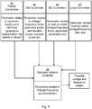
- the selection of the third frequency within the overlapping acceptable frequency range 71 from all the property limits from both microgrids by the microgrid network controller 32 is illustrated in figure 7 .
- the selection of the third voltage within an overlapping acceptable voltage range from all the property limits from both microgrids may be done correspondingly.
- Figure 8 is a schematic flow chart of an embodiment of the method of the present invention.
- the method is for synchronization of a first microgrid 1a, having a first voltage V1 and a first frequency f1, and a second microgrid 1b, having a second voltage V2 and a second frequency f2, with each other.
- the method comprises, for each of the first and second microgrids: determining Mia and Mib, respectively, a possible voltage range, and determining M2a and M2b, respectively, a possible frequency range.
- an overlapping voltage range comprised within both the possible voltage range of the first microgrid 1a and the possible voltage range of the second microgrid 1b is determined M3
- an overlapping frequency range comprised within both the possible frequency range of the first microgrid 1a and the possible frequency range of the second microgrid 1b is determined M4.
- a third voltage V3 is selected M5
- a third frequency f3 is selected M6.
- the first microgrid 1a is controlled M7 to change from the first voltage V1 and frequency f1 to the third voltage V3 and frequency f3
- the second microgrid 1b is controlled M8 to change from the second voltage V2 and frequency f2 to the third voltage V3 and frequency f3.
- the first and second microgrids are connected M9 to each other by closing the switch 2 between the first and second microgrids.
- the determining Mia and Mib, respectively, of a possible voltage range, and/or the determining M2a and M2b, respectively, of a possible frequency range is based on the loads 3 and power generators 4 available in said each microgrid 1a and 1b.
- the determining M3 of an overlapping voltage range and/or the determining M4 of an overlapping frequency range is based on any of:
Landscapes
- Engineering & Computer Science (AREA)
- Power Engineering (AREA)
- Physics & Mathematics (AREA)
- General Physics & Mathematics (AREA)
- Automation & Control Theory (AREA)
- Power Sources (AREA)
- Supply And Distribution Of Alternating Current (AREA)
- Force Measurement Appropriate To Specific Purposes (AREA)
- Stabilization Of Oscillater, Synchronisation, Frequency Synthesizers (AREA)
Description
- The present disclosure relates to a method for synchronization of a first microgrid and a second microgrid with each other.
- A microgrid is a localized grouping of electricity generation, energy storage, and loads that normally operates connected to a traditional centralized grid (macrogrid e.g. a power distribution grid) via a PCC. This single point of common coupling with the macrogrid can be disconnected, islanding the microgrid. Microgrids are part of a structure aiming at producing electrical power locally from many small energy sources, distributed generators (DGs). In a microgrid, a DG is connected via a converter which controls the output of the DG, i.e. the current injected into the microgrid.
- A microgrid (in grid connected mode, i.e. connected to the macrogrid) supplies the optimized or maximum power outputs from the connected DG sites and the rest of the power is supplied by the macrogrid, or excess power of the microgrid is injected into the macrogrid. The microgrid is connected to the macrogrid at a PCC through a controllable switch. This grid connection is lost during grid fault and the microgrid is islanded. Similarly, a microgrid may be connected to, or islanded from, another microgrid.
- In an AC microgrid, the frequency is the same everywhere in steady state while voltage may differ depending on the power flow. However, in a microgrid with a continuous change in DG output, load switching and low inertia, there is continuous frequency and voltage fluctuation on a small scale. The deviations are larger during large transients (i.e. DG fault etc.). In islanded mode, a microgrid may operate in a different frequency and voltage, compared to main grid frequency and voltage. During resynchronization, microgrid frequency is matched to the main grid frequency. Similar matching is also done for voltage magnitude between the microgrid and main grid. Before reconnection of the microgrid after islanding, resynchronization with voltage magnitude, phase angle and frequency matching is performed to ensure stability of the microgrid at reconnection. Once the voltage and frequency matching is achieved the breaker is closed at the instant of phase match. This is done to minimize the transient.
- A method performed in an electrical microgrid (4) for facilitating connection of a first AC power network (1) to a second AC power network (2) is disclosed in
WO 2016/023574 A1 which comprises, when the first power network is disconnected from the second power network, controlling the AC frequency (f1) of the first power network based on the AC frequency (f2) of the second power network for ensuring that when the first and second networks are connected power will flow from the power network of the first and second power networks having a higher frequency to the power network of the first and second power networks having a lower frequency. Furthermore, the method also comprises, after the controlling, connecting (3) the first power network to the second power network, whereby power, at the instant of connecting, flows from the power network of the first and second power networks having a higher frequency to the power network of the first and second power networks having a lower frequency. - Background art is also disclosed in documents
WO 2012/073228 A1 andDE 10 2010 001333 A1 . - It has now been realized that resynchronization of two islanded microgrids presents an opportunity to adjust system parameters (voltage and frequency) for each and both of the microgrids. This may e.g. be used in a nested microgrids scenario or for a collection of remote, typically small, microgrids grids in rural electrification.
- The resynchronization of two islanded microgrids operating at different voltage and frequency, as measured at (but on either side of) an open switch between the two microgrids, is in accordance with the present invention done at a third voltage and frequency which is selected based on properties and requirements of the two microgrids.
- Advantages may include enhanced stability, quicker attainment of steady state, better power flow management at tie line and improved power quality within each microgrid during the resynchronization process.
- According to an aspect of the present invention, there is provided a method for synchronization of a first microgrid, having a first voltage and a first frequency, and a second microgrid, having a second voltage and a second frequency, with each other. The method comprises for each of the first and second microgrids: determining a possible voltage range, and determining a possible frequency range, e.g. by calculating said possible voltage and frequency ranges or by receiving information about said possible voltage and frequency ranges. The method also comprises determining an overlapping voltage range comprised within both the possible voltage range of the first microgrid and the possible voltage range of the second microgrid. The method also comprises determining an overlapping frequency range comprised within both the possible frequency range of the first microgrid and the possible frequency range of the second microgrid. The method also comprises selecting a third voltage within the overlapping voltage range. The method also comprises selecting a third frequency within the overlapping frequency range. The method also comprises controlling the first microgrid to change from the first voltage and frequency to the third voltage and frequency. The method also comprises controlling the second microgrid to change from the second voltage and frequency to the third voltage and frequency. The method also comprises connecting the first and second microgrids to each other by closing a switch there between, e.g. by sending a control signal to said switch.
- According to another aspect of the present invention, there is provided a computer program product comprising computer-executable components for causing a microgrid network controller to perform an embodiment of the method of the present disclosure when the computer-executable components are run on processing circuitry comprised in the microgrid network controller.
- According to another aspect of the present invention, there is provided a microgrid network controller configured for synchronization of a first microgrid, having a first voltage and a first frequency, and a second microgrid, having a second voltage and a second frequency, with each other. The microgrid network controller comprises processing circuitry, and storage storing instructions executable by said processing circuitry whereby said microgrid network controller is operative to for each of the first and second microgrids: determine a possible voltage range, and determine a possible frequency range, e.g. by calculating said possible voltage and frequency ranges or by receiving information about said possible voltage and frequency ranges. The microgrid network controller is also operative to determine an overlapping voltage range comprised within both the possible voltage range of the first microgrid and the possible voltage range of the second microgrid. The microgrid network controller is also operative to determine an overlapping frequency range comprised within both the possible frequency range of the first microgrid and the possible frequency range of the second microgrid. The microgrid network controller is also operative to select a third voltage within the overlapping voltage range. The microgrid network controller is also operative to select a third frequency within the overlapping frequency range. The microgrid network controller is also operative to control the first microgrid to change from the first voltage and frequency to the third voltage and frequency. The microgrid network controller is also operative to control the second microgrid to change from the second voltage and frequency to the third voltage and frequency. The microgrid network controller is also operative to connect the first and second microgrids to each other by closing a switch there between, e.g. by sending a control signal to said switch.
- By determining the overlapping voltage and frequency ranges of the at least two microgrids and then changing the voltage and frequency of both microgrids to the selected third voltage and frequency, typically different from both the first and second voltages and frequencies, the synchronization voltage and frequency (i.e. the third voltage and frequency) may be more optimal for the operation of both microgrids, compared with changing the voltage and frequency of only one of the microgrids.
- As discussed above, the frequency of a microgrid is typically the same in the whole microgrid, while the voltage may vary in different parts of the microgrid. Thus, when the frequency and (especially) the voltage of a microgrid is discussed herein, the frequency and voltage at the Point of Common Coupling (PCC) with the other microgrid with which it is to be synchronized and connected is intended. The PCC is typically at a switch which is closed to connect the microgrids to each other.
- It is to be noted that any feature of any of the aspects may be applied to any other aspect, wherever appropriate. Likewise, any advantage of any of the aspects may apply to any of the other aspects. Other objectives, features and advantages of the enclosed embodiments will be apparent from the following detailed disclosure, from the attached dependent claims as well as from the drawings.
- Generally, all terms used in the claims are to be interpreted according to their ordinary meaning in the technical field, unless explicitly defined otherwise herein. All references to "a/an/the element, apparatus, component, means, step, etc." are to be interpreted openly as referring to at least one instance of the element, apparatus, component, means, step, etc., unless explicitly stated otherwise. The steps of any method disclosed herein do not have to be performed in the exact order disclosed, unless explicitly stated. The use of "first", "second" etc. for different features/components of the present disclosure are only intended to distinguish the features/components from other similar features/components and not to impart any order or hierarchy to the features/components.
- Embodiments will be described, by way of example, with reference to the accompanying drawings, in which:
-
Fig 1a is a schematic illustration of an embodiment of a microgrid system comprising a first and a second microgrid, in accordance with the present invention. -
Fig 1b is a more detailed schematic circuit diagram of an embodiment of a microgrid system comprising a first and a second microgrid, in accordance with the present invention. -
Fig 2 is a voltage and frequency diagram illustrating an embodiment of selection of a voltage and a frequency for resynchronization of two microgrids, in accordance with the present invention. -
Fig 3 is a schematic flow chart illustrating embodiments of the microgrid control structure, in accordance with the present invention. -
Fig 4 is a more detailed schematic flow chart illustrating example embodiments of the microgrid control structure, in accordance with the present invention. -
Fig 5 schematically illustrates embodiments of microgrid control activity for determining possible voltage and frequency ranges, in accordance with the present invention. -
Fig 6 schematically illustrates embodiments of microgrid control activity for selecting resynchronization voltage and frequency from the possible voltage and frequency ranges, in accordance with the present invention. -
Fig 7 schematically illustrates examples of the determining of possible voltage and frequency ranges and the selecting of resynchronization voltage and frequency, in accordance with the present invention. -
Fig 8 is a schematic flow chart of an embodiment of the method of the present invention. - Embodiments will now be described more fully hereinafter with reference to the accompanying drawings, in which certain embodiments are shown. However, other embodiments in many different forms are possible within the scope of the present disclosure. Rather, the following embodiments are provided by way of example so that this disclosure will be thorough and complete, and will fully convey the scope of the disclosure to those skilled in the art. Like numbers refer to like elements throughout the description.
-
Figures 1a and 1b illustrate two islanded microgrids, afirst microgrid 1a and asecond microgrid 1b, operating at different voltages and frequencies (V1, f1) and (V2, f2), respectively, e.g. as measured at either side of theopen switch 2 between the microgrids. Connection of the microgrids to each other by closing theswitch 2 is in accordance with the present invention done at a third voltage and frequency (V3, f3). Each of themicrogrids figure 1b . -
Figure 1b shows some examples of DGs 4 and loads 3 which may be included in any of the microgrids 1. DGs may e.g. include an energy storage (ES) 4a or 4d, e.g. a battery, supercapacitor or flywheel, arenewable energy source 4b such as a photovoltaic (PV) or wind power generator, and/or an Alternating Current (AC)power generator 4c. - As illustrated in
figure 2 , a new third voltage and frequency (V3, f3) is selected for (re)synchronization within the overlapping possible ranges. The possible frequency range of thefirst microgrid 1a is between fia and f1b, the possible frequency range of thesecond microgrid 1b is between f2a and f2b, the possible voltage range of thefirst microgrid 1a is between Via and Vib, and the possible voltage range of thesecond microgrid 1b is between V2a and V2b. The possible ranges are dependent on the assets (such as DGs 4 and loads 3) of the respective microgrid 1, and represents the voltages and frequencies which the microgrids may achieve depending on how they are operated. The two microgrids are then each controlled to achieve the new selected voltage and frequency (V3, f3). Once both the microgrids have achieved that, the switch, e.g. a circuit breaker (BRK), 2 is closed, typically at the instant of phase match. It is assumed that due to error in measurement and control, the frequency in the two microgrids may not be exactly identical to have phasor rotations. A small control error may be allowed to accelerate the synchronization process. - The first, second and third voltages Vi, V2 and V3 are typically all different from each other. Similarly, the first, second and third frequencies f1, f2, and f3 are typically all different from each other. However, in some cases, the first and second voltages V1 & V2 may be the same and/or the first and second frequencies f1 & f2 may be the same.
- The selection of the (re)synchronization (third) voltage V3 and frequency f3 within the overlapping possible ranges of the first and
second microgrids - 1. Requirements of critical loads 3 in the microgrids 1: This may relate to ensuring the power quality a critical load requires.
- 2. Common microgrid operating voltage/frequency when resynchronized: This may indicate a preference where the resynchronization voltage and frequency is selected based on anticipated voltage/frequency of the common system after resynchronization, e.g. after any load shedding etc. effected in response to islanding have been reversed.
- 3. Steady state power flow within the microgrids and power flow over the switch/PCC 2: This may ensure non-reversal of power flow during and after resynchronization, e.g. after any load shedding etc. effected in response to islanding have been reversed.
- 4. Stability: This may relate to microgrid stability and ensure the resynchronizing voltage V3 and/or frequency f3 to avoid system stability issues with the microgrid control.
- Thus, the third voltage and frequency may be selected within acceptable voltage and frequency ranges, within the possible ranges, with regard to properties of the first and second microgrids such as those listed above and in table 1 below.
Table 1: Microgrid properties for determining acceptable ranges. Property Description Determining acceptable range Critical Load The frequency bandwidth for the load is considered as the acceptable frequency changes at the load connection in the microgrid. The acceptable frequency is determined to be above the frequency for load shedding and within load requirement range. Common Frequency / voltage Based on the energy management of the microgrids when connected, the DGs and loads are considered to calculate the operating frequency, which may then be used as the third frequency. A load flow study of the common network of the connected microgrids. Steady-state power flow PCC power flow at steady state is considered so that power reversal does not happen. Third frequency close to steady state frequency so that the power flow when connecting is in the same direction as steady state power flow. Tie line (PCC) power flow limits are used to define the frequency of the common network of the connected microgrids. Stability Stability of the control loops dictates the possible frequency ranges microgrids can be operated in before being connected, as well as the system stability during connection. The frequency or voltage ranges are limited and calculated by the control ranges of the controllers employed for the voltage and frequency control. -
Figure 3 illustrates an embodiment of a control topology of thecontrol system 30 of the microgrids 1. The control system comprises themicrogrid network controller 32, which interfaces both the first and thesecond microgrid asset controllers 31a of assets (e.g. DGs 4 and loads 3) of thefirst microgrid 1a andassets controllers 31b of assets of thesecond microgrid 1b. The assets controllers 31 of each microgrid 1 provides the possible voltage and frequency ranges for each asset. Based on the microgrid properties described above, themicrogrid network controller 32 selects the resynchronization (third) voltage and frequency. The microgrid assets may then be controlled to achieve said third voltage and frequency for (re)synchronization. - The
microgrid network controller 32 comprises processingcircuitry 33 e.g. a central processing unit (CPU). Theprocessing circuitry 33 may comprise one or a plurality of processing units in the form of microprocessor(s). However, other suitable devices with computing capabilities could be comprised in theprocessing circuitry 33, e.g. an application specific integrated circuit (ASIC), a field programmable gate array (FPGA) or a complex programmable logic device (CPLD). Theprocessing circuitry 33 is configured to run one or several computer program(s) or software (SW) 35 stored in astorage 34 of one or several storage unit(s) e.g. a memory. The storage unit is regarded as a computer readable means as discussed herein and may e.g. be in the form of a Random Access Memory (RAM), a Flash memory or other solid state memory, or a hard disk, or be a combination thereof. Theprocessing circuitry 33 may also be configured to store data in thestorage 34, as needed. - Embodiments of the present invention may be conveniently implemented in the
microgrid network controller 32 using one or more conventional general purpose or specialized digital computer, computing device, machine, or microprocessor, including one or more processors, memory and/or computer readable storage media programmed according to the teachings of the present disclosure. Appropriate software coding can readily be prepared by skilled programmers based on the teachings of the present disclosure, as will be apparent to those skilled in the software art. - In some embodiments, the present invention includes a computer program product, e.g. the
storage 34 or an external device, which is a non-transitory storage medium or computer readable medium (media) having instructions stored thereon/in which can be used to program a computer to perform any of the methods/processes of the present invention. Examples of the storage medium can include, but is not limited to, any type of disk including floppy disks, optical discs, DVD, CD-ROMs, microdrive, and magneto-optical disks, ROMs, RAMs, EPROMs, EEPROMs, DRAMs, VRAMs, flash memory devices, magnetic or optical cards, nanosystems (including molecular memory ICs), or any type of media or device suitable for storing instructions and/or data. -
Figure 4 illustrates the example control topology of thecontrol system 30 in more detail. The asset controllers 31 of each of the first andsecond microgrid DG controllers 42a andload controllers 43a of thefirst microgrid 1a, andDG controllers 42b andload controllers 43b of thesecond microgrid 1b, as well asfeeder controllers - The
microgrid network controller 32 receives information about the possible changes in DGs 4 and loads 3 in eachmicrogrid microgrid network controller 32 considers any of the microgrid properties e.g. steady-state power flow, system stability, requirements of critical load(s), and/or common voltage and frequency, as discussed above, to determine the overlapping acceptable voltage and frequency ranges. The third voltage and frequency is then selected within said overlapping acceptable voltage and frequency ranges and used as operating voltage and frequency for synchronization of the microgrids. The microgrid network controller instructs the asset controllers 31 accordingly such that the microgrids are controlled and synchronized. - Some of the relevant parameter exchanged between the
controllers 32 and 41-44 (also including a special ES controller 44) in thecontrol system 30 is shown infigure 5 for calculating the possible voltage and frequency ranges. The participation of the controllers to scrutinize the control functions and determining the limits on voltage and frequency are shown infigure 6 . - The selection of the third frequency within the overlapping
acceptable frequency range 71 from all the property limits from both microgrids by themicrogrid network controller 32 is illustrated infigure 7 . The selection of the third voltage within an overlapping acceptable voltage range from all the property limits from both microgrids may be done correspondingly. -
Figure 8 is a schematic flow chart of an embodiment of the method of the present invention. The method is for synchronization of afirst microgrid 1a, having a first voltage V1 and a first frequency f1, and asecond microgrid 1b, having a second voltage V2 and a second frequency f2, with each other. The method comprises, for each of the first and second microgrids: determining Mia and Mib, respectively, a possible voltage range, and determining M2a and M2b, respectively, a possible frequency range. - Then, an overlapping voltage range comprised within both the possible voltage range of the
first microgrid 1a and the possible voltage range of thesecond microgrid 1b is determined M3, and an overlapping frequency range comprised within both the possible frequency range of thefirst microgrid 1a and the possible frequency range of thesecond microgrid 1b is determined M4. Within the overlapping voltage range, a third voltage V3 is selected M5, and within the overlapping frequency range, a third frequency f3 is selected M6. - Then, the
first microgrid 1a is controlled M7 to change from the first voltage V1 and frequency f1 to the third voltage V3 and frequency f3, and thesecond microgrid 1b is controlled M8 to change from the second voltage V2 and frequency f2 to the third voltage V3 and frequency f3. - When both the first and the second microgrids are operating substantially at the third voltage and frequency, the first and second microgrids are connected M9 to each other by closing the
switch 2 between the first and second microgrids. - In some embodiments of the present invention, the determining Mia and Mib, respectively, of a possible voltage range, and/or the determining M2a and M2b, respectively, of a possible frequency range is based on the loads 3 and power generators 4 available in said each
microgrid - In some embodiments of the present invention, the determining M3 of an overlapping voltage range and/or the determining M4 of an overlapping frequency range is based on any of:
- power requirements of critical loads 3 in the first and/or second microgrid;
- estimated operating voltage and/or frequency of the connected microgrids after the
switch 2 has been closed; - estimated steady-state power flow direction over the
switch 2 of the connected microgrids; and/or - stability of control loops within the
control system 30 of the microgrids. - The present disclosure has mainly been described above with reference to a few embodiments. However, as is readily appreciated by a person skilled in the art, other embodiments than the ones disclosed above are equally possible within the scope of the present disclosure, as defined by the appended claims.
Claims (12)
- A method for synchronization of a first microgrid (1a), having a first voltage (V1) and a first frequency (f1), and a second microgrid (1b), having a second voltage (V2) and a second frequency (f2), with each other, the method comprising:for each of the first and second microgrids:determining (M1a, M1b) a possible voltage range, anddetermining (M2a, M2b) a possible frequency range;determining (M3) an overlapping voltage range comprised within both the possible voltage range of the first microgrid (1a) and the possible voltage range of the second microgrid (1b);determining (M4) an overlapping frequency range (71) comprised within both the possible frequency range of the first microgrid (1a) and the possible frequency range of the second microgrid (1b);selecting (M5) a third voltage (V3) within the overlapping voltage range;selecting (M6) a third frequency (f3) within the overlapping frequency range;controlling (M7) the first microgrid (1a) to change from the first voltage (V1) and frequency (f1) to the third voltage (V3) and frequency (f3);controlling (M8) the second microgrid (1b) to change from the second voltage (V2) and frequency (f2) to the third voltage (V3) and frequency (f3); andconnecting (M9) the first and second microgrids to each other by closing a switch (2) there between.
- The method of claim 1, wherein the determining (M1a, M1b) of a possible voltage range, and/or the determining (M2a, M2b) of a possible frequency range is based on the loads (3) and power generators (4) available in said each microgrid (1a, 1b).
- The method of any preceding claim, wherein the determining (M3) of an overlapping voltage range is based on power requirements of critical loads (3) in the first and/or second microgrid.
- The method of any preceding claim, wherein the determining (M3) of an overlapping voltage range is based on estimated operating voltage of the connected microgrids after the switch (2) has been closed.
- The method of any preceding claim, wherein the determining (M3) of an overlapping voltage range is based on estimated steady-state power flow direction over the switch (2) of the connected microgrids.
- The method of any preceding claim, wherein the determining (M3) of an overlapping voltage range is based on stability of control loops within a control system (30) of the microgrids.
- The method of any preceding claim, wherein the determining (M4) of an overlapping frequency range is based on power requirements of critical loads (3) in the first and/or second microgrid.
- The method of any preceding claim, wherein the determining (M4) of an overlapping frequency range is based on estimated operating frequency of the connected microgrids after the switch (2) has been closed.
- The method of any preceding claim, wherein the determining (M4) of an overlapping frequency range is based on estimated steady-state power flow direction over the switch (2) of the connected microgrids.
- The method of any preceding claim, wherein the determining (M4) of an overlapping frequency range is based on stability of control loops within a control system (30) of the microgrids.
- A computer program product (34) comprising computer-executable components (35) for causing a microgrid network controller (32) to perform the method of any preceding claim when the computer-executable components are run on processing circuitry (33) comprised in the microgrid network controller.
- A microgrid network controller (32) for synchronization of a first microgrid (1a), having a first voltage (V1) and a first frequency (f1), and a second microgrid (1b), having a second voltage (V2) and a second frequency (f2), with each other, the microgrid network controller comprising:processing circuitry (33); andstorage (34) storing instructions (35) executable by said processing circuitry whereby said microgrid network controller is operative to:for each of the first and second microgrids:determine a possible voltage range, anddetermine a possible frequency range;determine an overlapping voltage range comprised within both the possible voltage range of the first microgrid (1a) and the possible voltage range of the second microgrid (1b);determine an overlapping frequency range comprised within both the possible frequency range of the first microgrid (1a) and the possible frequency range of the second microgrid (1b);select a third voltage (V3) within the overlapping voltage range;select a third frequency (f3) within the overlapping frequency range;control the first microgrid (1a) to change from the first voltage (V1) and frequency (f1) to the third voltage (V3) and frequency (f3);control the second microgrid (1b) to change from the second voltage (V2) and frequency (f2) to the third voltage (V3) and frequency (f3); andconnect the first and second microgrids to each other by closing a switch (2) there between.
Applications Claiming Priority (1)
| Application Number | Priority Date | Filing Date | Title |
|---|---|---|---|
| PCT/EP2016/078097 WO2018091102A1 (en) | 2016-11-18 | 2016-11-18 | Synchronization of microgrids with each other |
Publications (2)
| Publication Number | Publication Date |
|---|---|
| EP3542435A1 EP3542435A1 (en) | 2019-09-25 |
| EP3542435B1 true EP3542435B1 (en) | 2021-03-10 |
Family
ID=57348678
Family Applications (1)
| Application Number | Title | Priority Date | Filing Date |
|---|---|---|---|
| EP16798163.8A Active EP3542435B1 (en) | 2016-11-18 | 2016-11-18 | Synchronization of microgrids with each other |
Country Status (6)
| Country | Link |
|---|---|
| US (1) | US10879703B2 (en) |
| EP (1) | EP3542435B1 (en) |
| CN (1) | CN109923751B (en) |
| AU (1) | AU2016430166B2 (en) |
| SA (1) | SA519401800B1 (en) |
| WO (1) | WO2018091102A1 (en) |
Families Citing this family (3)
| Publication number | Priority date | Publication date | Assignee | Title |
|---|---|---|---|---|
| EP4063974B1 (en) * | 2021-03-23 | 2025-10-22 | ABB Schweiz AG | Controlling an industrial process using virtualized instances of control software |
| US11451065B1 (en) | 2021-12-21 | 2022-09-20 | King Fahd University Of Petroleum And Minerals | Voltage control and grid synchronization of microgrids in real time |
| US12413077B2 (en) * | 2023-10-31 | 2025-09-09 | Bloom Energy Corporation | Systems and methods for synchronization of inverters in a microgrid |
Family Cites Families (19)
| Publication number | Priority date | Publication date | Assignee | Title |
|---|---|---|---|---|
| US7521825B2 (en) | 2005-11-04 | 2009-04-21 | Wisconsin Alumni Research Foundation | Interface switch for distributed energy resources |
| DE102010001333A1 (en) * | 2010-01-28 | 2011-08-18 | Airbus Operations GmbH, 21129 | Method and device for providing an on-board AC voltage in an aircraft |
| US8310104B2 (en) * | 2010-03-14 | 2012-11-13 | Gengenbach Gary A | Substantially bumpless transfer grid synchronization |
| KR101038274B1 (en) * | 2010-04-09 | 2011-06-01 | 그리드온(주) | Micropower for Microgrid and its Control Method |
| EP2647098B1 (en) * | 2010-12-02 | 2017-08-09 | University of Limerick | Improvements in and relating to wind farms |
| WO2013015773A1 (en) | 2011-07-22 | 2013-01-31 | Petra Solar, Inc. | Supervisory control for scalable microgrid systems |
| TWI415359B (en) * | 2011-09-16 | 2013-11-11 | Nat Univ Tsing Hua | Drop control system for synchronous adjustment of commercial power parallel |
| US10439429B2 (en) | 2012-11-02 | 2019-10-08 | Lex Products, Llc | Modular microgrid unit and method of use |
| US9620994B2 (en) * | 2013-01-17 | 2017-04-11 | Eaton Corporation | Method and system of anti-islanding of a microgrid in a grid-connected microgrid system |
| US9454137B2 (en) * | 2013-03-01 | 2016-09-27 | Honeywell International Inc. | System and method of large area microgrid stability controls |
| CN104836334B (en) * | 2014-02-08 | 2017-08-25 | 中国农业大学 | A kind of autonomous and coordinated control system of low pressure micro-capacitance sensor group |
| US9720395B2 (en) * | 2014-03-04 | 2017-08-01 | Nec Corporation | Synchronization control for reconnecting microgrid to main grid after islanding |
| CN104917199B (en) | 2014-03-14 | 2019-11-19 | 长沙理工大学 | Grid-connected flexible series-parallel multifunctional energy controller for AC/DC microgrid |
| US20150295581A1 (en) * | 2014-04-10 | 2015-10-15 | Nec Laboratories America, Inc. | Distributed Cooperative Control for Microgrid Resynchronization and Reconnection |
| CN106797122A (en) * | 2014-08-11 | 2017-05-31 | Abb瑞士股份有限公司 | Microgrid Control |
| CN107112761B (en) * | 2014-11-04 | 2019-07-26 | Abb瑞士股份有限公司 | Control method and system for microgrid |
| US9812863B2 (en) * | 2014-12-18 | 2017-11-07 | Solantro Semiconductor Corp. | Distributed electrical microgrid control |
| US10050445B2 (en) * | 2015-07-13 | 2018-08-14 | Sparq Systems Inc. | PV inverter with micro/nano-grid integration capability |
| US10044192B2 (en) * | 2016-02-05 | 2018-08-07 | Abb Schweiz Ag | Participation factor based method for resynchronization of microgrids |
-
2016
- 2016-11-18 US US16/461,893 patent/US10879703B2/en active Active
- 2016-11-18 WO PCT/EP2016/078097 patent/WO2018091102A1/en not_active Ceased
- 2016-11-18 CN CN201680090701.6A patent/CN109923751B/en active Active
- 2016-11-18 EP EP16798163.8A patent/EP3542435B1/en active Active
- 2016-11-18 AU AU2016430166A patent/AU2016430166B2/en active Active
-
2019
- 2019-05-16 SA SA519401800A patent/SA519401800B1/en unknown
Non-Patent Citations (1)
| Title |
|---|
| None * |
Also Published As
| Publication number | Publication date |
|---|---|
| SA519401800B1 (en) | 2022-07-07 |
| EP3542435A1 (en) | 2019-09-25 |
| CN109923751A (en) | 2019-06-21 |
| AU2016430166A1 (en) | 2019-06-06 |
| CN109923751B (en) | 2020-01-10 |
| WO2018091102A1 (en) | 2018-05-24 |
| US10879703B2 (en) | 2020-12-29 |
| US20190334351A1 (en) | 2019-10-31 |
| AU2016430166B2 (en) | 2021-03-11 |
Similar Documents
| Publication | Publication Date | Title |
|---|---|---|
| Rajesh et al. | A review on control of ac microgrid | |
| Li et al. | Artificial neural networks for Volt/VAR control of DER inverters at the grid edge | |
| Simpson-Porco et al. | Secondary frequency and voltage control of islanded microgrids via distributed averaging | |
| EP3114745B1 (en) | Control of a microgrid | |
| Lidula et al. | Voltage balancing and synchronization of microgrids with highly unbalanced loads | |
| US20140316604A1 (en) | Method for active control of frequency and voltage in a power supply grid with decentralized power supply systems | |
| US11283263B2 (en) | Microgrid segmentation | |
| AU2014410506B2 (en) | Control of a microgrid | |
| EP3542435B1 (en) | Synchronization of microgrids with each other | |
| Li et al. | A converter-based battery energy storage system emulator for the controller testing of a microgrid with dynamic boundaries and multiple source locations | |
| WO2017097354A1 (en) | Control of a microgrid | |
| Roslan et al. | Centralize control power sharing scheme of parallel connected inverters for microgrids | |
| Nshuti | Centralized and decentralized control of microgrids | |
| Lee et al. | Smart storage system for seamless transition of customers with intermittent renewable energy sources into microgrid | |
| ul Hassan et al. | Advanced control techniques for micro-grids power quality improvement | |
| Hashmi et al. | An improved control scheme for power sharing between distributed power converters in islanded AC microgrids | |
| Eberlein et al. | Influence of inaccurate low voltage microgrid synchronization on synchronous generators | |
| Xiao et al. | A virtual inertia control strategy of interlinking converters in islanded hybrid AC/DC microgrid | |
| Małaczek et al. | Control of low voltage microgrid in autonomous operation mode | |
| Yao et al. | Single phase DQ frame Glover McFarlane H infinity robust droop controller design | |
| Mohamed | Stability Enhancement of the Microgrid Under High-depth of Penetration of Electronically-Coupled Resources | |
| Zhong et al. | Novel active synchronization strategy for multi-bus microgrid with distributed cooperation control |
Legal Events
| Date | Code | Title | Description |
|---|---|---|---|
| STAA | Information on the status of an ep patent application or granted ep patent |
Free format text: STATUS: UNKNOWN |
|
| STAA | Information on the status of an ep patent application or granted ep patent |
Free format text: STATUS: THE INTERNATIONAL PUBLICATION HAS BEEN MADE |
|
| PUAI | Public reference made under article 153(3) epc to a published international application that has entered the european phase |
Free format text: ORIGINAL CODE: 0009012 |
|
| STAA | Information on the status of an ep patent application or granted ep patent |
Free format text: STATUS: REQUEST FOR EXAMINATION WAS MADE |
|
| 17P | Request for examination filed |
Effective date: 20190618 |
|
| AK | Designated contracting states |
Kind code of ref document: A1 Designated state(s): AL AT BE BG CH CY CZ DE DK EE ES FI FR GB GR HR HU IE IS IT LI LT LU LV MC MK MT NL NO PL PT RO RS SE SI SK SM TR |
|
| AX | Request for extension of the european patent |
Extension state: BA ME |
|
| DAV | Request for validation of the european patent (deleted) | ||
| DAX | Request for extension of the european patent (deleted) | ||
| GRAP | Despatch of communication of intention to grant a patent |
Free format text: ORIGINAL CODE: EPIDOSNIGR1 |
|
| STAA | Information on the status of an ep patent application or granted ep patent |
Free format text: STATUS: GRANT OF PATENT IS INTENDED |
|
| INTG | Intention to grant announced |
Effective date: 20200514 |
|
| RAP1 | Party data changed (applicant data changed or rights of an application transferred) |
Owner name: ABB POWER GRIDS SWITZERLAND AG |
|
| GRAJ | Information related to disapproval of communication of intention to grant by the applicant or resumption of examination proceedings by the epo deleted |
Free format text: ORIGINAL CODE: EPIDOSDIGR1 |
|
| STAA | Information on the status of an ep patent application or granted ep patent |
Free format text: STATUS: REQUEST FOR EXAMINATION WAS MADE |
|
| GRAP | Despatch of communication of intention to grant a patent |
Free format text: ORIGINAL CODE: EPIDOSNIGR1 |
|
| STAA | Information on the status of an ep patent application or granted ep patent |
Free format text: STATUS: GRANT OF PATENT IS INTENDED |
|
| INTC | Intention to grant announced (deleted) | ||
| INTG | Intention to grant announced |
Effective date: 20201009 |
|
| GRAS | Grant fee paid |
Free format text: ORIGINAL CODE: EPIDOSNIGR3 |
|
| GRAA | (expected) grant |
Free format text: ORIGINAL CODE: 0009210 |
|
| STAA | Information on the status of an ep patent application or granted ep patent |
Free format text: STATUS: THE PATENT HAS BEEN GRANTED |
|
| AK | Designated contracting states |
Kind code of ref document: B1 Designated state(s): AL AT BE BG CH CY CZ DE DK EE ES FI FR GB GR HR HU IE IS IT LI LT LU LV MC MK MT NL NO PL PT RO RS SE SI SK SM TR |
|
| REG | Reference to a national code |
Ref country code: GB Ref legal event code: FG4D |
|
| REG | Reference to a national code |
Ref country code: AT Ref legal event code: REF Ref document number: 1370884 Country of ref document: AT Kind code of ref document: T Effective date: 20210315 Ref country code: CH Ref legal event code: EP |
|
| REG | Reference to a national code |
Ref country code: IE Ref legal event code: FG4D |
|
| REG | Reference to a national code |
Ref country code: DE Ref legal event code: R096 Ref document number: 602016054093 Country of ref document: DE |
|
| REG | Reference to a national code |
Ref country code: LT Ref legal event code: MG9D |
|
| PG25 | Lapsed in a contracting state [announced via postgrant information from national office to epo] |
Ref country code: HR Free format text: LAPSE BECAUSE OF FAILURE TO SUBMIT A TRANSLATION OF THE DESCRIPTION OR TO PAY THE FEE WITHIN THE PRESCRIBED TIME-LIMIT Effective date: 20210310 Ref country code: FI Free format text: LAPSE BECAUSE OF FAILURE TO SUBMIT A TRANSLATION OF THE DESCRIPTION OR TO PAY THE FEE WITHIN THE PRESCRIBED TIME-LIMIT Effective date: 20210310 Ref country code: GR Free format text: LAPSE BECAUSE OF FAILURE TO SUBMIT A TRANSLATION OF THE DESCRIPTION OR TO PAY THE FEE WITHIN THE PRESCRIBED TIME-LIMIT Effective date: 20210611 Ref country code: NO Free format text: LAPSE BECAUSE OF FAILURE TO SUBMIT A TRANSLATION OF THE DESCRIPTION OR TO PAY THE FEE WITHIN THE PRESCRIBED TIME-LIMIT Effective date: 20210610 Ref country code: BG Free format text: LAPSE BECAUSE OF FAILURE TO SUBMIT A TRANSLATION OF THE DESCRIPTION OR TO PAY THE FEE WITHIN THE PRESCRIBED TIME-LIMIT Effective date: 20210610 Ref country code: LT Free format text: LAPSE BECAUSE OF FAILURE TO SUBMIT A TRANSLATION OF THE DESCRIPTION OR TO PAY THE FEE WITHIN THE PRESCRIBED TIME-LIMIT Effective date: 20210310 |
|
| REG | Reference to a national code |
Ref country code: AT Ref legal event code: MK05 Ref document number: 1370884 Country of ref document: AT Kind code of ref document: T Effective date: 20210310 |
|
| REG | Reference to a national code |
Ref country code: NL Ref legal event code: MP Effective date: 20210310 |
|
| PG25 | Lapsed in a contracting state [announced via postgrant information from national office to epo] |
Ref country code: RS Free format text: LAPSE BECAUSE OF FAILURE TO SUBMIT A TRANSLATION OF THE DESCRIPTION OR TO PAY THE FEE WITHIN THE PRESCRIBED TIME-LIMIT Effective date: 20210310 Ref country code: LV Free format text: LAPSE BECAUSE OF FAILURE TO SUBMIT A TRANSLATION OF THE DESCRIPTION OR TO PAY THE FEE WITHIN THE PRESCRIBED TIME-LIMIT Effective date: 20210310 Ref country code: SE Free format text: LAPSE BECAUSE OF FAILURE TO SUBMIT A TRANSLATION OF THE DESCRIPTION OR TO PAY THE FEE WITHIN THE PRESCRIBED TIME-LIMIT Effective date: 20210310 |
|
| PG25 | Lapsed in a contracting state [announced via postgrant information from national office to epo] |
Ref country code: NL Free format text: LAPSE BECAUSE OF FAILURE TO SUBMIT A TRANSLATION OF THE DESCRIPTION OR TO PAY THE FEE WITHIN THE PRESCRIBED TIME-LIMIT Effective date: 20210310 |
|
| PG25 | Lapsed in a contracting state [announced via postgrant information from national office to epo] |
Ref country code: CZ Free format text: LAPSE BECAUSE OF FAILURE TO SUBMIT A TRANSLATION OF THE DESCRIPTION OR TO PAY THE FEE WITHIN THE PRESCRIBED TIME-LIMIT Effective date: 20210310 Ref country code: EE Free format text: LAPSE BECAUSE OF FAILURE TO SUBMIT A TRANSLATION OF THE DESCRIPTION OR TO PAY THE FEE WITHIN THE PRESCRIBED TIME-LIMIT Effective date: 20210310 Ref country code: SM Free format text: LAPSE BECAUSE OF FAILURE TO SUBMIT A TRANSLATION OF THE DESCRIPTION OR TO PAY THE FEE WITHIN THE PRESCRIBED TIME-LIMIT Effective date: 20210310 Ref country code: AT Free format text: LAPSE BECAUSE OF FAILURE TO SUBMIT A TRANSLATION OF THE DESCRIPTION OR TO PAY THE FEE WITHIN THE PRESCRIBED TIME-LIMIT Effective date: 20210310 |
|
| PG25 | Lapsed in a contracting state [announced via postgrant information from national office to epo] |
Ref country code: IS Free format text: LAPSE BECAUSE OF FAILURE TO SUBMIT A TRANSLATION OF THE DESCRIPTION OR TO PAY THE FEE WITHIN THE PRESCRIBED TIME-LIMIT Effective date: 20210710 Ref country code: PL Free format text: LAPSE BECAUSE OF FAILURE TO SUBMIT A TRANSLATION OF THE DESCRIPTION OR TO PAY THE FEE WITHIN THE PRESCRIBED TIME-LIMIT Effective date: 20210310 Ref country code: PT Free format text: LAPSE BECAUSE OF FAILURE TO SUBMIT A TRANSLATION OF THE DESCRIPTION OR TO PAY THE FEE WITHIN THE PRESCRIBED TIME-LIMIT Effective date: 20210712 Ref country code: RO Free format text: LAPSE BECAUSE OF FAILURE TO SUBMIT A TRANSLATION OF THE DESCRIPTION OR TO PAY THE FEE WITHIN THE PRESCRIBED TIME-LIMIT Effective date: 20210310 Ref country code: SK Free format text: LAPSE BECAUSE OF FAILURE TO SUBMIT A TRANSLATION OF THE DESCRIPTION OR TO PAY THE FEE WITHIN THE PRESCRIBED TIME-LIMIT Effective date: 20210310 |
|
| REG | Reference to a national code |
Ref country code: DE Ref legal event code: R097 Ref document number: 602016054093 Country of ref document: DE |
|
| PLBE | No opposition filed within time limit |
Free format text: ORIGINAL CODE: 0009261 |
|
| STAA | Information on the status of an ep patent application or granted ep patent |
Free format text: STATUS: NO OPPOSITION FILED WITHIN TIME LIMIT |
|
| RAP2 | Party data changed (patent owner data changed or rights of a patent transferred) |
Owner name: ABB SCHWEIZ AG Owner name: HITACHI ENERGY SWITZERLAND AG |
|
| PG25 | Lapsed in a contracting state [announced via postgrant information from national office to epo] |
Ref country code: DK Free format text: LAPSE BECAUSE OF FAILURE TO SUBMIT A TRANSLATION OF THE DESCRIPTION OR TO PAY THE FEE WITHIN THE PRESCRIBED TIME-LIMIT Effective date: 20210310 Ref country code: AL Free format text: LAPSE BECAUSE OF FAILURE TO SUBMIT A TRANSLATION OF THE DESCRIPTION OR TO PAY THE FEE WITHIN THE PRESCRIBED TIME-LIMIT Effective date: 20210310 Ref country code: ES Free format text: LAPSE BECAUSE OF FAILURE TO SUBMIT A TRANSLATION OF THE DESCRIPTION OR TO PAY THE FEE WITHIN THE PRESCRIBED TIME-LIMIT Effective date: 20210310 |
|
| 26N | No opposition filed |
Effective date: 20211213 |
|
| PG25 | Lapsed in a contracting state [announced via postgrant information from national office to epo] |
Ref country code: SI Free format text: LAPSE BECAUSE OF FAILURE TO SUBMIT A TRANSLATION OF THE DESCRIPTION OR TO PAY THE FEE WITHIN THE PRESCRIBED TIME-LIMIT Effective date: 20210310 |
|
| REG | Reference to a national code |
Ref country code: DE Ref legal event code: R081 Ref document number: 602016054093 Country of ref document: DE Owner name: HITACHI ENERGY SWITZERLAND AG, CH Free format text: FORMER OWNER: ABB POWER GRIDS SWITZERLAND AG, BADEN, CH Ref country code: DE Ref legal event code: R081 Ref document number: 602016054093 Country of ref document: DE Owner name: ABB SCHWEIZ AG, CH Free format text: FORMER OWNER: ABB POWER GRIDS SWITZERLAND AG, BADEN, CH Ref country code: DE Ref legal event code: R081 Ref document number: 602016054093 Country of ref document: DE Owner name: HITACHI ENERGY LTD, CH Free format text: FORMER OWNER: ABB POWER GRIDS SWITZERLAND AG, BADEN, CH |
|
| PG25 | Lapsed in a contracting state [announced via postgrant information from national office to epo] |
Ref country code: IS Free format text: LAPSE BECAUSE OF FAILURE TO SUBMIT A TRANSLATION OF THE DESCRIPTION OR TO PAY THE FEE WITHIN THE PRESCRIBED TIME-LIMIT Effective date: 20210710 |
|
| REG | Reference to a national code |
Ref country code: GB Ref legal event code: 732E Free format text: REGISTERED BETWEEN 20220519 AND 20220525 |
|
| PG25 | Lapsed in a contracting state [announced via postgrant information from national office to epo] |
Ref country code: MC Free format text: LAPSE BECAUSE OF FAILURE TO SUBMIT A TRANSLATION OF THE DESCRIPTION OR TO PAY THE FEE WITHIN THE PRESCRIBED TIME-LIMIT Effective date: 20210310 |
|
| REG | Reference to a national code |
Ref country code: CH Ref legal event code: PL |
|
| PG25 | Lapsed in a contracting state [announced via postgrant information from national office to epo] |
Ref country code: LU Free format text: LAPSE BECAUSE OF NON-PAYMENT OF DUE FEES Effective date: 20211118 Ref country code: BE Free format text: LAPSE BECAUSE OF NON-PAYMENT OF DUE FEES Effective date: 20211130 |
|
| REG | Reference to a national code |
Ref country code: BE Ref legal event code: MM Effective date: 20211130 |
|
| PG25 | Lapsed in a contracting state [announced via postgrant information from national office to epo] |
Ref country code: IE Free format text: LAPSE BECAUSE OF NON-PAYMENT OF DUE FEES Effective date: 20211118 |
|
| PG25 | Lapsed in a contracting state [announced via postgrant information from national office to epo] |
Ref country code: CY Free format text: LAPSE BECAUSE OF FAILURE TO SUBMIT A TRANSLATION OF THE DESCRIPTION OR TO PAY THE FEE WITHIN THE PRESCRIBED TIME-LIMIT Effective date: 20210310 |
|
| PG25 | Lapsed in a contracting state [announced via postgrant information from national office to epo] |
Ref country code: LI Free format text: LAPSE BECAUSE OF NON-PAYMENT OF DUE FEES Effective date: 20220630 Ref country code: HU Free format text: LAPSE BECAUSE OF FAILURE TO SUBMIT A TRANSLATION OF THE DESCRIPTION OR TO PAY THE FEE WITHIN THE PRESCRIBED TIME-LIMIT; INVALID AB INITIO Effective date: 20161118 Ref country code: CH Free format text: LAPSE BECAUSE OF NON-PAYMENT OF DUE FEES Effective date: 20220630 |
|
| PG25 | Lapsed in a contracting state [announced via postgrant information from national office to epo] |
Ref country code: MK Free format text: LAPSE BECAUSE OF FAILURE TO SUBMIT A TRANSLATION OF THE DESCRIPTION OR TO PAY THE FEE WITHIN THE PRESCRIBED TIME-LIMIT Effective date: 20210310 |
|
| REG | Reference to a national code |
Ref country code: GB Ref legal event code: 732E Free format text: REGISTERED BETWEEN 20240530 AND 20240605 |
|
| PG25 | Lapsed in a contracting state [announced via postgrant information from national office to epo] |
Ref country code: TR Free format text: LAPSE BECAUSE OF FAILURE TO SUBMIT A TRANSLATION OF THE DESCRIPTION OR TO PAY THE FEE WITHIN THE PRESCRIBED TIME-LIMIT Effective date: 20210310 |
|
| REG | Reference to a national code |
Ref country code: DE Ref legal event code: R082 Ref document number: 602016054093 Country of ref document: DE Representative=s name: DENNEMEYER & ASSOCIATES S.A., DE Ref country code: DE Ref legal event code: R081 Ref document number: 602016054093 Country of ref document: DE Owner name: HITACHI ENERGY LTD, CH Free format text: FORMER OWNERS: ABB SCHWEIZ AG, BADEN, CH; HITACHI ENERGY SWITZERLAND AG, BADEN, CH Ref country code: DE Ref legal event code: R081 Ref document number: 602016054093 Country of ref document: DE Owner name: ABB SCHWEIZ AG, CH Free format text: FORMER OWNERS: ABB SCHWEIZ AG, BADEN, CH; HITACHI ENERGY SWITZERLAND AG, BADEN, CH |
|
| PG25 | Lapsed in a contracting state [announced via postgrant information from national office to epo] |
Ref country code: MT Free format text: LAPSE BECAUSE OF FAILURE TO SUBMIT A TRANSLATION OF THE DESCRIPTION OR TO PAY THE FEE WITHIN THE PRESCRIBED TIME-LIMIT Effective date: 20210310 |
|
| PGFP | Annual fee paid to national office [announced via postgrant information from national office to epo] |
Ref country code: DE Payment date: 20251119 Year of fee payment: 10 |
|
| PGFP | Annual fee paid to national office [announced via postgrant information from national office to epo] |
Ref country code: GB Payment date: 20251121 Year of fee payment: 10 |
|
| PGFP | Annual fee paid to national office [announced via postgrant information from national office to epo] |
Ref country code: IT Payment date: 20251125 Year of fee payment: 10 |
|
| PGFP | Annual fee paid to national office [announced via postgrant information from national office to epo] |
Ref country code: FR Payment date: 20251126 Year of fee payment: 10 |