EP3542433B1 - Monitoring arrangement for domestic or commercial electrical appliances - Google Patents
Monitoring arrangement for domestic or commercial electrical appliances Download PDFInfo
- Publication number
- EP3542433B1 EP3542433B1 EP16801403.3A EP16801403A EP3542433B1 EP 3542433 B1 EP3542433 B1 EP 3542433B1 EP 16801403 A EP16801403 A EP 16801403A EP 3542433 B1 EP3542433 B1 EP 3542433B1
- Authority
- EP
- European Patent Office
- Prior art keywords
- electric
- current
- electric appliance
- domestic
- power
- Prior art date
- Legal status (The legal status is an assumption and is not a legal conclusion. Google has not performed a legal analysis and makes no representation as to the accuracy of the status listed.)
- Active
Links
Images


Classifications
-
- H—ELECTRICITY
- H02—GENERATION; CONVERSION OR DISTRIBUTION OF ELECTRIC POWER
- H02J—ELECTRIC POWER NETWORKS; CIRCUIT ARRANGEMENTS OR SYSTEMS FOR SUPPLYING OR DISTRIBUTING ELECTRIC POWER; SYSTEMS FOR STORING ELECTRIC ENERGY
- H02J3/00—Circuit arrangements for AC mains or AC distribution networks
- H02J3/01—Arrangements for reducing harmonics or ripples
-
- G—PHYSICS
- G01—MEASURING; TESTING
- G01R—MEASURING ELECTRIC VARIABLES; MEASURING MAGNETIC VARIABLES
- G01R19/00—Arrangements for measuring currents or voltages or for indicating presence or sign thereof
- G01R19/25—Arrangements for measuring currents or voltages or for indicating presence or sign thereof using digital measurement techniques
- G01R19/2513—Arrangements for monitoring electric power systems, e.g. power lines or loads; Logging
-
- G—PHYSICS
- G05—CONTROLLING; REGULATING
- G05D—SYSTEMS FOR CONTROLLING OR REGULATING NON-ELECTRIC VARIABLES
- G05D23/00—Control of temperature
- G05D23/19—Control of temperature characterised by the use of electric means
- G05D23/1917—Control of temperature characterised by the use of electric means using digital means
-
- Y—GENERAL TAGGING OF NEW TECHNOLOGICAL DEVELOPMENTS; GENERAL TAGGING OF CROSS-SECTIONAL TECHNOLOGIES SPANNING OVER SEVERAL SECTIONS OF THE IPC; TECHNICAL SUBJECTS COVERED BY FORMER USPC CROSS-REFERENCE ART COLLECTIONS [XRACs] AND DIGESTS
- Y02—TECHNOLOGIES OR APPLICATIONS FOR MITIGATION OR ADAPTATION AGAINST CLIMATE CHANGE
- Y02E—REDUCTION OF GREENHOUSE GAS [GHG] EMISSIONS, RELATED TO ENERGY GENERATION, TRANSMISSION OR DISTRIBUTION
- Y02E10/00—Energy generation through renewable energy sources
- Y02E10/50—Photovoltaic [PV] energy
- Y02E10/56—Power conversion systems, e.g. maximum power point trackers
-
- Y—GENERAL TAGGING OF NEW TECHNOLOGICAL DEVELOPMENTS; GENERAL TAGGING OF CROSS-SECTIONAL TECHNOLOGIES SPANNING OVER SEVERAL SECTIONS OF THE IPC; TECHNICAL SUBJECTS COVERED BY FORMER USPC CROSS-REFERENCE ART COLLECTIONS [XRACs] AND DIGESTS
- Y02—TECHNOLOGIES OR APPLICATIONS FOR MITIGATION OR ADAPTATION AGAINST CLIMATE CHANGE
- Y02E—REDUCTION OF GREENHOUSE GAS [GHG] EMISSIONS, RELATED TO ENERGY GENERATION, TRANSMISSION OR DISTRIBUTION
- Y02E40/00—Technologies for an efficient electrical power generation, transmission or distribution
- Y02E40/40—Arrangements for reducing harmonics
Definitions
- the present invention refers in general to the field of domestic or commercial (called also professional) electric appliances, and more particularly to a monitoring arrangement for domestic or commercial electric appliances like a domestic o commercial refrigerator, a domestic or commercial laundry washing machine, a domestic or commercial laundry dryer machine, a domestic or commercial combined laundry washing and drying machine, a domestic or commercial dishwasher, a domestic or commercial oven, an air conditioner, and the like, and in general for all those domestic or commercial electric appliances comprising at least one electric load adapted for being supplied with AC current.
- patent US 4741170 discloses an improved control for a refrigerator.
- Critical components such as fresh food and freezer compartment temperature sensors, temperature set devices and baffle are sampled to confirm that each is operational.
- the control Upon diagnosis of a critical component failure or of multiple component failures, the control, using stored control parameters, operates the remaining components in a manner that will continue to preserve food.
- Patent US 46151779 discloses an apparatus and method for detecting a failure in an automatic defrost system for a refrigerator.
- a current sensor means monitors the current supplied to the defrost heater and generates an "on" signal when current is sensed in the defrost heater circuit.
- a microprocessor determines the "off" time, that is the time between successive "on” signals, and compares this time to a predetermined reference time longer than the normal "off” time.
- a user discernible signal is generated upon detection of an "off" time greater than the reference time, signifying to the user that the defrost system is not operating properly, and corrective action may be necessary.
- Patent JPH04359778 discloses a current transformer for detecting a current flowing a power source line.
- a controller compares the detected current value of the transformer with both upper and lower reference values, judges as a malfunction if the current value is out of both the upper and lower reference values, displays it on a display unit, and opens a relay switch of the component which is conducted at that time.
- the controller varies the upper reference values and the lower reference values in response to the component to be conducted of a dew-preventive heater, a defrosting heater, a driving motor of a fan and a compressor.
- US 2016/080840 discloses to capture at a relatively high data rate power consumption related data for the power source supplying an entire household or other group of appliances.
- the raw data is analysed to remove redundancy and to identify pertinent features, and then the more informative of these features are selected.
- the analysis and selection of features are pre-processing tasks that are performed on-site, on the same piece of hardware that acquires the raw data and transmits the pre-processed data to the server. By transmitting selective data to a remote server, only a low bandwidth is required for the transmission.
- An aspect of the present invention related to a domestic or commercial (typically called also professional) electric appliance.
- the domestic or commercial electric appliance comprises at least one electric load, an AC power supply input connectable to an AC power source for receiving electric power from said power source and arranged to supply electric power to said at least one electric load.
- the AC power source comprises a private available AC power supply connected to said power supply unit, wherein the private available AC power supply is an AC power generator which is directly managed by a private user, comprises a modulator unit adapted to modulate AC current generated by the private AC power supply with an identification signal when the AC power generator is operating and delivering additional power and further comprises a domestic photovoltaic panel or a micro-wind turbine generator.
- the private available AC power supply is an AC power generator which is directly managed by a private user, comprises a modulator unit adapted to modulate AC current generated by the private AC power supply with an identification signal when the AC power generator is operating and delivering additional power and further comprises a domestic photovoltaic panel or a micro-wind turbine generator.
- the domestic or commercial electric appliance further comprises a current sensor for sensing an AC current absorbed by the electric appliance from the AC power source (i.e. the overall current consumption of the electric appliance), and a processing unit for carrying out an harmonic analysis on a sensed AC current sensed by the current sensor and for driving the at least one electric load based on an outcome of said harmonic analysis.
- a current sensor for sensing an AC current absorbed by the electric appliance from the AC power source (i.e. the overall current consumption of the electric appliance)
- a processing unit for carrying out an harmonic analysis on a sensed AC current sensed by the current sensor and for driving the at least one electric load based on an outcome of said harmonic analysis.
- the processing unit is configured to assess a presence, in a sensed AC current, of at least one secondary component oscillating at a frequency higher than a fundamental frequency of a main component of said sensed AC current, and to detect if said at least one secondary component corresponds to an identification signal generated by the private available AC power supply, wherein the processing unit is further configured to drive said at least one electric load based on said identification signal.
- said current sensor is a Hall current sensor.
- the processing unit is configured to calculate the total harmonic distortion of the sensed AC current, and to assess at least one among:
- the processing unit is configured to carry out the harmonic analysis on the sensed AC current by applying a Fast Fourier Transform to the sensed AC current.
- the processing unit is configured to assess anomalous operation conditions or malfunction conditions of the at least one electric load based on the sensed AC current.
- the processing unit is further configured to assess the electric power consumption of the at least one electric load based on the sensed AC current.
- the processing unit is further configured to assess an overload condition of the AC power source based on sensed AC current.
- said electric appliance is a refrigerator
- said at least one electric load comprise at least one among an inverter unit, a compressor unit, and a defrost heating resistor.
- said electric appliance is a laundry washing machine
- said at least one electric load comprises at least one among a drain pump, a recirculation pump, a drum motor circuit, a heating resistor.
- said electric appliance is a laundry dryer machine
- said at least one electric load comprises at least one among a drum motor circuit, a heating resistor, a compressor unit, a fan.
- said electric appliance is an oven
- said at least one electric load comprises at least one among a heating resistor, a microwave generator unit, a fan.
- Another aspect of the present invention relates to an electric system comprising a domestic or commercial (typically called also professional) electric appliance and an AC power source connected to the AC power supply input of said domestic or commercial electric appliance.
- Said AC power source is adapted to provide to said AC power supply input an electric power having a fundamental frequency being an utility frequency of a public available AC power supply.
- said AC power source includes at least one private available AC power supply, wherein the private available AC power supply is an AC power generator which is directly managed by a private user.
- Each private available AC power supply is configured to generate additional electric power and a corresponding identification signal when activated.
- Embodiments of the present invention relate to a domestic or commercial (called also professional) electric appliance designed to be supplied with AC current and provided with the capability of monitoring the AC current absorbed by the electric appliance itself (i.e. the overall current consumption of the electric appliance) for obtaining real-time information about its operating condition as well as about the surrounding environment.
- a domestic or commercial (called also professional) electric appliance designed to be supplied with AC current and provided with the capability of monitoring the AC current absorbed by the electric appliance itself (i.e. the overall current consumption of the electric appliance) for obtaining real-time information about its operating condition as well as about the surrounding environment.
- an electric appliance 100 e.g., an electric household appliance - such as a refrigerator, a laundry washing machine, a laundry dryer machine, a combined laundry washing and drying machine, a dishwasher, an oven, an air conditioner and the like - located in a building 105, is connected to a power socket 110 for being supplied with AC power.
- an electric appliance 100 e.g., an electric household appliance - such as a refrigerator, a laundry washing machine, a laundry dryer machine, a combined laundry washing and drying machine, a dishwasher, an oven, an air conditioner and the like - located in a building 105.
- the electric appliance 100 is an household appliance for the domestic use, similar considerations apply in case the electric appliance 100 is a commercial (or professional) electric appliance, i.e., an electrical appliance adapted to be employed in commercial (or professional) settings such as in restaurants, refectories, warehouses, laundromats, and the like.
- a commercial (or professional) electric appliance i.e., an electrical appliance adapted to be employed in commercial (or professional) settings such as in restaurants, refectories, warehouses, laundromats, and the like.
- the electric appliance 100 comprises an AC power supply input 112 electrically coupled to the power socket 110, e.g. by means of an AC power cord, for receiving electric power from an AC power source 115.
- the AC power supply input 112 preferably comprises a first terminal (line) 113 and a second terminal (neutral) 114.
- the voltage difference between line 113 and neutral 114 oscillates, for example at a frequency of 50 or 60 Hz, causing AC current to flow across a generic electric load when connected between line 113 and neutral 114.
- AC power source 115 is an umbrella term comprising known means/structures/units/apparatuses for generating and/or transforming, and/or delivering, and/or converting AC electric power; in the example shown in Figure 1 electric power supplied by the AC power source 115 is available at the power socket 110.
- the AC power source 115 is preferably an interconnected network (electric grid) for delivering electricity from suppliers to consumers, which comprises, for example, public available AC power supplies 120, that produce electrical power, preferably high-voltage transmission grids 122 comprising high-voltage transmission lines for carrying power from the (typically distant) public available AC power supplies 120 to demand centers, and, preferably, medium-voltage distribution grids 124 for connecting individual customers, such as the building 105 wherein the power socket 110 is located.
- the oscillation frequency of voltage difference between line 113 and neutral 114 generated by the AC power source 115, e.g., by at least one public available AC power supply 120, is also referred to as utility frequency.
- public available AC power supply any kind of AC power station which is managed by an electric utility and is adapted to generate AC power to be delivered to a plurality of users, for example having made a subscription to such electric utility.
- Examples of public available AC power supplies may comprise fossil-fuel power stations, nuclear stations, hydro-electric stations, photovoltaic power stations, and the like.
- the AC power source 115 may advantageously further comprise at least one private available AC power supply 125 - also referred to as additional AC power supply- , such as a renewable power supply, for example a photovoltaic panel or a wind turbine, preferably, but not necessarily, directly located at the building 105 or close to the latter.
- additional AC power supply- such as a renewable power supply, for example a photovoltaic panel or a wind turbine, preferably, but not necessarily, directly located at the building 105 or close to the latter.
- private available AC power supply it is intended any kind of AC power generator which is directly managed by a private user.
- Examples of private available AC power supplies 125 may comprise domestic photovoltaic panels and micro-wind turbine generators.
- Such private available AC power supply 125 is configured to provide additional electric power to be available at the power socket 110 when such private available AC power supply 125 is in the condition to operate, e.g., in presence of sun rays or in presence of wind, and when is actually activated.
- the electric appliance 100 comprises one or more electric loads 127 (only one visible in Figure 1 ).
- electric loads 127 may comprise a compressor unit for the circulating refrigerant, an inverter for driving the compressor unit, and a heating resistor for performing defrost cycles.
- electric appliance 100 is a laundry washing machine
- possible non limitative examples of electric loads 127 may comprise a motor for rotating a washer drum, an inverter for driving such motor, a drain pump for draining washing liquid from a washing tub, a recirculation pump for recirculating washing liquid, and a heating resistor for heating washing liquid.
- electric appliance 100 is a laundry dyer machine
- possible non limitative examples of electric loads 127 may comprise a motor for rotating a dryer drum, an inverter for driving such motor, a fan for propelling drying air, a heating resistor for heating drying air, and a compressor for the heat pump circuit.
- electric appliance 100 is an oven
- possible non limitative examples of electric loads may comprise a heating resistor for heating a cooking chamber, a microwave generator for generating microwaves radiation to be provided in the cooking chamber, and a fan for circulating air inside the cooking chamber.
- the generic electric load 127 is preferably driven by a respective driving apparatus 128 which may advantageously comprise a relay, a TRIAC, or other controllable switching means preferably arranged to selectively couple said electric load 127 between line 113 and neutral 114, to enable AC current flowing across the electric load 127.
- a respective driving apparatus 128 may advantageously comprise a relay, a TRIAC, or other controllable switching means preferably arranged to selectively couple said electric load 127 between line 113 and neutral 114, to enable AC current flowing across the electric load 127.
- the driving apparatus 128 has preferably a first conduction terminal electrically coupled to the line 113, preferably a second conduction terminal coupled to a first terminal of the respective electric load 127, and, preferably, a control terminal adapted to receive a control signal CS from a processing unit (control unit) 130 of the appliance 100 ( e . g ., consisting of or comprising a microprocessor) directed to manage the operation of the appliance 100.
- a processing unit 130 of the appliance 100 e . g ., consisting of or comprising a microprocessor
- the driving apparatus 128 is preferably designed to be switched between a non-conductive condition, in which its first conduction terminal is electrically decoupled from its second conduction terminal, and a conductive condition, in which its first conduction terminal is electrically coupled with its second conduction terminal based on the control signal CS received by the driving apparatus 128.
- the respective electric load 127 is electrically decoupled from the line 113, and therefore no current flows across it.
- the respective electric load 127 is electrically coupled between line 113 and neutral 114, so that AC current flows across the electric load 127 itself.
- the driving apparatus 128 is for example a TRIAC
- the electric power transferred to the electric load 127 can be adjusted by setting the control signal CS in such a way to switch the TRIAC in the conductive state at an adjustable time (phase angle) after the start of each half-cycle of the AC voltage difference between line 113 and neutral 114, thereby altering the actual voltage difference waveform applied between the electric load 127 terminals and so changing its RMS (Root Mean Square) effective value.
- driving apparatus 128 can be used, provided that they are able to selectively allow/prevent the AC current to flow across the electric load 127.
- processing unit 130 of the appliance 100 can be different and/or differently arranged/connected with respect to the one shown in Figure 1 .
- the electric appliance 100 preferably comprises an AC-DC conversion circuit (only conceptually illustrated in the figure and denoted, as a whole, by the reference 140 ), comprising, for example, transforming, rectifying and regulation components for receiving an AC voltage (e.g ., from line 113 and neutral 114 ) and providing, for example, one or more DC voltages, such as a ground voltage GND and a DC supply voltage Vcc (e.g., a 3V, 5V or 12V DC voltage with respect to the ground voltage GND ).
- the DC voltage(s) generated by the AC-DC conversion unit 140 can be for example used for supplying - among others - the control unit 130 directed to manage the operation of the appliance 100.
- the electric appliance 100 further comprises a current sensor 180 configured to measure, preferably in real-time, the (total) AC current Ip absorbed by the electric appliance 100 through the power socket 110 (i.e. the overall current consumption of the electric appliance); advantageously the current sensor 180 is configured to provide the outcome of such measure to the control unit 130.
- the control unit 130 is preferably configured to set the control signal CS - for controlling the driving apparatus 128 - based on the measure carried out by the current sensor 180.
- the current sensor 180 is preferably connected in series to the line 113 at the AC power supply input 112, preferably in order to be upstream the other elements included in the electric appliance 100.
- the current sensor 180 may be supplied with the DC voltages GND and Vcc generated by the AC-DC conversion unit 140.
- the current sensor 180 is a current sensor exploiting the Hall effect to measure the AC current absorbed by the electric appliance 100 (i.e. the overall current consumption of the electric appliance).
- FIG. 2 is a very simplified schematic showing the main blocks of the current sensor 180 according to an exemplary embodiment of the present invention.
- the current sensor 180 preferably comprises a primary conduction path 210 adapted to be crossed by the AC current Ip absorbed by the electric appliance 100.
- the current sensor preferably further comprises an ( e . g ., integrated) Hall sensor module 220 adapted to sense the magnetic field generated by the passage of the AC current Ip across the primary conduction path 210 and to generate a corresponding electric signal, for example a corresponding voltage Vp, proportional to the sensed magnetic field.
- the corresponding electric signal e.g.
- the output electric signal, e . g. output voltage Vo generated by the conditioning section 230 is an AC electric signal, e.g., an AC voltage proportional to the AC current Ip, and advantageously follows in real time the oscillations of the latter with the same frequency and phase.
- the conditioning section 230 is preferably arranged such as to introduce in the output voltage Vo an offset, preferably equal to half the value of the supply voltage Vcc.
- the output terminal 240 of the current sensor 180 is preferably connected to an analog input terminal of the control unit 130 (see Figure 1 ) to provide the output voltage Vo to the latter.
- the control unit 130 is preferably configured to set the control signal CS for controlling the driving apparatus 128 based on the received output voltage Vo , as will be described in following portions of the present description.
- the control unit 130 may preferably comprise a sampling unit coupled to the analog input terminal for sampling the output voltage Vo received from the current sensor 180 ; the control unit 130 may preferably comprise an analog-to-digital conversion unit adapted to convert the analog sampled values generated by the sampling unit into digital values which can be processed by other ( e.g., firmware, or software) processing modules of the control unit 130.
- similar considerations apply if the output voltage Vo is provided to the control unit 130 in a different way, for example, with a sampling unit and an analog-to-digital conversion unit located outside the control unit 130 itself.
- the current sensor 180 Compared with other known current sensors typically installed in electric appliances - such as the so-called shunt current sensors in which a sensing voltage is generated by amplifying the voltage drop on a resistor ("shunt resistor") in series to the path wherein the current to be sensed is flowing - the current sensor 180 has a very low input electrical resistance, for example 0.6 m ⁇ , given by the resistance of the primary conduction path 210. Thanks to the low input electrical resistance value, the current sensor 180 has a very low power consumption. Moreover, compared to other current sensors, such as the shunt current sensor, the current sensor 180 has the primary conduction path 210 that is advantageously galvanically insulated from the other parts of the current sensor 180.
- the control unit 130 is able to monitor, preferably in real-time, the AC current Ip absorbed by the electric appliance 100 (i.e. the overall current consumption of the electric appliance). In this way, the control unit 130 obtains, preferably real-time, information about the electric appliance 100 operating condition, and preferably also about the surrounding environment, and can control the electric appliance 100 according to such information.
- the control unit 130 may detect anomalous conditions of the electric load 127 based on the monitored current Ip. If the current Ip is too high, it may mean that a short-circuit is occurred, or, in case the electric load 127 is a compressor or a motor, it may mean that the rotor of the compressor or of the motor is blocked. If the current Ip is too low, it may mean the presence of open circuits. In any case, the control unit 130 may use the acknowledged information to inform the user (e.g., through audio and/or visual warning signals) or to take measures (e.g., turning off the electric loads 127 ).
- the control unit 130 may use the acknowledged information to inform the user (e.g., through audio and/or visual warning signals) or to take measures (e.g., turning off the electric loads 127 ).
- the control unit 130 may preferably assess malfunctioning conditions of each individual electric load 127 of the electric appliance 100 by considering the monitored current Ip absorbed by the electric appliance 100 (i.e. the overall current consumption of the electric appliance) at the activation of such individual electric load 127.
- the control unit 130 may use the value of the monitored current Ip absorbed by the electric appliance 100 (i.e. the overall current consumption of the electric appliance) for having a, preferably real-time, measurement of the power consumed by the electric appliance 100, or obtaining measures of the voltage provided by the AC power source 115 at different times, for example for assessing possible anomalous conditions of the AC power source 115.
- control unit 130 may also detect overloads in the AC power source 115 by checking if the utility frequency of the AC power source 115 (and, therefore, of the current Ip ) is subjected to drifts.
- the input resistance of the current sensor 180 forms a low-pass filter together with the equivalent capacitance of the electric loads 127, identified in Figure 3 with reference C.
- the frequency of the main pole of a low-pass filter of this kind is inversely proportional to the value of the resistance R. Therefore, the lower the input resistance R, the wider the range of frequencies which is not filtered out by the low-pass filter.
- the control unit 130 may monitor the current Ip absorbed by the electric appliance 100 (i.e. the overall current consumption of the electric appliance) over a wide range of frequencies.
- the control unit 130 is able to detect components of the current Ip oscillating at frequencies up to 884 kHz.
- the main pole would be at a very lower frequency.
- a typical input resistance of a current sensor comprising a shunt resistor may be 1 ⁇ , and therefore, with a same electric load equivalent capacitance of 300 ⁇ F, the main pole would be at a frequency of about 531 Hz.
- the control unit 130 would be able to detect components on the current Ip occurring at frequencies up to 531 Hz only (less than three order of magnitude lower than with the current sensor 180 exploiting the Hall effect).
- the control unit 130 is allowed to receive from the current sensor 180 a signal having a harmonic content very similar to the one of the current Ip, because the number of frequency components that are filtered out is strongly reduced. Thanks to this feature, according to an advantageous embodiment of the present invention the control unit 130 is allowed to carry out an harmonic analysis on a signal which is very similar (from the frequency point of view) to the current Ip, comprising a large portion of the whole frequency content of the current Ip ( i.e. up to frequencies corresponding to its main pole).
- control unit 130 would receive a signal comprising a lower portion of the whole frequency content of the current Ip (comprising less frequency components), and therefore a harmonic analysis would be less reliable.
- control unit 130 is configured to carry out said harmonic analysis by using frequency domain operations such as the Fast Fourier Transform (FFT), for example implemented by firmware and/or software modules of the control unit 130.
- FFT Fast Fourier Transform
- control unit 130 may assess the presence of secondary components of the monitored current Ip oscillating at frequencies higher than the fundamental frequency (i . e ., the utility frequency) of the main component of the monitored current Ip.
- control unit 130 may calculate the total harmonic distortion THD of the AC current Ip absorbed by the electric appliance 100 to obtain an accurate measurement of the harmonic distortion present (e.g. the ratio of the sum of the powers of all harmonic components to the power of the fundamental frequency of the AC current Ip ) .
- the control unit 130 can detect malfunctioning conditions of the electric loads 127, for example a compressor motor bad condition or a compressor inverter failure, and detect disturbances on the AC power source 115 caused by other electric appliances fed by the same AC power source 115.
- the control unit 130 may detect spurious frequency contents on the spectrum of the AC current Ip (carrier or modulation). If spurious frequency contents are detected, the control unit 130 may diagnose a malfunctioning condition of the electric loads 127, such as an inverter malfunction - i.e., a partially damaged driver - or an incorrect motor condition.
- a malfunctioning condition of the electric loads 127 such as an inverter malfunction - i.e., a partially damaged driver - or an incorrect motor condition.
- the harmonic analysis carried out on a signal having a harmonic content very similar to the one of the current Ip, made possible by having the low input resistance current sensor 180, can be advantageously exploited for assessing, preferably in real time, whether there are private available AC power supplies, such as the renewable power supply 125 (e.g., photovoltaic panel) of Figure 1 , which are providing additional electric power or not.
- the renewable power supply 125 e.g., photovoltaic panel
- the renewable power supply 125 may preferably comprise a modulator unit 190 adapted to modulate the AC current generated by the renewable power supply 125 itself with an AC identification signal oscillating at a higher frequency (such as for example in the range 30 - 300 KHz) when the renewable power supply 125 is operating and is delivering additional electric power.
- a modulator unit 190 adapted to modulate the AC current generated by the renewable power supply 125 itself with an AC identification signal oscillating at a higher frequency (such as for example in the range 30 - 300 KHz) when the renewable power supply 125 is operating and is delivering additional electric power.
- the control unit 130 may assess that the renewable power supply 125 corresponding to said specific identification signal is currently delivering electric power. Moreover, the control unit 130 may also advantageously comprise a demodulation unit configured for demodulating Power Line Communication (PLC) signals transmitted by the private available AC power supplies, such as the renewable power supply 125.
- PLC Power Line Communication
- the possibility of knowing, preferably in real time, if renewable power supplies 125 are currently delivering electric power or not, can be advantageously exploited to program the operation of the electric appliance 100 according to an optimized schedule, for example to reduce costs.
- the electric appliance 100 is a washing machine
- the execution of a washing cycle may be temporarily paused by the control unit 130 until a renewable power supply 125 is assessed to be actually delivering additional electric power.
- the concepts of the present invention can be applied to other types of current sensors adapted to measure the (total) AC current absorbed by the electric appliance (i.e. the overall current consumption of the electric appliance), provided that the input resistance thereof is sufficiently low ( e.g., from 0,1 to 1 m ⁇ ) to generate a corresponding signal to be provided to the control unit having a harmonic content sufficiently similar to the one of the current absorbed by the electric appliance.
Landscapes
- Engineering & Computer Science (AREA)
- Power Engineering (AREA)
- Physics & Mathematics (AREA)
- General Physics & Mathematics (AREA)
- Automation & Control Theory (AREA)
- Remote Monitoring And Control Of Power-Distribution Networks (AREA)
- Control Of Ac Motors In General (AREA)
- Control Of Washing Machine And Dryer (AREA)
- Devices That Are Associated With Refrigeration Equipment (AREA)
- Air Conditioning Control Device (AREA)
Description
- The present invention refers in general to the field of domestic or commercial (called also professional) electric appliances, and more particularly to a monitoring arrangement for domestic or commercial electric appliances like a domestic o commercial refrigerator, a domestic or commercial laundry washing machine, a domestic or commercial laundry dryer machine, a domestic or commercial combined laundry washing and drying machine, a domestic or commercial dishwasher, a domestic or commercial oven, an air conditioner, and the like, and in general for all those domestic or commercial electric appliances comprising at least one electric load adapted for being supplied with AC current.
- With the development of intelligent appliance technology, the proliferation of electric appliances provided with monitoring capabilities adapted to collect real-time information about their operating condition as well as about the surrounding environment is increasing. Such information may relate to a very large number of different aspects, such as the instantaneous power consumption of the appliance, the assessment of overload and/or malfunctioning conditions, the operating status of the various electric loads of the appliance, the condition of the AC power grid, and so on. Electric appliances provided with this capability may advantageously avail of this kind of information to improve their operating efficiency, such as for example by promptly signaling the occurrence of possible malfunctioning to the user or by optimizing the management of the electric power consumption. Moreover, environmental and economic reasons have brought to the diffusion of renewable electric power generation units (e.g. solar panels or wind turbines), whose electric power generation capabilities fluctuate based for example on the weather conditions. Therefore, in order to further improve their operating efficiency, intelligent electric appliances should be also aware of the real-time availability of electric power generated by said renewable electric power generation.
- It is known that a reliable way for an electric appliance to obtain the information mentioned above is the monitoring of the AC current absorbed by the electric appliance itself (i.e. the overall current consumption of the electric appliance) by means of a current sensor.
- For example, patent
US 4741170 discloses an improved control for a refrigerator. Critical components such as fresh food and freezer compartment temperature sensors, temperature set devices and baffle are sampled to confirm that each is operational. Upon diagnosis of a critical component failure or of multiple component failures, the control, using stored control parameters, operates the remaining components in a manner that will continue to preserve food. - Patent
US 46151779 - Patent
JPH04359778 -
US 2016/080840 discloses to capture at a relatively high data rate power consumption related data for the power source supplying an entire household or other group of appliances. The raw data is analysed to remove redundancy and to identify pertinent features, and then the more informative of these features are selected. The analysis and selection of features are pre-processing tasks that are performed on-site, on the same piece of hardware that acquires the raw data and transmits the pre-processed data to the server. By transmitting selective data to a remote server, only a low bandwidth is required for the transmission. - Applicant has found that the known solutions mentioned above are not satisfactory, since they allow collecting only a subset of the information that can be exploited for improving the operation of an electric appliance.
- Therefore, in view of the above, Applicant has faced the problem of how to improve the monitoring capabilities of electric appliances.
- An aspect of the present invention related to a domestic or commercial (typically called also professional) electric appliance.
- The domestic or commercial electric appliance comprises at least one electric load, an AC power supply input connectable to an AC power source for receiving electric power from said power source and arranged to supply electric power to said at least one electric load.
- The AC power source comprises a private available AC power supply connected to said power supply unit, wherein the private available AC power supply is an AC power generator which is directly managed by a private user, comprises a modulator unit adapted to modulate AC current generated by the private AC power supply with an identification signal when the AC power generator is operating and delivering additional power and further comprises a domestic photovoltaic panel or a micro-wind turbine generator.
- The domestic or commercial electric appliance further comprises a current sensor for sensing an AC current absorbed by the electric appliance from the AC power source (i.e. the overall current consumption of the electric appliance), and a processing unit for carrying out an harmonic analysis on a sensed AC current sensed by the current sensor and for driving the at least one electric load based on an outcome of said harmonic analysis.
- The processing unit is configured to assess a presence, in a sensed AC current, of at least one secondary component oscillating at a frequency higher than a fundamental frequency of a main component of said sensed AC current, and to detect if said at least one secondary component corresponds to an identification signal generated by the private available AC power supply, wherein the processing unit is further configured to drive said at least one electric load based on said identification signal.
- According to an embodiment of the present invention, said current sensor is a Hall current sensor.
- According to an advantageous embodiment of the present invention, the processing unit is configured to calculate the total harmonic distortion of the sensed AC current, and to assess at least one among:
- malfunctioning conditions of the at least one electric load, and
- disturbances on the AC power source caused by other electric appliances,
- According to an advantageous embodiment of the present invention, the processing unit is configured to carry out the harmonic analysis on the sensed AC current by applying a Fast Fourier Transform to the sensed AC current.
- According to an advantageous embodiment of the present invention, the processing unit is configured to assess anomalous operation conditions or malfunction conditions of the at least one electric load based on the sensed AC current.
- According to an advantageous embodiment of the present invention, the processing unit is further configured to assess the electric power consumption of the at least one electric load based on the sensed AC current.
- According to an advantageous embodiment of the present invention, the processing unit is further configured to assess an overload condition of the AC power source based on sensed AC current.
- According to an advantageous embodiment of the present invention, said electric appliance is a refrigerator, and said at least one electric load comprise at least one among an inverter unit, a compressor unit, and a defrost heating resistor.
- According to an advantageous embodiment of the present invention, said electric appliance is a laundry washing machine, and said at least one electric load comprises at least one among a drain pump, a recirculation pump, a drum motor circuit, a heating resistor.
- According to an advantageous embodiment of the present invention, said electric appliance is a laundry dryer machine, and said at least one electric load comprises at least one among a drum motor circuit, a heating resistor, a compressor unit, a fan.
- According to an advantageous embodiment of the present invention, said electric appliance is an oven, and said at least one electric load comprises at least one among a heating resistor, a microwave generator unit, a fan.
- Another aspect of the present invention relates to an electric system comprising a domestic or commercial (typically called also professional) electric appliance and an AC power source connected to the AC power supply input of said domestic or commercial electric appliance. Said AC power source is adapted to provide to said AC power supply input an electric power having a fundamental frequency being an utility frequency of a public available AC power supply.
- According to an advantageous embodiment of the present invention, said AC power source includes at least one private available AC power supply, wherein the private available AC power supply is an AC power generator which is directly managed by a private user. Each private available AC power supply is configured to generate additional electric power and a corresponding identification signal when activated.
- These and others features and advantages of the solution according to the present invention will be better understood by reading the following detailed description of an embodiment thereof, provided merely by way of non-limitative example, to be read in conjunction with the attached drawings, wherein:
-
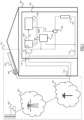
Figure 1 is an exemplificative scenario comprising an electric appliance in which concepts according to embodiments of the present invention can be applied; -
Figure 2 is a very simplified schematic showing the main blocks of a current sensor comprised in the electric appliance ofFigure 1 according to an exemplary embodiment of the present invention, and -
Figure 3 is an equivalent circuit of the current sensor ofFigure 2 and of an electric load of the appliance ofFigure 1 . - Embodiments of the present invention relate to a domestic or commercial (called also professional) electric appliance designed to be supplied with AC current and provided with the capability of monitoring the AC current absorbed by the electric appliance itself (i.e. the overall current consumption of the electric appliance) for obtaining real-time information about its operating condition as well as about the surrounding environment.
- In order to describe advantageous embodiments of the present invention, reference will be now made to the exemplary scenario illustrated in
Figure 1 , wherein anelectric appliance 100, e.g., an electric household appliance - such as a refrigerator, a laundry washing machine, a laundry dryer machine, a combined laundry washing and drying machine, a dishwasher, an oven, an air conditioner and the like - located in abuilding 105, is connected to apower socket 110 for being supplied with AC power. Although inFigure 1 theelectric appliance 100 is an household appliance for the domestic use, similar considerations apply in case theelectric appliance 100 is a commercial (or professional) electric appliance, i.e., an electrical appliance adapted to be employed in commercial (or professional) settings such as in restaurants, refectories, warehouses, laundromats, and the like. - The
electric appliance 100 comprises an ACpower supply input 112 electrically coupled to thepower socket 110, e.g. by means of an AC power cord, for receiving electric power from anAC power source 115. The ACpower supply input 112 preferably comprises a first terminal (line) 113 and a second terminal (neutral) 114. The voltage difference betweenline 113 and neutral 114 oscillates, for example at a frequency of 50 or 60 Hz, causing AC current to flow across a generic electric load when connected betweenline 113 and neutral 114. - In the present document, the term "AC power source" 115 is an umbrella term comprising known means/structures/units/apparatuses for generating and/or transforming, and/or delivering, and/or converting AC electric power; in the example shown in
Figure 1 electric power supplied by theAC power source 115 is available at thepower socket 110. - Making reference to the exemplary scenario illustrated in
Figure 1 , theAC power source 115 is preferably an interconnected network (electric grid) for delivering electricity from suppliers to consumers, which comprises, for example, public availableAC power supplies 120, that produce electrical power, preferably high-voltage transmission grids 122 comprising high-voltage transmission lines for carrying power from the (typically distant) public availableAC power supplies 120 to demand centers, and, preferably, medium-voltage distribution grids 124 for connecting individual customers, such as thebuilding 105 wherein thepower socket 110 is located. The oscillation frequency of voltage difference betweenline 113 and neutral 114 generated by theAC power source 115, e.g., by at least one public availableAC power supply 120, is also referred to as utility frequency. - In the present document, by "public available AC power supply" it is intended any kind of AC power station which is managed by an electric utility and is adapted to generate AC power to be delivered to a plurality of users, for example having made a subscription to such electric utility. Examples of public available AC power supplies may comprise fossil-fuel power stations, nuclear stations, hydro-electric stations, photovoltaic power stations, and the like.
- The
AC power source 115 may advantageously further comprise at least one private available AC power supply 125 - also referred to as additional AC power supply- , such as a renewable power supply, for example a photovoltaic panel or a wind turbine, preferably, but not necessarily, directly located at thebuilding 105 or close to the latter. - In the present document, by "private available AC power supply" it is intended any kind of AC power generator which is directly managed by a private user. Examples of private available AC power supplies 125 may comprise domestic photovoltaic panels and micro-wind turbine generators.
- Such private available
AC power supply 125 is configured to provide additional electric power to be available at thepower socket 110 when such private availableAC power supply 125 is in the condition to operate, e.g., in presence of sun rays or in presence of wind, and when is actually activated. - The
electric appliance 100 comprises one or more electric loads 127 (only one visible inFigure 1 ). - In case the
electric appliance 100 is a refrigerator, possible non limitative examples ofelectric loads 127 may comprise a compressor unit for the circulating refrigerant, an inverter for driving the compressor unit, and a heating resistor for performing defrost cycles. - If the
electric appliance 100 is a laundry washing machine, possible non limitative examples ofelectric loads 127 may comprise a motor for rotating a washer drum, an inverter for driving such motor, a drain pump for draining washing liquid from a washing tub, a recirculation pump for recirculating washing liquid, and a heating resistor for heating washing liquid. - If the
electric appliance 100 is a laundry dyer machine, possible non limitative examples ofelectric loads 127 may comprise a motor for rotating a dryer drum, an inverter for driving such motor, a fan for propelling drying air, a heating resistor for heating drying air, and a compressor for the heat pump circuit. - If the
electric appliance 100 is an oven, possible non limitative examples of electric loads may comprise a heating resistor for heating a cooking chamber, a microwave generator for generating microwaves radiation to be provided in the cooking chamber, and a fan for circulating air inside the cooking chamber. - The generic
electric load 127 is preferably driven by arespective driving apparatus 128 which may advantageously comprise a relay, a TRIAC, or other controllable switching means preferably arranged to selectively couple saidelectric load 127 betweenline 113 and neutral 114, to enable AC current flowing across theelectric load 127. - For example, according to an advantageous embodiment of the present invention, the driving
apparatus 128 has preferably a first conduction terminal electrically coupled to theline 113, preferably a second conduction terminal coupled to a first terminal of the respectiveelectric load 127, and, preferably, a control terminal adapted to receive a control signal CS from a processing unit (control unit) 130 of the appliance 100 (e.g., consisting of or comprising a microprocessor) directed to manage the operation of theappliance 100. Without descending into technical details well known to those skilled in the art, the drivingapparatus 128 is preferably designed to be switched between a non-conductive condition, in which its first conduction terminal is electrically decoupled from its second conduction terminal, and a conductive condition, in which its first conduction terminal is electrically coupled with its second conduction terminal based on the control signal CS received by the drivingapparatus 128. - When the driving
apparatus 128 is in the non-conductive condition, the respectiveelectric load 127 is electrically decoupled from theline 113, and therefore no current flows across it. - When the driving
apparatus 128 is in the conductive condition, the respectiveelectric load 127 is electrically coupled betweenline 113 and neutral 114, so that AC current flows across theelectric load 127 itself. As it is well known to those skilled in the art, if the drivingapparatus 128 is for example a TRIAC, the electric power transferred to theelectric load 127 can be adjusted by setting the control signal CS in such a way to switch the TRIAC in the conductive state at an adjustable time (phase angle) after the start of each half-cycle of the AC voltage difference betweenline 113 and neutral 114, thereby altering the actual voltage difference waveform applied between theelectric load 127 terminals and so changing its RMS (Root Mean Square) effective value. - Clearly, other possible kind and arrangements of driving
apparatus 128 can be used, provided that they are able to selectively allow/prevent the AC current to flow across theelectric load 127. - Also the processing unit (control unit) 130 of the
appliance 100 can be different and/or differently arranged/connected with respect to the one shown inFigure 1 . - The
electric appliance 100 preferably comprises an AC-DC conversion circuit (only conceptually illustrated in the figure and denoted, as a whole, by the reference 140), comprising, for example, transforming, rectifying and regulation components for receiving an AC voltage (e.g., fromline 113 and neutral 114) and providing, for example, one or more DC voltages, such as a ground voltage GND and a DC supply voltage Vcc (e.g., a 3V, 5V or 12V DC voltage with respect to the ground voltage GND). The DC voltage(s) generated by the AC-DC conversion unit 140 can be for example used for supplying - among others - thecontrol unit 130 directed to manage the operation of theappliance 100. - The
electric appliance 100 further comprises acurrent sensor 180 configured to measure, preferably in real-time, the (total) AC current Ip absorbed by theelectric appliance 100 through the power socket 110 (i.e. the overall current consumption of the electric appliance); advantageously thecurrent sensor 180 is configured to provide the outcome of such measure to thecontrol unit 130. As will be described in detail in the following of the present description, thecontrol unit 130 is preferably configured to set the control signal CS - for controlling the driving apparatus 128 - based on the measure carried out by thecurrent sensor 180. - The
current sensor 180 is preferably connected in series to theline 113 at the ACpower supply input 112, preferably in order to be upstream the other elements included in theelectric appliance 100. Preferably, but not necessarily, thecurrent sensor 180 may be supplied with the DC voltages GND and Vcc generated by the AC-DC conversion unit 140. - According to an advantageous embodiment of the present invention, the
current sensor 180 is a current sensor exploiting the Hall effect to measure the AC current absorbed by the electric appliance 100 (i.e. the overall current consumption of the electric appliance). -
Figure 2 is a very simplified schematic showing the main blocks of thecurrent sensor 180 according to an exemplary embodiment of the present invention. Thecurrent sensor 180 preferably comprises aprimary conduction path 210 adapted to be crossed by the AC current Ip absorbed by theelectric appliance 100. The current sensor preferably further comprises an (e.g., integrated)Hall sensor module 220 adapted to sense the magnetic field generated by the passage of the AC current Ip across theprimary conduction path 210 and to generate a corresponding electric signal, for example a corresponding voltage Vp, proportional to the sensed magnetic field. The corresponding electric signal, e.g. voltage Vp, is preferably fed to aconditioning section 230 of the current sensor 180 (preferably comprising filters, amplifiers and offset circuits) for the generation of a corresponding output electric signal, e.g. a corresponding output voltage Vo, that is preferably made available at anoutput terminal 240 of thecurrent sensor 180. The output electric signal, e.g. output voltage Vo generated by theconditioning section 230 is an AC electric signal, e.g., an AC voltage proportional to the AC current Ip, and advantageously follows in real time the oscillations of the latter with the same frequency and phase. In order to maximize the output dynamic, theconditioning section 230 is preferably arranged such as to introduce in the output voltage Vo an offset, preferably equal to half the value of the supply voltage Vcc. - The
output terminal 240 of thecurrent sensor 180 is preferably connected to an analog input terminal of the control unit 130 (seeFigure 1 ) to provide the output voltage Vo to the latter. Thecontrol unit 130 is preferably configured to set the control signal CS for controlling the drivingapparatus 128 based on the received output voltage Vo, as will be described in following portions of the present description. Without descending into particulars well known to those skilled in the art, thecontrol unit 130 may preferably comprise a sampling unit coupled to the analog input terminal for sampling the output voltage Vo received from thecurrent sensor 180; thecontrol unit 130 may preferably comprise an analog-to-digital conversion unit adapted to convert the analog sampled values generated by the sampling unit into digital values which can be processed by other (e.g., firmware, or software) processing modules of thecontrol unit 130. Moreover, similar considerations apply if the output voltage Vo is provided to thecontrol unit 130 in a different way, for example, with a sampling unit and an analog-to-digital conversion unit located outside thecontrol unit 130 itself. - Compared with other known current sensors typically installed in electric appliances - such as the so-called shunt current sensors in which a sensing voltage is generated by amplifying the voltage drop on a resistor ("shunt resistor") in series to the path wherein the current to be sensed is flowing - the
current sensor 180 has a very low input electrical resistance, for example 0.6 mΩ, given by the resistance of theprimary conduction path 210. Thanks to the low input electrical resistance value, thecurrent sensor 180 has a very low power consumption. Moreover, compared to other current sensors, such as the shunt current sensor, thecurrent sensor 180 has theprimary conduction path 210 that is advantageously galvanically insulated from the other parts of thecurrent sensor 180. - Thanks to the
current sensor 180, thecontrol unit 130 is able to monitor, preferably in real-time, the AC current Ip absorbed by the electric appliance 100 (i.e. the overall current consumption of the electric appliance). In this way, thecontrol unit 130 obtains, preferably real-time, information about theelectric appliance 100 operating condition, and preferably also about the surrounding environment, and can control theelectric appliance 100 according to such information. - For example, the
control unit 130 may detect anomalous conditions of theelectric load 127 based on the monitored current Ip. If the current Ip is too high, it may mean that a short-circuit is occurred, or, in case theelectric load 127 is a compressor or a motor, it may mean that the rotor of the compressor or of the motor is blocked. If the current Ip is too low, it may mean the presence of open circuits. In any case, thecontrol unit 130 may use the acknowledged information to inform the user (e.g., through audio and/or visual warning signals) or to take measures (e.g., turning off the electric loads 127). - The
control unit 130 may preferably assess malfunctioning conditions of each individualelectric load 127 of theelectric appliance 100 by considering the monitored current Ip absorbed by the electric appliance 100 (i.e. the overall current consumption of the electric appliance) at the activation of such individualelectric load 127. - By knowing the electrical resistance of the
electric loads 127, thecontrol unit 130 may use the value of the monitored current Ip absorbed by the electric appliance 100 (i.e. the overall current consumption of the electric appliance) for having a, preferably real-time, measurement of the power consumed by theelectric appliance 100, or obtaining measures of the voltage provided by theAC power source 115 at different times, for example for assessing possible anomalous conditions of theAC power source 115. - Preferably, the
control unit 130 may also detect overloads in theAC power source 115 by checking if the utility frequency of the AC power source 115 (and, therefore, of the current Ip) is subjected to drifts. - As can be seen in the equivalent circuit of
Figure 3 , the input resistance of thecurrent sensor 180, identified inFigure 3 with reference R, forms a low-pass filter together with the equivalent capacitance of theelectric loads 127, identified inFigure 3 with reference C. As it is well known to those skilled in the art, the frequency of the main pole of a low-pass filter of this kind is inversely proportional to the value of the resistance R. Therefore, the lower the input resistance R, the wider the range of frequencies which is not filtered out by the low-pass filter. - Since the
current sensor 180 according to the preferred embodiments of the present invention has a low input resistance, thecontrol unit 130 may monitor the current Ip absorbed by the electric appliance 100 (i.e. the overall current consumption of the electric appliance) over a wide range of frequencies. - Making for example reference to an electric load equivalent capacitance C of 300 µF (which is a plausible value for the case in which the
electric load 127 is a compressor of a refrigerator), using thecurrent sensor 180 with an input resistance of 0.6 mΩ forms a low-pass filter having a main pole located at a frequency of about 884 kHz. Therefore, in this exemplary case, thecontrol unit 130 is able to detect components of the current Ip oscillating at frequencies up to 884 kHz. - If a current sensor comprising a shunt resistor was used in place of the
current sensor 180, the main pole would be at a very lower frequency. For example, a typical input resistance of a current sensor comprising a shunt resistor may be 1Ω, and therefore, with a same electric load equivalent capacitance of 300 µF, the main pole would be at a frequency of about 531 Hz. In this case, thecontrol unit 130 would be able to detect components on the current Ip occurring at frequencies up to 531 Hz only (less than three order of magnitude lower than with thecurrent sensor 180 exploiting the Hall effect). - In view of the above, since the
current sensor 180 according to an advantageous embodiments of the present invention has a low input resistance, thecontrol unit 130 is allowed to receive from the current sensor 180 a signal having a harmonic content very similar to the one of the current Ip, because the number of frequency components that are filtered out is strongly reduced. Thanks to this feature, according to an advantageous embodiment of the present invention thecontrol unit 130 is allowed to carry out an harmonic analysis on a signal which is very similar (from the frequency point of view) to the current Ip, comprising a large portion of the whole frequency content of the current Ip (i.e. up to frequencies corresponding to its main pole). If a different current sensor was employed (which is however possible according to the invention) having a higher input resistance, thecontrol unit 130 would receive a signal comprising a lower portion of the whole frequency content of the current Ip (comprising less frequency components), and therefore a harmonic analysis would be less reliable. - According to an advantageous embodiment of the present invention, the
control unit 130 is configured to carry out said harmonic analysis by using frequency domain operations such as the Fast Fourier Transform (FFT), for example implemented by firmware and/or software modules of thecontrol unit 130. - For example, according to an advantageous embodiment of the present invention, the
control unit 130 may assess the presence of secondary components of the monitored current Ip oscillating at frequencies higher than the fundamental frequency (i.e., the utility frequency) of the main component of the monitored current Ip. - As another example, according to an advantageous embodiment of the present invention, the
control unit 130 may calculate the total harmonic distortion THD of the AC current Ip absorbed by theelectric appliance 100 to obtain an accurate measurement of the harmonic distortion present (e.g. the ratio of the sum of the powers of all harmonic components to the power of the fundamental frequency of the AC current Ip). - Based on the outcome of the harmonic analysis (e.g. the assessment of secondary components and/or the calculation of the total harmonic distortion THD), the
control unit 130 according to embodiments of the present invention can detect malfunctioning conditions of theelectric loads 127, for example a compressor motor bad condition or a compressor inverter failure, and detect disturbances on theAC power source 115 caused by other electric appliances fed by the sameAC power source 115. - For example, according to an advantageous embodiment of the present invention, through the harmonic analysis, e.g. carried out by means of a FFT, the
control unit 130 may detect spurious frequency contents on the spectrum of the AC current Ip (carrier or modulation). If spurious frequency contents are detected, thecontrol unit 130 may diagnose a malfunctioning condition of theelectric loads 127, such as an inverter malfunction - i.e., a partially damaged driver - or an incorrect motor condition. - According to an advantageous embodiment of the present invention, the harmonic analysis carried out on a signal having a harmonic content very similar to the one of the current Ip, made possible by having the low input resistance
current sensor 180, can be advantageously exploited for assessing, preferably in real time, whether there are private available AC power supplies, such as the renewable power supply 125 (e.g., photovoltaic panel) ofFigure 1 , which are providing additional electric power or not. - Making reference to
Figure 1 , therenewable power supply 125 may preferably comprise amodulator unit 190 adapted to modulate the AC current generated by therenewable power supply 125 itself with an AC identification signal oscillating at a higher frequency (such as for example in the range 30 - 300 KHz) when therenewable power supply 125 is operating and is delivering additional electric power. - In this way, according to an advantageous embodiment of the present invention, if the results of the harmonic analysis carried out on the AC current Ip absorbed by the
electric appliance 100 provides that the AC current Ip comprises a component oscillating at the frequency of a known identification signal, thecontrol unit 130 may assess that therenewable power supply 125 corresponding to said specific identification signal is currently delivering electric power. Moreover, thecontrol unit 130 may also advantageously comprise a demodulation unit configured for demodulating Power Line Communication (PLC) signals transmitted by the private available AC power supplies, such as therenewable power supply 125. - According to an advantageous embodiment of the present invention, the possibility of knowing, preferably in real time, if renewable power supplies 125 are currently delivering electric power or not, can be advantageously exploited to program the operation of the
electric appliance 100 according to an optimized schedule, for example to reduce costs. For example, if theelectric appliance 100 is a washing machine, the execution of a washing cycle may be temporarily paused by thecontrol unit 130 until arenewable power supply 125 is assessed to be actually delivering additional electric power. - Naturally, in order to satisfy local and specific requirements, a person skilled in the art may apply to the solution described above many logical and/or physical modifications and alterations. Moreover, it is expressly intended that specific elements and/or method steps described in connection with any disclosed embodiment of the invention may be incorporated in any other embodiment.
- For example, even if in the description reference has been explicitly made to the use of a current sensor configured to exploit the Hall effect, the concepts of the present invention can be applied to other types of current sensors adapted to measure the (total) AC current absorbed by the electric appliance (i.e. the overall current consumption of the electric appliance), provided that the input resistance thereof is sufficiently low (e.g., from 0,1 to 1 mΩ) to generate a corresponding signal to be provided to the control unit having a harmonic content sufficiently similar to the one of the current absorbed by the electric appliance.
Claims (13)
- A domestic or commercial electric appliance (100) comprising:- at least one electric load (127);- an AC power supply input (112) connectable to an AC power source (115) for receiving electric power from said power source (115) and arranged to supply electric power to said at least one electric load (127), the AC power source comprising a private available AC power supply (125) connected to said AC
power supply unit (112), wherein the private available AC power supply is an AC power generator which is directly managed by a private user, comprises a modulator unit adapted to modulate AC current generated by the private AC power supply with an identification signal when the AC power generator is operating and delivering additional power and further comprises a domestic photovoltaic panel or a micro-wind turbine generator;- a current sensor (180) for sensing an AC current absorbed by the electric appliance from the AC power source; and- a processing unit (130) for carrying out an harmonic analysis on a sensed AC current sensed by the current sensor (180) and for driving the at least one electric load (127) based on an outcome of said harmonic analysis, wherein said processing unit (130) is configured to assess a presence, in a sensed AC current, of at least one secondary component oscillating at a frequency higher than a fundamental frequency of a main component of said sensed AC current, and to detect if said at least one secondary component corresponds to an identification signal generated by the private available AC power supply (125), wherein the processing unit (130) is further configured to drive said at least one electric load (127) based on said identification signal. - A domestic or commercial electric appliance (100) according to claim 1, wherein said current sensor is a Hall current sensor.
- The domestic or commercial electric appliance (100) of claim 1 or 2, wherein the processing unit (130) is configured to calculate the total harmonic distortion of the sensed AC current, and to assess at least one among:- malfunctioning conditions of the at least one electric load (127), and- disturbances on the AC power source caused by other electric appliances,based on the calculated total harmonic distortion.
- The domestic or commercial electric appliance (100) of any one among the preceding claims, wherein the processing unit (130) is configured to carry out the harmonic analysis on the sensed AC current by applying a Fast Fourier Transform to the sensed AC current.
- The domestic or commercial electric appliance (100) of any one among the preceding claims, wherein the processing unit (130) is configured to assess anomalous operation conditions or malfunction conditions of the at least one electric load (127) based on the sensed AC current.
- The domestic or commercial electric appliance (100) of any one among the preceding claims, wherein the processing unit (130) is further configured to assess the electric power consumption of the at least one electric load (127) based on the sensed AC current.
- The domestic or commercial electric appliance (100) of any one among the preceding claims, wherein the processing unit (130) is further configured to assess an overload condition of the AC power source (115) based on sensed AC current.
- The domestic or commercial electric appliance (100) of any one among the preceding claims, wherein said electric appliance is a refrigerator, and wherein said at least one electric load (127) comprise at least one among:- an inverter unit;- a compressor unit;- a defrost heating resistor.
- The domestic or commercial electric appliance (100) of any one among the preceding claims, wherein said electric appliance is a laundry washing machine, and wherein said at least one electric load (127) comprises at least one among:- a drain pump;- a recirculation pump;- an drum motor circuit;- a heating resistor.
- The domestic or commercial electric appliance (100) of any one among the preceding claims, wherein said electric appliance is a laundry dryer machine, and wherein said at least one electric load (127) comprises at least one among:- an drum motor circuit;- a heating resistor;- a compressor unit;- a fan.
- The domestic or commercial electric appliance (100) of any one among the preceding claims, wherein said electric appliance is an oven, and wherein said at least one electric load (127) comprises at least one among:- a heating resistor;- a microwave generator unit;- a fan.
- An electric system (150) comprising a domestic or commercial electric appliance (100) according to any one among the preceding claims and an AC power source (115) connected to the AC power supply input (112) of said domestic or commercial electric appliance (100), wherein said AC power source (115) is adapted to provide to said AC power supply input (112) an electric power having a fundamental frequency being an utility frequency of a public available AC power supply (120)
- The electric system (150) of claim 12, wherein:- said AC power source (115) includes at least one private available AC power supply (125), wherein the private available AC power supply is an AC power generator which is directly managed by a private user and each private available AC power supply being configured to generate additional electric power and a corresponding identification signal when activated.
Applications Claiming Priority (1)
| Application Number | Priority Date | Filing Date | Title |
|---|---|---|---|
| PCT/EP2016/077673 WO2018091067A1 (en) | 2016-11-15 | 2016-11-15 | Monitoring arrangement for domestic or commercial electrical appliances |
Publications (2)
| Publication Number | Publication Date |
|---|---|
| EP3542433A1 EP3542433A1 (en) | 2019-09-25 |
| EP3542433B1 true EP3542433B1 (en) | 2023-06-28 |
Family
ID=57396407
Family Applications (1)
| Application Number | Title | Priority Date | Filing Date |
|---|---|---|---|
| EP16801403.3A Active EP3542433B1 (en) | 2016-11-15 | 2016-11-15 | Monitoring arrangement for domestic or commercial electrical appliances |
Country Status (7)
| Country | Link |
|---|---|
| US (1) | US20200057098A1 (en) |
| EP (1) | EP3542433B1 (en) |
| KR (1) | KR102587394B1 (en) |
| CN (1) | CN110024251B (en) |
| AU (1) | AU2016429639A1 (en) |
| BR (1) | BR112019009585A2 (en) |
| WO (1) | WO2018091067A1 (en) |
Families Citing this family (3)
| Publication number | Priority date | Publication date | Assignee | Title |
|---|---|---|---|---|
| CN112631242A (en) * | 2020-12-07 | 2021-04-09 | 国网四川省电力公司电力科学研究院 | Power abuse analysis method and device for household electrical equipment |
| US20240373520A1 (en) | 2021-04-08 | 2024-11-07 | Electrolux Appliances Aktiebolag | Household appliance and operating method thereof |
| KR102665464B1 (en) * | 2021-05-04 | 2024-05-13 | 한국전자통신연구원 | Method for identifying applications by analyzing the harmonics of power signal and devices performing the same |
Family Cites Families (30)
| Publication number | Priority date | Publication date | Assignee | Title |
|---|---|---|---|---|
| US4615179A (en) | 1985-01-17 | 1986-10-07 | General Electric Company | Defrost diagnostic arrangement for self-defrosting refrigerator appliance |
| US4741170A (en) | 1986-12-22 | 1988-05-03 | Whirlpool Corporation | Fault tolerant control for a refrigerator |
| CA2008705C (en) * | 1989-04-17 | 1994-07-26 | Craig J. Nordby | Drive system for household appliances |
| GB9616157D0 (en) * | 1996-08-01 | 1996-09-11 | Switched Reluctance Drives Ltd | Current transducer |
| CA2212504C (en) * | 1996-08-09 | 2004-11-16 | Mesta Electronics, Inc. | Active harmonic filter and power factor corrector |
| JP2000074977A (en) * | 1998-09-03 | 2000-03-14 | Jidosha Denki Kogyo Co Ltd | Current-detecting apparatus |
| IT1310142B1 (en) * | 1999-08-20 | 2002-02-11 | Merloni Elettrodomestici Spa | DEVICE, SYSTEM AND METHOD FOR THE MONITORING OF A DOMESTIC ELECTRICITY USE, IN PARTICULAR A HOUSEHOLD APPLIANCE. |
| US6816078B2 (en) * | 2000-04-12 | 2004-11-09 | Central Research Institute Of Electric Power Industry | System and method for estimating power consumption of electric apparatus, and abnormality alarm system utilizing the same |
| JP4084966B2 (en) | 2002-07-05 | 2008-04-30 | 財団法人電力中央研究所 | Method and system for estimating operating state of specified electrical equipment and method and system for confirming safety of occupants of electric power consumers |
| JP3825020B2 (en) * | 2002-08-01 | 2006-09-20 | 株式会社アイ・ヒッツ研究所 | Distributed power supply system |
| DE602004023614D1 (en) * | 2003-07-09 | 2009-11-26 | Isra Juk Electronics Ltd | SYSTEM AND METHOD FOR DETECTING ELECTRICAL ERRORS |
| ITTO20060447A1 (en) * | 2006-06-16 | 2007-12-17 | Indesit Co Spa | ELECTRIC USERS, PARTICULARLY A HOME APPLIANCE, AND SYSTEM INCLUDING SUCH UTILITY |
| CN101017982A (en) * | 2007-03-12 | 2007-08-15 | 刘建政 | Light voltage and wind power integrated networking device with the reactive power compensation and harmonious administration function |
| US7969156B2 (en) * | 2007-03-30 | 2011-06-28 | Liebert Corporation | Method and apparatus for monitoring a load |
| EP2304452A4 (en) * | 2008-04-14 | 2014-12-03 | Corp Nuvolt Inc | Electrical anomaly detection method and system |
| EP2389617A4 (en) | 2009-01-26 | 2015-02-25 | Geneva Cleantech Inc | MONITORING ENERGY CONSUMPTION WITH REMOTE DISPLAY AND AUTOMATIC DEVICE DETECTION INCLUDING GRAPHICAL USER INTERFACE |
| BR112013003213A2 (en) * | 2010-08-10 | 2016-05-17 | Sensus Usa Inc | data processing system, electrical meter and method of analyzing the energy consumption of a facility having a plurality of electrical charges |
| DE102011017574A1 (en) * | 2011-04-27 | 2012-10-31 | BSH Bosch und Siemens Hausgeräte GmbH | Energy consumption determination for household appliances in a combination of several home appliances that form a system, and associated method |
| SE536142C2 (en) * | 2011-11-25 | 2013-05-28 | Comsys Ab | Active filter for resonance reduction |
| US9030793B2 (en) * | 2012-04-13 | 2015-05-12 | General Electric Company | Method, device, and system for monitoring current provided to a load |
| KR101893150B1 (en) * | 2012-06-12 | 2018-08-30 | 엘지전자 주식회사 | A home appliance having a built-in power meter |
| TWI617110B (en) * | 2012-10-07 | 2018-03-01 | 旭辰資訊股份有限公司 | Concentrated energy saving method of total dc power consumption control |
| CN103001230B (en) * | 2012-11-16 | 2014-10-15 | 天津大学 | Non-invasive power load monitoring and decomposing current mode matching method |
| US9025287B2 (en) * | 2012-12-19 | 2015-05-05 | Stmicroelectronics S.R.L. | Arc fault detection equipment and method using low frequency harmonic current analysis |
| EP2784523B1 (en) * | 2013-03-28 | 2020-02-19 | Electrolux Appliances Aktiebolag | Method and circuit for determining dispersion of electric power towards ground in electric appliances |
| TWI504905B (en) * | 2013-06-04 | 2015-10-21 | Univ Nat Taiwan Science Tech | Non-intrusive load monitoring method and device |
| WO2015059272A1 (en) * | 2013-10-24 | 2015-04-30 | Universite Libre De Bruxelles | Improved non-intrusive appliance load monitoring method and device |
| US20160087442A1 (en) * | 2014-07-04 | 2016-03-24 | Stefan Matan | Modular power grid |
| US11063431B2 (en) * | 2014-07-04 | 2021-07-13 | Apparent Labs Llc | Hierarchical and distributed power grid control |
| US9369782B2 (en) * | 2014-09-17 | 2016-06-14 | Neurio Technology Inc. | On-board feature extraction and selection from high frequency electricity consumption data |
-
2016
- 2016-11-15 US US16/349,828 patent/US20200057098A1/en not_active Abandoned
- 2016-11-15 WO PCT/EP2016/077673 patent/WO2018091067A1/en not_active Ceased
- 2016-11-15 CN CN201680090660.0A patent/CN110024251B/en active Active
- 2016-11-15 EP EP16801403.3A patent/EP3542433B1/en active Active
- 2016-11-15 KR KR1020197016290A patent/KR102587394B1/en active Active
- 2016-11-15 AU AU2016429639A patent/AU2016429639A1/en not_active Abandoned
- 2016-11-15 BR BR112019009585A patent/BR112019009585A2/en not_active Application Discontinuation
Also Published As
| Publication number | Publication date |
|---|---|
| KR20190084079A (en) | 2019-07-15 |
| AU2016429639A1 (en) | 2019-05-02 |
| WO2018091067A1 (en) | 2018-05-24 |
| US20200057098A1 (en) | 2020-02-20 |
| EP3542433A1 (en) | 2019-09-25 |
| KR102587394B1 (en) | 2023-10-10 |
| CN110024251B (en) | 2023-09-08 |
| BR112019009585A2 (en) | 2019-08-13 |
| CN110024251A (en) | 2019-07-16 |
Similar Documents
| Publication | Publication Date | Title |
|---|---|---|
| US8319599B2 (en) | Electrical appliance, in particular an electrical household appliance, a corresponding optional auxiliary device, and a system comprising said appliance and device | |
| EP2674768B1 (en) | Home appliance having built-in consumption meter | |
| RU2725023C1 (en) | Method of monitoring and controlling consumption of electric energy by consumers in a home and a complex for its implementation | |
| CN107453483A (en) | A kind of dispatching of power netwoks control system | |
| WO2013144947A2 (en) | System and method for managing electric grid power supply | |
| KR20150127029A (en) | Power grid load monitor and shed control | |
| EP3542433B1 (en) | Monitoring arrangement for domestic or commercial electrical appliances | |
| US11139656B2 (en) | Power supply arrangement | |
| CN103004054B (en) | Be the method that household electrical appliance are powered and the household electrical appliance being suitable for performing described method by low-voltage power network | |
| Goldin et al. | Design and validation of a power modulation system for residential demand-side management | |
| Kul et al. | Energy saving IoT-based advanced load limiter | |
| JP2013099058A (en) | Power conditioner | |
| EP4320450B1 (en) | Household appliance and operating method thereof | |
| Dhongade et al. | The study on consumption of household appliances with SCADA platform | |
| Falvo et al. | Smart n-grid energy management with an open UPQC | |
| GB2508479A (en) | Transferring Excess Renewable Power to an Energy Storage | |
| Batzelis et al. | Off-grid inverter faults: diagnosis, symptoms and cause of failure | |
| Goldin et al. | The “smart dim fuse”: A new approach to load control as a distributed energy resource | |
| HK1239957A1 (en) | Power supply arrangement | |
| CN109936168A (en) | A kind of inverter and its operation method and controller | |
| Mamlook et al. | Controlling future intelligent smart homes using wireless integrated network systems | |
| Turner | One phase or three: Configuring multi-phase at home | |
| Anderson et al. | Improving the efficiency of residential HVAC systems using computer-based power-electronic controls | |
| Micheletti et al. | Instantaneous average active power measurement for building energy management system | |
| DE102019105640A1 (en) | METHOD FOR CONTROLLING DEVICES |
Legal Events
| Date | Code | Title | Description |
|---|---|---|---|
| STAA | Information on the status of an ep patent application or granted ep patent |
Free format text: STATUS: UNKNOWN |
|
| STAA | Information on the status of an ep patent application or granted ep patent |
Free format text: STATUS: THE INTERNATIONAL PUBLICATION HAS BEEN MADE |
|
| PUAI | Public reference made under article 153(3) epc to a published international application that has entered the european phase |
Free format text: ORIGINAL CODE: 0009012 |
|
| STAA | Information on the status of an ep patent application or granted ep patent |
Free format text: STATUS: REQUEST FOR EXAMINATION WAS MADE |
|
| 17P | Request for examination filed |
Effective date: 20190617 |
|
| AK | Designated contracting states |
Kind code of ref document: A1 Designated state(s): AL AT BE BG CH CY CZ DE DK EE ES FI FR GB GR HR HU IE IS IT LI LT LU LV MC MK MT NL NO PL PT RO RS SE SI SK SM TR |
|
| AX | Request for extension of the european patent |
Extension state: BA ME |
|
| DAV | Request for validation of the european patent (deleted) | ||
| DAX | Request for extension of the european patent (deleted) | ||
| STAA | Information on the status of an ep patent application or granted ep patent |
Free format text: STATUS: EXAMINATION IS IN PROGRESS |
|
| 17Q | First examination report despatched |
Effective date: 20201009 |
|
| GRAP | Despatch of communication of intention to grant a patent |
Free format text: ORIGINAL CODE: EPIDOSNIGR1 |
|
| STAA | Information on the status of an ep patent application or granted ep patent |
Free format text: STATUS: GRANT OF PATENT IS INTENDED |
|
| INTG | Intention to grant announced |
Effective date: 20230131 |
|
| GRAS | Grant fee paid |
Free format text: ORIGINAL CODE: EPIDOSNIGR3 |
|
| GRAA | (expected) grant |
Free format text: ORIGINAL CODE: 0009210 |
|
| STAA | Information on the status of an ep patent application or granted ep patent |
Free format text: STATUS: THE PATENT HAS BEEN GRANTED |
|
| AK | Designated contracting states |
Kind code of ref document: B1 Designated state(s): AL AT BE BG CH CY CZ DE DK EE ES FI FR GB GR HR HU IE IS IT LI LT LU LV MC MK MT NL NO PL PT RO RS SE SI SK SM TR |
|
| REG | Reference to a national code |
Ref country code: CH Ref legal event code: EP |
|
| REG | Reference to a national code |
Ref country code: AT Ref legal event code: REF Ref document number: 1583598 Country of ref document: AT Kind code of ref document: T Effective date: 20230715 |
|
| REG | Reference to a national code |
Ref country code: IE Ref legal event code: FG4D |
|
| REG | Reference to a national code |
Ref country code: DE Ref legal event code: R096 Ref document number: 602016080662 Country of ref document: DE |
|
| P01 | Opt-out of the competence of the unified patent court (upc) registered |
Effective date: 20230707 |
|
| REG | Reference to a national code |
Ref country code: LT Ref legal event code: MG9D |
|
| PG25 | Lapsed in a contracting state [announced via postgrant information from national office to epo] |
Ref country code: SE Free format text: LAPSE BECAUSE OF FAILURE TO SUBMIT A TRANSLATION OF THE DESCRIPTION OR TO PAY THE FEE WITHIN THE PRESCRIBED TIME-LIMIT Effective date: 20230628 Ref country code: NO Free format text: LAPSE BECAUSE OF FAILURE TO SUBMIT A TRANSLATION OF THE DESCRIPTION OR TO PAY THE FEE WITHIN THE PRESCRIBED TIME-LIMIT Effective date: 20230928 |
|
| REG | Reference to a national code |
Ref country code: NL Ref legal event code: MP Effective date: 20230628 |
|
| REG | Reference to a national code |
Ref country code: AT Ref legal event code: MK05 Ref document number: 1583598 Country of ref document: AT Kind code of ref document: T Effective date: 20230628 |
|
| PG25 | Lapsed in a contracting state [announced via postgrant information from national office to epo] |
Ref country code: RS Free format text: LAPSE BECAUSE OF FAILURE TO SUBMIT A TRANSLATION OF THE DESCRIPTION OR TO PAY THE FEE WITHIN THE PRESCRIBED TIME-LIMIT Effective date: 20230628 Ref country code: NL Free format text: LAPSE BECAUSE OF FAILURE TO SUBMIT A TRANSLATION OF THE DESCRIPTION OR TO PAY THE FEE WITHIN THE PRESCRIBED TIME-LIMIT Effective date: 20230628 Ref country code: LV Free format text: LAPSE BECAUSE OF FAILURE TO SUBMIT A TRANSLATION OF THE DESCRIPTION OR TO PAY THE FEE WITHIN THE PRESCRIBED TIME-LIMIT Effective date: 20230628 Ref country code: LT Free format text: LAPSE BECAUSE OF FAILURE TO SUBMIT A TRANSLATION OF THE DESCRIPTION OR TO PAY THE FEE WITHIN THE PRESCRIBED TIME-LIMIT Effective date: 20230628 Ref country code: HR Free format text: LAPSE BECAUSE OF FAILURE TO SUBMIT A TRANSLATION OF THE DESCRIPTION OR TO PAY THE FEE WITHIN THE PRESCRIBED TIME-LIMIT Effective date: 20230628 Ref country code: GR Free format text: LAPSE BECAUSE OF FAILURE TO SUBMIT A TRANSLATION OF THE DESCRIPTION OR TO PAY THE FEE WITHIN THE PRESCRIBED TIME-LIMIT Effective date: 20230929 |
|
| PG25 | Lapsed in a contracting state [announced via postgrant information from national office to epo] |
Ref country code: FI Free format text: LAPSE BECAUSE OF FAILURE TO SUBMIT A TRANSLATION OF THE DESCRIPTION OR TO PAY THE FEE WITHIN THE PRESCRIBED TIME-LIMIT Effective date: 20230628 |
|
| PG25 | Lapsed in a contracting state [announced via postgrant information from national office to epo] |
Ref country code: SK Free format text: LAPSE BECAUSE OF FAILURE TO SUBMIT A TRANSLATION OF THE DESCRIPTION OR TO PAY THE FEE WITHIN THE PRESCRIBED TIME-LIMIT Effective date: 20230628 |
|
| PG25 | Lapsed in a contracting state [announced via postgrant information from national office to epo] |
Ref country code: ES Free format text: LAPSE BECAUSE OF FAILURE TO SUBMIT A TRANSLATION OF THE DESCRIPTION OR TO PAY THE FEE WITHIN THE PRESCRIBED TIME-LIMIT Effective date: 20230628 |
|
| PG25 | Lapsed in a contracting state [announced via postgrant information from national office to epo] |
Ref country code: IS Free format text: LAPSE BECAUSE OF FAILURE TO SUBMIT A TRANSLATION OF THE DESCRIPTION OR TO PAY THE FEE WITHIN THE PRESCRIBED TIME-LIMIT Effective date: 20231028 |
|
| PG25 | Lapsed in a contracting state [announced via postgrant information from national office to epo] |
Ref country code: SM Free format text: LAPSE BECAUSE OF FAILURE TO SUBMIT A TRANSLATION OF THE DESCRIPTION OR TO PAY THE FEE WITHIN THE PRESCRIBED TIME-LIMIT Effective date: 20230628 Ref country code: SK Free format text: LAPSE BECAUSE OF FAILURE TO SUBMIT A TRANSLATION OF THE DESCRIPTION OR TO PAY THE FEE WITHIN THE PRESCRIBED TIME-LIMIT Effective date: 20230628 Ref country code: RO Free format text: LAPSE BECAUSE OF FAILURE TO SUBMIT A TRANSLATION OF THE DESCRIPTION OR TO PAY THE FEE WITHIN THE PRESCRIBED TIME-LIMIT Effective date: 20230628 Ref country code: PT Free format text: LAPSE BECAUSE OF FAILURE TO SUBMIT A TRANSLATION OF THE DESCRIPTION OR TO PAY THE FEE WITHIN THE PRESCRIBED TIME-LIMIT Effective date: 20231030 Ref country code: IS Free format text: LAPSE BECAUSE OF FAILURE TO SUBMIT A TRANSLATION OF THE DESCRIPTION OR TO PAY THE FEE WITHIN THE PRESCRIBED TIME-LIMIT Effective date: 20231028 Ref country code: ES Free format text: LAPSE BECAUSE OF FAILURE TO SUBMIT A TRANSLATION OF THE DESCRIPTION OR TO PAY THE FEE WITHIN THE PRESCRIBED TIME-LIMIT Effective date: 20230628 Ref country code: EE Free format text: LAPSE BECAUSE OF FAILURE TO SUBMIT A TRANSLATION OF THE DESCRIPTION OR TO PAY THE FEE WITHIN THE PRESCRIBED TIME-LIMIT Effective date: 20230628 Ref country code: CZ Free format text: LAPSE BECAUSE OF FAILURE TO SUBMIT A TRANSLATION OF THE DESCRIPTION OR TO PAY THE FEE WITHIN THE PRESCRIBED TIME-LIMIT Effective date: 20230628 Ref country code: AT Free format text: LAPSE BECAUSE OF FAILURE TO SUBMIT A TRANSLATION OF THE DESCRIPTION OR TO PAY THE FEE WITHIN THE PRESCRIBED TIME-LIMIT Effective date: 20230628 |
|
| PG25 | Lapsed in a contracting state [announced via postgrant information from national office to epo] |
Ref country code: PL Free format text: LAPSE BECAUSE OF FAILURE TO SUBMIT A TRANSLATION OF THE DESCRIPTION OR TO PAY THE FEE WITHIN THE PRESCRIBED TIME-LIMIT Effective date: 20230628 |
|
| REG | Reference to a national code |
Ref country code: DE Ref legal event code: R097 Ref document number: 602016080662 Country of ref document: DE |
|
| PG25 | Lapsed in a contracting state [announced via postgrant information from national office to epo] |
Ref country code: DK Free format text: LAPSE BECAUSE OF FAILURE TO SUBMIT A TRANSLATION OF THE DESCRIPTION OR TO PAY THE FEE WITHIN THE PRESCRIBED TIME-LIMIT Effective date: 20230628 |
|
| PLBE | No opposition filed within time limit |
Free format text: ORIGINAL CODE: 0009261 |
|
| STAA | Information on the status of an ep patent application or granted ep patent |
Free format text: STATUS: NO OPPOSITION FILED WITHIN TIME LIMIT |
|
| PG25 | Lapsed in a contracting state [announced via postgrant information from national office to epo] |
Ref country code: IT Free format text: LAPSE BECAUSE OF FAILURE TO SUBMIT A TRANSLATION OF THE DESCRIPTION OR TO PAY THE FEE WITHIN THE PRESCRIBED TIME-LIMIT Effective date: 20230628 |
|
| 26N | No opposition filed |
Effective date: 20240402 |
|
| REG | Reference to a national code |
Ref country code: CH Ref legal event code: PL |
|
| PG25 | Lapsed in a contracting state [announced via postgrant information from national office to epo] |
Ref country code: MC Free format text: LAPSE BECAUSE OF FAILURE TO SUBMIT A TRANSLATION OF THE DESCRIPTION OR TO PAY THE FEE WITHIN THE PRESCRIBED TIME-LIMIT Effective date: 20230628 |
|
| PG25 | Lapsed in a contracting state [announced via postgrant information from national office to epo] |
Ref country code: LU Free format text: LAPSE BECAUSE OF NON-PAYMENT OF DUE FEES Effective date: 20231115 |
|
| PG25 | Lapsed in a contracting state [announced via postgrant information from national office to epo] |
Ref country code: CH Free format text: LAPSE BECAUSE OF NON-PAYMENT OF DUE FEES Effective date: 20231130 |
|
| PG25 | Lapsed in a contracting state [announced via postgrant information from national office to epo] |
Ref country code: MC Free format text: LAPSE BECAUSE OF FAILURE TO SUBMIT A TRANSLATION OF THE DESCRIPTION OR TO PAY THE FEE WITHIN THE PRESCRIBED TIME-LIMIT Effective date: 20230628 Ref country code: LU Free format text: LAPSE BECAUSE OF NON-PAYMENT OF DUE FEES Effective date: 20231115 Ref country code: CH Free format text: LAPSE BECAUSE OF NON-PAYMENT OF DUE FEES Effective date: 20231130 Ref country code: SI Free format text: LAPSE BECAUSE OF FAILURE TO SUBMIT A TRANSLATION OF THE DESCRIPTION OR TO PAY THE FEE WITHIN THE PRESCRIBED TIME-LIMIT Effective date: 20230628 |
|
| REG | Reference to a national code |
Ref country code: BE Ref legal event code: MM Effective date: 20231130 |
|
| REG | Reference to a national code |
Ref country code: IE Ref legal event code: MM4A |
|
| PG25 | Lapsed in a contracting state [announced via postgrant information from national office to epo] |
Ref country code: IE Free format text: LAPSE BECAUSE OF NON-PAYMENT OF DUE FEES Effective date: 20231115 |
|
| PG25 | Lapsed in a contracting state [announced via postgrant information from national office to epo] |
Ref country code: BE Free format text: LAPSE BECAUSE OF NON-PAYMENT OF DUE FEES Effective date: 20231130 |
|
| PG25 | Lapsed in a contracting state [announced via postgrant information from national office to epo] |
Ref country code: IE Free format text: LAPSE BECAUSE OF NON-PAYMENT OF DUE FEES Effective date: 20231115 Ref country code: BE Free format text: LAPSE BECAUSE OF NON-PAYMENT OF DUE FEES Effective date: 20231130 |
|
| PG25 | Lapsed in a contracting state [announced via postgrant information from national office to epo] |
Ref country code: BG Free format text: LAPSE BECAUSE OF FAILURE TO SUBMIT A TRANSLATION OF THE DESCRIPTION OR TO PAY THE FEE WITHIN THE PRESCRIBED TIME-LIMIT Effective date: 20230628 |
|
| PG25 | Lapsed in a contracting state [announced via postgrant information from national office to epo] |
Ref country code: BG Free format text: LAPSE BECAUSE OF FAILURE TO SUBMIT A TRANSLATION OF THE DESCRIPTION OR TO PAY THE FEE WITHIN THE PRESCRIBED TIME-LIMIT Effective date: 20230628 |
|
| PG25 | Lapsed in a contracting state [announced via postgrant information from national office to epo] |
Ref country code: CY Free format text: LAPSE BECAUSE OF FAILURE TO SUBMIT A TRANSLATION OF THE DESCRIPTION OR TO PAY THE FEE WITHIN THE PRESCRIBED TIME-LIMIT; INVALID AB INITIO Effective date: 20161115 |
|
| PG25 | Lapsed in a contracting state [announced via postgrant information from national office to epo] |
Ref country code: HU Free format text: LAPSE BECAUSE OF FAILURE TO SUBMIT A TRANSLATION OF THE DESCRIPTION OR TO PAY THE FEE WITHIN THE PRESCRIBED TIME-LIMIT; INVALID AB INITIO Effective date: 20161115 |
|
| PG25 | Lapsed in a contracting state [announced via postgrant information from national office to epo] |
Ref country code: TR Free format text: LAPSE BECAUSE OF FAILURE TO SUBMIT A TRANSLATION OF THE DESCRIPTION OR TO PAY THE FEE WITHIN THE PRESCRIBED TIME-LIMIT Effective date: 20230628 |
|
| PGFP | Annual fee paid to national office [announced via postgrant information from national office to epo] |
Ref country code: DE Payment date: 20251126 Year of fee payment: 10 |
|
| PGFP | Annual fee paid to national office [announced via postgrant information from national office to epo] |
Ref country code: GB Payment date: 20251125 Year of fee payment: 10 |
|
| PGFP | Annual fee paid to national office [announced via postgrant information from national office to epo] |
Ref country code: FR Payment date: 20251124 Year of fee payment: 10 |