EP3542070B1 - Virole antigivre de compresseur de turbomachine axiale - Google Patents
Virole antigivre de compresseur de turbomachine axiale Download PDFInfo
- Publication number
- EP3542070B1 EP3542070B1 EP17801024.5A EP17801024A EP3542070B1 EP 3542070 B1 EP3542070 B1 EP 3542070B1 EP 17801024 A EP17801024 A EP 17801024A EP 3542070 B1 EP3542070 B1 EP 3542070B1
- Authority
- EP
- European Patent Office
- Prior art keywords
- layer
- abradable
- ferrule
- turbomachine
- heater module
- Prior art date
- Legal status (The legal status is an assumption and is not a legal conclusion. Google has not performed a legal analysis and makes no representation as to the accuracy of the status listed.)
- Active
Links
Images


Classifications
-
- F—MECHANICAL ENGINEERING; LIGHTING; HEATING; WEAPONS; BLASTING
- F01—MACHINES OR ENGINES IN GENERAL; ENGINE PLANTS IN GENERAL; STEAM ENGINES
- F01D—NON-POSITIVE DISPLACEMENT MACHINES OR ENGINES, e.g. STEAM TURBINES
- F01D11/00—Preventing or minimising internal leakage of working-fluid, e.g. between stages
- F01D11/001—Preventing or minimising internal leakage of working-fluid, e.g. between stages for sealing space between stator blade and rotor
-
- F—MECHANICAL ENGINEERING; LIGHTING; HEATING; WEAPONS; BLASTING
- F01—MACHINES OR ENGINES IN GENERAL; ENGINE PLANTS IN GENERAL; STEAM ENGINES
- F01D—NON-POSITIVE DISPLACEMENT MACHINES OR ENGINES, e.g. STEAM TURBINES
- F01D11/00—Preventing or minimising internal leakage of working-fluid, e.g. between stages
- F01D11/08—Preventing or minimising internal leakage of working-fluid, e.g. between stages for sealing space between rotor blade tips and stator
- F01D11/12—Preventing or minimising internal leakage of working-fluid, e.g. between stages for sealing space between rotor blade tips and stator using a rubstrip, e.g. erodible. deformable or resiliently-biased part
- F01D11/122—Preventing or minimising internal leakage of working-fluid, e.g. between stages for sealing space between rotor blade tips and stator using a rubstrip, e.g. erodible. deformable or resiliently-biased part with erodable or abradable material
-
- F—MECHANICAL ENGINEERING; LIGHTING; HEATING; WEAPONS; BLASTING
- F01—MACHINES OR ENGINES IN GENERAL; ENGINE PLANTS IN GENERAL; STEAM ENGINES
- F01D—NON-POSITIVE DISPLACEMENT MACHINES OR ENGINES, e.g. STEAM TURBINES
- F01D25/00—Component parts, details, or accessories, not provided for in, or of interest apart from, other groups
- F01D25/02—De-icing means for engines having icing phenomena
-
- F—MECHANICAL ENGINEERING; LIGHTING; HEATING; WEAPONS; BLASTING
- F02—COMBUSTION ENGINES; HOT-GAS OR COMBUSTION-PRODUCT ENGINE PLANTS
- F02C—GAS-TURBINE PLANTS; AIR INTAKES FOR JET-PROPULSION PLANTS; CONTROLLING FUEL SUPPLY IN AIR-BREATHING JET-PROPULSION PLANTS
- F02C7/00—Features, components parts, details or accessories, not provided for in, or of interest apart form groups F02C1/00 - F02C6/00; Air intakes for jet-propulsion plants
- F02C7/04—Air intakes for gas-turbine plants or jet-propulsion plants
- F02C7/047—Heating to prevent icing
-
- F—MECHANICAL ENGINEERING; LIGHTING; HEATING; WEAPONS; BLASTING
- F04—POSITIVE - DISPLACEMENT MACHINES FOR LIQUIDS; PUMPS FOR LIQUIDS OR ELASTIC FLUIDS
- F04D—NON-POSITIVE-DISPLACEMENT PUMPS
- F04D29/00—Details, component parts, or accessories
- F04D29/08—Sealings
- F04D29/16—Sealings between pressure and suction sides
- F04D29/161—Sealings between pressure and suction sides especially adapted for elastic fluid pumps
-
- F—MECHANICAL ENGINEERING; LIGHTING; HEATING; WEAPONS; BLASTING
- F04—POSITIVE - DISPLACEMENT MACHINES FOR LIQUIDS; PUMPS FOR LIQUIDS OR ELASTIC FLUIDS
- F04D—NON-POSITIVE-DISPLACEMENT PUMPS
- F04D29/00—Details, component parts, or accessories
- F04D29/08—Sealings
- F04D29/16—Sealings between pressure and suction sides
- F04D29/161—Sealings between pressure and suction sides especially adapted for elastic fluid pumps
- F04D29/164—Sealings between pressure and suction sides especially adapted for elastic fluid pumps of an axial flow wheel
-
- F—MECHANICAL ENGINEERING; LIGHTING; HEATING; WEAPONS; BLASTING
- F04—POSITIVE - DISPLACEMENT MACHINES FOR LIQUIDS; PUMPS FOR LIQUIDS OR ELASTIC FLUIDS
- F04D—NON-POSITIVE-DISPLACEMENT PUMPS
- F04D29/00—Details, component parts, or accessories
- F04D29/40—Casings; Connections of working fluid
- F04D29/52—Casings; Connections of working fluid for axial pumps
- F04D29/522—Casings; Connections of working fluid for axial pumps especially adapted for elastic fluid pumps
-
- F—MECHANICAL ENGINEERING; LIGHTING; HEATING; WEAPONS; BLASTING
- F04—POSITIVE - DISPLACEMENT MACHINES FOR LIQUIDS; PUMPS FOR LIQUIDS OR ELASTIC FLUIDS
- F04D—NON-POSITIVE-DISPLACEMENT PUMPS
- F04D29/00—Details, component parts, or accessories
- F04D29/40—Casings; Connections of working fluid
- F04D29/52—Casings; Connections of working fluid for axial pumps
- F04D29/522—Casings; Connections of working fluid for axial pumps especially adapted for elastic fluid pumps
- F04D29/526—Details of the casing section radially opposing blade tips
-
- Y—GENERAL TAGGING OF NEW TECHNOLOGICAL DEVELOPMENTS; GENERAL TAGGING OF CROSS-SECTIONAL TECHNOLOGIES SPANNING OVER SEVERAL SECTIONS OF THE IPC; TECHNICAL SUBJECTS COVERED BY FORMER USPC CROSS-REFERENCE ART COLLECTIONS [XRACs] AND DIGESTS
- Y02—TECHNOLOGIES OR APPLICATIONS FOR MITIGATION OR ADAPTATION AGAINST CLIMATE CHANGE
- Y02T—CLIMATE CHANGE MITIGATION TECHNOLOGIES RELATED TO TRANSPORTATION
- Y02T50/00—Aeronautics or air transport
- Y02T50/60—Efficient propulsion technologies, e.g. for aircraft
Definitions
- the invention relates to the field of deicing a turbomachine. More specifically, the invention relates to an assembly for a turbomachine shell. The invention also relates to an axial turbomachine, in particular an aircraft turbojet or an aircraft turboprop. The invention further provides a use of an abradable layer.
- the document EP 2,418,387 A1 discloses a turbojet engine shell.
- the ferrule comprises: a support of generally annular or cylindrical shape with a generally circular internal surface; a ring with an inner surface and an outer surface opposite said inner surface and disposed on the inner surface of said support; a layer of abradable material disposed on the inner surface of said ring; remarkable in that said support is made of an organic matrix composite material; and said ring is made of metallic material.
- a shell can be subject to the phenomenon of icing.
- the ice can form on contact with the inner shell and the outer shell while lining the lower and upper surfaces of the blades.
- the accumulation of frost manages to block the passages between the blades, and therefore cut off the air intake of the compressor which can no longer supply the combustion chamber.
- the turbojet engine can no longer provide thrust.
- the document EP 3,023,511 A1 discloses a composition for abradable gasket of a turbomachine compressor.
- the compressor includes heating elements capable of heating a coating of abradable material. However, no function is associated with this heating.
- the invention aims to solve at least one of the problems posed by the prior art. More specifically, the invention aims to optimize the defrosting of a turbomachine shell, and possibly of a rectifier at the compressor inlet. The invention also aims to guarantee the axial passage along a turbomachine shell. The invention also aims to provide a simple, resistant, light, economical, reliable, easy to produce, convenient maintenance, easy inspection, and performance improving solution.
- the subject of the invention is an assembly for an axial turbomachine ferrule with a rotor, in particular a turbomachine compressor inlet ferrule, the assembly comprising a ferrule with an annular layer of abradable material capable of cooperating by abrasion with the rotor of the turbomachine, remarkable in that it further comprises a module for heating the abradable layer in order to oppose the presence of frost on the shell.
- the assembly can include one or more of the following characteristics, taken in isolation or according to all possible technical combinations:
- the heating module comprises an electric heating resistance in thermal contact with the abradable layer, preferably, the electric resistance has a cross section less than or equal to 1 mm 2 , or to 0.10 mm 2 .
- the electric heating resistance is arranged in the radial thickness of the abradable layer.
- the electric heating resistance comprises one or more electric heating layers.
- the abradable layer comprises an envelope surface, the heating module being in contact with said envelope surface.
- the envelope surface comprises an internal annular surface and / or an external annular surface, the heating module being in contact with the internal annular surface and / or the external annular surface.
- the abradable material is electrically resistive and is configured to heat in order to oppose the presence of frost on the shell when the defrost module electrically supplies said material with the abradable layer.
- the abradable layer includes electrically conductive particles configured to heat the ferrule to oppose the presence of frost on the ferrule.
- the abradable layer forms a block of heating material, in particular via an energy source.
- the ferrule further comprises an annular partition supporting the abradable layer at an interface surface, the heating module at least partially forming said interface.
- the heating module includes a magnetic field source capable of heating the abradable layer.
- the abradable layer comprises a first annular layer at a distance radially from the heating module and / or a second annular layer in contact with the heating module and which has a thermal conductivity greater than the thermal conductivity of the first layer.
- the heating module comprises a heating network in thermal contact with the abradable layer, said network possibly being arranged in the radial thickness of the abradable layer.
- the network includes one or more pipes for heating fluid, in particular a gas or a liquid such as oil.
- the ferrule is electrically insulating and / or electrically isolated from the abradable layer.
- the heating module is suitable for heating the layer of abradable by waves and / or using a magnetic field.
- the ferrule comprises an annular surface for guiding the annular flow of the turbomachine, said surface being generally tubular, and / or surrounding the heating module.
- the average radial thickness of the abradable layer is greater than or equal to: 2.00mm, or 5.00mm.
- the electric heating resistance and / or the heating network and / or the one or more or each heating fluid pipe forms (s) at least partially the interface between the abradable layer and the annular partition of the shell; and / or is / are arranged in the thermally conductive layer.
- the material of the abradable layer is electrically resistive so as to heat it when it is electrically supplied in order to oppose the presence of frost on the shell.
- the invention also relates to an assembly for an axial turbomachine seal with a rotor, in particular an inlet seal for a turbomachine compressor, the assembly comprising a seal with an annular layer of abradable material capable of sealingly cooperating with the rotor. of the turbomachine, remarkable in that it further comprises a module for heating the abradable layer in order to oppose the presence of frost on the shell.
- the subject of the invention is also a turbomachine, in particular a turbojet engine, comprising one or at least two assemblies, remarkable in that the or the at least two assemblies is / are in accordance with the invention, preferably the turbomachine comprises a compressor, the at least two assembly ferrules being ferrules of said compressor, the compressor possibly being a low pressure compressor.
- the assembly can include one or more of the following characteristics, taken in isolation or according to all possible technical combinations:
- the ferrule is an internal rectifier ferrule upstream of the compressor.
- the turbomachine comprises a separation nozzle, possibly at the inlet of the compressor, the shell being an external shell of the separation nozzle.
- the turbomachine comprises a control unit configured so as to heat the abradable layer so that the temperature of the shell remains above 0 ° C.
- the turbomachine comprises an annular row of stator vanes rigidly connected to the shell, the heating module being able to heat the abradable layer so as to oppose the presence of frost on said stator vanes, in particular through or or at least one ferrule.
- the rotor of the turbomachine comprises at least one or more wipers cooperating by abrasion with the abradable layer, the or at least one or each wiper possibly being axially and / or radially distant from the heating module of the abradable layer.
- the or at least one or each wiper being axially remote from the electric heating resistance; and / or the heating network; and / or the one or more or each heating fluid pipe.
- the compressor comprises a plurality of internal ferrules including an upstream internal ferrule, the internal ferrule having a module for heating the abradable layer in order to oppose the presence of frost being downstream of the upstream ferrule.
- a subject of the invention is also the use of a heating abradable layer for defrosting an axial turbomachine shell, the abradable layer possibly comprising a silicone material or an aluminum polymer silicone composition or an aluminum nickel polymer composition, said layer of abradable preferably being an abradable layer of ferrule associated with a heating module so as to form an assembly according to the invention.
- the abradable layer can be intrinsically heating. By intrinsically heating it can be understood that the layer is capable of supplying calories by itself.
- the abradable layer can be an energy converter, for example converting electrical energy into thermal energy.
- each object of the invention is also applicable to the other objects of the invention.
- Each object of the invention can be combined with the other objects, and the objects of the invention can also be combined with the embodiments of the description, which in addition can be combined with one another, according to all the possible technical combinations.
- the invention makes it possible to effectively cover the ferrules while employing a simple and compact system since it is partially housed in the abradable layers.
- This solution is particularly beneficial in the context of an internal ferrule at the compressor inlet. Defrosting remains optimal even when the internal ferrule extends upstream of the separation edge of the separation spout.
- the energy used in the invention is easily transported and distributed in the shell.
- the mass of the defrosting system remains essentially reduced since the electrical resistances or the pipes remain thin, just like their connection to the control unit.
- the invention adds a body in the abradable which improves its resistance without modifying its compactness.
- the coverage can be increased while remaining homogeneous. This extent can be optimized depending on the extent of the icing phenomenon.
- the anti-icing effect propagates on the lower and upper surfaces.
- the terms internal and external refer to a positioning relative to the axis of rotation of an axial turbomachine.
- the axial direction corresponds to the direction along the axis of rotation of the turbomachine.
- the radial direction is perpendicular to the axis of rotation. Upstream and downstream are in reference to the main flow direction of the flow in the turbomachine.
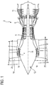
- the figure 1 is a simplified representation of an axial turbomachine. In this specific case, it is a double-flow turbojet engine.
- the turbojet engine 2 comprises a first level of compression, called the low-pressure compressor 4, a second level of compression, called the high-pressure compressor 6, a combustion chamber 8 and one or more levels of turbines 10.
- the mechanical power from the turbine 10 transmitted via the central shaft to the rotor 12 sets in motion the two compressors 4 and 6.
- the latter comprise several rows of rotor blades associated with rows of stator blades. The rotation of the rotor around its axis of rotation 14 thus makes it possible to generate an air flow and to compress it progressively until the inlet of the combustion chamber 8.
- a blower 16 is coupled to the rotor 12 and generates an air flow which is divided into a primary flow 18 passing through the various levels mentioned above of the turbomachine, and into a secondary flow 20 passing through a duct.
- the secondary flow can be accelerated so as to generate a thrust reaction.
- the primary 18 and secondary 20 flows are annular coaxial flows and fitted one inside the other.
- the blower can be of the non-vetted type, for example with double counter-rotating rotor, possibly downstream.
- the figure 2 is a sectional view of a compressor of an axial turbomachine such as that of the figure 1 .
- the compressor can be a low-pressure compressor 4.
- One can observe a part of the fan 16 and the separation nozzle 22 of the primary flow 18 and the secondary flow 20.
- the rotor 12 comprises several rows of rotor blades 24, in occurrence three.
- the low pressure compressor 4 comprises several rectifiers, in this case four, each containing a row of stator vanes 26.
- the rectifiers are associated with fan 16 or a row of rotor vanes to straighten the air flow, so as to convert the velocity of the flow into pressure.
- the stator vanes 26 extend essentially radially from an internal ferrule 28 to an external ferrule 30, or to an external casing.
- Said ferrules (28; 30) can carry annular layers of abradable material 32. These layers of abradable material 32 manage to crumble or wear out upon contact with the rotor 12 without damaging it. Thanks to this property, the abradable layer 32 can be brought closer to the rotor vanes 24 and the wipers, which improves the dynamic seal.
- the turbomachine is provided with a deicing system, or anti-icing system, associated with at least one or at least two abradable layers 32 upstream of the compressor 4.
- a deicing system or anti-icing system, associated with at least one or at least two abradable layers 32 upstream of the compressor 4.
- At least one or each ferrule (28; 30) is made in electrically insulating material, for example an organic matrix composite.
- the figure 3 sketch an assembly for ferrule (28; 30) according to the invention according to a first embodiment of the invention.
- the internal ferrule 28 has an annular partition 34 which supports an abradable layer 32.
- the internal ferrule 28 can be a ferrule at the inlet of the compressor, and can extend to the fan via an upstream overhang. Its upstream edge 33 can exceed the separation edge 23 of the separation spout 22.
- the annular profile of the annular partition 34 extends mainly axially.
- the partition 34 can be tubular, and substantially conical as an option. It shows an external surface 36 in contact with the primary flow 18 so as to delimit and guide it.
- the assembly includes a heating module 38 of the abradable layer 32 in order to reduce and prevent the formation, and / or accumulation, of ice on the internal ferrule 28. Efficiency is provided at the internal end of the blades stator 26.
- the heating module 38 is in thermal contact with the abradable layer 32. It is embedded therein. The external envelope of the latter also envelops the heating module 38.
- the abradable layer 32 and the optional partition 34 protect the heating module 38 from the primary flow 18, in particular from its abrasion.
- the abradable material can be silicone, for example molded directly on the partition 34 by encapsulating the heating module. Or, the abradable material can be projected by plasma into the internal ferrule 28. It can be a polymer matrix containing metallic grains, for example of the aluminum nickel, or aluminum silicon type.
- the heating module 38 comprises one or more electric heating resistors 42 in thermal contact with the abradable layer 32, and preferably embedded therein.
- Resistors 42 are electrical conductors. They produce heat by the Joule effect. It can be one or more electrical wires resistives placed at the heart of the abradable.
- the electric heating resistors can also be electrical tapes. These ribbons can form heating layers, which optionally describe coils or circles around the axis of rotation 14.
- heating resistors 42 can extend along the circumference, around the axis of rotation 14. They can form parallel and coaxial circles which are distributed axially along the ferrule 28. In the present example, four heating resistors 42 are represented, however any other number is possible.
- the electric heating elements 42 may each be single-stranded, and show a lower conductive section or equal to: 1mm 2, or 0.10 mm 2 or 0.02 mm 2. Reducing their cross-section increases the electrical resistance while reducing its mass.
- the heating resistors 42 are arranged along the internal ferrule 28. At least one or more heating resistors 42 are arranged axially at the stator vanes 26. At this location, the heat supply can be communicated to the vanes 26 by thermal conduction. . This tends to defrost them and to increase the heat exchange surface with the primary flow 18. Thus, the capacity of the system improves at the level of the external surface 36, and protects the boundary layers against frost.
- the rotor 12 of the compressor can show at least one or more wipers 44 cooperating by abrasion with the abradable layer 32.
- These wipers 44 form projecting annular ribs capable of digging grooves in the event of contact with the abradable 32.
- each wiper 44 is distant from the electric heating resistors 42, for example axially and / or radially. Radial distance can be designed to avoid grooves. Thus, the possible contact of the wipers 44 with the abradable 32 does not degrade the defrosting system.
- the heating modules are controlled by a control unit 46 of the defrosting system.
- the system can detect the presence of frost, measure a temperature, a humidity of the flow primary 18.
- the control unit 46 can be configured so as to heat the abradable layer 32 so that the temperature of the shell 28 remains above: 0 ° C, or 20 ° C, or 50 ° C.
- Electrical connections (not shown) can pass through the blades 26, and possibly a part of the separation nozzle 22, like an axial section of the compressor.
- the heating module comprises a source of magnetic field capable of heating the abradable layer, for example by generating an alternating current in the electric heating resistors.
- the magnetic field source can be accommodated in the separation spout.
- the present teaching can also be applied to the abradable layer 32 of the outer shell 30 of the separation spout 22, by housing a heating module as previously described therein.
- the figure 4 represents an assembly according to a second embodiment of the invention. This figure 4 uses the numbering of the previous figures for identical or similar elements, the number being however incremented by 100. Specific numbers are used for the elements specific to this embodiment.
- the figure 4 offers an enlargement at the internal ferrule 128.
- the second embodiment is substantially identical to the first embodiment, it is distinguished by the presence of pipes 148 in the heating module 138.
- These pipes 148 can be directly formed by the clean material of the abradable layer 132 , or by attached pipes.
- the pipes 148 can form a network in the thickness of the abradable layer 132, they scan the circumference and the axial length of the internal ferrule 128. They can form several tori internal to the ferrule. Their passage sections can vary from one torus to another.
- These pipes 148 can convey a heating fluid, for example a hot gas taken from the high pressure compressor, or a liquid such as lubricating oil for the turbomachine.
- a heating fluid for example a hot gas taken from the high pressure compressor, or a liquid such as lubricating oil for the turbomachine.
- the circulation of the fluid heats the ferrule 128 and opposes the presence of frost.
- the figure 5 represents an assembly according to a third embodiment of the invention. This figure 5 uses the numbering of the previous figures for identical or similar elements, the number being however incremented by 200. Specific numbers are used for the elements specific to this embodiment.
- the third embodiment is substantially identical to the first embodiment, it differs from it in that the abradable layer 232 is split, in particular radially. It comprises an outer annular layer 250, called the second layer; and an internal annular layer 252, called the first layer, fitted in the previous one.
- the outer layer 250 can receive the heating module 238, and in particular the electrical resistors 242. It can be a thermally conductive layer, which conducts heat more than the inner layer 252, for example at least twice, or at least ten times .
- the heating module 238 can essentially be enclosed in the outer layer 250.
- This configuration directs the heat exchange towards the bulkhead of the shell to better defrost it.
- the figure 6 represents an assembly according to a fourth embodiment of the invention. This figure 6 uses the numbering of the previous figures for identical or similar elements, the number being however incremented by 300.
- the fourth embodiment is substantially identical to the first embodiment, it differs from it in that the heating module 338 is disposed on the envelope of the abradable layer 332, the envelope can form the skin of the abradable.
- the heating module 338, and in particular of or each electric heating resistor 342 is disposed at the interface between the internal ferrule 328 and the layer of abradable material 332.
- the heating module 338 remains in the thickness of the abradable layer 332.
- Ferrule 328 has an essentially smooth interface surface 354 in contact with the abradable 332 and the module 338.
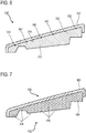
- the figure 7 shows an assembly according to a fifth embodiment of the invention. This figure 7 uses the numbering of the previous figures for identical or similar elements, the number being however incremented by 400. Specific numbers are used for the elements specific to this embodiment.
- the fifth embodiment is substantially identical to the first embodiment. However, it differs from it by the presence of particle 456 in the heating module 438.
- These particles 456 are electrically conductive. They are distributed in the abradable material 432. They can be distributed in an electrically insulating matrix. They can be in contact with each other, and supplied by connections. Then, the abradable material is electrically resistive and is configured to heat in order to oppose the presence of frost on the ferrule 428. Or, the particles 456 can be at a distance from each other and be heated by waves, like a electric field or a magnetic field.
- the same ferrule can combine the five embodiments of the invention.
- the heating modules can be distributed axially and / or radially in the mass of the same abradable layer.
Landscapes
- Engineering & Computer Science (AREA)
- Mechanical Engineering (AREA)
- General Engineering & Computer Science (AREA)
- Chemical & Material Sciences (AREA)
- Combustion & Propulsion (AREA)
- Structures Of Non-Positive Displacement Pumps (AREA)
Description
- L'invention se rapporte au domaine du dégivrage d'une turbomachine. Plus précisément, l'invention concerne un ensemble pour virole de turbomachine. L'invention a également trait à une turbomachine axiale, notamment un turboréacteur d'avion ou un turbopropulseur d'aéronef. L'invention propose en outre une utilisation d'une couche d'abradable.
- Le document
EP 2 418 387 A1 divulgue une virole de turboréacteur. La virole comprend: un support de forme généralement annulaire ou cylindrique avec une surface interne généralement circulaire; un anneau avec une surface interne et une surface externe opposée à ladite surface interne et disposée sur la surface interne dudit support; une couche de matériau abradable disposée sur la surface interne dudit anneau; remarquable en ce que ledit support est en matériau composite à matrice organique; et ledit anneau est en matériau métallique. Un tel arrangement permet de lier efficacement une couche abradable à un carter composite afin de garantir l'étanchéité. - Or dans un turboréacteur, une virole peut être sujette au phénomène de givrage. Lorsqu'un tel événement survient la glace peut se former au contact de la virole interne et de la virole externe tout en tapissant les surfaces intrados et extrados des aubes. A l'extrême, l'accumulation de givre parvient à boucher les passages entre les aubes, et donc à couper l'entrée d'air du compresseur qui ne peut plus alimenter la chambre de combustion. Le turboréacteur ne parvient plus à fournir de poussée.
- Le document
EP 3 023 511 A1 divulgue une composition pour joint abradable de compresseur de turbomachine. Le compresseur comprend des éléments chauffants aptes à réchauffer un revêtement de matériau abradable. Or aucune fonction n'est associée à ce chauffage. - L'invention a pour objectif de résoudre au moins un des problèmes posés par l'art antérieur. Plus précisément, l'invention a pour objectif d'optimiser le dégivrage d'une virole de turbomachine, et éventuellement d'un redresseur en entrée de compresseur. L'invention a également pour objectif de garantir le passage axial le long d'une virole de turbomachine. L'invention a également pour objectif de proposer une solution simple, résistante, légère, économique, fiable, facile à produire, commode d'entretien, d'inspection aisée, et améliorant le rendement.
- L'invention a pour objet un ensemble pour virole de turbomachine axiale à rotor, notamment une virole d'entrée de compresseur de turbomachine, l'ensemble comprenant une virole avec une couche annulaire de matériau abradable apte à coopérer par abrasion avec le rotor de la turbomachine, remarquable en ce qu'il comprend en outre un module de chauffage de la couche d'abradable afin de s'opposer à la présence de givre sur la virole.
- Selon des modes avantageux de l'invention, l'ensemble peut comprendre une ou plusieurs des caractéristiques suivantes, prises isolément ou selon toutes les combinaisons techniques possibles :
- Le module de chauffage comprend une résistance électrique chauffante en contact thermique de la couche d'abradable, préférentiellement, la résistance électrique présente une section inférieure ou égale à 1mm2, ou à 0,10mm2.
- La résistance électrique chauffante est disposée dans l'épaisseur radiale de la couche d'abradable.
- La résistance électrique chauffante comprend une ou plusieurs nappes électriques chauffantes.
- La couche d'abradable comprend une surface d'enveloppe, le module de chauffage étant en contact de ladite surface d'enveloppe.
- La surface d'enveloppe comprend une surface annulaire interne et/ou une surface annulaire externe, le module de chauffage étant en contact de la surface annulaire interne et/ou de la surface annulaire externe.
- Le matériau abradable est électriquement résistif et est configuré pour chauffer afin de s'opposer à la présence de givre sur la virole lorsque le module de dégivrage alimente électriquement ledit matériau de la couche abradable.
- La couche d'abradable comprend des particules électriquement conductrices et configurées pour chauffer la virole afin de s'opposer à la présence de givre sur la virole.
- La couche d'abradable forme un bloc de matière chauffant, notamment via une source d'énergie.
- La virole comprend en outre une cloison annulaire supportant la couche d'abradable au niveau d'une surface d'interface, le module de chauffage formant au moins partiellement ladite interface.
- Le module de chauffage comprend une source de champ magnétique apte à chauffer la couche d'abradable.
- La couche d'abradable comprend une première couche annulaire à distance radialement du module de chauffage et/ou une deuxième couche annulaire en contact du module de chauffage et qui présente une conductivité thermique supérieure à la conductivité thermique de la première couche.
- Le module de chauffage comprend un réseau chauffant en contact thermique de la couche d'abradable, ledit réseau étant éventuellement disposé dans l'épaisseur radiale de la couche d'abradable.
- Le réseau comprend une ou plusieurs canalisations pour fluide chauffant, notamment un gaz ou un liquide tel de l'huile.
- La virole est électriquement isolante et/ou électriquement isolée de la couche d'abradable.
- Le module de chauffage est adapté pour chauffer la couche d' abradable par ondes et/ou à l'aide d'un champ magnétique.
- La virole comprend une surface annulaire de guidage de flux annulaire de la turbomachine, ladite surface étant généralement tubulaire, et/ou entourant le module de chauffage.
- L'épaisseur radiale moyenne de la couche d'abradable est supérieure ou égale à : 2,00mm, ou à 5,00mm.
- La résistance électrique chauffante et/ou le réseau chauffant et/ou la ou plusieurs ou chaque canalisation de fluide chauffant forme(nt) au moins partiellement l'interface entre la couche d'abradable et la cloison annulaire de la virole ; et/ou est/sont disposés dans la couche thermiquement conductrice.
- Le matériau de la couche d'abradable est électriquement résistif de manière à le réchauffer lorsqu'il est alimenté électriquement afin de s'opposer à la présence de givre sur la virole.
- L'invention a également pour objet un ensemble pour joint de turbomachine axiale à rotor, notamment un joint d'entrée de compresseur de turbomachine, l'ensemble comprenant un joint avec une couche annulaire de matériau abradable apte à coopérer de manière étanche avec le rotor de la turbomachine, remarquable en ce qu'il comprend en outre un module de chauffage de la couche d'abradable afin de s'opposer à la présence de givre sur la virole.
- L'invention a également pour objet une turbomachine, notamment un turboréacteur, comprenant un ou au moins deux ensembles, remarquable en ce que le ou les au moins deux ensembles est/sont conforme(s) à l'invention, préférentiellement la turbomachine comprend un compresseur, la ou les au moins deux viroles d'ensemble étant des viroles dudit compresseur, le compresseur étant éventuellement un compresseur basse pression.
- Selon des modes avantageux de l'invention, l'ensemble peut comprendre une ou plusieurs des caractéristiques suivantes, prises isolément ou selon toutes les combinaisons techniques possibles :
La virole est une virole interne de redresseur amont du compresseur. - La turbomachine comprend un bec de séparation, éventuellement en entrée du compresseur, la virole étant une virole externe du bec de séparation.
- La turbomachine comprend une unité de commande configurée de sorte à chauffer la couche d'abradable de sorte que la température de la virole reste supérieure à 0°C.
- La turbomachine comprend une rangée annulaire d'aubes statoriques rigidement liées à la virole, le module de chauffage étant apte à chauffer la couche d'abradable de manière à s'opposer à la présence de givre sur les dites aubes statoriques, notamment au travers de la ou d'au moins une virole.
- Le rotor de la turbomachine comprend au moins une ou plusieurs léchettes coopérant par abrasion avec la couche d'abradable, la ou au moins une ou chaque léchette étant éventuellement à distance axialement et/ou radialement du module de chauffage de la couche d' abradable.
- La ou au moins une ou chaque léchette étant axialement à distance de la résistance électrique chauffante ; et/ou du réseau chauffant ; et/ou de la ou de plusieurs ou de chaque canalisation de fluide chauffant.
- Le compresseur comprend une pluralité de viroles internes dont une virole interne amont, la virole interne présentant un module de chauffage de la couche d'abradable afin de s'opposer à la présence de givre étant en aval de la virole amont.
- L'invention a également pour objet une utilisation d'une couche d' abradable chauffante pour dégivrer une virole de turbomachine axiale, la couche abradable comprenant éventuellement un matériau silicone ou une composition aluminium silicone polymère ou une composition aluminium nickel polymère, ladite couche d'abradable étant préférentiellement une couche d'abradable de virole associée à un module de chauffage de manière à former un ensemble conforme à l'invention.
- La couche d'abradable peut être intrinsèquement chauffante. Par intrinsèquement chauffante on peut entendre que la couche est apte à fournir des calories par elle-même. La couche d'abradable peut être un convertisseur d'énergie, par exemple convertissant une énergie électrique en une énergie thermique.
- De manière générale, les modes avantageux de chaque objet de l'invention sont également applicables aux autres objets de l'invention. Chaque objet de l'invention est combinable aux autres objets, et les objets de l'invention sont également combinables aux modes de réalisation de la description, qui en plus sont combinables entre eux, selon toutes les combinaisons techniques possibles.
- L'invention permet de couvrir efficacement les viroles tout en employant un système simple et compact puisqu'il se loge en partie dans les couches d'abradable. Cette solution est particulièrement bénéfique dans le contexte d'une virole interne en entrée de compresseur. Le dégivrage reste optimal même lorsque la virole interne s'étend en amont du bord de séparation du bec de séparation.
- L'énergie utilisée dans l'invention est facilement transportée et répartie dans la virole. La masse du système de dégivrage reste essentiellement réduite puisque les résistances électriques ou les canalisations restent minces, tout comme leur raccordement à l'unité de commande. L'invention ajoute un corps dans l'abradable qui en améliore la résistance sans en modifier la compacité.
- L'étendue de couverture peut être augmentée tout en restant homogène. Cette étendue peut être optimisée en fonction de l'importance du phénomène de givrage. Par conduction thermique via les aubes, l'effet antigivre se propage sur les surfaces intrados et extrados.
-
- La
figure 1 représente une turbomachine axiale selon l'invention. - La
figure 2 est un schéma d'un compresseur de turbomachine selon l'invention. - La
figure 3 illustre un ensemble pour virole selon un premier mode de réalisation de l'invention. - La
figure 4 illustre un ensemble pour virole selon un deuxième mode de réalisation de l'invention. - La
figure 5 illustre un ensemble pour virole selon un troisième mode de réalisation de l'invention. - La
figure 6 illustre un ensemble pour virole selon un quatrième mode de réalisation de l'invention. - La
figure 7 illustre un ensemble pour virole selon un cinquième mode de réalisation de l'invention. - Dans la description qui va suivre, les termes interne et externe renvoient à un positionnement par rapport à l'axe de rotation d'une turbomachine axiale. La direction axiale correspond à la direction le long de l'axe de rotation de la turbomachine. La direction radiale est perpendiculaire à l'axe de rotation. L'amont et l'aval sont en référence au sens d'écoulement principal du flux dans la turbomachine.
- La
figure 1 représente de manière simplifiée une turbomachine axiale. Il s'agit dans ce cas précis d'un turboréacteur double-flux. Le turboréacteur 2 comprend un premier niveau de compression, dit compresseur basse-pression 4, un deuxième niveau de compression, dit compresseur haute-pression 6, une chambre de combustion 8 et un ou plusieurs niveaux de turbines 10. En fonctionnement, la puissance mécanique de la turbine 10 transmise via l'arbre central jusqu'au rotor 12 met en mouvement les deux compresseurs 4 et 6. Ces derniers comportent plusieurs rangées d'aubes de rotor associées à des rangées d'aubes de stators. La rotation du rotor autour de son axe de rotation 14 permet ainsi de générer un débit d'air et de comprimer progressivement ce dernier jusqu'à l'entrée de la chambre de combustion 8. - Une soufflante 16 est couplée au rotor 12 et génère un flux d'air qui se divise en un flux primaire 18 traversant les différents niveaux sus mentionnés de la turbomachine, et en un flux secondaire 20 traversant un conduit. Le flux secondaire peut être accéléré de sorte à générer une réaction de poussée.
- Les flux primaire 18 et secondaire 20 sont des flux annulaires coaxiaux et emmanchés l'un dans l'autre. La soufflante peut être du type non carénée, par exemple à double rotor contrarotatifs, éventuellement en aval.
- La
figure 2 est une vue en coupe d'un compresseur d'une turbomachine axiale telle que celle de lafigure 1 . Le compresseur peut être un compresseur basse-pression 4. On peut y observer une partie de la soufflante 16 et le bec de séparation 22 du flux primaire 18 et du flux secondaire 20. Le rotor 12 comprend plusieurs rangées d'aubes rotoriques 24, en l'occurrence trois. - Le compresseur basse pression 4 comprend plusieurs redresseurs, en l'occurrence quatre, qui contiennent chacun une rangée d'aubes statoriques 26. Les redresseurs sont associés au fan 16 ou à une rangée d'aubes rotoriques pour redresser le flux d'air, de sorte à convertir la vitesse du flux en pression.
- Les aubes statoriques 26 s'étendent essentiellement radialement depuis une virole interne 28 jusqu'à une virole externe 30, ou à un carter externe. Lesdites viroles (28 ; 30) peuvent porter des couches annulaires de matériau abradable 32. Ces couches de matériau abradable 32 parviennent à s'effriter ou à s'user lors du contact avec le rotor 12 sans l'endommager. Grâce à cette propriété, les couche d'abradable 32 peuvent être rapprochées des aubes rotoriques 24 et des léchettes, ce qui permet d'améliorer l'étanchéité dynamique.
- Afin de s'opposer à la présence de givre, la turbomachine est munie d'un système de dégivrage, ou système antigivre, associé à au moins une ou à au moins deux couche d'abradable 32 en amont du compresseur 4. Au moins une ou chaque virole (28 ; 30) est réalisée en matériau isolant électriquement, par exemple en composite à matrice organique.
- La
figure 3 esquisse un ensemble pour virole (28 ; 30) selon l'invention selon un premier mode de réalisation de l'invention. - La virole interne 28 présente une cloison annulaire 34 qui supporte une couche d'abradable 32. La virole interne 28 peut être une virole en entrée du compresseur, et peut s'étendre jusqu'à la soufflante via un porte à faux amont. Son bord amont 33 peut dépasser le bord de séparation 23 du bec de séparation 22. Le profil annulaire de la cloison annulaire 34 s'étend principalement axialement. La cloison 34 peut être tubulaire, et sensiblement conique en option. Elle montre une surface externe 36 en contact du flux primaire 18 de sorte à le délimiter et à le guider.
- L'ensemble comprend un module de chauffage 38 de la couche d'abradable 32 afin de réduite et d'empêcher la formation, et/ou l'accumulation, de glace sur la virole interne 28. Une efficacité est apportée en extrémité interne des aubes statoriques 26. Le module de chauffage 38 est en contact thermique de la couche d'abradable 32. Il est noyé dedans. L'enveloppe externe de cette dernière enveloppe également le module de chauffage 38. La couche d'abradable 32 et l'optionnelle cloison 34 protègent le module de chauffage 38 du flux primaire 18, notamment de son abrasion.
- Le matériau abradable peut être du silicone, par exemple moulé à même la cloison 34 en encapsulant le module de chauffage. Ou encore, le matériau abradable peut être projeté par plasma dans la virole interne 28. Il peut s'agir d'une matrice polymère renfermant des grains métalliques, par exemple du type aluminium nickel, ou aluminium silicium.
- Le module de chauffage 38 comprend une ou plusieurs résistances électriques chauffantes 42 en contact thermique de la couche d'abradable 32, et préférentiellement noyées dedans. Les résistances 42 sont des conducteurs électriques. Elles produisent de la chaleur par effet joule. Il peut s'agir d'un ou de plusieurs fils électriques résistifs placés à cœur de l'abradable. Les résistances électriques chauffantes peuvent également être des rubans électriques. Ces rubans peuvent former des nappes chauffantes, qui décrivent éventuellement des serpentins ou des cercles autour de l'axe de rotation 14.
- Ces résistances chauffantes 42 peuvent s'étendre selon la circonférence, autour de l'axe de rotation 14. Ils peuvent former des cercles parallèles et coaxiaux qui sont répartis axialement le long de la virole 28. Dans le présent exemple, quatre résistances chauffantes 42 sont représentées, toutefois tout autre nombre est envisageable.
- Les résistances électriques chauffantes 42 peuvent chacune être monobrin, et montrer une section conductrice inférieure ou égale à : 1mm2, ou à 0,10mm2, ou à 0,02mm2. La réduction de leur section augmente la résistance électrique tout en en diminuant la masse.
- Les résistances chauffantes 42 sont disposées le long de la virole interne 28. Au moins une ou plusieurs résistances chauffantes 42 sont disposées axialement au niveau des aubes statoriques 26. A cet emplacement, l'apport de chaleur peut être communiqué aux aubes 26 par conduction thermique. Cela tend à les dégivrer et à augmenter la surface d'échange de chaleur avec le flux primaire 18. Ainsi, la capacité du système s'améliore au niveau radialement de la surface externe 36, et protège les couches limites contre le givre.
- Afin d'optimiser l'étanchéité, le rotor 12 du compresseur peut montrer au moins une ou plusieurs léchettes 44 coopérant par abrasion avec la couche d'abradable 32. Ces léchettes 44 forment des nervures annulaires saillantes aptes à creuser des sillons en cas de contact avec l'abradable 32. Optionnellement, chaque léchette 44 est éloignée des résistances électriques chauffantes 42, par exemple axialement et/ou radialement. L'éloignement radial peut être conçu pour éviter les sillons. Ainsi, l'éventuel contact des léchettes 44 avec l'abradable 32 ne dégrade pas le système de dégivrage.
- Le pilotage des modules de chauffage s'opère grâce à une unité de commande 46 du système de dégivrage. Le système peut détecter la présence de givre, mesurer une température, une humidité du flux primaire 18. L'unité de commande 46 peut être configurée de sorte à chauffer la couche d'abradable 32 de sorte que la température de la virole 28 reste supérieure à : 0°C, ou 20°C, ou 50°C. Des branchements électriques (non représentés) peuvent traverser les aubes 26, et éventuellement une partie du bec de séparation 22, comme un tronçon axial du compresseur.
- Suivant une option de l'invention, le module de chauffage comprend une source de champ magnétique apte à chauffer la couche d'abradable, par exemple en générant un courant alternatif dans les résistances électriques chauffantes. La source de champ magnétique peut être logée dans le bec de séparation.
- Le présent enseignement peut également s'appliquer à la couche d'abradable 32 de la virole externe 30 du bec de séparation 22, en y logeant un module de chauffage tel que précédemment décrit.
- La
figure 4 représente un ensemble selon un deuxième mode de réalisation de l'invention. Cettefigure 4 reprend la numérotation des figures précédentes pour les éléments identiques ou similaires, la numération étant toutefois incrémentée de 100. Des numéros spécifiques sont utilisés pour les éléments spécifiques à ce mode de réalisation. Lafigure 4 offre un agrandissement au niveau de la virole interne 128. - Le deuxième mode de réalisation est sensiblement identique au premier mode de réalisation, il s'en distingue par la présence de canalisations 148 dans le module de chauffage 138. Ces canalisations 148 peuvent être directement formées par le matériau propre de la couche d'abradable 132, ou par des tuyaux rapportés. Les canalisations 148 peuvent former un réseau dans l'épaisseur de la couche d'abradable 132, elles balayent la circonférence et la longueur axiale de la virole interne 128. Elles peuvent former plusieurs tores internes à la virole. Leurs sections de passage peuvent varier d'un tore à l'autre.
- Ces canalisations 148 peuvent véhiculer un fluide réchauffant, par exemple un gaz chaud prélevé dans le compresseur haute pression, ou un liquide tel de l'huile de lubrification de la turbomachine. La circulation du fluide réchauffe la virole 128 et s'oppose à la présence de givre.
- La
figure 5 représente un ensemble selon un troisième mode de réalisation de l'invention. Cettefigure 5 reprend la numérotation des figures précédentes pour les éléments identiques ou similaires, la numération étant toutefois incrémentée de 200. Des numéros spécifiques sont utilisés pour les éléments spécifiques à ce mode de réalisation. - Le troisième mode de réalisation est sensiblement identique au premier mode de réalisation, il en diffère toutefois en ce que la couche d'abradable 232 est scindée, notamment radialement. Elle comprend une couche annulaire externe 250, dite deuxième couche ; et une couche annulaire interne 252, dite première couche, emmanchée dans la précédente. La couche externe 250 peut recevoir le module de chauffage 238, et notamment les résistances électriques 242. Elle peut être une couche thermiquement conductrice, qui conduit davantage la chaleur que la couche interne 252, par exemple au moins deux fois, ou au moins dix fois. Le module de chauffage 238 peut essentiellement être renfermé dans la couche externe 250.
- Cette configuration oriente l'échange de chaleur vers la cloison de la virole pour mieux la dégivrer.
- La
figure 6 représente un ensemble selon un quatrième mode de réalisation de l'invention. Cettefigure 6 reprend la numérotation des figures précédentes pour les éléments identiques ou similaires, la numération étant toutefois incrémentée de 300. - Le quatrième mode de réalisation est sensiblement identique au premier mode de réalisation, il en diffère toutefois en ce que le module de chauffage 338 est disposé sur l'enveloppe de la couche d'abradable 332, l'enveloppe peut former la peau de l'abradable. Le module de chauffage 338, et notamment des ou chaque résistance électrique chauffante 342 est disposée à l'interface entre la virole interne 328 et la couche de matériau abradable 332. Le module de chauffage 338 reste dans l'épaisseur de la couche d'abradable 332. La virole 328 présente une surface d'interface 354 essentiellement lisse en contact de l'abradable 332 et du module 338.
- La
figure 7 représente un ensemble selon un cinquième mode de réalisation de l'invention. Cettefigure 7 reprend la numérotation des figures précédentes pour les éléments identiques ou similaires, la numération étant toutefois incrémentée de 400. Des numéros spécifiques sont utilisés pour les éléments spécifiques à ce mode de réalisation. - Le cinquième mode de réalisation est sensiblement identique au premier mode de réalisation. Cependant, il s'en démarque par la présence de particule 456 dans le module de chauffage 438. Ces particules 456 sont électriquement conductrices. Elles sont réparties dans le matériau abradable 432. Elles peuvent être réparties dans une matrice isolante électriquement. Elles peuvent être en contact les unes des autres, et alimentés par des branchements. Alors, le matériau abradable est électriquement résistif et est configuré pour chauffer afin de s'opposer à la présence de givre sur la virole 428. Ou encore, les particules 456 peuvent être à distance les unes des autres et être réchauffées par ondes, tel un champ électrique ou un champ magnétique.
- Selon l'invention, une même virole peut combiner les cinq modes de réalisation de l'invention. Les modules de chauffages peuvent être répartis axialement et/ou radialement dans la masse d'une même couche d'abradable.
Claims (15)
- Ensemble pour virole de turbomachine axiale (2) à rotor (12), notamment une virole d'entrée de compresseur (4) de turbomachine, l'ensemble comprenant une virole (28 ; 30 ; 128 ; 328 ; 428) avec une couche annulaire de matériau abradable (32; 132; 232; 332; 432) apte à coopérer par abrasion avec le rotor (12) de la turbomachine (2),
caractérisé en ce qu'il comprend en outre
un module de chauffage (38; 138; 238; 338; 438) de la couche d'abradable (32 ; 132 ; 232 ; 332 ; 432) afin de s'opposer à la présence de givre sur la virole (28 ; 30 ; 128 ; 328 ; 428). - Ensemble selon la revendication 1, caractérisé en ce que le module de chauffage (38 ; 238 ; 338) comprend une résistance électrique chauffante (42 ; 242 ; 342) en contact thermique de la couche d'abradable (32 ; 232 ; 332), préférentiellement, la résistance électrique (42 ; 242 ; 342) présente une section inférieure ou égale à 1mm2, ou à 0,10mm2., que la résistance électrique chauffante (42 ; 242 ; 342) étant éventuellement disposée dans l'épaisseur radiale de la couche d'abradable (32 ; 232 ; 332) et/ou comprenant éventuellement une ou plusieurs nappes électriques chauffantes.
- Ensemble selon l'une des revendications 1 ou 2, caractérisé en ce que la couche d'abradable (332) comprend une surface d'enveloppe, le module de chauffage (338) étant en contact physique de ladite surface d'enveloppe, la surface d'enveloppe comprenant éventuellement une surface annulaire interne (354) et/ou une surface annulaire externe, le module de chauffage (338) étant en contact physique de la surface annulaire interne (354) et/ou de la surface annulaire externe.
- Ensemble selon l'une des revendications 1 à 3, caractérisé en ce que la couche abradable (432) est électriquement résistive et est configurée pour chauffer afin de s'opposer à la présence de givre sur la virole (428) lorsque le module de dégivrage (438) alimente électriquement ledit matériau de la couche abradable (432).
- Ensemble selon l'une des revendications 1 à 4, caractérisé en ce que la couche d'abradable (432) comprend des particules électriquement conductrices et configurées pour chauffer la virole (428) afin de s'opposer à la présence de givre sur la virole (428).
- Ensemble selon l'une des revendications 1 à 5, caractérisé en ce que la virole (28) comprend en outre une cloison annulaire (34) supportant la couche d'abradable (32) au niveau d'une surface d'interface, le module de chauffage (38) formant au moins partiellement ladite interface.
- Ensemble selon l'une des revendications 1 à 6, caractérisé en ce que le module de chauffage (438) comprend une source de champ magnétique apte à chauffer la couche d'abradable (432).
- Ensemble selon l'une des revendications 1 à 7, caractérisé en ce que la couche d'abradable (232) comprend une première couche annulaire (252) à distance radialement du module de chauffage (238) et/ou une deuxième couche annulaire (250) en contact du module de chauffage (238) et qui présente une conductivité thermique supérieure à la conductivité thermique de la première couche (252).
- Ensemble selon l'une des revendications 1 à 8, caractérisé en ce que le module de chauffage comprend un réseau chauffant en contact thermique de la couche d'abradable (132), ledit réseau étant éventuellement disposé dans l'épaisseur radiale de la couche d'abradable (132), le réseau comprenant éventuellement une ou plusieurs canalisations (148) pour fluide chauffant, notamment un gaz ou un liquide tel de l'huile.
- Turbomachine (2), notamment un turboréacteur, comprenant un ou au moins deux ensembles, caractérisée en ce que le ou les au moins deux ensembles est/sont conforme(s) à l'une des revendications 1 à 9, préférentiellement la turbomachine (2) comprend un compresseur, la ou les au moins deux viroles (28; 30; 128; 328; 428) d'ensemble étant des viroles internes de redresseur amont dudit compresseur, le compresseur étant éventuellement un compresseur basse pression (4).
- Turbomachine (2) selon la revendication 10, caractérisée en ce qu'elle comprend un bec de séparation (22), éventuellement en entrée du compresseur, la virole étant une virole externe (30) du bec de séparation (22).
- Turbomachine (2) selon l'une des revendications 10 à 11, caractérisée en ce qu'elle comprend une unité de commande (46) configurée de sorte à chauffer la couche d'abradable (32) de sorte que la température de la virole (28 ; 30) reste supérieure à 0°C.
- Turbomachine (2) selon l'une des revendications 10 à 12, caractérisée en ce qu'elle comprend une rangée annulaire d'aubes statoriques (26) rigidement liées à la virole (28 ; 30), le module de chauffage (38) étant apte à chauffer la couche d'abradable (32) de manière à s'opposer à la présence de givre sur les dites aubes statoriques (26).
- Turbomachine (2) selon l'une des revendications 10 à 13, caractérisée en ce que le rotor (12) de la turbomachine (2) comprend au moins une ou plusieurs léchettes (44) coopérant par abrasion avec la couche d'abradable (32), la ou au moins une ou chaque léchette (44) étant éventuellement à distance axialement et/ou radialement du module de chauffage (38) de la couche d'abradable (32).
- Utilisation d'une couche d'abradable (32 ; 132 ; 232 ; 332 ; 432) chauffante pour dégivrer une virole (28 ; 30 ; 128 ; 328 ; 428) de turbomachine axiale, la couche abradable (32 ; 132 ; 232 ; 332 ; 432) comprenant éventuellement un matériau silicone ou une composition aluminium silicone polymère ou une composition aluminium nickel polymère, ladite couche d'abradable (32 ; 132 ; 232 ; 332 ; 432) étant préférentiellement une couche d'abradable de virole (28 ; 30 ; 128 ; 328 ; 428) associée à un module de chauffage (38 ; 138 ; 238 ; 338 ; 438) de manière à former un ensemble conforme à l'une des revendications 1 à 9.
Applications Claiming Priority (2)
| Application Number | Priority Date | Filing Date | Title |
|---|---|---|---|
| BE20165859A BE1024735B1 (fr) | 2016-11-15 | 2016-11-15 | Virole antigivre de compresseur de turbomachine axiale |
| PCT/EP2017/078208 WO2018091288A1 (fr) | 2016-11-15 | 2017-11-03 | Virole antigivre de compresseur de turbomachine axiale |
Publications (2)
| Publication Number | Publication Date |
|---|---|
| EP3542070A1 EP3542070A1 (fr) | 2019-09-25 |
| EP3542070B1 true EP3542070B1 (fr) | 2020-06-17 |
Family
ID=57394303
Family Applications (1)
| Application Number | Title | Priority Date | Filing Date |
|---|---|---|---|
| EP17801024.5A Active EP3542070B1 (fr) | 2016-11-15 | 2017-11-03 | Virole antigivre de compresseur de turbomachine axiale |
Country Status (4)
| Country | Link |
|---|---|
| US (1) | US11002150B2 (fr) |
| EP (1) | EP3542070B1 (fr) |
| BE (1) | BE1024735B1 (fr) |
| WO (1) | WO2018091288A1 (fr) |
Cited By (1)
| Publication number | Priority date | Publication date | Assignee | Title |
|---|---|---|---|---|
| FR3162787A1 (fr) * | 2024-05-28 | 2025-12-05 | Safran Aircraft Engines | Système de contrôle actif de jeux radiaux ou axiaux pour un joint abradable d’élément de turbomachine aéronautique |
Families Citing this family (4)
| Publication number | Priority date | Publication date | Assignee | Title |
|---|---|---|---|---|
| US10822999B2 (en) * | 2018-07-24 | 2020-11-03 | Raytheon Technologies Corporation | Systems and methods for fan blade de-icing |
| CN115030920B (zh) * | 2021-03-08 | 2026-01-23 | 中国航发商用航空发动机有限责任公司 | 航空发动机和飞机 |
| FR3166169A1 (fr) * | 2024-09-12 | 2026-03-13 | Safran Aircraft Engines | Pièce de turbomachine d’aéronef comportant un revêtement conducteur thermique améliorant la conductivité thermique d’un corps métallique |
| DE102024128180A1 (de) * | 2024-09-30 | 2026-04-02 | MTU Aero Engines AG | Elektrisches Anti-Vereisungssystem |
Family Cites Families (6)
| Publication number | Priority date | Publication date | Assignee | Title |
|---|---|---|---|---|
| US8257016B2 (en) * | 2008-01-23 | 2012-09-04 | Rolls-Royce Deutschland Ltd & Co Kg | Gas turbine with a compressor with self-healing abradable coating |
| FR2943717B1 (fr) * | 2009-03-27 | 2016-02-19 | Snecma | Stator de compresseur ou turbine de turbomachine permettant un controle du jeu en sommet d'aubes d'un rotor en regard |
| US9469408B1 (en) * | 2009-09-03 | 2016-10-18 | The Boeing Company | Ice protection system and method |
| EP2418387B1 (fr) | 2010-08-11 | 2015-04-01 | Techspace Aero S.A. | Virole externe de compresseur de turbomachine axiale |
| US9140187B2 (en) * | 2012-10-05 | 2015-09-22 | United Technologies Corporation | Magnetic de-icing |
| EP3023511B1 (fr) * | 2014-11-24 | 2021-07-28 | Safran Aero Boosters SA | Composition et joint abradable de carter de compresseur de turbomachine axiale |
-
2016
- 2016-11-15 BE BE20165859A patent/BE1024735B1/fr not_active IP Right Cessation
-
2017
- 2017-11-03 US US16/461,194 patent/US11002150B2/en active Active
- 2017-11-03 WO PCT/EP2017/078208 patent/WO2018091288A1/fr not_active Ceased
- 2017-11-03 EP EP17801024.5A patent/EP3542070B1/fr active Active
Non-Patent Citations (1)
| Title |
|---|
| None * |
Cited By (1)
| Publication number | Priority date | Publication date | Assignee | Title |
|---|---|---|---|---|
| FR3162787A1 (fr) * | 2024-05-28 | 2025-12-05 | Safran Aircraft Engines | Système de contrôle actif de jeux radiaux ou axiaux pour un joint abradable d’élément de turbomachine aéronautique |
Also Published As
| Publication number | Publication date |
|---|---|
| WO2018091288A1 (fr) | 2018-05-24 |
| BE1024735B1 (fr) | 2018-06-19 |
| US20190309653A1 (en) | 2019-10-10 |
| US11002150B2 (en) | 2021-05-11 |
| BE1024735A1 (fr) | 2018-06-11 |
| EP3542070A1 (fr) | 2019-09-25 |
Similar Documents
| Publication | Publication Date | Title |
|---|---|---|
| EP2075194B1 (fr) | Echangeur de chaleur air-huile pour turboréacteur, turboréacteur associé et utilisation dudit échangeur | |
| BE1024735B1 (fr) | Virole antigivre de compresseur de turbomachine axiale | |
| EP2821597B1 (fr) | Bec de séparation avec tôle formant une surface de guidage du flux et un canal de dégivrage | |
| EP3130765B1 (fr) | Bec de separation degivrant de compresseur de turbomachine axiale | |
| FR3027624A1 (fr) | Circuit de degivrage d'une levre d'entree d'air d'un ensemble propulsif d'aeronef | |
| FR2981686A1 (fr) | Turbomachine comprenant un recepteur a helices contrarotatives supporte par une enveloppe structurale fixee au carter intermediaire | |
| FR2943717A1 (fr) | Stator de compresseur ou turbine de turbomachine permettant un controle du jeu en sommet d'aubes d'un rotor en regard | |
| EP3023511A1 (fr) | Composition et joint abradable de carter de compresseur de turbomachine axiale | |
| EP3698050B1 (fr) | Carter extérieur de turbo-compresseur avec réservoir d'huile intégré | |
| FR2992347A1 (fr) | Recepteur de turbomachine d'aeronef a doublet d'helices contrarotatives non carenees, comprenant une turbine libre exterieure a maintien renforce | |
| FR3016956A1 (fr) | Echangeur de chaleur d'une turbomachine | |
| EP2766576B1 (fr) | Refroidissement de la queue d'aronde retenant une aube de turbomachine | |
| EP3153672B1 (fr) | Bec antigivre de compresseur basse pression de turbomachine axiale | |
| EP4127412A1 (fr) | Turbomachine d'aeronef equipee d'une machine electrique | |
| FR2999249A1 (fr) | Compresseur pour turbomachine dote de moyens de refroidissement d'un joint tournant assurant l'etancheite entre un redresseur et un rotor | |
| FR2955152A1 (fr) | Turbomachine a circulation de flux d'air de purge amelioree | |
| WO2020109705A1 (fr) | Turboréacteur à double flux comprenant un cône de sortie refroidi par son flux secondaire | |
| EP4129828A1 (fr) | Aéronef comprenant un dispositif d alimentation en hydrogène intégrant un système de chauffage de l hydrogène positionné dans le fuselage de l aéronef | |
| FR3039208A1 (fr) | Degivrage d’une levre d’entree d’air et refroidissement d’un carter de turbine d’un ensemble propulsif d’aeronef | |
| EP3870812B1 (fr) | Turbomachine d'aéronef equipée d'une machine électrique | |
| BE1024761B1 (fr) | Aube degivrante de compresseur de turbomachine axiale | |
| FR2996590A1 (fr) | Helice comportant un pivot pourvu d'une cellule a effet peltier | |
| FR3140137A1 (fr) | Turbomachine triple-flux avec échangeur de chaleur supportant une virole interne | |
| WO2024061737A1 (fr) | Turbomachine axiale triple-flux avec échangeur de chaleur | |
| EP4441341A1 (fr) | Bras de servitude pour un carter d'échappement d'une turbomachine |
Legal Events
| Date | Code | Title | Description |
|---|---|---|---|
| STAA | Information on the status of an ep patent application or granted ep patent |
Free format text: STATUS: UNKNOWN |
|
| STAA | Information on the status of an ep patent application or granted ep patent |
Free format text: STATUS: THE INTERNATIONAL PUBLICATION HAS BEEN MADE |
|
| PUAI | Public reference made under article 153(3) epc to a published international application that has entered the european phase |
Free format text: ORIGINAL CODE: 0009012 |
|
| STAA | Information on the status of an ep patent application or granted ep patent |
Free format text: STATUS: REQUEST FOR EXAMINATION WAS MADE |
|
| 17P | Request for examination filed |
Effective date: 20190506 |
|
| AK | Designated contracting states |
Kind code of ref document: A1 Designated state(s): AL AT BE BG CH CY CZ DE DK EE ES FI FR GB GR HR HU IE IS IT LI LT LU LV MC MK MT NL NO PL PT RO RS SE SI SK SM TR |
|
| AX | Request for extension of the european patent |
Extension state: BA ME |
|
| GRAP | Despatch of communication of intention to grant a patent |
Free format text: ORIGINAL CODE: EPIDOSNIGR1 |
|
| STAA | Information on the status of an ep patent application or granted ep patent |
Free format text: STATUS: GRANT OF PATENT IS INTENDED |
|
| DAV | Request for validation of the european patent (deleted) | ||
| DAX | Request for extension of the european patent (deleted) | ||
| INTG | Intention to grant announced |
Effective date: 20200218 |
|
| GRAS | Grant fee paid |
Free format text: ORIGINAL CODE: EPIDOSNIGR3 |
|
| GRAA | (expected) grant |
Free format text: ORIGINAL CODE: 0009210 |
|
| STAA | Information on the status of an ep patent application or granted ep patent |
Free format text: STATUS: THE PATENT HAS BEEN GRANTED |
|
| AK | Designated contracting states |
Kind code of ref document: B1 Designated state(s): AL AT BE BG CH CY CZ DE DK EE ES FI FR GB GR HR HU IE IS IT LI LT LU LV MC MK MT NL NO PL PT RO RS SE SI SK SM TR |
|
| REG | Reference to a national code |
Ref country code: GB Ref legal event code: FG4D Free format text: NOT ENGLISH |
|
| REG | Reference to a national code |
Ref country code: CH Ref legal event code: EP |
|
| REG | Reference to a national code |
Ref country code: IE Ref legal event code: FG4D Free format text: LANGUAGE OF EP DOCUMENT: FRENCH |
|
| REG | Reference to a national code |
Ref country code: DE Ref legal event code: R096 Ref document number: 602017018470 Country of ref document: DE |
|
| REG | Reference to a national code |
Ref country code: AT Ref legal event code: REF Ref document number: 1281641 Country of ref document: AT Kind code of ref document: T Effective date: 20200715 |
|
| PG25 | Lapsed in a contracting state [announced via postgrant information from national office to epo] |
Ref country code: LT Free format text: LAPSE BECAUSE OF FAILURE TO SUBMIT A TRANSLATION OF THE DESCRIPTION OR TO PAY THE FEE WITHIN THE PRESCRIBED TIME-LIMIT Effective date: 20200617 Ref country code: FI Free format text: LAPSE BECAUSE OF FAILURE TO SUBMIT A TRANSLATION OF THE DESCRIPTION OR TO PAY THE FEE WITHIN THE PRESCRIBED TIME-LIMIT Effective date: 20200617 Ref country code: GR Free format text: LAPSE BECAUSE OF FAILURE TO SUBMIT A TRANSLATION OF THE DESCRIPTION OR TO PAY THE FEE WITHIN THE PRESCRIBED TIME-LIMIT Effective date: 20200918 Ref country code: NO Free format text: LAPSE BECAUSE OF FAILURE TO SUBMIT A TRANSLATION OF THE DESCRIPTION OR TO PAY THE FEE WITHIN THE PRESCRIBED TIME-LIMIT Effective date: 20200917 Ref country code: SE Free format text: LAPSE BECAUSE OF FAILURE TO SUBMIT A TRANSLATION OF THE DESCRIPTION OR TO PAY THE FEE WITHIN THE PRESCRIBED TIME-LIMIT Effective date: 20200617 |
|
| REG | Reference to a national code |
Ref country code: LT Ref legal event code: MG4D |
|
| REG | Reference to a national code |
Ref country code: NL Ref legal event code: MP Effective date: 20200617 |
|
| PG25 | Lapsed in a contracting state [announced via postgrant information from national office to epo] |
Ref country code: HR Free format text: LAPSE BECAUSE OF FAILURE TO SUBMIT A TRANSLATION OF THE DESCRIPTION OR TO PAY THE FEE WITHIN THE PRESCRIBED TIME-LIMIT Effective date: 20200617 Ref country code: RS Free format text: LAPSE BECAUSE OF FAILURE TO SUBMIT A TRANSLATION OF THE DESCRIPTION OR TO PAY THE FEE WITHIN THE PRESCRIBED TIME-LIMIT Effective date: 20200617 Ref country code: LV Free format text: LAPSE BECAUSE OF FAILURE TO SUBMIT A TRANSLATION OF THE DESCRIPTION OR TO PAY THE FEE WITHIN THE PRESCRIBED TIME-LIMIT Effective date: 20200617 Ref country code: BG Free format text: LAPSE BECAUSE OF FAILURE TO SUBMIT A TRANSLATION OF THE DESCRIPTION OR TO PAY THE FEE WITHIN THE PRESCRIBED TIME-LIMIT Effective date: 20200917 |
|
| REG | Reference to a national code |
Ref country code: AT Ref legal event code: MK05 Ref document number: 1281641 Country of ref document: AT Kind code of ref document: T Effective date: 20200617 |
|
| PG25 | Lapsed in a contracting state [announced via postgrant information from national office to epo] |
Ref country code: NL Free format text: LAPSE BECAUSE OF FAILURE TO SUBMIT A TRANSLATION OF THE DESCRIPTION OR TO PAY THE FEE WITHIN THE PRESCRIBED TIME-LIMIT Effective date: 20200617 Ref country code: AL Free format text: LAPSE BECAUSE OF FAILURE TO SUBMIT A TRANSLATION OF THE DESCRIPTION OR TO PAY THE FEE WITHIN THE PRESCRIBED TIME-LIMIT Effective date: 20200617 |
|
| PG25 | Lapsed in a contracting state [announced via postgrant information from national office to epo] |
Ref country code: PT Free format text: LAPSE BECAUSE OF FAILURE TO SUBMIT A TRANSLATION OF THE DESCRIPTION OR TO PAY THE FEE WITHIN THE PRESCRIBED TIME-LIMIT Effective date: 20201019 Ref country code: IT Free format text: LAPSE BECAUSE OF FAILURE TO SUBMIT A TRANSLATION OF THE DESCRIPTION OR TO PAY THE FEE WITHIN THE PRESCRIBED TIME-LIMIT Effective date: 20200617 Ref country code: EE Free format text: LAPSE BECAUSE OF FAILURE TO SUBMIT A TRANSLATION OF THE DESCRIPTION OR TO PAY THE FEE WITHIN THE PRESCRIBED TIME-LIMIT Effective date: 20200617 Ref country code: SM Free format text: LAPSE BECAUSE OF FAILURE TO SUBMIT A TRANSLATION OF THE DESCRIPTION OR TO PAY THE FEE WITHIN THE PRESCRIBED TIME-LIMIT Effective date: 20200617 Ref country code: AT Free format text: LAPSE BECAUSE OF FAILURE TO SUBMIT A TRANSLATION OF THE DESCRIPTION OR TO PAY THE FEE WITHIN THE PRESCRIBED TIME-LIMIT Effective date: 20200617 Ref country code: RO Free format text: LAPSE BECAUSE OF FAILURE TO SUBMIT A TRANSLATION OF THE DESCRIPTION OR TO PAY THE FEE WITHIN THE PRESCRIBED TIME-LIMIT Effective date: 20200617 Ref country code: CZ Free format text: LAPSE BECAUSE OF FAILURE TO SUBMIT A TRANSLATION OF THE DESCRIPTION OR TO PAY THE FEE WITHIN THE PRESCRIBED TIME-LIMIT Effective date: 20200617 Ref country code: ES Free format text: LAPSE BECAUSE OF FAILURE TO SUBMIT A TRANSLATION OF THE DESCRIPTION OR TO PAY THE FEE WITHIN THE PRESCRIBED TIME-LIMIT Effective date: 20200617 |
|
| PG25 | Lapsed in a contracting state [announced via postgrant information from national office to epo] |
Ref country code: SK Free format text: LAPSE BECAUSE OF FAILURE TO SUBMIT A TRANSLATION OF THE DESCRIPTION OR TO PAY THE FEE WITHIN THE PRESCRIBED TIME-LIMIT Effective date: 20200617 Ref country code: PL Free format text: LAPSE BECAUSE OF FAILURE TO SUBMIT A TRANSLATION OF THE DESCRIPTION OR TO PAY THE FEE WITHIN THE PRESCRIBED TIME-LIMIT Effective date: 20200617 Ref country code: IS Free format text: LAPSE BECAUSE OF FAILURE TO SUBMIT A TRANSLATION OF THE DESCRIPTION OR TO PAY THE FEE WITHIN THE PRESCRIBED TIME-LIMIT Effective date: 20201017 |
|
| REG | Reference to a national code |
Ref country code: DE Ref legal event code: R097 Ref document number: 602017018470 Country of ref document: DE |
|
| PLBE | No opposition filed within time limit |
Free format text: ORIGINAL CODE: 0009261 |
|
| STAA | Information on the status of an ep patent application or granted ep patent |
Free format text: STATUS: NO OPPOSITION FILED WITHIN TIME LIMIT |
|
| PG25 | Lapsed in a contracting state [announced via postgrant information from national office to epo] |
Ref country code: DK Free format text: LAPSE BECAUSE OF FAILURE TO SUBMIT A TRANSLATION OF THE DESCRIPTION OR TO PAY THE FEE WITHIN THE PRESCRIBED TIME-LIMIT Effective date: 20200617 |
|
| 26N | No opposition filed |
Effective date: 20210318 |
|
| REG | Reference to a national code |
Ref country code: DE Ref legal event code: R119 Ref document number: 602017018470 Country of ref document: DE |
|
| PG25 | Lapsed in a contracting state [announced via postgrant information from national office to epo] |
Ref country code: MC Free format text: LAPSE BECAUSE OF FAILURE TO SUBMIT A TRANSLATION OF THE DESCRIPTION OR TO PAY THE FEE WITHIN THE PRESCRIBED TIME-LIMIT Effective date: 20200617 |
|
| REG | Reference to a national code |
Ref country code: CH Ref legal event code: PL |
|
| PG25 | Lapsed in a contracting state [announced via postgrant information from national office to epo] |
Ref country code: LU Free format text: LAPSE BECAUSE OF NON-PAYMENT OF DUE FEES Effective date: 20201103 |
|
| PG25 | Lapsed in a contracting state [announced via postgrant information from national office to epo] |
Ref country code: CH Free format text: LAPSE BECAUSE OF NON-PAYMENT OF DUE FEES Effective date: 20201130 Ref country code: LI Free format text: LAPSE BECAUSE OF NON-PAYMENT OF DUE FEES Effective date: 20201130 |
|
| PG25 | Lapsed in a contracting state [announced via postgrant information from national office to epo] |
Ref country code: IE Free format text: LAPSE BECAUSE OF NON-PAYMENT OF DUE FEES Effective date: 20201103 |
|
| PG25 | Lapsed in a contracting state [announced via postgrant information from national office to epo] |
Ref country code: DE Free format text: LAPSE BECAUSE OF NON-PAYMENT OF DUE FEES Effective date: 20210601 |
|
| PG25 | Lapsed in a contracting state [announced via postgrant information from national office to epo] |
Ref country code: TR Free format text: LAPSE BECAUSE OF FAILURE TO SUBMIT A TRANSLATION OF THE DESCRIPTION OR TO PAY THE FEE WITHIN THE PRESCRIBED TIME-LIMIT Effective date: 20200617 Ref country code: MT Free format text: LAPSE BECAUSE OF FAILURE TO SUBMIT A TRANSLATION OF THE DESCRIPTION OR TO PAY THE FEE WITHIN THE PRESCRIBED TIME-LIMIT Effective date: 20200617 Ref country code: CY Free format text: LAPSE BECAUSE OF FAILURE TO SUBMIT A TRANSLATION OF THE DESCRIPTION OR TO PAY THE FEE WITHIN THE PRESCRIBED TIME-LIMIT Effective date: 20200617 |
|
| PG25 | Lapsed in a contracting state [announced via postgrant information from national office to epo] |
Ref country code: MK Free format text: LAPSE BECAUSE OF FAILURE TO SUBMIT A TRANSLATION OF THE DESCRIPTION OR TO PAY THE FEE WITHIN THE PRESCRIBED TIME-LIMIT Effective date: 20200617 |
|
| PG25 | Lapsed in a contracting state [announced via postgrant information from national office to epo] |
Ref country code: SI Free format text: LAPSE BECAUSE OF FAILURE TO SUBMIT A TRANSLATION OF THE DESCRIPTION OR TO PAY THE FEE WITHIN THE PRESCRIBED TIME-LIMIT Effective date: 20200617 |
|
| PGFP | Annual fee paid to national office [announced via postgrant information from national office to epo] |
Ref country code: GB Payment date: 20251125 Year of fee payment: 9 |
|
| PGFP | Annual fee paid to national office [announced via postgrant information from national office to epo] |
Ref country code: FR Payment date: 20251125 Year of fee payment: 9 |
|
| PGFP | Annual fee paid to national office [announced via postgrant information from national office to epo] |
Ref country code: BE Payment date: 20251119 Year of fee payment: 9 |