EP3541450B1 - Self-regulating electrolytic gas generator and implant system comprising the same - Google Patents
Self-regulating electrolytic gas generator and implant system comprising the same Download PDFInfo
- Publication number
- EP3541450B1 EP3541450B1 EP17871751.8A EP17871751A EP3541450B1 EP 3541450 B1 EP3541450 B1 EP 3541450B1 EP 17871751 A EP17871751 A EP 17871751A EP 3541450 B1 EP3541450 B1 EP 3541450B1
- Authority
- EP
- European Patent Office
- Prior art keywords
- gas generator
- current collector
- electrolytic gas
- anode
- electrode
- Prior art date
- Legal status (The legal status is an assumption and is not a legal conclusion. Google has not performed a legal analysis and makes no representation as to the accuracy of the status listed.)
- Active
Links
Images





Classifications
-
- F—MECHANICAL ENGINEERING; LIGHTING; HEATING; WEAPONS; BLASTING
- F42—AMMUNITION; BLASTING
- F42B—EXPLOSIVE CHARGES, e.g. FOR BLASTING, FIREWORKS, AMMUNITION
- F42B3/00—Blasting cartridges, i.e. case and explosive
- F42B3/04—Blasting cartridges, i.e. case and explosive for producing gas under pressure
-
- A—HUMAN NECESSITIES
- A61—MEDICAL OR VETERINARY SCIENCE; HYGIENE
- A61M—DEVICES FOR INTRODUCING MEDIA INTO, OR ONTO, THE BODY; DEVICES FOR TRANSDUCING BODY MEDIA OR FOR TAKING MEDIA FROM THE BODY; DEVICES FOR PRODUCING OR ENDING SLEEP OR STUPOR
- A61M5/00—Devices for bringing media into the body in a subcutaneous, intra-vascular or intramuscular way; Accessories therefor, e.g. filling or cleaning devices, arm-rests
- A61M5/14—Infusion devices, e.g. infusing by gravity; Blood infusion; Accessories therefor
- A61M5/142—Pressure infusion, e.g. using pumps
- A61M5/14244—Pressure infusion, e.g. using pumps adapted to be carried by the patient, e.g. portable on the body
- A61M5/14276—Pressure infusion, e.g. using pumps adapted to be carried by the patient, e.g. portable on the body specially adapted for implantation
-
- A—HUMAN NECESSITIES
- A61—MEDICAL OR VETERINARY SCIENCE; HYGIENE
- A61F—FILTERS IMPLANTABLE INTO BLOOD VESSELS; PROSTHESES; DEVICES PROVIDING PATENCY TO, OR PREVENTING COLLAPSING OF, TUBULAR STRUCTURES OF THE BODY, e.g. STENTS; ORTHOPAEDIC, NURSING OR CONTRACEPTIVE DEVICES; FOMENTATION; TREATMENT OR PROTECTION OF EYES OR EARS; BANDAGES, DRESSINGS OR ABSORBENT PADS; FIRST-AID KITS
- A61F2/00—Filters implantable into blood vessels; Prostheses, i.e. artificial substitutes or replacements for parts of the body; Appliances for connecting them with the body; Devices providing patency to, or preventing collapsing of, tubular structures of the body, e.g. stents
- A61F2/02—Prostheses implantable into the body
- A61F2/022—Artificial gland structures using bioreactors
-
- A—HUMAN NECESSITIES
- A61—MEDICAL OR VETERINARY SCIENCE; HYGIENE
- A61K—PREPARATIONS FOR MEDICAL, DENTAL OR TOILETRY PURPOSES
- A61K48/00—Medicinal preparations containing genetic material which is inserted into cells of the living body to treat genetic diseases; Gene therapy
- A61K48/0075—Medicinal preparations containing genetic material which is inserted into cells of the living body to treat genetic diseases; Gene therapy characterised by an aspect of the delivery route, e.g. oral, subcutaneous
-
- A—HUMAN NECESSITIES
- A61—MEDICAL OR VETERINARY SCIENCE; HYGIENE
- A61M—DEVICES FOR INTRODUCING MEDIA INTO, OR ONTO, THE BODY; DEVICES FOR TRANSDUCING BODY MEDIA OR FOR TAKING MEDIA FROM THE BODY; DEVICES FOR PRODUCING OR ENDING SLEEP OR STUPOR
- A61M31/00—Devices for introducing or retaining media, e.g. remedies, in cavities of the body
- A61M31/002—Devices for releasing a drug at a continuous and controlled rate for a prolonged period of time
-
- A—HUMAN NECESSITIES
- A61—MEDICAL OR VETERINARY SCIENCE; HYGIENE
- A61M—DEVICES FOR INTRODUCING MEDIA INTO, OR ONTO, THE BODY; DEVICES FOR TRANSDUCING BODY MEDIA OR FOR TAKING MEDIA FROM THE BODY; DEVICES FOR PRODUCING OR ENDING SLEEP OR STUPOR
- A61M37/00—Other apparatus for introducing media into the body; Percutany, i.e. introducing medicines into the body by diffusion through the skin
- A61M37/0069—Devices for implanting pellets, e.g. markers or solid medicaments
-
- C—CHEMISTRY; METALLURGY
- C25—ELECTROLYTIC OR ELECTROPHORETIC PROCESSES; APPARATUS THEREFOR
- C25B—ELECTROLYTIC OR ELECTROPHORETIC PROCESSES FOR THE PRODUCTION OF COMPOUNDS OR NON-METALS; APPARATUS THEREFOR
- C25B1/00—Electrolytic production of inorganic compounds or non-metals
- C25B1/01—Products
- C25B1/02—Hydrogen or oxygen
- C25B1/04—Hydrogen or oxygen by electrolysis of water
-
- C—CHEMISTRY; METALLURGY
- C25—ELECTROLYTIC OR ELECTROPHORETIC PROCESSES; APPARATUS THEREFOR
- C25B—ELECTROLYTIC OR ELECTROPHORETIC PROCESSES FOR THE PRODUCTION OF COMPOUNDS OR NON-METALS; APPARATUS THEREFOR
- C25B9/00—Cells or assemblies of cells; Constructional parts of cells; Assemblies of constructional parts, e.g. electrode-diaphragm assemblies; Process-related cell features
- C25B9/17—Cells comprising dimensionally-stable non-movable electrodes; Assemblies of constructional parts thereof
- C25B9/19—Cells comprising dimensionally-stable non-movable electrodes; Assemblies of constructional parts thereof with diaphragms
- C25B9/23—Cells comprising dimensionally-stable non-movable electrodes; Assemblies of constructional parts thereof with diaphragms comprising ion-exchange membranes in or on which electrode material is embedded
-
- C—CHEMISTRY; METALLURGY
- C25—ELECTROLYTIC OR ELECTROPHORETIC PROCESSES; APPARATUS THEREFOR
- C25B—ELECTROLYTIC OR ELECTROPHORETIC PROCESSES FOR THE PRODUCTION OF COMPOUNDS OR NON-METALS; APPARATUS THEREFOR
- C25B9/00—Cells or assemblies of cells; Constructional parts of cells; Assemblies of constructional parts, e.g. electrode-diaphragm assemblies; Process-related cell features
- C25B9/60—Constructional parts of cells
- C25B9/65—Means for supplying current; Electrode connections; Electric inter-cell connections
-
- A—HUMAN NECESSITIES
- A61—MEDICAL OR VETERINARY SCIENCE; HYGIENE
- A61M—DEVICES FOR INTRODUCING MEDIA INTO, OR ONTO, THE BODY; DEVICES FOR TRANSDUCING BODY MEDIA OR FOR TAKING MEDIA FROM THE BODY; DEVICES FOR PRODUCING OR ENDING SLEEP OR STUPOR
- A61M5/00—Devices for bringing media into the body in a subcutaneous, intra-vascular or intramuscular way; Accessories therefor, e.g. filling or cleaning devices, arm-rests
- A61M2005/006—Devices for bringing media into the body in a subcutaneous, intra-vascular or intramuscular way; Accessories therefor, e.g. filling or cleaning devices, arm-rests for gases, e.g. CO2
-
- A—HUMAN NECESSITIES
- A61—MEDICAL OR VETERINARY SCIENCE; HYGIENE
- A61M—DEVICES FOR INTRODUCING MEDIA INTO, OR ONTO, THE BODY; DEVICES FOR TRANSDUCING BODY MEDIA OR FOR TAKING MEDIA FROM THE BODY; DEVICES FOR PRODUCING OR ENDING SLEEP OR STUPOR
- A61M5/00—Devices for bringing media into the body in a subcutaneous, intra-vascular or intramuscular way; Accessories therefor, e.g. filling or cleaning devices, arm-rests
- A61M5/14—Infusion devices, e.g. infusing by gravity; Blood infusion; Accessories therefor
- A61M5/142—Pressure infusion, e.g. using pumps
- A61M2005/14204—Pressure infusion, e.g. using pumps with gas-producing electrochemical cell
-
- A—HUMAN NECESSITIES
- A61—MEDICAL OR VETERINARY SCIENCE; HYGIENE
- A61M—DEVICES FOR INTRODUCING MEDIA INTO, OR ONTO, THE BODY; DEVICES FOR TRANSDUCING BODY MEDIA OR FOR TAKING MEDIA FROM THE BODY; DEVICES FOR PRODUCING OR ENDING SLEEP OR STUPOR
- A61M5/00—Devices for bringing media into the body in a subcutaneous, intra-vascular or intramuscular way; Accessories therefor, e.g. filling or cleaning devices, arm-rests
- A61M5/14—Infusion devices, e.g. infusing by gravity; Blood infusion; Accessories therefor
- A61M5/142—Pressure infusion, e.g. using pumps
- A61M5/14244—Pressure infusion, e.g. using pumps adapted to be carried by the patient, e.g. portable on the body
- A61M2005/14264—Pressure infusion, e.g. using pumps adapted to be carried by the patient, e.g. portable on the body with means for compensating influence from the environment
-
- A—HUMAN NECESSITIES
- A61—MEDICAL OR VETERINARY SCIENCE; HYGIENE
- A61M—DEVICES FOR INTRODUCING MEDIA INTO, OR ONTO, THE BODY; DEVICES FOR TRANSDUCING BODY MEDIA OR FOR TAKING MEDIA FROM THE BODY; DEVICES FOR PRODUCING OR ENDING SLEEP OR STUPOR
- A61M2202/00—Special media to be introduced, removed or treated
- A61M2202/02—Gases
- A61M2202/0208—Oxygen
-
- A—HUMAN NECESSITIES
- A61—MEDICAL OR VETERINARY SCIENCE; HYGIENE
- A61M—DEVICES FOR INTRODUCING MEDIA INTO, OR ONTO, THE BODY; DEVICES FOR TRANSDUCING BODY MEDIA OR FOR TAKING MEDIA FROM THE BODY; DEVICES FOR PRODUCING OR ENDING SLEEP OR STUPOR
- A61M2205/00—General characteristics of the apparatus
- A61M2205/75—General characteristics of the apparatus with filters
- A61M2205/7536—General characteristics of the apparatus with filters allowing gas passage, but preventing liquid passage, e.g. liquophobic, hydrophobic, water-repellent membranes
-
- A—HUMAN NECESSITIES
- A61—MEDICAL OR VETERINARY SCIENCE; HYGIENE
- A61M—DEVICES FOR INTRODUCING MEDIA INTO, OR ONTO, THE BODY; DEVICES FOR TRANSDUCING BODY MEDIA OR FOR TAKING MEDIA FROM THE BODY; DEVICES FOR PRODUCING OR ENDING SLEEP OR STUPOR
- A61M37/00—Other apparatus for introducing media into the body; Percutany, i.e. introducing medicines into the body by diffusion through the skin
-
- Y—GENERAL TAGGING OF NEW TECHNOLOGICAL DEVELOPMENTS; GENERAL TAGGING OF CROSS-SECTIONAL TECHNOLOGIES SPANNING OVER SEVERAL SECTIONS OF THE IPC; TECHNICAL SUBJECTS COVERED BY FORMER USPC CROSS-REFERENCE ART COLLECTIONS [XRACs] AND DIGESTS
- Y02—TECHNOLOGIES OR APPLICATIONS FOR MITIGATION OR ADAPTATION AGAINST CLIMATE CHANGE
- Y02E—REDUCTION OF GREENHOUSE GAS [GHG] EMISSIONS, RELATED TO ENERGY GENERATION, TRANSMISSION OR DISTRIBUTION
- Y02E60/00—Enabling technologies; Technologies with a potential or indirect contribution to GHG emissions mitigation
- Y02E60/30—Hydrogen technology
- Y02E60/36—Hydrogen production from non-carbon containing sources, e.g. by water electrolysis
Definitions
- the present invention relates generally to electrolytic gas generators and relates more particularly to a novel electrolytic gas generator and to an implant system comprising the same.
- Electrolysis is a common technique for generating such gases and typically involves converting a feedstock (which is often a low cost, stable reactant) to a useful commodity (which is often a high cost or unstable product) using an electrical current. Electrolysis is favored as a production technique due to its high process efficiency, its product selectivity, and its inherent ability to control production rate by controlling the applied current. Devices designed to generate one or more gases using electrolysis are sometimes referred to as electrolytic gas generators. Electrolytic gas generators for hydrogen production, for instance, are used frequently in analytical laboratories to supply high purity hydrogen, on-demand, for use as carrier and detector gases in gas chromatographs.
- Electrolytic gas generators for oxygen production have been used to generate oxygen in situ at skin wounds to improve the healing process for severe burns and diabetic ulcers.
- Such electrolytic gas generators typically require several basic system components to govern performance and safety, and these basic system components generally include current control (e.g., a DC power supply for maintaining generation rate and voltage efficiency), downstream pressure and gas purity monitoring (e.g., for process and environmental safety), and fluid management (e.g., water reactant feed pump and gas-liquid separation units).
- current control e.g., a DC power supply for maintaining generation rate and voltage efficiency
- downstream pressure and gas purity monitoring e.g., for process and environmental safety
- fluid management e.g., water reactant feed pump and gas-liquid separation units
- electrolytic gas generators can be used to produce other gases, such as, but not limited to, carbon dioxide, chlorine, ozone, hydrogen peroxide, chlorine dioxide, nitric oxide, sulfur dioxide, hydrogen sulfide, carbon monoxide, ammonia, hydrogen chloride, hydrogen bromide, and hydrogen cyanide.
- Subdermal implant devices are useful implements for the in situ generation and dissemination of therapeutics to a patient in need thereof for the treatment of various diseases, disorders, and/or conditions.
- implant devices comprise cells and/or tissues that are encapsulated within a suitable implantable container.
- the implantable container is typically designed to allow the cells and/or tissues to produce the desired therapeutic and for the dissemination of the produced therapeutic to the patient while, at the same time, limiting an immunological response.
- the delivery of essential gases (e.g., oxygen) and nutrients to implant devices is important for the viability and function of the cells and/or tissues contained therein.
- gases e.g., oxygen
- the cell containment subsystem is equipped with features to allow gas delivery through porous tubing or gas-only permeable internal gas compartments within the implantable cell containment subsystem.
- the gas generator subsystem includes components that allow access to water for electrolysis while implanted, thereby promoting long-term implantability of the gas generator subsystem.
- An application of the system is a pancreatic islet (or pancreatic islet analogue) implant for treatment of Type I diabetes (T1D) that would be considered a bioartificial pancreas.
- an implantable device comprising a chamber for holding functional cells and an oxygen generator for providing oxygen to the cells within the chamber.
- an oxygen generator i.e., an element that can produce oxygen and make it available to the functional cells, so that the functional cells do not suffer from hypoxia.
- the oxygen generator thus produces oxygen and typically releases the oxygen in the cell's vicinity.
- the oxygen generator comprises a pair of electrodes.
- the electrodes When an electric potential is applied across the electrodes, oxygen is released by electrolysis of ambient water molecules present within the chamber.
- the electrodes are connected to a power source, typically a rechargeable battery.
- the chamber may further comprise an oxygen sensor that determines the oxygen concentration in the vicinity of the functional cells.
- a microprocessor may be provided to turn on the oxygen generator when the sensor detects that the oxygen concentration is below a predetermined minimum and to turn it off when the oxygen concentration is above a predetermined maximum.
- the oxygen generator may be used to supply oxygen to cells contained by a culture plate, a culture flask, a microtiter plate or an extracorporeal circuit, or to cells in an encapsulating chamber for implanting in the body such as an immunoisolation chamber bounded by a semipermeable barrier layer that allows selected components to enter and leave the chamber.
- a bioactive molecule may be present with the cells.
- Oxygen can be delivered in situ to cells within the body such as by implanting the oxygen generator in proximity to cell-containing microcapsules in an intraperitoneal space, or by implanting a system containing the oxygen generator in proximity to an immunoisolation chamber containing cells.
- the oxygen generator may be connected to a current control circuit and a power supply.
- electrolytic gas generators of the type conventionally used with subdermal implant devices are configured to continuously generate a gas (which, in most cases, is oxygen) or are equipped with some external mechanism, such as a gas sensor and a current control device, to control actuation of the electrolytic gas generator.
- a gas which, in most cases, is oxygen
- some external mechanism such as a gas sensor and a current control device
- the continuous generation of gas may be undesirable for a subdermal implant device, especially if the rate of gas generation exceeds the rate at which the generated gas is consumed by cells and/or tissues of the implant device, as excess gas can lead to damage to the implant and/or the patient.
- external mechanisms for controlling gas generation can increase the size of the implant, which is undesirable, as well as adding to the cost and complexity of the implant.
- US 4,057,479 A discloses a solid polymer electrolyte cell that includes a solid polymer electrolyte membrane, an anode disposed on one side of and in contact with the membrane wherein the anode includes a substrate coated with lead dioxide and formed with one or more grooves therein, a cathode including a body of sintered nickel disposed on the other side of and in contact with the membrane, and a support structure corrugated on a surface portion thereof with such surface portion being in contact with the body of sintered nickel to maintain the body in contact with the membrane.
- water may be supplied to the grooves in the anode to ultimately cause a reaction at the interface of the membrane and the cathode to product hydrogen gas.
- US 3,933,526 A discloses a housing for a battery cell that includes a built-in switch for opening the circuit to the battery in response to excess pressure and/or temperature.
- the housing has a first conducting contact connected to the first battery electrode, and a second contact connected to the second electrode and connected through a wall of the housing to provide a circuit to the battery cell.
- the second contact may be a porous wall to allow gasses which form in the battery cell to pass to the outer housing wall, and when the pressure exceeds a predetermined value the outer wall will flex and open the electrical connection to the battery.
- the outer wall can be a bimetallic disc which flexes with rise in temperature of the battery cell to open the connection when the temperature exceeds a predetermined value.
- the pressure responsive action can be provided alone, the temperature responsive action can be provided alone, or the two features can be used in combination to provide a housing wherein the connection to the battery is opened in response to excessive pressure or temperature, or a combination of the two conditions.
- the disclosure in US 2009/042072 A1 generally relates to an on-demand hydrogen gas generation device, suitable for use in a fuel cell, which utilizes water electrolysis, and more particularly galvanic cell corrosion, and/or a chemical hydride reaction, to produce hydrogen gas.
- the disclosure additionally relates to such a device that comprises a switching mechanism that has an electrical current passing therethrough and that repeatedly and reversibly moves between a first position and a second position when exposed to pressure differential resulting from hydrogen gas generation, in order to (1) alter the rate at which hydrogen gas is generated, such that hydrogen gas is generated on an as-needed basis for a fuel cell connected thereto, and/or (2) ensure a substantially constant flow of hydrogen gas is released therefrom.
- the disclosure additionally or alternatively relates to such an on-demand hydrogen gas generation device that comprises a gas management system designed to maximize the release or evolution of hydrogen gas, and in particular dry hydrogen gas, therefrom once it has been formed, thus maximizing hydrogen gas output.
- the disclosure is still further directed to a fuel cell comprising such an on-demand hydrogen gas generation device, and in particular a fuel cell designed for small-scale application.
- US 2003/087427 A1 discloses an apparatus and method to enhance oxygen delivery to tissue encapsulated in an immunobarrier device.
- in situ electrochemical oxygen generation by electrolysis of water into oxygen and hydrogen supplies oxygen to the tissue.
- a thin, multilayer sheet electrolyzer is enclosed in silicone rubber membranes permeable to gas and water vapor but not liquids. The anode side of the electrolyzer is in contact with one face of the device. Water vapor diffuses into the electrolyzer, decomposes at the anode, and oxygen diffuses back through the membrane to the implanted tissue, thus providing a continuous supply of water, continuous diffusion of O2 and H2 out of the electrolyzer, and exclusion of biological components that might contaminate the electrolyzer.
- US 2015/0112247 A1 discloses a system for gas treatment of cellular implants.
- the system enhances the viability and function of cellular implants, particularly those with high cellular density, for use in human or veterinary medicine.
- the system utilizes a miniaturized electrochemical gas generator subsystem that continuously supplies oxygen and/or hydrogen to cells within an implantable and immunoisolated cell containment subsystem to facilitate cell viability and function at high cellular density while minimizing overall implant size.
- the cell containment subsystem is equipped with features to allow gas delivery through porous tubing or gas-only permeable internal gas compartments within the implantable cell containment subsystem.
- the gas generator subsystem includes components that allow access to water for electrolysis while implanted, thereby promoting long-term implantability of the gas generator subsystem.
- an electrolytic gas generator for electrolyzing a reactant to generate at least a first gas
- the electrolytic gas generator comprising (a) a polymer electrolyte membrane, the polymer electrolyte membrane having opposing first and second faces; (b) a first electrode, the first electrode being electrically coupled to the first face of the polymer electrolyte membrane; (c) a second electrode, the second electrode being electrically coupled to the second face of the polymer electrolyte membrane; (d) a first current collector, the first current collector being electrically-conductive and being reversibly deformable between a first state in which the first current collector is electrically coupled to the first electrode and a second state in which the first current collector is at least partially electrically disconnected from the first electrode; (e) a second current collector, the second current collector being electrically-conductive and being electrically coupled to the second electrode; and (f) a power source, the power source being electrically coupled to the first current collector and to the second current collector; (g) whereby,
- the electrolytic gas generator may be a water electrolyzer.
- the first current collector may be in direct physical and electrical contact with the first electrode in the first state and may be completely physically and electrically disconnected from the first electrode in the second state.
- the first current collector may be in direct physical and electrical contact with the first electrode in the first state and may be partially physically and electrically disconnected from the first electrode in the second state.
- the first electrode may be an anode
- the second electrode may be a cathode
- the electrolytic gas generator may further comprise a resiliently-compressible member engaged with the first current collector to bias the first current collector towards the first state.
- the resiliently-compressible member may comprise a block of foam.
- the foam may be an open-cell foam.
- the foam may be a closed-cell foam.
- the first current collector may be elastic.
- the first current collector may comprise a non-porous, gas-impermeable, electrically-conductive diaphragm.
- the first current collector may comprise a non-porous, gas-permeable, electrically-conductive diaphragm.
- the first current collector may comprise an electrically-conductive diaphragm and a ring terminal.
- the second current collector may comprise at least one pore.
- the electrolytic gas generator may further comprise a first fluid inlet for admitting outside fluid into the electrolytic gas generator to be electrolyzed.
- the electrolytic gas generator may further comprise a first fluid outlet for discharging from the electrolytic gas generator a first gas generated thereby.
- an electrolytic gas generator as defined in the independent claim 1 wherein the reactant is water, wherein the at least a first gas is oxygen gas and hydrogen gas, wherein the first current collector is reversible deformable when subjected to gas pressure
- the electrolytic gas generator comprising: a first seal, the first seal being disposed around a periphery of the first electrode, the first seal comprising a fluid outlet for discharging one of hydrogen and oxygen generated at the first electrode; a second seal, the second seal being disposed around a periphery of the second electrode, the second seal comprising a fluid outlet for discharging the other of hydrogen and oxygen generated at the second electrode; a first endplate, the first current collector being positioned between the first endplate and the polymer electrolyte membrane; a second endplate, the second current collector being positioned between the second endplate and the polymer electrolyte membrane; wherein at least one of the first seal, the second seal, the first endplate and the second endplate has
- the first current collector may be in direct physical and electrical contact with the first electrode in the first state and may be completely physically and electrically disconnected from the first electrode in the second state.
- the first current collector may be in direct physical and electrical contact with the first electrode in the first state and may be partially physically and electrically disconnected from the first electrode in the second state.
- the first electrode may be an anode
- the second electrode may be a cathode
- the electrolytic gas generator may further comprise a resiliently-compressible member positioned between and engaged with the first endplate and the first current collector to bias the first current collector towards the first state.
- the resiliently-compressible member may comprise a block of foam.
- the first current collector may comprise an elastic, non-porous, gas-impermeable, electrically-conductive diaphragm.
- the first current collector may comprise an elastic, non-porous, gas-permeable, electrically-conductive diaphragm
- the foam may be an open-cell foam
- the first endplate may comprise at least one pore.
- the electrolytic gas generator may further comprise an ultrafiltration membrane positioned within the at least one pore of the first endplate.
- the second current collector may comprise at least one pore
- the second endplate may comprise at least one pore
- the electrolytic gas generator may further comprise a liquid-permeable, gas-impermeable interface layer positioned between the second current collector and the second endplate.
- At least one of the first seal and the second seal has a fluid inlet for admitting outside water.
- an implant system comprising (a) at least one of the types of electrolytic gas generators described above; (b) a container for holding implantable one or more cells and/or tissues; and (c) a first tubing for conducting a gas generated by the electrolytic gas generator to the container.
- an implant system comprising (a) at least one of the types of electrolytic gas generators described above; (b) a container for holding implantable one or more cells and/or tissues; (c) a first tubing for conducting hydrogen generated by the electrolytic gas generator to the container; and (d) a second tubing for conducting oxygen generated by the electrolytic gas generator to the container.
- the present invention is directed, in part, at a novel electrolytic gas generator and is also directed, in part, at an implant system comprising said novel electrolytic gas generator.
- an important concept of the present invention is the design of an electrolytic gas generator that automatically undergoes one or more mechanical changes, such as a physical deformation of one or more components, during the course of electrolysis. More specifically, as current passes through the electrolytic gas generator of the present invention, products are generated at the anode and/or at the cathode, and electrolyte may also be transferred from one electrode to the other via electro-osmosis. In the case of water electrolysis, one or both of the gaseous products of hydrogen and oxygen that are generated by electrolysis may accumulate within the electrolytic gas generator if they do not exit the generator as quickly as they are generated.
- the accumulation of such gases within the electrolytic gas generator may result in an increased pressure in one or both electrode compartments, and this increase in pressure may, in turn, cause a mechanical change in certain components within the electrolytic gas generator.
- This electrolysis-induced mechanical change may then be taken advantage of to limit the extent of further electrolysis, as the mechanical change may be engineered to cause two electrically-conductive elements in the electrolytic gas generator that were in physical contact with one another to become partially or completely disconnected from one another.
- This disconnection may reduce or stop current flow, at which point the generated gas or gases may remain in their respective cell compartments until either they exit the electrolytic gas generator through their respective outlet ports and/or they diffuse through one or more permeable layers in the electrolytic gas generator to the surrounding environment.
- the electrolytic gas generator of the present invention may be capable of maintaining a constant gas activity in its vicinity so as to maintain cytoprotective, respiratory, and/or metabolic function of vicinal tissue or another implant and may do so with only a connection to an electrical source, such as a source of constant DC current.
- the constant DC current source such as a battery, may be co-implanted with the electrolytic gas generator or may be maintained outside the body and wired to the electrolytic gas generator percutaneously.
- Such a system could optionally be fitted with a secondary control system which, upon detection that the electrolytic gas generator has been de-actuated (i.e., by use of a current sensor), either slows the re-actuation process or prevents it entirely (i.e., latches the circuit open) to satisfy performance or safety criteria.
- a secondary control system which, upon detection that the electrolytic gas generator has been de-actuated (i.e., by use of a current sensor), either slows the re-actuation process or prevents it entirely (i.e., latches the circuit open) to satisfy performance or safety criteria.
- the electrolytic gas generator of the present invention is particularly amenable to a fully implanted medical device where oxygen is delivered by diffusion (i.e., via gas-permeable membranes) to cells or tissue in one or more implanted, immunoisolated capsules at rates governed by the metabolic consumption rate of said cells or tissue.
- oxygen pressure it is important to control oxygen pressure to accurately control dose, to mitigate the possible effects of hypoxia and hyperoxia, and to minimize power consumption and system complexity of a fully implanted system.
- the principles taught in the present application are equally applicable to an electrolytic gas generator wherein the gas generated under intrinsic pressure control is hydrogen at the cathode, or moreover, any anodically or cathodically produced electrolytic product gas.
- the intrinsic pressure management capability of the present invention is preferred or complementary in critical applications, such as implanted medical devices, to other pressure control methods, including but not limited to closed-loop process controller (pressure sensor plus current controller), external pressure switch, or pressure relief valve, due to the ability to control gas generation at its source (thereby precluding the risk of gas pressure buildup in the electrolytic gas generator in the case of a gas blockage in tubing intervening between said generator and these example extrinsic pressure management solutions).
- closed-loop process controller pressure sensor plus current controller
- external pressure switch external pressure switch
- pressure relief valve due to the ability to control gas generation at its source (thereby precluding the risk of gas pressure buildup in the electrolytic gas generator in the case of a gas blockage in tubing intervening between said generator and these example extrinsic pressure management solutions).
- elimination of a pressure sensor and process controller, or any additional electronic component comprises a simplification of an overall system which may result in smaller size, lower cost, and higher reliability.
- the use of pressure relief valves is generally precluded in implanted (or otherwise partially enclosed) applications, as there is not a readily convenient or safe location to shunt excess gas generated during valve actuation.
- the present invention affords an additional advantage over other methods of gas generation in implanted or otherwise partially contained applications, in that it may safely account for variations in ambient (i.e., barometric) pressure that would otherwise potentially put implant, subject, or host device at risk due to excessive pressure differential.
- the present invention is an improvement for implanted medical and many other applications, as it enables these simplifications without unduly compromising safety, reliability, size, cost or effectiveness.
- any application requiring in situ pressure-controlled generation of gas reagents in a small, intrinsically-safe, and/or reliable device may benefit from the teachings of this invention.
- Such alternative applications may include, for instance, corrosion inhibition or acceleration, odor control, cleansing and/or sanitization of surfaces or enclosed spaces, life support of immobilized or enclosed organisms, and reagent production for miniature sensors.
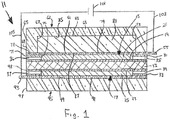
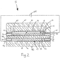
- FIGs. 1 and 2 there are shown schematic section views of a first embodiment of an electrolytic gas generator constructed according to the present invention, the electrolytic gas generator being represented generally by reference numeral 11.
- the electrolytic gas generator 11 being represented generally by reference numeral 11.
- certain components of electrolytic gas generator 11 that are not critical to an understanding of the present invention are either not shown or described herein or are shown and/or described herein in a simplified manner.
- Electrolytic gas generator 11 which may be in the form of a water electrolyzer, may comprise a solid polymer electrolyte membrane (PEM) 13 (also known in the art as a proton exchange membrane).
- PEM solid polymer electrolyte membrane
- Polymer electrolyte membrane 13 is preferably a non-porous, ionically-conductive, electrically-non-conductive, liquid-permeable and substantially gas-impermeable membrane.
- Polymer electrolyte membrane 13 may consist of or comprise a homogeneous perfluorosulfonic acid (PFSA) polymer. Said PFSA polymer may be formed by the copolymerization of tetrafluoroethylene and perfluorovinylether sulfonic acid. See e.g. , U.S. Patent No.
- a commercial embodiment of a PFSA polymer electrolyte membrane is manufactured by The Chemours Company FC, LLC (Fayetteville, NC) as NAFION TM extrusion cast PFSA polymer membrane.
- Polymer electrolyte membrane 13 may be a generally planar unitary structure in the form of a continuous film or sheet. In the present embodiment, when viewed from above or below, polymer electrolyte membrane 13 may have a generally circular shape. Moreover, the overall shape of electrolytic gas generator 11, when viewed from above or below, may correspond generally to the shape of polymer electrolyte membrane 13. However, it is to be understood that polymer electrolyte membrane 13, as well as electrolytic gas generator 11 as a whole, is not limited to a generally circular shape and may have a generally rectangular shape or other suitable shape.
- Electrolytic gas generator 11 may further comprise an anode 15 and a cathode 17.
- Anode 15 and cathode 17 may be positioned along two opposing major faces of polymer electrolyte membrane 13.
- anode 15 is shown positioned along the top face of polymer electrolyte membrane 13
- cathode 17 is shown positioned along the bottom face of polymer electrolyte membrane 13; however, it is to be understood that the positions of anode 15 and cathode 17 relative to polymer electrolyte membrane 13 could be reversed.
- Anode 15 may comprise an anode electrocatalyst layer 19 and an anode support 21.
- Anode electrocatalyst layer 19 may be positioned in direct contact with polymer electrolyte membrane 13 and, in the present embodiment, is shown as being positioned directly above and in contact with the top of polymer electrolyte membrane 13.
- Anode electrocatalyst layer 19 defines the electrochemically active area of anode 15 and preferably is sufficiently porous and electrically- and ionically-conductive to sustain a high rate of surface oxidation reaction.
- Anode electrocatalyst layer 19 which may be an anode electrocatalyst layer of the type conventionally used in a PEM-based water electrolyzer, may comprise electrocatalyst particles in the form of a finely divided electrically-conductive (and, optionally, ionically-conductive) material (e.g., a metal powder) which can sustain a high rate of electrochemical reaction.
- the electrocatalyst particles are distributed within anode electrocatalyst layer 19 along with a binder, which is preferably ionically-conductive, to provide mechanical fixation.
- Anode support 21 which may be an anode support of the type conventionally used in a PEM-based water electrolyzer and may be, for example, a film or sheet of porous titanium, preferably is sufficiently porous to allow fluid (gas and/or liquid) transfer between anode electrocatalyst layer 19 and the anode-side gas port to be discussed below.
- anode support 21 may have pore sizes on the order of, for example, approximately 0.001-0.5 mm.
- Anode support 21 may also contain macroscopic channel features, for example, on the order of 0.2-10 mm to further assist in fluid distribution.
- anode support 21 is electrically-conductive to provide electrical connectivity between anode electrocatalyst layer 19 and the anode-side current collector to be discussed below, and anode support 21 is also preferably ionically-non-conductive.
- Anode support 21 may be positioned in direct contact with anode electrocatalyst layer 19 and, in the present embodiment, is shown as being positioned directly on top of anode electrocatalyst layer 19 such that anode electrocatalyst layer 19 may be sandwiched between and in contact with polymer electrolyte membrane 13 and anode support 21.
- Anode support 21 may be dimensioned to entirely cover anode electrocatalyst layer 19, and, in fact, anode 15 may be fabricated by depositing anode electrocatalyst layer 19 on anode support 21.
- Cathode 17 may comprise a cathode electrocatalyst layer 23 and a cathode support 25.
- Cathode electrocatalyst layer 23 may be positioned in direct contact with polymer electrolyte membrane 13 and, in the present embodiment, is shown as being positioned directly below and in contact with polymer electrolyte membrane 13.
- Cathode electrocatalyst layer 23 defines the electrochemically active area of cathode 17 and preferably is sufficiently porous and electrically- and ionically-conductive to sustain a high rate of surface reduction reaction.
- Cathode electrocatalyst layer 23 which may be a cathode electrocatalyst layer of the type conventionally used in a PEM-based water electrolyzer, may comprise electrocatalyst particles in the form of a finely divided electrically-conductive (and, optionally, ionically-conductive) material (e.g., a metal powder) which can sustain a high rate of electrochemical reaction.
- the electrocatalyst particles are distributed within cathode electrocatalyst layer 23 along with a binder, which is preferably ionically-conductive, to provide mechanical fixation.
- an ionically-conductive medium comprising polymer electrolyte membrane 13 and optionally one or more ionically-conductive catalyst binders in electrocatalyst layers 19 and 23 couples the two electrodes and allows ions to flow in support of the overall reaction electrochemistry.
- Cathode support 25 which may be a cathode support of the type conventionally used in a PEM-based water electrolyzer and may be, for example, a film or sheet of porous carbon, preferably is sufficiently porous to allow fluid (gas and/or liquid) transfer between cathode electrocatalyst layer 23 and the cathode-side gas port to be discussed below.
- cathode support 25 may have pore sizes on the order of, for example, approximately 0.001-0.5 mm.
- Cathode support 25 may also contain macroscopic channel features, for example, on the order of 0.2-10 mm to further assist in fluid distribution.
- cathode support 25 is electrically-conductive to provide electrical connectivity between cathode electrocatalyst layer 23 and the cathode-side current collector to be discussed below, and cathode support 25 is also preferably ionically-non-conductive.
- Cathode support 25 may be positioned in direct contact with cathode electrocatalyst layer 23 and, in the present embodiment, is shown as being positioned directly below and in contact with cathode electrocatalyst layer 23 such that cathode electrocatalyst layer 23 may be sandwiched between and in contact with polymer electrolyte membrane 13 and cathode support 25.
- Cathode support 25 may be dimensioned to entirely cover cathode electrocatalyst layer 23, and, in fact, cathode 17 may be fabricated by depositing cathode electrocatalyst layer 23 on cathode support 25.
- the combination of polymer electrolyte membrane 13, anode 15, and cathode 17 or the combination of polymer electrolyte membrane 13, anode electrocatalyst layer 19, and cathode electrocatalyst layer 23 may be regarded collectively as a membrane-electrode assembly (MEA).
- MEA membrane-electrode assembly
- Electrolytic gas generator 11 may further comprise an anode seal 31 and a cathode seal 33.
- Anode seal 31 which may be an anode seal of the type conventionally used in a PEM-based water electrolyzer, may be a generally annular or frame-like member mounted around the periphery of anode 15 in a fluid-tight manner.
- Anode seal 31, which may be made of TEFLON TM polytetrafluoroethylene, ethylene-propylene-diene-monomer (EPDM) rubber, or another similarly suitable material, may be ionically-non-conductive and electrically-non-conductive.
- Anode seal 31 may also be non-porous and fluid-impermeable, except for a fluid port extending radially outwardly from the inner periphery of anode seal 31 to the outer periphery of anode seal 31.
- the aforementioned fluid port in anode seal 31 may be an oxygen outlet 35.
- Oxygen outlet 35 may be fluidically connected to a location in need of oxygen via suitable tubing (not shown), which tubing may be equipped with features like sterilization filters and/or check valves to prevent electrolytic gas generator 11 from becoming contaminated by contents of the tubing or from having condensate flow backwards into electrolytic gas generator 11.
- such tubing may be used to fluidically connect oxygen outlet 35 to a container holding implanted cells and/or tissue.
- such tubing may be eliminated if the container holding implanted cells and/or tissue is permeable to gas and the container is positioned against or sufficiently proximate to oxygen outlet 35.
- Anode seal 31 may additionally include a second fluid port extending radially outwardly from the inner periphery of anode seal 31 to the outer periphery of anode seal 31, which second fluid port may be used as a water inlet 36 to supply water to anode 15 from a source external to electrolytic gas generator 11.
- a water reservoir (not shown), which may be external to electrolytic gas generator 11, may be fluidically connected to water inlet 36 via suitable tubing (not shown) so as to supply water to anode 15.
- suitable tubing may be equipped with features like sterilization filters and/or check valves.
- electrolytic gas generator 11 is implanted in a body, such a water reservoir may also be implanted in the body, or the water reservoir may be positioned external to the body.
- ambient water in the local environment outside of electrolytic gas generator 11 may be supplied to electrolytic gas generator 11 through water inlet 36; however, in this case, it may be desirable to place one or more filters (not shown) over the exterior of water inlet 36 to keep select contaminants in the ambient water from entering water inlet 36 and to prevent anode-generated gas from exiting through water inlet 36.
- filters not shown
- Cathode seal 33 which may be a cathode seal of the type conventionally used in a PEM-based water electrolyzer, may be a generally annular or frame-like member mounted around the periphery of cathode 17 in a fluid-tight manner.
- Cathode seal 33 which may be made of TEFLON TM polytetrafluoroethylene, ethylene-propylene-diene-monomer (EPDM) rubber, or another similarly suitable material, may be ionically-non-conductive and electrically-non-conductive.
- Cathode seal 33 may also be non-porous and fluid-impermeable, except for two fluid ports extending radially outwardly from the inner periphery of cathode seal 33 to the outer periphery of cathode seal 33.
- one of the two fluid ports in cathode seal 33 may be a water inlet 37, which may be used to supply water to cathode 17 from a source external to electrolytic gas generator 11.
- a water reservoir (not shown), which may be external to electrolytic gas generator 11, may be fluidically connected to water inlet 37 via suitable tubing (not shown) so as to supply water to cathode 17.
- suitable tubing may be equipped with features like sterilization filters and/or check valves.
- electrolytic gas generator 11 is implanted in a body
- a water reservoir may also be implanted in the body, or the water reservoir may be positioned external to the body.
- ambient water in the local environment outside of electrolytic gas generator 11 may be supplied to electrolytic gas generator 11 through water inlet 37; however, in this case, it may be desirable to place one or more filters or flow control valves (not shown) over the exterior of water inlet 37 to keep select contaminants in the ambient water from entering water inlet 37 and to prevent cathode-generated gas from exiting through water inlet 37.
- the other of the two fluid ports in cathode seal 33 may be a hydrogen outlet 39.
- Hydrogen outlet 39 may be fluidically connected via suitable tubing (not shown) to a location in need of hydrogen or, if hydrogen is not needed, to a location where hydrogen may be safely expelled.
- suitable tubing may be equipped with features like sterilization filters and/or check valves.
- electrolytic gas generator 11 is implanted in a body and it is desired to treat implanted or native cells and/or tissue with hydrogen
- such tubing coupled to hydrogen outlet 39 may be used to deliver hydrogen to a container holding the implanted cells and/or tissue or may be used to deliver hydrogen to a location proximate to native cells and/or tissue.
- tubing can be used to deliver hydrogen to a part of the body where it can be safely expelled; alternatively, if electrolytic gas generator 11 is implanted at a location in a body where hydrogen can safely diffuse from electrolytic gas generator 11 and be expelled from the body without requiring any tubing, such tubing can be omitted.
- anode 15 and anode seal 31 may be dimensioned to jointly match the footprint of the top surface of polymer electrolyte membrane 13
- cathode 17 and cathode seal 33 may be dimensioned to jointly match the footprint of the bottom surface of polymer electrolyte membrane 13.
- Electrolytic gas generator 11 may further comprise an anode current collector 51.
- Anode current collector 51 which may be a unitary structure in the form of a continuous film or sheet, may be a non-porous, electrically-conductive, flexible, diaphragm-like member capable of being reversibly deformed (for example, when subjected to gas pressure) from a generally planar state to a bulging or distended state.
- anode current collector 51 may have a footprint that substantially matches the collective footprints of anode 15 and anode seal 31, except that anode current collector 51 may additionally comprise a tab 55 that may extend radially outwardly a short distance beyond the footprint of anode seal 31 and that may be used as a terminal.
- anode current collector 51 is preferably substantially gas-impermeable.
- anode current collector 51 is preferably elastic but need not be.
- materials that may be suitable for use as anode current collector 51 include, but are not limited to, silicones films or sheets with metallic (e.g., silver) or other electrically-conductive particles dispersed therein and non-porous, electrically-conductive, liquid-permeable, substantially gas-impermeable membranes of the type disclosed in U.S. Patent No. 9,595,727 B2, inventors Mittelsteadt et al., which issued March 14, 2017 .
- such a non-porous, electrically-conductive, liquid-permeable, substantially gas-impermeable membrane may comprise, for example, a solid polymer electrolyte into which electrically-conductive materials are dispersed.
- materials suitable for use as the solid polymer electrolyte may include (i) polymer compositions that contain metal salts; (ii) polymeric gels that contain electrolytes; and (iii) ion exchange resins.
- the solid polymer electrolyte may be, for example, a cation exchange ionomer membrane where the cation exchange group may be, but is not limited to, -SO 3 - , -SO 2 NH + , -PO 3 2- , or -CO 2 - or may be, for example, an anion exchange ionomer membrane where the anion exchange group may be, but is not limited to, -NH 2 + .
- a preferred material for use as the solid polymer electrolyte may be a perfluorosulfonic acid (PFSA) membrane, such as is manufactured by The Chemours Company FC, LLC (Fayetteville, NC) as NAFION TM extrusion cast PFSA polymer membrane. Examples of other materials that may be used in place of NAFION TM PFSA are disclosed in U.S. Patent No. 7,947,405 B2, inventors Mittelsteadt et al., which issued May 24, 2011 .
- Examples of materials that may be suitable for use as the dispersed, electrically-conductive materials of the above-described membrane may include high-aspect-ratio, electrically-conductive, non-particulate materials, such as carbon nanotubes, carbon nanofibers, metal nanowires, or combinations thereof.
- Carbon nanotubes that may be suitable for use in the membrane may have a diameter of about 0.20 nm to about 100 nm, may have a length of about 0.50 ⁇ m to about 200 ⁇ m, and may have an aspect ratio (i.e., length/diameter) in the range of about 5 to about 1,000,000.
- carbon nanotubes that may be suitable for use in the membrane may be non-functionalized or may include one or more functional groups, such as, but not limited to, -COOH, -PO 4 - , -SO 3 H, -SH, -NH 2 , tertiary amines, quaternary amines, -CHO, -OH, -NO 2 , and -PO 3 2- .
- carbon nanotubes that may be suitable for use in the membrane may include single-walled carbon nanotubes, double-walled carbon nanotubes, multi-walled carbon nanotubes, or combinations thereof.
- Carbon nanofibers that may be suitable for use in the membrane may be non-functionalized or may include one or more functional groups, such as, but not limited to, - COOH, -PO 4 - , -SO 3 H, -SH, -NH 2 , tertiary amines, quaternary amines, -CHO, -OH, -NO 2 , and -PO 3 2- .
- the membrane may comprise dispersed, electrically-conductive particles, such as, but not limited to, carbon black, metal particles (e.g., niobium particles, platinum particles, titanium particles, or combinations thereof), supported metal particles, or combinations thereof.
- the above-described membrane may be prepared by adding the electrically-conductive materials to the ionomer while the ionomer is in suspension form and then drying the suspension.
- Electrolytic gas generator 11 may further comprise an anode endplate 61.
- Anode endplate 61 which may be a unitary structure made of a rigid material of the type conventionally used in PEM-based water electrolyzers, such as a suitably strong metal or polymer, may have the shape of an inverted canister and may comprise a top wall 63 and a side wall 65 jointly defining an interior chamber 67 with an open bottom.
- Anode endplate 61 may be appropriately dimensioned so that an outer surface 69 of side wall 65 may be substantially aligned with an outer surface 71 of anode seal 31.
- anode endplate 61 may be further dimensioned so that an inner surface 73 of side wall 65 may be spaced radially outwardly relative to an inner surface 75 of anode seal 31.
- a vascularizing membrane (not shown), such as disclosed in U.S. Patent Application Publication No. US 2015/0112247 A1 , may be applied to one or more exposed surfaces of anode endplate 61.
- the bottom of side wall 65 of anode endplate 61 may be positioned directly on top of anode current collector 51 and may be used to secure a peripheral portion 77 of anode current collector 51 between anode endplate 61 and anode seal 31 (peripheral portion 77 of anode current collector 51 being positioned directly on top of anode seal 31).
- peripheral portion 77 of anode current collector 51 may be kept immobile between anode endplate 61 and anode seal 31 whereas a central portion 79 of anode current collector 51 may be free to flex upwardly away from anode 15 when a particular anodic gas pressure is reached between anode current collector 51 and anode 15, as will be discussed further below.
- electrolytic gas generator 11 stops electrolyzing.
- Electrolytic gas generator 11 may further comprise a resiliently-compressible member 81.
- Resiliently-compressible member 81 may be a structure designed to permit central portion 79 of anode current collector 51 to deform or to distend upwardly away from and out of contact with anode 15 when the gas pressure between anode current collector 51 and anode 15 exceeds a certain threshold gas pressure and to cause or to bias central portion 79 of anode current collector 51 to flatten or to deflate downwardly back into contact with anode 15 when the gas pressure between anode current collector 51 and anode 15 falls below a certain threshold gas pressure.
- the threshold gas pressure at which resiliently-compressible member 81 may permit central portion 79 to flex away from anode 15 and the threshold gas pressure at which resiliently-compressible member 81 may cause central portion 79 to flex back into contact with anode 15 may be the same or may be different. In some cases, it may be advantageous for the threshold gas pressure at which resiliently-compressible member 81 allows central portion 79 to flex away from anode 15 to be significantly greater than the threshold gas pressure at which resiliently-compressible member 81 forces central portion 79 to flex back into contact with anode 15. Consequently, in such a case, once the operation of electrolytic gas generator 11 has stopped, it will not resume until the gas pressure between central portion 79 and anode 15 has dropped significantly. In this manner, electrolytic gas generator 11 may be prevented from undesirably stuttering back and forth between its operating and off states.
- resiliently-compressible member 81 may comprise a block or disc of foam that may be disposed within interior chamber 67 of anode endplate 61.
- a foam may be a closed-cell foam or an open-cell foam.
- suitable foams may include, but are not limited to, polyurethane foams and silicone rubber foams, such as an open-cell silicone rubber foam.
- Resiliently-compressible member 81 may be appropriately dimensioned to have a first surface 83 engaged with an inner surface 85 of top wall 63 of anode endplate 61 and a second surface 87 engaged with anode current collector 51.
- resiliently-compressible member 81 may be dimensioned so that, when in its uncompressed state, it substantially fills the entire volume of interior chamber 67 of anode endplate 61; however, it is to be understood that resiliently-compressible member 81 need not be so dimensioned.
- resiliently-compressible member 81 may be a block of foam
- resiliently-compressible member 81 is not limited thereto and may be any type of resiliently-compressible structure, such as, but not limited to, a coil spring, a Belleville spring, an enclosed gas pocket, a gas pocket with an externally referenceable gas filling port, or combinations thereof.
- anode current collector 51 is sufficiently inherently resilient, it may be possible to omit resiliently-compressible member 81.
- Electrolytic gas generator 11 may further comprise a cathode current collector 91, which may be a cathode current collector of the type conventionally used in a PEM-based water electrolyzer and may be, for example, a platinum-coated titanium sheet.
- cathode current collector 91 may have a footprint that substantially matches the collective footprints of cathode 17 and cathode seal 33, except that cathode current collector 91 may additionally comprise a tab 93 that may extend radially outwardly a short distance beyond the footprint of cathode seal 33 and that may be used as a terminal.
- Electrolytic gas generator 11 may further comprise a cathode endplate 95, which may be a cathode endplate of the type conventionally used in a PEM-based water electrolyzer.
- Cathode endplate 95 may be appropriately dimensioned so that a side wall 97 thereof may be substantially aligned with an outer surface 98 of cathode seal 33.
- a top wall 99 of cathode endplate 95 may be positioned directly below cathode current collector 91 and may be used to keep cathode current collector 91 in direct contact with cathode 17 and with cathode seal 33.
- a vascularizing membrane (not shown), such as disclosed in U.S. Patent Application Publication No. US 2015/0112247 A1 , may be applied to one or more exposed surfaces of cathode endplate 95.
- Electrolytic gas generator 11 may further comprise a power source 101.
- Power source 101 which may be, for example, a DC battery (which may be rechargeable), may be electrically connected by a wire 103 to tab 55 of anode current collector 51 and by a wire 105 to tab 93 of cathode current collector 91.
- power source 101 may also be implanted in the patient; alternatively, power source 101 may be positioned external to the patient.
- Electrolytic gas generator 11 may further comprise other components commonly found in conventional PEM-based water electrolyzers.
- the static forces upon electrolytic gas generator 11 that may be required to compress resiliently-compressible member 81, to sustain good electrical contact of the serial components of electrolytic gas generator 11, and to achieve good sealing of the cell perimeter may be established and maintained using a variety of conventional fixturing or joining implements and techniques about the internal or external periphery of the assembly.
- Such implements may include, for instance, fasteners (e.g., screws, rivets, etc.) which may clamp the endplates 61 and 95 together, or adhesives, cements or welds which cohere the elements together in the seal region.
- fasteners e.g., screws, rivets, etc.
- Such implements and techniques are considered to be known to those of ordinary skill in the art.
- electrolytic gas generator 11 forms a closed electrical circuit, and electrolytic gas generator 11 is in an operating (or "on") state for the electrolysis of water.
- Water may be introduced into electrolytic gas generator 11 through water inlet 36 of anode seal 31 and/or water inlet 37 of cathode seal 33, and such water may be electrolyzed in the conventional manner at the electroactive interfaces of electrolytic gas generator 11, with oxygen gas being generated at the interface of polymer electrolyte membrane 13 and anode electrocatalyst layer 19 and with hydrogen gas being generated at the interface of polymer electrolyte membrane 13 and cathode electrocatalyst layer 23.
- the thus-generated oxygen gas may then exit electrolytic gas generator 11 through oxygen outlet 35, and the thus-generated hydrogen gas may then exit electrolytic gas generator 11 through hydrogen outlet 39.
- the rate at which oxygen gas may exit electrolytic gas generator 11 is greater than or approximately equal to the rate at which oxygen gas is generated by electrolytic gas generator 11, very little, if any, oxygen gas may build up between anode support 21 and anode current collector 51, and the upwardly-directed gas pressure exerted on anode current collector 51 may be less than the downwardly-directed mechanical pressure exerted on anode current collector 51 by resiliently-compressible member 81. As a result, electrical contact may be maintained between anode current collector 51 and anode support 21, and gas generation may continue.
- anode current collector 51 may flex or distend away from anode support 21, thereby breaking any electrical contact between anode current collector 51 and anode support 21.
- electrolytic gas generator 11 may stop electrolyzing water.
- At least some of the oxygen gas that has accumulated between anode support 21 and anode current collector 51 may exit electrolytic gas generator 11 through oxygen outlet 35 until the gas pressure between anode support 21 and anode current collector 51 decreases sufficiently for anode current collector 51 to be brought back into contact with anode support 21, thereby permitting electrolysis to resume.
- the foregoing scenario may take place in the context of a cell implant system in which the oxygen produced by electrolytic gas generator 11 is conducted by tubing to a closed container holding implanted cells and/or tissue. If the implanted cells and/or tissue cannot consume the oxygen that is delivered thereto at a rate that exceeds or is substantially equal to the rate at which the generated oxygen is delivered or if there is some restriction to flow downstream of oxygen outlet 35, oxygen may accumulate in the electrolytic gas generator 11 as described above. If the amount of oxygen that accumulates within electrolytic gas generator 11 is sufficient to create a pressure that exceeds a predetermined threshold, electrolytic gas generator 11 stops generating oxygen. In this manner, electrolytic gas generator 11 may be regarded as being self-regulating. As can be appreciated, such a self-regulating electrolytic gas generator is advantageous for at least the reason that it does not require external sensors or feedback mechanisms.
- FIGs. 3 and 4 there are shown schematic section views of a second embodiment of an electrolytic gas generator constructed according to the present invention, the electrolytic gas generator being represented generally by reference numeral 111.
- the electrolytic gas generator being represented generally by reference numeral 111.
- certain components of electrolytic gas generator 111 that are not critical to an understanding of the present invention are either not shown or described herein or are shown and/or described herein in a simplified manner.
- Electrolytic gas generator 111 which may be in the form of a water electrolyzer, may be similar in many respects to electrolytic gas generator 11. Accordingly, electrolytic gas generator 111 may comprise a polymer electrolyte membrane 113, which may be identical to polymer electrolyte membrane 13. In addition, electrolytic gas generator 111 may also comprise an anode 115 comprising an anode electrocatalyst layer 119 and an anode support 121, wherein anode 115, anode electrocatalyst layer 119, and anode support 121 may be identical to anode 15, anode electrocatalyst layer 19, and anode support 21, respectively, of electrolytic gas generator 11.
- electrolytic gas generator 111 may further comprise a cathode 117 comprising a cathode electrocatalyst layer 123 and a cathode support 125, wherein cathode 117, cathode electrocatalyst layer 123 and cathode support 125 may be identical to cathode 17, cathode electrocatalyst layer 23, and cathode support 25, respectively, of electrolytic gas generator 11.
- Electrolytic gas generator 111 may further comprise an anode seal 131 and a cathode seal 133.
- Anode seal 131 may be similar in most respects to anode seal 31, with a principal difference between the two anode seals being that, whereas anode seal 31 may comprise oxygen outlet 35 and water inlet 36, anode seal 131 may comprise an oxygen outlet 135 but need not include a water inlet. In fact, it may even be possible, in certain cases, for anode seal 131 not to include oxygen outlet 135.
- Cathode seal 133 may be similar in most respects to cathode seal 33, with a principal difference between the two cathode seals being that, whereas cathode seal 33 may comprise water inlet 37 and hydrogen outlet 39, cathode seal 133 may comprise a hydrogen outlet 139 but need not include a water inlet.
- Electrolytic gas generator 111 may further comprise an anode current collector 151.
- Anode current collector 151 may be similar in most respects to anode current collector 51, with a principal difference between the two anode current collectors being that, whereas anode current collector 51 may be substantially gas-impermeable, anode current collector 151 is gas-permeable.
- Anode current collector 151 is also preferably liquid-permeable.
- Electrolytic gas generator 111 may further comprise an anode endplate 161.
- Anode endplate 161 may be similar in most respects to anode endplate 61, with a principal difference between the two endplates being that, whereas anode endplate 61 may be made of a non-porous, fluid-impermeable material, anode endplate 161 may comprise a porous or fluid-permeable material.
- anode endplate 161 may comprise one or more pores 163. Pores 163 may permit the passage of gas or liquid from the external environment of anode endplate 161 to the internal chamber of anode endplate 161 or vice versa.
- pores 163 may allow pressure equalization with the local external pressure.
- outside water may be introduced into the anode side of electrolytic gas generator 111 through pores 163, and oxygen gas generated at anode 115 may be expelled from electrolytic gas generator 111 through pores 163.
- An ultrafiltration membrane 165 or other suitable membrane or filter may be positioned within pores 163 to keep select contaminants from passing from the exterior of electrolytic gas generator 111 through pores 163 into the interior chamber of anode endplate 161.
- ultrafiltration membrane 165 may be positioned across pores 163 along the exterior or interior surface of anode endplate 161.
- a vascularizing membrane (not shown), such as disclosed in U.S. Patent Application Publication No. US 2015/0112247 A1 , may be applied to one or more exposed surfaces of anode endplate 161.
- electrolytic gas generator 111 is implanted in a patient
- oxygen gas expelled through pores 163 may be delivered to a desired destination via one or more tubes coupled to pores 163.
- electrolytic gas generator 111 may be positioned near or at a desired destination, and expelled gas may simply diffuse to the desired destination without the use of tubing.
- a gas-permeable wall of a container holding implanted cells and/or tissue may be directly contacted with the exterior of anode endplate 161 so that oxygen expelled from pores 163 may pass directly into the container holding implanted cells and/or tissue.
- Electrolytic gas generator 111 may further comprise a resiliently-compressible member 181.
- Resiliently-compressible member 181 may be similar in most respects to resiliently-compressible member 81, with a principal difference between the two resiliently-compressible members being that, whereas resiliently-compressible member 81 need not be porous or gas-permeable, resiliently-compressible member 181 is preferably porous or gas-permeable to enable oxygen gas generated at anode 115 to pass therethrough. Therefore, for example, resiliently-compressible member 181 may be a suitable open-cell foam.
- Electrolytic gas generator 111 may further comprise a cathode current collector 191.
- Cathode current collector 191 may be similar in most respects to cathode current collector 91, with a principal difference between the two cathode current collectors being that, whereas cathode current collector 91 need not be porous, cathode current collector 191 may comprise one or more pores 192. As will become apparent below, pores 192 may be used to facilitate the passage of outside water to cathode 117.
- Electrolytic gas generator 111 may further comprise an interface layer 193.
- Interface layer 193, which is positioned below and in direct contact with cathode current collector 191, may comprise a liquid-permeable, gas-impermeable material.
- interface layer 193 may facilitate the passage of outside water therethrough to pores 192 of cathode current collector 191 while excluding contaminants (such as biomolecules in said outside water where, for example, electrolytic gas generator 111 is implanted in a patient) and may prevent gas generated at cathode 117 from egressing therethrough.
- a sealing gasket 194 may be positioned around the periphery of interface layer 193.
- Electrolytic gas generator 111 may further comprise a cathode endplate 195.
- Cathode endplate 195 may be similar in most respects to cathode endplate 95, with a principal difference between the two cathode endplates being that, whereas cathode endplate 95 need not be porous, cathode endplate 195 may comprise one or more pores 196, which may be used to communicate with the local environment and to facilitate the ingress of outside water into electrolytic gas generator 111 for delivery to cathode 117.
- electrolytic gas generator 111 is implanted in a patient, the outer surfaces of cathode endplate 195 and interface layer 193 may be treated to promote vascular ingrowth and tissue integration.
- a vascularizing membrane (not shown), such as disclosed in U.S. Patent Application Publication No. US 2015/0112247 A1 , may be applied to one or more exposed surfaces of cathode endplate 195.
- Electrolytic gas generator 111 may further comprise a power source 201, which may be identical to power source 101.
- Power source 201 may be electrically connected by a wire 203 to anode current collector 151 and by a wire 205 to cathode current collector 191.
- electrolytic gas generator 111 may further comprise other components commonly found in conventional PEM-based water electrolyzers.
- electrolytic gas generator 111 forms a closed electrical circuit, and electrolytic gas generator 111 is in an operating (or "on") state for the electrolysis of water.
- Water may be introduced into electrolytic gas generator 111 by passing first through pores 163 of anode endplate 161, then through resiliently-compressible member 181, and then through anode current collector 151.
- water may also be introduced into electrolytic gas generator 111 by passing through pores 196 of cathode endplate 195, then through interface layer 193, then through pores 192 of cathode current collector 191.
- Such water may then be electrolyzed in the conventional manner at the electroactive interfaces of electrolytic gas generator 111, with oxygen gas being generated at the interface of polymer electrolyte membrane 113 and anode electrocatalyst layer 119 and with hydrogen gas being generated at the interface of polymer electrolyte membrane 113 and cathode electrocatalyst layer 123.
- the thus-generated hydrogen gas may then exit electrolytic gas generator 111 through hydrogen outlet 139.
- a first portion may exit electrolytic gas generator 111 through oxygen outlet 135, a second portion may diffuse through anode current collector 151, then pass through resiliently-compressible material 181, and then pass through pores 163 of anode endplate 161, and a third portion may accumulate between anode current collector 151 and anode support 121. If the gas pressure of the third portion does not exceed the combination of the pressure applied by resiliently-compressive member 181 and the environmental pressure, anode current collector 151 may remain in contact with anode support 121, and electrolysis may continue.
- anode current collector 151 may be bent out of contact with anode support 121, as seen in Fig. 4 , thereby breaking any electrical contact between anode current collector 151 and anode support 121.
- electrolytic gas generator 111 may stop electrolyzing water.
- At least some of the oxygen gas that has accumulated between anode support 121 and anode current collector 151 may dissipate until the gas pressure between anode support 121 and anode current collector 151 decreases sufficiently for anode current collector 151 to be brought back into contact with anode support 121, thereby permitting electrolysis to resume.
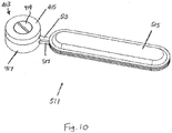
- FIG. 5 and 6 there are shown schematic section views of an alternate anode current collector constructed according to the present invention, the alternate anode current collector being represented generally by reference numeral 251.
- Anode current collector 251 which may be suitable for use in electrolytic gas generator 11, electrolytic gas generator 111, or other electrolytic gas generators operating on similar principles, may be similar in most respects to anode current collector 51 or to anode current collector 151 and may be used similarly to such anode current collectors.
- a principal difference between anode current collector 251 and anode current collector 51 or anode current collector 151 may be that, whereas anode current collector 51 or 151 may be a one-piece structure, anode current collector 251 may comprise the combination of an electrically-conductive diaphragm 253 and a ring terminal 255. Electrically-conductive diaphragm 253 may be similar in composition to anode current collector 51 or to anode current collector 151.
- Ring terminal 255 which may be an electrically-conductive member, may be bonded or otherwise fixed to electrically-conductive diaphragm 253.
- electrically-conductive diaphragm 253 when in its relaxed state, electrically-conductive diaphragm 253 lies substantially flat. Consequently, with electrically-conductive diaphragm 253 in such a flattened state, anode current collector 251 may be used to maintain an electrolytic gas generator in an operating (or "on" state).
- electrically-conductive diaphragm 253 may become distended, for example, when subjected to gas pressure and may extend though an opening 257 in ring terminal 255.
- anode current collector 251 may move out of electrical contact with its anode, thereby causing the respective electrolytic gas generator to be switched to a non-operating (or "off") state. Thereafter, when electrically-conductive diaphragm 253 is no longer subjected to such gas pressure or when the gas pressure decreases to a certain threshold, electrically-conductive diaphragm 253, due to a biasing force from resiliently-compressible member 81 or 181 and/or due to its own inherent resiliency, may once again assume a flattened state.
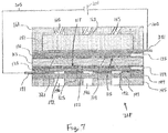
- FIGs. 7 and 8 there are shown schematic section views of a third embodiment of an electrolytic gas generator constructed according to the present invention, the electrolytic gas generator being represented generally by reference numeral 311.
- the electrolytic gas generator 311 is represented generally by reference numeral 311.
- certain components of electrolytic gas generator 311 that are not critical to an understanding of the present invention are either not shown or described herein or are shown and/or described herein in a simplified manner.
- Electrolytic gas generator 311 may be similar in most respects to electrolytic gas generator 111. A principal difference between the two electrolytic gas generators may be that, whereas electrolytic gas generator 111 may be configured so that anode current collector 151 makes no physical/electrical contact with anode support 121 when the gas pressure between anode current collector 151 and anode support 121 exceeds the combination of the pressure applied by resiliently-compressive member 181 and the environmental pressure, electrolytic gas generator 311 may comprise an anode support 321 and an anode current collector 351 that, under analogous pressure conditions, are configured to maintain some physical/electrical contact with one another, albeit to a diminished extent.
- Such a state which may be regarded as a "partially on” condition, results in reduced current through electrolytic gas generator 311, due to the added series resistance imposed by the longer and/or more tortuous conduction path. As a result of such a reduction in current, a reduction in gas production may ensue.
- an important feature of the present invention is the anode current collector, which sustains variable physical - and, therefore, variable electrical - contact with the anode support in response to differences in pressure on opposing faces of the anode current collector.
- a resiliently-compressible member e.g., rubber foam
- the essential components of the electrolytic gas generator may be improved by modification of the current collection scheme to enable a responsiveness to changes in either environmental pressure or the pressure of the generated gas.
- anode current collector to anode support to anode electrocatalyst layer to polymer electrolyte membrane to cathode electrocatalyst layer to cathode support and finally to cathode current collector.
- This state is considered “on” because the application of electrical power to the two collectors of the cell causes electrolytic gas generation.
- This gas generation ceases (the "off state) if any electrical or ionic pathway is opened (i.e., disconnected) and is reduced if any component in the series circuit develops a high resistance, as current is thereby attenuated (a "partially on” state).
- the "off state may be achieved by influence of the applied electrolytic current and the differential pressure between the gas electrolytically produced and the combination of environmental pressure communicated to the reference region within the anode endplate and the compression of the resiliently-compressible member.
- the dP value becomes negative, and the anode current collector deflects into the resiliently-compressible member and moves away from the anode support, causing mechanical separation and opening of the electrical circuit.
- the reestablishment of the "on" state may be part of the normal operation of the self-regulating electrolytic gas generator and is ensured by the judicious selection of the resiliently-compressible member such that the mechanical energy stored therein results in a force upon the active area of the electrolyzer sufficient to restore mechanical contact between the anode current collector and the anode support.
- the environmental pressure i.e., the barometric pressure or blood pressure of a subject having a cell implant utilizing the generated gas
- the environmental pressure changes, there will be a respective change in the displacement of the anode current collector so as to properly regulate the generation of gas and, thereby, adjust the pressure of the gas-treated implant.
- While the "on” - “off function may be suitable for general control of generated gas pressure, it may be preferable to regulate the current to a lower, non-zero value in order to achieve the finest pressure control.
- a “partially on” condition may be effected when the gas pressure P g and reference region pressure (sum of the resiliently-compressible member compression P c and environmental pressure P e ) have equalized and current continues to flow at a reduced rate proportional to the steady state rate of gas delivery to the application. Under constant power or voltage control of the electrolytic gas generator, current through the cell is reduced, in this case, by the added series resistance imposed by the longer and/or more tortuous conduction path. Referring to Fig.
- the mechanical properties of the resiliently-compressible member and the anode current collector, the contact and sheet resistivity properties of the anode current collector and the anode support, and the amount of compression of the resiliently-compressible member achieved should be taken into account.
- the endplate cavity depth and resiliently-compressible member thickness should be selected such that the compressed thickness of the resiliently-compressible member, when the endplate is fully compressed against the gaskets in the perimeter seal region, is storing the desired P c .
- This may be derived from the compressibility of the resiliently-compressible member, which is preferably selected from within the elastic deformation region of the material's stress-strain property in compression.
- electrolytic gas generator of the present invention has been described herein in certain embodiments as comprising, amongst other things, a reversibly distensible anode current collector and a resiliently-compressible member configured to bias the reversibly distensible anode current collector to a flattened state, it is to be understood that, in accordance with the present invention, one could modify such an electrolytic gas generator to instead have a reversibly distensible cathode current collector and a resiliently-compressible member configured to bias the reversibly distensible cathode current collector to a flattened state.
- an electrolytic gas generator may comprise, amongst other things, a reversibly distensible anode current collector, a resiliently-compressible member configured to bias the reversibly distensible anode current collector to a flattened state, a reversibly distensible cathode current collector, and a resiliently-compressible member configured to bias the reversibly distensible cathode current collector to a flattened state.
- the electrolytic gas generator of the present invention may be incorporated into a multi-cell stack, either made up exclusively of multiple units of the electrolytic gas generator of the present invention or in combination with conventional and/or novel electrolytic gas generators or other electrochemical cells.
- FIG. 9 there is shown a first embodiment of an implant system constructed according to the present invention, the implant system being represented generally by reference numeral 411. (For simplicity and clarity, certain components of implant system 411 that are not critical to an understanding of the present invention are either not shown or described herein or are shown and/or described herein in a simplified manner.)
- Implant system 411 may comprise an electrolytic gas generator 413.
- Electrolytic gas generator 413 may comprise any of the electrolytic gas generators described above encased within a housing top 415 and a housing bottom 417.
- Electrolytic gas generator 413 may further comprise a battery lid 419 under which the battery (not shown) for powering the electrolytic gas generator may be disposed.
- Implant system 411 may further comprise a container 421 for holding implanted cells and/or tissues.
- Container 421 may be, for example, a conventional container for holding implanted cells and/or tissues or may be, for example, a container of the type disclosed in U.S. Patent Application Publication No. US 2015/0112247 A1 .
- Implant system 411 may further comprise tubing 431 for fluidically connecting electrolytic gas generator 413 to container 421. More specifically, one end of tubing 431 may be fluidically coupled to the oxygen outlet of electrolytic gas generator 413 and the other end of tubing may be fluidically coupled to the interior of container 421. (Alternatively, tubing 431 could be used to fluidically couple the hydrogen outlet of electrolytic gas generator 413 to the interior of container 421.)
- FIG. 10 there is shown a second embodiment of an implant system constructed according to the present invention, the implant system being represented generally by reference numeral 511. (For simplicity and clarity, certain components of implant system 511 that are not critical to an understanding of the present invention are either not shown or described herein or are shown and/or described herein in a simplified manner.)
- Implant system 511 may be similar in most respects to implant system 411, a principal difference between the two implant systems being that, whereas implant system 411 may comprise tubing 431 for fluidically coupling either the oxygen outlet or the hydrogen outlet of electrolytic gas generator 413 to the interior of container 421, implant system 511 may comprise a first tubing 513 for fluidically coupling the oxygen outlet of electrolytic gas generator 413 to the interior of a container 515 and a second tubing 517 for fluidically coupling the hydrogen outlet of electrolytic gas generator 413 to the interior of container 515.
- Container 515 may be, for example, a container of the type disclosed in U.S. Patent Application Publication No. US 2015/0112247 A1 .
- Container 515 may optionally include a separate interface to the implanted tissue for diffusion of one or the other electrolytically generated gas away from the implant and into the body, instead of into the cells or tissues encapsulated in container 515.
- a pre-existing, small electrolysis cell was adapted for use as a self-regulating electrolytic gas generator.
- the cell used machined poly(etheretherketone) plastic endplates and stainless steel fasteners to maintain a constant mechanical load to the active and seal areas of the cell.
- the membrane-electrode assembly (MEA) at the heart of the cell utilized Solvay Aquivion ® E79-04SX perfluorosulfonic acid (PFSA) film as the proton-exchange membrane (PEM) and utilized platinum black catalysts (Engelhard, 4 mg/cm 2 ) for the electrocatalysts.
- PFSA Solvay Aquivion ® E79-04SX perfluorosulfonic acid
- PEM proton-exchange membrane
- platinum black catalysts Engelhard, 4 mg/cm 2
- the electrocatalysts were blended with Aquivion ® PFSA solution (Solvay Specialty Polymers) and applied to the PEM by decal transfer at 1000 psi and 175°C to unitize the MEA.
- the anode electrocatalyst contained iridium for improved voltage efficiency.
- the circular active catalyst area (2 cm 2 ) of the MEA was electrically contacted and mechanically reinforced on both sides with porous, conductive media comprising supports.
- the cathode support was porous carbon (Toray TGPH-090), and the anode support was porous titanium (ADMA Products).
- the border of the MEA was sealed with an adhesive-backed vinyl gasket.
- the cathode current collector was a platinum-coated titanium sheet with a tab for edge collection.
- the anode current collector (diaphragm collector) was a WaMM TM membrane (Giner, Inc., Newton, MA) comprising a carbon nanotube/PFSA blend fabricated per Example 8, Build 2, of U.S. Patent No. 9,595,727 B2 .
- the WaMM TM membrane was selected due to its high selective permeability of water vapor and good electrical conductivity, which are required for good cell performance.
- the WaMM TM membrane was cut to extend to the outer edge of the seal area and included a tab for current collection.
- the cylindrical volume defined by the anode face of the MEA, the inside wall of the anode side gasket, and the face of WaMM TM membrane contacting the anode support comprised the internal volume at high relative pressure.
- the WaMM TM membrane was supported on the face opposite the anode support by a 1/16" thick, resiliently-compressible, open-cell silicone rubber foam material (density - 12 lbs/ft3) cut to the same diameter as the active area.
- the seal area of the cell comprised a 1/16" thick square-profile, Buna-N rubber O-ring which resided peripherally about the foam.
- a small hole in the face of the anode side endplate allowed for communication of the region defined by the foam to the outside environment at low relative pressure.
- the rate of gas generation was thus decreasing at gas pressure maxima (approximately 20 psig in this case) and restored after a period of time sufficient for pressure to be relieved by mass transfer from the high relative pressure side of the diaphragm collector to the extent that the degree of electrical contact between the anode support and the diaphragm collector necessary for high current operation could be restored. Restoration of this current allowed renewed pressure differential at constant applied voltage, thereby causing another pressure-current-time cycle.
- a pre-existing, small electrolysis cell was adapted for use as a self-regulating electrolytic gas generator.
- the cell used machined poly(etheretherketone) plastic endplates and stainless steel fasteners to maintain a constant mechanical load to the active and seal areas of the cell. Registration pin holes were added to maintain alignment of the gaskets and oxygen port.
- the membrane-electrode assembly (MEA) at the heart of the cell utilized Solvay Aquivion ® E79-05S perfluorosulfonic acid (PFSA) film as the proton-exchange membrane (PEM) and utilized platinum black catalysts (Engelhard, 4 mg/cm 2 ) for the electrocatalysts.
- PFSA perfluorosulfonic acid
- EEM proton-exchange membrane
- Engelhard platinum black catalysts
- the electrocatalysts were blended with Aquivion ® PFSA solution (Solvay Specialty Polymers) and applied to the PEM by decal transfer at 1000 psi and 175°C to unitize the MEA.
- the anode electrocatalyst contained iridium for improved voltage efficiency.
- the circular active catalyst area (1 cm 2 ) of the MEA was electrically contacted and mechanically reinforced on both sides with porous, conductive media comprising supports.
- the cathode support was porous carbon (Toray TGPH-090), and the anode support was porous titanium (ADMA Products).
- the border of the MEA was sealed with polytetrafluoroethylene gaskets on the periphery of both anode and cathode faces.
- the cathode current collector was a platinum-coated titanium sheet with a tab for edge collection.
- the anode current collector was a platinum-coated titanium annulus with a tab for edge collection.
- Between the MEA and the anode current collector were a non-conductive annulus with a port for gas collection (contacting the MEA) and a conductive diaphragm made of Cho-Seal 1215 elastomer (a conductive material made of silver-plated copper filler in a silicone binder, a product of Parker Chomerics, Woburn, MA) which lay between the non-conductive annulus and the anode current collector.
- the Cho-Seal 1215 was selected due to its good electrical conductivity and elastic mechanical properties.
- the cylindrical volume defined by the anode face of the MEA, the inside walls of the anode side gasket and non-conductive port, and the face of the conductive diaphragm contacting the anode support comprised the internal volume at high relative pressure.
- the conductive diaphragm was supported on the face opposite the anode support by a 1/8" thick, open-cell polyurethane polyether foam material (Formulation 1034 fabricated by New England Foam Products, LLC, Hartford, CT; density - 0.9 lb/ft 3 ) cut to a diameter slightly larger than the active area diameter.
- the seal area of the cell comprised a 0.07" thick, square-profile, polytetrafluoroethylene gasket which resided peripherally about the foam.
- a small hole in the center of the anode side endplate face allowed for communication of the region defined by the foam to the outside environment at low relative pressure.
- a second hole through the face of the anode side endplate allowed for gas generated at the MEA and collected through the non-conductive port to be routed out of the cell.
- the electrolytic gas generator so described was fitted to a test system having a DC power supply to provide current to the cell, a flowmeter (Alicat Scientific M-0.5SCCM-D) and a pressure transducer (IFM PX3238) on the oxygen outlet, and flow restricting valve venting to the atmosphere.
- a DC power supply to provide current to the cell
- a flowmeter Alicat Scientific M-0.5SCCM-D
- IFM PX3238 pressure transducer
- the cell was observed to begin oscillating in current indefinitely between about 2 mA to about 10 mA at approximately 10 second intervals.
- the rate of gas generation oxygen gas flow rate in standard cubic centimeters per hour, scch
Landscapes
- Health & Medical Sciences (AREA)
- Engineering & Computer Science (AREA)
- Chemical & Material Sciences (AREA)
- Life Sciences & Earth Sciences (AREA)
- Animal Behavior & Ethology (AREA)
- Veterinary Medicine (AREA)
- Public Health (AREA)
- General Health & Medical Sciences (AREA)
- Heart & Thoracic Surgery (AREA)
- Biomedical Technology (AREA)
- Anesthesiology (AREA)
- Hematology (AREA)
- Medicinal Chemistry (AREA)
- Vascular Medicine (AREA)
- Metallurgy (AREA)
- Chemical Kinetics & Catalysis (AREA)
- Organic Chemistry (AREA)
- Materials Engineering (AREA)
- Electrochemistry (AREA)
- Bioinformatics & Cheminformatics (AREA)
- Genetics & Genomics (AREA)
- Molecular Biology (AREA)
- Biotechnology (AREA)
- Pharmacology & Pharmacy (AREA)
- Epidemiology (AREA)
- General Engineering & Computer Science (AREA)
- Transplantation (AREA)
- Dermatology (AREA)
- Medical Informatics (AREA)
- Cardiology (AREA)
- Oral & Maxillofacial Surgery (AREA)
- Inorganic Chemistry (AREA)
- Electrolytic Production Of Non-Metals, Compounds, Apparatuses Therefor (AREA)
- Infusion, Injection, And Reservoir Apparatuses (AREA)
- Electrodes For Compound Or Non-Metal Manufacture (AREA)
Description
- This invention was made with government support under Grant Number 1R43DK113536-01, awarded by NIH-NIDDK. The government has certain rights in the invention.
- The present invention relates generally to electrolytic gas generators and relates more particularly to a novel electrolytic gas generator and to an implant system comprising the same.
- The controlled generation of one or more types of gases at point-of-use is of significance to a multitude of industrial and medical applications. Electrolysis is a common technique for generating such gases and typically involves converting a feedstock (which is often a low cost, stable reactant) to a useful commodity (which is often a high cost or unstable product) using an electrical current. Electrolysis is favored as a production technique due to its high process efficiency, its product selectivity, and its inherent ability to control production rate by controlling the applied current. Devices designed to generate one or more gases using electrolysis are sometimes referred to as electrolytic gas generators. Electrolytic gas generators for hydrogen production, for instance, are used frequently in analytical laboratories to supply high purity hydrogen, on-demand, for use as carrier and detector gases in gas chromatographs. Electrolytic gas generators for oxygen production, for example, have been used to generate oxygen in situ at skin wounds to improve the healing process for severe burns and diabetic ulcers. Such electrolytic gas generators typically require several basic system components to govern performance and safety, and these basic system components generally include current control (e.g., a DC power supply for maintaining generation rate and voltage efficiency), downstream pressure and gas purity monitoring (e.g., for process and environmental safety), and fluid management (e.g., water reactant feed pump and gas-liquid separation units). However, as can be appreciated, such components can increase the size, cost, and complexity of the overall system and can make the overall system more difficult to maintain. Also, although hydrogen and oxygen are two of the more common gases produced by electrolytic gas generators, electrolytic gas generators can be used to produce other gases, such as, but not limited to, carbon dioxide, chlorine, ozone, hydrogen peroxide, chlorine dioxide, nitric oxide, sulfur dioxide, hydrogen sulfide, carbon monoxide, ammonia, hydrogen chloride, hydrogen bromide, and hydrogen cyanide.
- An emerging medical application for in situ gas generation is in the provision of gaseous oxygen to cells and/or tissues that are located under the skin or that are included as part of a subdermal implant device. Subdermal implant devices are useful implements for the in situ generation and dissemination of therapeutics to a patient in need thereof for the treatment of various diseases, disorders, and/or conditions. Typically, such implant devices comprise cells and/or tissues that are encapsulated within a suitable implantable container. The implantable container is typically designed to allow the cells and/or tissues to produce the desired therapeutic and for the dissemination of the produced therapeutic to the patient while, at the same time, limiting an immunological response. As can be appreciated, the delivery of essential gases (e.g., oxygen) and nutrients to implant devices is important for the viability and function of the cells and/or tissues contained therein. Regarding the delivery of gases to the implant device, it is especially important to the safety of the patient that excessive gas pressures be prevented and/or mitigated so as to obviate the risk of pain, infection, tissue damage, or embolism in the patient.
- In U.S. Patent Application Publication No.
US 2015/0112247 A1, inventors Tempelman et al., which was published April 23, 2015 , there is disclosed a system for gas treatment of a cell implant. According to the aforementioned publication (hereinafter "the '247 publication"), the system enhances the viability and function of cellular implants, particularly those with high cellular density, for use in human or veterinary medicine. The system utilizes a miniaturized electrochemical gas generator subsystem that continuously supplies oxygen and/or hydrogen to cells within an implantable and immunoisolated cell containment subsystem to facilitate cell viability and function at high cellular density while minimizing overall implant size. The cell containment subsystem is equipped with features to allow gas delivery through porous tubing or gas-only permeable internal gas compartments within the implantable cell containment subsystem. Furthermore, the gas generator subsystem includes components that allow access to water for electrolysis while implanted, thereby promoting long-term implantability of the gas generator subsystem. An application of the system is a pancreatic islet (or pancreatic islet analogue) implant for treatment of Type I diabetes (T1D) that would be considered a bioartificial pancreas. - In
U.S. Patent No. 7,892,222 B2, inventors Vardi et al., which issued February 22, 2011 , there is disclosed an implantable device comprising a chamber for holding functional cells and an oxygen generator for providing oxygen to the cells within the chamber. According to the aforementioned patent (hereinafter "the '222 patent"), functional cells are loaded into the chamber of the device that is then implanted in the body. The device comprises an oxygen generator, i.e., an element that can produce oxygen and make it available to the functional cells, so that the functional cells do not suffer from hypoxia. The oxygen generator thus produces oxygen and typically releases the oxygen in the cell's vicinity. In one embodiment, the oxygen generator comprises a pair of electrodes. When an electric potential is applied across the electrodes, oxygen is released by electrolysis of ambient water molecules present within the chamber. The electrodes are connected to a power source, typically a rechargeable battery. The chamber may further comprise an oxygen sensor that determines the oxygen concentration in the vicinity of the functional cells. A microprocessor may be provided to turn on the oxygen generator when the sensor detects that the oxygen concentration is below a predetermined minimum and to turn it off when the oxygen concentration is above a predetermined maximum. - In
U.S. Patent No. 6,368,592 B1, inventors Colton et al., which issued April 9, 2002 , there is disclosed a method of delivering oxygen to cells by electrolyzing water. According to the aforementioned patent (hereinafter "the '592 patent"), oxygen is supplied to cells in vitro or in vivo by generating oxygen with an oxygen generator that electrolyzes water to oxygen and hydrogen. Oxygen can be generated substantially without generating free hydrogen using a multilayer electrolyzer sheet having a proton exchange membrane sandwiched by an anode layer and a cathode layer. The oxygen generator may be used to supply oxygen to cells contained by a culture plate, a culture flask, a microtiter plate or an extracorporeal circuit, or to cells in an encapsulating chamber for implanting in the body such as an immunoisolation chamber bounded by a semipermeable barrier layer that allows selected components to enter and leave the chamber. A bioactive molecule may be present with the cells. Oxygen can be delivered in situ to cells within the body such as by implanting the oxygen generator in proximity to cell-containing microcapsules in an intraperitoneal space, or by implanting a system containing the oxygen generator in proximity to an immunoisolation chamber containing cells. The oxygen generator may be connected to a current control circuit and a power supply. - One shortcoming that has been identified by the present inventors with electrolytic gas generators of the type conventionally used with subdermal implant devices is that such electrolytic gas generators either are configured to continuously generate a gas (which, in most cases, is oxygen) or are equipped with some external mechanism, such as a gas sensor and a current control device, to control actuation of the electrolytic gas generator. However, the continuous generation of gas may be undesirable for a subdermal implant device, especially if the rate of gas generation exceeds the rate at which the generated gas is consumed by cells and/or tissues of the implant device, as excess gas can lead to damage to the implant and/or the patient. On the other hand, external mechanisms for controlling gas generation can increase the size of the implant, which is undesirable, as well as adding to the cost and complexity of the implant.
-
US 4,057,479 A discloses a solid polymer electrolyte cell that includes a solid polymer electrolyte membrane, an anode disposed on one side of and in contact with the membrane wherein the anode includes a substrate coated with lead dioxide and formed with one or more grooves therein, a cathode including a body of sintered nickel disposed on the other side of and in contact with the membrane, and a support structure corrugated on a surface portion thereof with such surface portion being in contact with the body of sintered nickel to maintain the body in contact with the membrane. With this construction, water may be supplied to the grooves in the anode to ultimately cause a reaction at the interface of the membrane and the cathode to product hydrogen gas. -
US 3,933,526 A discloses a housing for a battery cell that includes a built-in switch for opening the circuit to the battery in response to excess pressure and/or temperature. The housing has a first conducting contact connected to the first battery electrode, and a second contact connected to the second electrode and connected through a wall of the housing to provide a circuit to the battery cell. The second contact may be a porous wall to allow gasses which form in the battery cell to pass to the outer housing wall, and when the pressure exceeds a predetermined value the outer wall will flex and open the electrical connection to the battery. The outer wall can be a bimetallic disc which flexes with rise in temperature of the battery cell to open the connection when the temperature exceeds a predetermined value. The pressure responsive action can be provided alone, the temperature responsive action can be provided alone, or the two features can be used in combination to provide a housing wherein the connection to the battery is opened in response to excessive pressure or temperature, or a combination of the two conditions.The disclosure inUS 2009/042072 A1 generally relates to an on-demand hydrogen gas generation device, suitable for use in a fuel cell, which utilizes water electrolysis, and more particularly galvanic cell corrosion, and/or a chemical hydride reaction, to produce hydrogen gas. The disclosure additionally relates to such a device that comprises a switching mechanism that has an electrical current passing therethrough and that repeatedly and reversibly moves between a first position and a second position when exposed to pressure differential resulting from hydrogen gas generation, in order to (1) alter the rate at which hydrogen gas is generated, such that hydrogen gas is generated on an as-needed basis for a fuel cell connected thereto, and/or (2) ensure a substantially constant flow of hydrogen gas is released therefrom. The disclosure additionally or alternatively relates to such an on-demand hydrogen gas generation device that comprises a gas management system designed to maximize the release or evolution of hydrogen gas, and in particular dry hydrogen gas, therefrom once it has been formed, thus maximizing hydrogen gas output. The disclosure is still further directed to a fuel cell comprising such an on-demand hydrogen gas generation device, and in particular a fuel cell designed for small-scale application. -
US 2003/087427 A1 discloses an apparatus and method to enhance oxygen delivery to tissue encapsulated in an immunobarrier device. In one embodiment, in situ electrochemical oxygen generation by electrolysis of water into oxygen and hydrogen supplies oxygen to the tissue. In one embodiment a thin, multilayer sheet electrolyzer is enclosed in silicone rubber membranes permeable to gas and water vapor but not liquids. The anode side of the electrolyzer is in contact with one face of the device. Water vapor diffuses into the electrolyzer, decomposes at the anode, and oxygen diffuses back through the membrane to the implanted tissue, thus providing a continuous supply of water, continuous diffusion of O2 and H2 out of the electrolyzer, and exclusion of biological components that might contaminate the electrolyzer. -
US 2015/0112247 A1 discloses a system for gas treatment of cellular implants. The system enhances the viability and function of cellular implants, particularly those with high cellular density, for use in human or veterinary medicine. The system utilizes a miniaturized electrochemical gas generator subsystem that continuously supplies oxygen and/or hydrogen to cells within an implantable and immunoisolated cell containment subsystem to facilitate cell viability and function at high cellular density while minimizing overall implant size. The cell containment subsystem is equipped with features to allow gas delivery through porous tubing or gas-only permeable internal gas compartments within the implantable cell containment subsystem. Furthermore, the gas generator subsystem includes components that allow access to water for electrolysis while implanted, thereby promoting long-term implantability of the gas generator subsystem. - It is an object of the present invention to provide a novel electrolytic gas generator.
- It is another object of the present invention to provide an electrolytic gas generator as described above that addresses at least some of the shortcomings associated with existing electrolytic gas generators.
- It is still another object of the present invention to provide an electrolytic gas generator as described above that is compact, has a minimal number of parts, is inexpensive to manufacture, and is easy to operate.
- According to the invention, there is provided an electrolytic gas generator for electrolyzing a reactant to generate at least a first gas, the electrolytic gas generator comprising (a) a polymer electrolyte membrane, the polymer electrolyte membrane having opposing first and second faces; (b) a first electrode, the first electrode being electrically coupled to the first face of the polymer electrolyte membrane; (c) a second electrode, the second electrode being electrically coupled to the second face of the polymer electrolyte membrane; (d) a first current collector, the first current collector being electrically-conductive and being reversibly deformable between a first state in which the first current collector is electrically coupled to the first electrode and a second state in which the first current collector is at least partially electrically disconnected from the first electrode; (e) a second current collector, the second current collector being electrically-conductive and being electrically coupled to the second electrode; and (f) a power source, the power source being electrically coupled to the first current collector and to the second current collector; (g) whereby, when the first current collector is in the first state and the reactant is supplied to the electrolytic gas generator, a first gas is generated at the interface of the first electrode and the polymer electrolyte membrane.
- In a more detailed feature of the invention, the electrolytic gas generator may be a water electrolyzer.
- In a more detailed feature of the invention, the first current collector may be in direct physical and electrical contact with the first electrode in the first state and may be completely physically and electrically disconnected from the first electrode in the second state.
- In a more detailed feature of the invention, the first current collector may be in direct physical and electrical contact with the first electrode in the first state and may be partially physically and electrically disconnected from the first electrode in the second state.
- In a more detailed feature of the invention, the first electrode may be an anode, and the second electrode may be a cathode.
- In a more detailed feature of the invention, the electrolytic gas generator may further comprise a resiliently-compressible member engaged with the first current collector to bias the first current collector towards the first state.
- In a more detailed feature of the invention, the resiliently-compressible member may comprise a block of foam.
- In a more detailed feature of the invention, the foam may be an open-cell foam.
- In a more detailed feature of the invention, the foam may be a closed-cell foam.
- In a more detailed feature of the invention, the first current collector may be elastic.
- In a more detailed feature of the invention, the first current collector may comprise a non-porous, gas-impermeable, electrically-conductive diaphragm.
- In a more detailed feature of the invention, the first current collector may comprise a non-porous, gas-permeable, electrically-conductive diaphragm.
- In a more detailed feature of the invention, the first current collector may comprise an electrically-conductive diaphragm and a ring terminal.
- In a more detailed feature of the invention, the second current collector may comprise at least one pore.
- In a more detailed feature of the invention, the electrolytic gas generator may further comprise a first fluid inlet for admitting outside fluid into the electrolytic gas generator to be electrolyzed.
- In a more detailed feature of the invention, the electrolytic gas generator may further comprise a first fluid outlet for discharging from the electrolytic gas generator a first gas generated thereby.
- According to a more detailed feature of the invention, there is provided an electrolytic gas generator as defined in the independent claim 1 wherein the reactant is water, wherein the at least a first gas is oxygen gas and hydrogen gas, wherein the first current collector is reversible deformable when subjected to gas pressure, the electrolytic gas generator comprising: a first seal, the first seal being disposed around a periphery of the first electrode, the first seal comprising a fluid outlet for discharging one of hydrogen and oxygen generated at the first electrode; a second seal, the second seal being disposed around a periphery of the second electrode, the second seal comprising a fluid outlet for discharging the other of hydrogen and oxygen generated at the second electrode; a first endplate, the first current collector being positioned between the first endplate and the polymer electrolyte membrane; a second endplate, the second current collector being positioned between the second endplate and the polymer electrolyte membrane; wherein at least one of the first seal, the second seal, the first endplate and the second endplate has at least one inlet for admitting outside water; and whereby, when the first current collector is in the first state and water is supplied to the electrolytic gas generator, one of hydrogen and oxygen gas is generated at the interface of the first electrode and the polymer electrolyte membrane and the other of hydrogen and oxygen is generated at the interface of the second electrode and the polymer electrolyte membrane.
- In a more detailed feature of the invention, the first current collector may be in direct physical and electrical contact with the first electrode in the first state and may be completely physically and electrically disconnected from the first electrode in the second state.
- In a more detailed feature of the invention, the first current collector may be in direct physical and electrical contact with the first electrode in the first state and may be partially physically and electrically disconnected from the first electrode in the second state.
- In a more detailed feature of the invention, the first electrode may be an anode, and the second electrode may be a cathode.
- In a more detailed feature of the invention, the electrolytic gas generator may further comprise a resiliently-compressible member positioned between and engaged with the first endplate and the first current collector to bias the first current collector towards the first state.
- In a more detailed feature of the invention, the resiliently-compressible member may comprise a block of foam.
- In a more detailed feature of the invention, the first current collector may comprise an elastic, non-porous, gas-impermeable, electrically-conductive diaphragm.
- In a more detailed feature of the invention, the first current collector may comprise an elastic, non-porous, gas-permeable, electrically-conductive diaphragm, the foam may be an open-cell foam, and the first endplate may comprise at least one pore.
- In a more detailed feature of the invention, the electrolytic gas generator may further comprise an ultrafiltration membrane positioned within the at least one pore of the first endplate.
- In a more detailed feature of the invention, the second current collector may comprise at least one pore, and the second endplate may comprise at least one pore.
- In a more detailed feature of the invention, the electrolytic gas generator may further comprise a liquid-permeable, gas-impermeable interface layer positioned between the second current collector and the second endplate.
- In a more detailed feature of the invention, at least one of the first seal and the second seal has a fluid inlet for admitting outside water.
- It is another object of the present invention to provide an implant system comprising the above-described electrolytic gas generator.
- Therefore, according to one aspect of the invention, there is provided an implant system, the implant system comprising (a) at least one of the types of electrolytic gas generators described above; (b) a container for holding implantable one or more cells and/or tissues; and (c) a first tubing for conducting a gas generated by the electrolytic gas generator to the container.
- According to another aspect of the invention, there is provided an implant system, the implant system comprising (a) at least one of the types of electrolytic gas generators described above; (b) a container for holding implantable one or more cells and/or tissues; (c) a first tubing for conducting hydrogen generated by the electrolytic gas generator to the container; and (d) a second tubing for conducting oxygen generated by the electrolytic gas generator to the container.
- For purposes of the present specification and claims, various relational terms like "top," "bottom," "proximal," "distal," "upper," "lower," "front," and "rear" may be used to describe the present invention when said invention is positioned in or viewed from a given orientation. It is to be understood that, by altering the orientation of the invention, certain relational terms may need to be adjusted accordingly.
- Additional objects, as well as aspects, features and advantages, of the present invention will be set forth in part in the description which follows, and in part will be obvious from the description or may be learned by practice of the invention. In the description, reference is made to the accompanying drawings which form a part thereof and in which is shown by way of illustration various embodiments for practicing the invention. The embodiments will be described in sufficient detail to enable those skilled in the art to practice the invention, and it is to be understood that other embodiments may be utilized and that structural changes may be made without departing from the scope of the invention. The following detailed description is, therefore, not to be taken in a limiting sense, and the scope of the present invention is best defined by the appended claims.
- The accompanying drawings, which are hereby incorporated into and constitute a part of this specification, illustrate various embodiments of the invention and, together with the description, serve to explain the principles of the invention. These drawings are not necessarily drawn to scale, and certain components may have undersized and/or oversized dimensions for purposes of explication. In the drawings wherein like reference numeral represent like parts:
-
Fig. 1 is a schematic section view of a first embodiment of an electrolytic gas generator constructed according to the present invention, the electrolytic gas generator being shown in an operating (or "on") state; -
Fig. 2 is a schematic section view of the electrolytic gas generator ofFig. 1 , the electrolytic gas generator being shown in a non-operating (or "off") state; -
Fig. 3 is a schematic section view of a second embodiment of an electrolytic gas generator constructed according to the present invention, the electrolytic gas generator being shown in an operating (or "on") state; -
Fig. 4 is a schematic section view of the electrolytic gas generator ofFig. 3 , the electrolytic gas generator being shown in a non-operating (or "off") state; -
Fig. 5 is a schematic section view of an alternate anode current collector constructed according to the present invention, the alternate anode current collector being suitable for use in either the electrolytic gas generator ofFig. 1 or the electrolytic gas generator ofFig. 3 , the alternate current collector being shown with its electrically-conductive diaphragm in a flattened state as would be the case when the electrolytic gas generator is in an operating (or "on") state; -
Fig. 6 is a schematic section view of the alternate anode current collector ofFig. 5 , with its electrically-conductive diaphragm being shown in a distended state as would be the case when the electrolytic gas generator is in a non-operating (or "off") state; -
Fig. 7 is a schematic section view of a third embodiment of an electrolytic gas generator constructed according to the present invention, the electrolytic gas generator being shown in a fully-operating state; -
Fig. 8 is a schematic section view of the electrolytic gas generator ofFig. 7 , the electrolytic gas generator being shown in a partially-operating state; -
Fig. 9 is a schematic perspective view of a first embodiment of an implant system constructed according to the present invention; -
Fig. 10 is a schematic perspective view of a second embodiment of an implant system constructed according to the present invention; -
Fig. 11 is a graph depicting current and voltage as a function of time for the electrolytic gas generator described in Example 1; and -
Fig. 12 is a graph depicting current, pressure, and oxygen flow rate as a function of time for the electrolytic gas generator described in Example 2. - The present invention is directed, in part, at a novel electrolytic gas generator and is also directed, in part, at an implant system comprising said novel electrolytic gas generator.
- Without reducing the present invention to a singular principle, an important concept of the present invention is the design of an electrolytic gas generator that automatically undergoes one or more mechanical changes, such as a physical deformation of one or more components, during the course of electrolysis. More specifically, as current passes through the electrolytic gas generator of the present invention, products are generated at the anode and/or at the cathode, and electrolyte may also be transferred from one electrode to the other via electro-osmosis. In the case of water electrolysis, one or both of the gaseous products of hydrogen and oxygen that are generated by electrolysis may accumulate within the electrolytic gas generator if they do not exit the generator as quickly as they are generated. The accumulation of such gases within the electrolytic gas generator may result in an increased pressure in one or both electrode compartments, and this increase in pressure may, in turn, cause a mechanical change in certain components within the electrolytic gas generator. This electrolysis-induced mechanical change may then be taken advantage of to limit the extent of further electrolysis, as the mechanical change may be engineered to cause two electrically-conductive elements in the electrolytic gas generator that were in physical contact with one another to become partially or completely disconnected from one another. This disconnection may reduce or stop current flow, at which point the generated gas or gases may remain in their respective cell compartments until either they exit the electrolytic gas generator through their respective outlet ports and/or they diffuse through one or more permeable layers in the electrolytic gas generator to the surrounding environment. Thereafter, when the gas pressure in the affected cell compartment decreases, the mechanical change may automatically reverse, and the electrically-conductive elements that had become disconnected may become electrically reconnected, whereby further electrolysis may ensue. In such a way, the electrolytic gas generator of the present invention may be capable of maintaining a constant gas activity in its vicinity so as to maintain cytoprotective, respiratory, and/or metabolic function of vicinal tissue or another implant and may do so with only a connection to an electrical source, such as a source of constant DC current. The constant DC current source, such as a battery, may be co-implanted with the electrolytic gas generator or may be maintained outside the body and wired to the electrolytic gas generator percutaneously. Such a system could optionally be fitted with a secondary control system which, upon detection that the electrolytic gas generator has been de-actuated (i.e., by use of a current sensor), either slows the re-actuation process or prevents it entirely (i.e., latches the circuit open) to satisfy performance or safety criteria.
- The electrolytic gas generator of the present invention is particularly amenable to a fully implanted medical device where oxygen is delivered by diffusion (i.e., via gas-permeable membranes) to cells or tissue in one or more implanted, immunoisolated capsules at rates governed by the metabolic consumption rate of said cells or tissue. In these scenarios, it is important to control oxygen pressure to accurately control dose, to mitigate the possible effects of hypoxia and hyperoxia, and to minimize power consumption and system complexity of a fully implanted system. It shall be readily appreciated that the principles taught in the present application are equally applicable to an electrolytic gas generator wherein the gas generated under intrinsic pressure control is hydrogen at the cathode, or moreover, any anodically or cathodically produced electrolytic product gas.
- The intrinsic pressure management capability of the present invention is preferred or complementary in critical applications, such as implanted medical devices, to other pressure control methods, including but not limited to closed-loop process controller (pressure sensor plus current controller), external pressure switch, or pressure relief valve, due to the ability to control gas generation at its source (thereby precluding the risk of gas pressure buildup in the electrolytic gas generator in the case of a gas blockage in tubing intervening between said generator and these example extrinsic pressure management solutions). It will be readily appreciated that elimination of a pressure sensor and process controller, or any additional electronic component, comprises a simplification of an overall system which may result in smaller size, lower cost, and higher reliability. It will also be readily appreciated that the use of pressure relief valves is generally precluded in implanted (or otherwise partially enclosed) applications, as there is not a readily convenient or safe location to shunt excess gas generated during valve actuation. It will additionally be appreciated that the present invention affords an additional advantage over other methods of gas generation in implanted or otherwise partially contained applications, in that it may safely account for variations in ambient (i.e., barometric) pressure that would otherwise potentially put implant, subject, or host device at risk due to excessive pressure differential. To these ends, the present invention is an improvement for implanted medical and many other applications, as it enables these simplifications without unduly compromising safety, reliability, size, cost or effectiveness.
- Beyond the aforementioned implantable device use, any application requiring in situ pressure-controlled generation of gas reagents in a small, intrinsically-safe, and/or reliable device may benefit from the teachings of this invention. Such alternative applications may include, for instance, corrosion inhibition or acceleration, odor control, cleansing and/or sanitization of surfaces or enclosed spaces, life support of immobilized or enclosed organisms, and reagent production for miniature sensors.
- Referring now to
Figs. 1 and2 , there are shown schematic section views of a first embodiment of an electrolytic gas generator constructed according to the present invention, the electrolytic gas generator being represented generally byreference numeral 11. (For simplicity and clarity, certain components ofelectrolytic gas generator 11 that are not critical to an understanding of the present invention are either not shown or described herein or are shown and/or described herein in a simplified manner.) -
Electrolytic gas generator 11, which may be in the form of a water electrolyzer, may comprise a solid polymer electrolyte membrane (PEM) 13 (also known in the art as a proton exchange membrane).Polymer electrolyte membrane 13 is preferably a non-porous, ionically-conductive, electrically-non-conductive, liquid-permeable and substantially gas-impermeable membrane.Polymer electrolyte membrane 13 may consist of or comprise a homogeneous perfluorosulfonic acid (PFSA) polymer. Said PFSA polymer may be formed by the copolymerization of tetrafluoroethylene and perfluorovinylether sulfonic acid. See e.g.,U.S. Patent No. 3,282,875, inventors Connolly et al., issued November 1, 1966 ;U.S. Patent No. 4,470,889, inventors Ezzell et al., issued September 11, 1984 ;U.S. Patent No. 4,478,695, inventors Ezzell et al., issued October 23, 1984 ; andU.S. Patent No. 6,492,431, inventor Cisar, issued December 10, 2002 . - A commercial embodiment of a PFSA polymer electrolyte membrane is manufactured by The Chemours Company FC, LLC (Fayetteville, NC) as NAFION™ extrusion cast PFSA polymer membrane.
-
Polymer electrolyte membrane 13 may be a generally planar unitary structure in the form of a continuous film or sheet. In the present embodiment, when viewed from above or below,polymer electrolyte membrane 13 may have a generally circular shape. Moreover, the overall shape ofelectrolytic gas generator 11, when viewed from above or below, may correspond generally to the shape ofpolymer electrolyte membrane 13. However, it is to be understood thatpolymer electrolyte membrane 13, as well aselectrolytic gas generator 11 as a whole, is not limited to a generally circular shape and may have a generally rectangular shape or other suitable shape. -
Electrolytic gas generator 11 may further comprise ananode 15 and acathode 17.Anode 15 andcathode 17 may be positioned along two opposing major faces ofpolymer electrolyte membrane 13. In the present embodiment,anode 15 is shown positioned along the top face ofpolymer electrolyte membrane 13, andcathode 17 is shown positioned along the bottom face ofpolymer electrolyte membrane 13; however, it is to be understood that the positions ofanode 15 andcathode 17 relative topolymer electrolyte membrane 13 could be reversed. -
Anode 15 may comprise ananode electrocatalyst layer 19 and an anode support 21.Anode electrocatalyst layer 19 may be positioned in direct contact withpolymer electrolyte membrane 13 and, in the present embodiment, is shown as being positioned directly above and in contact with the top ofpolymer electrolyte membrane 13.Anode electrocatalyst layer 19 defines the electrochemically active area ofanode 15 and preferably is sufficiently porous and electrically- and ionically-conductive to sustain a high rate of surface oxidation reaction.Anode electrocatalyst layer 19, which may be an anode electrocatalyst layer of the type conventionally used in a PEM-based water electrolyzer, may comprise electrocatalyst particles in the form of a finely divided electrically-conductive (and, optionally, ionically-conductive) material (e.g., a metal powder) which can sustain a high rate of electrochemical reaction. The electrocatalyst particles are distributed withinanode electrocatalyst layer 19 along with a binder, which is preferably ionically-conductive, to provide mechanical fixation. - Anode support 21, which may be an anode support of the type conventionally used in a PEM-based water electrolyzer and may be, for example, a film or sheet of porous titanium, preferably is sufficiently porous to allow fluid (gas and/or liquid) transfer between
anode electrocatalyst layer 19 and the anode-side gas port to be discussed below. To this end, anode support 21 may have pore sizes on the order of, for example, approximately 0.001-0.5 mm. Anode support 21 may also contain macroscopic channel features, for example, on the order of 0.2-10 mm to further assist in fluid distribution. In addition, anode support 21 is electrically-conductive to provide electrical connectivity betweenanode electrocatalyst layer 19 and the anode-side current collector to be discussed below, and anode support 21 is also preferably ionically-non-conductive. Anode support 21 may be positioned in direct contact withanode electrocatalyst layer 19 and, in the present embodiment, is shown as being positioned directly on top ofanode electrocatalyst layer 19 such thatanode electrocatalyst layer 19 may be sandwiched between and in contact withpolymer electrolyte membrane 13 and anode support 21. Anode support 21 may be dimensioned to entirely coveranode electrocatalyst layer 19, and, in fact,anode 15 may be fabricated by depositinganode electrocatalyst layer 19 on anode support 21. -
Cathode 17 may comprise acathode electrocatalyst layer 23 and acathode support 25.Cathode electrocatalyst layer 23 may be positioned in direct contact withpolymer electrolyte membrane 13 and, in the present embodiment, is shown as being positioned directly below and in contact withpolymer electrolyte membrane 13.Cathode electrocatalyst layer 23 defines the electrochemically active area ofcathode 17 and preferably is sufficiently porous and electrically- and ionically-conductive to sustain a high rate of surface reduction reaction.Cathode electrocatalyst layer 23, which may be a cathode electrocatalyst layer of the type conventionally used in a PEM-based water electrolyzer, may comprise electrocatalyst particles in the form of a finely divided electrically-conductive (and, optionally, ionically-conductive) material (e.g., a metal powder) which can sustain a high rate of electrochemical reaction. The electrocatalyst particles are distributed withincathode electrocatalyst layer 23 along with a binder, which is preferably ionically-conductive, to provide mechanical fixation. The reactants and products involved atanode 15 andcathode 17 implicate ionic species which are mobile throughout the electroactive surface; therefore, an ionically-conductive medium comprisingpolymer electrolyte membrane 13 and optionally one or more ionically-conductive catalyst binders in electrocatalyst layers 19 and 23 couples the two electrodes and allows ions to flow in support of the overall reaction electrochemistry. -
Cathode support 25, which may be a cathode support of the type conventionally used in a PEM-based water electrolyzer and may be, for example, a film or sheet of porous carbon, preferably is sufficiently porous to allow fluid (gas and/or liquid) transfer betweencathode electrocatalyst layer 23 and the cathode-side gas port to be discussed below. To this end,cathode support 25 may have pore sizes on the order of, for example, approximately 0.001-0.5 mm.Cathode support 25 may also contain macroscopic channel features, for example, on the order of 0.2-10 mm to further assist in fluid distribution. In addition,cathode support 25 is electrically-conductive to provide electrical connectivity betweencathode electrocatalyst layer 23 and the cathode-side current collector to be discussed below, andcathode support 25 is also preferably ionically-non-conductive.Cathode support 25 may be positioned in direct contact withcathode electrocatalyst layer 23 and, in the present embodiment, is shown as being positioned directly below and in contact withcathode electrocatalyst layer 23 such thatcathode electrocatalyst layer 23 may be sandwiched between and in contact withpolymer electrolyte membrane 13 andcathode support 25.Cathode support 25 may be dimensioned to entirely covercathode electrocatalyst layer 23, and, in fact,cathode 17 may be fabricated by depositingcathode electrocatalyst layer 23 oncathode support 25. - The combination of
polymer electrolyte membrane 13,anode 15, andcathode 17 or the combination ofpolymer electrolyte membrane 13,anode electrocatalyst layer 19, andcathode electrocatalyst layer 23 may be regarded collectively as a membrane-electrode assembly (MEA). -
Electrolytic gas generator 11 may further comprise ananode seal 31 and acathode seal 33.Anode seal 31, which may be an anode seal of the type conventionally used in a PEM-based water electrolyzer, may be a generally annular or frame-like member mounted around the periphery ofanode 15 in a fluid-tight manner.Anode seal 31, which may be made of TEFLON™ polytetrafluoroethylene, ethylene-propylene-diene-monomer (EPDM) rubber, or another similarly suitable material, may be ionically-non-conductive and electrically-non-conductive.Anode seal 31 may also be non-porous and fluid-impermeable, except for a fluid port extending radially outwardly from the inner periphery ofanode seal 31 to the outer periphery ofanode seal 31. In the present embodiment, the aforementioned fluid port inanode seal 31 may be an oxygen outlet 35. Oxygen outlet 35 may be fluidically connected to a location in need of oxygen via suitable tubing (not shown), which tubing may be equipped with features like sterilization filters and/or check valves to preventelectrolytic gas generator 11 from becoming contaminated by contents of the tubing or from having condensate flow backwards intoelectrolytic gas generator 11. Where, for example,electrolytic gas generator 11 is implanted in a body, such tubing may be used to fluidically connect oxygen outlet 35 to a container holding implanted cells and/or tissue. Alternatively, such tubing may be eliminated if the container holding implanted cells and/or tissue is permeable to gas and the container is positioned against or sufficiently proximate to oxygen outlet 35. -
Anode seal 31 may additionally include a second fluid port extending radially outwardly from the inner periphery ofanode seal 31 to the outer periphery ofanode seal 31, which second fluid port may be used as awater inlet 36 to supply water to anode 15 from a source external toelectrolytic gas generator 11. For example, a water reservoir (not shown), which may be external toelectrolytic gas generator 11, may be fluidically connected towater inlet 36 via suitable tubing (not shown) so as to supply water toanode 15. Such tubing may be equipped with features like sterilization filters and/or check valves. Whereelectrolytic gas generator 11 is implanted in a body, such a water reservoir may also be implanted in the body, or the water reservoir may be positioned external to the body. Alternatively, instead of using a water reservoir, ambient water in the local environment outside ofelectrolytic gas generator 11 may be supplied toelectrolytic gas generator 11 throughwater inlet 36; however, in this case, it may be desirable to place one or more filters (not shown) over the exterior ofwater inlet 36 to keep select contaminants in the ambient water from enteringwater inlet 36 and to prevent anode-generated gas from exiting throughwater inlet 36. -
Cathode seal 33, which may be a cathode seal of the type conventionally used in a PEM-based water electrolyzer, may be a generally annular or frame-like member mounted around the periphery ofcathode 17 in a fluid-tight manner.Cathode seal 33, which may be made of TEFLON™ polytetrafluoroethylene, ethylene-propylene-diene-monomer (EPDM) rubber, or another similarly suitable material, may be ionically-non-conductive and electrically-non-conductive.Cathode seal 33 may also be non-porous and fluid-impermeable, except for two fluid ports extending radially outwardly from the inner periphery ofcathode seal 33 to the outer periphery ofcathode seal 33. In the present embodiment, one of the two fluid ports incathode seal 33 may be a water inlet 37, which may be used to supply water tocathode 17 from a source external toelectrolytic gas generator 11. For example, a water reservoir (not shown), which may be external toelectrolytic gas generator 11, may be fluidically connected to water inlet 37 via suitable tubing (not shown) so as to supply water tocathode 17. Such tubing may be equipped with features like sterilization filters and/or check valves. Whereelectrolytic gas generator 11 is implanted in a body, such a water reservoir may also be implanted in the body, or the water reservoir may be positioned external to the body. Alternatively, instead of using a water reservoir, ambient water in the local environment outside ofelectrolytic gas generator 11 may be supplied toelectrolytic gas generator 11 through water inlet 37; however, in this case, it may be desirable to place one or more filters or flow control valves (not shown) over the exterior of water inlet 37 to keep select contaminants in the ambient water from entering water inlet 37 and to prevent cathode-generated gas from exiting through water inlet 37. - In the present embodiment, the other of the two fluid ports in
cathode seal 33 may be a hydrogen outlet 39. Hydrogen outlet 39 may be fluidically connected via suitable tubing (not shown) to a location in need of hydrogen or, if hydrogen is not needed, to a location where hydrogen may be safely expelled. Such tubing may be equipped with features like sterilization filters and/or check valves. Where, for example,electrolytic gas generator 11 is implanted in a body and it is desired to treat implanted or native cells and/or tissue with hydrogen, such tubing coupled to hydrogen outlet 39 may be used to deliver hydrogen to a container holding the implanted cells and/or tissue or may be used to deliver hydrogen to a location proximate to native cells and/or tissue. Where hydrogen treatment is not needed, such tubing can be used to deliver hydrogen to a part of the body where it can be safely expelled; alternatively, ifelectrolytic gas generator 11 is implanted at a location in a body where hydrogen can safely diffuse fromelectrolytic gas generator 11 and be expelled from the body without requiring any tubing, such tubing can be omitted. - In the present embodiment,
anode 15 andanode seal 31 may be dimensioned to jointly match the footprint of the top surface ofpolymer electrolyte membrane 13, andcathode 17 andcathode seal 33 may be dimensioned to jointly match the footprint of the bottom surface ofpolymer electrolyte membrane 13. Notwithstanding the above, it is to be understood that the footprints of the foregoing components may be varied from what is described above. -
Electrolytic gas generator 11 may further comprise an anode current collector 51. Anode current collector 51, which may be a unitary structure in the form of a continuous film or sheet, may be a non-porous, electrically-conductive, flexible, diaphragm-like member capable of being reversibly deformed (for example, when subjected to gas pressure) from a generally planar state to a bulging or distended state. When viewed from above, anode current collector 51 may have a footprint that substantially matches the collective footprints ofanode 15 andanode seal 31, except that anode current collector 51 may additionally comprise a tab 55 that may extend radially outwardly a short distance beyond the footprint ofanode seal 31 and that may be used as a terminal. In the present embodiment, anode current collector 51 is preferably substantially gas-impermeable. In addition, in the present embodiment, anode current collector 51 is preferably elastic but need not be. Examples of materials that may be suitable for use as anode current collector 51 include, but are not limited to, silicones films or sheets with metallic (e.g., silver) or other electrically-conductive particles dispersed therein and non-porous, electrically-conductive, liquid-permeable, substantially gas-impermeable membranes of the type disclosed inU.S. Patent No. 9,595,727 B2, inventors Mittelsteadt et al., which issued March 14, 2017 - More specifically, according to the aforementioned patent (hereinafter "the '727 patent"), such a non-porous, electrically-conductive, liquid-permeable, substantially gas-impermeable membrane may comprise, for example, a solid polymer electrolyte into which electrically-conductive materials are dispersed. Examples of materials suitable for use as the solid polymer electrolyte may include (i) polymer compositions that contain metal salts; (ii) polymeric gels that contain electrolytes; and (iii) ion exchange resins. More specifically, the solid polymer electrolyte may be, for example, a cation exchange ionomer membrane where the cation exchange group may be, but is not limited to, -SO3 -, -SO2NH+, -PO3 2-, or -CO2 - or may be, for example, an anion exchange ionomer membrane where the anion exchange group may be, but is not limited to, -NH2 +. A preferred material for use as the solid polymer electrolyte may be a perfluorosulfonic acid (PFSA) membrane, such as is manufactured by The Chemours Company FC, LLC (Fayetteville, NC) as NAFION™ extrusion cast PFSA polymer membrane. Examples of other materials that may be used in place of NAFION™ PFSA are disclosed in
U.S. Patent No. 7,947,405 B2, inventors Mittelsteadt et al., which issued May 24, 2011 . - Examples of materials that may be suitable for use as the dispersed, electrically-conductive materials of the above-described membrane may include high-aspect-ratio, electrically-conductive, non-particulate materials, such as carbon nanotubes, carbon nanofibers, metal nanowires, or combinations thereof. Carbon nanotubes that may be suitable for use in the membrane may have a diameter of about 0.20 nm to about 100 nm, may have a length of about 0.50 µm to about 200 µm, and may have an aspect ratio (i.e., length/diameter) in the range of about 5 to about 1,000,000. Additionally, carbon nanotubes that may be suitable for use in the membrane may be non-functionalized or may include one or more functional groups, such as, but not limited to, -COOH, -PO4 -, -SO3H, -SH, -NH2, tertiary amines, quaternary amines, -CHO, -OH, -NO2, and -PO3 2-. Moreover, carbon nanotubes that may be suitable for use in the membrane may include single-walled carbon nanotubes, double-walled carbon nanotubes, multi-walled carbon nanotubes, or combinations thereof.
- Carbon nanofibers that may be suitable for use in the membrane may be non-functionalized or may include one or more functional groups, such as, but not limited to, - COOH, -PO4 -, -SO3H, -SH, -NH2, tertiary amines, quaternary amines, -CHO, -OH, -NO2, and -PO3 2-. In addition to including dispersed, non-particulate, electrically-conductive materials or instead of such materials, the membrane may comprise dispersed, electrically-conductive particles, such as, but not limited to, carbon black, metal particles (e.g., niobium particles, platinum particles, titanium particles, or combinations thereof), supported metal particles, or combinations thereof.
- The above-described membrane may be prepared by adding the electrically-conductive materials to the ionomer while the ionomer is in suspension form and then drying the suspension.
-
Electrolytic gas generator 11 may further comprise ananode endplate 61.Anode endplate 61, which may be a unitary structure made of a rigid material of the type conventionally used in PEM-based water electrolyzers, such as a suitably strong metal or polymer, may have the shape of an inverted canister and may comprise atop wall 63 and a side wall 65 jointly defining aninterior chamber 67 with an open bottom.Anode endplate 61 may be appropriately dimensioned so that an outer surface 69 of side wall 65 may be substantially aligned with an outer surface 71 ofanode seal 31. In addition,anode endplate 61 may be further dimensioned so that an inner surface 73 of side wall 65 may be spaced radially outwardly relative to aninner surface 75 ofanode seal 31. A vascularizing membrane (not shown), such as disclosed in U.S. Patent Application Publication No.US 2015/0112247 A1 , may be applied to one or more exposed surfaces ofanode endplate 61. - The bottom of side wall 65 of
anode endplate 61 may be positioned directly on top of anode current collector 51 and may be used to secure a peripheral portion 77 of anode current collector 51 betweenanode endplate 61 and anode seal 31 (peripheral portion 77 of anode current collector 51 being positioned directly on top of anode seal 31). In this manner, peripheral portion 77 of anode current collector 51 may be kept immobile betweenanode endplate 61 andanode seal 31 whereas acentral portion 79 of anode current collector 51 may be free to flex upwardly away fromanode 15 when a particular anodic gas pressure is reached between anode current collector 51 andanode 15, as will be discussed further below. As can readily be appreciated, whencentral portion 79 of anode current collector 51 flexes upwardly away fromanode 15 sufficiently that anode current collector 51 andanode 15 are no longer in electrical contact with one another,electrolytic gas generator 11 stops electrolyzing. -
Electrolytic gas generator 11 may further comprise a resiliently-compressible member 81. Resiliently-compressible member 81 may be a structure designed to permitcentral portion 79 of anode current collector 51 to deform or to distend upwardly away from and out of contact withanode 15 when the gas pressure between anode current collector 51 andanode 15 exceeds a certain threshold gas pressure and to cause or to biascentral portion 79 of anode current collector 51 to flatten or to deflate downwardly back into contact withanode 15 when the gas pressure between anode current collector 51 andanode 15 falls below a certain threshold gas pressure. The threshold gas pressure at which resiliently-compressible member 81 may permitcentral portion 79 to flex away fromanode 15 and the threshold gas pressure at which resiliently-compressible member 81 may causecentral portion 79 to flex back into contact withanode 15 may be the same or may be different. In some cases, it may be advantageous for the threshold gas pressure at which resiliently-compressible member 81 allowscentral portion 79 to flex away fromanode 15 to be significantly greater than the threshold gas pressure at which resiliently-compressible member 81 forcescentral portion 79 to flex back into contact withanode 15. Consequently, in such a case, once the operation ofelectrolytic gas generator 11 has stopped, it will not resume until the gas pressure betweencentral portion 79 andanode 15 has dropped significantly. In this manner,electrolytic gas generator 11 may be prevented from undesirably stuttering back and forth between its operating and off states. - In the present embodiment, resiliently-compressible member 81 may comprise a block or disc of foam that may be disposed within
interior chamber 67 ofanode endplate 61. Such a foam may be a closed-cell foam or an open-cell foam. Examples of suitable foams may include, but are not limited to, polyurethane foams and silicone rubber foams, such as an open-cell silicone rubber foam. Resiliently-compressible member 81 may be appropriately dimensioned to have a first surface 83 engaged with aninner surface 85 oftop wall 63 ofanode endplate 61 and a second surface 87 engaged with anode current collector 51. In the present embodiment, resiliently-compressible member 81 may be dimensioned so that, when in its uncompressed state, it substantially fills the entire volume ofinterior chamber 67 ofanode endplate 61; however, it is to be understood that resiliently-compressible member 81 need not be so dimensioned. - Although, in the present embodiment, resiliently-compressible member 81 may be a block of foam, resiliently-compressible member 81 is not limited thereto and may be any type of resiliently-compressible structure, such as, but not limited to, a coil spring, a Belleville spring, an enclosed gas pocket, a gas pocket with an externally referenceable gas filling port, or combinations thereof.
- Also, it is to be understood that, if anode current collector 51 is sufficiently inherently resilient, it may be possible to omit resiliently-compressible member 81.
-
Electrolytic gas generator 11 may further comprise a cathode current collector 91, which may be a cathode current collector of the type conventionally used in a PEM-based water electrolyzer and may be, for example, a platinum-coated titanium sheet. When viewed from below, cathode current collector 91 may have a footprint that substantially matches the collective footprints ofcathode 17 andcathode seal 33, except that cathode current collector 91 may additionally comprise atab 93 that may extend radially outwardly a short distance beyond the footprint ofcathode seal 33 and that may be used as a terminal. -
Electrolytic gas generator 11 may further comprise acathode endplate 95, which may be a cathode endplate of the type conventionally used in a PEM-based water electrolyzer.Cathode endplate 95 may be appropriately dimensioned so that aside wall 97 thereof may be substantially aligned with anouter surface 98 ofcathode seal 33. A top wall 99 ofcathode endplate 95 may be positioned directly below cathode current collector 91 and may be used to keep cathode current collector 91 in direct contact withcathode 17 and withcathode seal 33. A vascularizing membrane (not shown), such as disclosed in U.S. Patent Application Publication No.US 2015/0112247 A1 , may be applied to one or more exposed surfaces ofcathode endplate 95. -
Electrolytic gas generator 11 may further comprise apower source 101.Power source 101, which may be, for example, a DC battery (which may be rechargeable), may be electrically connected by awire 103 to tab 55 of anode current collector 51 and by a wire 105 totab 93 of cathode current collector 91. Where, for example,electrolytic gas generator 11 is implanted in a patient,power source 101 may also be implanted in the patient; alternatively,power source 101 may be positioned external to the patient. -
Electrolytic gas generator 11 may further comprise other components commonly found in conventional PEM-based water electrolyzers. For example, the static forces uponelectrolytic gas generator 11 that may be required to compress resiliently-compressible member 81, to sustain good electrical contact of the serial components ofelectrolytic gas generator 11, and to achieve good sealing of the cell perimeter may be established and maintained using a variety of conventional fixturing or joining implements and techniques about the internal or external periphery of the assembly. Such implements may include, for instance, fasteners (e.g., screws, rivets, etc.) which may clamp theendplates - Referring now specifically to
Fig. 1 , it can be seen that electrical contact is established across the combination of anode current collector 51,anode 15,polymer electrolyte membrane 13,cathode 17, and cathode current collector 91. As a result,electrolytic gas generator 11 forms a closed electrical circuit, andelectrolytic gas generator 11 is in an operating (or "on") state for the electrolysis of water. Water may be introduced intoelectrolytic gas generator 11 throughwater inlet 36 ofanode seal 31 and/or water inlet 37 ofcathode seal 33, and such water may be electrolyzed in the conventional manner at the electroactive interfaces ofelectrolytic gas generator 11, with oxygen gas being generated at the interface ofpolymer electrolyte membrane 13 andanode electrocatalyst layer 19 and with hydrogen gas being generated at the interface ofpolymer electrolyte membrane 13 andcathode electrocatalyst layer 23. The thus-generated oxygen gas may then exitelectrolytic gas generator 11 through oxygen outlet 35, and the thus-generated hydrogen gas may then exitelectrolytic gas generator 11 through hydrogen outlet 39. If the rate at which oxygen gas may exitelectrolytic gas generator 11 is greater than or approximately equal to the rate at which oxygen gas is generated byelectrolytic gas generator 11, very little, if any, oxygen gas may build up between anode support 21 and anode current collector 51, and the upwardly-directed gas pressure exerted on anode current collector 51 may be less than the downwardly-directed mechanical pressure exerted on anode current collector 51 by resiliently-compressible member 81. As a result, electrical contact may be maintained between anode current collector 51 and anode support 21, and gas generation may continue. - On the other hand, if the rate at which oxygen gas may exit
electrolytic gas generator 11 is less than the rate at which oxygen gas is generated byelectrolytic gas generator 11, oxygen gas may build up between anode support 21 and anode current collector 51, and, eventually, the upwardly-directed gas pressure exerted on anode current collector 51 may be greater than the downwardly-directed mechanical pressure exerted on anode current collector 51 by resiliently-compressible member 81. As a result, as seen inFig. 2 , anode current collector 51 may flex or distend away from anode support 21, thereby breaking any electrical contact between anode current collector 51 and anode support 21. As a result,electrolytic gas generator 11 may stop electrolyzing water. Thereafter, at least some of the oxygen gas that has accumulated between anode support 21 and anode current collector 51 may exitelectrolytic gas generator 11 through oxygen outlet 35 until the gas pressure between anode support 21 and anode current collector 51 decreases sufficiently for anode current collector 51 to be brought back into contact with anode support 21, thereby permitting electrolysis to resume. - As can be appreciated, the foregoing scenario may take place in the context of a cell implant system in which the oxygen produced by
electrolytic gas generator 11 is conducted by tubing to a closed container holding implanted cells and/or tissue. If the implanted cells and/or tissue cannot consume the oxygen that is delivered thereto at a rate that exceeds or is substantially equal to the rate at which the generated oxygen is delivered or if there is some restriction to flow downstream of oxygen outlet 35, oxygen may accumulate in theelectrolytic gas generator 11 as described above. If the amount of oxygen that accumulates withinelectrolytic gas generator 11 is sufficient to create a pressure that exceeds a predetermined threshold,electrolytic gas generator 11 stops generating oxygen. In this manner,electrolytic gas generator 11 may be regarded as being self-regulating. As can be appreciated, such a self-regulating electrolytic gas generator is advantageous for at least the reason that it does not require external sensors or feedback mechanisms. - Referring now to
Figs. 3 and4 , there are shown schematic section views of a second embodiment of an electrolytic gas generator constructed according to the present invention, the electrolytic gas generator being represented generally by reference numeral 111. (For simplicity and clarity, certain components of electrolytic gas generator 111 that are not critical to an understanding of the present invention are either not shown or described herein or are shown and/or described herein in a simplified manner.) - Electrolytic gas generator 111, which may be in the form of a water electrolyzer, may be similar in many respects to
electrolytic gas generator 11. Accordingly, electrolytic gas generator 111 may comprise a polymer electrolyte membrane 113, which may be identical topolymer electrolyte membrane 13. In addition, electrolytic gas generator 111 may also comprise ananode 115 comprising ananode electrocatalyst layer 119 and ananode support 121, whereinanode 115,anode electrocatalyst layer 119, andanode support 121 may be identical toanode 15,anode electrocatalyst layer 19, and anode support 21, respectively, ofelectrolytic gas generator 11. Moreover, electrolytic gas generator 111 may further comprise acathode 117 comprising acathode electrocatalyst layer 123 and acathode support 125, whereincathode 117,cathode electrocatalyst layer 123 andcathode support 125 may be identical tocathode 17,cathode electrocatalyst layer 23, andcathode support 25, respectively, ofelectrolytic gas generator 11. - Electrolytic gas generator 111 may further comprise an
anode seal 131 and acathode seal 133.Anode seal 131 may be similar in most respects toanode seal 31, with a principal difference between the two anode seals being that, whereasanode seal 31 may comprise oxygen outlet 35 andwater inlet 36,anode seal 131 may comprise an oxygen outlet 135 but need not include a water inlet. In fact, it may even be possible, in certain cases, foranode seal 131 not to include oxygen outlet 135.Cathode seal 133 may be similar in most respects tocathode seal 33, with a principal difference between the two cathode seals being that, whereascathode seal 33 may comprise water inlet 37 and hydrogen outlet 39,cathode seal 133 may comprise ahydrogen outlet 139 but need not include a water inlet. - Electrolytic gas generator 111 may further comprise an anode
current collector 151. Anodecurrent collector 151 may be similar in most respects to anode current collector 51, with a principal difference between the two anode current collectors being that, whereas anode current collector 51 may be substantially gas-impermeable, anodecurrent collector 151 is gas-permeable. Anodecurrent collector 151 is also preferably liquid-permeable. - Electrolytic gas generator 111 may further comprise an
anode endplate 161.Anode endplate 161 may be similar in most respects toanode endplate 61, with a principal difference between the two endplates being that, whereasanode endplate 61 may be made of a non-porous, fluid-impermeable material,anode endplate 161 may comprise a porous or fluid-permeable material. For example, in the present embodiment,anode endplate 161 may comprise one ormore pores 163.Pores 163 may permit the passage of gas or liquid from the external environment ofanode endplate 161 to the internal chamber ofanode endplate 161 or vice versa. (In addition, pores 163 may allow pressure equalization with the local external pressure.) For example, outside water may be introduced into the anode side of electrolytic gas generator 111 throughpores 163, and oxygen gas generated atanode 115 may be expelled from electrolytic gas generator 111 throughpores 163. Anultrafiltration membrane 165 or other suitable membrane or filter may be positioned withinpores 163 to keep select contaminants from passing from the exterior of electrolytic gas generator 111 throughpores 163 into the interior chamber ofanode endplate 161. (It is to be understood that, instead of or in addition to havingultrafiltration membrane 165 positioned withinpores 163,ultrafiltration membrane 165 may be positioned acrosspores 163 along the exterior or interior surface ofanode endplate 161.) A vascularizing membrane (not shown), such as disclosed in U.S. Patent Application Publication No.US 2015/0112247 A1 , may be applied to one or more exposed surfaces ofanode endplate 161. - Where, for example, electrolytic gas generator 111 is implanted in a patient, oxygen gas expelled through
pores 163 may be delivered to a desired destination via one or more tubes coupled to pores 163. Alternatively, electrolytic gas generator 111 may be positioned near or at a desired destination, and expelled gas may simply diffuse to the desired destination without the use of tubing. In fact, according to one embodiment, a gas-permeable wall of a container holding implanted cells and/or tissue may be directly contacted with the exterior ofanode endplate 161 so that oxygen expelled frompores 163 may pass directly into the container holding implanted cells and/or tissue. - Electrolytic gas generator 111 may further comprise a resiliently-
compressible member 181. Resiliently-compressible member 181 may be similar in most respects to resiliently-compressible member 81, with a principal difference between the two resiliently-compressible members being that, whereas resiliently-compressible member 81 need not be porous or gas-permeable, resiliently-compressible member 181 is preferably porous or gas-permeable to enable oxygen gas generated atanode 115 to pass therethrough. Therefore, for example, resiliently-compressible member 181 may be a suitable open-cell foam. - Electrolytic gas generator 111 may further comprise a cathode
current collector 191. Cathodecurrent collector 191 may be similar in most respects to cathode current collector 91, with a principal difference between the two cathode current collectors being that, whereas cathode current collector 91 need not be porous, cathodecurrent collector 191 may comprise one ormore pores 192. As will become apparent below, pores 192 may be used to facilitate the passage of outside water tocathode 117. - Electrolytic gas generator 111 may further comprise an
interface layer 193.Interface layer 193, which is positioned below and in direct contact with cathodecurrent collector 191, may comprise a liquid-permeable, gas-impermeable material. In this manner,interface layer 193 may facilitate the passage of outside water therethrough topores 192 of cathodecurrent collector 191 while excluding contaminants (such as biomolecules in said outside water where, for example, electrolytic gas generator 111 is implanted in a patient) and may prevent gas generated atcathode 117 from egressing therethrough. A sealinggasket 194 may be positioned around the periphery ofinterface layer 193. - Electrolytic gas generator 111 may further comprise a
cathode endplate 195.Cathode endplate 195 may be similar in most respects tocathode endplate 95, with a principal difference between the two cathode endplates being that, whereascathode endplate 95 need not be porous,cathode endplate 195 may comprise one ormore pores 196, which may be used to communicate with the local environment and to facilitate the ingress of outside water into electrolytic gas generator 111 for delivery tocathode 117. Where, for example, electrolytic gas generator 111 is implanted in a patient, the outer surfaces ofcathode endplate 195 andinterface layer 193 may be treated to promote vascular ingrowth and tissue integration. A vascularizing membrane (not shown), such as disclosed in U.S. Patent Application Publication No.US 2015/0112247 A1 , may be applied to one or more exposed surfaces ofcathode endplate 195. - Electrolytic gas generator 111 may further comprise a
power source 201, which may be identical topower source 101.Power source 201 may be electrically connected by awire 203 to anodecurrent collector 151 and by awire 205 to cathodecurrent collector 191. - Like
electrolytic gas generator 11, electrolytic gas generator 111 may further comprise other components commonly found in conventional PEM-based water electrolyzers. - In use, referring now specifically to
Fig. 3 , it can be seen that electrical contact is established across the combination of anodecurrent collector 151,anode support 121,anode electrocatalyst layer 119, polymer electrolyte membrane 113,cathode electrocatalyst layer 123,cathode support 125, and cathodecurrent collector 191. As a result, electrolytic gas generator 111 forms a closed electrical circuit, and electrolytic gas generator 111 is in an operating (or "on") state for the electrolysis of water. Water may be introduced into electrolytic gas generator 111 by passing first throughpores 163 ofanode endplate 161, then through resiliently-compressible member 181, and then through anodecurrent collector 151. In addition, water may also be introduced into electrolytic gas generator 111 by passing throughpores 196 ofcathode endplate 195, then throughinterface layer 193, then throughpores 192 of cathodecurrent collector 191. Such water may then be electrolyzed in the conventional manner at the electroactive interfaces of electrolytic gas generator 111, with oxygen gas being generated at the interface of polymer electrolyte membrane 113 andanode electrocatalyst layer 119 and with hydrogen gas being generated at the interface of polymer electrolyte membrane 113 andcathode electrocatalyst layer 123. The thus-generated hydrogen gas may then exit electrolytic gas generator 111 throughhydrogen outlet 139. - With respect to thus-generated oxygen gas, a first portion may exit electrolytic gas generator 111 through oxygen outlet 135, a second portion may diffuse through anode
current collector 151, then pass through resiliently-compressible material 181, and then pass through pores 163 ofanode endplate 161, and a third portion may accumulate between anodecurrent collector 151 andanode support 121. If the gas pressure of the third portion does not exceed the combination of the pressure applied by resiliently-compressive member 181 and the environmental pressure, anodecurrent collector 151 may remain in contact withanode support 121, and electrolysis may continue. On the other hand, if the gas pressure of the third portion exceeds the combination of the pressure applied by resiliently-compressive member 181 and the environmental pressure, anodecurrent collector 151 may be bent out of contact withanode support 121, as seen inFig. 4 , thereby breaking any electrical contact between anodecurrent collector 151 andanode support 121. As a result, electrolytic gas generator 111 may stop electrolyzing water. Thereafter, at least some of the oxygen gas that has accumulated betweenanode support 121 and anodecurrent collector 151 may dissipate until the gas pressure betweenanode support 121 and anodecurrent collector 151 decreases sufficiently for anodecurrent collector 151 to be brought back into contact withanode support 121, thereby permitting electrolysis to resume. - Referring now to
Figs. 5 and 6 , there are shown schematic section views of an alternate anode current collector constructed according to the present invention, the alternate anode current collector being represented generally byreference numeral 251. - Anode
current collector 251, which may be suitable for use inelectrolytic gas generator 11, electrolytic gas generator 111, or other electrolytic gas generators operating on similar principles, may be similar in most respects to anode current collector 51 or to anodecurrent collector 151 and may be used similarly to such anode current collectors. A principal difference between anodecurrent collector 251 and anode current collector 51 or anodecurrent collector 151 may be that, whereas anodecurrent collector 51 or 151 may be a one-piece structure, anodecurrent collector 251 may comprise the combination of an electrically-conductive diaphragm 253 and aring terminal 255. Electrically-conductive diaphragm 253 may be similar in composition to anode current collector 51 or to anodecurrent collector 151.Ring terminal 255, which may be an electrically-conductive member, may be bonded or otherwise fixed to electrically-conductive diaphragm 253. As can be seen inFig. 5 , when in its relaxed state, electrically-conductive diaphragm 253 lies substantially flat. Consequently, with electrically-conductive diaphragm 253 in such a flattened state, anodecurrent collector 251 may be used to maintain an electrolytic gas generator in an operating (or "on" state). By contrast, as can be seen inFig. 6 , electrically-conductive diaphragm 253 may become distended, for example, when subjected to gas pressure and may extend though anopening 257 inring terminal 255. Consequently, with electrically-conductive diaphragm 253 in such a distended state, anodecurrent collector 251 may move out of electrical contact with its anode, thereby causing the respective electrolytic gas generator to be switched to a non-operating (or "off") state. Thereafter, when electrically-conductive diaphragm 253 is no longer subjected to such gas pressure or when the gas pressure decreases to a certain threshold, electrically-conductive diaphragm 253, due to a biasing force from resiliently-compressible member 81 or 181 and/or due to its own inherent resiliency, may once again assume a flattened state. - Referring now to
Figs. 7 and8 , there are shown schematic section views of a third embodiment of an electrolytic gas generator constructed according to the present invention, the electrolytic gas generator being represented generally byreference numeral 311. (For simplicity and clarity, certain components ofelectrolytic gas generator 311 that are not critical to an understanding of the present invention are either not shown or described herein or are shown and/or described herein in a simplified manner.) -
Electrolytic gas generator 311 may be similar in most respects to electrolytic gas generator 111. A principal difference between the two electrolytic gas generators may be that, whereas electrolytic gas generator 111 may be configured so that anodecurrent collector 151 makes no physical/electrical contact withanode support 121 when the gas pressure between anodecurrent collector 151 andanode support 121 exceeds the combination of the pressure applied by resiliently-compressive member 181 and the environmental pressure,electrolytic gas generator 311 may comprise ananode support 321 and an anodecurrent collector 351 that, under analogous pressure conditions, are configured to maintain some physical/electrical contact with one another, albeit to a diminished extent. Such a state, which may be regarded as a "partially on" condition, results in reduced current throughelectrolytic gas generator 311, due to the added series resistance imposed by the longer and/or more tortuous conduction path. As a result of such a reduction in current, a reduction in gas production may ensue. - As can be appreciated, an important feature of the present invention is the anode current collector, which sustains variable physical - and, therefore, variable electrical - contact with the anode support in response to differences in pressure on opposing faces of the anode current collector. In opposition to the generated gas pressure, a resiliently-compressible member (e.g., rubber foam) may be implemented on the side of the anode current collector opposite to the side where electrolytic gas generation occurs. The essential components of the electrolytic gas generator may be improved by modification of the current collection scheme to enable a responsiveness to changes in either environmental pressure or the pressure of the generated gas. Physical contact, and, therefore, electrical conductivity, is maintained along the following electrical path: anode current collector to anode support to anode electrocatalyst layer to polymer electrolyte membrane to cathode electrocatalyst layer to cathode support and finally to cathode current collector. This state is considered "on" because the application of electrical power to the two collectors of the cell causes electrolytic gas generation. This gas generation ceases (the "off state) if any electrical or ionic pathway is opened (i.e., disconnected) and is reduced if any component in the series circuit develops a high resistance, as current is thereby attenuated (a "partially on" state). By way of the present invention, the "off state may be achieved by influence of the applied electrolytic current and the differential pressure between the gas electrolytically produced and the combination of environmental pressure communicated to the reference region within the anode endplate and the compression of the resiliently-compressible member. The pressure differential (dP) across the anode current collector may be expressed as:

- While the "on" - "off function may be suitable for general control of generated gas pressure, it may be preferable to regulate the current to a lower, non-zero value in order to achieve the finest pressure control. A "partially on" condition may be effected when the gas pressure Pg and reference region pressure (sum of the resiliently-compressible member compression Pc and environmental pressure Pe) have equalized and current continues to flow at a reduced rate proportional to the steady state rate of gas delivery to the application. Under constant power or voltage control of the electrolytic gas generator, current through the cell is reduced, in this case, by the added series resistance imposed by the longer and/or more tortuous conduction path. Referring to
Fig. 8 , which shows the "partially on" state, it can be seen that the anode current collector and the anode support are not in complete contact. As a result, current flowing through the cell must take a longer path through the anode support, and there is greater contact resistance due to the smaller area of contact and the reduced contact pressure between the anode current collector and the anode support. - In engineering the self-regulating electrolytic gas generator component properties for a desired current attenuation function in the correct pressure range, the mechanical properties of the resiliently-compressible member and the anode current collector, the contact and sheet resistivity properties of the anode current collector and the anode support, and the amount of compression of the resiliently-compressible member achieved should be taken into account. For the "on" state, where the gas pressure (Pg) and the reference region pressure (Pe + Pc) produce a zero or positive differential pressure (dP), the endplate cavity depth and resiliently-compressible member thickness should be selected such that the compressed thickness of the resiliently-compressible member, when the endplate is fully compressed against the gaskets in the perimeter seal region, is storing the desired Pc. This may be derived from the compressibility of the resiliently-compressible member, which is preferably selected from within the elastic deformation region of the material's stress-strain property in compression.
- Although the electrolytic gas generator of the present invention has been described herein in certain embodiments as comprising, amongst other things, a reversibly distensible anode current collector and a resiliently-compressible member configured to bias the reversibly distensible anode current collector to a flattened state, it is to be understood that, in accordance with the present invention, one could modify such an electrolytic gas generator to instead have a reversibly distensible cathode current collector and a resiliently-compressible member configured to bias the reversibly distensible cathode current collector to a flattened state. Moreover, it is to be understood that, in accordance with the present invention, it may be desirable in certain instances for an electrolytic gas generator to comprise, amongst other things, a reversibly distensible anode current collector, a resiliently-compressible member configured to bias the reversibly distensible anode current collector to a flattened state, a reversibly distensible cathode current collector, and a resiliently-compressible member configured to bias the reversibly distensible cathode current collector to a flattened state.
- As can be appreciated, the electrolytic gas generator of the present invention may be incorporated into a multi-cell stack, either made up exclusively of multiple units of the electrolytic gas generator of the present invention or in combination with conventional and/or novel electrolytic gas generators or other electrochemical cells.
- The extension of the above-described principles to an all-liquid system - wherein a liquid-phase or dissolved product is delivered to the application by means of diffusion, and the auto-regulation of the electrolysis reaction is achieved in the identical circuit-breaking manner (as governed by increase or decrease in electrolyte volume and, therefore, pressure during the course of electrolysis) - is an additional feature of the self-regulating principle described here.
- Referring now to
Fig. 9 , there is shown a first embodiment of an implant system constructed according to the present invention, the implant system being represented generally byreference numeral 411. (For simplicity and clarity, certain components ofimplant system 411 that are not critical to an understanding of the present invention are either not shown or described herein or are shown and/or described herein in a simplified manner.) -
Implant system 411 may comprise an electrolytic gas generator 413. Electrolytic gas generator 413, in turn, may comprise any of the electrolytic gas generators described above encased within ahousing top 415 and ahousing bottom 417. Electrolytic gas generator 413 may further comprise abattery lid 419 under which the battery (not shown) for powering the electrolytic gas generator may be disposed. -
Implant system 411 may further comprise acontainer 421 for holding implanted cells and/or tissues.Container 421 may be, for example, a conventional container for holding implanted cells and/or tissues or may be, for example, a container of the type disclosed in U.S. Patent Application Publication No.US 2015/0112247 A1 . -
Implant system 411 may further comprisetubing 431 for fluidically connecting electrolytic gas generator 413 tocontainer 421. More specifically, one end oftubing 431 may be fluidically coupled to the oxygen outlet of electrolytic gas generator 413 and the other end of tubing may be fluidically coupled to the interior ofcontainer 421. (Alternatively,tubing 431 could be used to fluidically couple the hydrogen outlet of electrolytic gas generator 413 to the interior ofcontainer 421.) - Referring now to
Fig. 10 , there is shown a second embodiment of an implant system constructed according to the present invention, the implant system being represented generally by reference numeral 511. (For simplicity and clarity, certain components of implant system 511 that are not critical to an understanding of the present invention are either not shown or described herein or are shown and/or described herein in a simplified manner.) - Implant system 511 may be similar in most respects to implant
system 411, a principal difference between the two implant systems being that, whereasimplant system 411 may comprisetubing 431 for fluidically coupling either the oxygen outlet or the hydrogen outlet of electrolytic gas generator 413 to the interior ofcontainer 421, implant system 511 may comprise a first tubing 513 for fluidically coupling the oxygen outlet of electrolytic gas generator 413 to the interior of a container 515 and a second tubing 517 for fluidically coupling the hydrogen outlet of electrolytic gas generator 413 to the interior of container 515. Container 515 may be, for example, a container of the type disclosed in U.S. Patent Application Publication No.US 2015/0112247 A1 . Container 515 may optionally include a separate interface to the implanted tissue for diffusion of one or the other electrolytically generated gas away from the implant and into the body, instead of into the cells or tissues encapsulated in container 515. - The following examples are provided for illustrative purposes only and are in no way intended to limit the scope of the present invention:
- A pre-existing, small electrolysis cell was adapted for use as a self-regulating electrolytic gas generator. The cell used machined poly(etheretherketone) plastic endplates and stainless steel fasteners to maintain a constant mechanical load to the active and seal areas of the cell.
- The membrane-electrode assembly (MEA) at the heart of the cell utilized Solvay Aquivion® E79-04SX perfluorosulfonic acid (PFSA) film as the proton-exchange membrane (PEM) and utilized platinum black catalysts (Engelhard, 4 mg/cm2) for the electrocatalysts. The electrocatalysts were blended with Aquivion® PFSA solution (Solvay Specialty Polymers) and applied to the PEM by decal transfer at 1000 psi and 175°C to unitize the MEA. The anode electrocatalyst contained iridium for improved voltage efficiency.
- The circular active catalyst area (2 cm2) of the MEA was electrically contacted and mechanically reinforced on both sides with porous, conductive media comprising supports. The cathode support was porous carbon (Toray TGPH-090), and the anode support was porous titanium (ADMA Products). The border of the MEA was sealed with an adhesive-backed vinyl gasket.
- The cathode current collector was a platinum-coated titanium sheet with a tab for edge collection. The anode current collector (diaphragm collector) was a WaMM™ membrane (Giner, Inc., Newton, MA) comprising a carbon nanotube/PFSA blend fabricated per Example 8,
Build 2, ofU.S. Patent No. 9,595,727 B2 - The WaMM™ membrane was supported on the face opposite the anode support by a 1/16" thick, resiliently-compressible, open-cell silicone rubber foam material (density - 12 lbs/ft3) cut to the same diameter as the active area. In this section of the assembly, the seal area of the cell comprised a 1/16" thick square-profile, Buna-N rubber O-ring which resided peripherally about the foam. A small hole in the face of the anode side endplate allowed for communication of the region defined by the foam to the outside environment at low relative pressure.
- The application of 2.5 volts from a DC power supply to the cathode and anode collector tabs of this self-regulating electrolytic gas generator caused an immediate increase in cell current to about 8 mA, followed by a steady drop to about 1.5 mA over about 10 minutes. Referring to the chart of
Fig. 11 , after this steady decrease, the cell was observed to begin oscillating in current indefinitely, with jumps from 1 mA to about 4 mA at approximately 20 second intervals. The rate of gas generation was thus decreasing at gas pressure maxima (approximately 20 psig in this case) and restored after a period of time sufficient for pressure to be relieved by mass transfer from the high relative pressure side of the diaphragm collector to the extent that the degree of electrical contact between the anode support and the diaphragm collector necessary for high current operation could be restored. Restoration of this current allowed renewed pressure differential at constant applied voltage, thereby causing another pressure-current-time cycle. - A pre-existing, small electrolysis cell was adapted for use as a self-regulating electrolytic gas generator. The cell used machined poly(etheretherketone) plastic endplates and stainless steel fasteners to maintain a constant mechanical load to the active and seal areas of the cell. Registration pin holes were added to maintain alignment of the gaskets and oxygen port.
- The membrane-electrode assembly (MEA) at the heart of the cell utilized Solvay Aquivion® E79-05S perfluorosulfonic acid (PFSA) film as the proton-exchange membrane (PEM) and utilized platinum black catalysts (Engelhard, 4 mg/cm2) for the electrocatalysts. The electrocatalysts were blended with Aquivion® PFSA solution (Solvay Specialty Polymers) and applied to the PEM by decal transfer at 1000 psi and 175°C to unitize the MEA. The anode electrocatalyst contained iridium for improved voltage efficiency.
- The circular active catalyst area (1 cm2) of the MEA was electrically contacted and mechanically reinforced on both sides with porous, conductive media comprising supports. The cathode support was porous carbon (Toray TGPH-090), and the anode support was porous titanium (ADMA Products). The border of the MEA was sealed with polytetrafluoroethylene gaskets on the periphery of both anode and cathode faces.
- The cathode current collector was a platinum-coated titanium sheet with a tab for edge collection. The anode current collector was a platinum-coated titanium annulus with a tab for edge collection. Between the MEA and the anode current collector were a non-conductive annulus with a port for gas collection (contacting the MEA) and a conductive diaphragm made of Cho-Seal 1215 elastomer (a conductive material made of silver-plated copper filler in a silicone binder, a product of Parker Chomerics, Woburn, MA) which lay between the non-conductive annulus and the anode current collector. The Cho-Seal 1215 was selected due to its good electrical conductivity and elastic mechanical properties. The cylindrical volume defined by the anode face of the MEA, the inside walls of the anode side gasket and non-conductive port, and the face of the conductive diaphragm contacting the anode support comprised the internal volume at high relative pressure.
- The conductive diaphragm was supported on the face opposite the anode support by a 1/8" thick, open-cell polyurethane polyether foam material (Formulation 1034 fabricated by New England Foam Products, LLC, Hartford, CT; density - 0.9 lb/ft3) cut to a diameter slightly larger than the active area diameter. In this section of the assembly, the seal area of the cell comprised a 0.07" thick, square-profile, polytetrafluoroethylene gasket which resided peripherally about the foam. A small hole in the center of the anode side endplate face allowed for communication of the region defined by the foam to the outside environment at low relative pressure. A second hole through the face of the anode side endplate allowed for gas generated at the MEA and collected through the non-conductive port to be routed out of the cell.
- The electrolytic gas generator so described was fitted to a test system having a DC power supply to provide current to the cell, a flowmeter (Alicat Scientific M-0.5SCCM-D) and a pressure transducer (IFM PX3238) on the oxygen outlet, and flow restricting valve venting to the atmosphere. Application of more than 1.5 VDC from a DC power supply between the cathode and anode collector tabs of this self-regulating electrolytic gas generator caused an immediate increase in cell current to about 10 mA, followed by current oscillation, where the lower limit slowly decreased from 4 mA to 2 mA as the pressure in the cell rose. Referring to
Fig. 12 , after this steady decrease in the lower limit, the cell was observed to begin oscillating in current indefinitely between about 2 mA to about 10 mA at approximately 10 second intervals. The rate of gas generation (oxygen gas flow rate in standard cubic centimeters per hour, scch) was also oscillating in accordance with the self-regulation of the cell current and a constant regulated gas pressure of about 1.2 psig was observed between the outlet of the cell and the flow restricting valve. - The embodiments of the present invention described above are intended to be merely exemplary and those skilled in the art shall be able to make numerous variations and modifications to it without departing from the spirit of the present invention. All such variations and modifications are intended to be within the scope of the present invention as defined in the appended claims.
Claims (20)
- An electrolytic gas generator (11, 111, 311, 413) for electrolyzing a reactant to generate at least a first gas, the electrolytic gas generator comprising:a polymer electrolyte membrane (13, 113), the polymer electrolyte membrane (13, 113) having opposing first and second faces;a first electrode (15, 115), the first electrode (15, 115) being electrically coupled to the first face of the polymer electrolyte membrane (13, 113);a second electrode (17, 117), the second electrode (17, 117) being electrically coupled to the second face of the polymer electrolyte membrane (13, 113);a first current collector (51, 151, 251, 351), the first current collector (51, 151, 251, 351) being electrically-conductive;a second current collector (91, 191), the second current collector (91, 191) being electrically-conductive and being electrically coupled to the second electrode (17, 117); anda power source (101, 201), the power source (101, 201) being electrically coupled to the first current collector (51, 151, 351) and to the second current collector (91, 191);characterized in thatthe first current collector (51, 151, 251, 351) is reversibly deformable between a first state in which the first current collector (51, 151, 251, 351) is electrically coupled to the first electrode (15, 115) and a second state in which the first current collector (51, 151, 251, 351) is at least partially electrically disconnected from the first electrode (15, 115), whereby, when the first current collector (51, 151, 251, 351) is in the first state and the reactant is supplied to the electrolytic gas generator (11, 111, 311, 413), a first gas is generated at the interface of the first electrode (15, 115) and the polymer electrolyte membrane (13, 113).
- The electrolytic gas generator (11, 111, 311, 413) as claimed in claim 1 wherein the electrolytic gas generator (11, 111, 311, 413) is a water electrolyzer.
- The electrolytic gas generator (11, 111, 311, 413) as claimed in claim 1 wherein the first current collector (51, 151) is in direct physical and electrical contact with the first electrode (15, 115) in the first state and is completely physically and electrically disconnected from the first electrode (15, 115) in the second state or wherein the first current collector (351) is in direct physical and electrical contact with the first electrode (115) in the first state and is partially physically and electrically disconnected from the first electrode (115) in the second state.
- The electrolytic gas generator (11, 111, 311, 413) as claimed in claim 1 wherein the first electrode (15, 115) is an anode and wherein the second electrode (17, 117) is a cathode.
- The electrolytic gas generator (11, 111, 311, 413) as claimed in claim 1 further comprising a resiliently-compressible member (81, 181) engaged with the first current collector (51, 151, 351) to bias the first current collector (51, 151, 251, 351) towards the first state, wherein the resiliently-compressible member (81, 181) comprises a block of foam and wherein the foam is preferably open-cell foam or closed-cell foam.
- The electrolytic gas generator (11, 111, 311, 413) as claimed in claim 1 wherein the first current collector (51, 151, 351) is elastic.
- The electrolytic gas generator (11, 111, 311, 413) as claimed in claim 1 wherein the first current collector (51) comprises a non-porous, gas-impermeable, electrically-conductive diaphragm or wherein the first current collector (151, 351) comprises a non-porous, gas-permeable, electrically-conductive diaphragm.
- The electrolytic gas generator (11, 111, 311, 413) as claimed in claim 1 wherein the first current collector (251) comprises an electrically-conductive diaphragm (253) and a ring terminal (255).
- The electrolytic gas generator (111, 311, 413) as claimed in claim 1 wherein the second current collector (191) comprises at least one pore (192).
- The electrolytic gas generator (11, 111, 311, 413) as claimed in claim 1 further comprising a first fluid inlet (36, 37, 196) for admitting outside fluid into the electrolytic gas generator (11, 111, 311, 413) to be electrolyzed or further comprising a first fluid outlet (35, 39, 135, 139, 163) for discharging from the electrolytic gas generator (11, 111, 311, 413) a first gas generated thereby.
- The electrolytic gas generator (11, 111, 311, 413) as claimed in claim 1 wherein the reactant is water, wherein the at least a first gas is oxygen gas and hydrogen gas, wherein the first current collector (51, 151, 251, 351) is reversibly deformable when subjected to gas pressure, the electrolytic gas generator (11, 111, 311, 413) further comprising:a first seal (31, 131), the first seal (31, 131) being disposed around a periphery of the first electrode (15, 115), the first seal (31, 131) comprising a fluid outlet (35, 135) for discharging one of hydrogen and oxygen generated at the first electrode (15, 115);a second seal (33, 133), the second seal (33, 133) being disposed around a periphery of the second electrode (17, 117), the second seal (33, 133) comprising a fluid outlet (39, 139) for discharging the other of hydrogen and oxygen generated at the second electrode (17, 117);a first endplate (61, 161), the first current collector (51, 151, 251, 351) being positioned between the first endplate (61, 161) and the polymer electrolyte membrane (13, 113);a second endplate (95, 195), the second current collector (91, 191) being positioned between the second endplate (95, 195) and the polymer electrolyte membrane (13, 113);wherein at least one of the first seal (31, 131), the second seal (33, 133), the first endplate (61, 161) and the second endplate (95, 195) has at least one inlet (36, 37, 163, 196) for admitting outside water; andwhereby, when the first current collector (51, 151, 251, 351) is in the first state andwater is supplied to the electrolytic gas generator (11, 111, 311, 413), one of hydrogen and oxygen gas is generated at the interface of the first electrode (15, 115) and the polymer electrolyte membrane (13, 113) and the other of hydrogen andoxygen is generated at the interface of the second electrode (17, 117) and the polymer electrolyte membrane (13, 113).
- The electrolytic gas generator (11, 111, 311, 413) as claimed in claim 11 wherein the first current collector (51, 151) is in direct physical and electrical contact with the first electrode (15, 115) in the first state and is completely physically and electrically disconnected from the first electrode (15, 115) in the second state or wherein the first current collector (351) is in direct physical and electrical contact with the first electrode (115) in the first state and is partially physically and electrically disconnected from the first electrode (115) in the second state.
- The electrolytic gas generator (11, 111, 311, 413) as claimed in claim 11 wherein the first electrode (15, 115) is an anode and wherein the second electrode (17, 117) is a cathode.
- The electrolytic gas generator (11, 111, 311, 413) as claimed in claim 11 further comprising a resiliently-compressible member (81, 181) positioned between and engaged with the first endplate (61, 161) and the first current collector (51, 151, 251, 351) to bias the first current collector (51, 151, 251, 351) towards the first state and wherein the resiliently-compressible member (81, 181) optionally comprises a block of foam.
- The electrolytic gas generator (11, 111, 311, 413) as claimed in claim 14 wherein the first current collector (51) comprises an elastic, non-porous, gas-impermeable, electrically-conductive diaphragm or wherein the first current collector (151) comprises an elastic, non-porous, gas-permeable, electrically-conductive diaphragm, wherein the foam is open-cell foam, and wherein the first endplate (161) comprises at least one pore (163).
- The electrolytic gas generator (111, 311, 413) as claimed in claim 15 further comprising an ultrafiltration membrane (165) positioned within the at least one pore (163) of the first endplate (161).
- The electrolytic gas generator (111, 311, 413) as claimed in claim 11 wherein the second current collector (191) comprises at least one pore (192) and wherein the second endplate (195) comprises at least one pore (196) and wherein the electrolytic gas generator (111, 311, 413) optionally further comprises a liquid-permeable, gas-impermeable interface layer (193) positioned between the second current collector (191) and the second endplate (195).
- The electrolytic gas generator (11) as claimed in claim 11 wherein at least one of the first seal (31) and the second seal (33) has a fluid inlet (36, 37) for admitting outside water.
- An implant system (411, 511) comprising:(a) the electrolytic gas generator (413) of claim 1;(b) a container (421, 515) for holding implantable one or more cells and/or tissues; and(c) a first tubing (431) for conducting the first gas generated by the electrolytic gas generator to the container.
- An implant system (511) comprising:(a) the electrolytic gas generator (413) of claim 11;(b) a container (515) for holding implantable one or more cells and/or tissues; and(c) a first tubing (513) for conducting one of hydrogen and oxygen generated by the electrolytic gas generator (413) to the container; and(d) a second tubing (517) for conducting the other of hydrogen and oxygen generated by the electrolytic gas generator (413) to the container.
Applications Claiming Priority (2)
| Application Number | Priority Date | Filing Date | Title |
|---|---|---|---|
| US201662422420P | 2016-11-15 | 2016-11-15 | |
| PCT/US2017/061859 WO2018093940A1 (en) | 2016-11-15 | 2017-11-15 | Self-regulating electrolytic gas generator and implant system comprising the same |
Publications (3)
| Publication Number | Publication Date |
|---|---|
| EP3541450A1 EP3541450A1 (en) | 2019-09-25 |
| EP3541450A4 EP3541450A4 (en) | 2020-05-27 |
| EP3541450B1 true EP3541450B1 (en) | 2021-12-29 |
Family
ID=62108291
Family Applications (1)
| Application Number | Title | Priority Date | Filing Date |
|---|---|---|---|
| EP17871751.8A Active EP3541450B1 (en) | 2016-11-15 | 2017-11-15 | Self-regulating electrolytic gas generator and implant system comprising the same |
Country Status (12)
| Country | Link |
|---|---|
| US (2) | US10557691B2 (en) |
| EP (1) | EP3541450B1 (en) |
| JP (1) | JP7044268B2 (en) |
| KR (1) | KR20190085961A (en) |
| CN (1) | CN110139683B (en) |
| AU (1) | AU2017362331B2 (en) |
| BR (1) | BR112019009761A2 (en) |
| CA (1) | CA3043363C (en) |
| IL (1) | IL266584A (en) |
| MX (1) | MX2019005674A (en) |
| RU (1) | RU2019114843A (en) |
| WO (1) | WO2018093940A1 (en) |
Cited By (1)
| Publication number | Priority date | Publication date | Assignee | Title |
|---|---|---|---|---|
| EP3793642A4 (en) * | 2018-05-17 | 2022-03-16 | Giner Life Sciences, Inc. | ELECTROLYTIC GAS GENERATOR WITH COMBINED WIRE AND GAS ORIFICE TERMINALS |
Families Citing this family (17)
| Publication number | Priority date | Publication date | Assignee | Title |
|---|---|---|---|---|
| CN105792775B (en) | 2013-09-24 | 2019-02-19 | 吉纳生命科学公司 | System for gas treatment of cellular implants |
| RU2019114817A (en) | 2016-11-15 | 2020-11-16 | Джинер Лайф Сайенс, Инк. | DEVICE FOR PERCUTANEOUS DIFFUSION OF GASES SUITABLE FOR USE WITH SUBCUTANEOUS IMPLANT |
| WO2018204867A1 (en) | 2017-05-04 | 2018-11-08 | Giner, Inc. | Robust, implantable gas delivery device and methods, systems and devices including same |
| US20200121510A1 (en) * | 2017-07-07 | 2020-04-23 | Smith & Nephew Plc | Wound therapy system and dressing for delivering oxygen to a wound |
| WO2019222273A1 (en) * | 2018-05-14 | 2019-11-21 | Giner Life Sciences, Inc. | System and method for controlling oxygen delivery to implanted cells |
| JP2022503971A (en) | 2018-10-01 | 2022-01-12 | ガイナー,インク. | High temperature alkaline water electrolysis using composite electrolyte support membrane |
| CN110496262A (en) * | 2019-09-16 | 2019-11-26 | 浙江理工大学 | A hydrogen-rich lotion colon cleansing device |
| KR20230002540A (en) | 2020-03-31 | 2023-01-05 | 플러그 파워 인코포레이티드 | Method and system for electrochemically compressing gaseous hydrogen |
| CN113804811B (en) * | 2020-06-12 | 2024-02-27 | 株式会社岛津制作所 | Gas chromatography analysis method and gas chromatography analysis system |
| CN112051877A (en) * | 2020-09-15 | 2020-12-08 | 陕西工业职业技术学院 | Microenvironment intelligent regulation system and method |
| US20220152369A1 (en) * | 2020-11-18 | 2022-05-19 | Giner Life Sciences, Inc. | Wearable system and method for gas delivery to exterior surface of an eye |
| TWI830997B (en) * | 2021-04-09 | 2024-02-01 | 元智大學 | Ventilator system |
| WO2023205302A2 (en) * | 2022-04-20 | 2023-10-26 | Northwestern University | Oxygen generation system and applications thereof |
| CN114525532B (en) * | 2022-03-01 | 2024-03-29 | 江苏兴燃科技有限公司 | A water electrolyzer and electrolytic hydrogen production system |
| CN114525531B (en) * | 2022-03-01 | 2024-04-02 | 江苏兴燃科技有限公司 | Water electrolysis tank |
| CN117023723A (en) * | 2023-07-10 | 2023-11-10 | 赣州润莲科技有限公司 | Electrolytic water generating device and electric appliance with same |
| DE102023207318A1 (en) * | 2023-08-01 | 2025-02-06 | Robert Bosch Gesellschaft mit beschränkter Haftung | contaminant scavenger in an electrolysis cell |
Family Cites Families (105)
| Publication number | Priority date | Publication date | Assignee | Title |
|---|---|---|---|---|
| US150995A (en) | 1874-05-19 | Improvement ifs | ||
| US3005943A (en) | 1957-04-10 | 1961-10-24 | Electric Storage Battery Co | Sealed storage cell using liquid electrolyte |
| US3282875A (en) | 1964-07-22 | 1966-11-01 | Du Pont | Fluorocarbon vinyl ether polymers |
| US3453086A (en) | 1965-10-12 | 1969-07-01 | Gen Electric | Self-regulating gas generator |
| US3373057A (en) * | 1965-10-24 | 1968-03-12 | Texas Instruments Inc | Battery having an automatic circuit breaker therein |
| US3783868A (en) | 1971-05-06 | 1974-01-08 | Gulf Oil Corp | Percutaneous implant |
| US3933526A (en) * | 1974-09-09 | 1976-01-20 | Motorola, Inc. | Housing for battery cell with protection for pressure and temperature |
| US4057479A (en) | 1976-02-26 | 1977-11-08 | Billings Energy Research Corporation | Solid polymer electrolyte cell construction |
| IT1118243B (en) * | 1978-07-27 | 1986-02-24 | Elche Ltd | MONOPOLAR ELECTROLYSIS CELL |
| US4193860A (en) * | 1978-08-30 | 1980-03-18 | The United States Of America As Represented By The United States Department Of Energy | Liquid-permeable electrode |
| US4233146A (en) * | 1979-03-09 | 1980-11-11 | Allied Chemical Corporation | Cell flow distributors |
| US4214958A (en) * | 1979-05-14 | 1980-07-29 | General Electric Company | Electrolysis of alkali metal halides in a three-compartment cell with a pressurized buffer compartment |
| US4212714A (en) * | 1979-05-14 | 1980-07-15 | General Electric Company | Electrolysis of alkali metal halides in a three compartment cell with self-pressurized buffer compartment |
| IT1122699B (en) * | 1979-08-03 | 1986-04-23 | Oronzio De Nora Impianti | RESILIENT ELECTRIC COLLECTOR AND SOLID ELECTROLYTE ELECTROCHEMISTRY INCLUDING THE SAME |
| US4470889A (en) | 1980-06-11 | 1984-09-11 | The Dow Chemical Company | Electrolytic cell having an improved ion exchange membrane and process for operating |
| US4478695A (en) | 1980-06-11 | 1984-10-23 | The Dow Chemical Company | Sulfonic acid electrolytic cell membranes and use thereof in the electrolysis of sodium chloride |
| DE3235714A1 (en) | 1982-09-27 | 1984-03-29 | Siemens AG, 1000 Berlin und 8000 München | METHOD AND DEVICE FOR ADJUSTING CONTACT SPRINGS IN A RELAY |
| DE3240184C1 (en) | 1982-10-29 | 1984-03-22 | Siemens AG, 1000 Berlin und 8000 München | Electromagnetic relay |
| DE3240215C1 (en) | 1982-10-29 | 1984-03-22 | Siemens AG, 1000 Berlin und 8000 München | Electromagnetic relay |
| EP0331855B1 (en) | 1988-02-29 | 1995-03-08 | E.I. DU PONT DE NEMOURS & COMPANY, INC. | Apparatus for delivering substances into cells and tissues in a non-lethal manner |
| US5011472A (en) | 1988-09-06 | 1991-04-30 | Brown University Research Foundation | Implantable delivery system for biological factors |
| US5026615A (en) | 1990-08-06 | 1991-06-25 | Eveready Battery Company, Inc. | Electrochemical cell with disconnect switch device |
| US6773458B1 (en) | 1991-07-24 | 2004-08-10 | Baxter International Inc. | Angiogenic tissue implant systems and methods |
| US5338662A (en) | 1992-09-21 | 1994-08-16 | Bio-Preserve Medical Corporation | Organ perfusion device |
| US5362622A (en) | 1993-03-11 | 1994-11-08 | Board Of Regents, The University Of Texas System | Combined perfusion and oxygenation apparatus |
| US5356771A (en) | 1993-03-11 | 1994-10-18 | Board Of Regents, The University Of Texas System | Combined perfusion and oxygenation organ preservation apparatus |
| DE4342728A1 (en) | 1993-12-15 | 1995-06-22 | Thomae Gmbh Dr K | Aq. isotonic soln. for perfusion and preservation of explanted liver |
| US5586438A (en) | 1995-03-27 | 1996-12-24 | Organ, Inc. | Portable device for preserving organs by static storage or perfusion |
| US5788682A (en) | 1995-04-28 | 1998-08-04 | Maget; Henri J.R. | Apparatus and method for controlling oxygen concentration in the vicinity of a wound |
| US6060640A (en) | 1995-05-19 | 2000-05-09 | Baxter International Inc. | Multiple-layer, formed-in-place immunoisolation membrane structures for implantation of cells in host tissue |
| US5965433A (en) | 1996-05-29 | 1999-10-12 | Trans D.A.T.A. Service, Inc. | Portable perfusion/oxygenation module having mechanically linked dual pumps and mechanically actuated flow control for pulsatile cycling of oxygenated perfusate |
| US5951538A (en) | 1997-08-07 | 1999-09-14 | Ceramatec, Inc. | Gas generating device for delivering beneficial agents to a body cavity |
| US6495209B1 (en) | 1998-02-20 | 2002-12-17 | Lynntech, Inc. | Process of making a composite membrane |
| US6368592B1 (en) * | 1998-07-17 | 2002-04-09 | Massachusetts Institute Of Technology | Method of delivering oxygen to cells by electrolyzing water |
| US6673594B1 (en) | 1998-09-29 | 2004-01-06 | Organ Recovery Systems | Apparatus and method for maintaining and/or restoring viability of organs |
| US6977140B1 (en) | 1998-09-29 | 2005-12-20 | Organ Recovery Systems, Inc. | Method for maintaining and/or restoring viability of organs |
| US6171368B1 (en) | 1998-11-06 | 2001-01-09 | Med-E-Cell | Gas extraction from closed containers |
| US6365032B1 (en) * | 1998-12-31 | 2002-04-02 | Proton Energy Systems, Inc. | Method for operating a high pressure electrochemical cell |
| US6413238B1 (en) | 1999-09-17 | 2002-07-02 | Baxter International Inc | Fluid dispenser with stabilized fluid flow |
| IL134009A (en) | 2000-01-12 | 2011-07-31 | Bo2 Technologies Ltd | Implantable device |
| US8012500B2 (en) | 2000-01-01 | 2011-09-06 | Beta-O2 Technologies Ltd. | Implantable device |
| US6492103B1 (en) | 2000-01-31 | 2002-12-10 | Organ Recovery Systems, Inc. | System for organ and tissue preservation and hypothermic blood substitution |
| US6824915B1 (en) | 2000-06-12 | 2004-11-30 | The Gillette Company | Air managing systems and methods for gas depolarized power supplies utilizing a diaphragm |
| USD453828S1 (en) | 2000-08-25 | 2002-02-19 | Organ Recovery Systems, Inc. | Organ perfusion apparatus |
| DE10045683C2 (en) | 2000-09-15 | 2002-09-05 | Draegerwerk Ag | Electrochemical oxygen concentrator |
| US6475716B1 (en) | 2001-03-06 | 2002-11-05 | Biobank Co., Ltd. | Method for preserving mammalian organs |
| US20030008192A1 (en) | 2001-04-10 | 2003-01-09 | Freund Michael S. | Actuatable and reversible pressure generation based on fuel cell operation |
| US6677150B2 (en) | 2001-09-14 | 2004-01-13 | Organ Transport Systems, Inc. | Organ preservation apparatus and methods |
| US6852441B2 (en) | 2001-12-17 | 2005-02-08 | Giner Electrochemical Systems, Llc | Reinforcement of multiple electrochemical cell frames for high-pressure operation |
| US20030207161A1 (en) | 2002-05-01 | 2003-11-06 | Ali Rusta-Sallehy | Hydrogen production and water recovery system for a fuel cell |
| US6811905B1 (en) | 2002-05-21 | 2004-11-02 | Giner Electro Chemical Systems, Llc | Direct organic fuel cell having a vapor transport member |
| US7572622B2 (en) | 2002-08-14 | 2009-08-11 | Transmedic, Inc. | Heart preservation chamber |
| US7504201B2 (en) | 2004-04-05 | 2009-03-17 | Organ Recovery Systems | Method for perfusing an organ and for isolating cells from the organ |
| US7316857B1 (en) * | 2004-06-28 | 2008-01-08 | Swanson Steven T | Miniature electrochemical gas generator and power source |
| US7947405B2 (en) | 2004-09-29 | 2011-05-24 | Giner Electrochemical Systems, Llc | Solid polymer electrolyte composite membrane comprising porous ceramic support |
| NZ591524A (en) | 2004-10-07 | 2012-09-28 | Transmedics Inc | Method for timing pulsatile flow of normothermic perfusate to the heart in ex-vivo organ care |
| BRPI0517333A (en) | 2004-11-12 | 2008-10-07 | Doorzand Airdrive B V | organ preservation and perfusion solution to maintain donor organ viability, and method for conserving an organ |
| US20060182722A1 (en) | 2005-02-11 | 2006-08-17 | Hering Bernhard J | Methods and materials for isolating isogenic islet cells |
| NL1028848C2 (en) | 2005-04-22 | 2006-10-24 | Doorzand Airdrive B V | Device for transporting an organ. |
| CA2606508C (en) | 2005-05-10 | 2014-08-12 | Ogenix Corporation | Novel portable electrochemical devices for dual action wound healing |
| US9078428B2 (en) | 2005-06-28 | 2015-07-14 | Transmedics, Inc. | Systems, methods, compositions and solutions for perfusing an organ |
| US20090209031A1 (en) | 2006-01-26 | 2009-08-20 | Tyco Healthcare Group Lp | Medical device package |
| US20080226750A1 (en) | 2006-04-20 | 2008-09-18 | Fred Hutchinson Cancer Research Center | Methods, Compositions and Articles of Manufacture for Treating Shock and Other Adverse Conditions |
| TW200806392A (en) | 2006-06-20 | 2008-02-01 | Lynntech Inc | Microcartridge hydrogen generator |
| ES2659988T3 (en) | 2006-11-28 | 2018-03-20 | Beta O2 Technologies Ltd. | Oxygen supply for cell transplantation and vascularization |
| WO2008079997A2 (en) | 2006-12-22 | 2008-07-03 | Medtronic, Inc. | Implantable device, angiogenesis mechanism and methods |
| MX2009008294A (en) | 2007-02-02 | 2010-03-18 | Univ Miami | Therapeutic hybrid implantable devices. |
| CN103227339B (en) | 2007-04-03 | 2016-03-09 | 新空能量公司 | Produce renewable hydrogen and retain electro-chemical systems, the apparatus and method of carbon dioxide |
| US8083821B2 (en) | 2007-04-13 | 2011-12-27 | Giner, Inc. | System for modifying the atmosphere within an enclosed space and incubator system including the same |
| WO2009023409A1 (en) | 2007-07-24 | 2009-02-19 | Rovcal, Inc. | On-demand hydrogen gas generation device with pressure-regulating switch |
| US8821431B2 (en) | 2007-09-07 | 2014-09-02 | Beta O2 Technologies Ltd. | Air gap for supporting cells |
| US8287506B2 (en) | 2007-10-26 | 2012-10-16 | Electrochemical Oxygen Concepts, Inc. | Apparatus and methods for controlling tissue oxygenation for wound healing and promoting tissue viability |
| US8100672B2 (en) | 2008-01-11 | 2012-01-24 | California Institute Of Technology | Autonomous electrochemical actuation of microfluidic circuits |
| US8420380B2 (en) | 2008-01-31 | 2013-04-16 | Transmedics, Inc. | Systems and methods for ex vivo lung care |
| US8338170B2 (en) | 2008-04-21 | 2012-12-25 | Viacyte, Inc. | Methods for purifying endoderm and pancreatic endoderm cells derived from human embryonic stem cells |
| WO2010049996A1 (en) | 2008-10-28 | 2010-05-06 | 株式会社レゾナンスクラブ | Method of preserving mammalian organ |
| US20100108534A1 (en) | 2008-10-30 | 2010-05-06 | Mti Micro Fuel Cells, Inc. | Electrochemical actuator |
| JP2012508584A (en) | 2008-11-14 | 2012-04-12 | ヴィアサイト,インコーポレイテッド | Encapsulation of human pluripotent stem cell-derived pancreatic cells |
| US8043271B2 (en) | 2008-11-26 | 2011-10-25 | Beta 02 Technologies Ltd. | Apparatus for transportation of oxygen to implanted cells |
| US8349151B2 (en) | 2008-12-23 | 2013-01-08 | Giner Electrochemical Systems, Llc | Universal cell frame for high-pressure water electrolyzer and electrolyzer including the same |
| WO2010091074A2 (en) | 2009-02-03 | 2010-08-12 | Purdue Research Foundation | Method and apparatus for improving local hypoxicity for enhanced therapy |
| US8702915B2 (en) * | 2009-03-28 | 2014-04-22 | M & R Consulting Services, Inc. | Electrochemical gas generator and cell assembly |
| US10091985B2 (en) | 2009-06-18 | 2018-10-09 | Giner, Inc. | Perfusing an organ with an in situ generated gas |
| US9357764B2 (en) | 2009-06-18 | 2016-06-07 | Giner, Inc. | System for fluid perfusion of biological matter comprising tissue |
| US8784389B2 (en) | 2009-08-31 | 2014-07-22 | Beta-O2 Technologies Ltd. | Oxygen supply for implantable medical device |
| EP2480069A1 (en) | 2009-09-25 | 2012-08-01 | Board of Regents, The University of Texas System | Fluidics based pulsatile perfusion preservation device and method |
| KR101813300B1 (en) | 2010-04-08 | 2017-12-28 | 힐리오닉스 코포레이션 | Implantable medical devices having microporous surface layers and method for reducing foreign body response to the same |
| US8900763B2 (en) | 2010-06-18 | 2014-12-02 | Myfc Ab | Electrochemically actuated valve |
| JP5502615B2 (en) | 2010-06-23 | 2014-05-28 | 本田技研工業株式会社 | Fuel cell |
| GB201015265D0 (en) * | 2010-09-13 | 2010-10-27 | Inotec Amd Ltd | Oxygen concentrator and method |
| US9595727B2 (en) | 2010-11-16 | 2017-03-14 | Giner, Inc. | Electrochemical device comprising an electrically-conductive, selectively-permeable membrane |
| JP2012167331A (en) * | 2011-02-15 | 2012-09-06 | Honda Motor Co Ltd | Method for operating differential pressure water electrolysis apparatus |
| WO2012115619A1 (en) | 2011-02-21 | 2012-08-30 | Viacyte, Inc. | Loading system for an encapsulation device |
| ES2681602T3 (en) | 2013-03-07 | 2018-09-14 | Viacyte, Inc. | Large capacity three-dimensional cellular encapsulation device assembly |
| CN105792775B (en) | 2013-09-24 | 2019-02-19 | 吉纳生命科学公司 | System for gas treatment of cellular implants |
| WO2017160850A1 (en) | 2016-03-14 | 2017-09-21 | The Regents Of The University Of California | Nanostraw devices and methods of fabricating and using the same |
| JP2019501808A (en) | 2016-04-04 | 2019-01-24 | ベータ−オーツー・テクノロジーズ・リミテッドBeta−O2 Technologies Ltd. | Implantable device for transplantation of cells with anti-inflammatory and angiogenic potential and method for producing the same |
| US12421369B2 (en) | 2016-06-14 | 2025-09-23 | The Regents Of The University Of California | Porous polymer scaffolds, and methods of making and using the same |
| AU2017396754B2 (en) | 2016-11-03 | 2021-08-05 | Arizona Board Of Regents On Behalf Of The University Of Arizona | Methods and systems for real-time assessment of cells in encapsulation devices pre-and post-transplantation |
| KR20230037059A (en) | 2016-11-03 | 2023-03-15 | 아리조나 보드 오브 리전츠 온 비해프 오브 더 유니버시티 오브 아리조나 | Encapsulation device systems with oxygen sensors with or without exogenous oxygen delivery |
| US11446133B2 (en) | 2016-11-03 | 2022-09-20 | Arizona Board Of Regents On Behalf Of The University Of Arizona | Stacked tissue encapsulation device systems with or without oxygen delivery |
| CN110139605A (en) | 2016-11-03 | 2019-08-16 | 代表亚利桑那大学的亚利桑那董事会 | Methods, systems and implantable devices for improving blood glucose regulation |
| RU2019114817A (en) | 2016-11-15 | 2020-11-16 | Джинер Лайф Сайенс, Инк. | DEVICE FOR PERCUTANEOUS DIFFUSION OF GASES SUITABLE FOR USE WITH SUBCUTANEOUS IMPLANT |
| CN111372612A (en) | 2017-09-27 | 2020-07-03 | 西吉隆医疗股份有限公司 | Methods, compositions and implantable elements comprising viable cells |
| WO2019089943A1 (en) | 2017-11-06 | 2019-05-09 | Theranova, Llc | Methods and devices for delivering pancreatic islet function to a body |
-
2017
- 2017-11-15 WO PCT/US2017/061859 patent/WO2018093940A1/en not_active Ceased
- 2017-11-15 JP JP2019525890A patent/JP7044268B2/en active Active
- 2017-11-15 KR KR1020197016845A patent/KR20190085961A/en not_active Withdrawn
- 2017-11-15 MX MX2019005674A patent/MX2019005674A/en unknown
- 2017-11-15 BR BR112019009761-9A patent/BR112019009761A2/en not_active Application Discontinuation
- 2017-11-15 CA CA3043363A patent/CA3043363C/en active Active
- 2017-11-15 AU AU2017362331A patent/AU2017362331B2/en not_active Ceased
- 2017-11-15 CN CN201780081770.5A patent/CN110139683B/en not_active Expired - Fee Related
- 2017-11-15 RU RU2019114843A patent/RU2019114843A/en not_active Application Discontinuation
- 2017-11-15 US US15/814,124 patent/US10557691B2/en active Active
- 2017-11-15 EP EP17871751.8A patent/EP3541450B1/en active Active
-
2019
- 2019-05-13 IL IL266584A patent/IL266584A/en unknown
-
2020
- 2020-01-06 US US16/735,317 patent/US20200348113A1/en not_active Abandoned
Cited By (2)
| Publication number | Priority date | Publication date | Assignee | Title |
|---|---|---|---|---|
| EP3793642A4 (en) * | 2018-05-17 | 2022-03-16 | Giner Life Sciences, Inc. | ELECTROLYTIC GAS GENERATOR WITH COMBINED WIRE AND GAS ORIFICE TERMINALS |
| US11773496B2 (en) | 2018-05-17 | 2023-10-03 | Giner, Inc. | Combined electrical lead and gas port terminals and electrolytic gas generator comprising same |
Also Published As
| Publication number | Publication date |
|---|---|
| EP3541450A4 (en) | 2020-05-27 |
| US10557691B2 (en) | 2020-02-11 |
| AU2017362331B2 (en) | 2023-07-20 |
| EP3541450A1 (en) | 2019-09-25 |
| CN110139683B (en) | 2022-08-30 |
| US20180135948A1 (en) | 2018-05-17 |
| KR20190085961A (en) | 2019-07-19 |
| US20200348113A1 (en) | 2020-11-05 |
| WO2018093940A1 (en) | 2018-05-24 |
| CA3043363C (en) | 2021-06-22 |
| IL266584A (en) | 2019-07-31 |
| BR112019009761A2 (en) | 2019-08-13 |
| AU2017362331A1 (en) | 2019-05-30 |
| JP2019534112A (en) | 2019-11-28 |
| JP7044268B2 (en) | 2022-03-30 |
| CA3043363A1 (en) | 2018-05-24 |
| MX2019005674A (en) | 2019-09-09 |
| RU2019114843A (en) | 2020-11-16 |
| CN110139683A (en) | 2019-08-16 |
Similar Documents
| Publication | Publication Date | Title |
|---|---|---|
| US10557691B2 (en) | Self-regulating electrolytic gas generator and implant system comprising the same | |
| CA3100192C (en) | Electrolytic gas generator with combined lead and gas port terminals | |
| CN101163822B (en) | Oxygen generating device and method | |
| JP5932798B2 (en) | Oxygen concentrator and method | |
| US10844497B2 (en) | Electrochemical cell and method of using same | |
| WO2006010149A2 (en) | A bio-electrochemically assisted microbial reactor that generates hydrogen gas and methods of generating hydrogen gas | |
| US12508542B2 (en) | Method and system for electrochemically compressing gaseous hydrogen | |
| EP0374145A1 (en) | Ionomeric polymers with ionomer membrane in pressure tolerant gas diffusion electrodes | |
| EP3757254A1 (en) | Method of using an electrochemical cell | |
| US11228051B2 (en) | Electrochemical cell and method of using same | |
| HK40013307A (en) | Self-regulating electrolytic gas generator and implant system comprising the same | |
| JPH0888013A (en) | Thin film electrolyte for room temperature fuel cell and room temperature fuel cell using the same | |
| JPH0796032A (en) | Infusion pump |
Legal Events
| Date | Code | Title | Description |
|---|---|---|---|
| STAA | Information on the status of an ep patent application or granted ep patent |
Free format text: STATUS: THE INTERNATIONAL PUBLICATION HAS BEEN MADE |
|
| PUAI | Public reference made under article 153(3) epc to a published international application that has entered the european phase |
Free format text: ORIGINAL CODE: 0009012 |
|
| STAA | Information on the status of an ep patent application or granted ep patent |
Free format text: STATUS: REQUEST FOR EXAMINATION WAS MADE |
|
| 17P | Request for examination filed |
Effective date: 20190611 |
|
| AK | Designated contracting states |
Kind code of ref document: A1 Designated state(s): AL AT BE BG CH CY CZ DE DK EE ES FI FR GB GR HR HU IE IS IT LI LT LU LV MC MK MT NL NO PL PT RO RS SE SI SK SM TR |
|
| AX | Request for extension of the european patent |
Extension state: BA ME |
|
| DAV | Request for validation of the european patent (deleted) | ||
| DAX | Request for extension of the european patent (deleted) | ||
| A4 | Supplementary search report drawn up and despatched |
Effective date: 20200430 |
|
| RIC1 | Information provided on ipc code assigned before grant |
Ipc: A61M 13/00 20060101ALI20200423BHEP Ipc: C25B 15/02 20060101ALI20200423BHEP Ipc: A61M 5/168 20060101AFI20200423BHEP Ipc: C25B 1/10 20060101ALI20200423BHEP Ipc: C25B 9/04 20060101ALI20200423BHEP Ipc: G05D 16/06 20060101ALI20200423BHEP |
|
| RIC1 | Information provided on ipc code assigned before grant |
Ipc: A61M 5/168 20060101AFI20210617BHEP Ipc: A61M 13/00 20060101ALI20210617BHEP Ipc: G05D 16/06 20060101ALI20210617BHEP |
|
| GRAP | Despatch of communication of intention to grant a patent |
Free format text: ORIGINAL CODE: EPIDOSNIGR1 |
|
| STAA | Information on the status of an ep patent application or granted ep patent |
Free format text: STATUS: GRANT OF PATENT IS INTENDED |
|
| INTG | Intention to grant announced |
Effective date: 20210727 |
|
| GRAS | Grant fee paid |
Free format text: ORIGINAL CODE: EPIDOSNIGR3 |
|
| GRAA | (expected) grant |
Free format text: ORIGINAL CODE: 0009210 |
|
| STAA | Information on the status of an ep patent application or granted ep patent |
Free format text: STATUS: THE PATENT HAS BEEN GRANTED |
|
| RIN1 | Information on inventor provided before grant (corrected) |
Inventor name: SCHWENK, MELISSA Inventor name: TEMPELMAN, LINDA, A. Inventor name: STONE, SIMON, G. |
|
| AK | Designated contracting states |
Kind code of ref document: B1 Designated state(s): AL AT BE BG CH CY CZ DE DK EE ES FI FR GB GR HR HU IE IS IT LI LT LU LV MC MK MT NL NO PL PT RO RS SE SI SK SM TR |
|
| REG | Reference to a national code |
Ref country code: GB Ref legal event code: FG4D |
|
| REG | Reference to a national code |
Ref country code: CH Ref legal event code: EP |
|
| REG | Reference to a national code |
Ref country code: AT Ref legal event code: REF Ref document number: 1458199 Country of ref document: AT Kind code of ref document: T Effective date: 20220115 |
|
| REG | Reference to a national code |
Ref country code: IE Ref legal event code: FG4D |
|
| REG | Reference to a national code |
Ref country code: DE Ref legal event code: R096 Ref document number: 602017051707 Country of ref document: DE |
|
| REG | Reference to a national code |
Ref country code: LT Ref legal event code: MG9D |
|
| PG25 | Lapsed in a contracting state [announced via postgrant information from national office to epo] |
Ref country code: RS Free format text: LAPSE BECAUSE OF FAILURE TO SUBMIT A TRANSLATION OF THE DESCRIPTION OR TO PAY THE FEE WITHIN THE PRESCRIBED TIME-LIMIT Effective date: 20211229 Ref country code: LT Free format text: LAPSE BECAUSE OF FAILURE TO SUBMIT A TRANSLATION OF THE DESCRIPTION OR TO PAY THE FEE WITHIN THE PRESCRIBED TIME-LIMIT Effective date: 20211229 Ref country code: FI Free format text: LAPSE BECAUSE OF FAILURE TO SUBMIT A TRANSLATION OF THE DESCRIPTION OR TO PAY THE FEE WITHIN THE PRESCRIBED TIME-LIMIT Effective date: 20211229 Ref country code: BG Free format text: LAPSE BECAUSE OF FAILURE TO SUBMIT A TRANSLATION OF THE DESCRIPTION OR TO PAY THE FEE WITHIN THE PRESCRIBED TIME-LIMIT Effective date: 20220329 |
|
| REG | Reference to a national code |
Ref country code: NL Ref legal event code: MP Effective date: 20211229 |
|
| REG | Reference to a national code |
Ref country code: AT Ref legal event code: MK05 Ref document number: 1458199 Country of ref document: AT Kind code of ref document: T Effective date: 20211229 |
|
| PG25 | Lapsed in a contracting state [announced via postgrant information from national office to epo] |
Ref country code: SE Free format text: LAPSE BECAUSE OF FAILURE TO SUBMIT A TRANSLATION OF THE DESCRIPTION OR TO PAY THE FEE WITHIN THE PRESCRIBED TIME-LIMIT Effective date: 20211229 Ref country code: NO Free format text: LAPSE BECAUSE OF FAILURE TO SUBMIT A TRANSLATION OF THE DESCRIPTION OR TO PAY THE FEE WITHIN THE PRESCRIBED TIME-LIMIT Effective date: 20220329 Ref country code: LV Free format text: LAPSE BECAUSE OF FAILURE TO SUBMIT A TRANSLATION OF THE DESCRIPTION OR TO PAY THE FEE WITHIN THE PRESCRIBED TIME-LIMIT Effective date: 20211229 Ref country code: HR Free format text: LAPSE BECAUSE OF FAILURE TO SUBMIT A TRANSLATION OF THE DESCRIPTION OR TO PAY THE FEE WITHIN THE PRESCRIBED TIME-LIMIT Effective date: 20211229 Ref country code: GR Free format text: LAPSE BECAUSE OF FAILURE TO SUBMIT A TRANSLATION OF THE DESCRIPTION OR TO PAY THE FEE WITHIN THE PRESCRIBED TIME-LIMIT Effective date: 20220330 |
|
| PG25 | Lapsed in a contracting state [announced via postgrant information from national office to epo] |
Ref country code: NL Free format text: LAPSE BECAUSE OF FAILURE TO SUBMIT A TRANSLATION OF THE DESCRIPTION OR TO PAY THE FEE WITHIN THE PRESCRIBED TIME-LIMIT Effective date: 20211229 |
|
| PG25 | Lapsed in a contracting state [announced via postgrant information from national office to epo] |
Ref country code: SM Free format text: LAPSE BECAUSE OF FAILURE TO SUBMIT A TRANSLATION OF THE DESCRIPTION OR TO PAY THE FEE WITHIN THE PRESCRIBED TIME-LIMIT Effective date: 20211229 Ref country code: SK Free format text: LAPSE BECAUSE OF FAILURE TO SUBMIT A TRANSLATION OF THE DESCRIPTION OR TO PAY THE FEE WITHIN THE PRESCRIBED TIME-LIMIT Effective date: 20211229 Ref country code: RO Free format text: LAPSE BECAUSE OF FAILURE TO SUBMIT A TRANSLATION OF THE DESCRIPTION OR TO PAY THE FEE WITHIN THE PRESCRIBED TIME-LIMIT Effective date: 20211229 Ref country code: PT Free format text: LAPSE BECAUSE OF FAILURE TO SUBMIT A TRANSLATION OF THE DESCRIPTION OR TO PAY THE FEE WITHIN THE PRESCRIBED TIME-LIMIT Effective date: 20220429 Ref country code: ES Free format text: LAPSE BECAUSE OF FAILURE TO SUBMIT A TRANSLATION OF THE DESCRIPTION OR TO PAY THE FEE WITHIN THE PRESCRIBED TIME-LIMIT Effective date: 20211229 Ref country code: EE Free format text: LAPSE BECAUSE OF FAILURE TO SUBMIT A TRANSLATION OF THE DESCRIPTION OR TO PAY THE FEE WITHIN THE PRESCRIBED TIME-LIMIT Effective date: 20211229 Ref country code: CZ Free format text: LAPSE BECAUSE OF FAILURE TO SUBMIT A TRANSLATION OF THE DESCRIPTION OR TO PAY THE FEE WITHIN THE PRESCRIBED TIME-LIMIT Effective date: 20211229 |
|
| PG25 | Lapsed in a contracting state [announced via postgrant information from national office to epo] |
Ref country code: PL Free format text: LAPSE BECAUSE OF FAILURE TO SUBMIT A TRANSLATION OF THE DESCRIPTION OR TO PAY THE FEE WITHIN THE PRESCRIBED TIME-LIMIT Effective date: 20211229 Ref country code: AT Free format text: LAPSE BECAUSE OF FAILURE TO SUBMIT A TRANSLATION OF THE DESCRIPTION OR TO PAY THE FEE WITHIN THE PRESCRIBED TIME-LIMIT Effective date: 20211229 |
|
| PG25 | Lapsed in a contracting state [announced via postgrant information from national office to epo] |
Ref country code: IS Free format text: LAPSE BECAUSE OF FAILURE TO SUBMIT A TRANSLATION OF THE DESCRIPTION OR TO PAY THE FEE WITHIN THE PRESCRIBED TIME-LIMIT Effective date: 20220429 |
|
| REG | Reference to a national code |
Ref country code: DE Ref legal event code: R097 Ref document number: 602017051707 Country of ref document: DE |
|
| PG25 | Lapsed in a contracting state [announced via postgrant information from national office to epo] |
Ref country code: DK Free format text: LAPSE BECAUSE OF FAILURE TO SUBMIT A TRANSLATION OF THE DESCRIPTION OR TO PAY THE FEE WITHIN THE PRESCRIBED TIME-LIMIT Effective date: 20211229 Ref country code: AL Free format text: LAPSE BECAUSE OF FAILURE TO SUBMIT A TRANSLATION OF THE DESCRIPTION OR TO PAY THE FEE WITHIN THE PRESCRIBED TIME-LIMIT Effective date: 20211229 |
|
| PLBE | No opposition filed within time limit |
Free format text: ORIGINAL CODE: 0009261 |
|
| STAA | Information on the status of an ep patent application or granted ep patent |
Free format text: STATUS: NO OPPOSITION FILED WITHIN TIME LIMIT |
|
| 26N | No opposition filed |
Effective date: 20220930 |
|
| PG25 | Lapsed in a contracting state [announced via postgrant information from national office to epo] |
Ref country code: SI Free format text: LAPSE BECAUSE OF FAILURE TO SUBMIT A TRANSLATION OF THE DESCRIPTION OR TO PAY THE FEE WITHIN THE PRESCRIBED TIME-LIMIT Effective date: 20211229 |
|
| PG25 | Lapsed in a contracting state [announced via postgrant information from national office to epo] |
Ref country code: IT Free format text: LAPSE BECAUSE OF FAILURE TO SUBMIT A TRANSLATION OF THE DESCRIPTION OR TO PAY THE FEE WITHIN THE PRESCRIBED TIME-LIMIT Effective date: 20211229 |
|
| PG25 | Lapsed in a contracting state [announced via postgrant information from national office to epo] |
Ref country code: MC Free format text: LAPSE BECAUSE OF FAILURE TO SUBMIT A TRANSLATION OF THE DESCRIPTION OR TO PAY THE FEE WITHIN THE PRESCRIBED TIME-LIMIT Effective date: 20211229 |
|
| REG | Reference to a national code |
Ref country code: CH Ref legal event code: PL |
|
| REG | Reference to a national code |
Ref country code: DE Ref legal event code: R082 Ref document number: 602017051707 Country of ref document: DE Representative=s name: BRAEUNING & SCHUBERT PATENTANWAELTE GBR, DE Ref country code: DE Ref legal event code: R082 Ref document number: 602017051707 Country of ref document: DE Representative=s name: BRAEUNING & SCHUBERT PATENTANWAELTE, DE |
|
| REG | Reference to a national code |
Ref country code: BE Ref legal event code: MM Effective date: 20221130 |
|
| PG25 | Lapsed in a contracting state [announced via postgrant information from national office to epo] |
Ref country code: LI Free format text: LAPSE BECAUSE OF NON-PAYMENT OF DUE FEES Effective date: 20221130 Ref country code: CH Free format text: LAPSE BECAUSE OF NON-PAYMENT OF DUE FEES Effective date: 20221130 |
|
| PG25 | Lapsed in a contracting state [announced via postgrant information from national office to epo] |
Ref country code: LU Free format text: LAPSE BECAUSE OF NON-PAYMENT OF DUE FEES Effective date: 20221115 |
|
| PG25 | Lapsed in a contracting state [announced via postgrant information from national office to epo] |
Ref country code: IE Free format text: LAPSE BECAUSE OF NON-PAYMENT OF DUE FEES Effective date: 20221115 |
|
| REG | Reference to a national code |
Ref country code: DE Ref legal event code: R081 Ref document number: 602017051707 Country of ref document: DE Owner name: GINER, INC., NEWTON, US Free format text: FORMER OWNER: GINER LIFE SCIENCES, INC., NEWTON, MA, US Ref country code: DE Ref legal event code: R081 Ref document number: 602017051707 Country of ref document: DE Owner name: GINER INC., NEWTON, US Free format text: FORMER OWNER: GINER LIFE SCIENCES, INC., NEWTON, MA, US |
|
| REG | Reference to a national code |
Ref country code: DE Ref legal event code: R081 Ref document number: 602017051707 Country of ref document: DE Owner name: GINER, INC., NEWTON, US Free format text: FORMER OWNER: GINER INC., NEWTON, MA, US |
|
| REG | Reference to a national code |
Ref country code: GB Ref legal event code: 732E Free format text: REGISTERED BETWEEN 20231102 AND 20231108 |
|
| PG25 | Lapsed in a contracting state [announced via postgrant information from national office to epo] |
Ref country code: BE Free format text: LAPSE BECAUSE OF NON-PAYMENT OF DUE FEES Effective date: 20221130 |
|
| PG25 | Lapsed in a contracting state [announced via postgrant information from national office to epo] |
Ref country code: HU Free format text: LAPSE BECAUSE OF FAILURE TO SUBMIT A TRANSLATION OF THE DESCRIPTION OR TO PAY THE FEE WITHIN THE PRESCRIBED TIME-LIMIT; INVALID AB INITIO Effective date: 20171115 |
|
| PG25 | Lapsed in a contracting state [announced via postgrant information from national office to epo] |
Ref country code: CY Free format text: LAPSE BECAUSE OF FAILURE TO SUBMIT A TRANSLATION OF THE DESCRIPTION OR TO PAY THE FEE WITHIN THE PRESCRIBED TIME-LIMIT Effective date: 20211229 |
|
| PG25 | Lapsed in a contracting state [announced via postgrant information from national office to epo] |
Ref country code: MK Free format text: LAPSE BECAUSE OF FAILURE TO SUBMIT A TRANSLATION OF THE DESCRIPTION OR TO PAY THE FEE WITHIN THE PRESCRIBED TIME-LIMIT Effective date: 20211229 |
|
| PG25 | Lapsed in a contracting state [announced via postgrant information from national office to epo] |
Ref country code: TR Free format text: LAPSE BECAUSE OF FAILURE TO SUBMIT A TRANSLATION OF THE DESCRIPTION OR TO PAY THE FEE WITHIN THE PRESCRIBED TIME-LIMIT Effective date: 20211229 |
|
| PG25 | Lapsed in a contracting state [announced via postgrant information from national office to epo] |
Ref country code: MT Free format text: LAPSE BECAUSE OF FAILURE TO SUBMIT A TRANSLATION OF THE DESCRIPTION OR TO PAY THE FEE WITHIN THE PRESCRIBED TIME-LIMIT Effective date: 20211229 |
|
| PGFP | Annual fee paid to national office [announced via postgrant information from national office to epo] |
Ref country code: DE Payment date: 20251127 Year of fee payment: 9 |
|
| PGFP | Annual fee paid to national office [announced via postgrant information from national office to epo] |
Ref country code: GB Payment date: 20251218 Year of fee payment: 9 |
|
| PGFP | Annual fee paid to national office [announced via postgrant information from national office to epo] |
Ref country code: FR Payment date: 20251127 Year of fee payment: 9 |