EP3541296B1 - Electrosurgical medical device handpiece with insulated aspiration system - Google Patents
Electrosurgical medical device handpiece with insulated aspiration system Download PDFInfo
- Publication number
- EP3541296B1 EP3541296B1 EP17870828.5A EP17870828A EP3541296B1 EP 3541296 B1 EP3541296 B1 EP 3541296B1 EP 17870828 A EP17870828 A EP 17870828A EP 3541296 B1 EP3541296 B1 EP 3541296B1
- Authority
- EP
- European Patent Office
- Prior art keywords
- electrosurgical instrument
- aspiration
- active electrode
- insulator
- collection chamber
- Prior art date
- Legal status (The legal status is an assumption and is not a legal conclusion. Google has not performed a legal analysis and makes no representation as to the accuracy of the status listed.)
- Active
Links
Images


Classifications
-
- A—HUMAN NECESSITIES
- A61—MEDICAL OR VETERINARY SCIENCE; HYGIENE
- A61B—DIAGNOSIS; SURGERY; IDENTIFICATION
- A61B18/00—Surgical instruments, devices or methods for transferring non-mechanical forms of energy to or from the body
- A61B18/04—Surgical instruments, devices or methods for transferring non-mechanical forms of energy to or from the body by heating
- A61B18/12—Surgical instruments, devices or methods for transferring non-mechanical forms of energy to or from the body by heating by passing a current through the tissue to be heated, e.g. high-frequency current
- A61B18/14—Probes or electrodes therefor
-
- A—HUMAN NECESSITIES
- A61—MEDICAL OR VETERINARY SCIENCE; HYGIENE
- A61B—DIAGNOSIS; SURGERY; IDENTIFICATION
- A61B18/00—Surgical instruments, devices or methods for transferring non-mechanical forms of energy to or from the body
- A61B18/04—Surgical instruments, devices or methods for transferring non-mechanical forms of energy to or from the body by heating
- A61B18/12—Surgical instruments, devices or methods for transferring non-mechanical forms of energy to or from the body by heating by passing a current through the tissue to be heated, e.g. high-frequency current
- A61B18/14—Probes or electrodes therefor
- A61B18/148—Probes or electrodes therefor having a short, rigid shaft for accessing the inner body transcutaneously, e.g. for neurosurgery or arthroscopy
-
- A—HUMAN NECESSITIES
- A61—MEDICAL OR VETERINARY SCIENCE; HYGIENE
- A61B—DIAGNOSIS; SURGERY; IDENTIFICATION
- A61B18/00—Surgical instruments, devices or methods for transferring non-mechanical forms of energy to or from the body
- A61B2018/00053—Mechanical features of the instrument of device
- A61B2018/00059—Material properties
- A61B2018/00089—Thermal conductivity
- A61B2018/00101—Thermal conductivity low, i.e. thermally insulating
-
- A—HUMAN NECESSITIES
- A61—MEDICAL OR VETERINARY SCIENCE; HYGIENE
- A61B—DIAGNOSIS; SURGERY; IDENTIFICATION
- A61B18/00—Surgical instruments, devices or methods for transferring non-mechanical forms of energy to or from the body
- A61B2018/00571—Surgical instruments, devices or methods for transferring non-mechanical forms of energy to or from the body for achieving a particular surgical effect
- A61B2018/00577—Ablation
-
- A—HUMAN NECESSITIES
- A61—MEDICAL OR VETERINARY SCIENCE; HYGIENE
- A61B—DIAGNOSIS; SURGERY; IDENTIFICATION
- A61B18/00—Surgical instruments, devices or methods for transferring non-mechanical forms of energy to or from the body
- A61B18/04—Surgical instruments, devices or methods for transferring non-mechanical forms of energy to or from the body by heating
- A61B18/12—Surgical instruments, devices or methods for transferring non-mechanical forms of energy to or from the body by heating by passing a current through the tissue to be heated, e.g. high-frequency current
- A61B18/14—Probes or electrodes therefor
- A61B2018/1467—Probes or electrodes therefor using more than two electrodes on a single probe
-
- A—HUMAN NECESSITIES
- A61—MEDICAL OR VETERINARY SCIENCE; HYGIENE
- A61B—DIAGNOSIS; SURGERY; IDENTIFICATION
- A61B2218/00—Details of surgical instruments, devices or methods for transferring non-mechanical forms of energy to or from the body
- A61B2218/001—Details of surgical instruments, devices or methods for transferring non-mechanical forms of energy to or from the body having means for irrigation and/or aspiration of substances to and/or from the surgical site
- A61B2218/007—Aspiration
Definitions
- the disclosure relates generally to electrosurgical medical devices, and more particularly, to electrosurgical medical devices configured to ablate tissue on patients in surgical procedures.
- electrosurgical medical devices are known e.g. from US 2010/082026 A1 which may disclose the features of the preamble of the independent claims, from US 2015/245862 A1 , US 2010/042095A1 and US 2007/106288 A1
- Ablation devices have been used to remove tissue within patients in a variety of medical procedures. Many ablation devices include aspiration systems for removing ablated tissue and fluids from surgical sites. Some devices include aspiration systems within the ablation handpiece and include aspiration inlets at a distal tip of the ablation handpiece. The ablation materials are aspirated through the aspiration inlets at a distal tip and into the aspiration system, where the material is collected and later removed. Many of these conventional aspiration systems clog up and become unusable during surgical procedures.
- aspects of the aspiration system at a distal tip of an ablation handpiece becomes clogged because those aspects of the aspiration system are heated by the active electrode to such an extent that the aspirated materials in the aspiration system melt to the walls of the aspiration system.
- the melted aspiration material proves to be very problematic for the ablation devices.
- An electrosurgical instrument for the treatment of tissue via an electrode assembly having at least one active electrode and an aspiration system for configured to collect aspirated materials and to remove those aspirated materials from a surgical site while preventing the materials from melting and thereby clogging the aspiration system.
- the aspiration system may include an internal aspiration collection chamber positioned at a distal end of the instrument to collect aspirated material and insulate the aspirated material to prevent the aspirated material from melting within the aspiration system and thereby clogging the aspiration system.
- the internal aspiration collection chamber may also be subjected to reduced heating from the active electrode by limiting the exposure of the internal aspiration collection chamber to a minimally sized support arm extending from active electrode to the channel of the aspiration system positioned within the shaft of the electrosurgical instrument.
- the aspiration system may be formed from one or more insulating materials to reduce, if not eliminate, melting of aspirated materials.
- the aspiration system may be maintained in position within the shaft of the electrosurgical instrument via an expanded material having been injected into a cavity between the aspiration system and the shaft.
- the electrosurgical instrument may also be configured to operate more efficiently than conventional systems via the active electrode having a sandblasted roughened surface to provide consistent performance beginning at startup without need for a warm up period.
- the electrosurgical instrument for the treatment of tissue may include a shaft, an electrode assembly, one or more active electrodes and one or more return electrode separated from the active electrode via at least one insulator.
- the electrosurgical instrument may include one or more insulators forming an internal aspiration collection chamber configured to received aspirated material from a surgical site and to pass the aspirated material on within the electrosurgical instrument.
- the internal aspiration collection chamber may be in fluid communication with one or more aspiration inlets.
- the electrosurgical instrument may include an aspiration system for removing material from a surgical site, the aspiration system including one or more conduits formed by a channel extending through the shaft, the internal aspiration collection chamber and the aspiration inlet.
- the insulator may be formed from a nonconductive material, such as, but not limited to, ceramic, to maintain a temperature below a lowest melting point of any material within the aspirated materials.
- the insulator may be coupled to a distal tip of the channel of the aspiration system and support the active electrode having a substantially planar outer surface that is nonorthogonal to a longitudinal axis of the channel of the aspiration system.
- the substantially planar outer surface of the at least one active electrode may be positioned generally parallel to the longitudinal axis of the channel of the aspiration system.
- the outer surface of the active electrode may be separated from the shaft of the electrosurgical instrument by the insulator.
- the active electrode may include a support arm extending from a substantially planar outer surface of the active electrode inwardly toward a longitudinal axis of the channel of the aspiration system whereby the support arm includes a threaded support orifice configured to be threadably attached to threads at a distal end of the channel of the aspiration system.
- the threaded support orifice may couple the internal aspiration collection chamber of the aspiration system to the conduit of the aspiration system.
- a longitudinal axis of the internal aspiration collection chamber within the insulator may be positioned nonparallel with a longitudinal axis of the channel of the aspiration system.
- a longitudinal axis of the internal aspiration collection chamber within the at least one insulator may be positioned orthogonal with a longitudinal axis of the channel of the aspiration system.
- the internal aspiration collection chamber may be an elongated chamber defined at least in part by a distal, linear surface, a first proximal, linear surface and a second proximal, linear surface.
- the distal, linear surface may be aligned with the first and second proximal, linear surfaces and are each aligned with a longitudinal axis of the internal aspiration collection chamber, wherein the longitudinal axis of the internal aspiration collection chamber may be positioned orthogonal to a longitudinal axis of the channel of the aspiration system.
- the internal aspiration collection chamber may be formed from a first section and a second section, whereby the first section has a larger cross-sectional area than the second section and the first section is positioned closer to the active electrode than the second section.
- the insulator may include a pocket into which a portion of the support arm of the active electrode extends, wherein a proximally facing surface of the active electrode contacts a distally facing surface of the insulator and forces a proximally facing surface of the insulator to contact a distally facing surface of the electrosurgical instrument, thereby securing the active electrode and the insulator to the shaft of the electrosurgical instrument by enabling the support arm of the active electrode to secure the insulator to the shaft of the electrosurgical instrument when the support arm of the active electrode is threaded onto the shaft of the electrosurgical instrument.
- the electrosurgical instrument may also be configured to operate more efficiently than conventional systems via the active electrode having a roughened surface, such as, but not limited to, a sandblasted outer surface, to provide consistent performance beginning at startup without need for a warm up period. With a roughened surface, the active electrode operates consistently throughout the startup period and through steady state operations.
- a roughened surface such as, but not limited to, a sandblasted outer surface
- the electrosurgical instrument may be configured such that a position of the channel forming a portion of the conduit of the aspiration system is maintained via an expanded material having been injected into a cavity between the channel and the shaft.
- the aspiration system may be maintained in position within the shaft via injection overmolding.
- the electrosurgical instrument includes a nonconductive internal aspiration collection chamber configured to collect aspirated materials and to remove those aspirated materials from a surgical site while preventing the aspirated materials from melting and thereby clogging the aspiration system.
- Another advantage of the electrosurgical instrument is that the insulator forming the internal aspiration collection chamber has minimal contact with the active electrode, thereby reducing heating of the insulator and the internal aspiration collection chamber.
- the active electrode includes a roughened surface, such as, but not limited to, a sandblasted outer surface, to provide consistent performance beginning at startup without need for a warm up period, thereby operating more efficiently than conventional systems.
- the electrosurgical instrument may be configured such that a position of the channel forming a portion of the aspiration system may be maintained via an expanded material having been injected into a cavity between the channel and the shaft, thereby nearly, if not completely, eliminating any movement of components within the outer shaft of the electrosurgical instrument.
- an electrosurgical instrument 10 for the treatment of tissue via an electrode assembly 12 having at least one active electrode 14 and an aspiration system 16 for configured to collect aspirated materials and to remove those aspirated materials 18 from a surgical site 20 while preventing the materials 18 from melting and thereby clogging the aspiration system 16.
- the aspiration system 16 may include an internal aspiration collection chamber 22 positioned at a distal end 24 of the instrument 10 to collect aspirated material 18 and insulate the aspirated material 18 to prevent the aspirated material 18 from melting within the aspiration system 16 and thereby clogging the aspiration system 16.
- the internal aspiration collection chamber 22 may also be subjected to reduced heating from the active electrode 14 by limiting the exposure of the internal aspiration collection chamber 22 to a minimally sized support arm 26 extending from active electrode 14 to the channel 28 of the aspiration system 16 positioned within the shaft 30 of the electrosurgical instrument 10.
- the aspiration system 16 may be formed from one or more insulating materials to reduce, if not eliminate, melting of aspirated materials.
- the aspiration system 16 may be maintained in position within the shaft 30 of the electrosurgical instrument 10 via an expanded material having been injected into a cavity 32 between the aspiration system 16 and the shaft 30.
- the electrosurgical instrument 10 may also be configured to operate more efficiently than conventional systems via the active electrode 14 having a sandblasted roughened surface 42 to provide consistent performance beginning at startup without need for a warm up period.
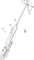
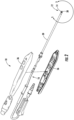
- the electrosurgical instrument 10 may include a shaft 30 extending distally from a handle 36, as shown in Figures 1 and 2 .
- the shaft 30 may have any appropriate size and configuration to support the electrode assembly 12 and to facilitate use of the electrode assembly 12 during surgical procedures.
- the handle 36 likewise may have any appropriate size and configuration to support the electrode assembly 12 and to facilitate use of the electrode assembly 12 during surgical procedures.
- the shaft 30 and handle 36 may be formed from any appropriate material.
- the electrosurgical instrument 10 may include an electrode assembly 12 formed by one or more active electrodes 14 and one or more return electrodes 38, as shown in Figures 1-6 .
- the return electrode 38 may be separated from the active electrode 14 via at least one insulator 40.
- the active electrode 14 may be positioned on a distal end 42 of the internal aspiration collection chamber 22 with at least one outer surface 42 exposed.
- the return electrode 38 may be positioned near the distal end 42 of the internal aspiration collection chamber 22 but separated from the active electrode 14 via the insulator 40.
- the return electrode 38 may be include at least one outer surface 44 exposed.
- the insulator 40 may form an internal aspiration collection chamber 22 configured to received aspirated material 18 from a surgical site 20 and to pass the aspirated material 18 on within the electrosurgical instrument 10.
- the internal aspiration collection chamber 22 may be in fluid communication with at least one aspiration inlet 46.
- the electrosurgical instrument 10 may include an aspiration system 16 for removing material 18 from a surgical site 20 whereby the aspiration system 16 includes one or more conduits 48 formed by a channel 28 extending through the shaft 30, the internal aspiration collection chamber 22 and the aspiration inlet 46.
- the outer surface 42 of the active electrode 14 may be configured to promote energy transfer between the active electrode 14 and the return electrode 38.
- the insulator 40 may be coupled to a distal tip 50 of the channel 28 of the aspiration system 16 and may support the active electrode 14.
- the active electrode 14 may include an outer surface 42, which may be substantially planar, that is nonorthogonal to a longitudinal axis 52 of the channel 28 of the aspiration system 16.
- the substantially planar outer surface 42 of the active electrode 14 may be positioned generally parallel to the longitudinal axis 52 of the channel 28 of the aspiration system 16.
- the outer surface 42 may be separated from the shaft 30 of the electrosurgical instrument 10 by the insulator 40.
- the active electrode 14 may include a support arm 26, as shown in Figures 4 and 6 , extending from the substantially planar outer surface 42 of the active electrode 14 inwardly toward the longitudinal axis 52 of the channel 28 of the aspiration system 16.
- the support arm 26 may include a threaded support orifice 54 configured to be threadably attached to threads 56 at a distal end 50 of the channel 28 of the aspiration system 20.
- the threaded support orifice 54 may couple the internal aspiration collection chamber 22 of the aspiration system 16 to the channel 28 of the aspiration system 16.
- the support arm 26 may be aligned with one or more outlets 58 of the internal aspiration collection chamber 22.
- the internal aspiration collection chamber 22 may include a single outlet 58 coupled to the channel 28.
- the outlet 58 may be, but is not limited to, having a tubular configuration.
- the single tubular outlet 58 may extend orthogonal from a sidewall forming the internal aspiration collection chamber 22.
- the single tubular outlet 58 may be configured to have minimal contact with the active electrode 14 to limit the amount of ablation heat transferred from the active electrode 14 to the proximal shaft 30 forming a portion of the internal aspiration system 16 to reduce the likelihood of tissue melting within the internal aspiration system 16.
- the internal aspiration collection chamber 22 may be formed by the insulator 40, as shown in Figures 4 and 6 .
- the insulator 40 may be formed from one or more nonconductive materials, such as, but not limited to, ceramic.
- the internal aspiration collection chamber 22 may function as the insulator 40.
- the internal aspiration collection chamber 22 may separate the active return electrodes 14, 38 and may be configured to direct aspirated materials 18, such as, but not limited to, aspirated fluids and tissue, from the surgical site 20 and into the aspiration channel 28 within the shaft 30 of the electrosurgical instrument 10.
- the ceramic internal aspiration collection chamber 22 does not absorb as much heat from the ablation process than if the component were formed from metal. As a result, the electrosurgical instrument 10 works far better than conventional systems formed from metal.
- the internal aspiration collection chamber 22 prevents tissue aspirated within the aspiration system 16 from being melted onto the walls of the aspiration system 16. In conventional systems, tissue aspirated within an aspiration system melts onto the walls of the aspiration system, thereby clogging the system. In contrast, the internal aspiration collection chamber 22 prevents clogging of the aspiration system 16 by preventing tissue aspirated within the aspiration system 16 from being melted onto the walls of the aspiration system 16.
- the internal aspiration collection chamber 22 may be configured such that a longitudinal axis 60 of the internal aspiration collection chamber 22 may be positioned nonparallel with the longitudinal axis 52 of the channel 28 of the aspiration system 16. In at least one embodiment, the longitudinal axis 60 of the internal aspiration collection chamber 22 may be positioned orthogonal to a longitudinal axis 52 of the channel 28 of the aspiration system 16.
- the internal aspiration collection chamber 22 may be an elongated chamber defined at least in part by a distal, linear surface 62, a first proximal, linear surface 64 and a second proximal, linear surface 66.
- the distal, linear surface 62 may be aligned with the first and second proximal, linear surfaces 64, 66 and are each aligned with a longitudinal axis 60 of the internal aspiration collection chamber 22, whereby the longitudinal axis 60 of the internal aspiration collection chamber 22 may be positioned orthogonal to the longitudinal axis 52 of the channel 28 of the aspiration system 16.
- the internal aspiration collection chamber 22 may be formed from a first section 68 and a second section 70, whereby the first section 68 has a larger cross-sectional area than the second section 70, and the first section 68 is positioned closer to the at least one active electrode 14 than the second section 70.
- the cross-sectional areas extend in a plane orthogonal to the longitudinal axis 60 of the internal aspiration collection chamber 22.
- the first section 68 may be positioned between the active electrode 14 and the second section 70 such that material flowing in the aspiration system 16 through the active electrode 14 first enters the first section 68 before entering the second section 70.
- the first and second sections 68, 70 may be formed, in part, by the distal, linear surface 62 extending from the active electrode 14 to a bottom surface 72 of the internal aspiration collection chamber 22.
- the shortest distance between the distal, linear surface 62 and a second proximal, linear surface 66 forming a portion of the second section 70 is less than the shortest distance between the distal, linear surface 62 and a first proximal, linear surface 64 forming a portion of the first section 68.
- the second proximal, linear surface 66 may be positioned closer to the longitudinal axis 60 of the internal aspiration collection chamber 22 than the first proximal, linear surface 64.
- the insulator 40 may be configured such that when the insulator 40 and support arm 26 are threaded onto the distal end 50 of the channel 28, the insulator 40 is firmly attached to the shaft 30 through a portion of the insulator 40 being held via interference.
- the insulator 40 may include a pocket 74 into which a portion 76 of the support arm 26 of the active electrode 14 extends.
- a proximally facing surface 80 of the active electrode 14 may contact a distally facing surface 82 of the insulator 40 and forces a proximally facing surface 84 of the insulator 40 to contact a distally facing surface 86 of the electrosurgical instrument 10, thereby securing the active electrode 14 and the insulator 40 to the shaft 30 of the electrosurgical instrument 10 by enabling the support arm 26 of the active electrode 14 to secure the insulator 40 to the shaft 30 of the electrosurgical instrument 10 when the support arm 26 of the active electrode 14 is threaded onto the shaft 30 of the electrosurgical instrument 10.
- the electrosurgical instrument 10 may be configured such that a position of the channel 28 forming a portion of the conduit 48 of the aspiration system 16 is maintained via an expanded material having been injected into a cavity 32 between the channel 28 and the shaft 30.
- the aspiration system 16 may be maintained in position within the shaft 30 via injection overmolding.
- the one or more interior cavities 32 may be injected with a liquid material that expands completely within the interior cavities 32 providing electrical insulation and structural support to the components within the outer shaft 30 of the electrosurgical instrument 10.
- the outer surface 42 of the active electrode 14 may be a roughened surface, such as, but not limited to, a sandblasted roughened surface.
- the roughened outer surface 42 of the active electrode 14 may increase the surface area and provide a more consistent performance of the electrosurgical instrument 10 at startup.
- Conventional designs without a sandblasted outer surface of the active electrode only operate consistently after about one minute of use.
- the electrosurgical instrument 10 provided consistent performance beginning at startup and did not need a warm up period.
- the electrosurgical instrument 10 may be used to ablate tissue from a surgical site 20.
- the active electrode 14 may be powered by and controlled by any appropriate electrosurgical control unit.
- the roughened outer surface 42 of the active electrode 14 operates consistently through startup conditions and at steady state operation.
- the aspiration system 16 may be activated to remove tissue, fluids and other material from the surgical site 20.
- the aspiration system 16 may be attached to a suction generator (not shown).
- the aspiration system 16 may draw materials through one or more aspiration inlets 46, which may be, but is not required to be, positioned within the active electrode 14. The materials flow through the aspiration inlet 46 and collect within the internal aspiration collection chamber 22.
- the internal aspiration collection chamber 22 is formed from one or more nonconductive materials, such as, but not limited to, ceramic, the inner surfaces, specifically, the distal, linear surface 62, the first proximal linear surface 64, the second linear surface 66 and the bottom surface 72, remain at a temperature lower than a melting point of the aspirated materials. As such, the aspirated materials do not melt in the internal aspiration collection chamber 22 and thus do not clog up the aspiration system 16. Such configuration greatly enhances the operational efficiency of the electrosurgical instrument 10.
Landscapes
- Health & Medical Sciences (AREA)
- Surgery (AREA)
- Engineering & Computer Science (AREA)
- Life Sciences & Earth Sciences (AREA)
- Biomedical Technology (AREA)
- Molecular Biology (AREA)
- Nuclear Medicine, Radiotherapy & Molecular Imaging (AREA)
- Plasma & Fusion (AREA)
- Physics & Mathematics (AREA)
- Heart & Thoracic Surgery (AREA)
- Medical Informatics (AREA)
- Otolaryngology (AREA)
- Animal Behavior & Ethology (AREA)
- General Health & Medical Sciences (AREA)
- Public Health (AREA)
- Veterinary Medicine (AREA)
- Neurology (AREA)
- Neurosurgery (AREA)
- Surgical Instruments (AREA)
Description
- The disclosure relates generally to electrosurgical medical devices, and more particularly, to electrosurgical medical devices configured to ablate tissue on patients in surgical procedures. Such electrosurgical medical devices are known e.g. from
US 2010/082026 A1 which may disclose the features of the preamble of the independent claims, fromUS 2015/245862 A1 ,US 2010/042095A1 andUS 2007/106288 A1 - Ablation devices have been used to remove tissue within patients in a variety of medical procedures. Many ablation devices include aspiration systems for removing ablated tissue and fluids from surgical sites. Some devices include aspiration systems within the ablation handpiece and include aspiration inlets at a distal tip of the ablation handpiece. The ablation materials are aspirated through the aspiration inlets at a distal tip and into the aspiration system, where the material is collected and later removed. Many of these conventional aspiration systems clog up and become unusable during surgical procedures. Often times, aspects of the aspiration system at a distal tip of an ablation handpiece becomes clogged because those aspects of the aspiration system are heated by the active electrode to such an extent that the aspirated materials in the aspiration system melt to the walls of the aspiration system. The melted aspiration material proves to be very problematic for the ablation devices. Thus, a need exists for a more robust aspiration system for a handheld ablation device.
- An electrosurgical instrument for the treatment of tissue via an electrode assembly is disclosed having at least one active electrode and an aspiration system for configured to collect aspirated materials and to remove those aspirated materials from a surgical site while preventing the materials from melting and thereby clogging the aspiration system. In at least one embodiment, the aspiration system may include an internal aspiration collection chamber positioned at a distal end of the instrument to collect aspirated material and insulate the aspirated material to prevent the aspirated material from melting within the aspiration system and thereby clogging the aspiration system. The internal aspiration collection chamber may also be subjected to reduced heating from the active electrode by limiting the exposure of the internal aspiration collection chamber to a minimally sized support arm extending from active electrode to the channel of the aspiration system positioned within the shaft of the electrosurgical instrument. The aspiration system may be formed from one or more insulating materials to reduce, if not eliminate, melting of aspirated materials. The aspiration system may be maintained in position within the shaft of the electrosurgical instrument via an expanded material having been injected into a cavity between the aspiration system and the shaft. The electrosurgical instrument may also be configured to operate more efficiently than conventional systems via the active electrode having a sandblasted roughened surface to provide consistent performance beginning at startup without need for a warm up period.
- In at least one embodiment, the electrosurgical instrument for the treatment of tissue may include a shaft, an electrode assembly, one or more active electrodes and one or more return electrode separated from the active electrode via at least one insulator. The electrosurgical instrument may include one or more insulators forming an internal aspiration collection chamber configured to received aspirated material from a surgical site and to pass the aspirated material on within the electrosurgical instrument. The internal aspiration collection chamber may be in fluid communication with one or more aspiration inlets. The electrosurgical instrument may include an aspiration system for removing material from a surgical site, the aspiration system including one or more conduits formed by a channel extending through the shaft, the internal aspiration collection chamber and the aspiration inlet.
- The insulator may be formed from a nonconductive material, such as, but not limited to, ceramic, to maintain a temperature below a lowest melting point of any material within the aspirated materials. The insulator may be coupled to a distal tip of the channel of the aspiration system and support the active electrode having a substantially planar outer surface that is nonorthogonal to a longitudinal axis of the channel of the aspiration system. The substantially planar outer surface of the at least one active electrode may be positioned generally parallel to the longitudinal axis of the channel of the aspiration system. The outer surface of the active electrode may be separated from the shaft of the electrosurgical instrument by the insulator.
- The active electrode may include a support arm extending from a substantially planar outer surface of the active electrode inwardly toward a longitudinal axis of the channel of the aspiration system whereby the support arm includes a threaded support orifice configured to be threadably attached to threads at a distal end of the channel of the aspiration system. The threaded support orifice may couple the internal aspiration collection chamber of the aspiration system to the conduit of the aspiration system.
- A longitudinal axis of the internal aspiration collection chamber within the insulator may be positioned nonparallel with a longitudinal axis of the channel of the aspiration system. A longitudinal axis of the internal aspiration collection chamber within the at least one insulator may be positioned orthogonal with a longitudinal axis of the channel of the aspiration system. The internal aspiration collection chamber may be an elongated chamber defined at least in part by a distal, linear surface, a first proximal, linear surface and a second proximal, linear surface. The distal, linear surface may be aligned with the first and second proximal, linear surfaces and are each aligned with a longitudinal axis of the internal aspiration collection chamber, wherein the longitudinal axis of the internal aspiration collection chamber may be positioned orthogonal to a longitudinal axis of the channel of the aspiration system. The internal aspiration collection chamber may be formed from a first section and a second section, whereby the first section has a larger cross-sectional area than the second section and the first section is positioned closer to the active electrode than the second section. The insulator may include a pocket into which a portion of the support arm of the active electrode extends, wherein a proximally facing surface of the active electrode contacts a distally facing surface of the insulator and forces a proximally facing surface of the insulator to contact a distally facing surface of the electrosurgical instrument, thereby securing the active electrode and the insulator to the shaft of the electrosurgical instrument by enabling the support arm of the active electrode to secure the insulator to the shaft of the electrosurgical instrument when the support arm of the active electrode is threaded onto the shaft of the electrosurgical instrument.
- The electrosurgical instrument may also be configured to operate more efficiently than conventional systems via the active electrode having a roughened surface, such as, but not limited to, a sandblasted outer surface, to provide consistent performance beginning at startup without need for a warm up period. With a roughened surface, the active electrode operates consistently throughout the startup period and through steady state operations.
- The electrosurgical instrument may be configured such that a position of the channel forming a portion of the conduit of the aspiration system is maintained via an expanded material having been injected into a cavity between the channel and the shaft. In at least one embodiment, the aspiration system may be maintained in position within the shaft via injection overmolding.
- An advantage of the electrosurgical instrument is that the electrosurgical instrument includes a nonconductive internal aspiration collection chamber configured to collect aspirated materials and to remove those aspirated materials from a surgical site while preventing the aspirated materials from melting and thereby clogging the aspiration system.
- Another advantage of the electrosurgical instrument is that the insulator forming the internal aspiration collection chamber has minimal contact with the active electrode, thereby reducing heating of the insulator and the internal aspiration collection chamber.
- Yet another advantage of the electrosurgical instrument is that the active electrode includes a roughened surface, such as, but not limited to, a sandblasted outer surface, to provide consistent performance beginning at startup without need for a warm up period, thereby operating more efficiently than conventional systems.
- Another advantage of the electrosurgical instrument is that the electrosurgical instrument may be configured such that a position of the channel forming a portion of the aspiration system may be maintained via an expanded material having been injected into a cavity between the channel and the shaft, thereby nearly, if not completely, eliminating any movement of components within the outer shaft of the electrosurgical instrument.
- These and other embodiments are described in more detail below.
-
-
Figure 1 is a perspective view of the electrosurgical instrument for the treatment of tissue via an electrode assembly. -
Figure 2 is an exploded perspective view of the electrosurgical instrument shown inFigure 1 . -
Figure 3 is a detail view of a distal end of the electrosurgical instrument taken at detail line 3-3 inFigure 2 . -
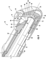
Figure 4 is a cross-sectional, perspective view of the distal end of the electrosurgical instrument taken at section line 4-4 inFigure 3 . -
Figure 5 is a side view of the distal end of the electrosurgical instrument. -
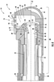
Figure 6 is a cross-sectional, side view of the distal end of the electrosurgical instrument taken at section line 4-4 inFigure 3 . - As shown in
Figures 1-6 , anelectrosurgical instrument 10 for the treatment of tissue via anelectrode assembly 12 is disclosed having at least oneactive electrode 14 and anaspiration system 16 for configured to collect aspirated materials and to remove those aspiratedmaterials 18 from asurgical site 20 while preventing thematerials 18 from melting and thereby clogging theaspiration system 16. In at least one embodiment, theaspiration system 16 may include an internalaspiration collection chamber 22 positioned at adistal end 24 of theinstrument 10 to collect aspiratedmaterial 18 and insulate the aspiratedmaterial 18 to prevent the aspiratedmaterial 18 from melting within theaspiration system 16 and thereby clogging theaspiration system 16. The internalaspiration collection chamber 22 may also be subjected to reduced heating from theactive electrode 14 by limiting the exposure of the internalaspiration collection chamber 22 to a minimally sizedsupport arm 26 extending fromactive electrode 14 to thechannel 28 of theaspiration system 16 positioned within theshaft 30 of theelectrosurgical instrument 10. Theaspiration system 16 may be formed from one or more insulating materials to reduce, if not eliminate, melting of aspirated materials. Theaspiration system 16 may be maintained in position within theshaft 30 of theelectrosurgical instrument 10 via an expanded material having been injected into acavity 32 between theaspiration system 16 and theshaft 30. Theelectrosurgical instrument 10 may also be configured to operate more efficiently than conventional systems via theactive electrode 14 having a sandblasted roughenedsurface 42 to provide consistent performance beginning at startup without need for a warm up period. - In at least one embodiment, the
electrosurgical instrument 10 may include ashaft 30 extending distally from ahandle 36, as shown inFigures 1 and2 . Theshaft 30 may have any appropriate size and configuration to support theelectrode assembly 12 and to facilitate use of theelectrode assembly 12 during surgical procedures. Thehandle 36 likewise may have any appropriate size and configuration to support theelectrode assembly 12 and to facilitate use of theelectrode assembly 12 during surgical procedures. Theshaft 30 andhandle 36 may be formed from any appropriate material. - The
electrosurgical instrument 10 may include anelectrode assembly 12 formed by one or moreactive electrodes 14 and one ormore return electrodes 38, as shown inFigures 1-6 . Thereturn electrode 38 may be separated from theactive electrode 14 via at least oneinsulator 40. Theactive electrode 14 may be positioned on adistal end 42 of the internalaspiration collection chamber 22 with at least oneouter surface 42 exposed. Thereturn electrode 38 may be positioned near thedistal end 42 of the internalaspiration collection chamber 22 but separated from theactive electrode 14 via theinsulator 40. Thereturn electrode 38 may be include at least oneouter surface 44 exposed. In at least one embodiment, theinsulator 40 may form an internalaspiration collection chamber 22 configured to receivedaspirated material 18 from asurgical site 20 and to pass the aspiratedmaterial 18 on within theelectrosurgical instrument 10. The internalaspiration collection chamber 22 may be in fluid communication with at least oneaspiration inlet 46. Theelectrosurgical instrument 10 may include anaspiration system 16 for removingmaterial 18 from asurgical site 20 whereby theaspiration system 16 includes one ormore conduits 48 formed by achannel 28 extending through theshaft 30, the internalaspiration collection chamber 22 and theaspiration inlet 46. - In at least one embodiment, the
outer surface 42 of theactive electrode 14 may be configured to promote energy transfer between theactive electrode 14 and thereturn electrode 38. Theinsulator 40 may be coupled to adistal tip 50 of thechannel 28 of theaspiration system 16 and may support theactive electrode 14. Theactive electrode 14 may include anouter surface 42, which may be substantially planar, that is nonorthogonal to alongitudinal axis 52 of thechannel 28 of theaspiration system 16. The substantially planarouter surface 42 of theactive electrode 14 may be positioned generally parallel to thelongitudinal axis 52 of thechannel 28 of theaspiration system 16. Theouter surface 42 may be separated from theshaft 30 of theelectrosurgical instrument 10 by theinsulator 40. - In at least one embodiment, the
active electrode 14 may include asupport arm 26, as shown inFigures 4 and6 , extending from the substantially planarouter surface 42 of theactive electrode 14 inwardly toward thelongitudinal axis 52 of thechannel 28 of theaspiration system 16. Thesupport arm 26 may include a threadedsupport orifice 54 configured to be threadably attached tothreads 56 at adistal end 50 of thechannel 28 of theaspiration system 20. The threadedsupport orifice 54 may couple the internalaspiration collection chamber 22 of theaspiration system 16 to thechannel 28 of theaspiration system 16. In at least one embodiment, thesupport arm 26 may be aligned with one ormore outlets 58 of the internalaspiration collection chamber 22. In at least one embodiment, the internalaspiration collection chamber 22 may include asingle outlet 58 coupled to thechannel 28. Theoutlet 58 may be, but is not limited to, having a tubular configuration. The singletubular outlet 58 may extend orthogonal from a sidewall forming the internalaspiration collection chamber 22. The singletubular outlet 58 may be configured to have minimal contact with theactive electrode 14 to limit the amount of ablation heat transferred from theactive electrode 14 to theproximal shaft 30 forming a portion of theinternal aspiration system 16 to reduce the likelihood of tissue melting within theinternal aspiration system 16. - In at least one embodiment, the internal
aspiration collection chamber 22 may be formed by theinsulator 40, as shown inFigures 4 and6 . Theinsulator 40 may be formed from one or more nonconductive materials, such as, but not limited to, ceramic. In at least one embodiment, the internalaspiration collection chamber 22 may function as theinsulator 40. The internalaspiration collection chamber 22 may separate theactive return electrodes materials 18, such as, but not limited to, aspirated fluids and tissue, from thesurgical site 20 and into theaspiration channel 28 within theshaft 30 of theelectrosurgical instrument 10. In embodiments in which internalaspiration collection chamber 22 is formed from ceramic, the ceramic internalaspiration collection chamber 22 does not absorb as much heat from the ablation process than if the component were formed from metal. As a result, theelectrosurgical instrument 10 works far better than conventional systems formed from metal. The internalaspiration collection chamber 22 prevents tissue aspirated within theaspiration system 16 from being melted onto the walls of theaspiration system 16. In conventional systems, tissue aspirated within an aspiration system melts onto the walls of the aspiration system, thereby clogging the system. In contrast, the internalaspiration collection chamber 22 prevents clogging of theaspiration system 16 by preventing tissue aspirated within theaspiration system 16 from being melted onto the walls of theaspiration system 16. - The internal
aspiration collection chamber 22 may be configured such that alongitudinal axis 60 of the internalaspiration collection chamber 22 may be positioned nonparallel with thelongitudinal axis 52 of thechannel 28 of theaspiration system 16. In at least one embodiment, thelongitudinal axis 60 of the internalaspiration collection chamber 22 may be positioned orthogonal to alongitudinal axis 52 of thechannel 28 of theaspiration system 16. The internalaspiration collection chamber 22 may be an elongated chamber defined at least in part by a distal,linear surface 62, a first proximal,linear surface 64 and a second proximal,linear surface 66. The distal,linear surface 62 may be aligned with the first and second proximal,linear surfaces longitudinal axis 60 of the internalaspiration collection chamber 22, whereby thelongitudinal axis 60 of the internalaspiration collection chamber 22 may be positioned orthogonal to thelongitudinal axis 52 of thechannel 28 of theaspiration system 16. As shown inFigure 6 , the internalaspiration collection chamber 22 may be formed from afirst section 68 and a second section 70, whereby thefirst section 68 has a larger cross-sectional area than the second section 70, and thefirst section 68 is positioned closer to the at least oneactive electrode 14 than the second section 70. The cross-sectional areas extend in a plane orthogonal to thelongitudinal axis 60 of the internalaspiration collection chamber 22. Thefirst section 68 may be positioned between theactive electrode 14 and the second section 70 such that material flowing in theaspiration system 16 through theactive electrode 14 first enters thefirst section 68 before entering the second section 70. The first andsecond sections 68, 70 may be formed, in part, by the distal,linear surface 62 extending from theactive electrode 14 to abottom surface 72 of the internalaspiration collection chamber 22. The shortest distance between the distal,linear surface 62 and a second proximal,linear surface 66 forming a portion of the second section 70 is less than the shortest distance between the distal,linear surface 62 and a first proximal,linear surface 64 forming a portion of thefirst section 68. As such, the second proximal,linear surface 66 may be positioned closer to thelongitudinal axis 60 of the internalaspiration collection chamber 22 than the first proximal,linear surface 64. - The
insulator 40 may be configured such that when theinsulator 40 andsupport arm 26 are threaded onto thedistal end 50 of thechannel 28, theinsulator 40 is firmly attached to theshaft 30 through a portion of theinsulator 40 being held via interference. In particular, as shown inFigure 6 , theinsulator 40 may include apocket 74 into which aportion 76 of thesupport arm 26 of theactive electrode 14 extends. Aproximally facing surface 80 of theactive electrode 14 may contact adistally facing surface 82 of theinsulator 40 and forces a proximally facing surface 84 of theinsulator 40 to contact adistally facing surface 86 of theelectrosurgical instrument 10, thereby securing theactive electrode 14 and theinsulator 40 to theshaft 30 of theelectrosurgical instrument 10 by enabling thesupport arm 26 of theactive electrode 14 to secure theinsulator 40 to theshaft 30 of theelectrosurgical instrument 10 when thesupport arm 26 of theactive electrode 14 is threaded onto theshaft 30 of theelectrosurgical instrument 10. - The
electrosurgical instrument 10 may be configured such that a position of thechannel 28 forming a portion of theconduit 48 of theaspiration system 16 is maintained via an expanded material having been injected into acavity 32 between thechannel 28 and theshaft 30. In particular, theaspiration system 16 may be maintained in position within theshaft 30 via injection overmolding. For instance, after theelectrosurgical instrument 10 has been assembled with thechannel 28 of thefluid aspiration system 16 installed within the outertubular shaft 30 and thedistal tip 88, formed from theinsulator 40 with theactive electrode 14 and returnelectrode 38, attached to thefluid aspiration channel 28 and the outer tubular housing, the one or moreinterior cavities 32 may be injected with a liquid material that expands completely within theinterior cavities 32 providing electrical insulation and structural support to the components within theouter shaft 30 of theelectrosurgical instrument 10. - In at least one embodiment, the
outer surface 42 of theactive electrode 14 may be a roughened surface, such as, but not limited to, a sandblasted roughened surface. The roughenedouter surface 42 of theactive electrode 14 may increase the surface area and provide a more consistent performance of theelectrosurgical instrument 10 at startup. Conventional designs without a sandblasted outer surface of the active electrode only operate consistently after about one minute of use. When the outer surface of theactive electrode 14 is sandblasted, theelectrosurgical instrument 10 provided consistent performance beginning at startup and did not need a warm up period. - During use, the
electrosurgical instrument 10 may be used to ablate tissue from asurgical site 20. Theactive electrode 14 may be powered by and controlled by any appropriate electrosurgical control unit. The roughenedouter surface 42 of theactive electrode 14 operates consistently through startup conditions and at steady state operation. While theactive electrode 14 is ablating tissue, theaspiration system 16 may be activated to remove tissue, fluids and other material from thesurgical site 20. Theaspiration system 16 may be attached to a suction generator (not shown). Theaspiration system 16 may draw materials through one ormore aspiration inlets 46, which may be, but is not required to be, positioned within theactive electrode 14. The materials flow through theaspiration inlet 46 and collect within the internalaspiration collection chamber 22. Because the internalaspiration collection chamber 22 is formed from one or more nonconductive materials, such as, but not limited to, ceramic, the inner surfaces, specifically, the distal,linear surface 62, the first proximallinear surface 64, the secondlinear surface 66 and thebottom surface 72, remain at a temperature lower than a melting point of the aspirated materials. As such, the aspirated materials do not melt in the internalaspiration collection chamber 22 and thus do not clog up theaspiration system 16. Such configuration greatly enhances the operational efficiency of theelectrosurgical instrument 10. - The foregoing is provided for purposes of illustrating, explaining, and describing embodiments of this invention. Modifications and adaptations to these embodiments will be apparent to those skilled in the art.
Claims (20)
- An electrosurgical instrument (10) for the treatment of tissue, comprising:a shaft (30);an electrode assembly(12), comprising:at least one active electrode (14);at least one return electrode (38) separated from the active electrode (14) via at least one insulator (40); andan aspiration system (16) for removing material (18) from a surgical site (20), the aspiration system (16) including at least one conduit (48) formed by a channel (28) extending through the shaft,(30) and at least one aspiration inlet (46),characterized in that the at least one active electrode (14) includes a support arm (26) extending from an outer surface of the at least one active electrode (14) inwardly toward a longitudinal axis (52) of the channel (28) of the aspiration system (16) whereby the support arm (26) includes a threaded support orifice (54) configured to be threadably attached to threads (56) at a distal end of the channel (28) of the aspiration system (16).
- The electrosurgical instrument (10) of claim 1, wherein the aspiration system (16) for removing material (18) from a surgical site (20), includes an internal aspiration collection chamber (26), said internal aspiration collection chamber (26) being in fluid communication with at least one aspiration inlet (46).
- The electrosurgical instrument (10) of claim 2, wherein the at least one insulator (40) forms the internal aspiration collection chamber (26) configured to received aspirated material (18) from a surgical site (20) and to pass the aspirated material (18) on within the electrosurgical instrument (10);
- The electrosurgical instrument (10) of claim 3, wherein the at least one insulator (40) is coupled to a distal tip of the channel (28) of the aspiration system (16) and supports the at least one active electrode (14) with an outer surface that is nonorthogonal to a longitudinal axis (52) of the channel (28) of the aspiration system (16).
- The electrosurgical instrument (10) of claim 4, wherein the outer surface of the at least one active electrode (14) is positioned generally parallel to the longitudinal axis (52) of the channel (28) of the aspiration system (16).
- The electrosurgical instrument (10) of claim 3, wherein the at least one insulator (40) is coupled to a distal tip of the channel (28) of the aspiration system (16) and supports the at least one active electrode (14) with an outer surface that is nonorthogonal to a longitudinal axis of the shaft (30) of the electrosurgical instrument (10).
- The electrosurgical instrument (10) of claim 1, wherein an outer surface of the at least one active electrode (14) is separated from the shaft (30) of the electrosurgical instrument (10) by the at least one insulator (40).
- The electrosurgical instrument (10) of claim 1, wherein the threaded support orifice (54) couples the internal aspiration collection chamber (22) of the aspiration system (16) to the at least one channel (28) of the aspiration system (16).
- The electrosurgical instrument (10) of claim 1, wherein a longitudinal axis (60) of the internal aspiration collection chamber (22) is positioned nonparallel with the longitudinal axis (52) of the channel (28) of the aspiration system (16).
- The electrosurgical instrument (10) of claim 1, wherein the longitudinal axis (60) of the internal aspiration , collection chamber (22) is positioned orthogonal with a longitudinal axis (52) of the channel (28) of the aspiration system (16).
- The electrosurgical instrument (10) of claim 2, wherein the internal aspiration collection chamber (22) is an elongated chamber defined at least in part by a distal, linear surface (62), a first proximal, linear surface (64) and a second proximal, linear surface (66).
- The electrosurgical instrument (10) of claim 11, wherein the distal, linear surface (62) is aligned with the first and second proximal, linear surfaces (64,66) and are each aligned with a longitudinal axis (60) of the internal aspiration collection chamber (22), wherein the longitudinal axis of the internal aspiration collection chamber is positioned orthogonal to a longitudinal axis (52) of the channel (28) of the aspiration system (16).
- The electrosurgical instrument (10) of claim 11, wherein the internal aspiration collection chamber (22) is formed from a first section (68) and a second section (70), whereby the first section (68) has a larger cross-sectional area than the second section (70) and the first section (68) is positioned closer to the at least one active electrode (14) than the second section (70).
- The electrosurgical instrument (10) of claim 1, wherein the at least one insulator (40) includes a pocket (74) into which a portion (76) of the support arm (26) of the active electrode (14) extends, wherein a proximally facing surface (80) of the active electrode (14) contacts a distally facing surface (82) of the at least one insulator (40) and forces a proximally facing surface (84) of the at least one insulator to contact a distally facing surface (86) of the electrosurgical instrument (10), thereby securing the active electrode (14) and the at least one insulator (40) to the shaft (30) of the electrosurgical instrument (10) by enabling the support arm (26) of the active electrode (14) to secure the at least one insulator (40) to the shaft (30) of the electrosurgical instrument (10) when the support arm (26) of the active electrode (14) is threaded onto the shaft (30) of the electrosurgical instrument (10).
- The electrosurgical instrument (10) of claim 1, wherein an outer surface of the active electrode (14) is a sandblasted roughened surface.
- The electrosurgical instrument (10) of claim 1, wherein the at least one insulator (40) is formed from ceramic.
- The electrosurgical instrument (10) of claim 1, wherein a position of the channel (28) forming a portion of the conduit (48) of the aspiration system (16) is maintained via an expanded material having been injected into a cavity (32) between the channel (28) and the shaft (30).
- The electrosurgical instrument (10) of claim 6, wherein the outer surface of the at least one active electrode (14) is positioned generally parallel to the longitudinal axis (52) of the channel (28) of the aspiration system (16), wherein the outer surface of the at least one active electrode (40) is separated from the shaft (30) of the electrosurgical instrument (10) by the at least one insulator (40), and wherein the threaded support orifice (54) couples the internal aspiration collection chamber (22) of the aspiration system (16) to the at least one conduit (48) of the aspiration system (16).
- The electrosurgical instrument (10) of claim 6, wherein the internal aspiration collection chamber (22) is an elongated chamber defined at least in part by a distal, linear surface (62), a first proximal, linear surface (64) and a second proximal, linear surface (66), wherein the distal, linear surface (62) is aligned with the first and second proximal, linear surfaces (64,66) and are each aligned with a longitudinal axis (60) of the internal aspiration collection chamber (22), wherein the longitudinal axis (60) of the internal aspiration collection chamber (22) is positioned orthogonal to a longitudinal axis (52) of the channel (28) of the aspiration system (22), and wherein the internal aspiration collection chamber (22) is formed from a first section (68) and a second section (70), whereby the first section (68) has a larger cross-sectional area than the second section (70) and the first section (68) is positioned closer to the at least one active electrode (14).
- An electrosurgical instrument (10) for the treatment of tissue, comprising:a shaft (30);an electrode assembly (12), comprising:at least one active electrode (14);at least one return electrode (38) separated from the active electrode (14) via at least one insulator (40); andan aspiration system (16) for removing material (18) from a surgical site (20), the aspiration system (16) including at least one conduit (48) formed by a channel (28) extending through the shaft (30), and at least one aspiration inlet (46),characterized in that the at least one insulator (40) includes a pocket into which a portion of the support arm (26) of the active electrode (14) extends, wherein a proximally facing surface (80) of the active electrode (14) contacts a distally facing surface (82) of the at least one insulator (40) and forces a proximally facing surface (84) of the at least one insulator (40) to contact a distally facing surface (86) of the electrosurgical instrument (10), thereby securing the active electrode (14) and the at least one insulator (40) to the shaft (30) of the electrosurgical instrument (10) by enabling the support arm (26) of the active electrode (14) to secure the at least one insulator (40) to the shaft (30) of the electrosurgical instrument (10) when the support arm (26) of the active electrode (14) is threaded onto the shaft (30) of the electrosurgical instrument (10).
Applications Claiming Priority (2)
| Application Number | Priority Date | Filing Date | Title |
|---|---|---|---|
| US15/357,560 US10335225B2 (en) | 2016-11-21 | 2016-11-21 | Electrosurgical medical device handpiece with insulated aspiration system |
| PCT/US2017/048114 WO2018093433A1 (en) | 2016-11-21 | 2017-08-23 | Electrosurgical medical device handpiece with insulated aspiration system |
Publications (3)
| Publication Number | Publication Date |
|---|---|
| EP3541296A1 EP3541296A1 (en) | 2019-09-25 |
| EP3541296A4 EP3541296A4 (en) | 2020-09-23 |
| EP3541296B1 true EP3541296B1 (en) | 2023-06-07 |
Family
ID=62144115
Family Applications (1)
| Application Number | Title | Priority Date | Filing Date |
|---|---|---|---|
| EP17870828.5A Active EP3541296B1 (en) | 2016-11-21 | 2017-08-23 | Electrosurgical medical device handpiece with insulated aspiration system |
Country Status (6)
| Country | Link |
|---|---|
| US (1) | US10335225B2 (en) |
| EP (1) | EP3541296B1 (en) |
| JP (1) | JP7010963B2 (en) |
| CN (1) | CN110167456B (en) |
| CA (1) | CA3041618C (en) |
| WO (1) | WO2018093433A1 (en) |
Families Citing this family (2)
| Publication number | Priority date | Publication date | Assignee | Title |
|---|---|---|---|---|
| WO2023076579A1 (en) * | 2021-10-29 | 2023-05-04 | Arthrex, Inc. | Surgical device system |
| WO2024042422A1 (en) * | 2022-08-25 | 2024-02-29 | Arthrex, Inc. | Ablation probe and lumen for improved access and flow |
Family Cites Families (47)
| Publication number | Priority date | Publication date | Assignee | Title |
|---|---|---|---|---|
| US3630203A (en) * | 1969-12-11 | 1971-12-28 | Air Prod & Chem | Cryogenic biological apparatus |
| US4936281A (en) | 1989-04-13 | 1990-06-26 | Everest Medical Corporation | Ultrasonically enhanced RF ablation catheter |
| US5454787A (en) * | 1991-02-15 | 1995-10-03 | Lundquist; Ingemar H. | Torquable tubular assembly and torquable catheter utilizing the same |
| US6296638B1 (en) | 1993-05-10 | 2001-10-02 | Arthrocare Corporation | Systems for tissue ablation and aspiration |
| US5902272A (en) | 1992-01-07 | 1999-05-11 | Arthrocare Corporation | Planar ablation probe and method for electrosurgical cutting and ablation |
| US5697882A (en) * | 1992-01-07 | 1997-12-16 | Arthrocare Corporation | System and method for electrosurgical cutting and ablation |
| US5843019A (en) * | 1992-01-07 | 1998-12-01 | Arthrocare Corporation | Shaped electrodes and methods for electrosurgical cutting and ablation |
| US5486161A (en) | 1993-02-02 | 1996-01-23 | Zomed International | Medical probe device and method |
| US6044846A (en) * | 1994-06-24 | 2000-04-04 | Edwards; Stuart D. | Method to treat esophageal sphincters |
| CA2224975A1 (en) | 1995-06-23 | 1997-01-09 | Gyrus Medical Limited | An electrosurgical instrument |
| US6013076A (en) | 1996-01-09 | 2000-01-11 | Gyrus Medical Limited | Electrosurgical instrument |
| US6726684B1 (en) | 1996-07-16 | 2004-04-27 | Arthrocare Corporation | Methods for electrosurgical spine surgery |
| US5941893A (en) | 1996-12-02 | 1999-08-24 | Angiotrax, Inc. | Apparatus for transluminally performing surgery |
| GB2327352A (en) | 1997-07-18 | 1999-01-27 | Gyrus Medical Ltd | Electrosurgical instrument |
| US6517534B1 (en) | 1998-02-11 | 2003-02-11 | Cosman Company, Inc. | Peri-urethral ablation |
| GB9807303D0 (en) | 1998-04-03 | 1998-06-03 | Gyrus Medical Ltd | An electrode assembly for an electrosurgical instrument |
| US6890332B2 (en) | 1999-05-24 | 2005-05-10 | Csaba Truckai | Electrical discharge devices and techniques for medical procedures |
| US6394956B1 (en) | 2000-02-29 | 2002-05-28 | Scimed Life Systems, Inc. | RF ablation and ultrasound catheter for crossing chronic total occlusions |
| US6743226B2 (en) | 2001-02-09 | 2004-06-01 | Cosman Company, Inc. | Adjustable trans-urethral radio-frequency ablation |
| EP1379187A2 (en) | 2001-04-18 | 2004-01-14 | Smith & Nephew, Inc. | Electrosurgery systems |
| JP4994573B2 (en) * | 2002-02-12 | 2012-08-08 | オラテック インターベンションズ インコーポレイテッド | Endoscopic high-frequency ablation device |
| US6878149B2 (en) | 2002-03-25 | 2005-04-12 | Acueity, Inc. | Apparatus and method for intraductal abalation |
| US7563261B2 (en) | 2003-08-11 | 2009-07-21 | Electromedical Associates Llc | Electrosurgical device with floating-potential electrodes |
| DE202004021947U1 (en) | 2003-09-12 | 2013-05-13 | Vessix Vascular, Inc. | Selectable eccentric remodeling and / or ablation of atherosclerotic material |
| US7708733B2 (en) | 2003-10-20 | 2010-05-04 | Arthrocare Corporation | Electrosurgical method and apparatus for removing tissue within a bone body |
| US20060259025A1 (en) | 2005-05-16 | 2006-11-16 | Arthrocare Corporation | Conductive fluid bridge electrosurgical apparatus |
| US9486274B2 (en) * | 2005-09-07 | 2016-11-08 | Ulthera, Inc. | Dissection handpiece and method for reducing the appearance of cellulite |
| US20070106288A1 (en) | 2005-11-09 | 2007-05-10 | Arthrocare Corporation | Electrosurgical apparatus with fluid flow regulator |
| US7879034B2 (en) | 2006-03-02 | 2011-02-01 | Arthrocare Corporation | Internally located return electrode electrosurgical apparatus, system and method |
| WO2007106740A2 (en) | 2006-03-13 | 2007-09-20 | Baxano, Inc. | Methods and apparatus for tissue modification |
| GB2451623A (en) * | 2007-08-03 | 2009-02-11 | Gyrus Medical Ltd | Electrosurgical Instrument for underwater surgery with aspiration aperture in electrode |
| US8066704B2 (en) | 2008-06-20 | 2011-11-29 | Linvatec Corporation | Suction ablator |
| US8328804B2 (en) * | 2008-07-24 | 2012-12-11 | Covidien Lp | Suction coagulator |
| US8747400B2 (en) * | 2008-08-13 | 2014-06-10 | Arthrocare Corporation | Systems and methods for screen electrode securement |
| GB0817920D0 (en) * | 2008-09-30 | 2008-11-05 | Gyrus Medical Ltd | Electrosurgical instrument and system |
| US9259234B2 (en) | 2010-02-11 | 2016-02-16 | Ethicon Endo-Surgery, Llc | Ultrasonic surgical instruments with rotatable blade and hollow sheath arrangements |
| US9011426B2 (en) | 2010-04-22 | 2015-04-21 | Electromedical Associates, Llc | Flexible electrosurgical ablation and aspiration electrode with beveled active surface |
| US20120179157A1 (en) * | 2011-01-06 | 2012-07-12 | Andrew Frazier | Systems and methods for screen electrode securement |
| US9259216B2 (en) * | 2011-01-14 | 2016-02-16 | DePuy Synthes Products, Inc. | Elongated fixation element |
| US9168082B2 (en) | 2011-02-09 | 2015-10-27 | Arthrocare Corporation | Fine dissection electrosurgical device |
| US9271784B2 (en) | 2011-02-09 | 2016-03-01 | Arthrocare Corporation | Fine dissection electrosurgical device |
| US9113882B2 (en) * | 2012-01-23 | 2015-08-25 | Covidien Lp | Method of manufacturing an electrosurgical instrument |
| CN107693114A (en) | 2012-04-24 | 2018-02-16 | 西比姆公司 | The catheter in blood vessel and method extractd for carotid body |
| US9254166B2 (en) * | 2013-01-17 | 2016-02-09 | Arthrocare Corporation | Systems and methods for turbinate reduction |
| CN203252730U (en) * | 2013-04-28 | 2013-10-30 | 江苏瑞祺生命科学仪器有限公司 | Microwave therapy apparatus probe support without motion dead zone |
| US9526556B2 (en) | 2014-02-28 | 2016-12-27 | Arthrocare Corporation | Systems and methods systems related to electrosurgical wands with screen electrodes |
| EP3061415B8 (en) * | 2015-02-24 | 2017-11-22 | Covidien LP | Ultrasonic surgical instrument with cooling system |
-
2016
- 2016-11-21 US US15/357,560 patent/US10335225B2/en active Active
-
2017
- 2017-08-23 EP EP17870828.5A patent/EP3541296B1/en active Active
- 2017-08-23 CN CN201780069295.XA patent/CN110167456B/en active Active
- 2017-08-23 CA CA3041618A patent/CA3041618C/en active Active
- 2017-08-23 JP JP2019547571A patent/JP7010963B2/en active Active
- 2017-08-23 WO PCT/US2017/048114 patent/WO2018093433A1/en not_active Ceased
Also Published As
| Publication number | Publication date |
|---|---|
| CA3041618C (en) | 2021-11-02 |
| EP3541296A1 (en) | 2019-09-25 |
| JP7010963B2 (en) | 2022-01-26 |
| EP3541296A4 (en) | 2020-09-23 |
| US20180140349A1 (en) | 2018-05-24 |
| CN110167456A (en) | 2019-08-23 |
| US10335225B2 (en) | 2019-07-02 |
| JP2020500671A (en) | 2020-01-16 |
| CN110167456B (en) | 2022-04-15 |
| CA3041618A1 (en) | 2018-05-24 |
| WO2018093433A1 (en) | 2018-05-24 |
Similar Documents
| Publication | Publication Date | Title |
|---|---|---|
| EP1304084B1 (en) | Electrosurgical ablator with aspiration | |
| US20260007460A1 (en) | Tissue extraction devices and methods | |
| EP3777726B1 (en) | Tissue extraction systems | |
| JP6814746B2 (en) | Medical ablation device and usage | |
| EP1797839B1 (en) | Aspirating electrosurgical probe with aspiration through electrode face | |
| EP2147651B1 (en) | Suction coagulator with thermal insulation | |
| US4719914A (en) | Electrosurgical instrument | |
| US10695120B2 (en) | Adapter element, HF surgical instrument, adapter attachment and system | |
| US7611509B2 (en) | Electrosurgical device | |
| JP5167443B2 (en) | Medical liquid delivery device | |
| US7699846B2 (en) | Surgical instrument and method | |
| EP2156803B1 (en) | Insulated tube for a suction coagulator | |
| EP1223877B1 (en) | Surgical instrument for ablation and aspiration | |
| US7563261B2 (en) | Electrosurgical device with floating-potential electrodes | |
| CA3041618C (en) | Electrosurgical medical device handpiece with insulated aspiration system | |
| WO2011133767A1 (en) | Flexible electrosurgical ablation and aspiration electrode with beveled active surface | |
| US20150196350A1 (en) | Electrosurgical devices having enhanced effectiveness and methods of making and using same | |
| WO2015045431A1 (en) | Probe unit, treatment tool and treatment system | |
| KR20050100996A (en) | Electrode for radiofrequency tissue ablation |
Legal Events
| Date | Code | Title | Description |
|---|---|---|---|
| STAA | Information on the status of an ep patent application or granted ep patent |
Free format text: STATUS: THE INTERNATIONAL PUBLICATION HAS BEEN MADE |
|
| PUAI | Public reference made under article 153(3) epc to a published international application that has entered the european phase |
Free format text: ORIGINAL CODE: 0009012 |
|
| STAA | Information on the status of an ep patent application or granted ep patent |
Free format text: STATUS: REQUEST FOR EXAMINATION WAS MADE |
|
| 17P | Request for examination filed |
Effective date: 20190417 |
|
| AK | Designated contracting states |
Kind code of ref document: A1 Designated state(s): AL AT BE BG CH CY CZ DE DK EE ES FI FR GB GR HR HU IE IS IT LI LT LU LV MC MK MT NL NO PL PT RO RS SE SI SK SM TR |
|
| AX | Request for extension of the european patent |
Extension state: BA ME |
|
| DAV | Request for validation of the european patent (deleted) | ||
| DAX | Request for extension of the european patent (deleted) | ||
| A4 | Supplementary search report drawn up and despatched |
Effective date: 20200821 |
|
| RIC1 | Information provided on ipc code assigned before grant |
Ipc: A61B 18/14 20060101ALI20200817BHEP Ipc: A61B 18/04 20060101ALI20200817BHEP Ipc: A61B 17/00 20060101AFI20200817BHEP Ipc: A61B 18/12 20060101ALI20200817BHEP Ipc: A61B 18/18 20060101ALI20200817BHEP Ipc: A61B 18/00 20060101ALI20200817BHEP |
|
| GRAP | Despatch of communication of intention to grant a patent |
Free format text: ORIGINAL CODE: EPIDOSNIGR1 |
|
| STAA | Information on the status of an ep patent application or granted ep patent |
Free format text: STATUS: GRANT OF PATENT IS INTENDED |
|
| INTG | Intention to grant announced |
Effective date: 20230124 |
|
| GRAS | Grant fee paid |
Free format text: ORIGINAL CODE: EPIDOSNIGR3 |
|
| GRAA | (expected) grant |
Free format text: ORIGINAL CODE: 0009210 |
|
| STAA | Information on the status of an ep patent application or granted ep patent |
Free format text: STATUS: THE PATENT HAS BEEN GRANTED |
|
| AK | Designated contracting states |
Kind code of ref document: B1 Designated state(s): AL AT BE BG CH CY CZ DE DK EE ES FI FR GB GR HR HU IE IS IT LI LT LU LV MC MK MT NL NO PL PT RO RS SE SI SK SM TR |
|
| REG | Reference to a national code |
Ref country code: GB Ref legal event code: FG4D |
|
| REG | Reference to a national code |
Ref country code: CH Ref legal event code: EP Ref country code: AT Ref legal event code: REF Ref document number: 1572407 Country of ref document: AT Kind code of ref document: T Effective date: 20230615 |
|
| REG | Reference to a national code |
Ref country code: DE Ref legal event code: R096 Ref document number: 602017069980 Country of ref document: DE |
|
| REG | Reference to a national code |
Ref country code: LT Ref legal event code: MG9D |
|
| REG | Reference to a national code |
Ref country code: NL Ref legal event code: MP Effective date: 20230607 |
|
| PG25 | Lapsed in a contracting state [announced via postgrant information from national office to epo] |
Ref country code: SE Free format text: LAPSE BECAUSE OF FAILURE TO SUBMIT A TRANSLATION OF THE DESCRIPTION OR TO PAY THE FEE WITHIN THE PRESCRIBED TIME-LIMIT Effective date: 20230607 Ref country code: NO Free format text: LAPSE BECAUSE OF FAILURE TO SUBMIT A TRANSLATION OF THE DESCRIPTION OR TO PAY THE FEE WITHIN THE PRESCRIBED TIME-LIMIT Effective date: 20230907 Ref country code: ES Free format text: LAPSE BECAUSE OF FAILURE TO SUBMIT A TRANSLATION OF THE DESCRIPTION OR TO PAY THE FEE WITHIN THE PRESCRIBED TIME-LIMIT Effective date: 20230607 |
|
| REG | Reference to a national code |
Ref country code: AT Ref legal event code: MK05 Ref document number: 1572407 Country of ref document: AT Kind code of ref document: T Effective date: 20230607 |
|
| PG25 | Lapsed in a contracting state [announced via postgrant information from national office to epo] |
Ref country code: RS Free format text: LAPSE BECAUSE OF FAILURE TO SUBMIT A TRANSLATION OF THE DESCRIPTION OR TO PAY THE FEE WITHIN THE PRESCRIBED TIME-LIMIT Effective date: 20230607 Ref country code: NL Free format text: LAPSE BECAUSE OF FAILURE TO SUBMIT A TRANSLATION OF THE DESCRIPTION OR TO PAY THE FEE WITHIN THE PRESCRIBED TIME-LIMIT Effective date: 20230607 Ref country code: LV Free format text: LAPSE BECAUSE OF FAILURE TO SUBMIT A TRANSLATION OF THE DESCRIPTION OR TO PAY THE FEE WITHIN THE PRESCRIBED TIME-LIMIT Effective date: 20230607 Ref country code: LT Free format text: LAPSE BECAUSE OF FAILURE TO SUBMIT A TRANSLATION OF THE DESCRIPTION OR TO PAY THE FEE WITHIN THE PRESCRIBED TIME-LIMIT Effective date: 20230607 Ref country code: HR Free format text: LAPSE BECAUSE OF FAILURE TO SUBMIT A TRANSLATION OF THE DESCRIPTION OR TO PAY THE FEE WITHIN THE PRESCRIBED TIME-LIMIT Effective date: 20230607 Ref country code: GR Free format text: LAPSE BECAUSE OF FAILURE TO SUBMIT A TRANSLATION OF THE DESCRIPTION OR TO PAY THE FEE WITHIN THE PRESCRIBED TIME-LIMIT Effective date: 20230908 |
|
| PG25 | Lapsed in a contracting state [announced via postgrant information from national office to epo] |
Ref country code: FI Free format text: LAPSE BECAUSE OF FAILURE TO SUBMIT A TRANSLATION OF THE DESCRIPTION OR TO PAY THE FEE WITHIN THE PRESCRIBED TIME-LIMIT Effective date: 20230607 |
|
| PG25 | Lapsed in a contracting state [announced via postgrant information from national office to epo] |
Ref country code: SK Free format text: LAPSE BECAUSE OF FAILURE TO SUBMIT A TRANSLATION OF THE DESCRIPTION OR TO PAY THE FEE WITHIN THE PRESCRIBED TIME-LIMIT Effective date: 20230607 |
|
| PG25 | Lapsed in a contracting state [announced via postgrant information from national office to epo] |
Ref country code: IS Free format text: LAPSE BECAUSE OF FAILURE TO SUBMIT A TRANSLATION OF THE DESCRIPTION OR TO PAY THE FEE WITHIN THE PRESCRIBED TIME-LIMIT Effective date: 20231007 |
|
| PG25 | Lapsed in a contracting state [announced via postgrant information from national office to epo] |
Ref country code: SM Free format text: LAPSE BECAUSE OF FAILURE TO SUBMIT A TRANSLATION OF THE DESCRIPTION OR TO PAY THE FEE WITHIN THE PRESCRIBED TIME-LIMIT Effective date: 20230607 Ref country code: SK Free format text: LAPSE BECAUSE OF FAILURE TO SUBMIT A TRANSLATION OF THE DESCRIPTION OR TO PAY THE FEE WITHIN THE PRESCRIBED TIME-LIMIT Effective date: 20230607 Ref country code: RO Free format text: LAPSE BECAUSE OF FAILURE TO SUBMIT A TRANSLATION OF THE DESCRIPTION OR TO PAY THE FEE WITHIN THE PRESCRIBED TIME-LIMIT Effective date: 20230607 Ref country code: PT Free format text: LAPSE BECAUSE OF FAILURE TO SUBMIT A TRANSLATION OF THE DESCRIPTION OR TO PAY THE FEE WITHIN THE PRESCRIBED TIME-LIMIT Effective date: 20231009 Ref country code: IS Free format text: LAPSE BECAUSE OF FAILURE TO SUBMIT A TRANSLATION OF THE DESCRIPTION OR TO PAY THE FEE WITHIN THE PRESCRIBED TIME-LIMIT Effective date: 20231007 Ref country code: EE Free format text: LAPSE BECAUSE OF FAILURE TO SUBMIT A TRANSLATION OF THE DESCRIPTION OR TO PAY THE FEE WITHIN THE PRESCRIBED TIME-LIMIT Effective date: 20230607 Ref country code: CZ Free format text: LAPSE BECAUSE OF FAILURE TO SUBMIT A TRANSLATION OF THE DESCRIPTION OR TO PAY THE FEE WITHIN THE PRESCRIBED TIME-LIMIT Effective date: 20230607 Ref country code: AT Free format text: LAPSE BECAUSE OF FAILURE TO SUBMIT A TRANSLATION OF THE DESCRIPTION OR TO PAY THE FEE WITHIN THE PRESCRIBED TIME-LIMIT Effective date: 20230607 |
|
| PG25 | Lapsed in a contracting state [announced via postgrant information from national office to epo] |
Ref country code: PL Free format text: LAPSE BECAUSE OF FAILURE TO SUBMIT A TRANSLATION OF THE DESCRIPTION OR TO PAY THE FEE WITHIN THE PRESCRIBED TIME-LIMIT Effective date: 20230607 |
|
| REG | Reference to a national code |
Ref country code: DE Ref legal event code: R097 Ref document number: 602017069980 Country of ref document: DE |
|
| PG25 | Lapsed in a contracting state [announced via postgrant information from national office to epo] |
Ref country code: MC Free format text: LAPSE BECAUSE OF FAILURE TO SUBMIT A TRANSLATION OF THE DESCRIPTION OR TO PAY THE FEE WITHIN THE PRESCRIBED TIME-LIMIT Effective date: 20230607 |
|
| REG | Reference to a national code |
Ref country code: CH Ref legal event code: PL |
|
| PG25 | Lapsed in a contracting state [announced via postgrant information from national office to epo] |
Ref country code: MC Free format text: LAPSE BECAUSE OF FAILURE TO SUBMIT A TRANSLATION OF THE DESCRIPTION OR TO PAY THE FEE WITHIN THE PRESCRIBED TIME-LIMIT Effective date: 20230607 |
|
| PLBE | No opposition filed within time limit |
Free format text: ORIGINAL CODE: 0009261 |
|
| STAA | Information on the status of an ep patent application or granted ep patent |
Free format text: STATUS: NO OPPOSITION FILED WITHIN TIME LIMIT |
|
| PG25 | Lapsed in a contracting state [announced via postgrant information from national office to epo] |
Ref country code: LU Free format text: LAPSE BECAUSE OF NON-PAYMENT OF DUE FEES Effective date: 20230823 |
|
| PG25 | Lapsed in a contracting state [announced via postgrant information from national office to epo] |
Ref country code: LU Free format text: LAPSE BECAUSE OF NON-PAYMENT OF DUE FEES Effective date: 20230823 Ref country code: DK Free format text: LAPSE BECAUSE OF FAILURE TO SUBMIT A TRANSLATION OF THE DESCRIPTION OR TO PAY THE FEE WITHIN THE PRESCRIBED TIME-LIMIT Effective date: 20230607 Ref country code: CH Free format text: LAPSE BECAUSE OF NON-PAYMENT OF DUE FEES Effective date: 20230831 |
|
| PG25 | Lapsed in a contracting state [announced via postgrant information from national office to epo] |
Ref country code: SI Free format text: LAPSE BECAUSE OF FAILURE TO SUBMIT A TRANSLATION OF THE DESCRIPTION OR TO PAY THE FEE WITHIN THE PRESCRIBED TIME-LIMIT Effective date: 20230607 |
|
| REG | Reference to a national code |
Ref country code: BE Ref legal event code: MM Effective date: 20230831 |
|
| 26N | No opposition filed |
Effective date: 20240308 |
|
| REG | Reference to a national code |
Ref country code: IE Ref legal event code: MM4A |
|
| PG25 | Lapsed in a contracting state [announced via postgrant information from national office to epo] |
Ref country code: SI Free format text: LAPSE BECAUSE OF FAILURE TO SUBMIT A TRANSLATION OF THE DESCRIPTION OR TO PAY THE FEE WITHIN THE PRESCRIBED TIME-LIMIT Effective date: 20230607 Ref country code: IT Free format text: LAPSE BECAUSE OF FAILURE TO SUBMIT A TRANSLATION OF THE DESCRIPTION OR TO PAY THE FEE WITHIN THE PRESCRIBED TIME-LIMIT Effective date: 20230607 |
|
| PG25 | Lapsed in a contracting state [announced via postgrant information from national office to epo] |
Ref country code: IE Free format text: LAPSE BECAUSE OF NON-PAYMENT OF DUE FEES Effective date: 20230823 |
|
| PG25 | Lapsed in a contracting state [announced via postgrant information from national office to epo] |
Ref country code: IE Free format text: LAPSE BECAUSE OF NON-PAYMENT OF DUE FEES Effective date: 20230823 |
|
| PG25 | Lapsed in a contracting state [announced via postgrant information from national office to epo] |
Ref country code: BE Free format text: LAPSE BECAUSE OF NON-PAYMENT OF DUE FEES Effective date: 20230831 |
|
| PG25 | Lapsed in a contracting state [announced via postgrant information from national office to epo] |
Ref country code: BG Free format text: LAPSE BECAUSE OF FAILURE TO SUBMIT A TRANSLATION OF THE DESCRIPTION OR TO PAY THE FEE WITHIN THE PRESCRIBED TIME-LIMIT Effective date: 20230607 |
|
| PG25 | Lapsed in a contracting state [announced via postgrant information from national office to epo] |
Ref country code: BG Free format text: LAPSE BECAUSE OF FAILURE TO SUBMIT A TRANSLATION OF THE DESCRIPTION OR TO PAY THE FEE WITHIN THE PRESCRIBED TIME-LIMIT Effective date: 20230607 |
|
| PG25 | Lapsed in a contracting state [announced via postgrant information from national office to epo] |
Ref country code: CY Free format text: LAPSE BECAUSE OF FAILURE TO SUBMIT A TRANSLATION OF THE DESCRIPTION OR TO PAY THE FEE WITHIN THE PRESCRIBED TIME-LIMIT; INVALID AB INITIO Effective date: 20170823 |
|
| PG25 | Lapsed in a contracting state [announced via postgrant information from national office to epo] |
Ref country code: HU Free format text: LAPSE BECAUSE OF FAILURE TO SUBMIT A TRANSLATION OF THE DESCRIPTION OR TO PAY THE FEE WITHIN THE PRESCRIBED TIME-LIMIT; INVALID AB INITIO Effective date: 20170823 |
|
| PGFP | Annual fee paid to national office [announced via postgrant information from national office to epo] |
Ref country code: DE Payment date: 20250702 Year of fee payment: 9 |
|
| PGFP | Annual fee paid to national office [announced via postgrant information from national office to epo] |
Ref country code: GB Payment date: 20250703 Year of fee payment: 9 |
|
| PGFP | Annual fee paid to national office [announced via postgrant information from national office to epo] |
Ref country code: FR Payment date: 20250703 Year of fee payment: 9 |
|
| PG25 | Lapsed in a contracting state [announced via postgrant information from national office to epo] |
Ref country code: TR Free format text: LAPSE BECAUSE OF FAILURE TO SUBMIT A TRANSLATION OF THE DESCRIPTION OR TO PAY THE FEE WITHIN THE PRESCRIBED TIME-LIMIT Effective date: 20230607 |