EP3541145A1 - Induction cooker, and method for operating an induction cooker - Google Patents
Induction cooker, and method for operating an induction cooker Download PDFInfo
- Publication number
- EP3541145A1 EP3541145A1 EP18161960.2A EP18161960A EP3541145A1 EP 3541145 A1 EP3541145 A1 EP 3541145A1 EP 18161960 A EP18161960 A EP 18161960A EP 3541145 A1 EP3541145 A1 EP 3541145A1
- Authority
- EP
- European Patent Office
- Prior art keywords
- fluid
- arrangement
- coil
- induction cooker
- movement
- Prior art date
- Legal status (The legal status is an assumption and is not a legal conclusion. Google has not performed a legal analysis and makes no representation as to the accuracy of the status listed.)
- Granted
Links
Images


Classifications
-
- H—ELECTRICITY
- H05—ELECTRIC TECHNIQUES NOT OTHERWISE PROVIDED FOR
- H05B—ELECTRIC HEATING; ELECTRIC LIGHT SOURCES NOT OTHERWISE PROVIDED FOR; CIRCUIT ARRANGEMENTS FOR ELECTRIC LIGHT SOURCES, IN GENERAL
- H05B6/00—Heating by electric, magnetic or electromagnetic fields
- H05B6/02—Induction heating
- H05B6/10—Induction heating apparatus, other than furnaces, for specific applications
- H05B6/12—Cooking devices
- H05B6/1209—Cooking devices induction cooking plates or the like and devices to be used in combination with them
- H05B6/1245—Cooking devices induction cooking plates or the like and devices to be used in combination with them with special coil arrangements
-
- H—ELECTRICITY
- H05—ELECTRIC TECHNIQUES NOT OTHERWISE PROVIDED FOR
- H05B—ELECTRIC HEATING; ELECTRIC LIGHT SOURCES NOT OTHERWISE PROVIDED FOR; CIRCUIT ARRANGEMENTS FOR ELECTRIC LIGHT SOURCES, IN GENERAL
- H05B6/00—Heating by electric, magnetic or electromagnetic fields
- H05B6/02—Induction heating
- H05B6/10—Induction heating apparatus, other than furnaces, for specific applications
- H05B6/12—Cooking devices
- H05B6/1209—Cooking devices induction cooking plates or the like and devices to be used in combination with them
- H05B6/1245—Cooking devices induction cooking plates or the like and devices to be used in combination with them with special coil arrangements
- H05B6/1263—Cooking devices induction cooking plates or the like and devices to be used in combination with them with special coil arrangements using coil cooling arrangements
-
- H—ELECTRICITY
- H05—ELECTRIC TECHNIQUES NOT OTHERWISE PROVIDED FOR
- H05B—ELECTRIC HEATING; ELECTRIC LIGHT SOURCES NOT OTHERWISE PROVIDED FOR; CIRCUIT ARRANGEMENTS FOR ELECTRIC LIGHT SOURCES, IN GENERAL
- H05B2206/00—Aspects relating to heating by electric, magnetic, or electromagnetic fields covered by group H05B6/00
- H05B2206/02—Induction heating
- H05B2206/022—Special supports for the induction coils
-
- Y—GENERAL TAGGING OF NEW TECHNOLOGICAL DEVELOPMENTS; GENERAL TAGGING OF CROSS-SECTIONAL TECHNOLOGIES SPANNING OVER SEVERAL SECTIONS OF THE IPC; TECHNICAL SUBJECTS COVERED BY FORMER USPC CROSS-REFERENCE ART COLLECTIONS [XRACs] AND DIGESTS
- Y02—TECHNOLOGIES OR APPLICATIONS FOR MITIGATION OR ADAPTATION AGAINST CLIMATE CHANGE
- Y02B—CLIMATE CHANGE MITIGATION TECHNOLOGIES RELATED TO BUILDINGS, e.g. HOUSING, HOUSE APPLIANCES OR RELATED END-USER APPLICATIONS
- Y02B40/00—Technologies aiming at improving the efficiency of home appliances, e.g. induction cooking or efficient technologies for refrigerators, freezers or dish washers
Definitions
- the invention relates to an induction cooker. Further, the invention relates to a method for operating an induction cooker.
- Induction cookers are cooking devices that transfer energy to cooking vessels via a magnetic field that is generated by switching current through a coil at a high frequency.
- the switching is usually performed with semiconductor switches that are controlled by PWM signals that are generated by a controller.
- the switched currents pass through the induction coil and change with time according to the switching frequency. As a consequence a magnetic field is generated by the coil. This magnetic field induces currents in a ferromagnetic cooking vessel that is placed on the induction cooker and therefore the cooking vessel heats up.
- Induction cookers are more power efficient than other types of cookers.
- the performance of the semiconductor switches varies according to the structure and material of the cooking vessel that is placed on the cooking hob over the coil during the switching operation.
- One relevant parameter that affects the performance and efficiency of the induction cooker is the temperature of the semiconductor switches at the time of switching.
- induction cookers are designed for cooking vessels of a typical or average ferromagnetic permeability. Therefore, with cooking vessels that have a ferromagnetic permeability that is higher than that of an average cooking vessel, more power will be transferred to the cooking vessel and the semiconductor switches will warm up above the normal operating temperature. In contrast, if the ferromagnetic permeability of the cooking vessel is lower than that of an average cooking vessel, less power will be transferred to the cooking vessel and the semiconductor switches will heat up less than under normal operating conditions.
- the present invention is based on the finding that the distance between the coil and the cooking surface, may be adjusted in order to adapt the current that runs through the coil of the induction cooker and therefore in order to adapt the load on the power electronics circuit.
- the distance between the cooking vessel's base and the coil may be adaptively changed in order to adapt the load on the power electronics circuit.
- the distance between the cooking vessel's base and the coil should be closer than for an average cooking vessel when the ferromagnetic permeability of the cooking vessel is lower than that of an average cooking vessel. Otherwise, the desired power values cannot be transferred to the pot by the coil.
- the distance between the coil and the base of the cooking vessel should be increased.
- the present invention provides the coil that is movably arranged under the cooking surface and coupled to the movement arrangement. It is understood, that the movement arrangement may at the same time serve to fix or hold the coil under the cooking surface, e.g. on guides or rails.
- the term "under the cooking surface” in this regard refers to the coil being arranged on the side of the cooking surface that is opposite to the side on which the cooking vessel is placed.
- the movement arrangement may comprise any type of element that is necessary to guide the coil and to perform the movement depending on the volume of the fluid.
- the cooking surface will usually be placed in a horizontal plane. The movement towards and away from the cooking surface may therefore be a vertical movement.
- the position of the coil will therefore change by upwards and downwards movement that is caused by the volume change of the fluid. Therefore, no temperature sensors or electromechanical movement elements are necessary and a very simple construction is provided.
- the induction cooker may also comprise multiple hobs and therefore multiple coils. It is further understood, that the arrangement of the present invention may be provided for every single one of the hobs and coils.
- the fluid conduction arrangement may comprise a heat transfer section that is thermally coupled to the power electronics circuit.
- the heat transfer section is the section of the fluid conduction arrangement that is responsible for transferring heat from the power electronics circuit, especially power switches on the power electronics circuit, to the fluid in the fluid conduction arrangement. Therefore, the heat transfer section may e.g. comprise a material with a high thermal conductivity.
- the fluid conduction arrangement may comprise a fluid conduction section that is on one end coupled to the heat transfer section and on the other end coupled to the movement arrangement.
- the fluid conduction section is the section that passes on the fluid to the movement arrangement when the volume of the fluid changes according to the heat that is transferred from the power electronics circuit to the fluid. Similar to a heat pipe, where the fluid is converted into vapor at the heat source and then transported to another section of the heat pipe, the fluid conduction arrangement heats up the fluid at the heat transfer section and transports the fluid to another section, i.e. the movement arrangement, where the fluid becomes effective in moving the coil into the desired position.
- “Moving” or “passing on” the fluid in this respect not necessarily refers to a pumping-like movement or flow of the fluid. Instead “moving” or “passing on” the fluid may also refer to a simple forwarding of the expansion of the fluid at the power electronics circuit to the movement arrangement.
- the fluid conduction section may comprise a clear cross section that narrows from the heat transfer section to the movement arrangement.
- the amount of movement of the movement arrangement may be maximized, while the surface that is available for heat transfer to the fluid is maximized at the heat transfer section.
- a thermal conductivity of the heat transfer section may be higher than a thermal conductivity of the fluid conduction section.
- the heat transfer section With a higher thermal conductivity than the fluid conduction section, heat is mainly transferred to the fluid via the heat transfer section and not the fluid conduction section. Therefore, the dependence of the movement of the coil from the ambient temperature may be reduced and the temperature of the power electronics circuit will be the main parameter for the position of the coil.
- the thermal conductivity of the fluid conduction section may e.g. be reduced by isolating the fluid conduction section.
- the fluid conduction arrangement may e.g. be formed of a single component e.g. of copper and that the fluid conduction section may then be isolated separately.
- the fluid conduction arrangement may comprise a number of expandable elements, i.e. one for every spring (see below), wherein the expandable elements may be coupled to the movement arrangement such that the coil moves away from the cooking surface when the volume of the fluid increases.
- the expandable elements may e.g. comprise flexible membranes or a kind of hydraulic cylinders with a moving piston that expand when the volume of the fluid increases due to an increase of the temperature of the fluid.
- the expandable elements may e.g. be provided on that end of the above mentioned fluid conduction section that is coupled to the movement arrangement. It is understood, that the fluid conduction section may split at some point into a dedicated fluid channel or pipe for every one of the expandable elements.
- the expandable elements may e.g. be directly coupled to the coil or a frame that supports the coil. Further, the expandable elements may e.g. be arranged between the cooking surface and the coil. Therefore, when the expandable elements expand, the coil will move away from the cooking surface, and when the expandable elements contract, the coil will move toward the cooking surface.
- the movement arrangement may comprise a number, i.e. one or more, of springs, and the expandable elements may be coupled to the springs such that they expand the springs when the volume of the fluid increases.
- every expandable element may actuate more than one spring or more than one expandable element may be provided per spring.
- the expandable elements expand the springs when the volume of the fluid increases, the expandable elements will accordingly reduce the pressure on the springs and allow the springs to contract when the volume of the fluid decreases.
- three expandable elements may be provided that are coupled to the coil, a respective frame or the springs such that the coil is held in a steady position.
- spring in this context refers to any type of flexible element that comprises a resting position or normal position and that when moved out of this resting position provides a return force that acts to return the flexible element into its resting position.
- a flexible element may also comprise a plurality of movably interrelated elements.
- the fluid may comprise a positive coefficient of expansion, e.g. a positive volumetric coefficient of expansion.
- the selection of the fluid depends on the specific dimensions of the induction cooker, especially the operating temperature range of the power electronics circuit and the required range of movement of the movement arrangement.
- the fluid may be selected such that with the maximum temperature of the power electronics circuit, the expansion of the fluid is large enough to move the movement arrangement to the end position with the maximum distance between the coil and the cooking surface. Consequently, with the minimum temperature of the power electronics circuit, the movement arrangement may move to the other end position with the minimum distance between the coil and the cooking surface.
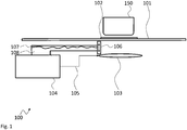
- Fig. 1 shows a block diagram of an embodiment of an induction cooker 100.
- the induction cooker 100 comprises a cooking surface 101 with an exemplary cooking hob 102. Under the cooking hob 102 the induction cooker 100 comprises a coil 103 and a cooking vessel 150 is shown on the cooking hob 102.
- a power electronics circuit 104 is coupled to the coil 103 via a power line 105. Further, the power electronics circuit 104 is coupled to a fluid conduction arrangement 107 that is filled with a fluid 108.
- the fluid conduction arrangement 107 is further coupled with a movement arrangement 106 for moving the coil up and down.
- the power electronics circuit 104 will drive the coil 103 with a high frequency current. In response to this driving current, the coil 103 will generate a magnetic field that will induce currents in the cooking vessel 150 and therefore heat up the cooking vessel 150. While driving the coil 103 with the high frequency current, the power electronics circuit 104, especially the switching elements of the power electronics circuit 104, will heat up.
- the degree of the temperature increase in the power electronics circuit 104 not only depends on the frequency of the high frequency current and the dimensions of the coil 103. Instead, the degree of the temperature increase will also depend on the ferromagnetic permeability of the cooking vessel 150. As explained above, with a cooking vessel 150 that has a very high ferromagnetic permeability, the power electronics circuit 104 will heat up more than with a cooking vessel 150 that has a low ferromagnetic permeability.
- the induction cooker 100 comprises the movement arrangement 106 that is driven by the volume change of the fluid 108.
- the fluid conduction arrangement 107 that is filled with the fluid 108 is thermally coupled to the power electronics circuit 104.
- the fluid conduction arrangement 107 is mechanically coupled to the movement arrangement 106 such that a volume of the fluid 108 controls the movement of the movement arrangement 106. This means, that with increasing volume of the fluid 108, the distance between the coil 103 and the cooking surface 101 will increase and vice versa.
- the fluid 108 may comprise a positive coefficient of expansion. It is understood, that an inverse mechanical arrangement may also be provided that works with a fluid 108 that has a negative coefficient of expansion.
- Fig. 2 shows a block diagram of another embodiment of an induction cooker 200.
- the induction cooker 200 is based on the induction cooker 100. Therefore, the induction cooker 200 also comprises a cooking surface 201 with an exemplary cooking hob 202. Under the cooking hob 202 the induction cooker 200 comprises a coil 203 and a cooking vessel 250 is shown on the cooking hob 202.
- a power electronics circuit 204 is coupled to the coil 203 via a power line 205. Further, the power electronics circuit 204 is coupled to a fluid conduction arrangement 207 that is filled with a fluid 208.
- the fluid conduction arrangement 207 is further coupled with a movement arrangement 206 for moving the coil up and down.
- the fluid conduction arrangement 207 comprises a heat transfer section 215 that is thermally coupled to the power electronics circuit 204 to maximize the heat transfer between the power electronics circuit 204 and the fluid conduction arrangement 207.
- the fluid conduction arrangement 207 comprises a fluid conduction section 214 that is on one end coupled to the heat transfer section 215 and on the other end coupled to the movement arrangement 206.
- the thermal conductivity of the heat transfer section 215 may be higher than a thermal conductivity of the fluid conduction section 214.
- the fluid conduction section 214 may e.g. be isolated or be made from another material than the heat transfer section 215.
- the fluid conduction section 214 may comprise a clear cross section that narrows from the heat transfer section to the movement arrangement 206.
- the fluid conduction arrangement 207 comprises a number of expandable elements 212, 213, here cylinders. It is understood, that e.g. flexible bladders may also be used.
- the expandable elements 212, 213 are coupled to the movement arrangement 206 such that the coil 203 moves away from the cooking surface 201 when the volume of the fluid 208 increases.
- the movement arrangement 206 comprises two springs 210, 211. It is understood, that the two springs 210, 211 are just exemplarily shown and that any other number of springs, e.g. three or more, may also be provided.
- the expandable elements 212, 213 are coupled to the springs 210, 211 such that they expand the springs 210, 211 when the volume of the fluid (108, 208) increases.
- Fig. 3 shows a flow diagram of an embodiment of a method for operating an induction cooker 100, 200.
- the method comprises operating S1 a power electronics circuit 104, 204 of the induction cooker 100, 200 for driving a coil 103, 203 of the induction cooker 100, 200 that is placed under a cooking surface 101, 201 of the induction cooker 100, 200 with a high frequency electric current, transferring S2 heat from the power electronics circuit 104, 204 to a fluid 108, 208 in a fluid conduction arrangement 107, 207 of the induction cooker 100, 200, and controlling S3 a movement arrangement 106, 206 for controllably moving the coil 103, 203 towards the cooking surface 101, 201 and away from the cooking surface 101, 201 based on a volume of the fluid 108, 208.
- fluid 108, 208 may comprise a positive coefficient of expansion.
- heat may e.g. be transferred to the fluid 108, 208 at a heat transfer section 215 of the fluid conduction arrangement 107, 207.
- a heat transfer section 215 may be thermally coupled to the power electronics circuit 104, 204 in order to maximize the heat transfer from e.g. a power electronics circuit of the induction cooker 100, 200 to the fluid 108, 208.
- a change of the volume of the fluid 108, 208 is transferred via a fluid conduction section 214 of the fluid conduction arrangement 107, 207 to the movement arrangement 106, 206.
- fluid conduction section 214 is on one end coupled to the heat transfer section 215 and on the other end coupled to the movement arrangement 106, 206.
- a change of the volume of the fluid 108, 208 may be transferred via a clear cross section of the fluid conduction section 214 that narrows from the heat transfer section 215 to the movement arrangement 106, 206.
- the fluid conduction section 214 may also split into more than one conduction pipes or elements.
- a thermal conductivity of the heat transfer section 215 may be higher than a thermal conductivity of the fluid conduction section 214.
- the movement arrangement 106, 206 may be controlled by a number of expandable elements 212, 213 of the fluid conduction arrangement 107, 207.
- Such expandable elements 212, 213 may be coupled to the movement arrangement 106, 206 such that the coil 103, 203 moves away from the cooking surface 101, 201 when the volume of the fluid 108, 208 increases.
- the expandable elements 212, 213 may e.g. expand a number of springs 210, 211 of the movement arrangement 106, 206 when the volume of the fluid 108, 208 increases.
- the present invention provides an induction cooker 100, 200 comprising a cooking surface 101, 201, a coil 103, 203 that is arranged under the cooking surface 101, 201, a power electronics circuit 104, 204 that is electrically coupled to the coil 103, 203 for driving the coil 103, 203 with a high frequency electric current, a movement arrangement 106, 206 that is coupled to the coil 103, 203 and that is configured to controllably move the coil 103, 203 towards the cooking surface 101, 201 and away from the cooking surface 101, 201, and a fluid conduction arrangement 107, 207 that is filled with a fluid 108, 208 and that is thermally coupled to the power electronics circuit 104, 204 and that is mechanically coupled to the movement arrangement 106, 206 such that a volume of the fluid 108, 208 controls the movement of the movement arrangement 106, 206. Further, the present invention provides a method for operating an induction cooker 100, 200.
Landscapes
- Physics & Mathematics (AREA)
- Electromagnetism (AREA)
- General Induction Heating (AREA)
Abstract
Description
- The invention relates to an induction cooker. Further, the invention relates to a method for operating an induction cooker.
- Although applicable to any cooking device, the present invention will mainly be described in conjunction with induction cookers.
- Induction cookers are cooking devices that transfer energy to cooking vessels via a magnetic field that is generated by switching current through a coil at a high frequency. The switching is usually performed with semiconductor switches that are controlled by PWM signals that are generated by a controller.
- The switched currents pass through the induction coil and change with time according to the switching frequency. As a consequence a magnetic field is generated by the coil. This magnetic field induces currents in a ferromagnetic cooking vessel that is placed on the induction cooker and therefore the cooking vessel heats up.
- Induction cookers are more power efficient than other types of cookers. However, the performance of the semiconductor switches varies according to the structure and material of the cooking vessel that is placed on the cooking hob over the coil during the switching operation. One relevant parameter that affects the performance and efficiency of the induction cooker is the temperature of the semiconductor switches at the time of switching.
- Usually, induction cookers are designed for cooking vessels of a typical or average ferromagnetic permeability. Therefore, with cooking vessels that have a ferromagnetic permeability that is higher than that of an average cooking vessel, more power will be transferred to the cooking vessel and the semiconductor switches will warm up above the normal operating temperature. In contrast, if the ferromagnetic permeability of the cooking vessel is lower than that of an average cooking vessel, less power will be transferred to the cooking vessel and the semiconductor switches will heat up less than under normal operating conditions.
- Accordingly, there is a need for improving the heat management of the switching elements in induction cookers.
- The above stated problem is solved by the features of the independent claims. It is understood, that independent claims of a claim category may be formed in analogy to the dependent claims of another claim category.
- Accordingly, it is provided:
- Induction cooker comprising a cooking surface, a coil that is arranged under the cooking surface, a power electronics circuit that is electrically coupled to the coil for driving the coil with a high frequency electric current, a movement arrangement that is coupled to the coil and that is configured to controllably move the coil towards the cooking surface and away from the cooking surface, and a fluid conduction arrangement that is filled with a fluid and that is thermally coupled to the power electronics circuit and that is mechanically coupled to the movement arrangement such that a volume of the fluid controls the movement of the movement arrangement.
- Further, it is provided:
- Method for operating an induction cooker according to any one of the preceding claims, the method comprising operating a power electronics circuit of the induction cooker for driving a coil of the induction cooker that is placed under a cooking surface of the induction cooker with a high frequency electric current, transferring heat from the power electronics circuit to a fluid in a fluid conduction arrangement of the induction cooker, and controlling a movement arrangement for controllably moving the coil towards the cooking surface and away from the cooking surface based on a volume of the fluid.
- The present invention is based on the finding that the distance between the coil and the cooking surface, may be adjusted in order to adapt the current that runs through the coil of the induction cooker and therefore in order to adapt the load on the power electronics circuit.
- For example, when a cooking vessel with a low or a high ferromagnetic permeability compared to an average cooking vessel is placed on the induction cooker, the distance between the cooking vessel's base and the coil may be adaptively changed in order to adapt the load on the power electronics circuit. The distance between the cooking vessel's base and the coil should be closer than for an average cooking vessel when the ferromagnetic permeability of the cooking vessel is lower than that of an average cooking vessel. Otherwise, the desired power values cannot be transferred to the pot by the coil. In contrast, if the ferromagnetic permeability of the cooking vessel is higher than that of an average cooking vessel, the distance between the coil and the base of the cooking vessel should be increased.
- To this end, the present invention provides the coil that is movably arranged under the cooking surface and coupled to the movement arrangement. It is understood, that the movement arrangement may at the same time serve to fix or hold the coil under the cooking surface, e.g. on guides or rails. The term "under the cooking surface" in this regard refers to the coil being arranged on the side of the cooking surface that is opposite to the side on which the cooking vessel is placed.
- The movement arrangement may comprise any type of element that is necessary to guide the coil and to perform the movement depending on the volume of the fluid. Further, the cooking surface will usually be placed in a horizontal plane. The movement towards and away from the cooking surface may therefore be a vertical movement.
- In the induction cooker, heat that is generated at the power electronics circuit will be transferred to the fluid. Consequently, when the temperature of the fluid increases, the volume of the fluid increases and vice versa. The change of the volume of the fluid is then transferred to the movement arrangement and will result in a movement of the coil away from or towards the cooking surface.
- With the help of the present invention, the position of the coil will therefore change by upwards and downwards movement that is caused by the volume change of the fluid. Therefore, no temperature sensors or electromechanical movement elements are necessary and a very simple construction is provided.
- It is understood, that the induction cooker may also comprise multiple hobs and therefore multiple coils. It is further understood, that the arrangement of the present invention may be provided for every single one of the hobs and coils.
- Further embodiments of the present invention are subject of the further subclaims and of the following description, referring to the drawings.
- In an embodiment, the fluid conduction arrangement may comprise a heat transfer section that is thermally coupled to the power electronics circuit.
- The heat transfer section is the section of the fluid conduction arrangement that is responsible for transferring heat from the power electronics circuit, especially power switches on the power electronics circuit, to the fluid in the fluid conduction arrangement. Therefore, the heat transfer section may e.g. comprise a material with a high thermal conductivity.
- In another embodiment, the fluid conduction arrangement may comprise a fluid conduction section that is on one end coupled to the heat transfer section and on the other end coupled to the movement arrangement.
- The fluid conduction section is the section that passes on the fluid to the movement arrangement when the volume of the fluid changes according to the heat that is transferred from the power electronics circuit to the fluid. Similar to a heat pipe, where the fluid is converted into vapor at the heat source and then transported to another section of the heat pipe, the fluid conduction arrangement heats up the fluid at the heat transfer section and transports the fluid to another section, i.e. the movement arrangement, where the fluid becomes effective in moving the coil into the desired position.
- "Moving" or "passing on" the fluid in this respect not necessarily refers to a pumping-like movement or flow of the fluid. Instead "moving" or "passing on" the fluid may also refer to a simple forwarding of the expansion of the fluid at the power electronics circuit to the movement arrangement.
- In a further embodiment, the fluid conduction section may comprise a clear cross section that narrows from the heat transfer section to the movement arrangement.
- By narrowing the clear cross section of the fluid conduction section from the heat transfer section to the movement arrangement, the amount of movement of the movement arrangement may be maximized, while the surface that is available for heat transfer to the fluid is maximized at the heat transfer section.
- In an embodiment, a thermal conductivity of the heat transfer section may be higher than a thermal conductivity of the fluid conduction section.
- By providing the heat transfer section with a higher thermal conductivity than the fluid conduction section, heat is mainly transferred to the fluid via the heat transfer section and not the fluid conduction section. Therefore, the dependence of the movement of the coil from the ambient temperature may be reduced and the temperature of the power electronics circuit will be the main parameter for the position of the coil.
- It is understood, that the thermal conductivity of the fluid conduction section may e.g. be reduced by isolating the fluid conduction section. This means, that the fluid conduction arrangement may e.g. be formed of a single component e.g. of copper and that the fluid conduction section may then be isolated separately.
- In another embodiment, the fluid conduction arrangement may comprise a number of expandable elements, i.e. one for every spring (see below), wherein the expandable elements may be coupled to the movement arrangement such that the coil moves away from the cooking surface when the volume of the fluid increases.
- The expandable elements may e.g. comprise flexible membranes or a kind of hydraulic cylinders with a moving piston that expand when the volume of the fluid increases due to an increase of the temperature of the fluid. The expandable elements may e.g. be provided on that end of the above mentioned fluid conduction section that is coupled to the movement arrangement. It is understood, that the fluid conduction section may split at some point into a dedicated fluid channel or pipe for every one of the expandable elements.
- The expandable elements may e.g. be directly coupled to the coil or a frame that supports the coil. Further, the expandable elements may e.g. be arranged between the cooking surface and the coil. Therefore, when the expandable elements expand, the coil will move away from the cooking surface, and when the expandable elements contract, the coil will move toward the cooking surface.
- In a further embodiment, the movement arrangement may comprise a number, i.e. one or more, of springs, and the expandable elements may be coupled to the springs such that they expand the springs when the volume of the fluid increases.
- It is understood, that a dedicated expandable element may be provided for every spring. However, as alternative every expandable element may actuate more than one spring or more than one expandable element may be provided per spring.
- If the expandable elements expand the springs when the volume of the fluid increases, the expandable elements will accordingly reduce the pressure on the springs and allow the springs to contract when the volume of the fluid decreases.
- In an exemplary embodiment, three expandable elements may be provided that are coupled to the coil, a respective frame or the springs such that the coil is held in a steady position.
- The term "spring" in this context refers to any type of flexible element that comprises a resting position or normal position and that when moved out of this resting position provides a return force that acts to return the flexible element into its resting position. Such a flexible element may also comprise a plurality of movably interrelated elements.
- In another embodiment, the fluid may comprise a positive coefficient of expansion, e.g. a positive volumetric coefficient of expansion.
- The selection of the fluid depends on the specific dimensions of the induction cooker, especially the operating temperature range of the power electronics circuit and the required range of movement of the movement arrangement.
- The fluid may be selected such that with the maximum temperature of the power electronics circuit, the expansion of the fluid is large enough to move the movement arrangement to the end position with the maximum distance between the coil and the cooking surface. Consequently, with the minimum temperature of the power electronics circuit, the movement arrangement may move to the other end position with the minimum distance between the coil and the cooking surface.
- The following list is a non-exhaustive list of possible fluids and their respective expansion coefficients:
Liquid Volumetric Coefficient of Expansion (1/K, 1/°C) (1/°F) Acetic acid 0.00110 0.00061 Acetone 0.00143 0.00079 Alcohol, ethyl (ethanol) 0.00109 0.00061 Alcohol, methyl (methanol,wood alcohol, wood naphtha, wood spirits, CH3OH) 0.00149 0.00083 Ammonia 0.00245 0.00136 Aniline 0.00085 0.00047 Benzene 0.00125 0.00069 Bromine 0.00110 0.00061 Calcium Chloride, 5.8% solution 0.00025 Calcium Chloride, 40.9% solution 0.00046 Carbon disulfide 0.00119 0.00066 Carbon tetrachloride 0.00122 0.00068 Chloroform 0.00127 0.00071 Ether 0.00160 0.00089 Ethyl acetate 0.00138 0.00077 Ethylene glycol 0.00057 0.00032 Dichlorodifluoromethane refrigerant R-12 0.0026 0.00144 n-Heptane 0.00124 0.00069 Hydrochloric acid, 33.2% solution 0.00046 Isobutyl alcohol 0.00094 0.00052 Gasoline 0.00095 0.00053 Glycerine (glycerol) 0.00050 0.00028 Kerosene, jet fuel 0.00099 0.00055 Mercury 0.00018 0.00010 Methyl iodide 0.0012 0.00067 n-Octane 0.00114 0.00063 Oil (unused engine oil) 0.00070 0.00039 Olive oil 0.00070 Paraffin oil 0.000764 0.00042 Petroleum 0.0010 0.00056 n-Pentane 0.00158 0.00088 Phenol 0.0009 0.00050 Potassium chloride, 24.3% solutiuon 0.00035 Sodium chloride, 20.6% solution 0.00041 Sodium sulfate, 24% solution 0.00041 Sulfuric acid, concentrated 0.00055 0.00031 Toluene 0.00108 0.00060 Trichloroethylene 0.001170 0.00065 Turpentine 0.001000 0.00056 Water 0.000214 0.00012 - For a more complete understanding of the present invention and advantages thereof, reference is now made to the following description taken in conjunction with the accompanying drawings. The invention is explained in more detail below using exemplary embodiments which are specified in the schematic figures of the drawings, in which:
- Fig. 1
- shows a block diagram of an embodiment of an induction cooker according to the present invention;
- Fig. 2
- shows a block diagram of another embodiment of an induction cooker according to the present invention; and
- Fig. 3
- shows a flow diagram of an embodiment of a method according to the present invention.
- In the figures like reference signs denote like elements unless stated otherwise.
-
Fig. 1 shows a block diagram of an embodiment of aninduction cooker 100. Theinduction cooker 100 comprises acooking surface 101 with anexemplary cooking hob 102. Under thecooking hob 102 theinduction cooker 100 comprises acoil 103 and acooking vessel 150 is shown on thecooking hob 102. Apower electronics circuit 104 is coupled to thecoil 103 via apower line 105. Further, thepower electronics circuit 104 is coupled to afluid conduction arrangement 107 that is filled with afluid 108. Thefluid conduction arrangement 107 is further coupled with amovement arrangement 106 for moving the coil up and down. - During operation of the
induction cooker 100, thepower electronics circuit 104 will drive thecoil 103 with a high frequency current. In response to this driving current, thecoil 103 will generate a magnetic field that will induce currents in thecooking vessel 150 and therefore heat up thecooking vessel 150. While driving thecoil 103 with the high frequency current, thepower electronics circuit 104, especially the switching elements of thepower electronics circuit 104, will heat up. The degree of the temperature increase in thepower electronics circuit 104 not only depends on the frequency of the high frequency current and the dimensions of thecoil 103. Instead, the degree of the temperature increase will also depend on the ferromagnetic permeability of thecooking vessel 150. As explained above, with acooking vessel 150 that has a very high ferromagnetic permeability, thepower electronics circuit 104 will heat up more than with acooking vessel 150 that has a low ferromagnetic permeability. - To adjust the energy transfer between the
coil 103 and thecooking vessel 150, and therefore the temperature increase in thepower electronics circuit 104, theinduction cooker 100 comprises themovement arrangement 106 that is driven by the volume change of thefluid 108. - To this end, the
fluid conduction arrangement 107 that is filled with the fluid 108 is thermally coupled to thepower electronics circuit 104. In addition, thefluid conduction arrangement 107 is mechanically coupled to themovement arrangement 106 such that a volume of the fluid 108 controls the movement of themovement arrangement 106. This means, that with increasing volume of the fluid 108, the distance between thecoil 103 and thecooking surface 101 will increase and vice versa. - To this end, the fluid 108 may comprise a positive coefficient of expansion. It is understood, that an inverse mechanical arrangement may also be provided that works with a fluid 108 that has a negative coefficient of expansion.
-
Fig. 2 shows a block diagram of another embodiment of aninduction cooker 200. Theinduction cooker 200 is based on theinduction cooker 100. Therefore, theinduction cooker 200 also comprises acooking surface 201 with anexemplary cooking hob 202. Under thecooking hob 202 theinduction cooker 200 comprises acoil 203 and acooking vessel 250 is shown on thecooking hob 202. Apower electronics circuit 204 is coupled to thecoil 203 via apower line 205. Further, thepower electronics circuit 204 is coupled to afluid conduction arrangement 207 that is filled with afluid 208. Thefluid conduction arrangement 207 is further coupled with amovement arrangement 206 for moving the coil up and down. - The
fluid conduction arrangement 207 comprises aheat transfer section 215 that is thermally coupled to thepower electronics circuit 204 to maximize the heat transfer between thepower electronics circuit 204 and thefluid conduction arrangement 207. - Further, the
fluid conduction arrangement 207 comprises afluid conduction section 214 that is on one end coupled to theheat transfer section 215 and on the other end coupled to themovement arrangement 206. The thermal conductivity of theheat transfer section 215 may be higher than a thermal conductivity of thefluid conduction section 214. To this end, thefluid conduction section 214 may e.g. be isolated or be made from another material than theheat transfer section 215. - In addition or as alternative, the
fluid conduction section 214 may comprise a clear cross section that narrows from the heat transfer section to themovement arrangement 206. - The
fluid conduction arrangement 207 comprises a number ofexpandable elements expandable elements movement arrangement 206 such that thecoil 203 moves away from thecooking surface 201 when the volume of the fluid 208 increases. To this end, themovement arrangement 206 comprises twosprings springs - The
expandable elements springs springs - In
Fig. 2 it becomes clear that an expansion of the fluid 208 will lead to an expansion of thecylinders coil 103 away from thecooking surface 201, and vice versa. - For sake of clarity in the following description of the method based
Fig. 3 the reference signs used above in the description of apparatus basedFigs. 1 - 2 will be maintained. -
Fig. 3 shows a flow diagram of an embodiment of a method for operating aninduction cooker - The method comprises operating S1 a
power electronics circuit induction cooker coil induction cooker cooking surface induction cooker power electronics circuit fluid conduction arrangement induction cooker movement arrangement coil cooking surface cooking surface - It is understood, that the fluid 108, 208 may comprise a positive coefficient of expansion.
- According to the method of the present invention heat may e.g. be transferred to the fluid 108, 208 at a
heat transfer section 215 of thefluid conduction arrangement heat transfer section 215 may be thermally coupled to thepower electronics circuit induction cooker - A change of the volume of the fluid 108, 208 is transferred via a
fluid conduction section 214 of thefluid conduction arrangement movement arrangement fluid conduction section 214 is on one end coupled to theheat transfer section 215 and on the other end coupled to themovement arrangement - In addition, a change of the volume of the fluid 108, 208 may be transferred via a clear cross section of the
fluid conduction section 214 that narrows from theheat transfer section 215 to themovement arrangement fluid conduction section 214 may also split into more than one conduction pipes or elements. - Further, a thermal conductivity of the
heat transfer section 215 may be higher than a thermal conductivity of thefluid conduction section 214. - The
movement arrangement expandable elements fluid conduction arrangement expandable elements movement arrangement coil cooking surface - The
expandable elements springs movement arrangement - Although specific embodiments have been illustrated and described herein, it will be appreciated by those of ordinary skill in the art that a variety of alternate and/or equivalent implementations exist. It should be appreciated that the exemplary embodiment or exemplary embodiments are only examples, and are not intended to limit the scope, applicability, or configuration in any way. Rather, the foregoing summary and detailed description will provide those skilled in the art with a convenient road map for implementing at least one exemplary embodiment, it being understood that various changes may be made in the function and arrangement of elements described in an exemplary embodiment without departing from the scope as set forth in the appended claims and their legal equivalents. Generally, this application is intended to cover any adaptations or variations of the specific embodiments discussed herein.
- The present invention provides an
induction cooker cooking surface coil cooking surface power electronics circuit coil coil movement arrangement coil coil cooking surface cooking surface fluid conduction arrangement power electronics circuit movement arrangement movement arrangement induction cooker -
- 100, 200
- induction cooker
- 101, 201
- cooking surface
- 102, 202
- hob
- 103, 203
- coil
- 104, 204
- power electronics circuit
- 105, 205
- power line
- 106, 206
- movement arrangement
- 107, 207
- fluid conduction arrangement
- 108, 208
- fluid
- 210, 211
- spring
- 212, 213
- cylinder
- 214
- fluid conduction section
- 215
- heat transfer section
- 150, 250
- cooking vessel
- S1, S2, S3
- method steps
Claims (15)
- Induction cooker (100, 200) comprising:a cooking surface (101, 201),a coil (103, 203) that is arranged under the cooking surface (101, 201),a power electronics circuit (104, 204) that is electrically coupled to the coil (103, 203) for driving the coil (103, 203) with a high frequency electric current,a movement arrangement (106, 206) that is coupled to the coil (103, 203) and that is configured to controllably move the coil (103, 203) towards the cooking surface (101, 201) and away from the cooking surface (101, 201), anda fluid conduction arrangement (107, 207) that is filled with a fluid (108, 208) and that is thermally coupled to the power electronics circuit (104, 204) and that is mechanically coupled to the movement arrangement (106, 206) such that a volume of the fluid (108, 208) controls the movement of the movement arrangement (106, 206).
- Induction cooker (100, 200) according to claim 1, wherein the fluid conduction arrangement (107, 207) comprises a heat transfer section (215) that is thermally coupled to the power electronics circuit (104, 204).
- Induction cooker (100, 200) according to claim 2, wherein the fluid conduction arrangement (107, 207) comprises a fluid conduction section (214) that is on one end coupled to the heat transfer section (215) and on the other end coupled to the movement arrangement (106, 206).
- Induction cooker (100, 200) according to claim 3, wherein the fluid conduction section (214) comprises a clear cross section that narrows from the heat transfer section (215) to the movement arrangement (106, 206).
- Induction cooker (100, 200) according to any one of claims 3 and 4, wherein a thermal conductivity of the heat transfer section (215) is higher than a thermal conductivity of the fluid conduction section (214).
- Induction cooker (100, 200) according to any one of the preceding claims, wherein the fluid conduction arrangement (107, 207) comprises a number of expandable elements (212, 213), wherein the expandable elements (212, 213) are coupled to the movement arrangement (106, 206) such that the coil (103, 203) moves away from the cooking surface (101, 201) when the volume of the fluid (108, 208) increases.
- Induction cooker (100, 200) according to claim 6, wherein the movement arrangement (106, 206) comprises a number of springs (210, 211), and wherein the expandable elements (212, 213) are coupled to the springs (210, 211) such that they expand the springs (210, 211) when the volume of the fluid (108, 208) increases.
- Induction cooker (100, 200) according to any one of the preceding claims, wherein the fluid (108, 208) comprises a positive coefficient of expansion.
- Method for operating an induction cooker (100, 200) according to any one of the preceding claims, the method comprising:operating (S1) a power electronics circuit (104, 204) of the induction cooker (100, 200) for driving a coil (103, 203) of the induction cooker (100, 200) that is placed under a cooking surface (101, 201) of the induction cooker (100, 200) with a high frequency electric current,transferring (S2) heat from the power electronics circuit (104, 204) to a fluid (108, 208) in a fluid conduction arrangement (107, 207) of the induction cooker (100, 200), andcontrolling (S3) a movement arrangement (106, 206) for controllably moving the coil (103, 203) towards the cooking surface (101, 201) and away from the cooking surface (101, 201) based on a volume of the fluid (108, 208).
- Method according to claim 9, wherein the heat is transferred to the fluid (108, 208) at a heat transfer section (215) of the fluid conduction arrangement (107, 207), and wherein the heat transfer section (215) is thermally coupled to the power electronics circuit (104, 204).
- Method according to claim 10, wherein a change of the volume of the fluid (108, 208) is transferred via a fluid conduction section (214) of the fluid conduction arrangement (107, 207), wherein the fluid conduction section (214) is on one end coupled to the heat transfer section (215) and on the other end coupled to the movement arrangement (106, 206).
- Method according to claim 11, wherein a change of the volume of the fluid (108, 208) is transferred via a clear cross section of the fluid conduction section (214) that narrows from the heat transfer section (215) to the movement arrangement (106, 206); and/or
wherein a thermal conductivity of the heat transfer section (215) is higher than a thermal conductivity of the fluid conduction section (214). - Method according to any one of the preceding claims 9 to 13, wherein the movement arrangement (106, 206) is controlled by a number of expandable elements (212, 213) of the fluid conduction arrangement (107, 207), wherein the expandable elements (212, 213) are coupled to the movement arrangement (106, 206) such that the coil (103, 203) moves away from the cooking surface (101, 201) when the volume of the fluid (108, 208) increases.
- Method according to claim 13, wherein the expandable elements (212, 213) expand a number of springs (210, 211) of the movement arrangement (106, 206) when the volume of the fluid (108, 208) increases.
- Method according to any one of the preceding claims 9 to 14, wherein the fluid (108, 208) comprises a positive coefficient of expansion.
Priority Applications (1)
| Application Number | Priority Date | Filing Date | Title |
|---|---|---|---|
| EP18161960.2A EP3541145B1 (en) | 2018-03-15 | 2018-03-15 | Induction cooker, and method for operating an induction cooker |
Applications Claiming Priority (1)
| Application Number | Priority Date | Filing Date | Title |
|---|---|---|---|
| EP18161960.2A EP3541145B1 (en) | 2018-03-15 | 2018-03-15 | Induction cooker, and method for operating an induction cooker |
Publications (2)
| Publication Number | Publication Date |
|---|---|
| EP3541145A1 true EP3541145A1 (en) | 2019-09-18 |
| EP3541145B1 EP3541145B1 (en) | 2020-09-30 |
Family
ID=61683639
Family Applications (1)
| Application Number | Title | Priority Date | Filing Date |
|---|---|---|---|
| EP18161960.2A Active EP3541145B1 (en) | 2018-03-15 | 2018-03-15 | Induction cooker, and method for operating an induction cooker |
Country Status (1)
| Country | Link |
|---|---|
| EP (1) | EP3541145B1 (en) |
Citations (5)
| Publication number | Priority date | Publication date | Assignee | Title |
|---|---|---|---|---|
| FR2261607A1 (en) * | 1973-09-28 | 1975-09-12 | Matsushita Electric Industrial Co Ltd | |
| JPH0233884A (en) * | 1988-07-21 | 1990-02-05 | Fuji Electric Co Ltd | Induction heating apparatus of electro-magnetic cooker |
| CN202475823U (en) * | 2011-12-08 | 2012-10-03 | 九阳股份有限公司 | Liquid cooling heat dissipation electromagnetic heating wire coil and induction cooker |
| EP3048861A1 (en) * | 2015-01-21 | 2016-07-27 | FLUXRON Solutions AG | Induction heating device |
| CN206609008U (en) * | 2017-02-23 | 2017-11-03 | 九阳股份有限公司 | A kind of liquid-cooling heat radiation electromagnetic oven |
-
2018
- 2018-03-15 EP EP18161960.2A patent/EP3541145B1/en active Active
Patent Citations (5)
| Publication number | Priority date | Publication date | Assignee | Title |
|---|---|---|---|---|
| FR2261607A1 (en) * | 1973-09-28 | 1975-09-12 | Matsushita Electric Industrial Co Ltd | |
| JPH0233884A (en) * | 1988-07-21 | 1990-02-05 | Fuji Electric Co Ltd | Induction heating apparatus of electro-magnetic cooker |
| CN202475823U (en) * | 2011-12-08 | 2012-10-03 | 九阳股份有限公司 | Liquid cooling heat dissipation electromagnetic heating wire coil and induction cooker |
| EP3048861A1 (en) * | 2015-01-21 | 2016-07-27 | FLUXRON Solutions AG | Induction heating device |
| CN206609008U (en) * | 2017-02-23 | 2017-11-03 | 九阳股份有限公司 | A kind of liquid-cooling heat radiation electromagnetic oven |
Also Published As
| Publication number | Publication date |
|---|---|
| EP3541145B1 (en) | 2020-09-30 |
Similar Documents
| Publication | Publication Date | Title |
|---|---|---|
| EP1112506B1 (en) | Temperature control system for a permanent magnet system | |
| EP2281312A1 (en) | Scalable dense pv solar receiver for high concentration | |
| US3261905A (en) | Stationary induction apparatus cooling system | |
| US11212931B2 (en) | Subsea installation | |
| JP2002208538A (en) | Liquid variable condenser | |
| CN112290802A (en) | An ultra-wide gain range adjustment method for L-LLC resonant converter | |
| EP3541145B1 (en) | Induction cooker, and method for operating an induction cooker | |
| CN118919231A (en) | Self-adaptive oil immersed transformer heat abstractor | |
| EP2853682A1 (en) | Subsea enclosure system for disposal of generated heat | |
| CN118591165B (en) | Coal cutter electric cabinet with cooling water channel | |
| JPH08138928A (en) | Permanent current switch | |
| EP3939384B1 (en) | Induction cooking device and method | |
| CN112151266B (en) | Device and method for reducing capacitor temperature coefficient | |
| US20070107453A1 (en) | Heat exchanger with embedded heater | |
| CN109662561B (en) | Molecular resonance electric cooker | |
| CN217178911U (en) | Pipeline type heating device for oil and gas transportation | |
| CN103115441A (en) | Dome type focusing heat accumulator and dome type solar thermoelectric system | |
| CN104053261A (en) | Coil disc assembly and electromagnetic induction heating device | |
| JP5033020B2 (en) | Heat treatment method using induction heating and induction heating apparatus | |
| EP3720245B1 (en) | Induction cooking device and method | |
| CN117995524B (en) | Intelligent regulation and control magnetic flux transformer | |
| CN209911842U (en) | Temperature-adjustable temperature controller | |
| CN214704430U (en) | Flow control device | |
| EP2565554A1 (en) | Thermal collector and PVT collector | |
| JP2006014486A (en) | Electric motor cooling device |
Legal Events
| Date | Code | Title | Description |
|---|---|---|---|
| PUAI | Public reference made under article 153(3) epc to a published international application that has entered the european phase |
Free format text: ORIGINAL CODE: 0009012 |
|
| STAA | Information on the status of an ep patent application or granted ep patent |
Free format text: STATUS: THE APPLICATION HAS BEEN PUBLISHED |
|
| AK | Designated contracting states |
Kind code of ref document: A1 Designated state(s): AL AT BE BG CH CY CZ DE DK EE ES FI FR GB GR HR HU IE IS IT LI LT LU LV MC MK MT NL NO PL PT RO RS SE SI SK SM TR |
|
| AX | Request for extension of the european patent |
Extension state: BA ME |
|
| STAA | Information on the status of an ep patent application or granted ep patent |
Free format text: STATUS: REQUEST FOR EXAMINATION WAS MADE |
|
| 17P | Request for examination filed |
Effective date: 20200304 |
|
| RBV | Designated contracting states (corrected) |
Designated state(s): AL AT BE BG CH CY CZ DE DK EE ES FI FR GB GR HR HU IE IS IT LI LT LU LV MC MK MT NL NO PL PT RO RS SE SI SK SM TR |
|
| GRAP | Despatch of communication of intention to grant a patent |
Free format text: ORIGINAL CODE: EPIDOSNIGR1 |
|
| STAA | Information on the status of an ep patent application or granted ep patent |
Free format text: STATUS: GRANT OF PATENT IS INTENDED |
|
| RIC1 | Information provided on ipc code assigned before grant |
Ipc: H05B 6/12 20060101AFI20200414BHEP Ipc: F24C 15/10 20060101ALI20200414BHEP |
|
| INTG | Intention to grant announced |
Effective date: 20200429 |
|
| GRAS | Grant fee paid |
Free format text: ORIGINAL CODE: EPIDOSNIGR3 |
|
| GRAA | (expected) grant |
Free format text: ORIGINAL CODE: 0009210 |
|
| STAA | Information on the status of an ep patent application or granted ep patent |
Free format text: STATUS: THE PATENT HAS BEEN GRANTED |
|
| AK | Designated contracting states |
Kind code of ref document: B1 Designated state(s): AL AT BE BG CH CY CZ DE DK EE ES FI FR GB GR HR HU IE IS IT LI LT LU LV MC MK MT NL NO PL PT RO RS SE SI SK SM TR |
|
| REG | Reference to a national code |
Ref country code: CH Ref legal event code: EP Ref country code: GB Ref legal event code: FG4D |
|
| REG | Reference to a national code |
Ref country code: AT Ref legal event code: REF Ref document number: 1320142 Country of ref document: AT Kind code of ref document: T Effective date: 20201015 |
|
| REG | Reference to a national code |
Ref country code: DE Ref legal event code: R096 Ref document number: 602018008186 Country of ref document: DE |
|
| REG | Reference to a national code |
Ref country code: IE Ref legal event code: FG4D |
|
| PG25 | Lapsed in a contracting state [announced via postgrant information from national office to epo] |
Ref country code: HR Free format text: LAPSE BECAUSE OF FAILURE TO SUBMIT A TRANSLATION OF THE DESCRIPTION OR TO PAY THE FEE WITHIN THE PRESCRIBED TIME-LIMIT Effective date: 20200930 Ref country code: BG Free format text: LAPSE BECAUSE OF FAILURE TO SUBMIT A TRANSLATION OF THE DESCRIPTION OR TO PAY THE FEE WITHIN THE PRESCRIBED TIME-LIMIT Effective date: 20201230 Ref country code: SE Free format text: LAPSE BECAUSE OF FAILURE TO SUBMIT A TRANSLATION OF THE DESCRIPTION OR TO PAY THE FEE WITHIN THE PRESCRIBED TIME-LIMIT Effective date: 20200930 Ref country code: NO Free format text: LAPSE BECAUSE OF FAILURE TO SUBMIT A TRANSLATION OF THE DESCRIPTION OR TO PAY THE FEE WITHIN THE PRESCRIBED TIME-LIMIT Effective date: 20201230 Ref country code: FI Free format text: LAPSE BECAUSE OF FAILURE TO SUBMIT A TRANSLATION OF THE DESCRIPTION OR TO PAY THE FEE WITHIN THE PRESCRIBED TIME-LIMIT Effective date: 20200930 Ref country code: GR Free format text: LAPSE BECAUSE OF FAILURE TO SUBMIT A TRANSLATION OF THE DESCRIPTION OR TO PAY THE FEE WITHIN THE PRESCRIBED TIME-LIMIT Effective date: 20201231 |
|
| REG | Reference to a national code |
Ref country code: AT Ref legal event code: MK05 Ref document number: 1320142 Country of ref document: AT Kind code of ref document: T Effective date: 20200930 |
|
| PG25 | Lapsed in a contracting state [announced via postgrant information from national office to epo] |
Ref country code: RS Free format text: LAPSE BECAUSE OF FAILURE TO SUBMIT A TRANSLATION OF THE DESCRIPTION OR TO PAY THE FEE WITHIN THE PRESCRIBED TIME-LIMIT Effective date: 20200930 Ref country code: LV Free format text: LAPSE BECAUSE OF FAILURE TO SUBMIT A TRANSLATION OF THE DESCRIPTION OR TO PAY THE FEE WITHIN THE PRESCRIBED TIME-LIMIT Effective date: 20200930 |
|
| REG | Reference to a national code |
Ref country code: NL Ref legal event code: MP Effective date: 20200930 |
|
| REG | Reference to a national code |
Ref country code: LT Ref legal event code: MG4D |
|
| PG25 | Lapsed in a contracting state [announced via postgrant information from national office to epo] |
Ref country code: SM Free format text: LAPSE BECAUSE OF FAILURE TO SUBMIT A TRANSLATION OF THE DESCRIPTION OR TO PAY THE FEE WITHIN THE PRESCRIBED TIME-LIMIT Effective date: 20200930 Ref country code: LT Free format text: LAPSE BECAUSE OF FAILURE TO SUBMIT A TRANSLATION OF THE DESCRIPTION OR TO PAY THE FEE WITHIN THE PRESCRIBED TIME-LIMIT Effective date: 20200930 Ref country code: CZ Free format text: LAPSE BECAUSE OF FAILURE TO SUBMIT A TRANSLATION OF THE DESCRIPTION OR TO PAY THE FEE WITHIN THE PRESCRIBED TIME-LIMIT Effective date: 20200930 Ref country code: RO Free format text: LAPSE BECAUSE OF FAILURE TO SUBMIT A TRANSLATION OF THE DESCRIPTION OR TO PAY THE FEE WITHIN THE PRESCRIBED TIME-LIMIT Effective date: 20200930 Ref country code: PT Free format text: LAPSE BECAUSE OF FAILURE TO SUBMIT A TRANSLATION OF THE DESCRIPTION OR TO PAY THE FEE WITHIN THE PRESCRIBED TIME-LIMIT Effective date: 20210201 Ref country code: EE Free format text: LAPSE BECAUSE OF FAILURE TO SUBMIT A TRANSLATION OF THE DESCRIPTION OR TO PAY THE FEE WITHIN THE PRESCRIBED TIME-LIMIT Effective date: 20200930 |
|
| PG25 | Lapsed in a contracting state [announced via postgrant information from national office to epo] |
Ref country code: PL Free format text: LAPSE BECAUSE OF FAILURE TO SUBMIT A TRANSLATION OF THE DESCRIPTION OR TO PAY THE FEE WITHIN THE PRESCRIBED TIME-LIMIT Effective date: 20200930 Ref country code: IS Free format text: LAPSE BECAUSE OF FAILURE TO SUBMIT A TRANSLATION OF THE DESCRIPTION OR TO PAY THE FEE WITHIN THE PRESCRIBED TIME-LIMIT Effective date: 20210130 Ref country code: ES Free format text: LAPSE BECAUSE OF FAILURE TO SUBMIT A TRANSLATION OF THE DESCRIPTION OR TO PAY THE FEE WITHIN THE PRESCRIBED TIME-LIMIT Effective date: 20200930 Ref country code: AT Free format text: LAPSE BECAUSE OF FAILURE TO SUBMIT A TRANSLATION OF THE DESCRIPTION OR TO PAY THE FEE WITHIN THE PRESCRIBED TIME-LIMIT Effective date: 20200930 Ref country code: AL Free format text: LAPSE BECAUSE OF FAILURE TO SUBMIT A TRANSLATION OF THE DESCRIPTION OR TO PAY THE FEE WITHIN THE PRESCRIBED TIME-LIMIT Effective date: 20200930 |
|
| PG25 | Lapsed in a contracting state [announced via postgrant information from national office to epo] |
Ref country code: SK Free format text: LAPSE BECAUSE OF FAILURE TO SUBMIT A TRANSLATION OF THE DESCRIPTION OR TO PAY THE FEE WITHIN THE PRESCRIBED TIME-LIMIT Effective date: 20200930 Ref country code: NL Free format text: LAPSE BECAUSE OF FAILURE TO SUBMIT A TRANSLATION OF THE DESCRIPTION OR TO PAY THE FEE WITHIN THE PRESCRIBED TIME-LIMIT Effective date: 20200930 |
|
| REG | Reference to a national code |
Ref country code: DE Ref legal event code: R097 Ref document number: 602018008186 Country of ref document: DE |
|
| PLBE | No opposition filed within time limit |
Free format text: ORIGINAL CODE: 0009261 |
|
| STAA | Information on the status of an ep patent application or granted ep patent |
Free format text: STATUS: NO OPPOSITION FILED WITHIN TIME LIMIT |
|
| PG25 | Lapsed in a contracting state [announced via postgrant information from national office to epo] |
Ref country code: DK Free format text: LAPSE BECAUSE OF FAILURE TO SUBMIT A TRANSLATION OF THE DESCRIPTION OR TO PAY THE FEE WITHIN THE PRESCRIBED TIME-LIMIT Effective date: 20200930 |
|
| 26N | No opposition filed |
Effective date: 20210701 |
|
| REG | Reference to a national code |
Ref country code: DE Ref legal event code: R119 Ref document number: 602018008186 Country of ref document: DE |
|
| PG25 | Lapsed in a contracting state [announced via postgrant information from national office to epo] |
Ref country code: MC Free format text: LAPSE BECAUSE OF FAILURE TO SUBMIT A TRANSLATION OF THE DESCRIPTION OR TO PAY THE FEE WITHIN THE PRESCRIBED TIME-LIMIT Effective date: 20200930 Ref country code: IT Free format text: LAPSE BECAUSE OF FAILURE TO SUBMIT A TRANSLATION OF THE DESCRIPTION OR TO PAY THE FEE WITHIN THE PRESCRIBED TIME-LIMIT Effective date: 20200930 |
|
| REG | Reference to a national code |
Ref country code: CH Ref legal event code: PL |
|
| PG25 | Lapsed in a contracting state [announced via postgrant information from national office to epo] |
Ref country code: SI Free format text: LAPSE BECAUSE OF FAILURE TO SUBMIT A TRANSLATION OF THE DESCRIPTION OR TO PAY THE FEE WITHIN THE PRESCRIBED TIME-LIMIT Effective date: 20200930 |
|
| REG | Reference to a national code |
Ref country code: BE Ref legal event code: MM Effective date: 20210331 |
|
| PG25 | Lapsed in a contracting state [announced via postgrant information from national office to epo] |
Ref country code: FR Free format text: LAPSE BECAUSE OF NON-PAYMENT OF DUE FEES Effective date: 20210331 Ref country code: DE Free format text: LAPSE BECAUSE OF NON-PAYMENT OF DUE FEES Effective date: 20211001 Ref country code: CH Free format text: LAPSE BECAUSE OF NON-PAYMENT OF DUE FEES Effective date: 20210331 Ref country code: IE Free format text: LAPSE BECAUSE OF NON-PAYMENT OF DUE FEES Effective date: 20210315 Ref country code: LU Free format text: LAPSE BECAUSE OF NON-PAYMENT OF DUE FEES Effective date: 20210315 Ref country code: LI Free format text: LAPSE BECAUSE OF NON-PAYMENT OF DUE FEES Effective date: 20210331 |
|
| PG25 | Lapsed in a contracting state [announced via postgrant information from national office to epo] |
Ref country code: IS Free format text: LAPSE BECAUSE OF FAILURE TO SUBMIT A TRANSLATION OF THE DESCRIPTION OR TO PAY THE FEE WITHIN THE PRESCRIBED TIME-LIMIT Effective date: 20210130 |
|
| PG25 | Lapsed in a contracting state [announced via postgrant information from national office to epo] |
Ref country code: BE Free format text: LAPSE BECAUSE OF NON-PAYMENT OF DUE FEES Effective date: 20210331 |
|
| GBPC | Gb: european patent ceased through non-payment of renewal fee |
Effective date: 20220315 |
|
| PG25 | Lapsed in a contracting state [announced via postgrant information from national office to epo] |
Ref country code: GB Free format text: LAPSE BECAUSE OF NON-PAYMENT OF DUE FEES Effective date: 20220315 |
|
| PG25 | Lapsed in a contracting state [announced via postgrant information from national office to epo] |
Ref country code: CY Free format text: LAPSE BECAUSE OF FAILURE TO SUBMIT A TRANSLATION OF THE DESCRIPTION OR TO PAY THE FEE WITHIN THE PRESCRIBED TIME-LIMIT Effective date: 20200930 |
|
| PG25 | Lapsed in a contracting state [announced via postgrant information from national office to epo] |
Ref country code: HU Free format text: LAPSE BECAUSE OF FAILURE TO SUBMIT A TRANSLATION OF THE DESCRIPTION OR TO PAY THE FEE WITHIN THE PRESCRIBED TIME-LIMIT; INVALID AB INITIO Effective date: 20180315 |
|
| PG25 | Lapsed in a contracting state [announced via postgrant information from national office to epo] |
Ref country code: MK Free format text: LAPSE BECAUSE OF FAILURE TO SUBMIT A TRANSLATION OF THE DESCRIPTION OR TO PAY THE FEE WITHIN THE PRESCRIBED TIME-LIMIT Effective date: 20200930 |
|
| PG25 | Lapsed in a contracting state [announced via postgrant information from national office to epo] |
Ref country code: MT Free format text: LAPSE BECAUSE OF FAILURE TO SUBMIT A TRANSLATION OF THE DESCRIPTION OR TO PAY THE FEE WITHIN THE PRESCRIBED TIME-LIMIT Effective date: 20200930 |
|
| PGFP | Annual fee paid to national office [announced via postgrant information from national office to epo] |
Ref country code: TR Payment date: 20260313 Year of fee payment: 9 |