EP3541085A1 - Sensor management device, sensor information synchronization method, control program, and recording medium - Google Patents
Sensor management device, sensor information synchronization method, control program, and recording medium Download PDFInfo
- Publication number
- EP3541085A1 EP3541085A1 EP19156689.2A EP19156689A EP3541085A1 EP 3541085 A1 EP3541085 A1 EP 3541085A1 EP 19156689 A EP19156689 A EP 19156689A EP 3541085 A1 EP3541085 A1 EP 3541085A1
- Authority
- EP
- European Patent Office
- Prior art keywords
- sensor information
- tag
- wireless sensors
- sensor
- acquisition start
- Prior art date
- Legal status (The legal status is an assumption and is not a legal conclusion. Google has not performed a legal analysis and makes no representation as to the accuracy of the status listed.)
- Granted
Links
Images



Classifications
-
- H—ELECTRICITY
- H04—ELECTRIC COMMUNICATION TECHNIQUE
- H04Q—SELECTING
- H04Q9/00—Arrangements in telecontrol or telemetry systems for selectively calling a substation from a main station, in which substation desired apparatus is selected for applying a control signal thereto or for obtaining measured values therefrom
-
- G—PHYSICS
- G06—COMPUTING OR CALCULATING; COUNTING
- G06K—GRAPHICAL DATA READING; PRESENTATION OF DATA; RECORD CARRIERS; HANDLING RECORD CARRIERS
- G06K7/00—Methods or arrangements for sensing record carriers, e.g. for reading patterns
- G06K7/10—Methods or arrangements for sensing record carriers, e.g. for reading patterns by electromagnetic radiation, e.g. optical sensing; by corpuscular radiation
- G06K7/10009—Methods or arrangements for sensing record carriers, e.g. for reading patterns by electromagnetic radiation, e.g. optical sensing; by corpuscular radiation sensing by radiation using wavelengths larger than 0.1 mm, e.g. radio-waves or microwaves
- G06K7/10019—Methods or arrangements for sensing record carriers, e.g. for reading patterns by electromagnetic radiation, e.g. optical sensing; by corpuscular radiation sensing by radiation using wavelengths larger than 0.1 mm, e.g. radio-waves or microwaves resolving collision on the communication channels between simultaneously or concurrently interrogated record carriers.
- G06K7/10029—Methods or arrangements for sensing record carriers, e.g. for reading patterns by electromagnetic radiation, e.g. optical sensing; by corpuscular radiation sensing by radiation using wavelengths larger than 0.1 mm, e.g. radio-waves or microwaves resolving collision on the communication channels between simultaneously or concurrently interrogated record carriers. the collision being resolved in the time domain, e.g. using binary tree search or RFID responses allocated to a random time slot
- G06K7/10039—Methods or arrangements for sensing record carriers, e.g. for reading patterns by electromagnetic radiation, e.g. optical sensing; by corpuscular radiation sensing by radiation using wavelengths larger than 0.1 mm, e.g. radio-waves or microwaves resolving collision on the communication channels between simultaneously or concurrently interrogated record carriers. the collision being resolved in the time domain, e.g. using binary tree search or RFID responses allocated to a random time slot interrogator driven, i.e. synchronous
-
- G—PHYSICS
- G06—COMPUTING OR CALCULATING; COUNTING
- G06K—GRAPHICAL DATA READING; PRESENTATION OF DATA; RECORD CARRIERS; HANDLING RECORD CARRIERS
- G06K7/00—Methods or arrangements for sensing record carriers, e.g. for reading patterns
- G06K7/10—Methods or arrangements for sensing record carriers, e.g. for reading patterns by electromagnetic radiation, e.g. optical sensing; by corpuscular radiation
- G06K7/10009—Methods or arrangements for sensing record carriers, e.g. for reading patterns by electromagnetic radiation, e.g. optical sensing; by corpuscular radiation sensing by radiation using wavelengths larger than 0.1 mm, e.g. radio-waves or microwaves
- G06K7/10198—Methods or arrangements for sensing record carriers, e.g. for reading patterns by electromagnetic radiation, e.g. optical sensing; by corpuscular radiation sensing by radiation using wavelengths larger than 0.1 mm, e.g. radio-waves or microwaves setting parameters for the interrogator, e.g. programming parameters and operating modes
-
- G—PHYSICS
- G06—COMPUTING OR CALCULATING; COUNTING
- G06K—GRAPHICAL DATA READING; PRESENTATION OF DATA; RECORD CARRIERS; HANDLING RECORD CARRIERS
- G06K7/00—Methods or arrangements for sensing record carriers, e.g. for reading patterns
- G06K7/10—Methods or arrangements for sensing record carriers, e.g. for reading patterns by electromagnetic radiation, e.g. optical sensing; by corpuscular radiation
- G06K7/10009—Methods or arrangements for sensing record carriers, e.g. for reading patterns by electromagnetic radiation, e.g. optical sensing; by corpuscular radiation sensing by radiation using wavelengths larger than 0.1 mm, e.g. radio-waves or microwaves
- G06K7/10297—Methods or arrangements for sensing record carriers, e.g. for reading patterns by electromagnetic radiation, e.g. optical sensing; by corpuscular radiation sensing by radiation using wavelengths larger than 0.1 mm, e.g. radio-waves or microwaves arrangements for handling protocols designed for non-contact record carriers such as RFIDs NFCs, e.g. ISO/IEC 14443 and 18092
-
- H—ELECTRICITY
- H04—ELECTRIC COMMUNICATION TECHNIQUE
- H04W—WIRELESS COMMUNICATION NETWORKS
- H04W56/00—Synchronisation arrangements
- H04W56/001—Synchronization between nodes
-
- H—ELECTRICITY
- H04—ELECTRIC COMMUNICATION TECHNIQUE
- H04W—WIRELESS COMMUNICATION NETWORKS
- H04W84/00—Network topologies
- H04W84/18—Self-organising networks, e.g. ad-hoc networks or sensor networks
Definitions
- the present invention mainly relates to a sensor management device that receives a plurality of sensor information from a plurality of wireless sensors that each acquire the sensor information.
- a technology in which a sensor management device (for example, a reader/writer) communicates with a plurality of wireless sensors (for example, RFID tags) in a time division manner is known.
- the sensor management device receives a plurality of sensor information from the plurality of wireless sensors that each acquire the sensor information in a time division manner.
- Patent Document 1 and Patent Document 2 are exemplified.
- Patent Document 1 describes a synchronous measurement system that has a controller and a sensor unit connected to the controller.
- the synchronous measurement system synchronizes measurement data by the controller sending a plurality of synchronization commands to the sensor unit at predetermined intervals and the sensor unit synchronizing each of the plurality of synchronization commands to send the measurement data to the controller.
- Patent Document 2 describes a method and an apparatus for synchronizing sensor data of sensor objects, which are obtained by at least one or more sensors at measurement timings unique to the sensors, with a common time base that is formed with a plurality of base timings.
- the method and the apparatus synchronize the sensor data with the common time base by using parameters that characterize the sensor objects as the sensor data to obtain parameter values at the base timings based on the measurement timings and the parameter values at the measurement timings.
- FIG. 10 is a diagram illustrating, in a time-series manner, communication between a higher-level device and a reader/writer and communication (contact) of a tag A, a tag B, or a tag C with the reader/writer in the aforementioned technology in which a sensor management device (for example, the reader/writer) communicates with a plurality of wireless sensors (tags) in a time division manner (the horizontal axis represents a time). As illustrated by hatching in FIG.
- the tag A, the tag B, and the tag C each receive sensor information acquisition start commands at different timings and each execute acquisition of the sensor information at different timings (the acquisition of the sensor information is started at a timing at which communication between the reader/writer and the tag A, the tag B, or the tag C is completed). Also, the tag A, the tag B, and the tag C each receive data collection instruction commands at different timings and each transmit the sensor information to the reader/writer at different timings. Therefore, there is a problem that the plurality of sensor information that the reader/writer has received from the tag A, the tag B, and the tag C are not synchronized with each other.
- An aspect of the invention was made in view of the above problems, and an object thereof is to provide a technology that enables synchronization of a plurality of sensor information for a technology in which a sensor management device communicates with a plurality of wireless sensors in a time division manner.
- a sensor management device that receives a plurality of sensor information from a plurality of wireless sensors that acquire the sensor information respectively by performing sampling for plural times at predetermined cycles in a common period
- the sensor management device including: a transmission unit that transmits acquisition start instructions for starting acquisitions of the plurality of sensor information to the plurality of wireless sensors respectively at different timings; and an extraction unit that extracts a plurality of common period sensor information, which the plurality of wireless sensors have acquired in the common period, from the plurality of sensor information with reference to deviation of times at which the transmission unit has transmitted the acquisition start instructions to the plurality of wireless sensors.
- the extraction unit may extract, from the plurality of sensor information, the plurality of common period sensor information that the plurality of wireless sensors has acquired respectively at or after a time that is the latest among respective times at which the transmission unit transmits the acquisition start instructions to the plurality of wireless sensors.
- the plurality of common period sensor information is extracted among other sensor information in accordance with the time that is the latest among the times at which the acquisition start instructions for starting the acquisition of the sensor information are transmitted, that is, in accordance with an acquisition start time at which the wireless sensor starts to acquire the sensor information at the latest time. In this manner, it is possible to synchronize the plurality of sensor information while minimizing useless sensor information that is not used by cutting only sensor information that has not been synchronized.
- the sensor management device may further include a receiving unit that receives the plurality of sensor information respectively from the plurality of wireless sensors at different timings, and the extraction unit may extract, from the plurality of sensor information, the plurality of common period sensor information that the plurality of wireless sensors have acquired respectively at or before a time that is the earliest among respective times at which the receiving unit starts to receive the plurality of sensor information from the plurality of wireless sensors.
- the plurality of common period sensor information is extracted from other sensor information in accordance with a reception start time at which reception of the sensor information is started at the earliest time, that is, an acquisition completion time at which the wireless sensor completes the acquisitions of the plurality of sensor information at the earliest time. In this manner, it is possible to synchronize the plurality of sensor information while minimizing useless sensor information that is not used by cutting only the sensor information that has not been synchronized.
- the transmission unit may further transmit transmission instructions for causing the plurality of sensor information to be transmitted to the plurality of wireless sensors respectively at different timings
- the extraction unit may extract, from the plurality of sensor information, common period sensor information that the plurality of wireless sensors have each acquired at or before a time that is the earliest among respective times at which the transmission unit transmits the transmission instructions to the plurality of wireless sensors.
- the plurality of common period sensor information is extracted from other sensor information in accordance with the time that is the earliest time at which the transmission instruction for causing the sensor information to be transmitted is transmitted, that is, an acquisition completion time at which the wireless sensor completes the acquisitions of the plurality of sensor information at the earliest time. In this manner, it is possible to synchronize a plurality of sensor information while minimizing useless the sensor information that is not used by cutting only the sensor information that has not been synchronized.
- a sensor management device that receives a plurality of sensor information from a plurality of wireless sensors that acquire the sensor information respectively by performing sampling for plural times at predetermined cycles in a common period
- the sensor management device including: a transmission unit that transmits acquisition start instructions for the plurality of sensor information to the plurality of wireless sensors respectively at different timings; and a setting unit that sets delay times, with which acquisitions of the sensor information are delayed, for the plurality of wireless sensors respectively with reference to deviations of respective times at which the transmission unit has transmitted the acquisition start instructions to the plurality of wireless sensors.
- the transmission unit causes the plurality of wireless sensors to acquire common period sensor information respectively in the common period by further transmitting delay instructions for causing the acquisitions of the plurality of sensor information to be delayed to the plurality of wireless sensors in the delay times from the respective times at which the acquisition start instructions are transmitted to the plurality of wireless sensors.
- a sensor information synchronization method that is performed by a sensor management device that receives a plurality of sensor information from a plurality of wireless sensors that acquire the sensor information respectively by performing sampling for plural times at predetermined cycles in a common period, the method including: transmitting acquisition start instructions for starting acquisitions of the plurality of sensor information to the plurality of wireless sensors respectively at different timings; and extracting a plurality of common period sensor information that the plurality of wireless sensors have acquired in the common period from the plurality of sensor information with reference to deviation of times at which the acquisition start instructions have been transmitted to the plurality of wireless sensors during transmitting the acquisition start instructions.
- a sensor information synchronization method that is performed by a sensor management device that receives a plurality of sensor information from a plurality of wireless sensors that acquire the plurality of sensor information respectively by performing sampling for plural times at predetermined cycles in a common period, the method including: transmitting acquisition start instructions for the plurality of sensor information to the plurality of wireless sensors respectively at different timings; and setting delay times, with which acquisitions of the sensor information are delayed, for the plurality of wireless sensors respectively with reference to deviation of respective times at which the acquisition start instructions have been transmitted to the plurality of wireless sensors during transmitting the acquisition start instructions During transmitting the acquisition start instructions, the plurality of wireless sensors is caused to acquire common period sensor information respectively in the common period by further transmitting delay instructions for causing the acquisitions of the sensor information to be delayed to the plurality of wireless sensors in the delay times from respective times at which the acquisition start instructions arc transmitted to the plurality of wireless sensors.
- a technology that enables synchronization of a plurality of sensor information for a technology in which a sensor management device communicates with a plurality of wireless sensors in a time division manner is provided.
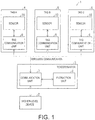
- FIG. 1 is a block diagram illustrating a configuration of a sensor information acquisition system 1 that includes a reader/writer 3 according to the first embodiment of the invention (details of each components of the sensor information acquisition system 1 will be described later).
- a sensor information acquisition system 1 that includes a reader/writer 3 according to the first embodiment of the invention (details of each components of the sensor information acquisition system 1 will be described later).
- an outline of a sensor information synchronization method that the reader/writer 3 illustrated in FIG. 1 executes will be described in order to facilitate understanding of the method.
- the reader/writer 3 transmits sensor information acquisition start commands for starting acquisition of sensor information to a tag A4, a tag B5, and a tag C6 respectively at different timings. Then, the tag A4, the tag B5, and the tag C6 respectively receive the sensor information acquisition start commands at different timings and respectively start the acquisition of sensor information at different timings based on the sensor information acquisition start commands.
- This configuration has a problem that the plurality of the sensor information that the reader/writer 3 has received from the tag A4, the tag B5, and the tag C6 are not synchronized.
- the reader/writer 3 extracts, from the plurality of the sensor information, a plurality of common period sensor information that the tag A4, the tag B5, and the tag C6 have acquired in a common period with reference to deviations of times at which the sensor information acquisition start commands have been transmitted to the tag A4, the tag B5, and the tag C6.
- the reader/writer 3 extracts, from the plurality of the sensor information, the sensor information (common period sensor information) that the tag A4, the tag B5, and the tag C6 have respectively acquired at or after the latest time among the respective times at which the sensor information acquisition start commands (acquisition start instructions) are transmitted to the tag A4, the tag B5, and the tag C6 in the process.
- the sensor information common period sensor information
- FIG. 2 is a diagram illustrating, in a time-series manner, communication between the higher-level device 2 and the reader/writer 3, contact between the reader/writer 3 and the tag A4 or the tag B5, and sampling cycles of the sensor information made by the tag A4 and the tag B5 ( FIG. 2 is a diagram similar to FIG. 10 ).
- the small triangular marks in FIG. 2 indicate sampling timings. (1) in FIG. 2 indicates one sampling cycle.
- the large triangular marks indicate acquisition start times of sensor information made by the tag A4 and the tag B5.
- time deviation indicated in (1) to (3) may occur in the contact between the reader/writer 3 and the tag A4 or the tag B5. In this manner, a problem may occur that the sensor information acquired by the tag A4 and the sensor information acquired by the tag B5 are not synchronized with each other.
- the tag A4 and the tag B5 perform sampling of the sensor information at the same sampling cycle.
- the sampling timing of the tag A4 and the sampling timing of the tag B5 are not synchronized with each other. Therefore, a time deviation may occur between the timing at which the sensor information is sampled by the tag A4 and the timing at which the sensor information is sampled by the tag B5.
- the higher-level device 2 or the like may correct the time deviation of the sensor information. In that case, the deviation between the sampling cycle of the tag A4 and the sampling cycle of the tag B5 can be half the time of these sampling cycles at maximum.
- the higher-level device 2 may generate the sensor information of the tag A4 according to the sampling timing of the sensor information of the tag B5 by interpolating the time-series sensor information of the tag A4 through interpolation.
- the time deviation illustrated as (2) in FIG. 2 may occur between the sensor information acquisition start time of the tag A4 and the sensor information acquisition start time of the tag B5.
- the sensor information acquisition start commands (acquisition start instructions) for starting acquisition of the sensor information are transmitted to each of the tag A4 and the tag B5 at the different timings (time-division transmission, and additionally, the tag A4 and the tag B5 start to acquire the sensor information at the same time of the end of the communication with the reader/writer 3, for example).
- a main purpose of the embodiment is to correct the time deviation of (2) in FIG. 2 . The correction for the time deviation will be described later.
- a time deviation may occur due to a difference between a period during which the tag A4 acquires the sensor information and a period during which the tag 135 acquires the sensor information as indicated by (3) in FIG. 2 .
- the correction for the time deviation will also be described later.
- FIG. 1 is a block diagram illustrating a configuration of the sensor information acquisition system 1 that includes the reader/writer 3 according to the embodiment as described above.
- the sensor information acquisition system 1 includes the higher-level device 2, the reader/writer 3 (sensor management device), the tag A4, the tag B5, and the tag C6.
- the tag A4, the tag B5, or the tag C6 are each attached to a plurality of robots, for example, to detect the respective operations of the plurality of robots in the embodiment.
- the higher-level device 2 is connected to the reader/writer 3 and transmits sensor information acquisition start commands (acquisition start instructions) to the reader/writer 3.
- sensor information acquisition start commands acquisition start instructions
- a personal computer or the like can be exemplified.
- the reader/writer 3 includes a communication unit 7 (that serves both as a transmission unit and as a receiving unit) and an extraction unit 8 and receives a plurality of sensor information from the tag A4, the tag B5, and the tag C6 (the plurality of wireless sensors).
- the communication unit 7 transmits sensor information acquisition start commands received from the higher-level device to each of the tag A4, the tag B5, and the tag C6 (the plurality of wireless sensors) at the different timings (time-division wireless transmission).
- the communication unit 7 receives a plurality of sensor information from each of the tag A4, the tag B5, and the C6 at the different timings.
- the extraction unit 8 extracts a plurality of common period sensor information that the tag A4, the tag B5, and the tag C6 have acquired in a common period from the plurality of sensor information that the communication unit 7 has received with reference to a deviation of time at which the communication unit 7 has transmitted the sensor information acquisition start commands to the tag A4, the tag B5, and the tag C6.
- Each of the tag A4, the tag B5, and the tag C6 (the plurality of wireless sensors) includes a tag communication unit 9 and a sensor 10, and the sensor 10 starts to acquire (measure) the sensor information based on the sensor information acquisition start command that the tag communication unit 9 has received from the communication unit 7 of the reader/writer 3 .
- the tag communication unit 9 transmits the sensor information that the sensor 10 has acquired to the communication unit 7.
- the sensor 10 of each of the tag A4, the tag B5, and the tag C6 acquires the sensor information by performing sampling for plural times at predetermined cycles in the common period.
- the tag A4, the tag B5, and the tag C6, passive tags, active tags, and the like in a radio frequency identifier (RFID) technology can be exemplified.
- the tag A4, the tag B5, and the tag C6 may or may not have a configuration for measuring time.
- the tag A4, the tag B5, and the tag C6 do not have any clocks that are synchronized with each other.
- FIG. 3 is a flowchart for describing the sensor information synchronization method that is performed by the reader/writer 3 according to the embodiment.
- the sensor information synchronization method performed by the reader/writer 3 according to the embodiment will be described with reference to FIG. 3 .
- the communication unit 7 of the reader/writer 3 receives the sensor information acquisition start commands (acquisition start instructions) from the higher-level device 2 (Step S0).
- the communication unit 7 transmits the sensor information acquisition start commands received from the higher-level device to each of the plurality of tag communication units 9 of the tag A4, the tag B5, and the tag C6 (the plurality of wireless sensors) at the different timings (Step S1).
- the respective sensors 10 of the tag A4, the tag B5. and the tag C6 start to acquire sensor information based on the sensor information acquisition start command that the tag communication units 9 have received (Step S2). Then, the respective tag communication units 9 of the tag A4, the tag B5, and the tag C6 transmit the acquired sensor information to the communication unit 7.
- the sensor information that the sensors 10 acquire acceleration data, environmental sound data, temperature data, and the like can be exemplified.
- timings at which the tag communication units 9 transmit the sensor information to the communication unit 7 are received, timings at which data collection instruction commands, which will be described later, are received, timings at which built-in memories store the sensor information up to upper limits of capacity, timings at which a predetermined period elapses from the start of the acquisition of the sensor information, and the like can be exemplified.
- the time at which the communication unit 7 transmits the sensor information acquisition start commands to the tag communication units 9 (the time at which the transmission is completed) and the time at which the sensors 10 starts to acquire the sensor information are substantially the same.
- the communication unit 7 of the reader/writer 3 receives the sensor information from the respective tag communication units 9 of the tag A4. the tag B5, and the tag C6 (Step S3).
- the extraction unit 8 extracts the plurality of the common period sensor information that the tag A4, the tag B5, and the tag C6 have acquired in a common period from the plurality of the sensor information that the communication unit 7 has received in Step S3 with reference to the deviation of the times at which the communication unit 7 has transmitted the sensor information acquisition start commands to the respective tag communication units 9 of the tag A4, the tag B5, and the tag C6 in Step S1 (Step S4). Details of the method by which the extraction unit 8 extracts the common period sensor information will be described later.
- the communication unit 7 transmits the plurality of common period sensor information that the extraction unit 8 has extracted in Step S4 to the higher-level device 2 (Step S5).
- the reader/writer 3 (sensor management device) is a sensor management device that receives a plurality of sensor information from the tag A4, the tag B5, and the tag C6 (the plurality of wireless sensors) that each acquires the sensor information by performing sampling for plural times at the predetermined cycles in the common period, and the reader/writer 3 includes the communication unit 7 (transmission unit) that transmits the sensor information acquisition start commands (acquisition start instructions) for starting the acquisition of the sensor information to each of the tag A4, the tag B5, and the tag C6 (the plurality of wireless sensor) at the different timings and the extraction unit that extracts the plurality of common period sensor information that the tag A4, the tag B5, and the tag C6 have acquired in the common period from the plurality of sensor information with reference to the deviation of the times at which the communication unit 7 has transmitted the sensor information acquisition start commands to the tag A4, the tag B5, and the tag C6.
- FIG. 4 is a diagram illustrating, a time-series manner, communication between the higher-level device 2 and the reader/writer 3 and communication (contact) between the reader/writer 3 and the tag A4, the tag B5, or the tag C6 according to the embodiment.
- a specific method of extracting the common period sensor information in Step S4 described above will be described with reference to FIG. 4 .
- the tag A4, the tag B5, and the tag C6 each receive the sensor information acquisition start commands at the different timings (Step S1) and execute acquisition of the sensor information at the different timings (Step S2) (the acquisition of the sensor information is started at the timing at which the communication between the reader/writer 3 and the tag A4, the tag B5, or the tag C6 ends). Therefore, there is a problem that the plurality of sensor information that the reader/writer 3 has received from the tag A4, the tag B5, and the tag C6 are not synchronized with each other.
- the extraction unit 8 refers to the deviation between the time at which the communication unit 7 has transmitted the sensor information acquisition start command to the tag communication unit 9 of the tag A4 in Step S1 and the time at which the communication unit 7 has transmitted the sensor information acquisition start command to the tag communication unit 9 of the tag C6 in Step S1. Then, the extraction unit 8 cuts the sensor information (the portion surrounded by the dotted line in FIG. 4 ) that the sensor 10 of the tag A4 has acquired at or before the time at which the communication unit 7 has transmitted the sensor information acquisition start command to the tag communication unit 9 of the tag C6 (the time at which the sensor 10 of the tag C6 has started to acquire the sensor information).
- the extraction unit 8 refers to the deviation between the time at which the communication unit 7 has transmitted the sensor information acquisition start command to the tag communication unit 9 of the tag B5 in Step S1 and the time at which the communication unit 7 has transmitted the sensor information acquisition start command to the tag communication unit 9 of the tag C6 in Step S1. Then, the extraction unit 8 cuts the sensor information (the portion surrounded by the dotted line in FIG. 4 ) that the sensor 10 of the tag B5 has acquired at or before the time at which the communication unit 7 has transmitted the sensor information acquisition start command to the tag communication unit 9 of the tag C6 (the time at which the sensor 10 of the tag C6 has started to acquire the sensor information).
- the extraction unit 8 extracts the sensor information (common period sensor information) that each of the plurality of sensors 10 of the tag A4, the tag B5, and the tag C6 has acquired at or after the latest time (the time at which the sensor 10 of the tag C6 has started to acquire the sensor) among the respective times at which the communication unit 7 (transmission unit) has transmitted the sensor information acquisition start commands (acquisition start instructions) to the respective tag communication units 9 of the tag A4, the tag B5, and the tag C6 from the plurality of the sensor information that the communication unit 7 has received in Step S3.
- the sensor information acquisition start commands acquisition start instructions
- the common period sensor information is extracted from other sensor information in accordance with the latest time at which the acquisition start instruction for starting the acquisition of the sensor information is transmitted, that is, the latest acquisition start time at which the wireless sensor has started to acquire the sensor information. In this manner, it is possible to synchronize the plurality of the sensor information while minimizing useless sensor information that is not used by cutting only the sensor information that has not been synchronized.
- the tag A4, the tag B5, and the tag C6 each transmit the sensor information to the reader/writer 3 at the different timings as illustrated by the hatching in FIG. 4 (Step S3). Therefore, there is a problem that the plurality of sensor information that the reader/writer 3 has received from the tag A4, the tag B5, and the tag C6 have not been synchronized.
- the extraction unit 8 refers to deviation between the time at which the communication unit 7 has started to receive the sensor information from the tag communication unit 9 of the tag A4 in Step S3 and the time at which the communication unit 7 has started to receive the sensor information from the tag communication unit 9 of the tag C6 in Step S3. Then, the extraction unit 8 cuts the sensor information (the portion surrounded by the dotted line in FIG. 4 ) that the sensor 10 of the tag C6 has acquired at or after the time at which the communication unit 7 has started to receive the sensor information from the tag communication unit 9 of the tag A4.
- the extraction unit 8 refers to the deviation between the time at which the communication unit 7 has started to receive the sensor information from the tag communication unit 9 of the tag A4 in Step S3 and the time at which the communication unit 7 has started to receive the sensor information from the tag communication unit 9 of the tag B5 in Step S3. Then, the extraction unit 8 cuts the sensor information (the portion surrounded by the dotted line in FIG. 4 ) that the sensor 10 of the tag B5 has acquired at or after the time at which the communication unit 7 has started to receive the sensor information from the tag communication unit 9 of the tag A4.
- the extraction unit 8 extracts the sensor information (common period sensor information) that each of the plurality of sensors 10 of the tag A4, the tag B5, and the tag C6 has acquired at or before the earliest time (in the above example, the time at which the communication unit 7 has started to receive the sensor information from the tag communication unit 9 of the tag A4) among the respective times at which the communication unit 7 (receiving unit) has started to receive the plurality of the sensor information from the respective tag communication units 9 of the tag A4, the tag B5, and the tag C6 from the plurality of the sensor information that the communication unit 7 has received in Step S3.
- the sensor information common period sensor information
- the common period sensor information is extracted from other sensor information in accordance with the earliest reception start time at which the reception of the sensor information has been started, that is, the earliest acquisition completion time at which the wireless sensor has completed the acquisition of the sensor information. In this manner, it is possible to synchronize the plurality of the sensor information while minimizing useless sensor information that is not used by cutting only the sensor information that has not been synchronized.
- FIG. 5 is a flowchart for describing a sensor information synchronization method that is performed by a reader/writer 3 according to a modification example of the embodiment.
- FIG. 6 is a diagram illustrating, in a time-series manner, communication between the higher-level device 2 and the reader/writer 3 and communication (contact) of the reader/writer 3, the tag A4, the tag B5, or the tag C6 according to the modification example of the embodiment.
- the sensor information synchronization method that is performed by the reader/writer 3 according to the modification example of the embodiment will be described with reference to FIG. 5 .
- detailed description of processes that are similar to those in the above sensor information synchronization method according to the embodiment will be omitted.
- the communication unit 7 of the reader/writer 3 receives the sensor information acquisition start commands (acquisition start instructions) from the higher-level device 2 (Step S10).
- the communication unit 7 transmits the sensor information acquisition start commands received from the higher-level device to each of the plurality of tag communication units 9 of the tag A4, the tag B5, and the tag C6 (the plurality of wireless sensors) at the different timings (Step S11).
- Step S12 the respective sensors 10 of the tag A4, the tag B5, and the tag C6 start to acquire the sensor information based on the sensor information acquisition start commands that the tag communication units 9 have received.
- the communication unit 7 of the reader/writer 3 receives data collection instruction commands (transmission instructions) from the higher-level device 2 (Step S13).
- the communication unit 7 transmits the data collection instruction commands received from the higher-level device to each of the plurality of tag communication units 9 of the tag A4, the tag B5, and the tag C6 (the plurality of wireless sensors) at the different timings (Step S14). Then, the respective tag communication units 9 of the tag A4, the tag B5, and the tag C6 transmits the sensor information to the communication unit 7 based on the data collection instruction commands.
- the communication unit 7 receives the sensor information from the respective tag communication units 9 of the tag A4, the tag B5, and the tag C6 (Step S15).
- the time at which the communication unit 7 has transmitted the data collection instruction commands to the tag communication units 9 and the time at which the communication unit 7 has started to receive the sensor information from the tag communication units 9 are substantially the same.
- the extraction unit 8 of the reader/writer 3 extracts the plurality of the common period sensor information that the tag A4, the tag B5, and the tag C6 have acquired in the common period from the plurality of the sensor information that the communication unit 7 has received in Step S3 with reference to the deviation of times at which the communication unit 7 has transmitted the sensor information acquisition start commands to the respective tag communication units 9 of the tag A4, the tag B5, and the tag C6 in Step S1 (Step S16).
- the communication unit 7 of the reader/writer 3 transmits the plurality of the common period sensor information extracted in Step S4 to the higher-level device 2 (Step S17).
- the tag A4, the tag B5, and the tag C6 each transmit the sensor information to the reader/writer at the different timings based on the data collection instruction commands (Step S14). Therefore, there is a problem that the plurality of the sensor information that the reader/writer 3 has received from the tag A4, the tag B5, and the tag C6 have not been synchronized.
- the extraction unit 8 refers to the deviation between the time at which the communication unit 7 has transmitted the data collection instruction command to the tag communication unit 9 of the tag A4 in Step S14 and the time at which the communication unit 7 has transmitted the data collection instruction command to the tag communication unit 9 of the tag C6 in Step S14. Then, the extraction unit 8 cuts the sensor information (the portion surrounded by the dotted line in FIG. 6 ) that the sensor 10 of the tag C6 has acquired at or after the time at which the communication unit 7 has transmitted the data collection instruction command to the tag communication unit 9 of the tag A4.
- the extraction unit 8 refers to the deviation between the time at which the communication unit 7 has transmitted the data collection instruction command to the tag communication unit 9 of the tag A4 in Step S14 and the time at which the communication unit 7 has transmitted the data collection instruction command to the tag communication unit 9 of the tag B5 in Step S14. Then, the extraction unit 8 cuts the sensor information (the portion surrounded by the dotted line in FIG. 6 ) that the sensor 10 of the tag B5 has acquired at or after the time at which the communication unit 7 has transmitted the data collection instruction command to the tag communication unit 9 of the tag A4.
- the extraction unit 8 extracts the sensor information (common period sensor information) that each of the plurality of sensors 10 of the tag A4, the tag B5, and the tag C6 has acquired at or before the earliest time (in the aforementioned example, the time at which the communication unit 7 has transmitted the data collection instruction command to the tag communication unit 9 of the tag A4) among the respective times at which the communication unit 7 (transmission unit) has transmitted the data collection instruction commands (transmission instructions) to the respective tag communication unit 9 of the tag A4, the tag B5, and the tag C6 from the plurality of the sensor information that the communication unit 7 has received in Step S15.
- the sensor information common period sensor information
- the common period sensor information is extracted from other sensor information in accordance with the earliest time at which the transmission instruction for transmitting the sensor information is transmitted, that is, the earliest acquisition completion time at which the wireless sensor has completed the acquisition of the sensor information. In this manner, it is possible to synchronize the plurality of the sensor information while minimizing useless sensor information that is not used by cutting only the sensor information that has not been synchronized.
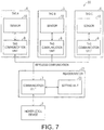
- Fig, 7 is a block diagram illustrating a configuration of a sensor information acquisition system 20 that includes a reader/writer 21 according to the embodiment.
- the sensor information acquisition system 20 has a configuration that is similar to that of the sensor information acquisition system 20 according to the first embodiment except that the reader/writer 21 includes a setting unit 22 instead of the extraction unit 8.
- the setting unit 22 sets a delay time with which acquisition of the sensor information is delayed for the tag A4, the tag B5, and the tag C6 with reference to the deviation of the respective times at which the communication unit 7 transmits the sensor information acquisition start commands (acquisition start instructions) to the plurality of tag communication units 9 of the tag A4. the tag B5, and the tag C6.
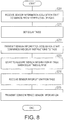
- FIG. 8 is a flowchart for describing a sensor information synchronization method that is performed by the reader/writer 21 according to the embodiment.
- the sensor information synchronization method that is performed by the reader/writer 21 according to the embodiment will be described with reference to FIG. 8 .
- the communication unit 7 of the reader/writer 21 receives sensor information acquisition start commands (acquisition start instructions) from a higher-level device 2 (Step S20).
- the setting unit 22 sets delay times with which the acquisition of the sensor information is delayed for the tag A4, the tag B5, and the tag C6 with reference to the deviation of the respective times at which the communication unit 7 transmits the sensor information acquisition start commands to the plurality of tag communication units 9 of the tag A4, the tag B5, and the tag C6 (Step S21). Details of the method by which the setting unit 22 sets the delay times will be described later. Note that it is assumed that the setting unit 22 has recognized, in advance, the respective times at which the sensor information acquisition start commands are transmitted to the plurality of tag communication units 9 of the tag A4, the tag B5, and the tag C6.
- the communication unit 7 transmits delay instructions for delaying acquisition of the sensor information during the delay times from the respective times at which the sensor information acquisition start commands have been transmitted to the plurality of tag communication units 9 of the tag A4, the tag B5, and the tag C6 (the delay time set in Step S21) and the sensor information acquisition start commands received from the higher-level device to each of the plurality of tag communication units 9 of the tag A4, the tag B5, and the tag C6 at the different timings (Step S22).
- the respective sensors 10 of the tag A4. the tag B5, and the tag C6 start to acquire the sensor information based on the sensor information acquisition start commands when the relay times indicated by the delay instructions elapse from the times (the times at which the communication unit 7 has transmitted the delay instructions) at which the tag communication units 9 have received the delay instructions (Step S23). Then, the respective tag communication units 9 of the tag A4, the tag B5, and the tag C6 transmit the acquired sensor information to the communication unit 7.
- the communication unit 7 receives the sensor information (common period sensor information) from the respective tag communication units 9 of the tag A4, the tag B5. and the tag C6 (Step S24).
- the communication unit 7 transmits a plurality of common period sensor information received in Step S24 to the higher-level device 2 (Step S25).
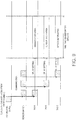
- FIG. 9 is a diagram illustrating, in a time-series manner, communication between the higher-level device 2 and the reader/writer 21 and communication (contact) between the reader/writer 21 and the tag A4, the tag B5, or the tag C6 according to the embodiment.
- a specific example of the method of setting the delay times in Step S21 described above will be described with reference to FIG. 9 .
- the communication between the reader/writer 21 and the tag A4, the tag B5, and the tag C6 is performed in a time division manner. Therefore. there is a problem that the reader/writer 21 acquires a plurality of sensor information that have not been synchronized from the tag A4, the tag B5, and the tag C6 in a case that the tag A4, the tag B5, and the tag C6 each receive the sensor information acquisition start commands at the different timings and execute the acquisition of the sensor information at the different timings immediately after receiving the sensor information acquisition start command.
- the setting unit 22 refers to the deviation between the time at which the communication unit 7 transmits the sensor information acquisition start command to the tag communication unit 9 of the tag A4 in Step S22 and the time at which the communication unit 7 transmits the sensor information acquisition start command to the tag communication unit 9 of the tag C6 in Step S22. Then, the setting unit 22 sets a delay time for causing the sensor 10 of the tag A to start to acquire the sensor information at or after the time at which the communication unit 7 transmits the sensor information acquisition start command to the tag communication unit 9 of the tag C6 (the time at which the transmission is completed) in Step S22. Also, the setting unit 22 sets a delay time for causing the acquisition of the sensor information to be delayed in the sensor 10 of the tag C until the time at which the sensor 10 of the tag A starts to acquire the sensor information by further referring to the delay time.
- the setting unit 22 refers to the deviation between the time at which the communication unit 7 transmits the sensor information acquisition start command to the tag communication unit 9 of the tag A4 in Step S22 and the time at which the communication unit 7 transmits a sensor information acquisition start command to the tag communication unit 9 of the tag B5 in Step S22. Then, the setting unit 22 sets the delay time for causing the acquisition of the sensor information by the sensor 10 of the tag B to be delayed up to the time at which the sensor 10 of the tag A starts to acquire the sensor information by further referring to the above delay time for the sensor 10 of the tag A.
- the setting unit 22 sets the delay times for the respective tags, and the respective sensors 10 of the tag A4, the tag B5, and the tag C6 start to acquire the sensor information based on the sensor information acquisition start commands when the delay times elapse from the times at which the tag communication units 9 receive the delay instructions (the times at which the communication unit 7 transmits the delay instructions) in Step S23 described above.
- the respective sensors 10 of the tag A4, the tag B5, and the tag C6 are caused to acquire the common period sensor information in the common period.
- the reader/writer 21 (sensor management device) according to the embodiment further includes a setting unit that sets delay times with which acquisition of the sensor information is delayed for the tag A4, the tag B5, and the tag C6 with reference to deviation of the respective times at which the communication unit 7 (transmission unit) transmits the sensor information acquisition start commands (acquisition start instructions) to the tag A4, the tag B5, and the tag C6.
- the reader/writer 21 causes each of the tag A4, the tag B5, and the tag C6 to acquire the common period sensor information in the common period by further transmitting the delay instructions for causing acquisition of the sensor information to be delayed to the tag A4, the tag B5, and the tag C6 during the delay times from the respective times at which the communication unit 7 (transmission unit) has transmitted the sensor information acquisition start commands (acquisition start instructions) to the tag A4, the tag B5, and the tag C6.
- the reader/writer 21 further includes the extraction unit 8, and after Step S24 described above, the extraction unit 8 extracts the sensor information that each of the plurality of sensors 10 of the tag A4, the tag B5, and the tag C6 has acquired at or after the latest time among the respective times at which the communication unit 7 (transmission unit) has transmitted the sensor information acquisition start commands to the respective tag communication units 9 of the tag A4, the tag B5, and the tag C6 from the plurality of sensor information that the communication unit 7 has received.
- the extraction unit 8 extracts the sensor information that each of the plurality of sensors 10 of the tag A4, the tag B5, and the tag C6 has acquired at or before the earliest time among the respective times at which the communication unit 7 has transmitted the data collection instruction commands to the respective tag communication units 9 of the tag A4, the tag B5, and the tag C6 from the plurality of sensor information that the communication unit 7 has received.
- Control blocks (particularly, the extraction unit 8 and the setting unit 22) of the reader/writer 3 and the reader/writer 21 (sensor management device) may be implemented by logical circuits (hardware) formed on integrated circuits (IC chips) or the like or may be implemented by software.
- the reader/writer 3 and the reader/writer 21 include computers that execute instructions of a program that is software for implementing the respective functions.
- Each of the computers includes one or more processor, for example, and includes a computer-readable recording medium that stores the program therein.
- the object of the invention is achieved by the processor reading the program from the recording medium and executing the program in the computer.
- a central processing unit CPU
- the recording medium a tape, a disc, a card, a semiconductor memory, a programmable logical circuit, or the like can be used as well as a "non-transitory tangible medium" such as a read only memory (ROM), for example.
- ROM read only memory
- a random access memory (RAM) that develops the program and the like may further be provided.
- the program may be supplied to the computer via an arbitrary transmission medium (such as a communication network or broadcasting waves) capable of transmitting the program.
- a transmission medium such as a communication network or broadcasting waves
- an aspect of the invention can also be implemented in the form of data signals incorporated in carrier waves in which the program is realized through electronic transmission.
Landscapes
- Engineering & Computer Science (AREA)
- Physics & Mathematics (AREA)
- Health & Medical Sciences (AREA)
- Toxicology (AREA)
- Computer Networks & Wireless Communication (AREA)
- Artificial Intelligence (AREA)
- Electromagnetism (AREA)
- General Health & Medical Sciences (AREA)
- Computer Vision & Pattern Recognition (AREA)
- General Physics & Mathematics (AREA)
- Theoretical Computer Science (AREA)
- Signal Processing (AREA)
- Computer Security & Cryptography (AREA)
- Arrangements For Transmission Of Measured Signals (AREA)
- Synchronisation In Digital Transmission Systems (AREA)
- Selective Calling Equipment (AREA)
Abstract
Description
- The present invention mainly relates to a sensor management device that receives a plurality of sensor information from a plurality of wireless sensors that each acquire the sensor information.
- A technology in which a sensor management device (for example, a reader/writer) communicates with a plurality of wireless sensors (for example, RFID tags) in a time division manner is known. According to the technology, the sensor management device receives a plurality of sensor information from the plurality of wireless sensors that each acquire the sensor information in a time division manner.
- As literatures describing the above technology of receiving a plurality of sensor information from a plurality of sensors,
Patent Document 1 andPatent Document 2 are exemplified. -
Patent Document 1 describes a synchronous measurement system that has a controller and a sensor unit connected to the controller. The synchronous measurement system synchronizes measurement data by the controller sending a plurality of synchronization commands to the sensor unit at predetermined intervals and the sensor unit synchronizing each of the plurality of synchronization commands to send the measurement data to the controller. -
Patent Document 2 describes a method and an apparatus for synchronizing sensor data of sensor objects, which are obtained by at least one or more sensors at measurement timings unique to the sensors, with a common time base that is formed with a plurality of base timings. The method and the apparatus synchronize the sensor data with the common time base by using parameters that characterize the sensor objects as the sensor data to obtain parameter values at the base timings based on the measurement timings and the parameter values at the measurement timings. -
- [Patent Document 1] Japanese Laid-Open Application No.
2014-178952 (published on September 25, 2014 - [Patent Document 2] Japanese Laid-Open Application No.
2004-535586 (published on November 25, 2004 -
FIG. 10 is a diagram illustrating, in a time-series manner, communication between a higher-level device and a reader/writer and communication (contact) of a tag A, a tag B, or a tag C with the reader/writer in the aforementioned technology in which a sensor management device (for example, the reader/writer) communicates with a plurality of wireless sensors (tags) in a time division manner (the horizontal axis represents a time). As illustrated by hatching inFIG. 10 , since the communication between the reader/writer and the tag A, the tag B, and the tag C is performed in a time division manner, the tag A, the tag B, and the tag C each receive sensor information acquisition start commands at different timings and each execute acquisition of the sensor information at different timings (the acquisition of the sensor information is started at a timing at which communication between the reader/writer and the tag A, the tag B, or the tag C is completed). Also, the tag A, the tag B, and the tag C each receive data collection instruction commands at different timings and each transmit the sensor information to the reader/writer at different timings. Therefore, there is a problem that the plurality of sensor information that the reader/writer has received from the tag A, the tag B, and the tag C are not synchronized with each other. - There is a problem that it is not possible to accurately analyze the sensor information if the plurality of sensor information received from the plurality of wireless sensors are not synchronized. In a configuration in which wireless sensors are each attached to a plurality of robots, for example, there is a problem that consistency cannot be kept between operation content indicated by the sensor information and actual operation content if time deviation is present when coordinated operations of the plurality of robots are measured.
- Therefore, it is necessary to synchronize the plurality the sensor information even in the technology in which the sensor management device communicates with the plurality of wireless sensors in a time division manner as in the above technologies described in
Patent Documents - An aspect of the invention was made in view of the above problems, and an object thereof is to provide a technology that enables synchronization of a plurality of sensor information for a technology in which a sensor management device communicates with a plurality of wireless sensors in a time division manner.
- In order to solve the aforementioned problems, according to an aspect of the invention, there is provided a sensor management device that receives a plurality of sensor information from a plurality of wireless sensors that acquire the sensor information respectively by performing sampling for plural times at predetermined cycles in a common period, the sensor management device including: a transmission unit that transmits acquisition start instructions for starting acquisitions of the plurality of sensor information to the plurality of wireless sensors respectively at different timings; and an extraction unit that extracts a plurality of common period sensor information, which the plurality of wireless sensors have acquired in the common period, from the plurality of sensor information with reference to deviation of times at which the transmission unit has transmitted the acquisition start instructions to the plurality of wireless sensors.
- With the above configuration, it is possible to recognize the respective times at which the plurality of wireless sensors starts to acquire the sensor information merely by referring to the respective timings at which the acquisition start instructions for starting the acquisition of the sensor information are transmitted to the plurality of wireless sensors. In this manner, it is possible to synchronize the plurality of sensor information transmitted in a time division manner with each other. Also, it is possible to synchronize the plurality of sensor information even if the wireless sensors do not have a configuration for measuring time.
- In the sensor management device according to the aspect of the invention, the extraction unit may extract, from the plurality of sensor information, the plurality of common period sensor information that the plurality of wireless sensors has acquired respectively at or after a time that is the latest among respective times at which the transmission unit transmits the acquisition start instructions to the plurality of wireless sensors.
- With the above configuration, the plurality of common period sensor information is extracted among other sensor information in accordance with the time that is the latest among the times at which the acquisition start instructions for starting the acquisition of the sensor information are transmitted, that is, in accordance with an acquisition start time at which the wireless sensor starts to acquire the sensor information at the latest time. In this manner, it is possible to synchronize the plurality of sensor information while minimizing useless sensor information that is not used by cutting only sensor information that has not been synchronized.
- The sensor management device according to the aspect of the invention may further include a receiving unit that receives the plurality of sensor information respectively from the plurality of wireless sensors at different timings, and the extraction unit may extract, from the plurality of sensor information, the plurality of common period sensor information that the plurality of wireless sensors have acquired respectively at or before a time that is the earliest among respective times at which the receiving unit starts to receive the plurality of sensor information from the plurality of wireless sensors.
- With the above configuration, the plurality of common period sensor information is extracted from other sensor information in accordance with a reception start time at which reception of the sensor information is started at the earliest time, that is, an acquisition completion time at which the wireless sensor completes the acquisitions of the plurality of sensor information at the earliest time. In this manner, it is possible to synchronize the plurality of sensor information while minimizing useless sensor information that is not used by cutting only the sensor information that has not been synchronized.
- In the sensor management device according to the aspect of the invention, the transmission unit may further transmit transmission instructions for causing the plurality of sensor information to be transmitted to the plurality of wireless sensors respectively at different timings, and the extraction unit may extract, from the plurality of sensor information, common period sensor information that the plurality of wireless sensors have each acquired at or before a time that is the earliest among respective times at which the transmission unit transmits the transmission instructions to the plurality of wireless sensors.
- With the above configuration, the plurality of common period sensor information is extracted from other sensor information in accordance with the time that is the earliest time at which the transmission instruction for causing the sensor information to be transmitted is transmitted, that is, an acquisition completion time at which the wireless sensor completes the acquisitions of the plurality of sensor information at the earliest time. In this manner, it is possible to synchronize a plurality of sensor information while minimizing useless the sensor information that is not used by cutting only the sensor information that has not been synchronized.
- According to an aspect of the invention, there is provided a sensor management device that receives a plurality of sensor information from a plurality of wireless sensors that acquire the sensor information respectively by performing sampling for plural times at predetermined cycles in a common period, the sensor management device including: a transmission unit that transmits acquisition start instructions for the plurality of sensor information to the plurality of wireless sensors respectively at different timings; and a setting unit that sets delay times, with which acquisitions of the sensor information are delayed, for the plurality of wireless sensors respectively with reference to deviations of respective times at which the transmission unit has transmitted the acquisition start instructions to the plurality of wireless sensors. The transmission unit causes the plurality of wireless sensors to acquire common period sensor information respectively in the common period by further transmitting delay instructions for causing the acquisitions of the plurality of sensor information to be delayed to the plurality of wireless sensors in the delay times from the respective times at which the acquisition start instructions are transmitted to the plurality of wireless sensors.
- With the above configuration, it is possible to set the respective delay times with which the sensor information acquisition start times of the wireless sensors are synchronized merely by referring to the respective timings at which the sensor information acquisition start commands for starting the acquisitions of the plurality of sensor information are transmitted to the plurality of wireless sensors. In this manner, it is possible to synchronize the plurality of sensor information transmitted in a time division manner. Also, it is not necessary to cut the sensor information that has not been synchronized, and it is possible to acquire the synchronized sensor information up to the upper limit of storage capacity using the wireless sensors. In addition, since useless the sensor information that is not to be used is not acquired, it is possible to suppress power consumption of the wireless sensors.
- According to an aspect of the invention, there is provided a sensor information synchronization method that is performed by a sensor management device that receives a plurality of sensor information from a plurality of wireless sensors that acquire the sensor information respectively by performing sampling for plural times at predetermined cycles in a common period, the method including: transmitting acquisition start instructions for starting acquisitions of the plurality of sensor information to the plurality of wireless sensors respectively at different timings; and extracting a plurality of common period sensor information that the plurality of wireless sensors have acquired in the common period from the plurality of sensor information with reference to deviation of times at which the acquisition start instructions have been transmitted to the plurality of wireless sensors during transmitting the acquisition start instructions.
- With the above configuration, it is possible to recognize the respective times at which the plurality of wireless sensors starts to acquire the sensor information merely by referring to the respective timings at which the acquisition start instructions for starting the acquisitions of the plurality of sensor information are transmitted to the plurality of wireless sensors. In this manner, it is possible to synchronize the plurality of sensor information transmitted in a time division manner. Also, it is possible to synchronize the plurality of sensor information even if the wireless sensors do not have a configuration for measuring time.
- According to an aspect of the invention, there is provided a sensor information synchronization method that is performed by a sensor management device that receives a plurality of sensor information from a plurality of wireless sensors that acquire the plurality of sensor information respectively by performing sampling for plural times at predetermined cycles in a common period, the method including: transmitting acquisition start instructions for the plurality of sensor information to the plurality of wireless sensors respectively at different timings; and setting delay times, with which acquisitions of the sensor information are delayed, for the plurality of wireless sensors respectively with reference to deviation of respective times at which the acquisition start instructions have been transmitted to the plurality of wireless sensors during transmitting the acquisition start instructions During transmitting the acquisition start instructions, the plurality of wireless sensors is caused to acquire common period sensor information respectively in the common period by further transmitting delay instructions for causing the acquisitions of the sensor information to be delayed to the plurality of wireless sensors in the delay times from respective times at which the acquisition start instructions arc transmitted to the plurality of wireless sensors.
- With the above configuration, it is possible to set the respective delay times with which the sensor information acquisition start times of the wireless sensors are synchronized merely by referring to the respective timings at which the sensor information acquisition start commands for starting the acquisition of the sensor information are transmitted to the plurality of wireless sensors. In this manner, it is possible to synchronize the plurality of sensor information transmitted in a time division manner. Also, it is not necessary to cut the sensor information that has not been synchronized, and it is possible to acquire the synchronized sensor information up to the upper limit of storage capacity using the wireless sensors. In addition, since it is not necessary to acquire useless sensor information that is not used, it is possible to suppress power consumption of the wireless sensors.
- According to an aspect of the invention, a technology that enables synchronization of a plurality of sensor information for a technology in which a sensor management device communicates with a plurality of wireless sensors in a time division manner is provided.
- Embodiments will now be described, by way of example only, with reference to the accompanying drawings which are meant to be exemplary, not limiting, and wherein like elements are numbered alike in several figures, in which:
-
FIG. 1 is a block diagram illustrating a configuration of a sensor information acquisition system that includes a reader/writer according to a first embodiment of the invention. -
FIG. 2 is a diagram illustrating, in a time-series manner, cycles of communication between a higher-level device and the reader/writer, contact of a tag A or a tag B with the reader/writer, and sampling of sensor information with the tag A and the tag B according to the first embodiment of the invention. -
FIG. 3 is a flowchart for describing a sensor information synchronization method that is performed by the reader/writer according to the first embodiment of the invention. -
FIG. 4 is a diagram illustrating, in a time-series manner, communication between the higher-level device and the reader/writer and communication of the tag A, the tag B, or a tag C with the reader writer according to the first embodiment of the invention. -
FIG. 5 is a flowchart for describing a sensor information synchronization method that is performed by a reader/writer according to a modification example of the first embodiment of the invention. -
FIG. 6 is a diagram illustrating, in a time-series manner, communication between a higher-level device and a reader/writer and communication of a tag A, a tag B, or a tag C with the reader/writer according to a modification example of the first embodiment of the invention. -
FIG. 7 is a block diagram illustrating a configuration of a sensor information acquisition system that includes a reader/writer according to a second embodiment of the invention. -
FIG. 8 is a flowchart for describing a sensor information synchronization method that is performed by the reader/writer according to the second embodiment of the invention. -
FIG. 9 is a diagram illustrating, in a time-series manner, communication between a higher-level device and the reader/writer and communication of a tag A, a tag B, or a tag C with the reader/writer according to the embodiment. -
FIG. 10 is a diagram illustrating, in a time-series manner, communication between a higher-level device and a reader/writer and communication of a tag A, a tag B, or a tag C with a reader/writer according to the related art. - Hereinafter, an embodiment according to an aspect of the invention (hereinafter, also referred to as "the embodiment") will be described in detail. However, the configuration described in the embodiment is not intended to limit the scope of the invention and is merely an example for explanation unless particularly specified otherwise.
-
FIG. 1 is a block diagram illustrating a configuration of a sensorinformation acquisition system 1 that includes a reader/writer 3 according to the first embodiment of the invention (details of each components of the sensorinformation acquisition system 1 will be described later). First, an outline of a sensor information synchronization method that the reader/writer 3 illustrated inFIG. 1 executes will be described in order to facilitate understanding of the method. - The reader/
writer 3 transmits sensor information acquisition start commands for starting acquisition of sensor information to a tag A4, a tag B5, and a tag C6 respectively at different timings. Then, the tag A4, the tag B5, and the tag C6 respectively receive the sensor information acquisition start commands at different timings and respectively start the acquisition of sensor information at different timings based on the sensor information acquisition start commands. This configuration has a problem that the plurality of the sensor information that the reader/writer 3 has received from the tag A4, the tag B5, and the tag C6 are not synchronized. - Thus, the reader/
writer 3 according to the embodiment extracts, from the plurality of the sensor information, a plurality of common period sensor information that the tag A4, the tag B5, and the tag C6 have acquired in a common period with reference to deviations of times at which the sensor information acquisition start commands have been transmitted to the tag A4, the tag B5, and the tag C6. - For example, according to an aspect of the embodiment, the reader/
writer 3 extracts, from the plurality of the sensor information, the sensor information (common period sensor information) that the tag A4, the tag B5, and the tag C6 have respectively acquired at or after the latest time among the respective times at which the sensor information acquisition start commands (acquisition start instructions) are transmitted to the tag A4, the tag B5, and the tag C6 in the process. -
FIG. 2 is a diagram illustrating, in a time-series manner, communication between the higher-level device 2 and the reader/writer 3, contact between the reader/writer 3 and the tag A4 or the tag B5, and sampling cycles of the sensor information made by the tag A4 and the tag B5 (FIG. 2 is a diagram similar toFIG. 10 ). In addition, the small triangular marks inFIG. 2 indicate sampling timings. (1) inFIG. 2 indicates one sampling cycle. The large triangular marks indicate acquisition start times of sensor information made by the tag A4 and the tag B5. Hereinafter, an object on which the reader/writer 3 is to perform time correction according to the embodiment will be described with reference toFIG. 2 . As illustrated inFIG. 2 , time deviation indicated in (1) to (3) may occur in the contact between the reader/writer 3 and the tag A4 or the tag B5. In this manner, a problem may occur that the sensor information acquired by the tag A4 and the sensor information acquired by the tag B5 are not synchronized with each other. - The tag A4 and the tag B5 perform sampling of the sensor information at the same sampling cycle. However, the sampling timing of the tag A4 and the sampling timing of the tag B5 are not synchronized with each other. Therefore, a time deviation may occur between the timing at which the sensor information is sampled by the tag A4 and the timing at which the sensor information is sampled by the tag B5. However, even in a case that the time deviation occurs, the higher-
level device 2 or the like may correct the time deviation of the sensor information. In that case, the deviation between the sampling cycle of the tag A4 and the sampling cycle of the tag B5 can be half the time of these sampling cycles at maximum. For example, the higher-level device 2 may generate the sensor information of the tag A4 according to the sampling timing of the sensor information of the tag B5 by interpolating the time-series sensor information of the tag A4 through interpolation. - In addition, the time deviation illustrated as (2) in
FIG. 2 may occur between the sensor information acquisition start time of the tag A4 and the sensor information acquisition start time of the tag B5. This is because the sensor information acquisition start commands (acquisition start instructions) for starting acquisition of the sensor information are transmitted to each of the tag A4 and the tag B5 at the different timings (time-division transmission, and additionally, the tag A4 and the tag B5 start to acquire the sensor information at the same time of the end of the communication with the reader/writer 3, for example). A main purpose of the embodiment is to correct the time deviation of (2) inFIG. 2 . The correction for the time deviation will be described later. - In addition, a time deviation may occur due to a difference between a period during which the tag A4 acquires the sensor information and a period during which the tag 135 acquires the sensor information as indicated by (3) in
FIG. 2 . The correction for the time deviation will also be described later. -
FIG. 1 is a block diagram illustrating a configuration of the sensorinformation acquisition system 1 that includes the reader/writer 3 according to the embodiment as described above. Hereinafter, configurations of main parts of the reader/writer 3 according to the embodiment will be described with reference toFIG. 1 . As illustrated inFIG. 1 , the sensorinformation acquisition system 1 includes the higher-level device 2, the reader/writer 3 (sensor management device), the tag A4, the tag B5, and the tag C6. Note that, as an example of a wireless communication technology between the reader/writer 3 and the tag A4, the tag B5, or the tag C6 (a plurality of wireless sensors) employed here, a wireless communication technology of an RFID or the like between the tag and the reader can be exemplified. Also, it is assumed that the tag A4, the tag B5, and the tag C6 are each attached to a plurality of robots, for example, to detect the respective operations of the plurality of robots in the embodiment. - The higher-
level device 2 is connected to the reader/writer 3 and transmits sensor information acquisition start commands (acquisition start instructions) to the reader/writer 3. As an example of the above device, a personal computer or the like can be exemplified. - The reader/writer 3 (sensor management device) includes a communication unit 7 (that serves both as a transmission unit and as a receiving unit) and an
extraction unit 8 and receives a plurality of sensor information from the tag A4, the tag B5, and the tag C6 (the plurality of wireless sensors). - More specifically, the
communication unit 7 transmits sensor information acquisition start commands received from the higher-level device to each of the tag A4, the tag B5, and the tag C6 (the plurality of wireless sensors) at the different timings (time-division wireless transmission). In addition, thecommunication unit 7 receives a plurality of sensor information from each of the tag A4, the tag B5, and the C6 at the different timings. - The
extraction unit 8 extracts a plurality of common period sensor information that the tag A4, the tag B5, and the tag C6 have acquired in a common period from the plurality of sensor information that thecommunication unit 7 has received with reference to a deviation of time at which thecommunication unit 7 has transmitted the sensor information acquisition start commands to the tag A4, the tag B5, and the tag C6. - Each of the tag A4, the tag B5, and the tag C6 (the plurality of wireless sensors) includes a
tag communication unit 9 and asensor 10, and thesensor 10 starts to acquire (measure) the sensor information based on the sensor information acquisition start command that thetag communication unit 9 has received from thecommunication unit 7 of the reader/writer 3 . In addition, thetag communication unit 9 transmits the sensor information that thesensor 10 has acquired to thecommunication unit 7. In addition, thesensor 10 of each of the tag A4, the tag B5, and the tag C6 acquires the sensor information by performing sampling for plural times at predetermined cycles in the common period. As examples of the tag A4, the tag B5, and the tag C6, passive tags, active tags, and the like in a radio frequency identifier (RFID) technology can be exemplified. In addition, the tag A4, the tag B5, and the tag C6 may or may not have a configuration for measuring time. Here, the tag A4, the tag B5, and the tag C6 do not have any clocks that are synchronized with each other. -
FIG. 3 is a flowchart for describing the sensor information synchronization method that is performed by the reader/writer 3 according to the embodiment. Hereinafter, the sensor information synchronization method performed by the reader/writer 3 according to the embodiment will be described with reference toFIG. 3 . - First, the
communication unit 7 of the reader/writer 3 receives the sensor information acquisition start commands (acquisition start instructions) from the higher-level device 2 (Step S0). - Next, the
communication unit 7 transmits the sensor information acquisition start commands received from the higher-level device to each of the plurality oftag communication units 9 of the tag A4, the tag B5, and the tag C6 (the plurality of wireless sensors) at the different timings (Step S1). - Next, the
respective sensors 10 of the tag A4, the tag B5. and the tag C6 start to acquire sensor information based on the sensor information acquisition start command that thetag communication units 9 have received (Step S2). Then, the respectivetag communication units 9 of the tag A4, the tag B5, and the tag C6 transmit the acquired sensor information to thecommunication unit 7. As examples of the sensor information that thesensors 10 acquire, acceleration data, environmental sound data, temperature data, and the like can be exemplified. In addition, as examples of the timings at which thetag communication units 9 transmit the sensor information to thecommunication unit 7, timings at which data collection instruction commands, which will be described later, are received, timings at which built-in memories store the sensor information up to upper limits of capacity, timings at which a predetermined period elapses from the start of the acquisition of the sensor information, and the like can be exemplified. In addition, the time at which thecommunication unit 7 transmits the sensor information acquisition start commands to the tag communication units 9 (the time at which the transmission is completed) and the time at which thesensors 10 starts to acquire the sensor information are substantially the same. - Next, the
communication unit 7 of the reader/writer 3 receives the sensor information from the respectivetag communication units 9 of the tag A4. the tag B5, and the tag C6 (Step S3). - Next, the
extraction unit 8 extracts the plurality of the common period sensor information that the tag A4, the tag B5, and the tag C6 have acquired in a common period from the plurality of the sensor information that thecommunication unit 7 has received in Step S3 with reference to the deviation of the times at which thecommunication unit 7 has transmitted the sensor information acquisition start commands to the respectivetag communication units 9 of the tag A4, the tag B5, and the tag C6 in Step S1 (Step S4). Details of the method by which theextraction unit 8 extracts the common period sensor information will be described later. - The
communication unit 7 transmits the plurality of common period sensor information that theextraction unit 8 has extracted in Step S4 to the higher-level device 2 (Step S5). - If the aforementioned processes are summarized, the reader/writer 3 (sensor management device) according to the embodiment is a sensor management device that receives a plurality of sensor information from the tag A4, the tag B5, and the tag C6 (the plurality of wireless sensors) that each acquires the sensor information by performing sampling for plural times at the predetermined cycles in the common period, and the reader/
writer 3 includes the communication unit 7 (transmission unit) that transmits the sensor information acquisition start commands (acquisition start instructions) for starting the acquisition of the sensor information to each of the tag A4, the tag B5, and the tag C6 (the plurality of wireless sensor) at the different timings and the extraction unit that extracts the plurality of common period sensor information that the tag A4, the tag B5, and the tag C6 have acquired in the common period from the plurality of sensor information with reference to the deviation of the times at which thecommunication unit 7 has transmitted the sensor information acquisition start commands to the tag A4, the tag B5, and the tag C6. - With the above configuration, it is possible to recognize the respective times at which the plurality of wireless sensors has started to acquire the sensor information merely by referring to the respective timings at which the acquisition start instructions for starting the acquisition of the sensor information have been transmitted to the plurality of wireless sensors. In this manner, it is possible to synchronize the plurality of the sensor information transmitted in a time division manner. Also, it is possible to synchronize the plurality of sensor information even if the wireless sensors do not have a configuration of measuring time.
-
FIG. 4 is a diagram illustrating, a time-series manner, communication between the higher-level device 2 and the reader/writer 3 and communication (contact) between the reader/writer 3 and the tag A4, the tag B5, or the tag C6 according to the embodiment. Hereinafter, a specific method of extracting the common period sensor information in Step S4 described above will be described with reference toFIG. 4 . - Since the communication of the reader/
writer 3, the tag A4, the tag B5, and the tag C6 is performed in a time division manner as illustrated by hatching inFIG. 4 , the tag A4, the tag B5. and the tag C6 each receive the sensor information acquisition start commands at the different timings (Step S1) and execute acquisition of the sensor information at the different timings (Step S2) (the acquisition of the sensor information is started at the timing at which the communication between the reader/writer 3 and the tag A4, the tag B5, or the tag C6 ends). Therefore, there is a problem that the plurality of sensor information that the reader/writer 3 has received from the tag A4, the tag B5, and the tag C6 are not synchronized with each other. - Thus, in Step S4 described above, the
extraction unit 8 refers to the deviation between the time at which thecommunication unit 7 has transmitted the sensor information acquisition start command to thetag communication unit 9 of the tag A4 in Step S1 and the time at which thecommunication unit 7 has transmitted the sensor information acquisition start command to thetag communication unit 9 of the tag C6 in Step S1. Then, theextraction unit 8 cuts the sensor information (the portion surrounded by the dotted line inFIG. 4 ) that thesensor 10 of the tag A4 has acquired at or before the time at which thecommunication unit 7 has transmitted the sensor information acquisition start command to thetag communication unit 9 of the tag C6 (the time at which thesensor 10 of the tag C6 has started to acquire the sensor information). Also, in Step S4 described above, theextraction unit 8 refers to the deviation between the time at which thecommunication unit 7 has transmitted the sensor information acquisition start command to thetag communication unit 9 of the tag B5 in Step S1 and the time at which thecommunication unit 7 has transmitted the sensor information acquisition start command to thetag communication unit 9 of the tag C6 in Step S1. Then, theextraction unit 8 cuts the sensor information (the portion surrounded by the dotted line inFIG. 4 ) that thesensor 10 of the tag B5 has acquired at or before the time at which thecommunication unit 7 has transmitted the sensor information acquisition start command to thetag communication unit 9 of the tag C6 (the time at which thesensor 10 of the tag C6 has started to acquire the sensor information). - That is, as a result, the
extraction unit 8 extracts the sensor information (common period sensor information) that each of the plurality ofsensors 10 of the tag A4, the tag B5, and the tag C6 has acquired at or after the latest time (the time at which thesensor 10 of the tag C6 has started to acquire the sensor) among the respective times at which the communication unit 7 (transmission unit) has transmitted the sensor information acquisition start commands (acquisition start instructions) to the respectivetag communication units 9 of the tag A4, the tag B5, and the tag C6 from the plurality of the sensor information that thecommunication unit 7 has received in Step S3. - With the above configuration, the common period sensor information is extracted from other sensor information in accordance with the latest time at which the acquisition start instruction for starting the acquisition of the sensor information is transmitted, that is, the latest acquisition start time at which the wireless sensor has started to acquire the sensor information. In this manner, it is possible to synchronize the plurality of the sensor information while minimizing useless sensor information that is not used by cutting only the sensor information that has not been synchronized.
- In addition, the tag A4, the tag B5, and the tag C6 each transmit the sensor information to the reader/
writer 3 at the different timings as illustrated by the hatching inFIG. 4 (Step S3). Therefore, there is a problem that the plurality of sensor information that the reader/writer 3 has received from the tag A4, the tag B5, and the tag C6 have not been synchronized. - Thus, in Step S4 described above, the
extraction unit 8 refers to deviation between the time at which thecommunication unit 7 has started to receive the sensor information from thetag communication unit 9 of the tag A4 in Step S3 and the time at which thecommunication unit 7 has started to receive the sensor information from thetag communication unit 9 of the tag C6 in Step S3. Then, theextraction unit 8 cuts the sensor information (the portion surrounded by the dotted line inFIG. 4 ) that thesensor 10 of the tag C6 has acquired at or after the time at which thecommunication unit 7 has started to receive the sensor information from thetag communication unit 9 of the tag A4. Also, in Step S4 described above, theextraction unit 8 refers to the deviation between the time at which thecommunication unit 7 has started to receive the sensor information from thetag communication unit 9 of the tag A4 in Step S3 and the time at which thecommunication unit 7 has started to receive the sensor information from thetag communication unit 9 of the tag B5 in Step S3. Then, theextraction unit 8 cuts the sensor information (the portion surrounded by the dotted line inFIG. 4 ) that thesensor 10 of the tag B5 has acquired at or after the time at which thecommunication unit 7 has started to receive the sensor information from thetag communication unit 9 of the tag A4. - That is, as a result, the
extraction unit 8 extracts the sensor information (common period sensor information) that each of the plurality ofsensors 10 of the tag A4, the tag B5, and the tag C6 has acquired at or before the earliest time (in the above example, the time at which thecommunication unit 7 has started to receive the sensor information from thetag communication unit 9 of the tag A4) among the respective times at which the communication unit 7 (receiving unit) has started to receive the plurality of the sensor information from the respectivetag communication units 9 of the tag A4, the tag B5, and the tag C6 from the plurality of the sensor information that thecommunication unit 7 has received in Step S3. - With the above configuration, the common period sensor information is extracted from other sensor information in accordance with the earliest reception start time at which the reception of the sensor information has been started, that is, the earliest acquisition completion time at which the wireless sensor has completed the acquisition of the sensor information. In this manner, it is possible to synchronize the plurality of the sensor information while minimizing useless sensor information that is not used by cutting only the sensor information that has not been synchronized.
-
FIG. 5 is a flowchart for describing a sensor information synchronization method that is performed by a reader/writer 3 according to a modification example of the embodiment.FIG. 6 is a diagram illustrating, in a time-series manner, communication between the higher-level device 2 and the reader/writer 3 and communication (contact) of the reader/writer 3, the tag A4, the tag B5, or the tag C6 according to the modification example of the embodiment. Hereinafter, the sensor information synchronization method that is performed by the reader/writer 3 according to the modification example of the embodiment will be described with reference toFIG. 5 . In addition, detailed description of processes that are similar to those in the above sensor information synchronization method according to the embodiment will be omitted. - First, the
communication unit 7 of the reader/writer 3 receives the sensor information acquisition start commands (acquisition start instructions) from the higher-level device 2 (Step S10). - Next, the
communication unit 7 transmits the sensor information acquisition start commands received from the higher-level device to each of the plurality oftag communication units 9 of the tag A4, the tag B5, and the tag C6 (the plurality of wireless sensors) at the different timings (Step S11). - Next, the
respective sensors 10 of the tag A4, the tag B5, and the tag C6 start to acquire the sensor information based on the sensor information acquisition start commands that thetag communication units 9 have received (Step S12). - Next, the
communication unit 7 of the reader/writer 3 receives data collection instruction commands (transmission instructions) from the higher-level device 2 (Step S13). - Next, the
communication unit 7 transmits the data collection instruction commands received from the higher-level device to each of the plurality oftag communication units 9 of the tag A4, the tag B5, and the tag C6 (the plurality of wireless sensors) at the different timings (Step S14). Then, the respectivetag communication units 9 of the tag A4, the tag B5, and the tag C6 transmits the sensor information to thecommunication unit 7 based on the data collection instruction commands. - Next, the
communication unit 7 receives the sensor information from the respectivetag communication units 9 of the tag A4, the tag B5, and the tag C6 (Step S15). In addition, the time at which thecommunication unit 7 has transmitted the data collection instruction commands to thetag communication units 9 and the time at which thecommunication unit 7 has started to receive the sensor information from thetag communication units 9 are substantially the same. - Next, the
extraction unit 8 of the reader/writer 3 extracts the plurality of the common period sensor information that the tag A4, the tag B5, and the tag C6 have acquired in the common period from the plurality of the sensor information that thecommunication unit 7 has received in Step S3 with reference to the deviation of times at which thecommunication unit 7 has transmitted the sensor information acquisition start commands to the respectivetag communication units 9 of the tag A4, the tag B5, and the tag C6 in Step S1 (Step S16). - The
communication unit 7 of the reader/writer 3 transmits the plurality of the common period sensor information extracted in Step S4 to the higher-level device 2 (Step S17). - As illustrated by the hatching in
FIG. 6 , the tag A4, the tag B5, and the tag C6 each transmit the sensor information to the reader/writer at the different timings based on the data collection instruction commands (Step S14). Therefore, there is a problem that the plurality of the sensor information that the reader/writer 3 has received from the tag A4, the tag B5, and the tag C6 have not been synchronized. - Thus, in Step S16 described above, the
extraction unit 8 refers to the deviation between the time at which thecommunication unit 7 has transmitted the data collection instruction command to thetag communication unit 9 of the tag A4 in Step S14 and the time at which thecommunication unit 7 has transmitted the data collection instruction command to thetag communication unit 9 of the tag C6 in Step S14. Then, theextraction unit 8 cuts the sensor information (the portion surrounded by the dotted line inFIG. 6 ) that thesensor 10 of the tag C6 has acquired at or after the time at which thecommunication unit 7 has transmitted the data collection instruction command to thetag communication unit 9 of the tag A4. In addition, in Step S16 described above, theextraction unit 8 refers to the deviation between the time at which thecommunication unit 7 has transmitted the data collection instruction command to thetag communication unit 9 of the tag A4 in Step S14 and the time at which thecommunication unit 7 has transmitted the data collection instruction command to thetag communication unit 9 of the tag B5 in Step S14. Then, theextraction unit 8 cuts the sensor information (the portion surrounded by the dotted line inFIG. 6 ) that thesensor 10 of the tag B5 has acquired at or after the time at which thecommunication unit 7 has transmitted the data collection instruction command to thetag communication unit 9 of the tag A4. - That is, as a result, the
extraction unit 8 extracts the sensor information (common period sensor information) that each of the plurality ofsensors 10 of the tag A4, the tag B5, and the tag C6 has acquired at or before the earliest time (in the aforementioned example, the time at which thecommunication unit 7 has transmitted the data collection instruction command to thetag communication unit 9 of the tag A4) among the respective times at which the communication unit 7 (transmission unit) has transmitted the data collection instruction commands (transmission instructions) to the respectivetag communication unit 9 of the tag A4, the tag B5, and the tag C6 from the plurality of the sensor information that thecommunication unit 7 has received in Step S15. - With the above configuration, the common period sensor information is extracted from other sensor information in accordance with the earliest time at which the transmission instruction for transmitting the sensor information is transmitted, that is, the earliest acquisition completion time at which the wireless sensor has completed the acquisition of the sensor information. In this manner, it is possible to synchronize the plurality of the sensor information while minimizing useless sensor information that is not used by cutting only the sensor information that has not been synchronized.
- A second embodiment of the invention will be described as follows with reference to the drawings. Note that the same reference numerals will be given to members that have the same functions as those included in the sensor
information acquisition system 20 described in the first embodiment, and description thereof will be omitted. -
Fig, 7 is a block diagram illustrating a configuration of a sensorinformation acquisition system 20 that includes a reader/writer 21 according to the embodiment. As illustrated inFIG. 7 , the sensorinformation acquisition system 20 has a configuration that is similar to that of the sensorinformation acquisition system 20 according to the first embodiment except that the reader/writer 21 includes asetting unit 22 instead of theextraction unit 8. - The setting
unit 22 sets a delay time with which acquisition of the sensor information is delayed for the tag A4, the tag B5, and the tag C6 with reference to the deviation of the respective times at which thecommunication unit 7 transmits the sensor information acquisition start commands (acquisition start instructions) to the plurality oftag communication units 9 of the tag A4. the tag B5, and the tag C6. -
FIG. 8 is a flowchart for describing a sensor information synchronization method that is performed by the reader/writer 21 according to the embodiment. Hereinafter, the sensor information synchronization method that is performed by the reader/writer 21 according to the embodiment will be described with reference toFIG. 8 . - First, the
communication unit 7 of the reader/writer 21 receives sensor information acquisition start commands (acquisition start instructions) from a higher-level device 2 (Step S20). - Next, the setting
unit 22 sets delay times with which the acquisition of the sensor information is delayed for the tag A4, the tag B5, and the tag C6 with reference to the deviation of the respective times at which thecommunication unit 7 transmits the sensor information acquisition start commands to the plurality oftag communication units 9 of the tag A4, the tag B5, and the tag C6 (Step S21). Details of the method by which thesetting unit 22 sets the delay times will be described later. Note that it is assumed that the settingunit 22 has recognized, in advance, the respective times at which the sensor information acquisition start commands are transmitted to the plurality oftag communication units 9 of the tag A4, the tag B5, and the tag C6. the respective periods (contact times) that are required to transmit the sensor information acquisition start commands to the plurality oftag communication units 9 of the tag A4, the tag B5. and the tag C6, the respective periods (communication times) that are required to transmit the sensor information acquisition start commands to the plurality oftag communication unit 9 of the tag A4, the tag B5, and the tag C6, and the like. - Next, the
communication unit 7 transmits delay instructions for delaying acquisition of the sensor information during the delay times from the respective times at which the sensor information acquisition start commands have been transmitted to the plurality oftag communication units 9 of the tag A4, the tag B5, and the tag C6 (the delay time set in Step S21) and the sensor information acquisition start commands received from the higher-level device to each of the plurality oftag communication units 9 of the tag A4, the tag B5, and the tag C6 at the different timings (Step S22). - Next, the
respective sensors 10 of the tag A4. the tag B5, and the tag C6 start to acquire the sensor information based on the sensor information acquisition start commands when the relay times indicated by the delay instructions elapse from the times (the times at which thecommunication unit 7 has transmitted the delay instructions) at which thetag communication units 9 have received the delay instructions (Step S23). Then, the respectivetag communication units 9 of the tag A4, the tag B5, and the tag C6 transmit the acquired sensor information to thecommunication unit 7. - Next, the
communication unit 7 receives the sensor information (common period sensor information) from the respectivetag communication units 9 of the tag A4, the tag B5. and the tag C6 (Step S24). - The
communication unit 7 transmits a plurality of common period sensor information received in Step S24 to the higher-level device 2 (Step S25). -
FIG. 9 is a diagram illustrating, in a time-series manner, communication between the higher-level device 2 and the reader/writer 21 and communication (contact) between the reader/writer 21 and the tag A4, the tag B5, or the tag C6 according to the embodiment. Hereinafter, a specific example of the method of setting the delay times in Step S21 described above will be described with reference toFIG. 9 . - As illustrated by hatching in
FIG. 9 , the communication between the reader/writer 21 and the tag A4, the tag B5, and the tag C6 is performed in a time division manner. Therefore. there is a problem that the reader/writer 21 acquires a plurality of sensor information that have not been synchronized from the tag A4, the tag B5, and the tag C6 in a case that the tag A4, the tag B5, and the tag C6 each receive the sensor information acquisition start commands at the different timings and execute the acquisition of the sensor information at the different timings immediately after receiving the sensor information acquisition start command. - Thus, in Step S21 described above, the setting
unit 22 refers to the deviation between the time at which thecommunication unit 7 transmits the sensor information acquisition start command to thetag communication unit 9 of the tag A4 in Step S22 and the time at which thecommunication unit 7 transmits the sensor information acquisition start command to thetag communication unit 9 of the tag C6 in Step S22. Then, the settingunit 22 sets a delay time for causing thesensor 10 of the tag A to start to acquire the sensor information at or after the time at which thecommunication unit 7 transmits the sensor information acquisition start command to thetag communication unit 9 of the tag C6 (the time at which the transmission is completed) in Step S22. Also, the settingunit 22 sets a delay time for causing the acquisition of the sensor information to be delayed in thesensor 10 of the tag C until the time at which thesensor 10 of the tag A starts to acquire the sensor information by further referring to the delay time. - Also, in Step S21 described above, the setting
unit 22 refers to the deviation between the time at which thecommunication unit 7 transmits the sensor information acquisition start command to thetag communication unit 9 of the tag A4 in Step S22 and the time at which thecommunication unit 7 transmits a sensor information acquisition start command to thetag communication unit 9 of the tag B5 in Step S22. Then, the settingunit 22 sets the delay time for causing the acquisition of the sensor information by thesensor 10 of the tag B to be delayed up to the time at which thesensor 10 of the tag A starts to acquire the sensor information by further referring to the above delay time for thesensor 10 of the tag A. - As described above, the setting
unit 22 sets the delay times for the respective tags, and therespective sensors 10 of the tag A4, the tag B5, and the tag C6 start to acquire the sensor information based on the sensor information acquisition start commands when the delay times elapse from the times at which thetag communication units 9 receive the delay instructions (the times at which thecommunication unit 7 transmits the delay instructions) in Step S23 described above. In this manner, therespective sensors 10 of the tag A4, the tag B5, and the tag C6 are caused to acquire the common period sensor information in the common period. - As described above, the reader/writer 21 (sensor management device) according to the embodiment further includes a setting unit that sets delay times with which acquisition of the sensor information is delayed for the tag A4, the tag B5, and the tag C6 with reference to deviation of the respective times at which the communication unit 7 (transmission unit) transmits the sensor information acquisition start commands (acquisition start instructions) to the tag A4, the tag B5, and the tag C6. Also, the reader/
writer 21 according to the embodiment causes each of the tag A4, the tag B5, and the tag C6 to acquire the common period sensor information in the common period by further transmitting the delay instructions for causing acquisition of the sensor information to be delayed to the tag A4, the tag B5, and the tag C6 during the delay times from the respective times at which the communication unit 7 (transmission unit) has transmitted the sensor information acquisition start commands (acquisition start instructions) to the tag A4, the tag B5, and the tag C6. - With the above configuration, it is possible to set the respective delay times with which the sensor information acquisition start times of the wireless sensors are to be synchronized, merely by referring to the respective timings at which the sensor information acquisition start commands for causing acquisition of the sensor information to be started are transmitted to the plurality of wireless sensors. In this manner, it is possible to synchronize the plurality of sensor information transmitted in a time division manner. Also, it is not necessary to cut the sensor information that has not been synchronized, and it is possible to acquire the synchronized sensor information up to the upper limit of storage capacity with the wireless sensors. In addition, since useless sensor information that is not used are not acquired, it is possible to suppress power consumption of the wireless sensors.
- Note that it is possible to apply the method of extracting the common period sensor information described in the first embodiment to the sensor information synchronization method that is performed by the reader/
writer 21 according to the embodiment. In that case, the reader/writer 21 further includes theextraction unit 8, and after Step S24 described above, theextraction unit 8 extracts the sensor information that each of the plurality ofsensors 10 of the tag A4, the tag B5, and the tag C6 has acquired at or after the latest time among the respective times at which the communication unit 7 (transmission unit) has transmitted the sensor information acquisition start commands to the respectivetag communication units 9 of the tag A4, the tag B5, and the tag C6 from the plurality of sensor information that thecommunication unit 7 has received. Alternatively, after Step S24 described above, theextraction unit 8 extracts the sensor information that each of the plurality ofsensors 10 of the tag A4, the tag B5, and the tag C6 has acquired at or before the earliest time among the respective times at which thecommunication unit 7 has transmitted the data collection instruction commands to the respectivetag communication units 9 of the tag A4, the tag B5, and the tag C6 from the plurality of sensor information that thecommunication unit 7 has received. - Control blocks (particularly, the
extraction unit 8 and the setting unit 22) of the reader/writer 3 and the reader/writer 21 (sensor management device) may be implemented by logical circuits (hardware) formed on integrated circuits (IC chips) or the like or may be implemented by software. - In the latter case, the reader/
writer 3 and the reader/writer 21 include computers that execute instructions of a program that is software for implementing the respective functions. Each of the computers includes one or more processor, for example, and includes a computer-readable recording medium that stores the program therein. In addition, the object of the invention is achieved by the processor reading the program from the recording medium and executing the program in the computer. As the processor, a central processing unit (CPU), for example, can be used. As the recording medium, a tape, a disc, a card, a semiconductor memory, a programmable logical circuit, or the like can be used as well as a "non-transitory tangible medium" such as a read only memory (ROM), for example. Also, a random access memory (RAM) that develops the program and the like may further be provided. In addition. the program may be supplied to the computer via an arbitrary transmission medium (such as a communication network or broadcasting waves) capable of transmitting the program. Note that an aspect of the invention can also be implemented in the form of data signals incorporated in carrier waves in which the program is realized through electronic transmission. -
- 1 sensor information acquisition system
- 2 higher-level device
- 3 reader/writer
- 4 tag a
- 5 tag b
- 6 tag c
- 7 communication unit
- 8 extraction unit
- 9 tag communication unit
- 10 sensor
- 20 sensor information acquisition system
- 21 reader/writer
- 22 setting unit
Claims (10)
- A sensor management device (3), receiving a plurality of sensor information from a plurality of wireless sensors (4∼6) that acquire the plurality of sensor information respectively by performing sampling for plural times at predetermined cycles in a common period, characterized in that the sensor management device (3) comprises:a transmission unit (7) that transmits acquisition start instructions for starting acquisitions of the plurality of sensor information to the plurality of wireless sensors (4-6) respectively at different timings; andan extraction unit (8) that extracts a plurality of common period sensor information, which the plurality of wireless sensors (4-6) has acquired in the common period, from the plurality of sensor information with reference to deviations of times at which the transmission unit has transmitted the acquisition start instructions to the plurality of wireless sensors (4-6).
- The sensor management device (3) according to claim 1, characterized in that the extraction unit (8) extracts, from the plurality of sensor information, the plurality of common period sensor information that the plurality of wireless sensors (4-6) has acquired respectively at or after a time that is the latest among respective times at which the transmission unit (7) transmits the acquisition start instructions to the plurality of wireless sensors (4-6).
- The sensor management device (3) according to claim 2, characterized in that the sensor management device further comprises:a receiving unit (7) that receives the plurality of sensor information respectively from the plurality of wireless sensors (4-6) at different timings,wherein the extraction unit (8) extracts, from the plurality of sensor information, the plurality common period sensor information that the plurality of wireless sensors (4-6) have acquired respectively at or before a time that is the earliest among respective times at which the receiving unit (7) starts to receive the plurality of sensor information from the plurality of wireless sensors (4-6).
- The sensor management device (3) according to claim 2, characterized in that the transmission unit (7) further transmits transmission instructions for causing the plurality of sensor information to be transmitted to the plurality of wireless sensors (4-6) respectively at different timings, and
the extraction unit (8) extracts, from the plurality of sensor information, the plurality of common period sensor information that the plurality of wireless sensors (4-6) have acquired respectively at or before a time that is the earliest among respective times at which the transmission unit (7) transmits the transmission instructions to the plurality of wireless sensors (4-6). - A sensor management device (3), receiving a plurality of sensor information from a plurality of wireless sensors (4-6) that acquire the plurality of sensor information respectively by performing sampling for plural of times at predetermined cycles in a common period, characterized in that the sensor management device (3) comprises:a transmission unit (7) that transmits acquisition start instructions for the plurality of sensor information to the plurality of wireless sensors (4-6) respectively at different timings; anda setting unit (22) that sets delay times, with which acquisitions of the plurality of sensor information are delayed, for the plurality of wireless sensors (4-6) respectively with reference to deviations of respective times at which the transmission unit has transmitted the acquisition start instruction to the plurality of wireless sensors (4-6),wherein the transmission unit (7) causes the plurality of wireless sensors (4-6) to acquire common period sensor information respectively in the common period by further transmitting delay instructions for causing the acquisitions of the plurality of sensor information to be delayed to the plurality of wireless sensors (4-6) in the delay times from the respective times at which the acquisition start instructions are transmitted to the plurality of wireless sensors (4-6).
- A sensor information synchronization method, performed by a sensor management device that receives a plurality of sensor information from a plurality of wireless sensors that acquire the sensor information respectively by performing sampling for plural times at predetermined cycles in a common period, characterized in that the method comprises:transmitting acquisition start instructions for starting acquisitions of the plurality of sensor information to the plurality of wireless sensors respectively at different timings (S1); andextracting a plurality of common period sensor information that the plurality of wireless sensors has acquired in the common period from the plurality of sensor information with reference to deviation of times at which the acquisition start instructions have been transmitted to the plurality of wireless sensors during transmitting the acquisition start instructions (S4).
- A sensor information synchronization method, performed by a sensor management device that receives a plurality of sensor information from a plurality of wireless sensors that acquire the sensor information respectively by performing sampling for plurality of times at predetermined cycles in a common period, characterized in that the method comprises:transmitting acquisition start instructions for the plurality of sensor information to the plurality of wireless sensors respectively at different timings (S22); andsetting delay times, with which acquisitions of the plurality of sensor information are delayed, for the plurality of wireless sensors respectively with reference to deviation of respective times at which the acquisition start instructions have been transmitted to the plurality of wireless sensors during transmitting the acquisition start instructions (S21);wherein during transmitting the acquisition start instructions, the plurality of wireless sensors is caused to acquire common period sensor information respectively in the common period by further transmitting delay instructions for causing the acquisitions of the plurality of sensor information to be delayed to the plurality of wireless sensors in the delay times from respective times at which the acquisition start instructions are transmitted to the plurality of wireless sensors (S23).
- A control program that causes a computer to function as the sensor management device according to claim 1, characterized in that the control program causes the computer to function as the transmission unit and the extraction unit.
- A control program that causes a computer to function as the sensor management device according to claim 5, characterized in that the control program causes the computer to function as the transmission unit and the setting unit.
- A computer-readable recording medium that records the control program according to claim 8 or 9 therein.
Applications Claiming Priority (1)
| Application Number | Priority Date | Filing Date | Title |
|---|---|---|---|
| JP2018047195A JP6939664B2 (en) | 2018-03-14 | 2018-03-14 | Sensor management device, sensor information synchronization method, control program, and recording medium |
Publications (2)
| Publication Number | Publication Date |
|---|---|
| EP3541085A1 true EP3541085A1 (en) | 2019-09-18 |
| EP3541085B1 EP3541085B1 (en) | 2021-03-17 |
Family
ID=65635399
Family Applications (1)
| Application Number | Title | Priority Date | Filing Date |
|---|---|---|---|
| EP19156689.2A Not-in-force EP3541085B1 (en) | 2018-03-14 | 2019-02-12 | Sensor management device, sensor information synchronization method, control program, and recording medium |
Country Status (4)
| Country | Link |
|---|---|
| US (1) | US10977454B2 (en) |
| EP (1) | EP3541085B1 (en) |
| JP (1) | JP6939664B2 (en) |
| CN (1) | CN110278605B (en) |
Cited By (1)
| Publication number | Priority date | Publication date | Assignee | Title |
|---|---|---|---|---|
| EP4231581A4 (en) * | 2020-10-16 | 2024-11-20 | Shimadzu Corporation | DATA MEASUREMENT SYSTEM AND METHOD FOR PERFORMING DATA PROCESSING OF MEASUREMENT DATA |
Families Citing this family (8)
| Publication number | Priority date | Publication date | Assignee | Title |
|---|---|---|---|---|
| US10969760B2 (en) * | 2018-04-12 | 2021-04-06 | Faro Technologies, Inc. | Coordinate measurement system with auxiliary axis |
| US11874101B2 (en) | 2018-04-12 | 2024-01-16 | Faro Technologies, Inc | Modular servo cartridges for precision metrology |
| WO2021014601A1 (en) * | 2019-07-24 | 2021-01-28 | 日本電信電話株式会社 | Synchronization control device |
| WO2021093586A1 (en) * | 2019-11-11 | 2021-05-20 | 北京嘀嘀无限科技发展有限公司 | Data synchronization system, and method |
| JP7473464B2 (en) | 2020-11-30 | 2024-04-23 | 横河電機株式会社 | Waveform measuring device and data acquisition method |
| EP4238489A4 (en) | 2021-01-29 | 2024-06-12 | Samsung Electronics Co., Ltd. | Electronic device and method for synchronizing times of different data records |
| KR20220109932A (en) * | 2021-01-29 | 2022-08-05 | 삼성전자주식회사 | Electronic device for synchronizing time of different data records and method thereof |
| WO2025254091A1 (en) * | 2024-06-05 | 2025-12-11 | 日産自動車株式会社 | Distribution control device and distribution control method |
Citations (6)
| Publication number | Priority date | Publication date | Assignee | Title |
|---|---|---|---|---|
| JP2004535586A (en) | 2001-07-17 | 2004-11-25 | ローベルト ボツシユ ゲゼルシヤフト ミツト ベシユレンクテル ハフツング | Method for time synchronization of multiple vehicle sensors |
| US20110264241A1 (en) * | 2010-04-21 | 2011-10-27 | General Electric Company | Systems and methods for synchronization of an external control system with fieldbus devices |
| JP2014178952A (en) | 2013-03-15 | 2014-09-25 | Seiko Epson Corp | Synchronization measurement system |
| US20150358933A1 (en) * | 2013-07-10 | 2015-12-10 | Sumitomo Electric Industries Ltd. | Sensor information processing apparatus, sensor information processing method, and sensor information processing program |
| US20160105618A1 (en) * | 2013-06-28 | 2016-04-14 | Sony Corporation | Information processing device, information processing method, program, and information processing system |
| US20170041897A1 (en) * | 2013-11-12 | 2017-02-09 | Qualcomm Incorporated | Apparatus and methods for synchronizing a controller and sensors |
Family Cites Families (33)
| Publication number | Priority date | Publication date | Assignee | Title |
|---|---|---|---|---|
| JPH03152681A (en) * | 1989-11-09 | 1991-06-28 | Nippon Steel Corp | Sensor device and information recorder |
| JPH0581590A (en) * | 1991-09-24 | 1993-04-02 | Yokogawa Electric Corp | Signal transmitter |
| US5940006A (en) * | 1995-12-12 | 1999-08-17 | Lucent Technologies Inc. | Enhanced uplink modulated backscatter system |
| US5856788A (en) * | 1996-03-12 | 1999-01-05 | Single Chips Systems Corp. | Method and apparatus for radiofrequency identification tags |
| DE102004013885B4 (en) * | 2004-03-16 | 2012-08-30 | Atmel Automotive Gmbh | Method and modulation control device for wireless data transmission |
| DE102004014562A1 (en) * | 2004-03-25 | 2005-10-20 | Atmel Germany Gmbh | Data transmission methods in RFID and remote sensor systems |
| DE102004014563B4 (en) * | 2004-03-25 | 2011-01-13 | Atmel Automotive Gmbh | Method and device for improved wireless data transmission |
| US8050881B1 (en) * | 2007-10-18 | 2011-11-01 | Enbiomedic | Post data-collection synchronization for approximation of simultaneous data |
| US8422398B2 (en) * | 2008-01-23 | 2013-04-16 | Zebra Enterprise Solutions Corp. | Media access control (MAC) for an active RFID system |
| US8325046B2 (en) * | 2008-09-30 | 2012-12-04 | Panasonic Corporation | RFID system, reader-writer, and RFID tag |
| KR101022195B1 (en) * | 2009-07-06 | 2011-03-16 | 강릉원주대학교산학협력단 | Communication Method of Mobile Sensor Node in Wireless Sensor Network |
| JP2011205579A (en) * | 2010-03-26 | 2011-10-13 | Seiko Epson Corp | Data collection system, and wireless tag |
| US8390433B2 (en) * | 2010-04-09 | 2013-03-05 | Eigent Technologies Inc. | Method and system for low cost, power efficient, wireless transponder devices with enhanced functionality |
| JP5807871B2 (en) * | 2011-06-27 | 2015-11-10 | セイコーインスツル株式会社 | Terminal device, communication system, and terminal device activation method |
| US11199824B2 (en) * | 2012-01-17 | 2021-12-14 | Fisher-Rosemount Systems, Inc. | Reducing controller updates in a control loop |
| JP2014026639A (en) * | 2012-06-19 | 2014-02-06 | Hioki Ee Corp | Measuring instrument |
| US20150116127A1 (en) * | 2013-10-25 | 2015-04-30 | Simmonds Precision Products, Inc. | Energy-efficient wireless sensing for asynchronous event monitoring |
| JP6354243B2 (en) * | 2014-03-25 | 2018-07-11 | セイコーエプソン株式会社 | Imaging device, image processing device, display control device, and imaging display device |
| WO2017090306A1 (en) * | 2015-11-27 | 2017-06-01 | 日本電気株式会社 | Sensor data collection system |
| US20170180087A1 (en) * | 2015-12-18 | 2017-06-22 | Electronics And Telecommunications Research Institute | Apparatus and method for processing signal in multiple access mobile communication system based on multiple beams, and multiple access mobile communication system based on multiple beams |
| WO2017183888A2 (en) * | 2016-04-19 | 2017-10-26 | Samsung Electronics Co., Ltd. | Positioning method and apparatus |
| JP6616251B2 (en) * | 2016-06-27 | 2019-12-04 | 株式会社日立製作所 | Wireless sensor terminal, wireless sensor system, and sensor data collection method |
| US10068113B2 (en) * | 2016-08-16 | 2018-09-04 | Ses-Imagotag Gmbh | Time slot communication system |
| CN106452650B (en) | 2016-12-01 | 2019-02-22 | 重庆邮电大学 | A Clock Synchronization Frequency Offset Estimation Method for Multi-hop Wireless Sensor Networks |
| EP3334090A1 (en) * | 2016-12-08 | 2018-06-13 | InCoax Networks Europe AB | Method and system for synchronization of node devices in a coaxial network |
| EP4716273A2 (en) * | 2016-12-20 | 2026-03-25 | Abbott Diabetes Care Inc. | Systems, devices and methods for wireless communications in analyte monitoring devices |
| JP6620084B2 (en) * | 2016-12-27 | 2019-12-11 | 株式会社日立製作所 | Automatic inspection system and automatic inspection method |
| CN110249372B (en) * | 2016-12-28 | 2021-10-01 | 日本电信电话株式会社 | Sensing system and time synchronization method |
| US20180197628A1 (en) * | 2017-01-11 | 2018-07-12 | Abbott Diabetes Care Inc. | Systems, devices, and methods for experiential medication dosage calculations |
| JP7111695B2 (en) * | 2017-03-08 | 2022-08-02 | ソニーセミコンダクタソリューションズ株式会社 | Image sensor and transmission system |
| JP6847787B2 (en) * | 2017-08-04 | 2021-03-24 | 株式会社東芝 | Information processing equipment, information processing methods and computer programs |
| US11223931B2 (en) * | 2017-10-06 | 2022-01-11 | Sumitomo Electric Industries, Ltd. | Wireless sensor system, wireless terminal device, relay device, communication control method, and communication control program |
| CN111295902B (en) * | 2017-10-31 | 2024-03-15 | 住友电气工业株式会社 | Wireless sensor system, management device, communication control method, and communication control program |
-
2018
- 2018-03-14 JP JP2018047195A patent/JP6939664B2/en active Active
-
2019
- 2019-02-12 EP EP19156689.2A patent/EP3541085B1/en not_active Not-in-force
- 2019-02-13 CN CN201910112602.9A patent/CN110278605B/en active Active
- 2019-02-13 US US16/274,240 patent/US10977454B2/en active Active
Patent Citations (6)
| Publication number | Priority date | Publication date | Assignee | Title |
|---|---|---|---|---|
| JP2004535586A (en) | 2001-07-17 | 2004-11-25 | ローベルト ボツシユ ゲゼルシヤフト ミツト ベシユレンクテル ハフツング | Method for time synchronization of multiple vehicle sensors |
| US20110264241A1 (en) * | 2010-04-21 | 2011-10-27 | General Electric Company | Systems and methods for synchronization of an external control system with fieldbus devices |
| JP2014178952A (en) | 2013-03-15 | 2014-09-25 | Seiko Epson Corp | Synchronization measurement system |
| US20160105618A1 (en) * | 2013-06-28 | 2016-04-14 | Sony Corporation | Information processing device, information processing method, program, and information processing system |
| US20150358933A1 (en) * | 2013-07-10 | 2015-12-10 | Sumitomo Electric Industries Ltd. | Sensor information processing apparatus, sensor information processing method, and sensor information processing program |
| US20170041897A1 (en) * | 2013-11-12 | 2017-02-09 | Qualcomm Incorporated | Apparatus and methods for synchronizing a controller and sensors |
Cited By (1)
| Publication number | Priority date | Publication date | Assignee | Title |
|---|---|---|---|---|
| EP4231581A4 (en) * | 2020-10-16 | 2024-11-20 | Shimadzu Corporation | DATA MEASUREMENT SYSTEM AND METHOD FOR PERFORMING DATA PROCESSING OF MEASUREMENT DATA |
Also Published As
| Publication number | Publication date |
|---|---|
| CN110278605A (en) | 2019-09-24 |
| US10977454B2 (en) | 2021-04-13 |
| US20190286857A1 (en) | 2019-09-19 |
| EP3541085B1 (en) | 2021-03-17 |
| JP6939664B2 (en) | 2021-09-22 |
| JP2019159951A (en) | 2019-09-19 |
| CN110278605B (en) | 2021-04-30 |
Similar Documents
| Publication | Publication Date | Title |
|---|---|---|
| EP3541085B1 (en) | Sensor management device, sensor information synchronization method, control program, and recording medium | |
| US8689035B2 (en) | Communication system, communication interface, and synchronization method | |
| CN107645374B (en) | Server, method and system for maintaining time precision | |
| RU2014139981A (en) | Method and device for data synchronization | |
| CN111668800A (en) | Line differential protection synchronization method and system based on wireless communication and absolute time | |
| CN113055113B (en) | Clock time synchronization method, device, equipment and storage medium | |
| US8274374B2 (en) | Synchronization method between reader and tag | |
| CN111596721A (en) | Data time tag synchronization method and device | |
| CN118316562B (en) | Clock synchronization method of dual-mode communication module | |
| CN113395753B (en) | Method, system and wireless terminal for synchronizing wireless terminal and base station | |
| EP3767413A1 (en) | Control device, control system, control method, and control program | |
| US20250007637A1 (en) | Time synchronization apparatus, system, and method | |
| EP3521955B1 (en) | Data sampling device, and data sampling method | |
| US11513769B2 (en) | Data acquisition system, input device, data acquisition apparatus, and data combining apparatus | |
| EP3560663A1 (en) | Communication device, control method of communication device, external device, control method of external device, and control system | |
| CN105589828A (en) | High-speed interface data transmitting and receiving method and apparatus | |
| CN102415129A (en) | Radio base station | |
| CN103916198A (en) | Timing-synchronization estimation error testing method and system | |
| US20160227494A1 (en) | Method and apparatus to determine a transmission time of a wireless data frame | |
| CN102045156B (en) | Method and device for multi-module synchronous processing of digital signals | |
| EP2398173A1 (en) | Remote I/O system and synchronization method in the same | |
| KR102105031B1 (en) | Apparatus and Method for Timing Acquisition in a Mobile Communication Device | |
| CN115664625B (en) | Clock phase determining method and device, near field communication equipment and readable storage medium | |
| CN116208283B (en) | Multimode synchronous communication system and user terminal | |
| CN116232557B (en) | Data synchronization methods, baseband units, electronic devices, and storage media |
Legal Events
| Date | Code | Title | Description |
|---|---|---|---|
| PUAI | Public reference made under article 153(3) epc to a published international application that has entered the european phase |
Free format text: ORIGINAL CODE: 0009012 |
|
| STAA | Information on the status of an ep patent application or granted ep patent |
Free format text: STATUS: REQUEST FOR EXAMINATION WAS MADE |
|
| 17P | Request for examination filed |
Effective date: 20190212 |
|
| AK | Designated contracting states |
Kind code of ref document: A1 Designated state(s): AL AT BE BG CH CY CZ DE DK EE ES FI FR GB GR HR HU IE IS IT LI LT LU LV MC MK MT NL NO PL PT RO RS SE SI SK SM TR |
|
| AX | Request for extension of the european patent |
Extension state: BA ME |
|
| RBV | Designated contracting states (corrected) |
Designated state(s): AL AT BE BG CH CY CZ DE DK EE ES FI FR GB GR HR HU IE IS IT LI LT LU LV MC MK MT NL NO PL PT RO RS SE SI SK SM TR |
|
| GRAP | Despatch of communication of intention to grant a patent |
Free format text: ORIGINAL CODE: EPIDOSNIGR1 |
|
| STAA | Information on the status of an ep patent application or granted ep patent |
Free format text: STATUS: GRANT OF PATENT IS INTENDED |
|
| RIC1 | Information provided on ipc code assigned before grant |
Ipc: H04Q 9/00 20060101AFI20200901BHEP |
|
| INTG | Intention to grant announced |
Effective date: 20200916 |
|
| GRAS | Grant fee paid |
Free format text: ORIGINAL CODE: EPIDOSNIGR3 |
|
| GRAA | (expected) grant |
Free format text: ORIGINAL CODE: 0009210 |
|
| STAA | Information on the status of an ep patent application or granted ep patent |
Free format text: STATUS: THE PATENT HAS BEEN GRANTED |
|
| AK | Designated contracting states |
Kind code of ref document: B1 Designated state(s): AL AT BE BG CH CY CZ DE DK EE ES FI FR GB GR HR HU IE IS IT LI LT LU LV MC MK MT NL NO PL PT RO RS SE SI SK SM TR |
|
| REG | Reference to a national code |
Ref country code: GB Ref legal event code: FG4D |
|
| REG | Reference to a national code |
Ref country code: CH Ref legal event code: EP |
|
| REG | Reference to a national code |
Ref country code: DE Ref legal event code: R096 Ref document number: 602019003151 Country of ref document: DE |
|
| REG | Reference to a national code |
Ref country code: IE Ref legal event code: FG4D |
|
| REG | Reference to a national code |
Ref country code: AT Ref legal event code: REF Ref document number: 1373371 Country of ref document: AT Kind code of ref document: T Effective date: 20210415 |
|
| REG | Reference to a national code |
Ref country code: LT Ref legal event code: MG9D |
|
| PG25 | Lapsed in a contracting state [announced via postgrant information from national office to epo] |
Ref country code: BG Free format text: LAPSE BECAUSE OF FAILURE TO SUBMIT A TRANSLATION OF THE DESCRIPTION OR TO PAY THE FEE WITHIN THE PRESCRIBED TIME-LIMIT Effective date: 20210617 Ref country code: GR Free format text: LAPSE BECAUSE OF FAILURE TO SUBMIT A TRANSLATION OF THE DESCRIPTION OR TO PAY THE FEE WITHIN THE PRESCRIBED TIME-LIMIT Effective date: 20210618 Ref country code: FI Free format text: LAPSE BECAUSE OF FAILURE TO SUBMIT A TRANSLATION OF THE DESCRIPTION OR TO PAY THE FEE WITHIN THE PRESCRIBED TIME-LIMIT Effective date: 20210317 Ref country code: HR Free format text: LAPSE BECAUSE OF FAILURE TO SUBMIT A TRANSLATION OF THE DESCRIPTION OR TO PAY THE FEE WITHIN THE PRESCRIBED TIME-LIMIT Effective date: 20210317 Ref country code: NO Free format text: LAPSE BECAUSE OF FAILURE TO SUBMIT A TRANSLATION OF THE DESCRIPTION OR TO PAY THE FEE WITHIN THE PRESCRIBED TIME-LIMIT Effective date: 20210617 |
|
| REG | Reference to a national code |
Ref country code: AT Ref legal event code: MK05 Ref document number: 1373371 Country of ref document: AT Kind code of ref document: T Effective date: 20210317 |
|
| REG | Reference to a national code |
Ref country code: NL Ref legal event code: MP Effective date: 20210317 |
|
| PG25 | Lapsed in a contracting state [announced via postgrant information from national office to epo] |
Ref country code: LV Free format text: LAPSE BECAUSE OF FAILURE TO SUBMIT A TRANSLATION OF THE DESCRIPTION OR TO PAY THE FEE WITHIN THE PRESCRIBED TIME-LIMIT Effective date: 20210317 Ref country code: RS Free format text: LAPSE BECAUSE OF FAILURE TO SUBMIT A TRANSLATION OF THE DESCRIPTION OR TO PAY THE FEE WITHIN THE PRESCRIBED TIME-LIMIT Effective date: 20210317 Ref country code: SE Free format text: LAPSE BECAUSE OF FAILURE TO SUBMIT A TRANSLATION OF THE DESCRIPTION OR TO PAY THE FEE WITHIN THE PRESCRIBED TIME-LIMIT Effective date: 20210317 |
|
| PG25 | Lapsed in a contracting state [announced via postgrant information from national office to epo] |
Ref country code: NL Free format text: LAPSE BECAUSE OF FAILURE TO SUBMIT A TRANSLATION OF THE DESCRIPTION OR TO PAY THE FEE WITHIN THE PRESCRIBED TIME-LIMIT Effective date: 20210317 |
|
| PG25 | Lapsed in a contracting state [announced via postgrant information from national office to epo] |
Ref country code: AT Free format text: LAPSE BECAUSE OF FAILURE TO SUBMIT A TRANSLATION OF THE DESCRIPTION OR TO PAY THE FEE WITHIN THE PRESCRIBED TIME-LIMIT Effective date: 20210317 Ref country code: SM Free format text: LAPSE BECAUSE OF FAILURE TO SUBMIT A TRANSLATION OF THE DESCRIPTION OR TO PAY THE FEE WITHIN THE PRESCRIBED TIME-LIMIT Effective date: 20210317 Ref country code: EE Free format text: LAPSE BECAUSE OF FAILURE TO SUBMIT A TRANSLATION OF THE DESCRIPTION OR TO PAY THE FEE WITHIN THE PRESCRIBED TIME-LIMIT Effective date: 20210317 Ref country code: CZ Free format text: LAPSE BECAUSE OF FAILURE TO SUBMIT A TRANSLATION OF THE DESCRIPTION OR TO PAY THE FEE WITHIN THE PRESCRIBED TIME-LIMIT Effective date: 20210317 Ref country code: LT Free format text: LAPSE BECAUSE OF FAILURE TO SUBMIT A TRANSLATION OF THE DESCRIPTION OR TO PAY THE FEE WITHIN THE PRESCRIBED TIME-LIMIT Effective date: 20210317 |
|
| PG25 | Lapsed in a contracting state [announced via postgrant information from national office to epo] |
Ref country code: IS Free format text: LAPSE BECAUSE OF FAILURE TO SUBMIT A TRANSLATION OF THE DESCRIPTION OR TO PAY THE FEE WITHIN THE PRESCRIBED TIME-LIMIT Effective date: 20210717 Ref country code: PL Free format text: LAPSE BECAUSE OF FAILURE TO SUBMIT A TRANSLATION OF THE DESCRIPTION OR TO PAY THE FEE WITHIN THE PRESCRIBED TIME-LIMIT Effective date: 20210317 Ref country code: SK Free format text: LAPSE BECAUSE OF FAILURE TO SUBMIT A TRANSLATION OF THE DESCRIPTION OR TO PAY THE FEE WITHIN THE PRESCRIBED TIME-LIMIT Effective date: 20210317 Ref country code: RO Free format text: LAPSE BECAUSE OF FAILURE TO SUBMIT A TRANSLATION OF THE DESCRIPTION OR TO PAY THE FEE WITHIN THE PRESCRIBED TIME-LIMIT Effective date: 20210317 Ref country code: PT Free format text: LAPSE BECAUSE OF FAILURE TO SUBMIT A TRANSLATION OF THE DESCRIPTION OR TO PAY THE FEE WITHIN THE PRESCRIBED TIME-LIMIT Effective date: 20210719 |
|
| REG | Reference to a national code |
Ref country code: DE Ref legal event code: R097 Ref document number: 602019003151 Country of ref document: DE |
|
| PLBE | No opposition filed within time limit |
Free format text: ORIGINAL CODE: 0009261 |
|
| STAA | Information on the status of an ep patent application or granted ep patent |
Free format text: STATUS: NO OPPOSITION FILED WITHIN TIME LIMIT |
|
| PG25 | Lapsed in a contracting state [announced via postgrant information from national office to epo] |
Ref country code: ES Free format text: LAPSE BECAUSE OF FAILURE TO SUBMIT A TRANSLATION OF THE DESCRIPTION OR TO PAY THE FEE WITHIN THE PRESCRIBED TIME-LIMIT Effective date: 20210317 Ref country code: AL Free format text: LAPSE BECAUSE OF FAILURE TO SUBMIT A TRANSLATION OF THE DESCRIPTION OR TO PAY THE FEE WITHIN THE PRESCRIBED TIME-LIMIT Effective date: 20210317 Ref country code: DK Free format text: LAPSE BECAUSE OF FAILURE TO SUBMIT A TRANSLATION OF THE DESCRIPTION OR TO PAY THE FEE WITHIN THE PRESCRIBED TIME-LIMIT Effective date: 20210317 |
|
| 26N | No opposition filed |
Effective date: 20211220 |
|
| PG25 | Lapsed in a contracting state [announced via postgrant information from national office to epo] |
Ref country code: SI Free format text: LAPSE BECAUSE OF FAILURE TO SUBMIT A TRANSLATION OF THE DESCRIPTION OR TO PAY THE FEE WITHIN THE PRESCRIBED TIME-LIMIT Effective date: 20210317 |
|
| PG25 | Lapsed in a contracting state [announced via postgrant information from national office to epo] |
Ref country code: IT Free format text: LAPSE BECAUSE OF FAILURE TO SUBMIT A TRANSLATION OF THE DESCRIPTION OR TO PAY THE FEE WITHIN THE PRESCRIBED TIME-LIMIT Effective date: 20210317 |
|
| PG25 | Lapsed in a contracting state [announced via postgrant information from national office to epo] |
Ref country code: IS Free format text: LAPSE BECAUSE OF FAILURE TO SUBMIT A TRANSLATION OF THE DESCRIPTION OR TO PAY THE FEE WITHIN THE PRESCRIBED TIME-LIMIT Effective date: 20210717 |
|
| PG25 | Lapsed in a contracting state [announced via postgrant information from national office to epo] |
Ref country code: MC Free format text: LAPSE BECAUSE OF FAILURE TO SUBMIT A TRANSLATION OF THE DESCRIPTION OR TO PAY THE FEE WITHIN THE PRESCRIBED TIME-LIMIT Effective date: 20210317 |
|
| REG | Reference to a national code |
Ref country code: CH Ref legal event code: PL |
|
| REG | Reference to a national code |
Ref country code: BE Ref legal event code: MM Effective date: 20220228 |
|
| PG25 | Lapsed in a contracting state [announced via postgrant information from national office to epo] |
Ref country code: LU Free format text: LAPSE BECAUSE OF NON-PAYMENT OF DUE FEES Effective date: 20220212 |
|
| PG25 | Lapsed in a contracting state [announced via postgrant information from national office to epo] |
Ref country code: FR Free format text: LAPSE BECAUSE OF NON-PAYMENT OF DUE FEES Effective date: 20220228 |
|
| PG25 | Lapsed in a contracting state [announced via postgrant information from national office to epo] |
Ref country code: LI Free format text: LAPSE BECAUSE OF NON-PAYMENT OF DUE FEES Effective date: 20220228 Ref country code: IE Free format text: LAPSE BECAUSE OF NON-PAYMENT OF DUE FEES Effective date: 20220212 Ref country code: CH Free format text: LAPSE BECAUSE OF NON-PAYMENT OF DUE FEES Effective date: 20220228 |
|
| PG25 | Lapsed in a contracting state [announced via postgrant information from national office to epo] |
Ref country code: BE Free format text: LAPSE BECAUSE OF NON-PAYMENT OF DUE FEES Effective date: 20220228 |
|
| PGFP | Annual fee paid to national office [announced via postgrant information from national office to epo] |
Ref country code: DE Payment date: 20221229 Year of fee payment: 5 |
|
| GBPC | Gb: european patent ceased through non-payment of renewal fee |
Effective date: 20230212 |
|
| PG25 | Lapsed in a contracting state [announced via postgrant information from national office to epo] |
Ref country code: GB Free format text: LAPSE BECAUSE OF NON-PAYMENT OF DUE FEES Effective date: 20230212 |
|
| PG25 | Lapsed in a contracting state [announced via postgrant information from national office to epo] |
Ref country code: GB Free format text: LAPSE BECAUSE OF NON-PAYMENT OF DUE FEES Effective date: 20230212 |
|
| PG25 | Lapsed in a contracting state [announced via postgrant information from national office to epo] |
Ref country code: MK Free format text: LAPSE BECAUSE OF FAILURE TO SUBMIT A TRANSLATION OF THE DESCRIPTION OR TO PAY THE FEE WITHIN THE PRESCRIBED TIME-LIMIT Effective date: 20210317 Ref country code: CY Free format text: LAPSE BECAUSE OF FAILURE TO SUBMIT A TRANSLATION OF THE DESCRIPTION OR TO PAY THE FEE WITHIN THE PRESCRIBED TIME-LIMIT Effective date: 20210317 |
|
| PG25 | Lapsed in a contracting state [announced via postgrant information from national office to epo] |
Ref country code: HU Free format text: LAPSE BECAUSE OF FAILURE TO SUBMIT A TRANSLATION OF THE DESCRIPTION OR TO PAY THE FEE WITHIN THE PRESCRIBED TIME-LIMIT; INVALID AB INITIO Effective date: 20190212 |
|
| PG25 | Lapsed in a contracting state [announced via postgrant information from national office to epo] |
Ref country code: TR Free format text: LAPSE BECAUSE OF FAILURE TO SUBMIT A TRANSLATION OF THE DESCRIPTION OR TO PAY THE FEE WITHIN THE PRESCRIBED TIME-LIMIT Effective date: 20210317 |
|
| REG | Reference to a national code |
Ref country code: DE Ref legal event code: R119 Ref document number: 602019003151 Country of ref document: DE |
|
| PG25 | Lapsed in a contracting state [announced via postgrant information from national office to epo] |
Ref country code: MT Free format text: LAPSE BECAUSE OF FAILURE TO SUBMIT A TRANSLATION OF THE DESCRIPTION OR TO PAY THE FEE WITHIN THE PRESCRIBED TIME-LIMIT Effective date: 20210317 |
|
| PG25 | Lapsed in a contracting state [announced via postgrant information from national office to epo] |
Ref country code: DE Free format text: LAPSE BECAUSE OF NON-PAYMENT OF DUE FEES Effective date: 20240903 |
|
| PG25 | Lapsed in a contracting state [announced via postgrant information from national office to epo] |
Ref country code: DE Free format text: LAPSE BECAUSE OF NON-PAYMENT OF DUE FEES Effective date: 20240903 |