EP3540910A1 - Enabling communication between communication devices of substations - Google Patents
Enabling communication between communication devices of substations Download PDFInfo
- Publication number
- EP3540910A1 EP3540910A1 EP18161410.8A EP18161410A EP3540910A1 EP 3540910 A1 EP3540910 A1 EP 3540910A1 EP 18161410 A EP18161410 A EP 18161410A EP 3540910 A1 EP3540910 A1 EP 3540910A1
- Authority
- EP
- European Patent Office
- Prior art keywords
- communication
- communication device
- multicast
- substation
- edge computing
- Prior art date
- Legal status (The legal status is an assumption and is not a legal conclusion. Google has not performed a legal analysis and makes no representation as to the accuracy of the status listed.)
- Granted
Links
Images

Classifications
-
- H—ELECTRICITY
- H04—ELECTRIC COMMUNICATION TECHNIQUE
- H04L—TRANSMISSION OF DIGITAL INFORMATION, e.g. TELEGRAPHIC COMMUNICATION
- H04L1/00—Arrangements for detecting or preventing errors in the information received
- H04L1/12—Arrangements for detecting or preventing errors in the information received by using return channel
- H04L1/16—Arrangements for detecting or preventing errors in the information received by using return channel in which the return channel carries supervisory signals, e.g. repetition request signals
- H04L1/18—Automatic repetition systems, e.g. Van Duuren systems
- H04L1/1829—Arrangements specially adapted for the receiver end
- H04L1/1864—ARQ related signaling
-
- H—ELECTRICITY
- H02—GENERATION; CONVERSION OR DISTRIBUTION OF ELECTRIC POWER
- H02J—ELECTRIC POWER NETWORKS; CIRCUIT ARRANGEMENTS OR SYSTEMS FOR SUPPLYING OR DISTRIBUTING ELECTRIC POWER; SYSTEMS FOR STORING ELECTRIC ENERGY
- H02J13/00—Circuit arrangements for providing remote monitoring or remote control of equipment in a power distribution network
- H02J13/13—Circuit arrangements for providing remote monitoring or remote control of equipment in a power distribution network characterised by the transmission of data to equipment in the power network
- H02J13/1331—Circuit arrangements for providing remote monitoring or remote control of equipment in a power distribution network characterised by the transmission of data to equipment in the power network using wireless data transmission
- H02J13/1333—Circuit arrangements for providing remote monitoring or remote control of equipment in a power distribution network characterised by the transmission of data to equipment in the power network using wireless data transmission by means of mobile telephony
-
- H—ELECTRICITY
- H02—GENERATION; CONVERSION OR DISTRIBUTION OF ELECTRIC POWER
- H02J—ELECTRIC POWER NETWORKS; CIRCUIT ARRANGEMENTS OR SYSTEMS FOR SUPPLYING OR DISTRIBUTING ELECTRIC POWER; SYSTEMS FOR STORING ELECTRIC ENERGY
- H02J13/00—Circuit arrangements for providing remote monitoring or remote control of equipment in a power distribution network
- H02J13/18—Circuit arrangements for providing remote monitoring or remote control of equipment in a power distribution network characterised by the remotely-controlled equipment, e.g. converters or transformers
- H02J13/333—Circuit arrangements for providing remote monitoring or remote control of equipment in a power distribution network characterised by the remotely-controlled equipment, e.g. converters or transformers the equipment forming part of substations
-
- H—ELECTRICITY
- H04—ELECTRIC COMMUNICATION TECHNIQUE
- H04L—TRANSMISSION OF DIGITAL INFORMATION, e.g. TELEGRAPHIC COMMUNICATION
- H04L1/00—Arrangements for detecting or preventing errors in the information received
- H04L1/12—Arrangements for detecting or preventing errors in the information received by using return channel
- H04L1/16—Arrangements for detecting or preventing errors in the information received by using return channel in which the return channel carries supervisory signals, e.g. repetition request signals
- H04L1/1607—Details of the supervisory signal
- H04L1/1671—Details of the supervisory signal the supervisory signal being transmitted together with control information
- H04L1/1678—Details of the supervisory signal the supervisory signal being transmitted together with control information where the control information is for timing, e.g. time stamps
-
- H—ELECTRICITY
- H04—ELECTRIC COMMUNICATION TECHNIQUE
- H04L—TRANSMISSION OF DIGITAL INFORMATION, e.g. TELEGRAPHIC COMMUNICATION
- H04L1/00—Arrangements for detecting or preventing errors in the information received
- H04L1/12—Arrangements for detecting or preventing errors in the information received by using return channel
- H04L1/16—Arrangements for detecting or preventing errors in the information received by using return channel in which the return channel carries supervisory signals, e.g. repetition request signals
- H04L1/18—Automatic repetition systems, e.g. Van Duuren systems
- H04L1/1812—Hybrid protocols; Hybrid automatic repeat request [HARQ]
-
- H—ELECTRICITY
- H04—ELECTRIC COMMUNICATION TECHNIQUE
- H04L—TRANSMISSION OF DIGITAL INFORMATION, e.g. TELEGRAPHIC COMMUNICATION
- H04L47/00—Traffic control in data switching networks
- H04L47/10—Flow control; Congestion control
- H04L47/34—Flow control; Congestion control ensuring sequence integrity, e.g. using sequence numbers
-
- H—ELECTRICITY
- H04—ELECTRIC COMMUNICATION TECHNIQUE
- H04W—WIRELESS COMMUNICATION NETWORKS
- H04W4/00—Services specially adapted for wireless communication networks; Facilities therefor
- H04W4/06—Selective distribution of broadcast services, e.g. multimedia broadcast multicast service [MBMS]; Services to user groups; One-way selective calling services
-
- H—ELECTRICITY
- H02—GENERATION; CONVERSION OR DISTRIBUTION OF ELECTRIC POWER
- H02J—ELECTRIC POWER NETWORKS; CIRCUIT ARRANGEMENTS OR SYSTEMS FOR SUPPLYING OR DISTRIBUTING ELECTRIC POWER; SYSTEMS FOR STORING ELECTRIC ENERGY
- H02J13/00—Circuit arrangements for providing remote monitoring or remote control of equipment in a power distribution network
- H02J13/13—Circuit arrangements for providing remote monitoring or remote control of equipment in a power distribution network characterised by the transmission of data to equipment in the power network
- H02J13/1337—Circuit arrangements for providing remote monitoring or remote control of equipment in a power distribution network characterised by the transmission of data to equipment in the power network involving the use of Internet protocols
-
- H—ELECTRICITY
- H04—ELECTRIC COMMUNICATION TECHNIQUE
- H04L—TRANSMISSION OF DIGITAL INFORMATION, e.g. TELEGRAPHIC COMMUNICATION
- H04L12/00—Data switching networks
- H04L12/02—Details
- H04L12/16—Arrangements for providing special services to substations
- H04L12/18—Arrangements for providing special services to substations for broadcast or conference, e.g. multicast
- H04L12/189—Arrangements for providing special services to substations for broadcast or conference, e.g. multicast in combination with wireless systems
-
- Y—GENERAL TAGGING OF NEW TECHNOLOGICAL DEVELOPMENTS; GENERAL TAGGING OF CROSS-SECTIONAL TECHNOLOGIES SPANNING OVER SEVERAL SECTIONS OF THE IPC; TECHNICAL SUBJECTS COVERED BY FORMER USPC CROSS-REFERENCE ART COLLECTIONS [XRACs] AND DIGESTS
- Y02—TECHNOLOGIES OR APPLICATIONS FOR MITIGATION OR ADAPTATION AGAINST CLIMATE CHANGE
- Y02B—CLIMATE CHANGE MITIGATION TECHNOLOGIES RELATED TO BUILDINGS, e.g. HOUSING, HOUSE APPLIANCES OR RELATED END-USER APPLICATIONS
- Y02B70/00—Technologies for an efficient end-user side electric power management and consumption
- Y02B70/30—Systems integrating technologies related to power network operation and communication or information technologies for improving the carbon footprint of the management of residential or tertiary loads, i.e. smart grids as climate change mitigation technology in the buildings sector, including also the last stages of power distribution and the control, monitoring or operating management systems at local level
-
- Y—GENERAL TAGGING OF NEW TECHNOLOGICAL DEVELOPMENTS; GENERAL TAGGING OF CROSS-SECTIONAL TECHNOLOGIES SPANNING OVER SEVERAL SECTIONS OF THE IPC; TECHNICAL SUBJECTS COVERED BY FORMER USPC CROSS-REFERENCE ART COLLECTIONS [XRACs] AND DIGESTS
- Y02—TECHNOLOGIES OR APPLICATIONS FOR MITIGATION OR ADAPTATION AGAINST CLIMATE CHANGE
- Y02E—REDUCTION OF GREENHOUSE GAS [GHG] EMISSIONS, RELATED TO ENERGY GENERATION, TRANSMISSION OR DISTRIBUTION
- Y02E60/00—Enabling technologies; Technologies with a potential or indirect contribution to GHG emissions mitigation
-
- Y—GENERAL TAGGING OF NEW TECHNOLOGICAL DEVELOPMENTS; GENERAL TAGGING OF CROSS-SECTIONAL TECHNOLOGIES SPANNING OVER SEVERAL SECTIONS OF THE IPC; TECHNICAL SUBJECTS COVERED BY FORMER USPC CROSS-REFERENCE ART COLLECTIONS [XRACs] AND DIGESTS
- Y04—INFORMATION OR COMMUNICATION TECHNOLOGIES HAVING AN IMPACT ON OTHER TECHNOLOGY AREAS
- Y04S—SYSTEMS INTEGRATING TECHNOLOGIES RELATED TO POWER NETWORK OPERATION, COMMUNICATION OR INFORMATION TECHNOLOGIES FOR IMPROVING THE ELECTRICAL POWER GENERATION, TRANSMISSION, DISTRIBUTION, MANAGEMENT OR USAGE, i.e. SMART GRIDS
- Y04S10/00—Systems supporting electrical power generation, transmission or distribution
- Y04S10/16—Electric power substations
-
- Y—GENERAL TAGGING OF NEW TECHNOLOGICAL DEVELOPMENTS; GENERAL TAGGING OF CROSS-SECTIONAL TECHNOLOGIES SPANNING OVER SEVERAL SECTIONS OF THE IPC; TECHNICAL SUBJECTS COVERED BY FORMER USPC CROSS-REFERENCE ART COLLECTIONS [XRACs] AND DIGESTS
- Y04—INFORMATION OR COMMUNICATION TECHNOLOGIES HAVING AN IMPACT ON OTHER TECHNOLOGY AREAS
- Y04S—SYSTEMS INTEGRATING TECHNOLOGIES RELATED TO POWER NETWORK OPERATION, COMMUNICATION OR INFORMATION TECHNOLOGIES FOR IMPROVING THE ELECTRICAL POWER GENERATION, TRANSMISSION, DISTRIBUTION, MANAGEMENT OR USAGE, i.e. SMART GRIDS
- Y04S20/00—Management or operation of end-user stationary applications or the last stages of power distribution; Controlling, monitoring or operating thereof
- Y04S20/20—End-user application control systems
-
- Y—GENERAL TAGGING OF NEW TECHNOLOGICAL DEVELOPMENTS; GENERAL TAGGING OF CROSS-SECTIONAL TECHNOLOGIES SPANNING OVER SEVERAL SECTIONS OF THE IPC; TECHNICAL SUBJECTS COVERED BY FORMER USPC CROSS-REFERENCE ART COLLECTIONS [XRACs] AND DIGESTS
- Y04—INFORMATION OR COMMUNICATION TECHNOLOGIES HAVING AN IMPACT ON OTHER TECHNOLOGY AREAS
- Y04S—SYSTEMS INTEGRATING TECHNOLOGIES RELATED TO POWER NETWORK OPERATION, COMMUNICATION OR INFORMATION TECHNOLOGIES FOR IMPROVING THE ELECTRICAL POWER GENERATION, TRANSMISSION, DISTRIBUTION, MANAGEMENT OR USAGE, i.e. SMART GRIDS
- Y04S40/00—Systems for electrical power generation, transmission, distribution or end-user application management characterised by the use of communication or information technologies, or communication or information technology specific aspects supporting them
- Y04S40/12—Systems for electrical power generation, transmission, distribution or end-user application management characterised by the use of communication or information technologies, or communication or information technology specific aspects supporting them characterised by data transport means between the monitoring, controlling or managing units and monitored, controlled or operated electrical equipment
- Y04S40/126—Systems for electrical power generation, transmission, distribution or end-user application management characterised by the use of communication or information technologies, or communication or information technology specific aspects supporting them characterised by data transport means between the monitoring, controlling or managing units and monitored, controlled or operated electrical equipment using wireless data transmission
Definitions
- the invention relates to a method, an edge computing device, a computer program and a computer program product for enabling communication between a first communication device of a first substation and a second communication device of a second substation, the first substation and the second substation being connected to a power transmission line.
- Protective IEDs Intelligent Electronic Devices
- relays for line differential protection currently use point to point wired communication when installed in different substations.
- the wired communication is reliable, but can be expensive to deploy and is not scalable.
- the cost can be reduced if the wired communication is replaced by utilizing the readily available communication infrastructure such as public cellular networks, enhancing flexibility and scalability while reducing cost.
- the first substation and the second substation are connected to a power transmission line.
- the method is performed in an edge computing device and comprises the steps of: receiving multicast communication from the first communication device, the multicast communication also being intended for the second communication device, wherein the multicast communication comprising a plurality of multicast packets, and each multicast packet comprises a phasor value associated with the first substation and a sequence number; receiving an acknowledgement from the second communication device, the acknowledgement comprising a plurality of sequence numbers of the most recently received multicast packets, that the second communication device has received from the first communication device; and determining a packet loss to the second communication device when there is a mismatch between the sequence numbers of the acknowledgment, when compared with the sequence numbers of the received multicast communication.
- the method may further comprise the step of: determining a packet loss from the first communication device when there is a gap in the sequence numbers in packets of the multicast communication.
- Each multicast packet may be transmission timestamped by the first communication device, in which case the step of receiving multicast communication comprises receipt timestamping each received multicast packet.
- Each acknowledgement may be transmission timestamped by the second communication device, in which case the step of receiving an acknowledgement comprises receipt timestamping each received acknowledgement.
- the first substation and the second substation may be electrical substations for managing electrical power transfer over the power transmission line.
- an edge computing device for enabling communication between a first communication device of a first substation and a second communication device of a second substation.
- the first substation and the second substation are connected to a power transmission line.
- the edge computing device comprises: a processor; and a memory storing instructions that, when executed by the processor, cause the edge computing device to: receive multicast communication from the first communication device, the multicast communication also being intended for the second communication device, wherein the multicast communication comprising a plurality of multicast packets, and each multicast packet comprises a phasor value associated with the first substation and a sequence number; receive an acknowledgement from the second communication device, the acknowledgement comprising a plurality of sequence numbers of the most recently received multicast packets, that the second communication device has received from the first communication device; and determine a packet loss to the second communication device when there is a mismatch between the sequence numbers of the acknowledgment, when compared with the sequence numbers of the received multicast communication.
- the edge computing device may further comprise instructions that, when executed by the processor, cause the edge computing device to: determine a packet loss from the first communication device when there is a gap in the sequence numbers in packets of the multicast communication.
- Each multicast packet may be transmission timestamped by the first communication device, in which case the instructions to receive multicast communication comprise instructions that, when executed by the processor, cause the edge computing device to receipt timestamp each received multicast packet.
- Each acknowledgement may be transmission timestamped by the second communication device, in which case the instructions to receive an acknowledgement comprise instructions that, when executed by the processor, cause the edge computing device to receipt timestamping each received acknowledgement.
- the first substation and the second substation may be electrical substations for managing electrical power transfer over the power transmission line.
- a computer program for enabling communication between a first communication device of a first substation and a second communication device of a second substation, the first substation and the second substation being connected to a power transmission line.
- the computer program comprising computer program code which, when run on a edge computing device causes the edge computing device to: receive multicast communication from the first communication device, the multicast communication also being intended for the second communication device, wherein the multicast communication comprising a plurality of multicast packets, and each multicast packet comprises a phasor value associated with the first substation and a sequence number; receive an acknowledgement from the second communication device, the acknowledgement comprising a plurality of sequence numbers of the most recently received multicast packets, that the second communication device has received from the first communication device; and determine a packet loss to the second communication device when there is a mismatch between the sequence numbers of the acknowledgment, when compared with the sequence numbers of the received multicast communication.
- a computer program product comprising a computer program according to the third aspect and a computer readable means on which the computer program is stored.
- Embodiments presented herein are based on the introduction of including a plurality of latest received sequence numbers in acknowledgements (ACKs) sent as a response to received data packets.
- ACKs acknowledgements
- the ACKs are checked in an edge computing device which receives both the data packets and the ACKs. By checking the plurality of latest received sequence numbers against the received data packets, any data packets which have not been received can be detected.
- FIG 1 is a schematic drawing illustrating an environment in which embodiments presented herein can be applied.
- a power transmission line 10 is used to transfer AC (Alternating Current) power in an electric grid.
- the transmission line 10 can transfer power in either direction.
- the transmission line 10 comprises separate cables for separate phases, e.g. three phases.
- the transmission is primarily a medium voltage (MV) transmission.
- MV medium voltage
- MV relates to voltages higher than 1 kV AC and lower than 72 kV AC.
- first substation 12a and a second substation 12b There is a first substation 12a and a second substation 12b.
- Each of the substations 12a, 12b obtain measurements of the transmission line 10.
- Both the first substation and the second substation are electrical substations for managing electrical power transfer over the power transmission line.
- the substations can comprise components for power conversion and/or power distribution.
- the measurements relate to voltages and/or currents and are expressed as phasors.
- line differential analysis can be performed, as known in the art per se. This analysis can be performed in respective relays of the sub-stations 12a, 12b. In order to react quickly to any issues detected using the line differential analysis, latency of communication should be very low and reliability should be high.
- a base station 2 of a cellular network provides cellular network coverage for the two substations 12a, 12b. While one base station 2 is shown here, multiple base stations 2 are often deployed to provide sufficient coverage.
- the first substation 12a comprises a first communication device 11a and the second substation 12b comprises a second communication device 11b.
- RAN Radio Access Network
- Each one of the first communication device 11a and the second communication device 11b comprise hardware and software to allow the second communication device to act as a cellular communication terminal, also known as User Equipment (UE), for communication with the base station 2 using a cellular communication network.
- the cellular communication network can e.g. comply with any one or a combination of LTE (Long Term Evolution), next generation mobile networks (fifth generation, 5G), UMTS (Universal Mobile Telecommunications System) utilising W-CDMA (Wideband Code Division Multiplex), CDMA2000 (Code Division Multiple Access 2000), or any other current or future wireless network, as long as the principles described hereinafter are applicable.
- Wireless cellular communication is prone to interference from other devices and sources operating in the same frequency bands in nearby cells. Moreover, attenuation occurs in extreme weather conditions and fading occurs due to obstructions.
- both desired latency and reliability of the communication should be ensured. This implies that better granularity in channel supervision is needed in order to determine if a packet has been lost in uplink (communication device to base station) or downlink (base station to communication) direction compared with the prior art. This is achieved by providing, in each acknowledgement, indication of not only the last successfully received packet, but the last n successfully received packets. More details of this solution are provided below.
- the first communication device 11a can send uplink communication 3a to the base station 2 and receive downlink communication 4a from the base station 2.
- the second communication device 11b can send uplink communication 3b to the base station 2 and receive downlink communication 4b from the base station 2.
- uplink communication 3a, 3b occurs from communication devices 11a, 11b to the base station 2 and downlink communication 4a, 4b occurs from the base station 2 to the communication devices 11a, 11b.
- Data is transmitted between the base station and the communication devices 11a, 11b in IP (Internet Protocol) packets.
- IP Internet Protocol
- MEC multi-access edge computing
- the edge computing device 1 is used to detect communication errors between the first communication device 11a and the second communication device 11b.
- substations and respective communication devices can be provided than those shown in Fig 1 .
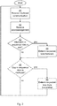
- Fig 2 is a flow chart illustrating embodiments of a method for enabling communication between the first communication device of the first substation and the second communication device of the second substation, as shown in Fig 1 .
- the method is performed in the edge computing device.
- the edge computing device receives multicast communication from the first communication device.
- the multicast communication is also intended for the second communication device.
- both the edge computing device and the second communication device subscribe to multicast communication from the first communication device.
- the multicast communication comprises a plurality of multicast packets, each multicast packet comprising a phasor value associated with the first substation.
- Each multicast packet further comprises a sequence number, which has a very long repeat time, essentially making the sequence number unique for all practical purposes.
- Each multicast packet can be an IP packet.
- the first communication device timestamps each packet just before transmission and the edge computing device timestamps each packet just after receiving the packet.
- the clocks are synchronised between the first communication device and the edge computing device, uplink communication latency between the first communication device and the edge computing device can be computed.
- the edge computing device receives an acknowledgement (also known as an ACK) from the second communication device.
- the acknowledgement comprising a plurality of sequence numbers.
- the sequence numbers respectively pertain to the n number of most recently received multicast packets that the second communication device has received from the first communication device, where n is any integer greater than 1.
- the acknowledgement is also transmitted to the first communication device.
- the number of sequence numbers in the ACK is configurable but is always greater than one, except for the first ACK, when only one packet has been received by the second communication device from the first communication device.
- the second communication device transmits an ACK for each successfully received (multicast) packet from the first communication device.
- the second communication device timestamps each ACK just before transmission and the edge computing device timestamps each ACK just after receiving the ACK.
- the edge computing device timestamps each ACK just after receiving the ACK.
- the edge computing device evaluates whether there is a mismatch in the sequence numbers of the acknowledgment, when compared with the sequence numbers of the received multicast communication. This can occur since multicast communication has occurred, whereby the edge computing device has also received the packets (and their respective sequence numbers) that was intended for the second communication device. Hence, any missing sequence number in the acknowledgement compared to the sequence numbers of the received multicast packets implies a packet loss to the second communication device.
- n 3
- the edge computing device has received packets with sequence numbers 105, 106, 107, 108, 109, 110.
- the most recent ACK received from the second communication device contains the sequence numbers 110, 109, 108. In this case, there is no mismatch, since the sequence numbers of the ack corresponds to the n last sequence numbers of packets received by the edge computing device. Consequently a packet loss has occurred in the communication from the first communication device to the second communication device.
- n again equals 3.
- the edge computing device has received packets with sequence numbers 105, 106, 107, 108, 109, 110.
- the most recent ACK received from the second communication device contains the sequence numbers 110, 109, 107.
- the ACK does not contain the sequence number 108 which is the sequence number of the third most recent packet received by the edge computing device.
- the method proceeds to a determine packet loss from ack step 44. Otherwise, the method proceeds to an optional conditional gap in sequence numbers in multicast step 45, or, if that step is not performed, the method repeats.
- the edge computing device determines that a packet loss has occurred to the second substation relay. In other words, there are one or more packets that the first communication device has transmitted that the second communication device never received. This information can be used for later action.
- the edge computing device evaluates whether there is a gap in the sequence numbers in packets of the multicast communication. This evaluation works as long as the sequence numbers follow a predetermined path, e.g. the sequence numbers can increase by one on each occasion.
- sequence numbers 232, 233, 234 and 235 are in sequence and do not have a gap while sequence number 232, 233 and 235 have a gap, in a missing sequence number 234.
- the method proceeds to an optional determine packet loss from transmitter step 46. Otherwise, the method repeats.
- the edge computing device determines that there is a packet loss from the first substation relay. This implies that the edge computing device 1 never received such packet(s).
- the packet loss can be detected when there is a packet loss from the first communication device to the second communication device. Since the edge computing device has received the missing packet for the mismatch to occur, the packet loss must have occurred somewhere between the base station for the first communication device and the second communication device, i.e. in downlink communication.
- the lost packet(s) never reached the edge computing device. In such a case, the packet loss must have occurred somewhere between the first communication device and edge computing device, i.e. in uplink communication.
- the edge computing device can trigger measures to reduce the effect of the packet loss. For instance, transmission power can be increased or the frequency of packets (containing the phasors) can be increased to reduce the impact of any one lost packet.
- the packet loss can be detected if the packet loss occurs in the uplink communication or downlink communication. This allows measures to be targeted to better mitigate the effects of the packet loss.
- FIG 3 is a schematic diagram illustrating components of an embodiment of the edge computing device 1 of Fig 1 .
- a processor 60 is provided using any combination of one or more of a suitable central processing unit (CPU), multiprocessor, microcontroller, digital signal processor (DSP), etc., capable of executing software instructions 67 stored in a memory 64, which can thus be a computer program product.
- the processor 60 could alternatively be implemented using an application specific integrated circuit (ASIC), field programmable gate array (FPGA), etc.
- the processor 60 can be configured to execute the method described with reference to Fig 2 above.
- the memory 64 can be any combination of random access memory (RAM) and/or read only memory (ROM).
- the memory 64 also comprises persistent storage, which, for example, can be any single one or combination of magnetic memory, optical memory, solid-state memory or even remotely mounted memory.
- the software instructions 67 can be in the form of one of several software applications which are executable by the processor 60.
- a data memory 66 is also provided for reading and/or storing data during execution of software instructions in the processor 60.
- the data memory 66 can be any combination of RAM and/or ROM.
- the edge computing device 1 further comprises an I/O interface 62 for communicating with other external entities.
- the I/O interface 62 also includes a user interface.
- edge computing device 1 Other components of the edge computing device 1 are omitted in order not to obscure the concepts presented herein.
- Fig 4 shows one example of a computer program product 90 comprising computer readable means.
- a computer program 91 can be stored, which computer program can cause a processor to execute a method according to embodiments described herein.
- the computer program product is an optical disc, such as a CD (compact disc) or a DVD (digital versatile disc) or a Blu-Ray disc.
- the computer program product could also be embodied in a memory of a device, such as the computer program product 64 of Fig 3 .
- the computer program 91 is here schematically shown as a track on the depicted optical disk, the computer program can be stored in any way which is suitable for the computer program product, such as a removable solid state memory, e.g. a Universal Serial Bus (USB) drive.
- USB Universal Serial Bus
Landscapes
- Engineering & Computer Science (AREA)
- Computer Networks & Wireless Communication (AREA)
- Signal Processing (AREA)
- Power Engineering (AREA)
- Multimedia (AREA)
- Computer Security & Cryptography (AREA)
- Mobile Radio Communication Systems (AREA)
Abstract
Description
- The invention relates to a method, an edge computing device, a computer program and a computer program product for enabling communication between a first communication device of a first substation and a second communication device of a second substation, the first substation and the second substation being connected to a power transmission line.
- Protective IEDs (Intelligent Electronic Devices), such as relays for line differential protection, currently use point to point wired communication when installed in different substations. The wired communication is reliable, but can be expensive to deploy and is not scalable.
- The cost can be reduced if the wired communication is replaced by utilizing the readily available communication infrastructure such as public cellular networks, enhancing flexibility and scalability while reducing cost.
- However, current structures of cellular communication networks are not sufficiently reliable to be used for critical applications such as line differential protection.
- It is an object to improve ability to detect lost packets when cellular communication networks are used for communication of phasor values.
- According to a first aspect, it is provided a method for enabling communication between a first communication device of a first substation and a second communication device of a second substation. The first substation and the second substation are connected to a power transmission line. The method is performed in an edge computing device and comprises the steps of: receiving multicast communication from the first communication device, the multicast communication also being intended for the second communication device, wherein the multicast communication comprising a plurality of multicast packets, and each multicast packet comprises a phasor value associated with the first substation and a sequence number; receiving an acknowledgement from the second communication device, the acknowledgement comprising a plurality of sequence numbers of the most recently received multicast packets, that the second communication device has received from the first communication device; and determining a packet loss to the second communication device when there is a mismatch between the sequence numbers of the acknowledgment, when compared with the sequence numbers of the received multicast communication.
- The method may further comprise the step of: determining a packet loss from the first communication device when there is a gap in the sequence numbers in packets of the multicast communication.
- Each multicast packet may be transmission timestamped by the first communication device, in which case the step of receiving multicast communication comprises receipt timestamping each received multicast packet.
- Each acknowledgement may be transmission timestamped by the second communication device, in which case the step of receiving an acknowledgement comprises receipt timestamping each received acknowledgement.
- The first substation and the second substation may be electrical substations for managing electrical power transfer over the power transmission line.
- According to a second aspect, it is provided an edge computing device for enabling communication between a first communication device of a first substation and a second communication device of a second substation. The first substation and the second substation are connected to a power transmission line. The edge computing device comprises: a processor; and a memory storing instructions that, when executed by the processor, cause the edge computing device to: receive multicast communication from the first communication device, the multicast communication also being intended for the second communication device, wherein the multicast communication comprising a plurality of multicast packets, and each multicast packet comprises a phasor value associated with the first substation and a sequence number; receive an acknowledgement from the second communication device, the acknowledgement comprising a plurality of sequence numbers of the most recently received multicast packets, that the second communication device has received from the first communication device; and determine a packet loss to the second communication device when there is a mismatch between the sequence numbers of the acknowledgment, when compared with the sequence numbers of the received multicast communication.
- The edge computing device may further comprise instructions that, when executed by the processor, cause the edge computing device to: determine a packet loss from the first communication device when there is a gap in the sequence numbers in packets of the multicast communication.
- Each multicast packet may be transmission timestamped by the first communication device, in which case the instructions to receive multicast communication comprise instructions that, when executed by the processor, cause the edge computing device to receipt timestamp each received multicast packet.
- Each acknowledgement may be transmission timestamped by the second communication device, in which case the instructions to receive an acknowledgement comprise instructions that, when executed by the processor, cause the edge computing device to receipt timestamping each received acknowledgement.
- The first substation and the second substation may be electrical substations for managing electrical power transfer over the power transmission line.
- According to a third aspect, it is provided a computer program for enabling communication between a first communication device of a first substation and a second communication device of a second substation, the first substation and the second substation being connected to a power transmission line. The computer program comprising computer program code which, when run on a edge computing device causes the edge computing device to: receive multicast communication from the first communication device, the multicast communication also being intended for the second communication device, wherein the multicast communication comprising a plurality of multicast packets, and each multicast packet comprises a phasor value associated with the first substation and a sequence number; receive an acknowledgement from the second communication device, the acknowledgement comprising a plurality of sequence numbers of the most recently received multicast packets, that the second communication device has received from the first communication device; and determine a packet loss to the second communication device when there is a mismatch between the sequence numbers of the acknowledgment, when compared with the sequence numbers of the received multicast communication.
- According to a fourth aspect, it is provided a computer program product comprising a computer program according to the third aspect and a computer readable means on which the computer program is stored.
- Generally, all terms used in the claims are to be interpreted according to their ordinary meaning in the technical field, unless explicitly defined otherwise herein. All references to "a/an/the element, apparatus, component, means, step, etc." are to be interpreted openly as referring to at least one instance of the element, apparatus, component, means, step, etc., unless explicitly stated otherwise. The steps of any method disclosed herein do not have to be performed in the exact order disclosed, unless explicitly stated.
- The invention is now described, by way of example, with reference to the accompanying drawings, in which:
-
Fig 1 is a schematic drawing illustrating an environment in which embodiments presented herein can be applied; -
Fig 2 is a flow chart illustrating embodiments of a method for enabling communication between a first communication device of a first substation and a second communication device of a second substation, as shown in Fig i; -
Fig 3 is a schematic diagram illustrating components of an embodiment of the edge computing device ofFig 1 ; and -
Fig 4 shows one example of a computer program product comprising computer readable means. - The invention will now be described more fully hereinafter with reference to the accompanying drawings, in which certain embodiments of the invention are shown. This invention may, however, be embodied in many different forms and should not be construed as limited to the embodiments set forth herein; rather, these embodiments are provided by way of example so that this disclosure will be thorough and complete, and will fully convey the scope of the invention to those skilled in the art. Like numbers refer to like elements throughout the description.
- Embodiments presented herein are based on the introduction of including a plurality of latest received sequence numbers in acknowledgements (ACKs) sent as a response to received data packets. The ACKs are checked in an edge computing device which receives both the data packets and the ACKs. By checking the plurality of latest received sequence numbers against the received data packets, any data packets which have not been received can be detected.
-
Fig 1 is a schematic drawing illustrating an environment in which embodiments presented herein can be applied. Apower transmission line 10 is used to transfer AC (Alternating Current) power in an electric grid. Thetransmission line 10 can transfer power in either direction. Thetransmission line 10 comprises separate cables for separate phases, e.g. three phases. The transmission is primarily a medium voltage (MV) transmission. For the purposes of the present disclosure, medium voltage (MV) relates to voltages higher than 1 kV AC and lower than 72 kV AC. - There is a
first substation 12a and asecond substation 12b. Each of thesubstations transmission line 10. Both the first substation and the second substation are electrical substations for managing electrical power transfer over the power transmission line. For instance, the substations can comprise components for power conversion and/or power distribution. The measurements relate to voltages and/or currents and are expressed as phasors. By communicating the phasors between the twosubstations sub-stations - A
base station 2 of a cellular network provides cellular network coverage for the twosubstations base station 2 is shown here,multiple base stations 2 are often deployed to provide sufficient coverage. Thefirst substation 12a comprises afirst communication device 11a and thesecond substation 12b comprises asecond communication device 11b. Thebase station 2, together with other base stations, form part of a Radio Access Network (RAN). - Each one of the
first communication device 11a and thesecond communication device 11b comprise hardware and software to allow the second communication device to act as a cellular communication terminal, also known as User Equipment (UE), for communication with thebase station 2 using a cellular communication network. The cellular communication network can e.g. comply with any one or a combination of LTE (Long Term Evolution), next generation mobile networks (fifth generation, 5G), UMTS (Universal Mobile Telecommunications System) utilising W-CDMA (Wideband Code Division Multiplex), CDMA2000 (Code Division Multiple Access 2000), or any other current or future wireless network, as long as the principles described hereinafter are applicable. - Wireless cellular communication is prone to interference from other devices and sources operating in the same frequency bands in nearby cells. Moreover, attenuation occurs in extreme weather conditions and fading occurs due to obstructions. In order to use cellular communication for purposes of line differential analysis of a transmission line, both desired latency and reliability of the communication should be ensured. This implies that better granularity in channel supervision is needed in order to determine if a packet has been lost in uplink (communication device to base station) or downlink (base station to communication) direction compared with the prior art. This is achieved by providing, in each acknowledgement, indication of not only the last successfully received packet, but the last n successfully received packets. More details of this solution are provided below.
- The
first communication device 11a can senduplink communication 3a to thebase station 2 and receivedownlink communication 4a from thebase station 2. Analogously, thesecond communication device 11b can senduplink communication 3b to thebase station 2 and receivedownlink communication 4b from thebase station 2. In other words,uplink communication communication devices base station 2 anddownlink communication base station 2 to thecommunication devices communication devices - In close proximity to the
base station 2, there is anedge computing device 1. By providing theedge computing device 1 by thebase station 2, rather than in a central location for the whole network, latency is significantly reduced. Moreover, bandwidth requirements for inter network communication is reduced. Theedge computing device 1 utilises what is called multi-access edge computing (MEC). MEC is a cloud computing capability at the edge of the RAN that offers storage and computational resources at the edge, for running low latency applications. - As explained in more detail below, the
edge computing device 1 is used to detect communication errors between thefirst communication device 11a and thesecond communication device 11b. - It is to be noted that more substations and respective communication devices can be provided than those shown in
Fig 1 . -
Fig 2 is a flow chart illustrating embodiments of a method for enabling communication between the first communication device of the first substation and the second communication device of the second substation, as shown inFig 1 . The method is performed in the edge computing device. - In a receive
multicast communication step 40, the edge computing device receives multicast communication from the first communication device. The multicast communication is also intended for the second communication device. In other words, both the edge computing device and the second communication device subscribe to multicast communication from the first communication device. The multicast communication comprises a plurality of multicast packets, each multicast packet comprising a phasor value associated with the first substation. Each multicast packet further comprises a sequence number, which has a very long repeat time, essentially making the sequence number unique for all practical purposes. Each multicast packet can be an IP packet. - Optionally, the first communication device timestamps each packet just before transmission and the edge computing device timestamps each packet just after receiving the packet. In this way, as long as the clocks are synchronised between the first communication device and the edge computing device, uplink communication latency between the first communication device and the edge computing device can be computed.
- In a receive
acknowledgement step 42, the edge computing device receives an acknowledgement (also known as an ACK) from the second communication device. The acknowledgement comprising a plurality of sequence numbers. The sequence numbers respectively pertain to the n number of most recently received multicast packets that the second communication device has received from the first communication device, where n is any integer greater than 1. The acknowledgement is also transmitted to the first communication device. The number of sequence numbers in the ACK is configurable but is always greater than one, except for the first ACK, when only one packet has been received by the second communication device from the first communication device. The second communication device transmits an ACK for each successfully received (multicast) packet from the first communication device. - Optionally, the second communication device timestamps each ACK just before transmission and the edge computing device timestamps each ACK just after receiving the ACK. In this way, as long as the clocks are synchronised between the second communication device and the edge computing device, uplink communication latency between the second communication device and the edge computing device can be computed.
- In a conditional mismatch in sequence numbers in
ack step 43, the edge computing device evaluates whether there is a mismatch in the sequence numbers of the acknowledgment, when compared with the sequence numbers of the received multicast communication. This can occur since multicast communication has occurred, whereby the edge computing device has also received the packets (and their respective sequence numbers) that was intended for the second communication device. Hence, any missing sequence number in the acknowledgement compared to the sequence numbers of the received multicast packets implies a packet loss to the second communication device. - This will mismatch determination will now be illustrated with a couple of examples.
- In a first example, n equals 3. The edge computing device has received packets with sequence numbers 105, 106, 107, 108, 109, 110. The most recent ACK received from the second communication device contains the sequence numbers 110, 109, 108. In this case, there is no mismatch, since the sequence numbers of the ack corresponds to the n last sequence numbers of packets received by the edge computing device. Consequently a packet loss has occurred in the communication from the first communication device to the second communication device.
- In a second example, n again equals 3. The edge computing device has received packets with sequence numbers 105, 106, 107, 108, 109, 110. The most recent ACK received from the second communication device contains the sequence numbers 110, 109, 107. In this case, there is a mismatch, since the sequence numbers of the ack do not corresponds to the n last sequence numbers of packets received by the edge computing device. The ACK does not contain the sequence number 108 which is the sequence number of the third most recent packet received by the edge computing device.
- If there is a mismatch, the method proceeds to a determine packet loss from ack
step 44. Otherwise, the method proceeds to an optional conditional gap in sequence numbers inmulticast step 45, or, if that step is not performed, the method repeats. - In the determine packet loss from ack
step 44, the edge computing device determining that a packet loss has occurred to the second substation relay. In other words, there are one or more packets that the first communication device has transmitted that the second communication device never received. This information can be used for later action. - In an optional conditional gap in sequence numbers in
multicast step 45, the edge computing device evaluates whether there is a gap in the sequence numbers in packets of the multicast communication. This evaluation works as long as the sequence numbers follow a predetermined path, e.g. the sequence numbers can increase by one on each occasion. In one example, sequence numbers 232, 233, 234 and 235 are in sequence and do not have a gap while sequence number 232, 233 and 235 have a gap, in a missing sequence number 234. - If there is a gap, the method proceeds to an optional determine packet loss from
transmitter step 46. Otherwise, the method repeats. - In the optional determine packet loss from
transmitter step 46, the edge computing device determines that there is a packet loss from the first substation relay. This implies that theedge computing device 1 never received such packet(s). - It is to be noted that while the method described above concerns communication from the first communication device to the second communication device, the same type of communication can occur in the other direction, from the second communication device to the first communication device.
- Using the plurality of sequence numbers of the acknowledgement described above, it can be detected when there is a packet loss from the first communication device to the second communication device. Since the edge computing device has received the missing packet for the mismatch to occur, the packet loss must have occurred somewhere between the base station for the first communication device and the second communication device, i.e. in downlink communication.
- When packet loss is detected in the edge computing device due to a gap in sequence numbers of the packets of the multicast communication, the lost packet(s) never reached the edge computing device. In such a case, the packet loss must have occurred somewhere between the first communication device and edge computing device, i.e. in uplink communication.
- When packet losses occur, the edge computing device can trigger measures to reduce the effect of the packet loss. For instance, transmission power can be increased or the frequency of packets (containing the phasors) can be increased to reduce the impact of any one lost packet.
- Using this method, reliability packet loss detection is greatly increased, allowing the edge computing device to take appropriate measures if and when packet losses do occur.
- Additionally, it can be detected if the packet loss occurs in the uplink communication or downlink communication. This allows measures to be targeted to better mitigate the effects of the packet loss.
-
Fig 3 is a schematic diagram illustrating components of an embodiment of theedge computing device 1 ofFig 1 . Aprocessor 60 is provided using any combination of one or more of a suitable central processing unit (CPU), multiprocessor, microcontroller, digital signal processor (DSP), etc., capable of executingsoftware instructions 67 stored in amemory 64, which can thus be a computer program product. Theprocessor 60 could alternatively be implemented using an application specific integrated circuit (ASIC), field programmable gate array (FPGA), etc. Theprocessor 60 can be configured to execute the method described with reference toFig 2 above. - The
memory 64 can be any combination of random access memory (RAM) and/or read only memory (ROM). Thememory 64 also comprises persistent storage, which, for example, can be any single one or combination of magnetic memory, optical memory, solid-state memory or even remotely mounted memory. Thesoftware instructions 67 can be in the form of one of several software applications which are executable by theprocessor 60. - A
data memory 66 is also provided for reading and/or storing data during execution of software instructions in theprocessor 60. Thedata memory 66 can be any combination of RAM and/or ROM. - The
edge computing device 1 further comprises an I/O interface 62 for communicating with other external entities. Optionally, the I/O interface 62 also includes a user interface. - Other components of the
edge computing device 1 are omitted in order not to obscure the concepts presented herein. -
Fig 4 shows one example of acomputer program product 90 comprising computer readable means. On this computer readable means, acomputer program 91 can be stored, which computer program can cause a processor to execute a method according to embodiments described herein. In this example, the computer program product is an optical disc, such as a CD (compact disc) or a DVD (digital versatile disc) or a Blu-Ray disc. As explained above, the computer program product could also be embodied in a memory of a device, such as thecomputer program product 64 ofFig 3 . While thecomputer program 91 is here schematically shown as a track on the depicted optical disk, the computer program can be stored in any way which is suitable for the computer program product, such as a removable solid state memory, e.g. a Universal Serial Bus (USB) drive. - The invention has mainly been described above with reference to a few embodiments. However, as is readily appreciated by a person skilled in the art, other embodiments than the ones disclosed above are equally possible within the scope of the invention, as defined by the appended patent claims.
Claims (12)
- A method for enabling communication between a first communication device (11a) of a first substation (12a) and a second communication device (11b) of a second substation (12b), the first substation (12a) and the second substation (12b) being connected to a power transmission line (10), the method being performed in an edge computing device (1) and comprising the steps of:receiving (40) multicast communication (3a) from the first communication device (11a), the multicast communication (3a) also being intended for the second communication device (11b), wherein the multicast communication (3a) comprising a plurality of multicast packets, and each multicast packet comprises a phasor value associated with the first substation (12a) and a sequence number;receiving (42) an acknowledgement (3b) from the second communication device (11b), the acknowledgement (3b) comprising a plurality of sequence numbers of the most recently received multicast packets, that the second communication device (11b) has received from the first communication device (11b); anddetermining (44) a packet loss to the second communication device (12b) when there is a mismatch between the sequence numbers of the acknowledgment, when compared with the sequence numbers of the received multicast communication.
- The method according to claim 1, further comprising the step of:
determining (46) a packet loss from the first communication device (11a) when there is a gap in the sequence numbers in packets of the multicast communication. - The method according to claim 1 or 2, wherein each multicast packet is transmission timestamped by the first communication device (11a), and wherein the step of receiving (40) multicast communication comprises receipt timestamping each received multicast packet.
- The method according to any one of the preceding claims, wherein each acknowledgement is transmission timestamped by the second communication device (11a), and wherein the step of receiving (42) an acknowledgement comprises receipt timestamping each received acknowledgement.
- The method according to any one of the preceding claims, wherein the first substation (12a) and the second substation (12b) are electrical substations for managing electrical power transfer over the power transmission line (10).
- An edge computing device (1) for enabling communication between a first communication device (11a) of a first substation (12a) and a second communication device (11b) of a second substation (12b), the first substation (12a) and the second substation (12b) being connected to a power transmission line (10), the edge computing device (1) comprising:a processor (60); anda memory (64) storing instructions (67) that, when executed by the processor, cause the edge computing device (1) to:receive multicast communication (3a) from the first communication device (11a), the multicast communication (3a) also being intended for the second communication device (11b), wherein the multicast communication (3a) comprising a plurality of multicast packets, and each multicast packet comprises a phasor value associated with the first substation (12a) and a sequence number; andreceive an acknowledgement (3b) from the second communication device (11b), the acknowledgement (3b) comprising a plurality of sequence numbers of the most recently received multicast packets, that the second communication device (11b) has received from the first communication device (11b);determine a packet loss to the second communication device (12b) when there is a mismatch between the sequence numbers of the acknowledgment, when compared with the sequence numbers of the received multicast communication.
- The edge computing device (1) according to claim 6, further comprising instructions (67) that, when executed by the processor, cause the edge computing device (1) to:
determine a packet loss from the first communication device (11a) when there is a gap in the sequence numbers in packets of the multicast communication. - The edge computing device (1) according to claim 6 or 7, wherein each multicast packet is transmission timestamped by the first communication device (11a), and wherein the instructions to receive multicast communication comprise instructions (67) that, when executed by the processor, cause the edge computing device (1) to receipt timestamp each received multicast packet.
- The edge computing device (1) according to any one of claims 6 to 8, wherein each acknowledgement is transmission timestamped by the second communication device (11a), and wherein the instructions to receive an acknowledgement comprise instructions (67) that, when executed by the processor, cause the edge computing device (1) to receipt timestamp each received acknowledgement.
- The edge computing device (1) according to any one of claims 6 to 9, wherein the first substation (12a) and the second substation (12b) are electrical substations for managing electrical power transfer over the power transmission line (10).
- A computer program (67, 91) for enabling communication between a first communication device (11a) of a first substation (12a) and a second communication device (11b) of a second substation (12b), the first substation (12a) and the second substation (12b) being connected to a power transmission line (10), the computer program comprising computer program code which, when run on a edge computing device (1) causes the edge computing device (1) to:receive multicast communication (3a) from the first communication device (11a), the multicast communication (3a) also being intended for the second communication device (11b), wherein the multicast communication (3a) comprising a plurality of multicast packets, and each multicast packet comprises a phasor value associated with the first substation (12a) and a sequence number;receive an acknowledgement (3b) from the second communication device (11b), the acknowledgement (3b) comprising a plurality of sequence numbers of the most recently received multicast packets, that the second communication device (11b) has received from the first communication device (11b); anddetermine a packet loss to the second communication device (12b) when there is a mismatch between the sequence numbers of the acknowledgment, when compared with the sequence numbers of the received multicast communication.
- A computer program product (64, 90) comprising a computer program according to claim 11 and a computer readable means on which the computer program is stored.
Priority Applications (4)
| Application Number | Priority Date | Filing Date | Title |
|---|---|---|---|
| EP18161410.8A EP3540910B1 (en) | 2018-03-13 | 2018-03-13 | Enabling communication between communication devices of substations |
| US16/975,065 US11546099B2 (en) | 2018-03-13 | 2019-02-22 | Enabling communication between a communication devices of a substations |
| PCT/EP2019/054411 WO2019174890A1 (en) | 2018-03-13 | 2019-02-22 | Enabling communication between a communication devices of a substations |
| CN201980018711.2A CN111869044B (en) | 2018-03-13 | 2019-02-22 | Realize communication between substation communication equipment |
Applications Claiming Priority (1)
| Application Number | Priority Date | Filing Date | Title |
|---|---|---|---|
| EP18161410.8A EP3540910B1 (en) | 2018-03-13 | 2018-03-13 | Enabling communication between communication devices of substations |
Publications (2)
| Publication Number | Publication Date |
|---|---|
| EP3540910A1 true EP3540910A1 (en) | 2019-09-18 |
| EP3540910B1 EP3540910B1 (en) | 2021-05-05 |
Family
ID=61628174
Family Applications (1)
| Application Number | Title | Priority Date | Filing Date |
|---|---|---|---|
| EP18161410.8A Active EP3540910B1 (en) | 2018-03-13 | 2018-03-13 | Enabling communication between communication devices of substations |
Country Status (4)
| Country | Link |
|---|---|
| US (1) | US11546099B2 (en) |
| EP (1) | EP3540910B1 (en) |
| CN (1) | CN111869044B (en) |
| WO (1) | WO2019174890A1 (en) |
Cited By (3)
| Publication number | Priority date | Publication date | Assignee | Title |
|---|---|---|---|---|
| CN110994798A (en) * | 2019-12-16 | 2020-04-10 | 深圳供电局有限公司 | Substation equipment monitoring system |
| CN112073326A (en) * | 2020-07-30 | 2020-12-11 | 许继集团有限公司 | Intelligent substation process layer network data flow control method |
| CN112564054A (en) * | 2020-11-18 | 2021-03-26 | 深圳供电局有限公司 | Transformer substation differential protection intelligent system based on 5G application |
Families Citing this family (2)
| Publication number | Priority date | Publication date | Assignee | Title |
|---|---|---|---|---|
| CN111327477A (en) * | 2020-02-28 | 2020-06-23 | 中国电力科学研究院有限公司 | A method and system for substation domain control and protection based on edge computing |
| CN112615434A (en) * | 2020-06-14 | 2021-04-06 | 石霜霜 | Data management method applied to edge computing and cloud computing and edge computing platform |
Citations (3)
| Publication number | Priority date | Publication date | Assignee | Title |
|---|---|---|---|---|
| US20120046891A1 (en) * | 2008-01-20 | 2012-02-23 | Yaney David S | Method and Apparatus for Communicating Power Distribution Event and Location |
| US20150035681A1 (en) * | 2013-08-01 | 2015-02-05 | Schweitzer Engineering Laboratories, Inc. | Point-to-Multipoint Polling in a Monitoring System for an Electric Power Distribution System |
| WO2017039493A1 (en) * | 2015-08-28 | 2017-03-09 | Telefonaktiebolaget Lm Ericsson (Publ) | Transmitting downlink signals |
Family Cites Families (14)
| Publication number | Priority date | Publication date | Assignee | Title |
|---|---|---|---|---|
| US7522588B2 (en) * | 2002-05-13 | 2009-04-21 | Qualcomm Incorporated | System and method for reference data processing in network assisted position determination |
| US8908700B2 (en) * | 2007-09-07 | 2014-12-09 | Citrix Systems, Inc. | Systems and methods for bridging a WAN accelerator with a security gateway |
| US8200546B2 (en) * | 2008-01-31 | 2012-06-12 | At&T Intellectual Property I, L.P. | System and method for distributing media content |
| CA2725065A1 (en) * | 2008-05-20 | 2009-11-26 | Live Meters, Inc. | Remote monitoring and control system comprising mesh and time synchronization technology |
| EP2211479A1 (en) * | 2009-01-15 | 2010-07-28 | ABB Technology AG | Communication method and system |
| CN101815249B (en) * | 2009-02-23 | 2013-01-02 | 中国电信股份有限公司 | Method and system for realizing continuity of mobile network PTT service |
| US8743716B2 (en) * | 2011-02-04 | 2014-06-03 | General Electric Company | Systems, methods, and apparatus for identifying invalid nodes within a mesh network |
| US20130274936A1 (en) * | 2012-04-15 | 2013-10-17 | Swan, Llc | Broadcast energy demand systems and methods |
| JP2013229662A (en) * | 2012-04-24 | 2013-11-07 | Mitsubishi Electric Corp | Mobile ip network handover system, mobile packet processing device, and ground packet processing device |
| EP2670083B1 (en) * | 2012-05-28 | 2015-05-06 | Itron, Inc. | Efficient multicast in a smart grid |
| US9059929B2 (en) * | 2012-06-15 | 2015-06-16 | Cisco Technology, Inc. | Reliable on-demand distributed data management in a sensor-actuator fabric |
| US9900169B2 (en) * | 2015-03-18 | 2018-02-20 | Cisco Technology, Inc. | Reliable multicast in low-power and lossy networks |
| WO2016181685A1 (en) * | 2015-05-08 | 2016-11-17 | ソニー株式会社 | Transmission control device, transmission control method, reception control device and reception control method |
| JP6604076B2 (en) * | 2015-07-29 | 2019-11-13 | 東京電力ホールディングス株式会社 | Supervisory control system |
-
2018
- 2018-03-13 EP EP18161410.8A patent/EP3540910B1/en active Active
-
2019
- 2019-02-22 US US16/975,065 patent/US11546099B2/en active Active
- 2019-02-22 WO PCT/EP2019/054411 patent/WO2019174890A1/en not_active Ceased
- 2019-02-22 CN CN201980018711.2A patent/CN111869044B/en active Active
Patent Citations (3)
| Publication number | Priority date | Publication date | Assignee | Title |
|---|---|---|---|---|
| US20120046891A1 (en) * | 2008-01-20 | 2012-02-23 | Yaney David S | Method and Apparatus for Communicating Power Distribution Event and Location |
| US20150035681A1 (en) * | 2013-08-01 | 2015-02-05 | Schweitzer Engineering Laboratories, Inc. | Point-to-Multipoint Polling in a Monitoring System for an Electric Power Distribution System |
| WO2017039493A1 (en) * | 2015-08-28 | 2017-03-09 | Telefonaktiebolaget Lm Ericsson (Publ) | Transmitting downlink signals |
Cited By (4)
| Publication number | Priority date | Publication date | Assignee | Title |
|---|---|---|---|---|
| CN110994798A (en) * | 2019-12-16 | 2020-04-10 | 深圳供电局有限公司 | Substation equipment monitoring system |
| CN112073326A (en) * | 2020-07-30 | 2020-12-11 | 许继集团有限公司 | Intelligent substation process layer network data flow control method |
| CN112073326B (en) * | 2020-07-30 | 2023-05-12 | 许继集团有限公司 | Intelligent substation process layer network data flow control method |
| CN112564054A (en) * | 2020-11-18 | 2021-03-26 | 深圳供电局有限公司 | Transformer substation differential protection intelligent system based on 5G application |
Also Published As
| Publication number | Publication date |
|---|---|
| WO2019174890A1 (en) | 2019-09-19 |
| US20210014648A1 (en) | 2021-01-14 |
| US11546099B2 (en) | 2023-01-03 |
| CN111869044B (en) | 2024-06-11 |
| CN111869044A (en) | 2020-10-30 |
| EP3540910B1 (en) | 2021-05-05 |
Similar Documents
| Publication | Publication Date | Title |
|---|---|---|
| US11546099B2 (en) | Enabling communication between a communication devices of a substations | |
| US10999761B2 (en) | Methods to determine a hybrid automatic repeat request acknowledgement (HARQ-ACK) codebook in new radio (NR) systems | |
| US11019682B2 (en) | Methods to multiplex control information in accordance with multi-slot transmissions in new radio (NR) systems | |
| US20220368390A1 (en) | Size determination for channel state information (csi) part one and part two transmission of csi report | |
| US10784947B2 (en) | Methods of beam management and beam selection based on measurement reporting in new radio (NR) systems | |
| US12309654B2 (en) | Generation node-B (GNB), user equipment (UE) and methods for handover in new radio (NR) systems | |
| US10638341B2 (en) | Wireless environment information collection system and method | |
| CN111886819B (en) | Intelligent electronic device and communication method including cellular radio module | |
| CN109673021B (en) | Service delay determining method | |
| Ghanem et al. | Challenges and promises of 5G for smart grid teleprotection applications | |
| WO2018084985A1 (en) | User equipment (ue), evolved node-b (enb) and methods for signal power measurement and reference signal transmission in new radio (nr) systems | |
| US20190273578A1 (en) | Methods of adaptive transmission in low latency scenarios in new radio (nr) systems | |
| US20140080486A1 (en) | Wireless communications system, communication apparatus, and wireless communications method | |
| CN114978817A (en) | Communication of channel estimates in a radio access network | |
| Horsmanheimo et al. | Feasibility study of utilizing mobile communications for smart grid applications in urban area | |
| Abdrabou et al. | Considerations for packet delivery reliability over polling-based wireless networks in smart grids | |
| Khan et al. | Differential protection of microgrids over a WiMAX network | |
| Moxley et al. | Updated transmission line protection communications | |
| CN116508351B (en) | Limiting the impact of cellular networks on latency in industrial automation systems | |
| Raghuraman et al. | URLLC-Aided System Protection in Smart Electric Power Distribution Systems | |
| Normoyle et al. | Sentinel, fast detection of faulted transmission line arresters | |
| EP4161136A1 (en) | Increased uplink capacity for campus networks via tdd interference mitigation | |
| CN120956588A (en) | A method for data interaction between power grid, cloud, and edge |
Legal Events
| Date | Code | Title | Description |
|---|---|---|---|
| PUAI | Public reference made under article 153(3) epc to a published international application that has entered the european phase |
Free format text: ORIGINAL CODE: 0009012 |
|
| STAA | Information on the status of an ep patent application or granted ep patent |
Free format text: STATUS: THE APPLICATION HAS BEEN PUBLISHED |
|
| AK | Designated contracting states |
Kind code of ref document: A1 Designated state(s): AL AT BE BG CH CY CZ DE DK EE ES FI FR GB GR HR HU IE IS IT LI LT LU LV MC MK MT NL NO PL PT RO RS SE SI SK SM TR |
|
| AX | Request for extension of the european patent |
Extension state: BA ME |
|
| STAA | Information on the status of an ep patent application or granted ep patent |
Free format text: STATUS: REQUEST FOR EXAMINATION WAS MADE |
|
| 17P | Request for examination filed |
Effective date: 20191112 |
|
| RBV | Designated contracting states (corrected) |
Designated state(s): AL AT BE BG CH CY CZ DE DK EE ES FI FR GB GR HR HU IE IS IT LI LT LU LV MC MK MT NL NO PL PT RO RS SE SI SK SM TR |
|
| STAA | Information on the status of an ep patent application or granted ep patent |
Free format text: STATUS: EXAMINATION IS IN PROGRESS |
|
| 17Q | First examination report despatched |
Effective date: 20200324 |
|
| GRAP | Despatch of communication of intention to grant a patent |
Free format text: ORIGINAL CODE: EPIDOSNIGR1 |
|
| STAA | Information on the status of an ep patent application or granted ep patent |
Free format text: STATUS: GRANT OF PATENT IS INTENDED |
|
| RIC1 | Information provided on ipc code assigned before grant |
Ipc: H04L 1/16 20060101ALI20201102BHEP Ipc: H02J 13/00 20060101AFI20201102BHEP Ipc: H04L 1/18 20060101ALI20201102BHEP |
|
| INTG | Intention to grant announced |
Effective date: 20201124 |
|
| GRAS | Grant fee paid |
Free format text: ORIGINAL CODE: EPIDOSNIGR3 |
|
| GRAA | (expected) grant |
Free format text: ORIGINAL CODE: 0009210 |
|
| STAA | Information on the status of an ep patent application or granted ep patent |
Free format text: STATUS: THE PATENT HAS BEEN GRANTED |
|
| RAP3 | Party data changed (applicant data changed or rights of an application transferred) |
Owner name: ABB SCHWEIZ AG |
|
| AK | Designated contracting states |
Kind code of ref document: B1 Designated state(s): AL AT BE BG CH CY CZ DE DK EE ES FI FR GB GR HR HU IE IS IT LI LT LU LV MC MK MT NL NO PL PT RO RS SE SI SK SM TR |
|
| REG | Reference to a national code |
Ref country code: GB Ref legal event code: FG4D |
|
| REG | Reference to a national code |
Ref country code: CH Ref legal event code: EP |
|
| REG | Reference to a national code |
Ref country code: AT Ref legal event code: REF Ref document number: 1391047 Country of ref document: AT Kind code of ref document: T Effective date: 20210515 |
|
| REG | Reference to a national code |
Ref country code: DE Ref legal event code: R096 Ref document number: 602018016440 Country of ref document: DE |
|
| REG | Reference to a national code |
Ref country code: IE Ref legal event code: FG4D |
|
| REG | Reference to a national code |
Ref country code: FI Ref legal event code: FGE |
|
| REG | Reference to a national code |
Ref country code: LT Ref legal event code: MG9D |
|
| REG | Reference to a national code |
Ref country code: AT Ref legal event code: MK05 Ref document number: 1391047 Country of ref document: AT Kind code of ref document: T Effective date: 20210505 |
|
| PG25 | Lapsed in a contracting state [announced via postgrant information from national office to epo] |
Ref country code: LT Free format text: LAPSE BECAUSE OF FAILURE TO SUBMIT A TRANSLATION OF THE DESCRIPTION OR TO PAY THE FEE WITHIN THE PRESCRIBED TIME-LIMIT Effective date: 20210505 Ref country code: HR Free format text: LAPSE BECAUSE OF FAILURE TO SUBMIT A TRANSLATION OF THE DESCRIPTION OR TO PAY THE FEE WITHIN THE PRESCRIBED TIME-LIMIT Effective date: 20210505 Ref country code: AT Free format text: LAPSE BECAUSE OF FAILURE TO SUBMIT A TRANSLATION OF THE DESCRIPTION OR TO PAY THE FEE WITHIN THE PRESCRIBED TIME-LIMIT Effective date: 20210505 Ref country code: BG Free format text: LAPSE BECAUSE OF FAILURE TO SUBMIT A TRANSLATION OF THE DESCRIPTION OR TO PAY THE FEE WITHIN THE PRESCRIBED TIME-LIMIT Effective date: 20210805 |
|
| PG25 | Lapsed in a contracting state [announced via postgrant information from national office to epo] |
Ref country code: GR Free format text: LAPSE BECAUSE OF FAILURE TO SUBMIT A TRANSLATION OF THE DESCRIPTION OR TO PAY THE FEE WITHIN THE PRESCRIBED TIME-LIMIT Effective date: 20210806 Ref country code: IS Free format text: LAPSE BECAUSE OF FAILURE TO SUBMIT A TRANSLATION OF THE DESCRIPTION OR TO PAY THE FEE WITHIN THE PRESCRIBED TIME-LIMIT Effective date: 20210905 Ref country code: PT Free format text: LAPSE BECAUSE OF FAILURE TO SUBMIT A TRANSLATION OF THE DESCRIPTION OR TO PAY THE FEE WITHIN THE PRESCRIBED TIME-LIMIT Effective date: 20210906 Ref country code: PL Free format text: LAPSE BECAUSE OF FAILURE TO SUBMIT A TRANSLATION OF THE DESCRIPTION OR TO PAY THE FEE WITHIN THE PRESCRIBED TIME-LIMIT Effective date: 20210505 Ref country code: NO Free format text: LAPSE BECAUSE OF FAILURE TO SUBMIT A TRANSLATION OF THE DESCRIPTION OR TO PAY THE FEE WITHIN THE PRESCRIBED TIME-LIMIT Effective date: 20210805 Ref country code: LV Free format text: LAPSE BECAUSE OF FAILURE TO SUBMIT A TRANSLATION OF THE DESCRIPTION OR TO PAY THE FEE WITHIN THE PRESCRIBED TIME-LIMIT Effective date: 20210505 Ref country code: RS Free format text: LAPSE BECAUSE OF FAILURE TO SUBMIT A TRANSLATION OF THE DESCRIPTION OR TO PAY THE FEE WITHIN THE PRESCRIBED TIME-LIMIT Effective date: 20210505 Ref country code: SE Free format text: LAPSE BECAUSE OF FAILURE TO SUBMIT A TRANSLATION OF THE DESCRIPTION OR TO PAY THE FEE WITHIN THE PRESCRIBED TIME-LIMIT Effective date: 20210505 |
|
| REG | Reference to a national code |
Ref country code: NL Ref legal event code: MP Effective date: 20210505 |
|
| PG25 | Lapsed in a contracting state [announced via postgrant information from national office to epo] |
Ref country code: NL Free format text: LAPSE BECAUSE OF FAILURE TO SUBMIT A TRANSLATION OF THE DESCRIPTION OR TO PAY THE FEE WITHIN THE PRESCRIBED TIME-LIMIT Effective date: 20210505 |
|
| PG25 | Lapsed in a contracting state [announced via postgrant information from national office to epo] |
Ref country code: RO Free format text: LAPSE BECAUSE OF FAILURE TO SUBMIT A TRANSLATION OF THE DESCRIPTION OR TO PAY THE FEE WITHIN THE PRESCRIBED TIME-LIMIT Effective date: 20210505 Ref country code: CZ Free format text: LAPSE BECAUSE OF FAILURE TO SUBMIT A TRANSLATION OF THE DESCRIPTION OR TO PAY THE FEE WITHIN THE PRESCRIBED TIME-LIMIT Effective date: 20210505 Ref country code: DK Free format text: LAPSE BECAUSE OF FAILURE TO SUBMIT A TRANSLATION OF THE DESCRIPTION OR TO PAY THE FEE WITHIN THE PRESCRIBED TIME-LIMIT Effective date: 20210505 Ref country code: SM Free format text: LAPSE BECAUSE OF FAILURE TO SUBMIT A TRANSLATION OF THE DESCRIPTION OR TO PAY THE FEE WITHIN THE PRESCRIBED TIME-LIMIT Effective date: 20210505 Ref country code: SK Free format text: LAPSE BECAUSE OF FAILURE TO SUBMIT A TRANSLATION OF THE DESCRIPTION OR TO PAY THE FEE WITHIN THE PRESCRIBED TIME-LIMIT Effective date: 20210505 Ref country code: ES Free format text: LAPSE BECAUSE OF FAILURE TO SUBMIT A TRANSLATION OF THE DESCRIPTION OR TO PAY THE FEE WITHIN THE PRESCRIBED TIME-LIMIT Effective date: 20210505 Ref country code: EE Free format text: LAPSE BECAUSE OF FAILURE TO SUBMIT A TRANSLATION OF THE DESCRIPTION OR TO PAY THE FEE WITHIN THE PRESCRIBED TIME-LIMIT Effective date: 20210505 |
|
| REG | Reference to a national code |
Ref country code: DE Ref legal event code: R097 Ref document number: 602018016440 Country of ref document: DE |
|
| PLBE | No opposition filed within time limit |
Free format text: ORIGINAL CODE: 0009261 |
|
| STAA | Information on the status of an ep patent application or granted ep patent |
Free format text: STATUS: NO OPPOSITION FILED WITHIN TIME LIMIT |
|
| 26N | No opposition filed |
Effective date: 20220208 |
|
| PG25 | Lapsed in a contracting state [announced via postgrant information from national office to epo] |
Ref country code: IS Free format text: LAPSE BECAUSE OF FAILURE TO SUBMIT A TRANSLATION OF THE DESCRIPTION OR TO PAY THE FEE WITHIN THE PRESCRIBED TIME-LIMIT Effective date: 20210905 Ref country code: AL Free format text: LAPSE BECAUSE OF FAILURE TO SUBMIT A TRANSLATION OF THE DESCRIPTION OR TO PAY THE FEE WITHIN THE PRESCRIBED TIME-LIMIT Effective date: 20210505 |
|
| PG25 | Lapsed in a contracting state [announced via postgrant information from national office to epo] |
Ref country code: MC Free format text: LAPSE BECAUSE OF FAILURE TO SUBMIT A TRANSLATION OF THE DESCRIPTION OR TO PAY THE FEE WITHIN THE PRESCRIBED TIME-LIMIT Effective date: 20210505 |
|
| REG | Reference to a national code |
Ref country code: CH Ref legal event code: PL |
|
| GBPC | Gb: european patent ceased through non-payment of renewal fee |
Effective date: 20220313 |
|
| REG | Reference to a national code |
Ref country code: BE Ref legal event code: MM Effective date: 20220331 |
|
| PG25 | Lapsed in a contracting state [announced via postgrant information from national office to epo] |
Ref country code: LU Free format text: LAPSE BECAUSE OF NON-PAYMENT OF DUE FEES Effective date: 20220313 Ref country code: LI Free format text: LAPSE BECAUSE OF NON-PAYMENT OF DUE FEES Effective date: 20220331 Ref country code: IE Free format text: LAPSE BECAUSE OF NON-PAYMENT OF DUE FEES Effective date: 20220313 Ref country code: GB Free format text: LAPSE BECAUSE OF NON-PAYMENT OF DUE FEES Effective date: 20220313 Ref country code: CH Free format text: LAPSE BECAUSE OF NON-PAYMENT OF DUE FEES Effective date: 20220331 |
|
| PG25 | Lapsed in a contracting state [announced via postgrant information from national office to epo] |
Ref country code: BE Free format text: LAPSE BECAUSE OF NON-PAYMENT OF DUE FEES Effective date: 20220331 |
|
| PG25 | Lapsed in a contracting state [announced via postgrant information from national office to epo] |
Ref country code: MK Free format text: LAPSE BECAUSE OF FAILURE TO SUBMIT A TRANSLATION OF THE DESCRIPTION OR TO PAY THE FEE WITHIN THE PRESCRIBED TIME-LIMIT Effective date: 20210505 Ref country code: CY Free format text: LAPSE BECAUSE OF FAILURE TO SUBMIT A TRANSLATION OF THE DESCRIPTION OR TO PAY THE FEE WITHIN THE PRESCRIBED TIME-LIMIT Effective date: 20210505 |
|
| PG25 | Lapsed in a contracting state [announced via postgrant information from national office to epo] |
Ref country code: HU Free format text: LAPSE BECAUSE OF FAILURE TO SUBMIT A TRANSLATION OF THE DESCRIPTION OR TO PAY THE FEE WITHIN THE PRESCRIBED TIME-LIMIT; INVALID AB INITIO Effective date: 20180313 |
|
| PG25 | Lapsed in a contracting state [announced via postgrant information from national office to epo] |
Ref country code: MT Free format text: LAPSE BECAUSE OF FAILURE TO SUBMIT A TRANSLATION OF THE DESCRIPTION OR TO PAY THE FEE WITHIN THE PRESCRIBED TIME-LIMIT Effective date: 20210505 |
|
| PG25 | Lapsed in a contracting state [announced via postgrant information from national office to epo] |
Ref country code: TR Free format text: LAPSE BECAUSE OF FAILURE TO SUBMIT A TRANSLATION OF THE DESCRIPTION OR TO PAY THE FEE WITHIN THE PRESCRIBED TIME-LIMIT Effective date: 20210505 |
|
| PGFP | Annual fee paid to national office [announced via postgrant information from national office to epo] |
Ref country code: DE Payment date: 20260319 Year of fee payment: 9 |
|
| PGFP | Annual fee paid to national office [announced via postgrant information from national office to epo] |
Ref country code: FI Payment date: 20260323 Year of fee payment: 9 Ref country code: IT Payment date: 20260324 Year of fee payment: 9 |
|
| PGFP | Annual fee paid to national office [announced via postgrant information from national office to epo] |
Ref country code: FR Payment date: 20260320 Year of fee payment: 9 |