EP3540881A1 - Particle collecting device and image forming apparatus - Google Patents
Particle collecting device and image forming apparatus Download PDFInfo
- Publication number
- EP3540881A1 EP3540881A1 EP19161102.9A EP19161102A EP3540881A1 EP 3540881 A1 EP3540881 A1 EP 3540881A1 EP 19161102 A EP19161102 A EP 19161102A EP 3540881 A1 EP3540881 A1 EP 3540881A1
- Authority
- EP
- European Patent Office
- Prior art keywords
- electrodes
- particle collecting
- collecting device
- duct
- electrode
- Prior art date
- Legal status (The legal status is an assumption and is not a legal conclusion. Google has not performed a legal analysis and makes no representation as to the accuracy of the status listed.)
- Granted
Links
- 239000002245 particle Substances 0.000 title claims abstract description 123
- 238000007664 blowing Methods 0.000 claims abstract description 23
- 230000004044 response Effects 0.000 claims abstract description 3
- 239000004020 conductor Substances 0.000 claims description 4
- 238000012546 transfer Methods 0.000 description 44
- 239000003570 air Substances 0.000 description 39
- 238000000034 method Methods 0.000 description 22
- 230000008569 process Effects 0.000 description 22
- 239000003086 colorant Substances 0.000 description 8
- 238000010586 diagram Methods 0.000 description 8
- 239000000470 constituent Substances 0.000 description 7
- 230000006872 improvement Effects 0.000 description 7
- 238000004140 cleaning Methods 0.000 description 6
- 230000000052 comparative effect Effects 0.000 description 6
- 239000002184 metal Substances 0.000 description 6
- 230000002093 peripheral effect Effects 0.000 description 5
- 230000001629 suppression Effects 0.000 description 5
- 230000005684 electric field Effects 0.000 description 4
- 238000009434 installation Methods 0.000 description 4
- 238000000926 separation method Methods 0.000 description 4
- 239000011882 ultra-fine particle Substances 0.000 description 4
- 239000012855 volatile organic compound Substances 0.000 description 4
- 238000012986 modification Methods 0.000 description 3
- 230000004048 modification Effects 0.000 description 3
- 230000000717 retained effect Effects 0.000 description 3
- 239000011810 insulating material Substances 0.000 description 2
- 238000004519 manufacturing process Methods 0.000 description 2
- 238000012545 processing Methods 0.000 description 2
- 238000011144 upstream manufacturing Methods 0.000 description 2
- 229920006311 Urethane elastomer Polymers 0.000 description 1
- 239000012080 ambient air Substances 0.000 description 1
- 238000001816 cooling Methods 0.000 description 1
- 238000011161 development Methods 0.000 description 1
- 230000006870 function Effects 0.000 description 1
- 239000007769 metal material Substances 0.000 description 1
- 230000009467 reduction Effects 0.000 description 1
Images


Classifications
-
- H—ELECTRICITY
- H01—ELECTRIC ELEMENTS
- H01T—SPARK GAPS; OVERVOLTAGE ARRESTERS USING SPARK GAPS; SPARKING PLUGS; CORONA DEVICES; GENERATING IONS TO BE INTRODUCED INTO NON-ENCLOSED GASES
- H01T23/00—Apparatus for generating ions to be introduced into non-enclosed gases, e.g. into the atmosphere
-
- G—PHYSICS
- G03—PHOTOGRAPHY; CINEMATOGRAPHY; ANALOGOUS TECHNIQUES USING WAVES OTHER THAN OPTICAL WAVES; ELECTROGRAPHY; HOLOGRAPHY
- G03G—ELECTROGRAPHY; ELECTROPHOTOGRAPHY; MAGNETOGRAPHY
- G03G21/00—Arrangements not provided for by groups G03G13/00 - G03G19/00, e.g. cleaning, elimination of residual charge
- G03G21/20—Humidity or temperature control also ozone evacuation; Internal apparatus environment control
- G03G21/206—Conducting air through the machine, e.g. for cooling, filtering, removing gases like ozone
-
- A—HUMAN NECESSITIES
- A61—MEDICAL OR VETERINARY SCIENCE; HYGIENE
- A61L—METHODS OR APPARATUS FOR STERILISING MATERIALS OR OBJECTS IN GENERAL; DISINFECTION, STERILISATION OR DEODORISATION OF AIR; CHEMICAL ASPECTS OF BANDAGES, DRESSINGS, ABSORBENT PADS OR SURGICAL ARTICLES; MATERIALS FOR BANDAGES, DRESSINGS, ABSORBENT PADS OR SURGICAL ARTICLES
- A61L9/00—Disinfection, sterilisation or deodorisation of air
- A61L9/16—Disinfection, sterilisation or deodorisation of air using physical phenomena
- A61L9/22—Ionisation
-
- B—PERFORMING OPERATIONS; TRANSPORTING
- B01—PHYSICAL OR CHEMICAL PROCESSES OR APPARATUS IN GENERAL
- B01D—SEPARATION
- B01D53/00—Separation of gases or vapours; Recovering vapours of volatile solvents from gases; Chemical or biological purification of waste gases, e.g. engine exhaust gases, smoke, fumes, flue gases, aerosols
- B01D53/32—Separation of gases or vapours; Recovering vapours of volatile solvents from gases; Chemical or biological purification of waste gases, e.g. engine exhaust gases, smoke, fumes, flue gases, aerosols by electrical effects other than those provided for in group B01D61/00
-
- B—PERFORMING OPERATIONS; TRANSPORTING
- B03—SEPARATION OF SOLID MATERIALS USING LIQUIDS OR USING PNEUMATIC TABLES OR JIGS; MAGNETIC OR ELECTROSTATIC SEPARATION OF SOLID MATERIALS FROM SOLID MATERIALS OR FLUIDS; SEPARATION BY HIGH-VOLTAGE ELECTRIC FIELDS
- B03C—MAGNETIC OR ELECTROSTATIC SEPARATION OF SOLID MATERIALS FROM SOLID MATERIALS OR FLUIDS; SEPARATION BY HIGH-VOLTAGE ELECTRIC FIELDS
- B03C3/00—Separating dispersed particles from gases or vapour, e.g. air, by electrostatic effect
- B03C3/02—Plant or installations having external electricity supply
- B03C3/04—Plant or installations having external electricity supply dry type
- B03C3/08—Plant or installations having external electricity supply dry type characterised by presence of stationary flat electrodes arranged with their flat surfaces parallel to the gas stream
-
- B—PERFORMING OPERATIONS; TRANSPORTING
- B03—SEPARATION OF SOLID MATERIALS USING LIQUIDS OR USING PNEUMATIC TABLES OR JIGS; MAGNETIC OR ELECTROSTATIC SEPARATION OF SOLID MATERIALS FROM SOLID MATERIALS OR FLUIDS; SEPARATION BY HIGH-VOLTAGE ELECTRIC FIELDS
- B03C—MAGNETIC OR ELECTROSTATIC SEPARATION OF SOLID MATERIALS FROM SOLID MATERIALS OR FLUIDS; SEPARATION BY HIGH-VOLTAGE ELECTRIC FIELDS
- B03C3/00—Separating dispersed particles from gases or vapour, e.g. air, by electrostatic effect
- B03C3/02—Plant or installations having external electricity supply
- B03C3/04—Plant or installations having external electricity supply dry type
- B03C3/12—Plant or installations having external electricity supply dry type characterised by separation of ionising and collecting stations
-
- B—PERFORMING OPERATIONS; TRANSPORTING
- B03—SEPARATION OF SOLID MATERIALS USING LIQUIDS OR USING PNEUMATIC TABLES OR JIGS; MAGNETIC OR ELECTROSTATIC SEPARATION OF SOLID MATERIALS FROM SOLID MATERIALS OR FLUIDS; SEPARATION BY HIGH-VOLTAGE ELECTRIC FIELDS
- B03C—MAGNETIC OR ELECTROSTATIC SEPARATION OF SOLID MATERIALS FROM SOLID MATERIALS OR FLUIDS; SEPARATION BY HIGH-VOLTAGE ELECTRIC FIELDS
- B03C3/00—Separating dispersed particles from gases or vapour, e.g. air, by electrostatic effect
- B03C3/34—Constructional details or accessories or operation thereof
- B03C3/36—Controlling flow of gases or vapour
- B03C3/368—Controlling flow of gases or vapour by other than static mechanical means, e.g. internal ventilator or recycler
-
- B—PERFORMING OPERATIONS; TRANSPORTING
- B03—SEPARATION OF SOLID MATERIALS USING LIQUIDS OR USING PNEUMATIC TABLES OR JIGS; MAGNETIC OR ELECTROSTATIC SEPARATION OF SOLID MATERIALS FROM SOLID MATERIALS OR FLUIDS; SEPARATION BY HIGH-VOLTAGE ELECTRIC FIELDS
- B03C—MAGNETIC OR ELECTROSTATIC SEPARATION OF SOLID MATERIALS FROM SOLID MATERIALS OR FLUIDS; SEPARATION BY HIGH-VOLTAGE ELECTRIC FIELDS
- B03C3/00—Separating dispersed particles from gases or vapour, e.g. air, by electrostatic effect
- B03C3/34—Constructional details or accessories or operation thereof
- B03C3/40—Electrode constructions
- B03C3/41—Ionising-electrodes
-
- B—PERFORMING OPERATIONS; TRANSPORTING
- B03—SEPARATION OF SOLID MATERIALS USING LIQUIDS OR USING PNEUMATIC TABLES OR JIGS; MAGNETIC OR ELECTROSTATIC SEPARATION OF SOLID MATERIALS FROM SOLID MATERIALS OR FLUIDS; SEPARATION BY HIGH-VOLTAGE ELECTRIC FIELDS
- B03C—MAGNETIC OR ELECTROSTATIC SEPARATION OF SOLID MATERIALS FROM SOLID MATERIALS OR FLUIDS; SEPARATION BY HIGH-VOLTAGE ELECTRIC FIELDS
- B03C3/00—Separating dispersed particles from gases or vapour, e.g. air, by electrostatic effect
- B03C3/34—Constructional details or accessories or operation thereof
- B03C3/40—Electrode constructions
- B03C3/45—Collecting-electrodes
- B03C3/47—Collecting-electrodes flat, e.g. plates, discs, gratings
-
- B—PERFORMING OPERATIONS; TRANSPORTING
- B41—PRINTING; LINING MACHINES; TYPEWRITERS; STAMPS
- B41J—TYPEWRITERS; SELECTIVE PRINTING MECHANISMS, i.e. MECHANISMS PRINTING OTHERWISE THAN FROM A FORME; CORRECTION OF TYPOGRAPHICAL ERRORS
- B41J2/00—Typewriters or selective printing mechanisms characterised by the printing or marking process for which they are designed
- B41J2/005—Typewriters or selective printing mechanisms characterised by the printing or marking process for which they are designed characterised by bringing liquid or particles selectively into contact with a printing material
- B41J2/01—Ink jet
- B41J2/17—Ink jet characterised by ink handling
- B41J2/1714—Conditioning of the outside of ink supply systems, e.g. inkjet collector cleaning, ink mist removal
-
- B—PERFORMING OPERATIONS; TRANSPORTING
- B41—PRINTING; LINING MACHINES; TYPEWRITERS; STAMPS
- B41J—TYPEWRITERS; SELECTIVE PRINTING MECHANISMS, i.e. MECHANISMS PRINTING OTHERWISE THAN FROM A FORME; CORRECTION OF TYPOGRAPHICAL ERRORS
- B41J29/00—Details of, or accessories for, typewriters or selective printing mechanisms not otherwise provided for
- B41J29/17—Cleaning arrangements
-
- G—PHYSICS
- G03—PHOTOGRAPHY; CINEMATOGRAPHY; ANALOGOUS TECHNIQUES USING WAVES OTHER THAN OPTICAL WAVES; ELECTROGRAPHY; HOLOGRAPHY
- G03G—ELECTROGRAPHY; ELECTROPHOTOGRAPHY; MAGNETOGRAPHY
- G03G15/00—Apparatus for electrographic processes using a charge pattern
- G03G15/20—Apparatus for electrographic processes using a charge pattern for fixing, e.g. by using heat
- G03G15/2003—Apparatus for electrographic processes using a charge pattern for fixing, e.g. by using heat using heat
- G03G15/2014—Apparatus for electrographic processes using a charge pattern for fixing, e.g. by using heat using heat using contact heat
- G03G15/2064—Apparatus for electrographic processes using a charge pattern for fixing, e.g. by using heat using heat using contact heat combined with pressure
-
- G—PHYSICS
- G03—PHOTOGRAPHY; CINEMATOGRAPHY; ANALOGOUS TECHNIQUES USING WAVES OTHER THAN OPTICAL WAVES; ELECTROGRAPHY; HOLOGRAPHY
- G03G—ELECTROGRAPHY; ELECTROPHOTOGRAPHY; MAGNETOGRAPHY
- G03G15/00—Apparatus for electrographic processes using a charge pattern
- G03G15/80—Details relating to power supplies, circuits boards, electrical connections
-
- A—HUMAN NECESSITIES
- A61—MEDICAL OR VETERINARY SCIENCE; HYGIENE
- A61L—METHODS OR APPARATUS FOR STERILISING MATERIALS OR OBJECTS IN GENERAL; DISINFECTION, STERILISATION OR DEODORISATION OF AIR; CHEMICAL ASPECTS OF BANDAGES, DRESSINGS, ABSORBENT PADS OR SURGICAL ARTICLES; MATERIALS FOR BANDAGES, DRESSINGS, ABSORBENT PADS OR SURGICAL ARTICLES
- A61L2209/00—Aspects relating to disinfection, sterilisation or deodorisation of air
- A61L2209/10—Apparatus features
- A61L2209/11—Apparatus for controlling air treatment
-
- A—HUMAN NECESSITIES
- A61—MEDICAL OR VETERINARY SCIENCE; HYGIENE
- A61L—METHODS OR APPARATUS FOR STERILISING MATERIALS OR OBJECTS IN GENERAL; DISINFECTION, STERILISATION OR DEODORISATION OF AIR; CHEMICAL ASPECTS OF BANDAGES, DRESSINGS, ABSORBENT PADS OR SURGICAL ARTICLES; MATERIALS FOR BANDAGES, DRESSINGS, ABSORBENT PADS OR SURGICAL ARTICLES
- A61L2209/00—Aspects relating to disinfection, sterilisation or deodorisation of air
- A61L2209/10—Apparatus features
- A61L2209/13—Dispensing or storing means for active compounds
- A61L2209/134—Distributing means, e.g. baffles, valves, manifolds, nozzles
-
- B—PERFORMING OPERATIONS; TRANSPORTING
- B01—PHYSICAL OR CHEMICAL PROCESSES OR APPARATUS IN GENERAL
- B01D—SEPARATION
- B01D2257/00—Components to be removed
- B01D2257/70—Organic compounds not provided for in groups B01D2257/00 - B01D2257/602
- B01D2257/708—Volatile organic compounds V.O.C.'s
-
- B—PERFORMING OPERATIONS; TRANSPORTING
- B01—PHYSICAL OR CHEMICAL PROCESSES OR APPARATUS IN GENERAL
- B01D—SEPARATION
- B01D2258/00—Sources of waste gases
- B01D2258/06—Polluted air
-
- B—PERFORMING OPERATIONS; TRANSPORTING
- B01—PHYSICAL OR CHEMICAL PROCESSES OR APPARATUS IN GENERAL
- B01D—SEPARATION
- B01D2259/00—Type of treatment
- B01D2259/80—Employing electric, magnetic, electromagnetic or wave energy, or particle radiation
- B01D2259/818—Employing electrical discharges or the generation of a plasma
-
- B—PERFORMING OPERATIONS; TRANSPORTING
- B03—SEPARATION OF SOLID MATERIALS USING LIQUIDS OR USING PNEUMATIC TABLES OR JIGS; MAGNETIC OR ELECTROSTATIC SEPARATION OF SOLID MATERIALS FROM SOLID MATERIALS OR FLUIDS; SEPARATION BY HIGH-VOLTAGE ELECTRIC FIELDS
- B03C—MAGNETIC OR ELECTROSTATIC SEPARATION OF SOLID MATERIALS FROM SOLID MATERIALS OR FLUIDS; SEPARATION BY HIGH-VOLTAGE ELECTRIC FIELDS
- B03C2201/00—Details of magnetic or electrostatic separation
- B03C2201/04—Ionising electrode being a wire
-
- G—PHYSICS
- G03—PHOTOGRAPHY; CINEMATOGRAPHY; ANALOGOUS TECHNIQUES USING WAVES OTHER THAN OPTICAL WAVES; ELECTROGRAPHY; HOLOGRAPHY
- G03G—ELECTROGRAPHY; ELECTROPHOTOGRAPHY; MAGNETOGRAPHY
- G03G2221/00—Processes not provided for by group G03G2215/00, e.g. cleaning or residual charge elimination
- G03G2221/16—Mechanical means for facilitating the maintenance of the apparatus, e.g. modular arrangements and complete machine concepts
- G03G2221/1645—Mechanical means for facilitating the maintenance of the apparatus, e.g. modular arrangements and complete machine concepts for conducting air through the machine, e.g. cooling
Definitions
- the present invention relates to a particle collecting device that collects particles in the air, and an image forming apparatus equipped with such a particle collecting device.
- VOC volatile organic compounds
- UFP ultrafine particles
- a particle collecting device that collects particles in the air
- a device that ionizes particles and collects the particles with electrodes is known (see, for example, JP-5774212-B ( WO2013/161534 )).
- Such a particle collecting device is mounted in an exhaust path of the air for cooling in office equipment, thereby suppressing the discharge amount of the particles.
- the office equipment requires a constant exhaust amount. Therefore, in mounting the particle collecting device in the exhaust path or the like, a pressure loss in the particle collecting device is desirably suppressed as much as possible. Meanwhile, the particle collecting device is required to improve the collection efficiency of the particles. However, structural considerations for improving the collection efficiency increase the pressure loss in some cases. As described above, there is still some room for improvement in the particle collecting devices in terms of suppression of the pressure loss and improvement of the collection efficiency of the particles.
- an object of the present invention is to provide a particle collecting device capable of achieving both suppression of a pressure loss and improvement of collection efficiency of particles.
- the particle collecting device includes a duct, a blower, an ionizing device, at least two electrodes, a power supply, and a controller.
- the blower causes air to flow in a predetermined blowing direction inside the duct.
- the ionizing device is disposed inside the duct and ionizes particles contained in the air inside the duct.
- the at least two electrodes is disposed to extend along the blowing direction and faces each other on a downstream side of the ionizing device in the blowing direction inside the duct.
- the power supply charges at least one of the two electrodes to cause a potential difference between the two electrodes.
- the controller stops the blower in response to an ionization operation by the ionizing device.
- an image forming apparatus includes a housing; an image forming device disposed inside the housing and configured to form an image on a recording medium; and the particle collecting device described above, disposed inside the housing.
- a pressure loss can be suppressed.
- the blower is stopped when the ionizing device performs the ionization operation, ionization can be performed in a state where the air including the particles is retained near the ionizing device. With the ionization, the ionization efficiency can be improved and the collection efficiency of the particles at the electrodes can be improved. Accordingly, both the suppression of the pressure loss and the improvement of the collection efficiency of the particles can be achieved.
- FIG. 1 is a diagram illustrating a schematic configuration of an image forming apparatus common to the first embodiment and the second embodiment.
- An image forming apparatus 1 illustrated in FIG. 1 is used as a copying machine, a printer, a facsimile machine, or a multifunction peripheral of the aforementioned machines, which forms and fixes a toner image on a sheet-like recording medium S.
- a tandem-system full-color image forming apparatus will be described as an example of the image forming apparatus, but a four-cycle full-color image forming apparatus or the like can be used.
- the image forming apparatus can be a monochrome image forming apparatus or the like.
- the image forming apparatus 1 includes a housing 1a, an image forming device 1b that is disposed inside the housing 1a, and a particle collecting device 200.
- the image forming device 1b forms an image on the recording medium S.
- the particle collecting device 200 is disposed inside the housing 1a.
- the particle collecting device 200 collects particles contained in the air inside the housing 1 a and discharges the air to the outside of the housing 1a.
- the image forming device 1b includes an exposure device 3 that emits laser light, and a process unit 5. In the process unit 5, an electrostatic latent image is formed with the laser light, and the process unit 5 forms a toner image from the electrostatic latent image.
- the image forming device 1b further includes an intermediate transfer unit 7 to which the toner image is transferred from the process unit 5, and a secondary transferer 8 that transfers the toner image from the intermediate transfer unit 7 to the recording medium S. Then, the image forming device 1b includes a fixing device 9 that fixes the toner image transferred by the secondary transferer 8 to the recording medium S.
- the image forming device 1b further includes a stock tray 11 that temporarily holds the recording medium S to which the toner image is fixed, a sheet feeding tray 13 that accommodates a plurality of the recording media S, a discharge roller 41, and a bottle container 43 that accommodates a toner bottle.
- the discharge roller 41 discharges the recording medium S after fixation to the stock tray 11.
- the exposure device 3 emits laser light according to image information of each of yellow, magenta, cyan, and black (hereinafter, "Y", “M”, “C”, “K” are attached to members corresponding to the respective colors).
- the exposure device 3 includes exposure units 3Y, 3M, 3C, and 3K of the respective colors.
- the exposure device 3 (that is, the exposure units 3Y, 3M, 3C, and 3K of the colors) is disposed below the process unit 5, as illustrated in FIG. 1 , and irradiates the process unit 5 with the laser light upward from below.
- the process unit 5 includes process cartridges 100Y, 100M, 100C, and 100K for forming respective toner images of yellow, magenta, cyan, and black.
- Each of the process cartridges 100Y, 100M, 100C, and 100K is attachable to and detachable from the housing 1a of the image forming apparatus 1 so that the process cartridges 100Y, 100M, 100C, and 100K can be replaced at the expiration of life or at the consumption of the cartridge. Meanwhile, the exposure units 3Y, 3M, 3C, and 3K that emit the laser light toward the process cartridges 100Y, 100M, 100C, and 100K are secured to the housing 1a of the image forming apparatus 1.
- the process cartridges 100Y, 100M, 100C, and 100K have similar configurations to one another except that the colors of the toners to be used are different.
- the configuration of the yellow process cartridge 100Y will be described as a representative example.
- the exposure unit will be described by taking the yellow exposure unit 3Y as an example.
- the process cartridge 100Y includes a photoconductor drum 101Y, a charger 102Y, and a developing device 103Y.
- the photoconductor drum 101Y is a drum-shaped photoconductor that rotates.
- the charger 102Y charges an outer peripheral surface of the photoconductor drum 101Y.
- the exposure unit 3Y is disposed on a downstream side of the charger 102Y in a rotating direction of the photoconductor drum 101Y.
- the exposure unit 3Y is disposed below the photoconductor drum 101Y, and emits the laser light upward toward the outer peripheral surface of the photoconductor drum 101Y from below.
- the charged outer peripheral surface of the photoconductor drum 101Y is exposed with the laser light.
- an electrostatic latent image is formed on the outer peripheral surface of the photoconductor drum 101Y.
- the developing device 103Y is disposed on a downstream side of the exposure unit 3Y in the rotating direction of the photoconductor drum 101Y, and develops the electrostatic latent image formed by the exposure.
- the toner image formed by the development is transferred to the intermediate transfer unit 7 at a transfer position on a downstream side of the developing device 103Y in the rotating direction of the photoconductor drum 101Y, as will be described below.
- the intermediate transfer unit 7 transfers the toner images from the process cartridges 100Y, 100M, 100C, and 100K to the surface of the recording medium S.
- the intermediate transfer unit 7 includes an endless intermediate transfer belt 27, and a cleaning backup roller 25 and a secondary transfer backup roller 12, around which the intermediate transfer belt 27 is stretched, and which allow the intermediate transfer belt 27 to circle.
- the intermediate transfer unit 7 further includes primary transfer rollers 29Y, 29M, 29C, and 29K of the respective colors disposed across the intermediate transfer belt 27 between the intermediate transfer unit 7 and the photoconductor drums of the process cartridges 100Y, 100M, 100C, and 100K.
- the intermediate transfer unit 7 further includes a belt cleaning device 33.
- the intermediate transfer belt 27 circles counterclockwise on FIG. 1 in a state of being held by predetermined tension by a tension roller 35.
- the primary transfer rollers 29Y, 29M, 29C, and 29K are are applied with a bias having a polarity opposite a polarity the toner charge. With this applied bias, the toner is attracted from the surface of the photoconductor drum of each of the process cartridges 100Y, 100M, 100C, and 100K toward the intermediate transfer belt 27 to primarily transfer the toner image to the intermediate transfer belt 27.
- the secondary transferer 8 includes a secondary transfer roller 31 that presses the recording medium S against the intermediate transfer belt 27.
- the secondary transfer roller 31 is provided to face the secondary transfer backup roller 12.
- the secondary transfer roller 31 is applied with a bias having a polarity opposite to the polarity of the toner charge, and the toner is attracted from the surface of the intermediate transfer belt 27 toward the recording medium S to secondarily transfer the toner image to the recording medium S.
- the belt cleaning device 33 includes a cleaning blade made of an elastic body such as urethane rubber that abuts on the intermediate transfer belt 27.
- the cleaning blade comes in contact with the intermediate transfer belt 27 to block and remove a transfer residual toner on the surface of the intermediate transfer belt 27.
- the fixing device 9 receives the recording medium S on which the toner image has been secondarily transferred in a nip formed by two rotators at least one of which carries heat.
- the fixing device 9 heats and pressurizes the recording medium S to fix the toner image on the recording medium S.
- the sheet feeding tray 13 is provided in a lower portion of the housing 1a of the image forming apparatus 1.
- a plurality of the recording media S such as paper is accommodated in the sheet feeding tray 13.
- the recording media S are pulled out from the sheet feeding tray 13 one by one by a sheet feeding roller 37 and conveyed along a recording medium conveying path R formed inside the housing 1a.
- the bottle container 43 is provided in an upper portion of the housing 1a.
- Toner bottles 45Y, 45M, 45C, and 45K are accommodated in the bottle container 43.
- the toner bottle 45Y is filled with a yellow toner corresponding to a color separation component of a color image.
- the toner bottle 45M is filled with a magenta toner corresponding to a color separation component of the color image.
- the toner bottle 45C is filled with a cyan toner corresponding to a color separation component of the color image.
- the toner bottle 45K is filled with a black toner corresponding to a color separation component of the color image.
- the toners of the respective colors in the toner bottles 45Y, 45M, 45C, and 45K are appropriately supplied to the respective developing devices of the process cartridges 100Y, 100M, 100C, and 100K.
- the toner bottles 45Y, 45M, 45C, and 45K are attachable to and detachable from the housing 1a independently of the process cartridges 100Y, 100M, 100C, and 100K.
- the particle collecting device 200 is provided to take in the air heated in the above-described fixing device 9, at a constant flow rate, and discharges the air through an exhaust port 1d.
- the fixing device 9 is cooled by such an exhaust operation.
- particles such as VOC and UFP may be generated in the fixing device 9.
- the particle collecting device 200 takes in the particles together with the air, collects the particles from the air, and discharges the air after from which the particles are removed.
- the respective photoconductor drums of the process cartridges 100Y, 100M, 100C, and 100K are rotationally driven. Then, the surfaces of the photoconductor drums are charged.
- image information used for the exposure to the photoconductor drums is monochrome image information obtained by decomposing a desired full-color image into color information of yellow, magenta, cyan, and black.
- the electrostatic latent images on the surfaces of the photoconductor drums are developed to form toner images of the respective colors.
- the toner images of the respective colors are sequentially superimposed and transferred by the primary transfer rollers 29Y, 29M, 29C, and 29K onto the intermediate transfer belt 27 circling counterclockwise in FIG. 1 .
- a full-color toner image is carried on the intermediate transfer belt 27.
- the sheet feeding roller 37 is rotated by a driving device, and one recording medium S is sent out from the sheet feeding tray 13 to the recording medium conveying path R. Timing is controlled by a pair of registration rollers 39, and the recording medium S sent out to the recording medium conveying path R is sent to between the secondary transfer roller 31 and the secondary transfer backup roller 12 facing the secondary transfer roller 31. Then, the full-color toner image on the intermediate transfer belt 27 is transferred onto the recording medium S by the secondary transfer roller 31. Further, the transfer residual toner remaining on the surface of the intermediate transfer belt 27 after the transfer of the toner image is removed by the belt cleaning device 33.
- the recording medium S to which the toner image has been transferred is conveyed to the fixing device 9.
- the fixing device 9 the recording medium S is received in the nip and nipped and conveyed.
- heat and pressure are applied to the recording medium S at the nip.
- the toner image is fixed on the recording medium S.
- the recording medium S having passed through the nip is discharged to the stock tray 11 by the discharge roller 41.
- the particle collecting device 200 takes in the air heated generated by the fixing. After collecting the particles such as VOC and UFP, the particle collecting device 200 discharges the air through the exhaust port 1d.
- the image forming apparatus 1 performs such a basic operation to form a full-color image on the recording medium S.
- a single-color image can be formed using at least one of the process cartridges 100Y, 100M, 100C, and 100K, or a two-color or three-color image can be formed using two or three of the process cartridges 100Y, 100M, 100C, and 100K.
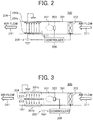
- FIG. 2 is a schematic diagram illustrating a particle collecting device of the first embodiment.
- the particle collecting device 200 illustrated in FIG. 2 includes a duct 201, a blower 202, an ionizing device 203, two electrodes 204, a power supply 205, and a controller 206.
- the controller 206 can be a processor including a central processing unit (CPU) and associated memory units such as a read only memory (ROM), a random access memory (RAM), etc.
- the processor performs various types of control processing by executing programs stored in the memory.
- the duct 201 is a tube formed of an insulating material extending from the inside of the fixing device 9 illustrated in FIG. 1 to the exhaust port 1d provided in the housing 1a of the image forming apparatus 1.
- the blower 202 is a fan that causes the air to flow in the duct 201 in a blowing direction D11 from the inside of the fixing device 9 to the exhaust port 1d.
- the ionizing device 203 is a device disposed inside the duct 201, to ionize the particles contained in the air inside the duct 201.
- the electrodes perform corona discharge. With the corona discharge, the ionizing device 203 ionizes the particles in the air in a neighboring area A11.
- the two electrodes 204 are disposed on a downstream side of the ionizing device 203 in the blowing direction D11 inside the duct 201.
- the two electrodes 204 are face each other and extend along the blowing direction D11.
- One of the two electrodes 204 is a charging electrode 204a and the other is an earth electrode 204b.
- the charging electrode 204a is an electrode to which a voltage is applied by the power supply 205
- the earth electrode 204b is an electrode connected to ground in the housing 1a of the image forming apparatus 1.
- both of the charging electrode 204a and the earth electrode 204b are shaped like flat metal plates, and are disposed adjacent to or on an inner face of the duct 201.
- the power supply 205 is a power supply that charges the charging electrode 204a to cause a potential difference between the two electrodes 204.
- An electric field E11 from the charging electrode 204a toward the earth electrode 204b occurs due to the potential difference caused by the charging.
- the controller 206 is configured to control operations of the blower 202, the ionizing device 203, and the power supply 205.
- the controller 206 is configured to stop the blower 202 when the ionizing device 203 performs the ionization operation.
- the blower 202 causes the air to flow in the blowing direction D11 under the control of the controller 206. With the flow of the air, the air containing the particles generated in the fixing device 9 is taken into the duct 201. At a point of time when the air has been taken in to some extent, the controller 206 stops the blower 202 and causes the ionizing device 203 to perform the ionization operation. Since the blower 202 stops, the ionizing device 203 ionizes the particles in the air retained in the neighboring area A11.
- the controller 206 After having the ionizing device 203 perform the ionization operation for a certain time, the controller 206 causes the blower 202 to resume blowing and causes the power supply 205 to apply the voltage to the charging electrode 204a. Along the electric field E11 that occurs at this time, the particles ionized by the ionizing device 203 move toward the charging electrode 204a and the earth electrode 204b and are collected by the charging electrode 204a and the earth electrode 204b. The air from which the particles are removed is discharged as is through the exhaust port 1d.
- the particle collecting device 200 repeatedly executes the above series of operations at predetermined timing while the image forming apparatus 1 is powered on.
- FIG. 3 is a schematic diagram illustrating a particle collecting device of the second embodiment.
- constituent elements equivalent to the constituent elements in FIG. 2 are denoted by the same reference signs as FIG. 2 , and redundant description of the equivalent constituent elements is hereinafter omitted.
- a particle collecting device 300 illustrated in FIG. 3 includes a blower 202, an ionizing device 203, a power supply 205, and a controller 206 as constituent elements equivalent to the constituent elements of the particle collecting device 200 of the first embodiment illustrated in FIG. 2 .
- the particle collecting device 300 includes a duct 301 and a single electrode 304 as constituent elements different from the constituent elements of the particle collecting device 200 of the first embodiment.
- the duct 301 is a tube extending from an inside of the fixing device 9 illustrated in FIG. 1 to the exhaust port 1d provided in the housing 1a of the image forming apparatus 1.
- the entire wall face including a partial wall face 301a facing the electrode 304 is a metal tube formed of a conductive metal material.
- the wall face of the duct 301, that is, the partial wall face 301a is connected to ground in the housing 1a of the image forming apparatus 1. That is, in the particle collecting device 300 of the second embodiment, the partial wall face 301a facing the electrode 304 serves as an earth electrode in the duct 301.
- the ionizing device 203 is disposed on an upstream side of the partial wall face 301a in a blowing direction D11, that is, on an upstream side of the electrode 304 facing the partial wall face 301a, inside the duct 301.
- the single electrode 304 is disposed inside the duct 301 to extend along the blowing direction D11 and to face the partial wall face 301a.
- the single electrode 304 serves as a charging electrode to which a voltage is applied from the power supply 205.
- a potential difference is caused between the partial wall face 301a and the electrode 304 due to the charging. With the potential difference, an electric field E12 occurs from each of both surfaces of the electrode 304 toward the partial wall face 301a facing the each of the surfaces.
- the electrode 304 is a mesh-like member as follows.
- FIG. 4 is a partially enlarged view illustrating that the electrode illustrated in FIG. 3 is a mesh-like member.
- the electrode 304 is a metal mesh knitted with a plurality of metal wires 304a. As a result, the surface area of the electrode 304 is substantially larger than a case where the electrode 304 is formed of a simple metal plate.
- the blower 202 causes the air to flow in the blowing direction D11, and the air containing particles having occurred in the fixing device 9 is taken into the duct 201 under the control of the controller 206.
- the controller 206 stops the blower 202 and causes the ionizing device 203 to perform an ionization operation.
- the controller 206 causes the blower 202 to resume blowing and causes the power supply 205 to apply a voltage to the electrode 304.
- the electric field E12 that occurs at this time, the ionized particles move toward and are collected by the electrode 304 and the partial wall face 301a of the duct.
- the air after the particles are collected is discharged through the exhaust port 1d.
- the particle collecting device 300 repeatedly executes the above-described series of operations at predetermined timing.
- FIG. 5 is a diagram illustrating a comparative example for comparison with the particle collecting devices of the first and second embodiments.
- a particle collecting device 500 of the comparative example illustrated in FIG. 5 the air is taken into a duct 501 by a blower 502 in a blowing direction D51, and particles contained in the air are ionized by an ionizing electrode 503 and are attracted and collected by a collecting electrode 504.
- the ionizing electrode 503 has a plurality of point-like charging electrodes 503a and flat plate-like earth electrodes 503b alternately arranged, and a voltage is applied from an ionization power supply 505 to each of the point-like charging electrodes 503a.
- the collecting electrode 504 has a plurality of flat plate-like charging electrodes 504a and a plurality of flat plate-like earth electrodes 504b alternately arranged, and a voltage is applied from a collection power supply 506 to each of the plate-like charging electrodes 504a.
- the particle collecting device 500 of this comparative example does not perform the above-described operation control like the particle collecting device 200 or 300 of the first or second embodiment.
- the blower 502 continues to cause the air to flow, and the ionization power supply 505 and the collection power supply 506 continue to apply the voltage on a constant basis during the operation of the particle collecting device 500 of the comparative example.
- the flat plate-like earth electrodes 503b and the point-like charging electrodes 503a are provided in a plurality of pairs, to improve the ionization efficiency in the ionizing electrode 503.
- the flat plate-like earth electrodes 503b are disposed to extend along the blowing direction D51.
- a pressure loss inevitably occurs in the air flowing through the flat plate-like earth electrodes 503b. The same applies to the collecting electrode 504.
- the two particle collection electrodes 204 (or the electrode 304 and the partial partial wall face 301a)facing each other are disposed to extend along the blowing direction D11. Therefore, the pressure loss can be suppressed in the electrodes 204.
- the blower 202 stops when the ionizing device 203 performs the ionization operation. Therefore, the ionization can be performed in the state where the air containing the particles is retained in the neighboring area A11 of the ionizing device 203. With the ionization, the ionization efficiency can be improved and the collection efficiency of the particles at the electrodes 204 or the electrode 304 can be improved. Furthermore, the pressure loss in the ionizing device can be suppressed by simplification of the ionizing device 203 in expectation of improvement of the ionization efficiency and reduction of the number of the particle collection electrodes 204 or 304.
- the single device is disposed near a center of a thickness direction of the duct 201 or 301 and is simplified in the particle collecting device 200 or 300 of the first or second embodiment.
- the single ionizing device 203 may include a single pair of the flat plate-like earth electrode 503b and the point-like charging electrode 503a illustrated in FIG. 5 , for example. With such simplification, an air flow space in the duct 201 or 301 can be widened to suppress the pressure loss around the ionizing device 203.
- the number of the electrodes 204 is reduced to two: the charging electrode 204a and the earth electrode 204b. Since the number of the electrodes 204 is two, the electrodes 204 are disposed near the inner surface of the duct 201 to extend along the blowing direction D11 and the air flow space is widened, whereby the pressure loss can be suppressed. Further, in the particle collecting device 300 of the second embodiment, the number of the electrodes 304 is reduced to one (the charging electrode 204a). Therefore, the air flow space in the duct 301 is widened and the pressure loss can be suppressed.
- the pressure loss can be suppressed in both the ionizing device 203 and the electrodes 204 or the electrode 304, and the collection efficiency of the particles can be improved. That is, both the suppression of the pressure loss and the improvement of the collection efficiency of the particles can be achieved.
- one of the two electrodes 204 is connected to ground. Since the grounded earth electrode 204b does not require charging, the power supply 205 is simplified. As described above, in the particle collecting device 200 of the first embodiment, the number of the electrodes is reduced to two and the charging is performed by the single charging electrode 204a. Therefore, the entire apparatus including the power supply 205 can be simplified and manufacturing cost can be reduced.
- the two electrodes 204 are the plate-like members, which are easily processed. Therefore, parts cost of the electrodes 204 can be reduced.
- the partial wall face 301a facing the electrode 304 is connected to ground in the duct 301, and the power supply 205 charges the electrode 304 alone.
- the charging is performed by the electrode 304 alone, and thus the power supply 205 can be simplified and the manufacturing cost can be reduced.
- the electrode 304 is the mesh-like member and the surface area contributing to the collection of the ionized particles is large. Therefore, the collection efficiency of the particles can be further improved.
- one of the particle collecting devices 200 and 300 according to the first and second embodiments is used to collect the particles contained in the air inside the housing 1a.
- both the suppression of the pressure loss and the improvement of the collection efficiency of the particles can be achieved for exhaust from the housing 1a.
- the electrophotographic image forming apparatus 1 has been exemplified as an example of the image forming apparatus.
- the image forming apparatus is not limited to the example and can be, for example, an inkjet image forming apparatus.
- the particle collecting devices 200, and 300 that collect the particles contained in the air of the fixing device 9 in the electrophotographic image forming apparatus 1 have been exemplified as examples of the particle collecting device.
- the particle collecting device is not limited to the examples and can be a device that collects particles contained in the air at another place in the image forming apparatus.
- the particle collecting device can be a device that collects particles contained in the air of equipment other than the image forming apparatus or can be a device installed alone in a room or the like and which collects particles contained in the ambient air.
- the flat plate-like electrodes 204 have been exemplified as the two electrodes 204 facing each other in the particle collecting device 200 of the first embodiment, as an example of electrodes.
- the mesh-like electrode 304 has been exemplified as the single electrode 304 facing the partial wall face 301a of the duct 301.
- the electrodes are not limited to the example.
- the electrodes facing each other can be mesh-like electrodes, and the electrode facing the partial wall face of the duct can be a flat plate like electrode.
- one of the electrodes facing each other can be a flat plate-like electrode and the other can be a mesh-like electrode.
- the ionizing device 203 that is a single device disposed near the center in the thickness direction of the duct 201 or 301 has been exemplified as an example of the ionizing device.
- the ionizing device is not limited to the example, and the number of installations and installation positions can be arbitrarily set within an allowable range for the pressure loss in the particle collecting device.
- the two electrodes 204 adjacent to the inner surface of the duct 201 have been exemplified as an example of "at least two electrodes".
- the "at least two electrodes” is not limited to the example, and the number of installations and installation positions can be arbitrarily set within an allowable range for the pressure loss in the particle collecting device.
- the power supply 205 that charges the charging electrode 204a alone of the two electrodes 204 has been exemplified as an example of the power supply.
- the power supply 205 that charges the electrode 304 alone, of the partial wall face 301a of the duct 301 and the electrode 304 has been exemplified.
- the power supply is not limited to the example.
- the power supply may charge all of electrodes to have potentials different from one another as long as the power supply charges at least two electrodes to have a potential difference.
- the power supply may charge a partial wall face of a duct and an electrode facing the partial wall face to have potentials different from each other as long as the power supply charges the partial wall face and the electrode to have a potential difference.
- the duct 301 has been exemplified as an example of "a duct having at least a partial wall face formed of a conductive material".
- the entire duct 301 including the partial wall face 301a facing the electrode 304 is formed of the conductive metal.
- the "duct having at least a partial wall face formed of a conductive material” is not limited to the example, and the partial wall face can be formed of a conductive material and the remaining wall face can be formed of an insulating material.
- the particle collecting device 200 in which the two electrodes 204 of the charging electrode 204a and the earth electrode 204b are disposed inside the duct 201 has been exemplified as an example of the particle collecting device.
- the particle collecting device 300 in which the single electrode 304 is disposed inside the duct 301, both surfaces of the electrode 304 facing the partial wall face 301a, has been exemplified.
- the particle collecting device is not limited to the examples, and these two embodiments can be combined, for example.
- two electrodes facing, with one surface, a partial wall face of a duct can be disposed in parallel and away from each other, and one or more pairs of electrodes such as a charging electrode and an earth electrode can be disposed in parallel between the two electrodes.
Landscapes
- Physics & Mathematics (AREA)
- General Physics & Mathematics (AREA)
- Engineering & Computer Science (AREA)
- Life Sciences & Earth Sciences (AREA)
- Chemical & Material Sciences (AREA)
- Health & Medical Sciences (AREA)
- Environmental & Geological Engineering (AREA)
- Environmental Sciences (AREA)
- Ecology (AREA)
- Biodiversity & Conservation Biology (AREA)
- Atmospheric Sciences (AREA)
- Animal Behavior & Ethology (AREA)
- General Health & Medical Sciences (AREA)
- Public Health (AREA)
- Veterinary Medicine (AREA)
- Epidemiology (AREA)
- Analytical Chemistry (AREA)
- General Chemical & Material Sciences (AREA)
- Oil, Petroleum & Natural Gas (AREA)
- Chemical Kinetics & Catalysis (AREA)
- Control Or Security For Electrophotography (AREA)
- Electrophotography Configuration And Component (AREA)
- Electrostatic Separation (AREA)
Abstract
Description
- The present invention relates to a particle collecting device that collects particles in the air, and an image forming apparatus equipped with such a particle collecting device.
- In recent years, in the field of office equipment such as image forming apparatuses, a tendency to suppress a discharge amount of particles such as volatile organic compounds (VOC) and ultrafine particles (UFP) is increasing in order to suppress an influence of on the environment.
- Here, as a particle collecting device that collects particles in the air, a device that ionizes particles and collects the particles with electrodes is known (see, for example,
JP-5774212-B WO2013/161534 )). Such a particle collecting device is mounted in an exhaust path of the air for cooling in office equipment, thereby suppressing the discharge amount of the particles. - Here, the office equipment requires a constant exhaust amount. Therefore, in mounting the particle collecting device in the exhaust path or the like, a pressure loss in the particle collecting device is desirably suppressed as much as possible. Meanwhile, the particle collecting device is required to improve the collection efficiency of the particles. However, structural considerations for improving the collection efficiency increase the pressure loss in some cases. As described above, there is still some room for improvement in the particle collecting devices in terms of suppression of the pressure loss and improvement of the collection efficiency of the particles.
- In view of the above disadvantage, an object of the present invention is to provide a particle collecting device capable of achieving both suppression of a pressure loss and improvement of collection efficiency of particles.
- Advantageously, the particle collecting device includes a duct, a blower, an ionizing device, at least two electrodes, a power supply, and a controller. The blower causes air to flow in a predetermined blowing direction inside the duct. The ionizing device is disposed inside the duct and ionizes particles contained in the air inside the duct. The at least two electrodes is disposed to extend along the blowing direction and faces each other on a downstream side of the ionizing device in the blowing direction inside the duct. The power supply charges at least one of the two electrodes to cause a potential difference between the two electrodes. The controller stops the blower in response to an ionization operation by the ionizing device.
- Advantageously, an image forming apparatus includes a housing; an image forming device disposed inside the housing and configured to form an image on a recording medium; and the particle collecting device described above, disposed inside the housing.
- According to an aspect of the present disclosure, since at least two electrodes facing each other extend along the blowing direction, a pressure loss can be suppressed. According to another aspect of the present disclosure, since the blower is stopped when the ionizing device performs the ionization operation, ionization can be performed in a state where the air including the particles is retained near the ionizing device. With the ionization, the ionization efficiency can be improved and the collection efficiency of the particles at the electrodes can be improved. Accordingly, both the suppression of the pressure loss and the improvement of the collection efficiency of the particles can be achieved.
- The aforementioned and other aspects, features, and advantages of the present disclosure would be better understood by reference to the following detailed description when considered in connection with the accompanying drawings, wherein:
-
FIG. 1 is a diagram illustrating a schematic configuration of an image forming apparatus common to a first embodiment and a second embodiment; -
FIG. 2 is a schematic diagram illustrating a particle collecting device of the first embodiment; -
FIG. 3 is a schematic diagram illustrating a particle collecting device of the second embodiment; -
FIG. 4 is a partially enlarged view illustrating that an electrode illustrated inFIG. 3 is a mesh-like member; and -
FIG. 5 is a diagram illustrating a comparative example for comparison with the particle collecting devices of the first and second embodiments. - The accompanying drawings are intended to depict embodiments of the present disclosure and should not be interpreted to limit the scope thereof. The accompanying drawings are not to be considered as drawn to scale unless explicitly noted.
- In describing embodiments illustrated in the drawings, specific terminology is employed for the sake of clarity. However, the disclosure of this patent specification is not intended to be limited to the specific terminology so selected and it is to be understood that each specific element includes all technical equivalents that operate in a similar manner and achieve similar results.
- Although the embodiments are described with technical limitations with reference to the attached drawings, such description is not intended to limit the scope of the disclosure and all of the components or elements described in the embodiments of this disclosure are not necessarily indispensable.
- Referring now to the drawings, embodiments of the present disclosure are described below. In the drawings for explaining the following embodiments, the same reference codes are allocated to elements (members or components) having the same function or shape and redundant descriptions thereof are omitted below.
- Embodiments of the present disclosure will be described below. As used herein, the singular forms "a", "an", and "the" are intended to include the plural forms as well, unless the context clearly indicates otherwise.
- First, a schematic configuration of an image forming apparatus common to a first embodiment and a second embodiment to be described below will be described.
-
FIG. 1 is a diagram illustrating a schematic configuration of an image forming apparatus common to the first embodiment and the second embodiment. - An image forming apparatus 1 illustrated in
FIG. 1 is used as a copying machine, a printer, a facsimile machine, or a multifunction peripheral of the aforementioned machines, which forms and fixes a toner image on a sheet-like recording medium S. In the present embodiment, a tandem-system full-color image forming apparatus will be described as an example of the image forming apparatus, but a four-cycle full-color image forming apparatus or the like can be used. Alternatively, the image forming apparatus can be a monochrome image forming apparatus or the like. - The image forming apparatus 1 includes a
housing 1a, an image forming device 1b that is disposed inside thehousing 1a, and aparticle collecting device 200. The image forming device 1b forms an image on the recording medium S. Theparticle collecting device 200 is disposed inside thehousing 1a. Theparticle collecting device 200 collects particles contained in the air inside thehousing 1 a and discharges the air to the outside of thehousing 1a. - The image forming device 1b includes an
exposure device 3 that emits laser light, and aprocess unit 5. In theprocess unit 5, an electrostatic latent image is formed with the laser light, and theprocess unit 5 forms a toner image from the electrostatic latent image. The image forming device 1b further includes anintermediate transfer unit 7 to which the toner image is transferred from theprocess unit 5, and asecondary transferer 8 that transfers the toner image from theintermediate transfer unit 7 to the recording medium S. Then, the image forming device 1b includes afixing device 9 that fixes the toner image transferred by thesecondary transferer 8 to the recording medium S. - The image forming device 1b further includes a
stock tray 11 that temporarily holds the recording medium S to which the toner image is fixed, asheet feeding tray 13 that accommodates a plurality of the recording media S, adischarge roller 41, and abottle container 43 that accommodates a toner bottle. Thedischarge roller 41 discharges the recording medium S after fixation to thestock tray 11. - The
exposure device 3 emits laser light according to image information of each of yellow, magenta, cyan, and black (hereinafter, "Y", "M", "C", "K" are attached to members corresponding to the respective colors). Theexposure device 3 includesexposure units exposure units process unit 5, as illustrated inFIG. 1 , and irradiates theprocess unit 5 with the laser light upward from below. - The
process unit 5 includesprocess cartridges process cartridges housing 1a of the image forming apparatus 1 so that theprocess cartridges exposure units process cartridges housing 1a of the image forming apparatus 1. - The
process cartridges yellow process cartridge 100Y will be described as a representative example. Further, in addition, the exposure unit will be described by taking theyellow exposure unit 3Y as an example. - As illustrated in
FIG. 1 , theprocess cartridge 100Y includes aphotoconductor drum 101Y, acharger 102Y, and a developingdevice 103Y. Thephotoconductor drum 101Y is a drum-shaped photoconductor that rotates. Thecharger 102Y charges an outer peripheral surface of thephotoconductor drum 101Y. Then, theexposure unit 3Y is disposed on a downstream side of thecharger 102Y in a rotating direction of thephotoconductor drum 101Y. - In the present embodiment, the
exposure unit 3Y is disposed below thephotoconductor drum 101Y, and emits the laser light upward toward the outer peripheral surface of thephotoconductor drum 101Y from below. The charged outer peripheral surface of thephotoconductor drum 101Y is exposed with the laser light. By the exposure, an electrostatic latent image is formed on the outer peripheral surface of thephotoconductor drum 101Y. - The developing
device 103Y is disposed on a downstream side of theexposure unit 3Y in the rotating direction of thephotoconductor drum 101Y, and develops the electrostatic latent image formed by the exposure. The toner image formed by the development is transferred to theintermediate transfer unit 7 at a transfer position on a downstream side of the developingdevice 103Y in the rotating direction of thephotoconductor drum 101Y, as will be described below. - The
intermediate transfer unit 7 transfers the toner images from theprocess cartridges intermediate transfer unit 7 includes an endlessintermediate transfer belt 27, and a cleaningbackup roller 25 and a secondarytransfer backup roller 12, around which theintermediate transfer belt 27 is stretched, and which allow theintermediate transfer belt 27 to circle. Theintermediate transfer unit 7 further includesprimary transfer rollers intermediate transfer belt 27 between theintermediate transfer unit 7 and the photoconductor drums of theprocess cartridges intermediate transfer unit 7 further includes abelt cleaning device 33. Theintermediate transfer belt 27 circles counterclockwise onFIG. 1 in a state of being held by predetermined tension by atension roller 35. - The
primary transfer rollers process cartridges intermediate transfer belt 27 to primarily transfer the toner image to theintermediate transfer belt 27. - The
secondary transferer 8 includes asecondary transfer roller 31 that presses the recording medium S against theintermediate transfer belt 27. Thesecondary transfer roller 31 is provided to face the secondarytransfer backup roller 12. Thesecondary transfer roller 31 is applied with a bias having a polarity opposite to the polarity of the toner charge, and the toner is attracted from the surface of theintermediate transfer belt 27 toward the recording medium S to secondarily transfer the toner image to the recording medium S. - The
belt cleaning device 33 includes a cleaning blade made of an elastic body such as urethane rubber that abuts on theintermediate transfer belt 27. The cleaning blade comes in contact with theintermediate transfer belt 27 to block and remove a transfer residual toner on the surface of theintermediate transfer belt 27. - The fixing
device 9 receives the recording medium S on which the toner image has been secondarily transferred in a nip formed by two rotators at least one of which carries heat. The fixingdevice 9 heats and pressurizes the recording medium S to fix the toner image on the recording medium S. - The
sheet feeding tray 13 is provided in a lower portion of thehousing 1a of the image forming apparatus 1. A plurality of the recording media S such as paper is accommodated in thesheet feeding tray 13. The recording media S are pulled out from thesheet feeding tray 13 one by one by asheet feeding roller 37 and conveyed along a recording medium conveying path R formed inside thehousing 1a. - The
bottle container 43 is provided in an upper portion of thehousing 1a.Toner bottles bottle container 43. Thetoner bottle 45Y is filled with a yellow toner corresponding to a color separation component of a color image. Thetoner bottle 45M is filled with a magenta toner corresponding to a color separation component of the color image. Thetoner bottle 45C is filled with a cyan toner corresponding to a color separation component of the color image. Thetoner bottle 45K is filled with a black toner corresponding to a color separation component of the color image. - The toners of the respective colors in the
toner bottles process cartridges toner bottles housing 1a independently of theprocess cartridges - Here, in the present embodiment, the
particle collecting device 200 is provided to take in the air heated in the above-describedfixing device 9, at a constant flow rate, and discharges the air through anexhaust port 1d. The fixingdevice 9 is cooled by such an exhaust operation. At this time, particles such as VOC and UFP may be generated in thefixing device 9. Theparticle collecting device 200 takes in the particles together with the air, collects the particles from the air, and discharges the air after from which the particles are removed. - Next, a basic operation of the image forming apparatus 1 configured as described above will be described.
- When an image forming operation is started in the image forming apparatus 1, the respective photoconductor drums of the
process cartridges - Next, the charged surfaces of the photoconductor drums are exposed by the
exposure units - Next, the electrostatic latent images on the surfaces of the photoconductor drums are developed to form toner images of the respective colors. The toner images of the respective colors are sequentially superimposed and transferred by the
primary transfer rollers intermediate transfer belt 27 circling counterclockwise inFIG. 1 . At this time, a full-color toner image is carried on theintermediate transfer belt 27. - Further, the
sheet feeding roller 37 is rotated by a driving device, and one recording medium S is sent out from thesheet feeding tray 13 to the recording medium conveying path R. Timing is controlled by a pair ofregistration rollers 39, and the recording medium S sent out to the recording medium conveying path R is sent to between thesecondary transfer roller 31 and the secondarytransfer backup roller 12 facing thesecondary transfer roller 31. Then, the full-color toner image on theintermediate transfer belt 27 is transferred onto the recording medium S by thesecondary transfer roller 31. Further, the transfer residual toner remaining on the surface of theintermediate transfer belt 27 after the transfer of the toner image is removed by thebelt cleaning device 33. - Next, the recording medium S to which the toner image has been transferred is conveyed to the
fixing device 9. In thefixing device 9, the recording medium S is received in the nip and nipped and conveyed. At that time, heat and pressure are applied to the recording medium S at the nip. With the application of heat and pressure, the toner image is fixed on the recording medium S. Then, the recording medium S having passed through the nip is discharged to thestock tray 11 by thedischarge roller 41. - Further, at this time, the
particle collecting device 200 takes in the air heated generated by the fixing. After collecting the particles such as VOC and UFP, theparticle collecting device 200 discharges the air through theexhaust port 1d. - The image forming apparatus 1 performs such a basic operation to form a full-color image on the recording medium S. In addition to such an operation, a single-color image can be formed using at least one of the
process cartridges process cartridges - Next, descriptions are given below of examples of the above-described
particle collecting device 200 that can be mounted in the image forming apparatus 1. First, the particle collecting device of the first embodiment will be described. -
FIG. 2 is a schematic diagram illustrating a particle collecting device of the first embodiment. - The
particle collecting device 200 illustrated inFIG. 2 includes aduct 201, ablower 202, anionizing device 203, twoelectrodes 204, apower supply 205, and acontroller 206. Thecontroller 206 can be a processor including a central processing unit (CPU) and associated memory units such as a read only memory (ROM), a random access memory (RAM), etc. The processor performs various types of control processing by executing programs stored in the memory. - The
duct 201 is a tube formed of an insulating material extending from the inside of the fixingdevice 9 illustrated inFIG. 1 to theexhaust port 1d provided in thehousing 1a of the image forming apparatus 1. - The
blower 202 is a fan that causes the air to flow in theduct 201 in a blowing direction D11 from the inside of the fixingdevice 9 to theexhaust port 1d. - The
ionizing device 203 is a device disposed inside theduct 201, to ionize the particles contained in the air inside theduct 201. In theionizing device 203, as a built-in high-voltage power supply applies a high voltage to electrodes, the electrodes perform corona discharge. With the corona discharge, theionizing device 203 ionizes the particles in the air in a neighboring area A11. - The two
electrodes 204 are disposed on a downstream side of theionizing device 203 in the blowing direction D11 inside theduct 201. The twoelectrodes 204 are face each other and extend along the blowing direction D11. One of the twoelectrodes 204 is a chargingelectrode 204a and the other is anearth electrode 204b. The chargingelectrode 204a is an electrode to which a voltage is applied by thepower supply 205, and theearth electrode 204b is an electrode connected to ground in thehousing 1a of the image forming apparatus 1. In the present embodiment, both of the chargingelectrode 204a and theearth electrode 204b are shaped like flat metal plates, and are disposed adjacent to or on an inner face of theduct 201. - The
power supply 205 is a power supply that charges the chargingelectrode 204a to cause a potential difference between the twoelectrodes 204. An electric field E11 from the chargingelectrode 204a toward theearth electrode 204b occurs due to the potential difference caused by the charging. - The
controller 206 is configured to control operations of theblower 202, theionizing device 203, and thepower supply 205. Thecontroller 206 is configured to stop theblower 202 when theionizing device 203 performs the ionization operation. - In the
particle collecting device 200 having the above configuration, first, theblower 202 causes the air to flow in the blowing direction D11 under the control of thecontroller 206. With the flow of the air, the air containing the particles generated in thefixing device 9 is taken into theduct 201. At a point of time when the air has been taken in to some extent, thecontroller 206 stops theblower 202 and causes theionizing device 203 to perform the ionization operation. Since theblower 202 stops, theionizing device 203 ionizes the particles in the air retained in the neighboring area A11. After having theionizing device 203 perform the ionization operation for a certain time, thecontroller 206 causes theblower 202 to resume blowing and causes thepower supply 205 to apply the voltage to the chargingelectrode 204a. Along the electric field E11 that occurs at this time, the particles ionized by theionizing device 203 move toward the chargingelectrode 204a and theearth electrode 204b and are collected by the chargingelectrode 204a and theearth electrode 204b. The air from which the particles are removed is discharged as is through theexhaust port 1d. Hereinafter, theparticle collecting device 200 repeatedly executes the above series of operations at predetermined timing while the image forming apparatus 1 is powered on. - Next, the particle collecting device of the second embodiment will be described.
-
FIG. 3 is a schematic diagram illustrating a particle collecting device of the second embodiment. InFIG. 3 , constituent elements equivalent to the constituent elements inFIG. 2 are denoted by the same reference signs asFIG. 2 , and redundant description of the equivalent constituent elements is hereinafter omitted. - First, a
particle collecting device 300 illustrated inFIG. 3 includes ablower 202, anionizing device 203, apower supply 205, and acontroller 206 as constituent elements equivalent to the constituent elements of theparticle collecting device 200 of the first embodiment illustrated inFIG. 2 . Meanwhile, theparticle collecting device 300 includes aduct 301 and asingle electrode 304 as constituent elements different from the constituent elements of theparticle collecting device 200 of the first embodiment. - The
duct 301 is a tube extending from an inside of the fixingdevice 9 illustrated inFIG. 1 to theexhaust port 1d provided in thehousing 1a of the image forming apparatus 1. In the present embodiment, the entire wall face including apartial wall face 301a facing theelectrode 304 is a metal tube formed of a conductive metal material. Then, the wall face of theduct 301, that is, thepartial wall face 301a is connected to ground in thehousing 1a of the image forming apparatus 1. That is, in theparticle collecting device 300 of the second embodiment, thepartial wall face 301a facing theelectrode 304 serves as an earth electrode in theduct 301. - The
ionizing device 203 is disposed on an upstream side of thepartial wall face 301a in a blowing direction D11, that is, on an upstream side of theelectrode 304 facing thepartial wall face 301a, inside theduct 301. - The
single electrode 304 is disposed inside theduct 301 to extend along the blowing direction D11 and to face thepartial wall face 301a. In the present embodiment, thesingle electrode 304 serves as a charging electrode to which a voltage is applied from thepower supply 205. A potential difference is caused between thepartial wall face 301a and theelectrode 304 due to the charging. With the potential difference, an electric field E12 occurs from each of both surfaces of theelectrode 304 toward thepartial wall face 301a facing the each of the surfaces. Here, in the present embodiment, theelectrode 304 is a mesh-like member as follows. -
FIG. 4 is a partially enlarged view illustrating that the electrode illustrated inFIG. 3 is a mesh-like member. - As illustrated in
FIG. 4 , theelectrode 304 is a metal mesh knitted with a plurality ofmetal wires 304a. As a result, the surface area of theelectrode 304 is substantially larger than a case where theelectrode 304 is formed of a simple metal plate. - In the
particle collecting device 300 of the second embodiment illustrated inFIG. 3 , theblower 202 causes the air to flow in the blowing direction D11, and the air containing particles having occurred in thefixing device 9 is taken into theduct 201 under the control of thecontroller 206. Next, thecontroller 206 stops theblower 202 and causes theionizing device 203 to perform an ionization operation. After having theionizing device 203 perform the ionization operation for a certain time, thecontroller 206 causes theblower 202 to resume blowing and causes thepower supply 205 to apply a voltage to theelectrode 304. Along the electric field E12 that occurs at this time, the ionized particles move toward and are collected by theelectrode 304 and thepartial wall face 301a of the duct. The air after the particles are collected is discharged through theexhaust port 1d. Theparticle collecting device 300 repeatedly executes the above-described series of operations at predetermined timing. -
FIG. 5 is a diagram illustrating a comparative example for comparison with the particle collecting devices of the first and second embodiments. - In a
particle collecting device 500 of the comparative example illustrated inFIG. 5 , the air is taken into aduct 501 by ablower 502 in a blowing direction D51, and particles contained in the air are ionized by anionizing electrode 503 and are attracted and collected by a collectingelectrode 504. The ionizingelectrode 503 has a plurality of point-like charging electrodes 503a and flat plate-like earth electrodes 503b alternately arranged, and a voltage is applied from anionization power supply 505 to each of the point-like charging electrodes 503a. Further, the collectingelectrode 504 has a plurality of flat plate-like charging electrodes 504a and a plurality of flat plate-like earth electrodes 504b alternately arranged, and a voltage is applied from acollection power supply 506 to each of the plate-like charging electrodes 504a. - The
particle collecting device 500 of this comparative example does not perform the above-described operation control like theparticle collecting device blower 502 continues to cause the air to flow, and theionization power supply 505 and thecollection power supply 506 continue to apply the voltage on a constant basis during the operation of theparticle collecting device 500 of the comparative example. - Here, in the
particle collecting device 500 of the comparative example, the flat plate-like earth electrodes 503b and the point-like charging electrodes 503a are provided in a plurality of pairs, to improve the ionization efficiency in theionizing electrode 503. The flat plate-like earth electrodes 503b are disposed to extend along the blowing direction D51. However, due to stacking in a louver manner of the plurality of the flat plate-like earth electrodes 503b, a pressure loss inevitably occurs in the air flowing through the flat plate-like earth electrodes 503b. The same applies to the collectingelectrode 504. - According to the
particle collecting device electrode 304 and the partialpartial wall face 301a)facing each other are disposed to extend along the blowing direction D11. Therefore, the pressure loss can be suppressed in theelectrodes 204. Further, theblower 202 stops when theionizing device 203 performs the ionization operation. Therefore, the ionization can be performed in the state where the air containing the particles is retained in the neighboring area A11 of theionizing device 203. With the ionization, the ionization efficiency can be improved and the collection efficiency of the particles at theelectrodes 204 or theelectrode 304 can be improved. Furthermore, the pressure loss in the ionizing device can be suppressed by simplification of theionizing device 203 in expectation of improvement of the ionization efficiency and reduction of the number of theparticle collection electrodes - First, as for the
ionizing device 203, the single device is disposed near a center of a thickness direction of theduct particle collecting device single ionizing device 203 is not specified here, theionizing device 203 may include a single pair of the flat plate-like earth electrode 503b and the point-like charging electrode 503a illustrated inFIG. 5 , for example. With such simplification, an air flow space in theduct ionizing device 203. - In the
particle collecting device 200 of the first embodiment, the number of theelectrodes 204 is reduced to two: the chargingelectrode 204a and theearth electrode 204b. Since the number of theelectrodes 204 is two, theelectrodes 204 are disposed near the inner surface of theduct 201 to extend along the blowing direction D11 and the air flow space is widened, whereby the pressure loss can be suppressed. Further, in theparticle collecting device 300 of the second embodiment, the number of theelectrodes 304 is reduced to one (the chargingelectrode 204a). Therefore, the air flow space in theduct 301 is widened and the pressure loss can be suppressed. - As described above, according to the
particle collecting device ionizing device 203 and theelectrodes 204 or theelectrode 304, and the collection efficiency of the particles can be improved. That is, both the suppression of the pressure loss and the improvement of the collection efficiency of the particles can be achieved. - Further, in the
particle collecting device 200 of the first embodiment, one of the twoelectrodes 204 is connected to ground. Since the groundedearth electrode 204b does not require charging, thepower supply 205 is simplified. As described above, in theparticle collecting device 200 of the first embodiment, the number of the electrodes is reduced to two and the charging is performed by thesingle charging electrode 204a. Therefore, the entire apparatus including thepower supply 205 can be simplified and manufacturing cost can be reduced. - Further, according to the
particle collecting device 200 of the first embodiment, the twoelectrodes 204 are the plate-like members, which are easily processed. Therefore, parts cost of theelectrodes 204 can be reduced. - Further, in the
particle collecting device 300 of the second embodiment, thepartial wall face 301a facing theelectrode 304 is connected to ground in theduct 301, and thepower supply 205 charges theelectrode 304 alone. With the configuration, the charging is performed by theelectrode 304 alone, and thus thepower supply 205 can be simplified and the manufacturing cost can be reduced. - Further, according to the
particle collecting device 300 of the second embodiment, theelectrode 304 is the mesh-like member and the surface area contributing to the collection of the ionized particles is large. Therefore, the collection efficiency of the particles can be further improved. - In the image forming apparatus 1 illustrated in
FIG. 1 , one of theparticle collecting devices housing 1a. With the configuration, both the suppression of the pressure loss and the improvement of the collection efficiency of the particles can be achieved for exhaust from thehousing 1a. - Note that the above-described embodiments are merely representative forms of the present invention, and the present invention is not limited to these embodiments. That is, a person skilled in the art can make and implement various modifications within a range not deviating from the gist of the present invention according to conventionally known knowledge. Even such modifications are of course included in the scope of the present invention as long as the modifications have any of the configurations of the particle collecting device and the image forming apparatus of the present invention.
- For example, in the above-described first and second embodiments, the electrophotographic image forming apparatus 1 has been exemplified as an example of the image forming apparatus. However, the image forming apparatus is not limited to the example and can be, for example, an inkjet image forming apparatus.
- In the above-described first and second embodiments, the
particle collecting devices device 9 in the electrophotographic image forming apparatus 1 have been exemplified as examples of the particle collecting device. However, the particle collecting device is not limited to the examples and can be a device that collects particles contained in the air at another place in the image forming apparatus. Alternatively, the particle collecting device can be a device that collects particles contained in the air of equipment other than the image forming apparatus or can be a device installed alone in a room or the like and which collects particles contained in the ambient air. - Further, in the above-described first embodiment, the flat plate-
like electrodes 204 have been exemplified as the twoelectrodes 204 facing each other in theparticle collecting device 200 of the first embodiment, as an example of electrodes. Further, in theparticle collecting device 300 of the second embodiment, the mesh-like electrode 304 has been exemplified as thesingle electrode 304 facing thepartial wall face 301a of theduct 301. However, the electrodes are not limited to the example. For example, the electrodes facing each other can be mesh-like electrodes, and the electrode facing the partial wall face of the duct can be a flat plate like electrode. Alternatively, one of the electrodes facing each other can be a flat plate-like electrode and the other can be a mesh-like electrode. - Further, in the above-described first or second embodiment, the
ionizing device 203 that is a single device disposed near the center in the thickness direction of theduct - Further, in the above-described first embodiment, the two
electrodes 204 adjacent to the inner surface of theduct 201 have been exemplified as an example of "at least two electrodes". However, the "at least two electrodes" is not limited to the example, and the number of installations and installation positions can be arbitrarily set within an allowable range for the pressure loss in the particle collecting device. - Further, in the above-described first embodiment, the
power supply 205 that charges the chargingelectrode 204a alone of the twoelectrodes 204 has been exemplified as an example of the power supply. Further, in the second embodiment, thepower supply 205 that charges theelectrode 304 alone, of thepartial wall face 301a of theduct 301 and theelectrode 304, has been exemplified. However, the power supply is not limited to the example. The power supply may charge all of electrodes to have potentials different from one another as long as the power supply charges at least two electrodes to have a potential difference. Further, the power supply may charge a partial wall face of a duct and an electrode facing the partial wall face to have potentials different from each other as long as the power supply charges the partial wall face and the electrode to have a potential difference. - Further, in the above-described first embodiment, the
duct 301 has been exemplified as an example of "a duct having at least a partial wall face formed of a conductive material". Theentire duct 301 including thepartial wall face 301a facing theelectrode 304 is formed of the conductive metal. However, the "duct having at least a partial wall face formed of a conductive material" is not limited to the example, and the partial wall face can be formed of a conductive material and the remaining wall face can be formed of an insulating material. - Further, in the above-described first embodiment, the
particle collecting device 200 in which the twoelectrodes 204 of the chargingelectrode 204a and theearth electrode 204b are disposed inside theduct 201 has been exemplified as an example of the particle collecting device. Further, in the second embodiment, theparticle collecting device 300 in which thesingle electrode 304 is disposed inside theduct 301, both surfaces of theelectrode 304 facing thepartial wall face 301a, has been exemplified. However, the particle collecting device is not limited to the examples, and these two embodiments can be combined, for example. That is, two electrodes facing, with one surface, a partial wall face of a duct can be disposed in parallel and away from each other, and one or more pairs of electrodes such as a charging electrode and an earth electrode can be disposed in parallel between the two electrodes.
Claims (8)
- A particle collecting device (200) comprising:a duct (201);a blower (202) configured to cause air to flow in a predetermined blowing direction (D11) inside the duct (201);an ionizing device (203) disposed inside the duct (201) and configured to ionize particles contained in the air inside the duct (201);at least two electrodes (204; 301a,304) extending along the predetermined blowing direction (D11) and facing each other, the at least two electrodes (204; 301a,304) disposed downstream from the ionizing device (203) inside the duct (201) in the predetermined blowing direction (D11);a power supply (205) configured to charge at least one of the at least two electrodes (204; 301a,304) to cause a potential difference between the at least two electrodes (204; 301a,304); anda controller (206) configured to:control the blower (202), the ionizing device (203), and the power supply (205); andstop the blower (202) in response to an ionization operation by the ionizing device (203).
- The particle collecting device (200) according to claim 1,
wherein at least one of the at least two electrodes (204; 301a,304) is grounded. - The particle collecting device (200) according to claim 2,
wherein the at least two electrodes (204; 301a,304) are two electrodes (204; 301a,304), and
wherein one of the two electrodes (204; 301a,304) is grounded. - The particle collecting device (300) according to claim 1 or 2,
wherein the at least two electrodes (301a,304) are two electrodes (301a,304), and
wherein one of the two electrodes (301a,304) is a wall face (301a) of the duct (301) facing the other (304) of the two electrodes (301a,304), the wall face (301a) formed of a conductive material. - The particle collecting device (300) according to claim 4,
wherein the wall face (301a) of the duct (301) is grounded, and
the power supply (205) is configured to charge only the other (304) of the two electrode (301a,304). - The particle collecting device (200 or 300) according to any one of claims 1 to 5,
wherein the at least two electrodes (204; 301a,304) includes an electrode (204a; 204b) shaped into a flat plate. - The particle collecting device (200 or 300) according to any one of claims 1 to 5,
wherein the at least two electrodes (204; 301a,304) includes an electrode (304) shaped into a mesh. - An image forming apparatus (1) comprising:a housing (1a);an image forming device (1b) disposed inside the housing (1a) and configured to form an image on a recording medium (S); andthe particle collecting device (200 or 300) according to any one of claims 1 to 7, disposed inside the housing (1a),wherein the particle collecting device (200 or 300) is configured to collect particles contained in air inside the housing (1a) and discharge the air to an outside of the housing (1a).
Applications Claiming Priority (1)
| Application Number | Priority Date | Filing Date | Title |
|---|---|---|---|
| JP2018043759A JP7163594B2 (en) | 2018-03-12 | 2018-03-12 | Fine particle collection device and image forming device |
Publications (2)
| Publication Number | Publication Date |
|---|---|
| EP3540881A1 true EP3540881A1 (en) | 2019-09-18 |
| EP3540881B1 EP3540881B1 (en) | 2020-06-17 |
Family
ID=65724184
Family Applications (1)
| Application Number | Title | Priority Date | Filing Date |
|---|---|---|---|
| EP19161102.9A Not-in-force EP3540881B1 (en) | 2018-03-12 | 2019-03-06 | Particle collecting device and image forming apparatus |
Country Status (3)
| Country | Link |
|---|---|
| US (1) | US20190278222A1 (en) |
| EP (1) | EP3540881B1 (en) |
| JP (1) | JP7163594B2 (en) |
Families Citing this family (7)
| Publication number | Priority date | Publication date | Assignee | Title |
|---|---|---|---|---|
| JP2020153718A (en) | 2019-03-18 | 2020-09-24 | 株式会社リコー | Measuring equipment and modeling equipment |
| JP2021009226A (en) * | 2019-07-01 | 2021-01-28 | ヒューレット−パッカード デベロップメント カンパニー エル.ピー.Hewlett‐Packard Development Company, L.P. | Image forming system including ionizer that is selectively controlled |
| KR20210009518A (en) * | 2019-07-17 | 2021-01-27 | 휴렛-팩커드 디벨롭먼트 컴퍼니, 엘.피. | Cooling and air purifying structure of image forming apparatus |
| JP7327056B2 (en) | 2019-09-30 | 2023-08-16 | 株式会社リコー | image forming device |
| JP7327054B2 (en) | 2019-09-30 | 2023-08-16 | 株式会社リコー | image forming device |
| JP2021144182A (en) * | 2020-03-13 | 2021-09-24 | ヒューレット−パッカード デベロップメント カンパニー エル.ピー.Hewlett‐Packard Development Company, L.P. | Image forming system having collection device for fixing device, and control unit for image forming system |
| JP7516979B2 (en) * | 2020-08-24 | 2024-07-17 | セイコーエプソン株式会社 | Liquid ejection device and drying device |
Citations (3)
| Publication number | Priority date | Publication date | Assignee | Title |
|---|---|---|---|---|
| US20100201776A1 (en) * | 2009-02-10 | 2010-08-12 | Kazumasa Tonami | Image forming apparatus |
| WO2013161534A1 (en) | 2012-04-23 | 2013-10-31 | 三菱電機株式会社 | Corona discharge device and air conditioner |
| EP3276430A1 (en) * | 2016-07-25 | 2018-01-31 | Ricoh Company, Ltd. | Image forming apparatus |
Family Cites Families (13)
| Publication number | Priority date | Publication date | Assignee | Title |
|---|---|---|---|---|
| JPS6325156U (en) * | 1986-07-29 | 1988-02-19 | ||
| JPH0721233Y2 (en) * | 1988-10-31 | 1995-05-17 | シャープ株式会社 | Air cleaner |
| JPH09108591A (en) * | 1995-10-18 | 1997-04-28 | Zexel Corp | Air purifier |
| JP3030984U (en) * | 1996-05-08 | 1996-11-12 | 森田電工株式会社 | Electrostatic air purifier |
| JPH10216559A (en) * | 1997-01-31 | 1998-08-18 | Midori Anzen Co Ltd | Air purifier |
| JP3488367B2 (en) * | 1997-08-06 | 2004-01-19 | 株式会社コロナ | Air cleaner |
| US7638104B2 (en) * | 2004-03-02 | 2009-12-29 | Sharper Image Acquisition Llc | Air conditioner device including pin-ring electrode configurations with driver electrode |
| US8043412B2 (en) * | 2005-06-16 | 2011-10-25 | Savannah River Nuclear Solutions, Llc | High volume, multiple use, portable precipitator |
| JP6335585B2 (en) * | 2013-04-19 | 2018-05-30 | キヤノン株式会社 | Image forming apparatus |
| JP6188650B2 (en) * | 2014-07-24 | 2017-08-30 | 京セラドキュメントソリューションズ株式会社 | Image forming apparatus |
| BR112018006125B1 (en) * | 2015-09-28 | 2022-11-08 | Massachusetts Institute Of Technology | SYSTEMS AND METHODS FOR COLLECTING A FLUID SPECIES |
| JP2018022130A (en) * | 2016-07-25 | 2018-02-08 | 株式会社リコー | Image forming apparatus |
| JP7251064B2 (en) * | 2018-07-19 | 2023-04-04 | 富士フイルムビジネスイノベーション株式会社 | Channel structure and image forming apparatus |
-
2018
- 2018-03-12 JP JP2018043759A patent/JP7163594B2/en active Active
-
2019
- 2019-03-06 EP EP19161102.9A patent/EP3540881B1/en not_active Not-in-force
- 2019-03-11 US US16/297,831 patent/US20190278222A1/en not_active Abandoned
Patent Citations (5)
| Publication number | Priority date | Publication date | Assignee | Title |
|---|---|---|---|---|
| US20100201776A1 (en) * | 2009-02-10 | 2010-08-12 | Kazumasa Tonami | Image forming apparatus |
| WO2013161534A1 (en) | 2012-04-23 | 2013-10-31 | 三菱電機株式会社 | Corona discharge device and air conditioner |
| JP5774212B2 (en) | 2012-04-23 | 2015-09-09 | 三菱電機株式会社 | Corona discharge device and air conditioner |
| US20150290352A1 (en) * | 2012-04-23 | 2015-10-15 | Mitsubishi Electric Corporation | Corona discharge device and air-conditioning apparatus |
| EP3276430A1 (en) * | 2016-07-25 | 2018-01-31 | Ricoh Company, Ltd. | Image forming apparatus |
Also Published As
| Publication number | Publication date |
|---|---|
| JP7163594B2 (en) | 2022-11-01 |
| US20190278222A1 (en) | 2019-09-12 |
| JP2019155246A (en) | 2019-09-19 |
| EP3540881B1 (en) | 2020-06-17 |
Similar Documents
| Publication | Publication Date | Title |
|---|---|---|
| EP3540881B1 (en) | Particle collecting device and image forming apparatus | |
| JP6394936B2 (en) | Image forming apparatus and driving method of image forming apparatus | |
| US12078958B2 (en) | Image forming apparatus | |
| US10248043B2 (en) | Image forming apparatus that prevents toner charged with polarity opposite normal charging polarity from being collected | |
| EP3382457B1 (en) | Fixing device and image forming apparatus | |
| US7945190B2 (en) | Cleanerless image forming apparatus | |
| US12092993B2 (en) | Image forming apparatus | |
| US11977350B2 (en) | Image forming apparatus | |
| US10496010B2 (en) | Developing device and image forming apparatus | |
| EP2325702A1 (en) | Image forming apparatus | |
| JP4307899B2 (en) | Image forming apparatus | |
| JP4622515B2 (en) | Image forming apparatus | |
| JP2012013718A (en) | Image forming device | |
| US11467534B2 (en) | Cooling and air purifying structure of image forming apparatus | |
| JP6123359B2 (en) | Image forming apparatus | |
| JP4059012B2 (en) | Image forming apparatus | |
| US7848691B2 (en) | Transfer unit and image forming apparatus employing the same | |
| JP2008287069A (en) | Charging device and image forming apparatus | |
| JP6065223B2 (en) | Charging method and image forming method | |
| JP4288289B2 (en) | Ion generator and image forming apparatus having the same | |
| JP2010230821A (en) | Toner suction device and image forming apparatus | |
| EP2634640A2 (en) | Discharge device | |
| JP2004287316A (en) | Image forming apparatus | |
| JP6631551B2 (en) | Fixing device and image forming device | |
| JP2007219090A (en) | Image forming apparatus |
Legal Events
| Date | Code | Title | Description |
|---|---|---|---|
| PUAI | Public reference made under article 153(3) epc to a published international application that has entered the european phase |
Free format text: ORIGINAL CODE: 0009012 |
|
| STAA | Information on the status of an ep patent application or granted ep patent |
Free format text: STATUS: REQUEST FOR EXAMINATION WAS MADE |
|
| 17P | Request for examination filed |
Effective date: 20190306 |
|
| AK | Designated contracting states |
Kind code of ref document: A1 Designated state(s): AL AT BE BG CH CY CZ DE DK EE ES FI FR GB GR HR HU IE IS IT LI LT LU LV MC MK MT NL NO PL PT RO RS SE SI SK SM TR |
|
| AX | Request for extension of the european patent |
Extension state: BA ME |
|
| GRAP | Despatch of communication of intention to grant a patent |
Free format text: ORIGINAL CODE: EPIDOSNIGR1 |
|
| STAA | Information on the status of an ep patent application or granted ep patent |
Free format text: STATUS: GRANT OF PATENT IS INTENDED |
|
| RIC1 | Information provided on ipc code assigned before grant |
Ipc: A61L 9/22 20060101ALI20200302BHEP Ipc: B03C 3/12 20060101ALI20200302BHEP Ipc: H01T 23/00 20060101AFI20200302BHEP Ipc: B03C 3/08 20060101ALI20200302BHEP |
|
| INTG | Intention to grant announced |
Effective date: 20200319 |
|
| GRAS | Grant fee paid |
Free format text: ORIGINAL CODE: EPIDOSNIGR3 |
|
| GRAA | (expected) grant |
Free format text: ORIGINAL CODE: 0009210 |
|
| STAA | Information on the status of an ep patent application or granted ep patent |
Free format text: STATUS: THE PATENT HAS BEEN GRANTED |
|
| AK | Designated contracting states |
Kind code of ref document: B1 Designated state(s): AL AT BE BG CH CY CZ DE DK EE ES FI FR GB GR HR HU IE IS IT LI LT LU LV MC MK MT NL NO PL PT RO RS SE SI SK SM TR |
|
| REG | Reference to a national code |
Ref country code: GB Ref legal event code: FG4D |
|
| REG | Reference to a national code |
Ref country code: CH Ref legal event code: EP |
|
| REG | Reference to a national code |
Ref country code: IE Ref legal event code: FG4D |
|
| REG | Reference to a national code |
Ref country code: DE Ref legal event code: R096 Ref document number: 602019000182 Country of ref document: DE |
|
| REG | Reference to a national code |
Ref country code: AT Ref legal event code: REF Ref document number: 1282497 Country of ref document: AT Kind code of ref document: T Effective date: 20200715 |
|
| REG | Reference to a national code |
Ref country code: NL Ref legal event code: FP |
|
| PG25 | Lapsed in a contracting state [announced via postgrant information from national office to epo] |
Ref country code: SE Free format text: LAPSE BECAUSE OF FAILURE TO SUBMIT A TRANSLATION OF THE DESCRIPTION OR TO PAY THE FEE WITHIN THE PRESCRIBED TIME-LIMIT Effective date: 20200617 Ref country code: NO Free format text: LAPSE BECAUSE OF FAILURE TO SUBMIT A TRANSLATION OF THE DESCRIPTION OR TO PAY THE FEE WITHIN THE PRESCRIBED TIME-LIMIT Effective date: 20200917 Ref country code: FI Free format text: LAPSE BECAUSE OF FAILURE TO SUBMIT A TRANSLATION OF THE DESCRIPTION OR TO PAY THE FEE WITHIN THE PRESCRIBED TIME-LIMIT Effective date: 20200617 Ref country code: GR Free format text: LAPSE BECAUSE OF FAILURE TO SUBMIT A TRANSLATION OF THE DESCRIPTION OR TO PAY THE FEE WITHIN THE PRESCRIBED TIME-LIMIT Effective date: 20200918 Ref country code: LT Free format text: LAPSE BECAUSE OF FAILURE TO SUBMIT A TRANSLATION OF THE DESCRIPTION OR TO PAY THE FEE WITHIN THE PRESCRIBED TIME-LIMIT Effective date: 20200617 |
|
| REG | Reference to a national code |
Ref country code: LT Ref legal event code: MG4D |
|
| PG25 | Lapsed in a contracting state [announced via postgrant information from national office to epo] |
Ref country code: LV Free format text: LAPSE BECAUSE OF FAILURE TO SUBMIT A TRANSLATION OF THE DESCRIPTION OR TO PAY THE FEE WITHIN THE PRESCRIBED TIME-LIMIT Effective date: 20200617 Ref country code: HR Free format text: LAPSE BECAUSE OF FAILURE TO SUBMIT A TRANSLATION OF THE DESCRIPTION OR TO PAY THE FEE WITHIN THE PRESCRIBED TIME-LIMIT Effective date: 20200617 Ref country code: RS Free format text: LAPSE BECAUSE OF FAILURE TO SUBMIT A TRANSLATION OF THE DESCRIPTION OR TO PAY THE FEE WITHIN THE PRESCRIBED TIME-LIMIT Effective date: 20200617 Ref country code: BG Free format text: LAPSE BECAUSE OF FAILURE TO SUBMIT A TRANSLATION OF THE DESCRIPTION OR TO PAY THE FEE WITHIN THE PRESCRIBED TIME-LIMIT Effective date: 20200917 |
|
| REG | Reference to a national code |
Ref country code: AT Ref legal event code: MK05 Ref document number: 1282497 Country of ref document: AT Kind code of ref document: T Effective date: 20200617 |
|
| PG25 | Lapsed in a contracting state [announced via postgrant information from national office to epo] |
Ref country code: AL Free format text: LAPSE BECAUSE OF FAILURE TO SUBMIT A TRANSLATION OF THE DESCRIPTION OR TO PAY THE FEE WITHIN THE PRESCRIBED TIME-LIMIT Effective date: 20200617 |
|
| PG25 | Lapsed in a contracting state [announced via postgrant information from national office to epo] |
Ref country code: RO Free format text: LAPSE BECAUSE OF FAILURE TO SUBMIT A TRANSLATION OF THE DESCRIPTION OR TO PAY THE FEE WITHIN THE PRESCRIBED TIME-LIMIT Effective date: 20200617 Ref country code: IT Free format text: LAPSE BECAUSE OF FAILURE TO SUBMIT A TRANSLATION OF THE DESCRIPTION OR TO PAY THE FEE WITHIN THE PRESCRIBED TIME-LIMIT Effective date: 20200617 Ref country code: SM Free format text: LAPSE BECAUSE OF FAILURE TO SUBMIT A TRANSLATION OF THE DESCRIPTION OR TO PAY THE FEE WITHIN THE PRESCRIBED TIME-LIMIT Effective date: 20200617 Ref country code: EE Free format text: LAPSE BECAUSE OF FAILURE TO SUBMIT A TRANSLATION OF THE DESCRIPTION OR TO PAY THE FEE WITHIN THE PRESCRIBED TIME-LIMIT Effective date: 20200617 Ref country code: AT Free format text: LAPSE BECAUSE OF FAILURE TO SUBMIT A TRANSLATION OF THE DESCRIPTION OR TO PAY THE FEE WITHIN THE PRESCRIBED TIME-LIMIT Effective date: 20200617 Ref country code: PT Free format text: LAPSE BECAUSE OF FAILURE TO SUBMIT A TRANSLATION OF THE DESCRIPTION OR TO PAY THE FEE WITHIN THE PRESCRIBED TIME-LIMIT Effective date: 20201019 Ref country code: ES Free format text: LAPSE BECAUSE OF FAILURE TO SUBMIT A TRANSLATION OF THE DESCRIPTION OR TO PAY THE FEE WITHIN THE PRESCRIBED TIME-LIMIT Effective date: 20200617 Ref country code: CZ Free format text: LAPSE BECAUSE OF FAILURE TO SUBMIT A TRANSLATION OF THE DESCRIPTION OR TO PAY THE FEE WITHIN THE PRESCRIBED TIME-LIMIT Effective date: 20200617 |
|
| PG25 | Lapsed in a contracting state [announced via postgrant information from national office to epo] |
Ref country code: SK Free format text: LAPSE BECAUSE OF FAILURE TO SUBMIT A TRANSLATION OF THE DESCRIPTION OR TO PAY THE FEE WITHIN THE PRESCRIBED TIME-LIMIT Effective date: 20200617 Ref country code: PL Free format text: LAPSE BECAUSE OF FAILURE TO SUBMIT A TRANSLATION OF THE DESCRIPTION OR TO PAY THE FEE WITHIN THE PRESCRIBED TIME-LIMIT Effective date: 20200617 Ref country code: IS Free format text: LAPSE BECAUSE OF FAILURE TO SUBMIT A TRANSLATION OF THE DESCRIPTION OR TO PAY THE FEE WITHIN THE PRESCRIBED TIME-LIMIT Effective date: 20201017 |
|
| REG | Reference to a national code |
Ref country code: DE Ref legal event code: R097 Ref document number: 602019000182 Country of ref document: DE |
|
| PLBE | No opposition filed within time limit |
Free format text: ORIGINAL CODE: 0009261 |
|
| STAA | Information on the status of an ep patent application or granted ep patent |
Free format text: STATUS: NO OPPOSITION FILED WITHIN TIME LIMIT |
|
| PG25 | Lapsed in a contracting state [announced via postgrant information from national office to epo] |
Ref country code: DK Free format text: LAPSE BECAUSE OF FAILURE TO SUBMIT A TRANSLATION OF THE DESCRIPTION OR TO PAY THE FEE WITHIN THE PRESCRIBED TIME-LIMIT Effective date: 20200617 |
|
| 26N | No opposition filed |
Effective date: 20210318 |
|
| PG25 | Lapsed in a contracting state [announced via postgrant information from national office to epo] |
Ref country code: MC Free format text: LAPSE BECAUSE OF FAILURE TO SUBMIT A TRANSLATION OF THE DESCRIPTION OR TO PAY THE FEE WITHIN THE PRESCRIBED TIME-LIMIT Effective date: 20200617 |
|
| REG | Reference to a national code |
Ref country code: BE Ref legal event code: MM Effective date: 20210331 |
|
| PG25 | Lapsed in a contracting state [announced via postgrant information from national office to epo] |
Ref country code: IE Free format text: LAPSE BECAUSE OF NON-PAYMENT OF DUE FEES Effective date: 20210306 Ref country code: LU Free format text: LAPSE BECAUSE OF NON-PAYMENT OF DUE FEES Effective date: 20210306 |
|
| PGFP | Annual fee paid to national office [announced via postgrant information from national office to epo] |
Ref country code: DE Payment date: 20220322 Year of fee payment: 4 |
|
| PGFP | Annual fee paid to national office [announced via postgrant information from national office to epo] |
Ref country code: NL Payment date: 20220321 Year of fee payment: 4 Ref country code: FR Payment date: 20220322 Year of fee payment: 4 |
|
| PG25 | Lapsed in a contracting state [announced via postgrant information from national office to epo] |
Ref country code: BE Free format text: LAPSE BECAUSE OF NON-PAYMENT OF DUE FEES Effective date: 20210331 |
|
| REG | Reference to a national code |
Ref country code: CH Ref legal event code: PL |
|
| PG25 | Lapsed in a contracting state [announced via postgrant information from national office to epo] |
Ref country code: LI Free format text: LAPSE BECAUSE OF NON-PAYMENT OF DUE FEES Effective date: 20220331 Ref country code: CH Free format text: LAPSE BECAUSE OF NON-PAYMENT OF DUE FEES Effective date: 20220331 |
|
| PG25 | Lapsed in a contracting state [announced via postgrant information from national office to epo] |
Ref country code: CY Free format text: LAPSE BECAUSE OF FAILURE TO SUBMIT A TRANSLATION OF THE DESCRIPTION OR TO PAY THE FEE WITHIN THE PRESCRIBED TIME-LIMIT Effective date: 20200617 |
|
| PG25 | Lapsed in a contracting state [announced via postgrant information from national office to epo] |
Ref country code: HU Free format text: LAPSE BECAUSE OF FAILURE TO SUBMIT A TRANSLATION OF THE DESCRIPTION OR TO PAY THE FEE WITHIN THE PRESCRIBED TIME-LIMIT; INVALID AB INITIO Effective date: 20190306 |
|
| PG25 | Lapsed in a contracting state [announced via postgrant information from national office to epo] |
Ref country code: SI Free format text: LAPSE BECAUSE OF FAILURE TO SUBMIT A TRANSLATION OF THE DESCRIPTION OR TO PAY THE FEE WITHIN THE PRESCRIBED TIME-LIMIT Effective date: 20200617 |
|
| REG | Reference to a national code |
Ref country code: DE Ref legal event code: R119 Ref document number: 602019000182 Country of ref document: DE |
|
| REG | Reference to a national code |
Ref country code: NL Ref legal event code: MM Effective date: 20230401 |
|
| GBPC | Gb: european patent ceased through non-payment of renewal fee |
Effective date: 20230306 |
|
| PG25 | Lapsed in a contracting state [announced via postgrant information from national office to epo] |
Ref country code: NL Free format text: LAPSE BECAUSE OF NON-PAYMENT OF DUE FEES Effective date: 20230401 |
|
| PG25 | Lapsed in a contracting state [announced via postgrant information from national office to epo] |
Ref country code: GB Free format text: LAPSE BECAUSE OF NON-PAYMENT OF DUE FEES Effective date: 20230306 |
|
| PG25 | Lapsed in a contracting state [announced via postgrant information from national office to epo] |
Ref country code: GB Free format text: LAPSE BECAUSE OF NON-PAYMENT OF DUE FEES Effective date: 20230306 Ref country code: FR Free format text: LAPSE BECAUSE OF NON-PAYMENT OF DUE FEES Effective date: 20230331 Ref country code: DE Free format text: LAPSE BECAUSE OF NON-PAYMENT OF DUE FEES Effective date: 20231003 |
|
| PG25 | Lapsed in a contracting state [announced via postgrant information from national office to epo] |
Ref country code: MK Free format text: LAPSE BECAUSE OF FAILURE TO SUBMIT A TRANSLATION OF THE DESCRIPTION OR TO PAY THE FEE WITHIN THE PRESCRIBED TIME-LIMIT Effective date: 20200617 |
|
| PG25 | Lapsed in a contracting state [announced via postgrant information from national office to epo] |
Ref country code: TR Free format text: LAPSE BECAUSE OF FAILURE TO SUBMIT A TRANSLATION OF THE DESCRIPTION OR TO PAY THE FEE WITHIN THE PRESCRIBED TIME-LIMIT Effective date: 20200617 |
|
| PG25 | Lapsed in a contracting state [announced via postgrant information from national office to epo] |
Ref country code: MT Free format text: LAPSE BECAUSE OF FAILURE TO SUBMIT A TRANSLATION OF THE DESCRIPTION OR TO PAY THE FEE WITHIN THE PRESCRIBED TIME-LIMIT Effective date: 20200617 |