EP3540867B1 - Connector housing and adapter - Google Patents
Connector housing and adapter Download PDFInfo
- Publication number
- EP3540867B1 EP3540867B1 EP18305292.7A EP18305292A EP3540867B1 EP 3540867 B1 EP3540867 B1 EP 3540867B1 EP 18305292 A EP18305292 A EP 18305292A EP 3540867 B1 EP3540867 B1 EP 3540867B1
- Authority
- EP
- European Patent Office
- Prior art keywords
- module
- adapter
- connector
- connector housing
- locking
- Prior art date
- Legal status (The legal status is an assumption and is not a legal conclusion. Google has not performed a legal analysis and makes no representation as to the accuracy of the status listed.)
- Active
Links
Images




Classifications
-
- H—ELECTRICITY
- H01—ELECTRIC ELEMENTS
- H01R—ELECTRICALLY-CONDUCTIVE CONNECTIONS; STRUCTURAL ASSOCIATIONS OF A PLURALITY OF MUTUALLY-INSULATED ELECTRICAL CONNECTING ELEMENTS; COUPLING DEVICES; CURRENT COLLECTORS
- H01R13/00—Details of coupling devices of the kinds covered by groups H01R12/70 or H01R24/00 - H01R33/00
- H01R13/62—Means for facilitating engagement or disengagement of coupling parts or for holding them in engagement
- H01R13/629—Additional means for facilitating engagement or disengagement of coupling parts, e.g. aligning or guiding means, levers, gas pressure electrical locking indicators, manufacturing tolerances
- H01R13/62905—Additional means for facilitating engagement or disengagement of coupling parts, e.g. aligning or guiding means, levers, gas pressure electrical locking indicators, manufacturing tolerances comprising a camming member
- H01R13/62927—Comprising supplementary or additional locking means
-
- H—ELECTRICITY
- H01—ELECTRIC ELEMENTS
- H01R—ELECTRICALLY-CONDUCTIVE CONNECTIONS; STRUCTURAL ASSOCIATIONS OF A PLURALITY OF MUTUALLY-INSULATED ELECTRICAL CONNECTING ELEMENTS; COUPLING DEVICES; CURRENT COLLECTORS
- H01R13/00—Details of coupling devices of the kinds covered by groups H01R12/70 or H01R24/00 - H01R33/00
- H01R13/46—Bases; Cases
- H01R13/502—Bases; Cases composed of different pieces
- H01R13/504—Bases; Cases composed of different pieces different pieces being moulded, cemented, welded, e.g. ultrasonic welding, or swaged together
-
- H—ELECTRICITY
- H01—ELECTRIC ELEMENTS
- H01R—ELECTRICALLY-CONDUCTIVE CONNECTIONS; STRUCTURAL ASSOCIATIONS OF A PLURALITY OF MUTUALLY-INSULATED ELECTRICAL CONNECTING ELEMENTS; COUPLING DEVICES; CURRENT COLLECTORS
- H01R13/00—Details of coupling devices of the kinds covered by groups H01R12/70 or H01R24/00 - H01R33/00
- H01R13/46—Bases; Cases
- H01R13/514—Bases; Cases composed as a modular blocks or assembly, i.e. composed of co-operating parts provided with contact members or holding contact members between them
-
- H—ELECTRICITY
- H01—ELECTRIC ELEMENTS
- H01R—ELECTRICALLY-CONDUCTIVE CONNECTIONS; STRUCTURAL ASSOCIATIONS OF A PLURALITY OF MUTUALLY-INSULATED ELECTRICAL CONNECTING ELEMENTS; COUPLING DEVICES; CURRENT COLLECTORS
- H01R13/00—Details of coupling devices of the kinds covered by groups H01R12/70 or H01R24/00 - H01R33/00
- H01R13/46—Bases; Cases
- H01R13/516—Means for holding or embracing insulating body, e.g. casing, hoods
- H01R13/518—Means for holding or embracing insulating body, e.g. casing, hoods for holding or embracing several coupling parts, e.g. frames
-
- H—ELECTRICITY
- H01—ELECTRIC ELEMENTS
- H01R—ELECTRICALLY-CONDUCTIVE CONNECTIONS; STRUCTURAL ASSOCIATIONS OF A PLURALITY OF MUTUALLY-INSULATED ELECTRICAL CONNECTING ELEMENTS; COUPLING DEVICES; CURRENT COLLECTORS
- H01R13/00—Details of coupling devices of the kinds covered by groups H01R12/70 or H01R24/00 - H01R33/00
- H01R13/62—Means for facilitating engagement or disengagement of coupling parts or for holding them in engagement
- H01R13/639—Additional means for holding or locking coupling parts together, after engagement, e.g. separate keylock, retainer strap
-
- H—ELECTRICITY
- H01—ELECTRIC ELEMENTS
- H01R—ELECTRICALLY-CONDUCTIVE CONNECTIONS; STRUCTURAL ASSOCIATIONS OF A PLURALITY OF MUTUALLY-INSULATED ELECTRICAL CONNECTING ELEMENTS; COUPLING DEVICES; CURRENT COLLECTORS
- H01R27/00—Coupling parts adapted for co-operation with two or more dissimilar counterparts
- H01R27/02—Coupling parts adapted for co-operation with two or more dissimilar counterparts for simultaneous co-operation with two or more dissimilar counterparts
-
- H—ELECTRICITY
- H01—ELECTRIC ELEMENTS
- H01R—ELECTRICALLY-CONDUCTIVE CONNECTIONS; STRUCTURAL ASSOCIATIONS OF A PLURALITY OF MUTUALLY-INSULATED ELECTRICAL CONNECTING ELEMENTS; COUPLING DEVICES; CURRENT COLLECTORS
- H01R33/00—Coupling devices specially adapted for supporting apparatus and having one part acting as a holder providing support and electrical connection via a counterpart which is structurally associated with the apparatus, e.g. lamp holders; Separate parts thereof
- H01R33/90—Coupling devices specially adapted for supporting apparatus and having one part acting as a holder providing support and electrical connection via a counterpart which is structurally associated with the apparatus, e.g. lamp holders; Separate parts thereof adapted for co-operation with two or more dissimilar counterparts
-
- H—ELECTRICITY
- H01—ELECTRIC ELEMENTS
- H01R—ELECTRICALLY-CONDUCTIVE CONNECTIONS; STRUCTURAL ASSOCIATIONS OF A PLURALITY OF MUTUALLY-INSULATED ELECTRICAL CONNECTING ELEMENTS; COUPLING DEVICES; CURRENT COLLECTORS
- H01R12/00—Structural associations of a plurality of mutually-insulated electrical connecting elements, specially adapted for printed circuits, e.g. printed circuit boards [PCB], flat or ribbon cables, or like generally planar structures, e.g. terminal strips, terminal blocks; Coupling devices specially adapted for printed circuits, flat or ribbon cables, or like generally planar structures; Terminals specially adapted for contact with, or insertion into, printed circuits, flat or ribbon cables, or like generally planar structures
- H01R12/70—Coupling devices
- H01R12/71—Coupling devices for rigid printing circuits or like structures
- H01R12/712—Coupling devices for rigid printing circuits or like structures co-operating with the surface of the printed circuit or with a coupling device exclusively provided on the surface of the printed circuit
- H01R12/714—Coupling devices for rigid printing circuits or like structures co-operating with the surface of the printed circuit or with a coupling device exclusively provided on the surface of the printed circuit with contacts abutting directly the printed circuit; Button contacts therefore provided on the printed circuit
-
- H—ELECTRICITY
- H01—ELECTRIC ELEMENTS
- H01R—ELECTRICALLY-CONDUCTIVE CONNECTIONS; STRUCTURAL ASSOCIATIONS OF A PLURALITY OF MUTUALLY-INSULATED ELECTRICAL CONNECTING ELEMENTS; COUPLING DEVICES; CURRENT COLLECTORS
- H01R2201/00—Connectors or connections adapted for particular applications
- H01R2201/26—Connectors or connections adapted for particular applications for vehicles
-
- H—ELECTRICITY
- H01—ELECTRIC ELEMENTS
- H01R—ELECTRICALLY-CONDUCTIVE CONNECTIONS; STRUCTURAL ASSOCIATIONS OF A PLURALITY OF MUTUALLY-INSULATED ELECTRICAL CONNECTING ELEMENTS; COUPLING DEVICES; CURRENT COLLECTORS
- H01R27/00—Coupling parts adapted for co-operation with two or more dissimilar counterparts
Definitions
- the present invention relates to the field of modular electrical plug connector systems comprising a connector housing accommodating different types of plug-in connector modules.
- Modular electrical plug connector systems typically comprise a connector housing, which can also be designated as “module rack” or “module mount”, accommodating a plurality of plug-in connector modules as shown in DE 10 2015 114 814 A1 .
- the connector housing usually comprises fixed slots or passages designed to receive the plug-in connector modules in a predetermined arrangement, which can vary depending on the connectivity requirements of the application.
- plug-in connector module which can be designated as "standard module” hereafter, can comprise a plurality of (male or female) contacts configured for receiving a plurality of corresponding wire-like (female or male, respectively) crimp contacts, in particular, along an insertion direction corresponding to the direction along which the plug-in connector module is disposed in the connector housing.
- LP module can comprise bent contacts configured to be soldered to a printed circuit board, in particular, along a direction substantially perpendicular to the direction along which the plug-in connector module is disposed in the connector housing.
- a connector module of a given type e.g. a standard module
- a connector module of a different type e.g. a low profile module
- a rearrangement of plug-in connector modules of different types in a given connector housing is usually not possible without redesigning at least part of the connector housing.
- at least a bottom plate (or front side) of the connector housing which is a plate (or side) of the connector housing supporting the different plug-in modules, must be redesigned for each desired configuration.
- a drawback of known modular connector systems is that it is difficult to standardize the manufacturing process of the connector housing, in particular, in a manner that would be suitable for providing different configurations of connector modules without having to provide a different bottom plate of the connector housing for each configuration.
- US 2014/0045373 A1 and WO 2014/139699 A1 disclose modular electrical plug connector assemblies for control units in motor vehicles, wherein an assembly comprises a module rack (module mount, or module carrier) and at least two different types of plug-in connector modules which can accommodate respective electrical plug connectors.
- the connector modules are arranged in respective specifically designed and dedicated slots or passages of a bottom plate (or front side) of the module rack and can only be positioned relative to each other in a predetermined manner.
- the connector modules are inseparably connected to the module rack by a joining process (e.g., welding or gluing).
- the configuration of the connector modules in the module rack is determined during the manufacturing process, and different configurations require different designs of the module rack, in particular of the bottom plate (or front side) of the module rack.
- the present invention provides a connector housing of a modular electrical plug connector system according to claim 1.
- the present invention provides a modular connector housing with which it is possible to use more than one predetermined module in a plurality of different configurations without having to redesign a bottom plate of the connector housing.
- the connector housing can be configured to accommodate so-called "low profile" modules by default (which can be a first predetermined type).
- standard modules which can be a second predetermined type
- said adapter receiving interface can comprise at least one of a locking tab, a groove, a slot, and an opening, or a combination thereof.
- the present invention also provides a modular electrical plug connector system comprising a connector housing, and at least one adapter, and/or an adapter strip according to claim 4.
- the adapter for supporting and locking an electrical connector module in a connector housing of a modular electrical plug connector system, in particular in a passage of an electrical connector housing according to the previous aspect or any of its variants.
- the adapter comprises an adapter body.
- a first portion of the adapter body is configured for engaging, in a removable manner, an adapter receiving interface of a connector housing of a modular electrical plug connector system, in particular of a passage of an electrical connector housing according to the previous aspect or any of its variants.
- a second portion of the adapter body is configured for supporting and locking an electrical connector module, in particular an electrical connector module accommodated in a passage of an electrical connector housing according to the previous aspect or any of its variants.
- an adapter to be used in combination with a connector housing of a modular electrical plug connector system is provided in order to accommodate and lock plug-in connector modules which otherwise cannot be properly supported and/or locked in the connector housing.
- an adapter can be arranged in any module receiving passage of the connector housing without effort and in a simple manner. It is also possible to change configurations of plug-in connector modules in the connector housing rapidly and without the need of special tools and without the need to redesign elements of the connector housing for each new configuration.
- said first portion of the adapter body can comprise at least one of a slot, an opening, a locking tab, and a locking lance, or a combination thereof.
- said second portion of the adapter body can comprise at least one of a groove, and a slot, or a combination thereof.
- said first portion can be substantially perpendicular to said second portion.
- said second portion can be slanted and/or or stepped.
- the adapter body can further comprise a protrusion forming a supporting member extending from said second portion.
- the supporting member can extend from said second portion in a substantially perpendicular manner.
- the adapter body can be made in one piece.
- the present invention can provide a simple solution for adapting a connector housing configured to accommodate a first predetermined type of plug-in connector modules to be used also with a second, different, type of plug-in connector modules.
- the adapter can be manufactured by known molding techniques, which can facilitate and reduce the manufacturing process with respect to known solutions for modular electrical plug connector systems.
- the adapter body can be made of a metal or of a plastic material.
- the level of support and durability of an adapter as desired and as required by the application.
- the present invention also provides an adapter strip consisting of a side-by-side arrangement of a plurality of adapters according to the previous aspect or any of its variants, wherein the adapters are joined to each other.
- the present invention also facilitates the production of variants of an adapter. Furthermore, this aspect of the present invention also provides a solution for adapting simultaneously a plurality of module receiving passages of a connector housing to be used with a plug-in connector module of the second predetermined type.
- the adapters can be joined to each other in a cleavable or severable manner.
- a cleavable or severable manner it is possible to provide an increased level of modularity.
- the production of some variants of the adapter can be facilitated and even standardized.
- This solution also provides with increased adaptability, as an adapter strip can be made with as many adapters as required.
- Adapters can also be cleaved to form one or more smaller adapter strips, and/or one or more individual adapters.
- each passage (or socket, or slot) of the connector housing of a modular electrical plug connector system is configured to receive a particular first type of plug-in connector module (e.g., a low profile module), and can optionally receive a removable adapter (e.g., a removable tab) in order to accommodate and lock a second, different, type of plug-in connector module (e.g., a standard module) in one or more desired passages of the connector housing.
- the present invention therefore, provides a modular electrical plug connector system with improved versatility and reduced costs with respect to known solutions.
- FIGS. 1 to 8 First embodiments of aspects of the present invention will now be described with reference, in particular, to FIGS. 1 to 8 .
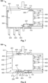
- FIGS. 1 and 2 illustrate different perspectives of a connector housing 100 of a modular electrical plug connector system according to an embodiment of an aspect of the present invention.
- FIG. 1 illustrates the connector housing 100 viewed from the top and front sides
- FIG. 2 illustrates the connector housing 100 viewed from the bottom and front sides.
- the connector housing 100 comprises a connector body 101, which is configured to receive, accommodate, and lock (in a removable manner), a plurality of plug-in connector modules of a first predetermined type.
- the connector housing 100 can accommodate and lock plug-in connector modules of said first predetermined type, and plug-in connector modules of a second predetermined type, different from the first predetermined type, could be inserted but would not be properly locked or supported within the connector housing 100 without the use of an additional structural element such as an adapter according to another aspect of the present invention.
- the connector housing 100 is configured for accommodating and locking, by default (i.e., without any additional structural element) so-called "low profile" (LP) connector modules such as, for instance, the LP connector module 300 described hereafter with reference to FIGS. 6 and 7 .
- LP low profile
- a default configuration of a connector housing according to an aspect of the present invention could be adapted to accommodate a different type of plug-in connector module.
- the connector housing 100 can then also accommodate and lock other types of modules, for instance the standard module 400 described hereafter with reference to FIG. 6 and 8 .
- the connector body 101 of the connector housing 100 comprises a plurality of adjacent module receiving passages 103 (103a, 103b, 103c, 103d, 103e) arranged side by side and, in this embodiment, configured by default to accommodate a respective LP connector module 300 therein (see FIGS. 6 and 7 ).
- the shape and size of each module receiving passage 103 is adapted to accommodate and lock therein a corresponding LP connector module 300 without requiring an additional structural element such as an adapter.
- the connector housing 100 is represented with five module receiving passages 103a-103e.
- the connector housing 100 can accommodate up to five LP connector modules 300 as desired.
- other embodiments and/or variants of a connector housing according to an aspect of the present invention could comprise more or less that five passages and, therefore, could accommodate more or less plug-in connector modules accordingly.
- each module receiving passage 103 (103a-103e) can be provided as an opening in the front side of the connector body 101 so as to extend within the connector body 101 along an insertion direction I corresponding to the direction in which a plug-in connector module should be inserted in the connector housing 100.
- each module receiving passage 103 can comprise two sidewalls 105, 107, an upper wall 109, and a bottom wall 111.
- the upper wall 109 and the bottom wall 111 comprise means for engaging and locking a connector module of the first predetermined type.
- the upper wall 109 and the bottom wall 111 both comprise a respective (upper or lower) LP module locking groove 113, 115 for engaging and locking a corresponding locking means, for instance a locking tab 305 or a locking lance 307 of an LP connector module 300, as illustrated in FIG. 7 .
- FIG. 1 a general orientation of the connector housing 100 is defined in FIG. 1 , wherein: X represents a first direction, which can be a width direction of the connector body 101; Y represents a second direction, which can be a depth direction of the connector body 101 corresponding to the insertion direction I (see FIG. 4 ) for inserting a plug-in connector module; and Z represents a third direction, which can be a height direction of the connector body 101.
- the same orientation will also be used in the other examples and embodiments described hereinafter and is illustrated, e.g., also in FIGS. 4 , 9 , and 16 .
- the bottom part of the connector housing 100 may be a part configured for being attached to a printed circuit board (PCB).
- PCB printed circuit board
- the connector housing 100 can also comprise a front protruding portion 117, visible in FIGS. 1 and 2 , which can protrude from the front side of the connector body 101.
- the front protruding portion 117 can essentially surround the module receiving passages 103a-103e on three sides (a left side, an upper side, and a right side in the orientation represented on FIG. 1 ), but preferably not on a lower side of the connector body 101, so as to leave space for the downwards extending end of bent electrical contact 303 of an LP module 300 (when accommodated in a module receiving passage 103) to be connected to a PCB.
- the front protruding portion 117 of the connector housing 100 can be provided as a separate element from the connector body 101, or it can be integrally formed, e.g. molded, with the connector body 101.
- a first type of plug-in connector module that may be inserted in the connector housing 100 by default, i.e. without using an adapter, could be a low profile (LP) module, an example of which is illustrated in FIGS. 6 and 7 .
- LP module 300 can comprise a module body 301 which can be substantially box-shaped, and bent electrical contacts 303.
- An LP module 300 can, therefore, be configured for achieving electrical connectivity between connectivity elements in a substantially perpendicular manner.
- the bent electrical contacts 303 can protrude lengthwise in prolongation of the module body 301 (see FIG. 7 ).
- the bent electrical contact 303 protrude downwards from a lower part 306 of the module body 301 (see FIG. 6 ), in a substantially perpendicular manner with respect to their configuration at the backside 302 (see FIG. 7 ).
- the LP module 300 also comprises locking means such as the locking tab 305 and the locking lance 307 (or other known locking means) illustrated in FIG. 7 , which can engage the corresponding upper and lower LP module locking grooves 113, 115 in a corresponding module receiving passage 103 of the connector housing 100 so as to be locked therein.
- locking means such as the locking tab 305 and the locking lance 307 (or other known locking means) illustrated in FIG. 7 , which can engage the corresponding upper and lower LP module locking grooves 113, 115 in a corresponding module receiving passage 103 of the connector housing 100 so as to be locked therein.
- the bent electrical contacts 303 protrude from the backside 302 of the module body 301 inside a respective module receiving passage 103 and towards the backside of the connector housing 100 along the depth direction Y corresponding also to the insertion direction I (see FIG. 7 ).
- the LP module 300 could be connected, for instance, to a pluggable connector (not illustrated) comprising, in this case, female contacts mating the electrical contacts 303.
- the connector body 101 in particular the module receiving passages 103, more in particular the arrangement of the upper and lower LP module locking grooves 113, 115, is adapted so that the front side 304 of the module body 301 extends outside of the corresponding module receiving passage 103, whereby the bent electrical contacts 303 protrude from the lower part 306 of the front side 304 of the module body 301 downwards along the height direction Z (see FIGS. 6 and 7 ).
- the LP module 300 could be connected to a PCB, for instance by welding the electrical contacts 303 to corresponding contacts of the PCB (not illustrated).
- said standard module 400 can comprise a module body 401 which can be substantially box-shaped but, in particular, of smaller length (along direction Y) and of smaller height (along direction Z) than the LP module 300.
- the standard module 400 can comprise longitudinally extending electrical contacts 403 both at the backside 402 and the front side 404 of the module body 401, whereby a linear connection can be achieved between electrical connectivity elements plugged at each end of the standard module 400.
- the electrical contacts 403 of the standard module 400 can receive mating contacts of mating pluggable electrical connectors (not illustrated) on the backside 402 and/or on the front side 404 of the module body 401 along the insertion direction I (i.e., along the depth direction Y in the orientation illustrated in FIG. 1 ).
- the electrical contacts 403 are represented as male electrical contacts, but it is understood that this aspect is not limiting for the scope of the present invention, in particular due to the modularity of the system.
- the electrical contacts 403 could be female electrical contacts without departing from the scope of the present invention.
- the standard module 400 can comprise locking means for locking the same within a module receiving passage of the connector housing of a modular electrical plug connector system.
- the standard module 400 can comprise upper and lower locking tabs 405, 407 (or locking lances, or the like).
- the front protruding portion 117 can be provided at an inner surface thereof with locking means arranged and configured for engaging corresponding (upper) locking means of a standard module 400.
- the front protruding portion 117 can comprise an upper standard module locking groove 119, as illustrated in FIG. 2 , which can be arranged and configured for engaging the upper locking tab 405 of a standard module 400, as will be explained hereafter (see FIG. 8 ).
- the connector housing 100 comprises an adapter receiving interface which is arranged and configured so as to receive, in a removable manner, an adapter for supporting the standard module 400 in at least one of the module receiving passages 103 and, in combination with the upper standard module locking groove 119, locking the standard module 400 in a module receiving passage 103.
- an adapter receiving interface which is arranged and configured so as to receive, in a removable manner, an adapter for supporting the standard module 400 in at least one of the module receiving passages 103 and, in combination with the upper standard module locking groove 119, locking the standard module 400 in a module receiving passage 103.
- a corresponding adapter receiving interface can be provided in each module receiving passage 103. In the illustrated embodiments (see FIGS.
- each adapter receiving interface can be provided preferably towards the front opening of a corresponding module receiving passage 103, here in particular, as an adapter receiving portion 121 which can be a recessed portion of the bottom wall 111 of the module receiving passage 103, and can further comprise an adapter locking tab 123.
- FIG. 3 illustrates, according to an embodiment of another aspect of the present invention, an adapter 200 for supporting and locking an electrical connector module in the connector housing of a modular electrical plug connector system.
- the adapter 200 is configured, in particular, for engaging the adapter receiving portion 121 and adapter locking tab 123 of a module receiving passage 103 of the connector housing 100 of the embodiments described above.
- the adapter 200 comprises an adapter body 201 with a first end portion defining a connector interface engaging portion 203, which is a portion thereof arranged and configured for engaging the adapter receiving interface of a module receiving passage 103 of the connector housing 100. Furthermore, the adapter body 201 comprises a second end portion defining a module supporting portion 205, which is a portion thereof arranged and configured for supporting and locking a standard module 400 when used in combination with the connector housing 100.
- the connector interface engaging portion 203 and the module supporting portion 205 can extend essentially along the same direction, which can correspond to the insertion direction I (or the depth direction Y) when the adapter 200 is mounted in the connector housing 100.
- the connector interface engaging portion 203 is designed to fit in a recessed adapter receiving portion 121 and comprises a connector interface locking slot 207, which is arranged and configured for engaging a corresponding adapter locking tab 123 of any one of the module receiving passages 103 (103a-103e).
- the module supporting portion 205 comprises a lower standard module locking slot 209 for engaging the lower locking tab 407 of a standard module 400 inserted in a module receiving passage 103 (see FIG. 8 ).
- the module supporting portion 205 can be shaped in accordance with the standard module 400 and, for instance, comprise at least one slanted portion 211 between the connector interface engaging portion 203 and the module supporting portion 205.
- the module supporting portion 205 can end in another slanted portion 213.
- the adapter 200 could be made of metal or, alternatively, of a plastic material.
- FIG. 4 illustrates, in particular, an embodiment of a modular electrical plug connector system according to an aspect of the present invention, in which the adapter 200 is about to be engaged with the adapter receiving interface of the module receiving passage 103a.
- FIG. 5 illustrates the modular electrical plug connector system with the adapter 200 being mounted in the module receiving passage 103a.
- the connector housing 100 which is configured for accommodating and locking one or more LP modules 300 by default, can now also be used for module configurations including one or more standard modules 400, as the adapter 200 is positioned so as to properly support and lock a standard module 400 in a desired module receiving passage 103 as further illustrated in FIGS. 6 and 8 .
- a standard module 400 When a standard module 400 is accommodated in one of the module receiving passages 103, for instance in the module receiving passage 103a as illustrated in FIG. 6 , with the adapter 200 having being positioned therein in advance like in FIG. 5 , the portion of the standard module body 401 projecting out of the module receiving passage 103a is supported by the module supporting portion 205 of the adapter 200, as can be seen in FIG. 8 . As also illustrated in FIG. 8 , the upper locking tab 405 of the standard module 400 is engaged in the upper standard module locking groove 119, and the lower locking tab 407 is engaged in the lower standard module locking slot 209 of the adapter 200 positioned in the adapter receiving portion 121.
- FIGS. 9 to 12 Further embodiments of aspects of the present invention will now be described with reference, in particular, to FIGS. 9 to 12 .
- FIGS. 9 and 11 show different perspectives of a modular electrical plug connector system according to an embodiment of an aspect of the present invention, with variants of the embodiments and aspects described above.
- FIG. 9 illustrates the system viewed from the top and front sides
- FIG. 11 illustrates the same system viewed from the bottom and front sides.
- the connector system of the embodiments illustrated in FIGS. 9 and 11 comprises a connector housing 500 which, like the connector housing 100 of the previous embodiments, has a connector body 501 configured to receive, accommodates, and lock (in a removable manner), a plurality of plug-in connector modules of a first predetermined type.
- the connector housing 500 shares essentially all the features and functions described above in respect of the connector housing 100, except that the adapter receiving interface is realized according to a variant of an aspect of the present invention.
- the connector housing 500 is also configured for accommodating and locking, by default (i.e., without any additional structural element), one or more LP modules 300.
- a default configuration of a connector housing according to an aspect of the present invention could be adapted to accommodate a different type of plug-in connector module.
- the connector housing 500 when used in combination with a removable adapter according to another aspect of the present invention, in particular with the adapter 600 detailed in FIG. 10 , the connector housing 500 can then also accommodate and lock standard module such as the standard module 400 described above.
- the connector housing 500 comprises a connector body 501, a plurality of module receiving passages 503 (503a, 503b, 503c, 503d, 503e) having side walls 505, 507, upper and bottom walls 509, 511, upper and lower LP module locking grooves 513, 515, as well as a front protruding portion 517 provided with an upper standard module locking groove 519, which are essentially the same as corresponding features of the connector housing 100 of the embodiments described above, namely the connector body 101, the module receiving passages 103 (including sidewalls 105, 107, upper and bottom walls 109, 111, upper and lower LP module locking grooves 113, 115), and the front protruding portion 117 provided with the upper standard module locking groove 119. Details regarding these features can be found in the description above.
- each module receiving passage 503 (503a-503e) is also adapted to accommodate and lock therein a corresponding LP connector module 300 without requiring an additional structural element such as an adapter.
- the connector housing 500 is represented with an LP connector module 300 accommodated and locked, in particular, in the module receiving passage 503e.
- the upper and lower LP module locking grooves 513, 515 are engaged and locked with the locking tab 305 and the locking lance 307 of the LP connector module 300, as described above, in particular, with reference to FIG. 7 .
- the LP connector module 300 could have been accommodated and locked in any one of the other module receiving passages 503a-503d in the same manner, i.e. without using an additional structural element.
- the illustrated connector housing 500 could accommodate up to five LP connector modules 300, other embodiments and/or variants of a connector housing according to an aspect of the present invention could comprise more or less that five passages and, therefore, could accommodate more or less plug-in connector modules accordingly.
- the front protruding portion 517 is also provided, at an inner surface thereof, with locking means arranged and configured for engaging corresponding (upper) locking means of a standard module 400.
- the upper standard module locking groove 519 of the front protruding portion 517 of the connector housing 500 can be arranged and configured for engaging the upper locking tab 405 of a standard module 400.
- the connector housing 500 comprises an adapter receiving interface which is arranged and configured so as to receive, in a removable manner, an adapter for supporting the standard module 400 in at least one of the module receiving passages 503 and, in combination with the upper standard module locking groove 519, locking the standard module 400 in said module receiving passage 503.
- an adapter receiving interface can be provided, preferably, in each module receiving passage 503 (503a-503e).
- each adapter receiving interface is here also provided preferably towards the front opening of a corresponding module receiving passage 503, in the illustrated embodiments (see FIG. 9 , 11, and 12 ), in the connector housing 500, the adapter receiving interface is provided as an adapter receiving slot 521 in the bottom wall 511 of the module receiving passage 503.
- FIG. 10 illustrates, according to an embodiment of a variant of another aspect of the present invention, an adapter 600 for supporting and locking an electrical connector module in the connector housing of a modular electrical plug connector system.
- the adapter 600 of this embodiment is configured, in particular, for engaging the adapter receiving slot 521 of a module receiving passage 503 of the connector housing 500.
- the adapter 600 comprises an adapter body 601 with a first end portion defining a connector interface engaging portion 603, which is a portion thereof arranged and configured for engaging the adapter receiving interface, i.e. here the adapter receiving slot 521, of any one of the module receiving passages 503 (503a-503e) of the connector housing 500.
- the adapter body 601 comprises a second end portion defining a module supporting portion 605, which is a portion thereof arranged and configured for supporting and locking a standard module 400 when used in combination with the connector housing 500.
- the connector interface engaging portion 603 and the module supporting portion 605 can extend essentially perpendicularly to one another.
- the module supporting portion 605 extends essentially along the insertion direction I (or the depth direction Y), and the connector interface engaging portion 603 extends essentially downward along the height direction Z (see FIG. 9 ).
- the connector interface engaging portion 603 of the adapter 600 is designed to be inserted in any one of the adapter receiving slots 521 and locked with the same.
- the connector interface engaging portion 603 comprises a resiliently deflectable connector interface locking tab 607 (or locking lance), which is arranged and configured for returning to its initial position once the connector interface engaging portion 603 has been properly inserted through the adapter receiving slot 521 of a module receiving passage 503 so as to achieve the locking.
- the module supporting portion 605 of the adapter 600 comprises a lower standard module locking slot 609 for engaging the lower locking tab 407 of a standard module 400 inserted in a module receiving passage 503 (see FIGS. 10 and 12 ).
- a standard module 400 is accommodated in one of the module receiving passages 503, for instance in the module receiving passage 503a as illustrated in FIGS. 9 and 11 , with the adapter 600 having being positioned therein in advance, the portion of the standard module body 401 projecting out of the module receiving passage 503a is supported by the module supporting portion 605 of the adapter 600, as can be seen, for instance, in FIG. 11 .
- the upper locking tab 405 of the standard module 400 is engaged in the upper standard module locking groove 519
- the lower locking tab 407 is engaged in the lower standard module locking slot 609 of the adapter 600 inserted in the adapter receiving slot 521.
- the module supporting portion 605 can also be shaped in accordance with the standard module 400 and, for instance, comprise at least one slanted portion 611 between the connector interface engaging portion 603 and the module supporting portion 605.
- the module supporting portion 605 can also end in another slanted portion 613.
- the adapter 600 could be made of metal or, alternatively, of a plastic material.
- FIGS. 9 and 11 illustrate an embodiment of a modular electrical plug connector system according to an aspect of the present invention, showing a standard module 400 accommodated and locked in the module receiving passage 503a by means of an adapter 600 inserted in the corresponding adapter receiving slot 521, while an LP module 300 is accommodated and locked in the module receiving passage 503e.
- FIGS. 9 and 11 also show a second adapter 600 about to be inserted in the adapter receiving slot 521 of the module receiving passage 503b, and a third adapter 600 inserted in the corresponding adapter receiving slot 521 of the module receiving passage 503c.
- another standard module 400 could be accommodated and locked, for instance, in the module receiving passage 503c and potentially also in the module receiving passage 503b, while the module receiving passage 503d is left free and, therefore, could receive another LP module 300 (or another standard module 400 with a corresponding adapter 600).
- FIGS. 13 to 17 Further embodiments of aspects of the present invention will now be described, in particular, with reference, in particular, to FIGS. 13 to 17 .
- FIGS. 13 and 14 illustrate different perspectives of an adapter 800 for supporting and locking an electrical connector module in the connector housing of a modular electrical plug connector system, according to another embodiment of an aspect of the present invention.
- the adapter 800 is configured for engaging the adapter receiving interface in a module receiving passage in a modular electrical plug connector system.
- the adapter 800 could be configured for engaging the adapter receiving interface, i.e. the adapter receiving slot 721 of the connector housing describing the previous embodiments.
- the adapter 800 is configured for engaging, in particular, the adapter receiving interface of a module receiving passage 703 of a connector housing 700 according to an embodiment of another aspect of the present invention.
- the adapter 800 of this embodiment comprises an adapter body 801 with a first end portion defining a connector interface engaging portion 803, which is, as described above, a portion thereof arranged and configured for engaging the adapter receiving interface of a connector housing according to an aspect of the present invention, in particular the adapter receiving interface of any one of the module receiving passages 703 (703a-703e) of the connector housing 700 (see FIGS. 16 and 17 ).
- the adapter body 801 comprises a second end portion defining a module supporting portion 805, which is a portion thereof arranged and configured for supporting and locking a predetermined type of plug-in connector module that could otherwise not be properly accommodated and locked in a module receiving passage 703 of the connector housing 700.
- the adapter 800 is used for supporting and locking a standard module 400 in a desired module receiving passage 703 of the connector housing 700.
- the connector interface engaging portion 803 of the adapter 800 can comprise two fixed connector interface locking tabs 807 which protrude downwards from the end portion of the connector interface engaging portion 803, and a resiliently deflectable connector housing locking lance 808 which can also protrude downwards (along the direction Z in the orientation illustrated, e.g., in FIG. 16 ), facing the connector interface locking tabs 807.
- the adapter 800 can further comprise a locking lance deflection space 810 (visible in FIGS. 14 and 17 ), configured and arranged for allowing deflection of the connector housing locking lance 808.
- the module supporting portion 805 of the adapter 800 comprises a lower standard module locking groove 809, which is arranged and configured for engaging the lower locking tab 407 of a standard module 400 inserted in a module receiving passage 703 of the connector housing 700 (see FIG. 17 ).
- the lower standard module locking groove 809 is provided as a recess of the upper surface of the module supporting portion 805.
- the surface of the module supporting portion 805 of the adapter 800 of this embodiment can be shaped with a stepped portion 813, as shown in FIG. 13 .
- the adapter body 801 can further comprise a supporting member 806 protruding downwards from the module supporting portion 805.
- the supporting member 806 is a cylinder-shaped foot which can provide improved support by resting on a PCB to which the connector housing 700 could be attached. It is understood, however, that the supporting member 806 could have other shapes in variants of this embodiment without departing from the present invention.
- the adapter 800 of this embodiment could be made of metal or of a plastic material.
- a plastic material is preferred, as it would reduce the production cost of the adapter 800.
- known molding processes could be used for manufacturing the adapter 800.
- FIG. 15 illustrates an embodiment of an adapter strip 900 according to an aspect of the present invention, which consists of a side-by-side arrangement of a plurality of adapters 800 (800a, 800b, 800c, 800d, 800e).
- the adapter strip 900 could be obtained by known molding processes which would allow reducing the production costs compared to adapters made of metal. In any case, this would also allow reducing production costs with respect to known modular electrical plug connector systems which need to design a specific bottom plate for the connector housing every time that a plug-in connector module configuration is changed.
- the adapter strip 900 could be molded as an integral piece, with a plurality of adapters 800 joined to one another.
- one adapter strip 900 could be formed of at least as many adapters 800 as the number of module receiving passages 703 in a connector housing 700.
- the connector housing 700 comprises five module receiving passages 703 (703a-703e)
- the adapter strip 900 illustrated in FIG. 15 is formed of five adapters 800 (800a-800e). It is understood, however, that an adapter strip could consist of more or less than five adapters without departing from the scope of the present invention.
- FIG. 16 illustrates a modular electrical plug connector system according to an embodiment of an aspect of the present invention.
- the connector system comprises a connector housing 700 which, like the connector housings 100, 500 of the previous embodiments, has a connector body 701 configured to receive, accommodates, and lock (in a removable manner), a plurality of plug-in connector modules of a first predetermined type.
- the connector housing 700 shares essentially all the features and functions described above in respect of the connector housings 100, 500, except that the adapter receiving interface is realized according to yet another variant of an aspect of the present invention.
- the connector housing 700 of this embodiment is also configured for accommodating and locking, by default (i.e., without any additional structural element), one or more LP modules 300 using the features already described above for the previous embodiments.
- a default configuration of a connector housing according to an aspect of the present invention could be adapted to accommodate a different type of plug-in connector module.
- the connector housing 700 when the connector housing 700 is used in combination with a removable adapter according to another aspect of the present invention, in particular with the adapter 800 described with reference to FIGS. 13 and 14 , and/or with an adapter strip according to another aspect of the present invention, in particular with the adapter strip 900 described with reference to FIG. 15 , the connector housing 700 can then also accommodate and lock standard module such as the standard module 400 described in the previous embodiments.
- the connector housing 700 comprises a connector body 701, a plurality of module receiving passages 703 (703a, 703b, 703c, 703d, 703e) having side walls 705, 707, upper and bottom walls 709, 711, upper and lower LP module locking grooves 713, 715, as well as a front protruding portion 717 provided with an upper standard module locking groove 719, which correspond essentially to the features already described in the previous embodiments for the connector housings 100, 500, namely the connector bodies 101, 501, the module receiving passages 103, 503 (including sidewalls 105, 107 and 505, 507, upper and bottom walls 109, 111 and 509, 511, upper and lower LP module locking grooves 113, 115 and 513, 515), and the respective front protruding portion 117, 517 provided with a upper standard module locking groove 119, 519. Details regarding these features can be found in the description above.
- an LP connector module 300 can be accommodated and locked in any one of the module receiving passages 703 (703a-703e) without any additional structural element such as an adapter.
- the upper and lower LP module locking grooves 713, 715 would be engaged and locked with the locking tab 305 and the locking lance 307 of the LP connector module 300, as described above, in particular, with reference to FIG. 7 .
- the illustrated connector housing 700 could accommodate up to five LP connector modules 300, other embodiments and/or variants of a connector housing according to an aspect of the present invention could comprise more or less that five passages and, therefore, could accommodate more or less plug-in connector modules accordingly.
- the front protruding portion 717 of the connector housing 700 of the embodiment illustrated in FIGS. 16 and 17 can also be provided, at an inner surface thereof, with locking means arranged and configured for engaging corresponding (upper) locking means of a standard module 400.
- an upper standard module locking groove 719 is provided in the front protruding portion 717 of the connector housing 700 and is arranged and configured for engaging the upper locking tab 405 of a standard module 400.
- the connector housing 700 in order to prepare the connector housing 700 for accommodating and locking a standard module 400, the connector housing 700 comprises an adapter receiving interface which is arranged and configured so as to receive, in a removable manner, an adapter for supporting the standard module 400 in at least one of the module receiving passages 703 and, in combination with the upper standard module locking groove 719, locking the standard module 400 in said module receiving passage 703.
- a corresponding adapter receiving interface can be provided, preferably, in each module receiving passage 703 (703a-703e).
- each adapter receiving interface is provided preferably towards the front opening of a corresponding module receiving passage 703.
- the adapter receiving interface is provided as an adapter receiving groove 721 in the bottom wall 711 of each module receiving passage 703, and further comprises an adapter locking lip 723 protruding from the front side of the connector body 701, below the bottom wall 711 of each module receiving passage 703.
- FIG. 16 also illustrates an embodiment of a modular electrical plug connector system according to an aspect of the present invention, showing the connector housing 700 and the adapter strip 900.
- the adapter strip 900 is formed from five adapters 800 (800a-800e), which are joined to each other in a cleavable or severable manner.
- one adapter 800a has been separated from the adapter strip 900 and can now be attached to an adapter receiving interface over module receiving passage 703 of the connector housing 700 in order to provide support and locking functionality for a standard module 400, like in FIG. 17 .
- an adapter 800 (800a) is presented in front of the module receiving passage 703c, and the adapter strip 900, therefore, not only comprises the remaining four adapters 800b-800e.
- an adapter strip such as the adapter strip 900, formed by as many adapters 800 as required, could be used directly, without being cleaved, in order to achieve a configuration with multiple standard modules 400 at once.
- adapter strips comprising any required number of adapters 800 joined side-by-side could be attached directly to several module receiving passages 703 at the same time.
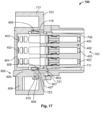
- FIG. 17 illustrates an embodiment in which a standard module 400 is accommodated and locked in a module receiving passage 703 by means of an adapter 800 engaged with a corresponding adapter receiving interface.
- the connector interface locking tabs 807 are engaged in the adapter receiving groove 721 of the bottom wall 711 of the module receiving passage 703.
- the connector housing locking lance 808, which can be deflected in the locking lance deflection space 810 during the mounting process, is now locked with the adapter locking lip 723 at the front side of the adapter body 701.
- the upper locking tab 405 of the standard module 400 is engaged in the upper standard module locking groove 719, and the lower locking tab 407 is engaged in the lower standard module locking groove 809 of the adapter 800.
- the supporting member 806 provides improved mechanical support for the standard module 400 with respect to the adapters 200, 600 of the previous embodiments (see, in particular, FIGS. 8 and 12 ). Furthermore, with the supporting member 806, the manipulation and, therefore, mounting of the adapter 800 on an adapter receiving interface of the connector housing 700 is facilitated, in particular, with respect to the adapters 200, 600 of the previous embodiments.
- one aspect of the present invention provides a connector housing of a modular electrical plug connector system (e.g., one of the connector housings 100, 500, 700), which can be manufactured in a standard and simple manner (e.g., by molding) and wherein a first predetermined type of plug-in connector module (e.g., an LP module 300) can be accommodated and locked by default.
- a first predetermined type of plug-in connector module e.g., an LP module 300
- a second, different, predetermined type of plug-in connector module needs to be used (e.g., a standard module 400)
- an adapter e.g. one of the adapters 200, 600, 800
- adapter receiving interface of a connector housing according to the former aspect of the invention in order to support and lock said second predetermined type of plug-in connector module.
- an adapter according to the latter aspect of the invention could be made of metal or of a plastic material.
- another aspect of the present invention provides an adapter strip (e.g., adapter strip 900), which facilitates and standardizing even more the production of some variants of the adapter.
Landscapes
- Details Of Connecting Devices For Male And Female Coupling (AREA)
- Connector Housings Or Holding Contact Members (AREA)
Description
- The present invention relates to the field of modular electrical plug connector systems comprising a connector housing accommodating different types of plug-in connector modules.
- Modular electrical plug connector systems typically comprise a connector housing, which can also be designated as "module rack" or "module mount", accommodating a plurality of plug-in connector modules as shown in
DE 10 2015 114 814 A1 . In these systems, the connector housing usually comprises fixed slots or passages designed to receive the plug-in connector modules in a predetermined arrangement, which can vary depending on the connectivity requirements of the application. - In some electrical connectivity applications, for instance in automotive or aeronautical applications, it is common to use configurations comprising different types of connector modules disposed in a same connector housing. For instance, one type of plug-in connector module, which can be designated as "standard module" hereafter, can comprise a plurality of (male or female) contacts configured for receiving a plurality of corresponding wire-like (female or male, respectively) crimp contacts, in particular, along an insertion direction corresponding to the direction along which the plug-in connector module is disposed in the connector housing. Furthermore, another type of plug-in connector module, which can be designated as "low profile (LP) module" hereafter, can comprise bent contacts configured to be soldered to a printed circuit board, in particular, along a direction substantially perpendicular to the direction along which the plug-in connector module is disposed in the connector housing.
- In known modular electrical plug connector systems, since different types of connector modules, in particular standard connector modules and low profile connector modules, typically have different shapes and dimensions, the design and configuration of the slots or passages of the connector housing are usually fixed during the manufacturing process, in accordance with the desired configuration and particular arrangement of the plug-in connector modules.
- Thus, in known modular electrical plug connector systems, it is usually not possible to dispose a connector module of a given type, e.g. a standard module, in a slot or passage designed for a connector module of a different type, e.g. a low profile module, without redesigning at least part of the connector housing. In other words, a rearrangement of plug-in connector modules of different types in a given connector housing is usually not possible without redesigning at least part of the connector housing. Typically, at least a bottom plate (or front side) of the connector housing, which is a plate (or side) of the connector housing supporting the different plug-in modules, must be redesigned for each desired configuration.
- Accordingly, a drawback of known modular connector systems is that it is difficult to standardize the manufacturing process of the connector housing, in particular, in a manner that would be suitable for providing different configurations of connector modules without having to provide a different bottom plate of the connector housing for each configuration. This results in high manufacturing costs, especially for connectivity applications in harsh environments (i.e., environments submitted to intense vibrations, high temperatures, or the like), where at least the bottom plate (or front side) of the connector housing may need to be made of metal instead of a plastic material.
-
US 2014/0045373 A1 andWO 2014/139699 A1 disclose modular electrical plug connector assemblies for control units in motor vehicles, wherein an assembly comprises a module rack (module mount, or module carrier) and at least two different types of plug-in connector modules which can accommodate respective electrical plug connectors. The connector modules are arranged in respective specifically designed and dedicated slots or passages of a bottom plate (or front side) of the module rack and can only be positioned relative to each other in a predetermined manner. Furthermore, the connector modules are inseparably connected to the module rack by a joining process (e.g., welding or gluing). - Thus, in these known modular electrical connector assemblies, the configuration of the connector modules in the module rack is determined during the manufacturing process, and different configurations require different designs of the module rack, in particular of the bottom plate (or front side) of the module rack.
- In view of the above, as an alternative to known existing solutions, it is desirable to provide an improved modular electrical plug connector system that would allow using different connector module configurations without having to redesign a new bottom plate of the connector housing for each configuration. It is also desirable to provide an improved connector housing that could be manufactured in a standardized manner and that could be used for different connector module configurations in a simple manner. In particular, it is desirable to provide an improved connector housing and corresponding modular electrical plug connector system, wherein a same slot or passage of the connector housing could be used for supporting and locking different types of connector modules.
- The above-mentioned problems are solved by the various aspects of the present invention defined by the independent claim.
- Optional features of the invention are described in the dependent claims and will be explained hereafter more in detail.
- According to one aspect, the present invention provides a connector housing of a modular electrical plug connector system according to claim 1.
- Thus, the present invention provides a modular connector housing with which it is possible to use more than one predetermined module in a plurality of different configurations without having to redesign a bottom plate of the connector housing. For instance, the connector housing can be configured to accommodate so-called "low profile" modules by default (which can be a first predetermined type). Then, in order to also accommodate standard modules (which can be a second predetermined type), which have a different size, instead of redesigning a bottom plate of the connector housing every time a new configuration is required, it is possible to use one or more standardized adapters, which can be manufactured for reduced costs and can be attached to a predefined adapter receiving interface of a module receiving passage of the connector housing, as necessary. In this way, it is also possible to standardize the manufacturing process of the connector housing. In further preferred embodiments, said adapter receiving interface can comprise at least one of a locking tab, a groove, a slot, and an opening, or a combination thereof.
- According to another aspect, the present invention also provides a modular electrical plug connector system comprising a connector housing, and at least one adapter, and/or an adapter strip according to claim 4.
- An adapter for supporting and locking an electrical connector module in a connector housing of a modular electrical plug connector system, in particular in a passage of an electrical connector housing according to the previous aspect or any of its variants, is provided. The adapter comprises an adapter body. A first portion of the adapter body is configured for engaging, in a removable manner, an adapter receiving interface of a connector housing of a modular electrical plug connector system, in particular of a passage of an electrical connector housing according to the previous aspect or any of its variants. A second portion of the adapter body is configured for supporting and locking an electrical connector module, in particular an electrical connector module accommodated in a passage of an electrical connector housing according to the previous aspect or any of its variants.
- Thus, an adapter to be used in combination with a connector housing of a modular electrical plug connector system is provided in order to accommodate and lock plug-in connector modules which otherwise cannot be properly supported and/or locked in the connector housing. Instead of redesigning a bottom plate for the connector housing, an adapter can be arranged in any module receiving passage of the connector housing without effort and in a simple manner. It is also possible to change configurations of plug-in connector modules in the connector housing rapidly and without the need of special tools and without the need to redesign elements of the connector housing for each new configuration.
- In preferred embodiments, said first portion of the adapter body can comprise at least one of a slot, an opening, a locking tab, and a locking lance, or a combination thereof. Thus, it is possible to improve the level of support for the adapter with respect to a module receiving passage of a connector housing when the adapter is mounted to the adapter receiving interface.
- In preferred embodiments, said second portion of the adapter body can comprise at least one of a groove, and a slot, or a combination thereof. Thus, it is possible to improve the locking functionality with a plug-in connector module of the second predetermined type.
- In some embodiments, said first portion can be substantially perpendicular to said second portion. Thus, it is possible to increase the support provided to a plug-in connector module of the second predetermined type.
- In preferred embodiments, said second portion can be slanted and/or or stepped. With this feature, it is possible to increase the support provided to a plug-in connector module of the second predetermined type, while also improving the ease of manipulation of the adapter.
- In preferred embodiments, the adapter body can further comprise a protrusion forming a supporting member extending from said second portion. Thus, it is possible to improve even more the support provided to a plug-in connector module of the second predetermined type, while also improving even more the ease of manipulation of the adapter.
- In preferred embodiments, the supporting member can extend from said second portion in a substantially perpendicular manner. Thus, it is possible to improve even more the support provided to a plug-in connector module of the second predetermined type, while also improving even more the ease of manipulation of the adapter.
- In preferred embodiments, the adapter body can be made in one piece. Thus, the present invention can provide a simple solution for adapting a connector housing configured to accommodate a first predetermined type of plug-in connector modules to be used also with a second, different, type of plug-in connector modules. In particular, the adapter can be manufactured by known molding techniques, which can facilitate and reduce the manufacturing process with respect to known solutions for modular electrical plug connector systems.
- In some embodiments, the adapter body can be made of a metal or of a plastic material. Thus, it is possible to adapt the level of support and durability of an adapter as desired and as required by the application.
- Furthermore, according to another aspect, the present invention also provides an adapter strip consisting of a side-by-side arrangement of a plurality of adapters according to the previous aspect or any of its variants, wherein the adapters are joined to each other.
- Thus, the present invention also facilitates the production of variants of an adapter. Furthermore, this aspect of the present invention also provides a solution for adapting simultaneously a plurality of module receiving passages of a connector housing to be used with a plug-in connector module of the second predetermined type.
- In preferred embodiments, the adapters can be joined to each other in a cleavable or severable manner. Thus, it is possible to provide an increased level of modularity. Furthermore, the production of some variants of the adapter can be facilitated and even standardized. This solution also provides with increased adaptability, as an adapter strip can be made with as many adapters as required. Adapters can also be cleaved to form one or more smaller adapter strips, and/or one or more individual adapters.
- In short, with the present invention, each passage (or socket, or slot) of the connector housing of a modular electrical plug connector system is configured to receive a particular first type of plug-in connector module (e.g., a low profile module), and can optionally receive a removable adapter (e.g., a removable tab) in order to accommodate and lock a second, different, type of plug-in connector module (e.g., a standard module) in one or more desired passages of the connector housing. The present invention, therefore, provides a modular electrical plug connector system with improved versatility and reduced costs with respect to known solutions. In particular, with the present invention, it is no longer necessary to redesign a bottom plate for the connector housing each time a new arrangement of plug-in connector modules is desired. Thus, it is possible to (re)define any desired arrangement of plug-in connector modules, comprising modules of the first and/or second predetermined type, in a quick and simple manner.
- The invention will be described more in detail hereafter, based on advantageous embodiments described in combination with the accompanying figures, wherein:
- FIG. 1
- is a general view illustrating an exemplary embodiment of a connector housing according to an aspect of the present invention;
- FIG. 2
- is a view detailing a portion of the connector housing of the exemplary embodiment illustrated in
FIG. 1 , viewed from a different perspective; - FIG. 3
- is a general view illustrating an exemplary embodiment of an adapter according to an aspect of the present invention;
- FIG. 4
- is a general view detailing a portion of a modular electrical plug connector system in a further exemplary embodiment of an aspect of the present invention, in which an adapter according to the embodiment illustrated in
FIG. 3 is used with a connector housing according to the embodiment illustrated inFIGS. 1 and 2 ; - FIG. 5
- is another general view detailing the portion of the modular electrical plug connector system of the exemplary embodiment illustrated in
FIG. 4 , with the adapter mounted in a passage of the connector housing; - FIG. 6
- is another general view detailing the portion of the modular electrical plug connector system of the embodiment illustrated in
FIGS. 4 and5 , in a variant where a low profile module is disposed in a passage of the connector housing, while a standard module is supported and locked by the adapter in another passage of the connector housing; - FIG. 7
- is a cross-sectional side view of the variant illustrated in
FIG. 6 , showing the low profile module disposed in a passage of the connector housing; - FIG. 8
- is another cross-sectional side view of the variant illustrated in
FIG. 6 , showing the standard module and the adapter disposed in a passage of the connector housing; - FIG. 9
- is a general view illustrating another exemplary embodiment of a modular electrical plug connector system according to variants of aspects of the present invention;
- FIG. 10
- is a general view illustrating an exemplary embodiment of an adapter according to a variant of an aspect of the present invention, corresponding, in particular, to the adapters used in the embodiment illustrated in
FIG. 9 ; - FIG. 11
- is another general view of the modular electrical connector system of the exemplary embodiment illustrated in
FIG. 9 , seen from a different perspective; - FIG. 12
- is a sectional view of the exemplary modular electrical plug connector system illustrate in
FIG. 9 , detailing the standard module and the adapter disposed in a passage of the connector housing; - FIG. 13
- is a general view illustrating another exemplary embodiment of an adapter according to variants of an aspect of the present invention;
- FIG. 14
- is another general view of the adapter of the exemplary embodiment illustrated in
FIG. 13 , seen from a different perspective; - FIG. 15
- is a general view illustrating an exemplary embodiment of an adapter strip according to an aspect of the present invention;
- FIG. 16
- is a general view illustrating an exemplary embodiment of a modular electrical plug connector system according to variants of aspects of the present invention, in which an adapter according to the embodiment illustrated in
FIGS. 13 and 14 and/or an adapter strip according to the embodiment illustrated inFIG. 15 is/are used with a connector housing according to a variant of an aspect of the present invention; and - FIG. 17
- is a cross-sectional side view of an exemplary embodiment of a modular electrical plug connector system according to variants of the present invention, in particular the system according to the exemplary embodiment illustrated in
FIG. 16 , detailing a standard module supported and locked in a passage of a connector housing according to a variant of an aspect of the present invention, using an adapter according to the exemplary embodiment illustrated inFIGS. 13 and 14 , and/or an adapter strip according to the exemplary embodiment illustrated inFIG. 15 . - Advantageous exemplary embodiments of the above-mentioned aspects of the present invention will be described hereafter with reference to the accompanying figures. For the sake of brevity, the description of features already described in some embodiments may be omitted in other embodiments. Furthermore, for the sake of simplicity, the same reference signs may be used to designate the same elements if these elements are used in different embodiments.
- First embodiments of aspects of the present invention will now be described with reference, in particular, to
FIGS. 1 to 8 . -
FIGS. 1 and 2 illustrate different perspectives of aconnector housing 100 of a modular electrical plug connector system according to an embodiment of an aspect of the present invention. In particular,FIG. 1 illustrates theconnector housing 100 viewed from the top and front sides, andFIG. 2 illustrates theconnector housing 100 viewed from the bottom and front sides. In this embodiment, theconnector housing 100 comprises aconnector body 101, which is configured to receive, accommodate, and lock (in a removable manner), a plurality of plug-in connector modules of a first predetermined type. By default, theconnector housing 100 can accommodate and lock plug-in connector modules of said first predetermined type, and plug-in connector modules of a second predetermined type, different from the first predetermined type, could be inserted but would not be properly locked or supported within theconnector housing 100 without the use of an additional structural element such as an adapter according to another aspect of the present invention. - In these embodiments, the
connector housing 100 is configured for accommodating and locking, by default (i.e., without any additional structural element) so-called "low profile" (LP) connector modules such as, for instance, theLP connector module 300 described hereafter with reference toFIGS. 6 and7 . In other embodiments, however, a default configuration of a connector housing according to an aspect of the present invention could be adapted to accommodate a different type of plug-in connector module. Furthermore, as will also be described hereafter, when theconnector housing 100 is used in combination with a removable adapter according to another aspect of the present invention, in particular with theadapter 200 described hereafter with reference toFIGS. 3-5 , theconnector housing 100 can then also accommodate and lock other types of modules, for instance thestandard module 400 described hereafter with reference toFIG. 6 and8 . - In the illustrated embodiments, as can be taken in particular from
FIGS. 1 and 2 , theconnector body 101 of theconnector housing 100 comprises a plurality of adjacent module receiving passages 103 (103a, 103b, 103c, 103d, 103e) arranged side by side and, in this embodiment, configured by default to accommodate a respectiveLP connector module 300 therein (seeFIGS. 6 and7 ). In other words, the shape and size of eachmodule receiving passage 103 is adapted to accommodate and lock therein a correspondingLP connector module 300 without requiring an additional structural element such as an adapter. In the illustrated embodiments, theconnector housing 100 is represented with fivemodule receiving passages 103a-103e. Accordingly, in the illustrated embodiments, theconnector housing 100 can accommodate up to fiveLP connector modules 300 as desired. However, other embodiments and/or variants of a connector housing according to an aspect of the present invention could comprise more or less that five passages and, therefore, could accommodate more or less plug-in connector modules accordingly. - As illustrated in
FIGS. 1 and 2 , each module receiving passage 103 (103a-103e) can be provided as an opening in the front side of theconnector body 101 so as to extend within theconnector body 101 along an insertion direction I corresponding to the direction in which a plug-in connector module should be inserted in theconnector housing 100. Furthermore, eachmodule receiving passage 103 can comprise twosidewalls upper wall 109, and abottom wall 111. In this embodiment, theupper wall 109 and thebottom wall 111 comprise means for engaging and locking a connector module of the first predetermined type. For instance, in this embodiment, in eachmodule receiving passage 103, theupper wall 109 and thebottom wall 111 both comprise a respective (upper or lower) LPmodule locking groove locking tab 305 or alocking lance 307 of anLP connector module 300, as illustrated inFIG. 7 . - For the sake of clarity, a general orientation of the
connector housing 100 is defined inFIG. 1 , wherein: X represents a first direction, which can be a width direction of theconnector body 101; Y represents a second direction, which can be a depth direction of theconnector body 101 corresponding to the insertion direction I (seeFIG. 4 ) for inserting a plug-in connector module; and Z represents a third direction, which can be a height direction of theconnector body 101. The same orientation will also be used in the other examples and embodiments described hereinafter and is illustrated, e.g., also inFIGS. 4 ,9 , and16 . Furthermore, since theconnector housing 100 is configured to receiveLP connector modules 300 by default, the bottom part of theconnector housing 100 may be a part configured for being attached to a printed circuit board (PCB). Further variants of a connector housing described hereinafter may, therefore, also be configured for being attached to a PCB, but this aspect should not be viewed as being limiting for the scope of the present invention. - Furthermore, the
connector housing 100 can also comprise a front protrudingportion 117, visible inFIGS. 1 and 2 , which can protrude from the front side of theconnector body 101. For instance, thefront protruding portion 117 can essentially surround themodule receiving passages 103a-103e on three sides (a left side, an upper side, and a right side in the orientation represented onFIG. 1 ), but preferably not on a lower side of theconnector body 101, so as to leave space for the downwards extending end of bentelectrical contact 303 of an LP module 300 (when accommodated in a module receiving passage 103) to be connected to a PCB. The front protrudingportion 117 of theconnector housing 100 can be provided as a separate element from theconnector body 101, or it can be integrally formed, e.g. molded, with theconnector body 101. - As mentioned above, in the illustrated embodiments, a first type of plug-in connector module that may be inserted in the
connector housing 100 by default, i.e. without using an adapter, could be a low profile (LP) module, an example of which is illustrated inFIGS. 6 and7 . As illustrated, anLP module 300 can comprise amodule body 301 which can be substantially box-shaped, and bentelectrical contacts 303. AnLP module 300 can, therefore, be configured for achieving electrical connectivity between connectivity elements in a substantially perpendicular manner. Thus, at abackside 302 of themodule body 301, the bentelectrical contacts 303 can protrude lengthwise in prolongation of the module body 301 (seeFIG. 7 ). Furthermore, at afront side 304 of themodule body 301, the bentelectrical contact 303 protrude downwards from alower part 306 of the module body 301 (seeFIG. 6 ), in a substantially perpendicular manner with respect to their configuration at the backside 302 (seeFIG. 7 ). - As also mentioned above, the
LP module 300 also comprises locking means such as thelocking tab 305 and the locking lance 307 (or other known locking means) illustrated inFIG. 7 , which can engage the corresponding upper and lower LPmodule locking grooves module receiving passage 103 of theconnector housing 100 so as to be locked therein. - Accordingly, in the orientation illustrated in
FIG. 1 , when theLP module 300 is accommodated in amodule receiving passage 103 of theconnector housing 100 as illustrated inFIG. 6 and7 , the bentelectrical contacts 303 protrude from thebackside 302 of themodule body 301 inside a respectivemodule receiving passage 103 and towards the backside of theconnector housing 100 along the depth direction Y corresponding also to the insertion direction I (seeFIG. 7 ). In this way, at itsbackside 302, theLP module 300 could be connected, for instance, to a pluggable connector (not illustrated) comprising, in this case, female contacts mating theelectrical contacts 303. - Furthermore, the
connector body 101, in particular themodule receiving passages 103, more in particular the arrangement of the upper and lower LPmodule locking grooves front side 304 of themodule body 301 extends outside of the correspondingmodule receiving passage 103, whereby the bentelectrical contacts 303 protrude from thelower part 306 of thefront side 304 of themodule body 301 downwards along the height direction Z (seeFIGS. 6 and7 ). In this way, at itsfront side 304, theLP module 300 could be connected to a PCB, for instance by welding theelectrical contacts 303 to corresponding contacts of the PCB (not illustrated). - In the illustrated embodiments, it is also desired to accommodate and lock a plug-in connector module of a different type than the
LP module 300 in theconnector housing 100 in an interchangeable manner with the LP modules. In particular, it is desired to provide a solution for accommodating a standard module such as thestandard module 400 illustrated inFIGS. 6 and8 . As illustrated, saidstandard module 400 can comprise amodule body 401 which can be substantially box-shaped but, in particular, of smaller length (along direction Y) and of smaller height (along direction Z) than theLP module 300. Thestandard module 400 can comprise longitudinally extendingelectrical contacts 403 both at thebackside 402 and thefront side 404 of themodule body 401, whereby a linear connection can be achieved between electrical connectivity elements plugged at each end of thestandard module 400. In particular, theelectrical contacts 403 of thestandard module 400 can receive mating contacts of mating pluggable electrical connectors (not illustrated) on thebackside 402 and/or on thefront side 404 of themodule body 401 along the insertion direction I (i.e., along the depth direction Y in the orientation illustrated inFIG. 1 ). In the illustrated embodiments, theelectrical contacts 403 are represented as male electrical contacts, but it is understood that this aspect is not limiting for the scope of the present invention, in particular due to the modularity of the system. Thus, in other embodiments, theelectrical contacts 403 could be female electrical contacts without departing from the scope of the present invention. - In addition, the
standard module 400 can comprise locking means for locking the same within a module receiving passage of the connector housing of a modular electrical plug connector system. For instance, as illustrated inFIG. 8 , thestandard module 400 can comprise upper andlower locking tabs 405, 407 (or locking lances, or the like). - In order to prepare the
connector housing 100 for accommodating and locking astandard module 400, thefront protruding portion 117 can be provided at an inner surface thereof with locking means arranged and configured for engaging corresponding (upper) locking means of astandard module 400. Thus, in the illustrated embodiments, thefront protruding portion 117 can comprise an upper standardmodule locking groove 119, as illustrated inFIG. 2 , which can be arranged and configured for engaging theupper locking tab 405 of astandard module 400, as will be explained hereafter (seeFIG. 8 ). - Furthermore, also in order to prepare the
connector housing 100 for accommodating and locking astandard module 400, theconnector housing 100 comprises an adapter receiving interface which is arranged and configured so as to receive, in a removable manner, an adapter for supporting thestandard module 400 in at least one of themodule receiving passages 103 and, in combination with the upper standardmodule locking groove 119, locking thestandard module 400 in amodule receiving passage 103. As illustrated, in particular, inFIG. 1 , for maximum modularity, a corresponding adapter receiving interface can be provided in eachmodule receiving passage 103. In the illustrated embodiments (seeFIGS. 1 ,4 ,5 , and8 ), each adapter receiving interface can be provided preferably towards the front opening of a correspondingmodule receiving passage 103, here in particular, as anadapter receiving portion 121 which can be a recessed portion of thebottom wall 111 of themodule receiving passage 103, and can further comprise anadapter locking tab 123. -
FIG. 3 illustrates, according to an embodiment of another aspect of the present invention, anadapter 200 for supporting and locking an electrical connector module in the connector housing of a modular electrical plug connector system. As further illustrated inFIGS. 4 and5 , theadapter 200 is configured, in particular, for engaging theadapter receiving portion 121 andadapter locking tab 123 of amodule receiving passage 103 of theconnector housing 100 of the embodiments described above. - Thus, in these embodiments and as illustrated in
FIG. 3 , theadapter 200 comprises anadapter body 201 with a first end portion defining a connectorinterface engaging portion 203, which is a portion thereof arranged and configured for engaging the adapter receiving interface of amodule receiving passage 103 of theconnector housing 100. Furthermore, theadapter body 201 comprises a second end portion defining amodule supporting portion 205, which is a portion thereof arranged and configured for supporting and locking astandard module 400 when used in combination with theconnector housing 100. In these embodiments, the connectorinterface engaging portion 203 and themodule supporting portion 205 can extend essentially along the same direction, which can correspond to the insertion direction I (or the depth direction Y) when theadapter 200 is mounted in theconnector housing 100. - Thus, as illustrated in
FIGS. 4 and5 , the connectorinterface engaging portion 203 is designed to fit in a recessedadapter receiving portion 121 and comprises a connectorinterface locking slot 207, which is arranged and configured for engaging a correspondingadapter locking tab 123 of any one of the module receiving passages 103 (103a-103e). - Furthermore, the
module supporting portion 205 comprises a lower standardmodule locking slot 209 for engaging thelower locking tab 407 of astandard module 400 inserted in a module receiving passage 103 (seeFIG. 8 ). In addition, in order to provide better support for thestandard module 400, themodule supporting portion 205 can be shaped in accordance with thestandard module 400 and, for instance, comprise at least oneslanted portion 211 between the connectorinterface engaging portion 203 and themodule supporting portion 205. Optionally, in order to more easily manipulate theadapter 200, themodule supporting portion 205 can end in another slantedportion 213. Furthermore, depending on how much support and/or durability is needed, theadapter 200 could be made of metal or, alternatively, of a plastic material. -
FIG. 4 illustrates, in particular, an embodiment of a modular electrical plug connector system according to an aspect of the present invention, in which theadapter 200 is about to be engaged with the adapter receiving interface of themodule receiving passage 103a. In turn,FIG. 5 illustrates the modular electrical plug connector system with theadapter 200 being mounted in themodule receiving passage 103a. With this latter configuration of the modular electrical plug connector system, theconnector housing 100, which is configured for accommodating and locking one ormore LP modules 300 by default, can now also be used for module configurations including one or morestandard modules 400, as theadapter 200 is positioned so as to properly support and lock astandard module 400 in a desiredmodule receiving passage 103 as further illustrated inFIGS. 6 and8 . - When a
standard module 400 is accommodated in one of themodule receiving passages 103, for instance in themodule receiving passage 103a as illustrated inFIG. 6 , with theadapter 200 having being positioned therein in advance like inFIG. 5 , the portion of thestandard module body 401 projecting out of themodule receiving passage 103a is supported by themodule supporting portion 205 of theadapter 200, as can be seen inFIG. 8 . As also illustrated inFIG. 8 , theupper locking tab 405 of thestandard module 400 is engaged in the upper standardmodule locking groove 119, and thelower locking tab 407 is engaged in the lower standardmodule locking slot 209 of theadapter 200 positioned in theadapter receiving portion 121. - Further embodiments of aspects of the present invention will now be described with reference, in particular, to
FIGS. 9 to 12 . -
FIGS. 9 and11 show different perspectives of a modular electrical plug connector system according to an embodiment of an aspect of the present invention, with variants of the embodiments and aspects described above. In particular,FIG. 9 illustrates the system viewed from the top and front sides, andFIG. 11 illustrates the same system viewed from the bottom and front sides. - The connector system of the embodiments illustrated in
FIGS. 9 and11 comprises aconnector housing 500 which, like theconnector housing 100 of the previous embodiments, has aconnector body 501 configured to receive, accommodates, and lock (in a removable manner), a plurality of plug-in connector modules of a first predetermined type. Theconnector housing 500 shares essentially all the features and functions described above in respect of theconnector housing 100, except that the adapter receiving interface is realized according to a variant of an aspect of the present invention. Thus, as can be seen inFIGS. 9 and11 , like theconnector housing 100 of the previous embodiments, theconnector housing 500 is also configured for accommodating and locking, by default (i.e., without any additional structural element), one ormore LP modules 300. As mentioned above, in other embodiments, a default configuration of a connector housing according to an aspect of the present invention could be adapted to accommodate a different type of plug-in connector module. - Furthermore, as will also be described hereafter also with reference to
FIG. 12 , when theconnector housing 500 is used in combination with a removable adapter according to another aspect of the present invention, in particular with theadapter 600 detailed inFIG. 10 , theconnector housing 500 can then also accommodate and lock standard module such as thestandard module 400 described above. - In these embodiments, as can be taken from
FIGS. 9 and11 , theconnector housing 500 comprises aconnector body 501, a plurality of module receiving passages 503 (503a, 503b, 503c, 503d, 503e) havingside walls bottom walls module locking grooves front protruding portion 517 provided with an upper standardmodule locking groove 519, which are essentially the same as corresponding features of theconnector housing 100 of the embodiments described above, namely theconnector body 101, the module receiving passages 103 (includingsidewalls bottom walls module locking grooves 113, 115), and the front protrudingportion 117 provided with the upper standardmodule locking groove 119. Details regarding these features can be found in the description above. - Thus, the shape and size of each module receiving passage 503 (503a-503e) is also adapted to accommodate and lock therein a corresponding
LP connector module 300 without requiring an additional structural element such as an adapter. In the illustrated embodiments, theconnector housing 500 is represented with anLP connector module 300 accommodated and locked, in particular, in themodule receiving passage 503e. Thus, in themodule receiving passage 503e, the upper and lower LPmodule locking grooves locking tab 305 and thelocking lance 307 of theLP connector module 300, as described above, in particular, with reference toFIG. 7 . It is understood that theLP connector module 300 could have been accommodated and locked in any one of the othermodule receiving passages 503a-503d in the same manner, i.e. without using an additional structural element. Furthermore, as mentioned in respect of the previous embodiments, although the illustratedconnector housing 500 could accommodate up to fiveLP connector modules 300, other embodiments and/or variants of a connector housing according to an aspect of the present invention could comprise more or less that five passages and, therefore, could accommodate more or less plug-in connector modules accordingly. - In the embodiments illustrated in
FIGS. 9 to 12 , it is also desired to accommodate and lock a plug-in connector module of a different type than theLP module 300 in theconnector housing 500 in an interchangeable manner with the LP modules. In particular, it is desired to provide a solution for accommodating a standard module such as thestandard module 400 described in the previous embodiment. - Thus, in these embodiments, as mentioned above, in order prepare the
connector housing 500 for accommodating and locking also one or morestandard modules 400, thefront protruding portion 517 is also provided, at an inner surface thereof, with locking means arranged and configured for engaging corresponding (upper) locking means of astandard module 400. Thus, like in the previous embodiments and as illustrated inFIGS. 11 and 12 , the upper standardmodule locking groove 519 of the front protrudingportion 517 of theconnector housing 500 can be arranged and configured for engaging theupper locking tab 405 of astandard module 400. - Like in the previous embodiments, also in order to prepare the
connector housing 500 for accommodating and locking astandard module 400, theconnector housing 500 comprises an adapter receiving interface which is arranged and configured so as to receive, in a removable manner, an adapter for supporting thestandard module 400 in at least one of themodule receiving passages 503 and, in combination with the upper standardmodule locking groove 519, locking thestandard module 400 in saidmodule receiving passage 503. Also like in the previous embodiments, and as can be seen, in particular, in the bottom view ofFIG. 11 , for maximum modularity, a corresponding adapter receiving interface can be provided, preferably, in each module receiving passage 503 (503a-503e). However, although each adapter receiving interface is here also provided preferably towards the front opening of a correspondingmodule receiving passage 503, in the illustrated embodiments (seeFIG. 9 ,11, and 12 ), in theconnector housing 500, the adapter receiving interface is provided as anadapter receiving slot 521 in thebottom wall 511 of themodule receiving passage 503. -
FIG. 10 illustrates, according to an embodiment of a variant of another aspect of the present invention, anadapter 600 for supporting and locking an electrical connector module in the connector housing of a modular electrical plug connector system. As illustrated inFIGS. 9 ,11, and 12 , theadapter 600 of this embodiment is configured, in particular, for engaging theadapter receiving slot 521 of amodule receiving passage 503 of theconnector housing 500. - Thus, in these embodiments and as illustrated in
FIG. 10 , theadapter 600 comprises anadapter body 601 with a first end portion defining a connectorinterface engaging portion 603, which is a portion thereof arranged and configured for engaging the adapter receiving interface, i.e. here theadapter receiving slot 521, of any one of the module receiving passages 503 (503a-503e) of theconnector housing 500. Furthermore, theadapter body 601 comprises a second end portion defining amodule supporting portion 605, which is a portion thereof arranged and configured for supporting and locking astandard module 400 when used in combination with theconnector housing 500. In these embodiments, the connectorinterface engaging portion 603 and themodule supporting portion 605 can extend essentially perpendicularly to one another. Thus, when theadapter 600 is mounted in theconnector housing 500, themodule supporting portion 605 extends essentially along the insertion direction I (or the depth direction Y), and the connectorinterface engaging portion 603 extends essentially downward along the height direction Z (seeFIG. 9 ). - Furthermore, as illustrated in
FIGS. 9 ,11, and 12 , the connectorinterface engaging portion 603 of theadapter 600 is designed to be inserted in any one of theadapter receiving slots 521 and locked with the same. Thus, as shown more in detail inFIG. 10 , the connectorinterface engaging portion 603 comprises a resiliently deflectable connector interface locking tab 607 (or locking lance), which is arranged and configured for returning to its initial position once the connectorinterface engaging portion 603 has been properly inserted through theadapter receiving slot 521 of amodule receiving passage 503 so as to achieve the locking. - In addition, in a similar manner to the
adapter 200 described above, themodule supporting portion 605 of theadapter 600 comprises a lower standardmodule locking slot 609 for engaging thelower locking tab 407 of astandard module 400 inserted in a module receiving passage 503 (seeFIGS. 10 and12 ). Thus, when astandard module 400 is accommodated in one of themodule receiving passages 503, for instance in themodule receiving passage 503a as illustrated inFIGS. 9 and11 , with theadapter 600 having being positioned therein in advance, the portion of thestandard module body 401 projecting out of themodule receiving passage 503a is supported by themodule supporting portion 605 of theadapter 600, as can be seen, for instance, inFIG. 11 . As also illustrated inFIG. 12 , theupper locking tab 405 of thestandard module 400 is engaged in the upper standardmodule locking groove 519, and thelower locking tab 407 is engaged in the lower standardmodule locking slot 609 of theadapter 600 inserted in theadapter receiving slot 521. - As also described above with respect to the
adapter 200, in order to provide better support for thestandard module 400, themodule supporting portion 605 can also be shaped in accordance with thestandard module 400 and, for instance, comprise at least oneslanted portion 611 between the connectorinterface engaging portion 603 and themodule supporting portion 605. Optionally, in order to more easily manipulate theadapter 600, themodule supporting portion 605 can also end in another slantedportion 613. Furthermore, depending on how much support and/or durability is needed, theadapter 600 could be made of metal or, alternatively, of a plastic material. -
FIGS. 9 and11 illustrate an embodiment of a modular electrical plug connector system according to an aspect of the present invention, showing astandard module 400 accommodated and locked in themodule receiving passage 503a by means of anadapter 600 inserted in the correspondingadapter receiving slot 521, while anLP module 300 is accommodated and locked in themodule receiving passage 503e.FIGS. 9 and11 also show asecond adapter 600 about to be inserted in theadapter receiving slot 521 of themodule receiving passage 503b, and athird adapter 600 inserted in the correspondingadapter receiving slot 521 of themodule receiving passage 503c. With the illustrated configuration, anotherstandard module 400 could be accommodated and locked, for instance, in themodule receiving passage 503c and potentially also in themodule receiving passage 503b, while themodule receiving passage 503d is left free and, therefore, could receive another LP module 300 (or anotherstandard module 400 with a corresponding adapter 600). - Further embodiments of aspects of the present invention will now be described, in particular, with reference, in particular, to
FIGS. 13 to 17 . -
FIGS. 13 and 14 illustrate different perspectives of anadapter 800 for supporting and locking an electrical connector module in the connector housing of a modular electrical plug connector system, according to another embodiment of an aspect of the present invention. Following an aspect of the invention, theadapter 800 is configured for engaging the adapter receiving interface in a module receiving passage in a modular electrical plug connector system. Thus, in some embodiments, theadapter 800 could be configured for engaging the adapter receiving interface, i.e. theadapter receiving slot 721 of the connector housing describing the previous embodiments. In the embodiments illustrated inFIGS. 16 and17 , theadapter 800 is configured for engaging, in particular, the adapter receiving interface of amodule receiving passage 703 of aconnector housing 700 according to an embodiment of another aspect of the present invention. - As illustrated in
FIGS.13 and 14 , theadapter 800 of this embodiment comprises anadapter body 801 with a first end portion defining a connectorinterface engaging portion 803, which is, as described above, a portion thereof arranged and configured for engaging the adapter receiving interface of a connector housing according to an aspect of the present invention, in particular the adapter receiving interface of any one of the module receiving passages 703 (703a-703e) of the connector housing 700 (seeFIGS. 16 and17 ). Furthermore, theadapter body 801 comprises a second end portion defining amodule supporting portion 805, which is a portion thereof arranged and configured for supporting and locking a predetermined type of plug-in connector module that could otherwise not be properly accommodated and locked in amodule receiving passage 703 of theconnector housing 700. For instance, like in the previous embodiments, in the embodiment illustrated inFIG. 17 , theadapter 800 is used for supporting and locking astandard module 400 in a desiredmodule receiving passage 703 of theconnector housing 700. - In this embodiment, the connector
interface engaging portion 803 can be in a prolongation of themodule supporting portion 805, with the latter extending essentially along the insertion direction I (or the depth direction Y) when theadapter 800 is mounted in amodule receiving passage 703 of the connector housing 700 (seeFIGS. 16 and17 ). - Furthermore, as illustrated in
FIG. 14 , instead of the connectorinterface locking slot 207 and of the deflectable connectorinterface locking tabs 607 described in the previous embodiments, the connectorinterface engaging portion 803 of theadapter 800 can comprise two fixed connectorinterface locking tabs 807 which protrude downwards from the end portion of the connectorinterface engaging portion 803, and a resiliently deflectable connectorhousing locking lance 808 which can also protrude downwards (along the direction Z in the orientation illustrated, e.g., inFIG. 16 ), facing the connectorinterface locking tabs 807. In addition, at the interface between the connectorinterface engaging portion 803 and themodule supporting portion 805, theadapter 800 can further comprise a locking lance deflection space 810 (visible inFIGS. 14 and17 ), configured and arranged for allowing deflection of the connectorhousing locking lance 808. - In addition, instead of the lower standard
module locking slots module supporting portion 805 of theadapter 800 comprises a lower standardmodule locking groove 809, which is arranged and configured for engaging thelower locking tab 407 of astandard module 400 inserted in amodule receiving passage 703 of the connector housing 700 (seeFIG. 17 ). In this embodiment, as illustrated inFIG. 13 , the lower standardmodule locking groove 809 is provided as a recess of the upper surface of themodule supporting portion 805. - In a similar manner to the slanted
portions adapters standard module 400, the surface of themodule supporting portion 805 of theadapter 800 of this embodiment can be shaped with a steppedportion 813, as shown inFIG. 13 . As also illustrated, in order to provide an even better support for astandard module 400, and in order to even more easily manipulate theadapter 800, theadapter body 801 can further comprise a supportingmember 806 protruding downwards from themodule supporting portion 805. In the illustrated embodiment, the supportingmember 806 is a cylinder-shaped foot which can provide improved support by resting on a PCB to which theconnector housing 700 could be attached. It is understood, however, that the supportingmember 806 could have other shapes in variants of this embodiment without departing from the present invention. - As also described in relation to the
adapters adapter 800 of this embodiment could be made of metal or of a plastic material. However, in comparison with theadapters adapter 800 provides even more support for astandard module 400 accommodated in the locked in amodule receiving passage 703 of theconnector housing 700, a plastic material is preferred, as it would reduce the production cost of theadapter 800. Indeed, known molding processes could be used for manufacturing theadapter 800. - Furthermore, according to yet another aspect of the present invention, it would be possible to provide one of the adapters described above by manufacturing an adapter strip consisting of a side-by-side arrangement of a plurality of adapters according to an aspect of the present invention. For instance,
FIG. 15 illustrates an embodiment of anadapter strip 900 according to an aspect of the present invention, which consists of a side-by-side arrangement of a plurality of adapters 800 (800a, 800b, 800c, 800d, 800e). When using plastic materials, theadapter strip 900 could be obtained by known molding processes which would allow reducing the production costs compared to adapters made of metal. In any case, this would also allow reducing production costs with respect to known modular electrical plug connector systems which need to design a specific bottom plate for the connector housing every time that a plug-in connector module configuration is changed. - In particular, the
adapter strip 900 could be molded as an integral piece, with a plurality ofadapters 800 joined to one another. For instance, without being restricted for the scope of the present invention, oneadapter strip 900 could be formed of at least asmany adapters 800 as the number ofmodule receiving passages 703 in aconnector housing 700. In these embodiments, since theconnector housing 700 comprises five module receiving passages 703 (703a-703e), in particular like theconnector housings adapter strip 900 illustrated inFIG. 15 is formed of five adapters 800 (800a-800e). It is understood, however, that an adapter strip could consist of more or less than five adapters without departing from the scope of the present invention. -
FIG. 16 illustrates a modular electrical plug connector system according to an embodiment of an aspect of the present invention. In this embodiment, the connector system comprises aconnector housing 700 which, like theconnector housings connector body 701 configured to receive, accommodates, and lock (in a removable manner), a plurality of plug-in connector modules of a first predetermined type. Theconnector housing 700 shares essentially all the features and functions described above in respect of theconnector housings connector housing 700 of this embodiment is also configured for accommodating and locking, by default (i.e., without any additional structural element), one ormore LP modules 300 using the features already described above for the previous embodiments. As also mentioned above, in other embodiments, a default configuration of a connector housing according to an aspect of the present invention could be adapted to accommodate a different type of plug-in connector module. - Furthermore, even though it is understood that the precise type of plug-in connector module described herein is not intended to be restrictive for the present invention, for the sake of simplicity, in this embodiment and as illustrated in
FIG. 17 , when theconnector housing 700 is used in combination with a removable adapter according to another aspect of the present invention, in particular with theadapter 800 described with reference toFIGS. 13 and 14 , and/or with an adapter strip according to another aspect of the present invention, in particular with theadapter strip 900 described with reference toFIG. 15 , theconnector housing 700 can then also accommodate and lock standard module such as thestandard module 400 described in the previous embodiments. - Thus, in these embodiments, as can be taken from
FIG. 16 , theconnector housing 700 comprises aconnector body 701, a plurality of module receiving passages 703 (703a, 703b, 703c, 703d, 703e) havingside walls bottom walls module locking grooves front protruding portion 717 provided with an upper standardmodule locking groove 719, which correspond essentially to the features already described in the previous embodiments for theconnector housings connector bodies module receiving passages 103, 503 (includingsidewalls bottom walls module locking grooves front protruding portion module locking groove - For the sake of brevity, it is referred to the description above regarding how an
LP connector module 300 can be accommodated and locked in any one of the module receiving passages 703 (703a-703e) without any additional structural element such as an adapter. In short, like in the previous embodiments, when anLP module 300 is accommodated in the locked in one of themodule receiving passages 703, the upper and lower LPmodule locking grooves locking tab 305 and thelocking lance 307 of theLP connector module 300, as described above, in particular, with reference toFIG. 7 . In any case, as mentioned in respect of the previous embodiments, although the illustratedconnector housing 700 could accommodate up to fiveLP connector modules 300, other embodiments and/or variants of a connector housing according to an aspect of the present invention could comprise more or less that five passages and, therefore, could accommodate more or less plug-in connector modules accordingly. - As illustrated in
FIGS. 16 and17 , in the present embodiments, it is also desired to accommodate and lock a plug-in connector module of a different type than theLP module 300 in theconnector housing 700 in an interchangeable manner with the LP modules. In particular, it is desired to provide a solution for accommodating a standard module such as thestandard module 400 described in the previous embodiment. - Thus, the
front protruding portion 717 of theconnector housing 700 of the embodiment illustrated inFIGS. 16 and17 can also be provided, at an inner surface thereof, with locking means arranged and configured for engaging corresponding (upper) locking means of astandard module 400. In particular, like in the previous embodiments and as better shown inFIG. 17 , an upper standardmodule locking groove 719 is provided in thefront protruding portion 717 of theconnector housing 700 and is arranged and configured for engaging theupper locking tab 405 of astandard module 400. - Furthermore, like in the previous embodiments, in order to prepare the
connector housing 700 for accommodating and locking astandard module 400, theconnector housing 700 comprises an adapter receiving interface which is arranged and configured so as to receive, in a removable manner, an adapter for supporting thestandard module 400 in at least one of themodule receiving passages 703 and, in combination with the upper standardmodule locking groove 719, locking thestandard module 400 in saidmodule receiving passage 703. Also like in the previous embodiments, and as can be seen, in particular, inFIG. 16 , for maximum modularity, a corresponding adapter receiving interface can be provided, preferably, in each module receiving passage 703 (703a-703e). Like in the previous embodiments, in this embodiment, each adapter receiving interface is provided preferably towards the front opening of a correspondingmodule receiving passage 703. However, in the embodiments illustrated inFIGS. 16 and17 , in theconnector housing 700, the adapter receiving interface is provided as anadapter receiving groove 721 in thebottom wall 711 of eachmodule receiving passage 703, and further comprises anadapter locking lip 723 protruding from the front side of theconnector body 701, below thebottom wall 711 of eachmodule receiving passage 703. -
FIG. 16 also illustrates an embodiment of a modular electrical plug connector system according to an aspect of the present invention, showing theconnector housing 700 and theadapter strip 900. In this embodiment, theadapter strip 900 is formed from five adapters 800 (800a-800e), which are joined to each other in a cleavable or severable manner. Thus, oneadapter 800a has been separated from theadapter strip 900 and can now be attached to an adapter receiving interface overmodule receiving passage 703 of theconnector housing 700 in order to provide support and locking functionality for astandard module 400, like inFIG. 17 . In the illustrated embodiment, an adapter 800 (800a) is presented in front of themodule receiving passage 703c, and theadapter strip 900, therefore, not only comprises the remaining fouradapters 800b-800e. - Here, it should be noted that an adapter strip such as the
adapter strip 900, formed by asmany adapters 800 as required, could be used directly, without being cleaved, in order to achieve a configuration with multiplestandard modules 400 at once. Thus, in other embodiments, adapter strips comprising any required number ofadapters 800 joined side-by-side could be attached directly to severalmodule receiving passages 703 at the same time. - As mentioned above,
FIG. 17 illustrates an embodiment in which astandard module 400 is accommodated and locked in amodule receiving passage 703 by means of anadapter 800 engaged with a corresponding adapter receiving interface. Thus, the connectorinterface locking tabs 807 are engaged in theadapter receiving groove 721 of thebottom wall 711 of themodule receiving passage 703. Furthermore, the connectorhousing locking lance 808, which can be deflected in the lockinglance deflection space 810 during the mounting process, is now locked with theadapter locking lip 723 at the front side of theadapter body 701. Furthermore, in a similar manner to what was described in the previous embodiments, theupper locking tab 405 of thestandard module 400 is engaged in the upper standardmodule locking groove 719, and thelower locking tab 407 is engaged in the lower standardmodule locking groove 809 of theadapter 800. - In addition, the supporting
member 806 provides improved mechanical support for thestandard module 400 with respect to theadapters FIGS. 8 and12 ). Furthermore, with the supportingmember 806, the manipulation and, therefore, mounting of theadapter 800 on an adapter receiving interface of theconnector housing 700 is facilitated, in particular, with respect to theadapters - Like in the embodiments described with reference to
FIGS. 1 to 8 , in the embodiments described with reference toFIGS. 9 to 12 , and in the embodiments described with reference toFIGS. 13 to 17 , it is possible to change configurations comprisingLP modules 300 andstandard modules 400 without effort and without having to design or redesign an expensive specific bottom plate for the body of theconnector housings - Indeed, one aspect of the present invention provides a connector housing of a modular electrical plug connector system (e.g., one of the
connector housings adapters - Depending on the level of support and/or on the desired ease of manipulation, an adapter according to the latter aspect of the invention could be made of metal or of a plastic material. Furthermore, another aspect of the present invention provides an adapter strip (e.g., adapter strip 900), which facilitates and standardizing even more the production of some variants of the adapter.
-
- 100; 500; 700
- connector housing
- 101; 501; 701
- connector body
- 103; 503; 703
- module receiving passages
- 105; 505; 705
- sidewall
- 107; 507; 707
- sidewall
- 109; 509; 709
- upper wall
- 111; 511; 711
- bottom wall
- 113; 513; 713
- upper LP module locking groove
- 115; 515; 715
- lower LP module locking groove
- 117; 517; 717
- front protruding portion
- 119; 519; 719
- upper standard module locking groove
- 121; 521; 721
- adapter receiving portion / slot / groove (interface)
- 123; 723
- adapter locking tab / lip (interface)
- 200; 600; 800
- adapter
- 201; 601; 801
- adapter body
- 203; 603; 803
- connector interface engaging portion
- 205; 605; 805
- module supporting portion
- 806
- supporting member
- 207; 607; 807
- connector interface locking slot / tab(s)
- 808
- connector housing locking lance
- 209; 609; 809
- lower standard module locking slot / groove
- 810
- locking lance deflection space
- 211; 611
- slanted portion
- 213; 613; 813
- slanted portion / stepped portion
- 900
- adapter strip
- 300
- low profile (LP) module
- 301
- LP module body
- 302
- backside
- 303
- bent electrical contact
- 304
- front side
- 305
- locking tab
- 306
- lower part
- 307
- locking lance
- 400
- standard module
- 401
- standard module body
- 402
- backside
- 403
- electrical contact
- 404
- front side
- 405
- upper locking tab
- 407
- lower locking tab
- X
- width direction (first direction)
- Y
- depth direction (second direction)
- Z
- height direction (third direction)
- I
- insertion direction
Claims (14)
- Connector housing (100; 500; 700) of a modular electrical plug connector system, the connector housing (100; 500; 700) comprising:a plurality of passages (103; 503; 703), in particular of substantially identical passages, arranged side by side,such that each passage (103; 503; 703) is configured for accommodating and locking the electrical connector module of a first predetermined type (300); andat least one passage (103; 503; 703), in particular each passage, comprises an adapter receiving interface (121, 123; 521; 721, 723) configured for receiving, in a removable manner, an adapter (200; 600; 800) for supporting and locking an electrical connector module of a second predetermined type (400), different from the first predetermined type (300),the connector housing being characterized in thateach passage (103; 503; 703) comprises two sidewalls (105, 107; 505, 507; 705, 707), an upper wall (109; 509; 709), and a bottom wall (111; 511; 711), andin each passage (103; 503; 703), the upper wall (109; 509; 709) and the bottom wall (111; 511; 711) both comprise a respective locking groove (113, 115; 513, 515; 713, 715) for engaging and locking a corresponding locking means of an electrical connector module of a first predetermined type (300).
- Connector housing (100; 500; 700) according to claim 1, wherein:the passages (103; 503; 703) are arranged side by side along a first direction (X) and extend along a second direction (Y) being an insertion direction (I) substantially perpendicular to the first direction (X);the connector housing (100; 500; 700) further comprises locking means (119; 519; 719) configured for engaging a respective locking means (405) of an electrical connector module of said second predetermined type (400); andsaid adapter receiving interface (121, 123; 521; 721, 723) is arranged opposite said locking means (119; 519; 719) along a third direction (Z) substantially perpendicular to the first and second directions (X, Y).
- Connector housing (100; 500; 700) according to claim 1 or 2, wherein said adapter receiving interface (121, 123; 521; 721, 723) comprises at least one of a locking tab, a slot, and a groove, or a combination thereof.
- Modular electrical plug connector system comprising a connector housing (100; 500; 700) according to one of claims 1 to 3 and at least one adapter (200; 600; 800) for supporting and locking an electrical connector module in the connector housing of the modular electrical plug connector system, in particular in a passage (103; 503; 703) of the electrical connector housing (100; 500; 700) according to one of claims 1 to 3, the adapter (200; 600; 800) comprising an adapter body (201; 601; 801), wherein:a first portion (203; 603; 803) of the adapter body (201; 601; 801) is configured for engaging, in a removable manner, an adapter receiving interface (121, 123; 521; 721, 723) of a connector housing (100; 500; 700) of a modular electrical plug connector system, in particular of a passage (103; 503; 703) of a connector housing (100; 500; 700) according to one of claims 1 to 3; anda second portion (205; 605; 805) of the adapter body (201; 601; 801) is configured for supporting and locking an electrical connector module (400), in particular an electrical connector module accommodated in a passage (103; 503; 703) of a connector housing (100; 500; 700) according to one of claims 1 to 3.
- The modular electrical plug connector system according to claim 4, wherein said first portion (203; 603; 803) of the adapter body (201; 601; 801) comprises at least one of a slot, a locking tab, and a locking lance, or a combination thereof.
- The modular electrical plug connector system according to one of claims 4 or 5, wherein said second portion (205; 605; 805) of the adapter body (201; 601; 801) comprises at least one of a groove, and a slot, or a combination thereof.
- The modular electrical plug connector system according to one of claims 4 to 6, wherein said first portion (603) is substantially perpendicular to said second portion (605).
- The modular electrical plug connector system according to one of claims 4 to 7, wherein said second portion (205; 605; 805) is slanted and/or or stepped.
- The modular electrical plug connector system according to one of claims 4 to 6 or claim 8, wherein said second portion (805) further comprises a protrusion forming a supporting member (806) extending from said second portion (805).
- The modular electrical plug connector system according to claim 9, wherein the supporting member (806) extends from said second portion (805) in a substantially perpendicular manner.
- The modular electrical plug connector system according to one of claims 4 to 10, wherein the adapter body is made in one piece.
- The modular electrical plug connector system according to one of claims 4 to 11, wherein the adapter body is made of a metal or of a plastic material.
- The modular electrical plug connector system according to one of claims 4 to 12 comprising an adapter strip (900) consisting of a side-by-side arrangement of a plurality of adapters (200; 600; 800) wherein the adapters (200; 600; 800) are joined to each other.
- The modular electrical plug connector system according to claim 13, wherein the adapters (200; 600; 800) are joined to each other in a cleavable or severable manner.
Priority Applications (2)
| Application Number | Priority Date | Filing Date | Title |
|---|---|---|---|
| EP18305292.7A EP3540867B1 (en) | 2018-03-16 | 2018-03-16 | Connector housing and adapter |
| US16/356,644 US10938158B2 (en) | 2018-03-16 | 2019-03-18 | Connector housing, adapter, and modular electrical plug connector system comprising the same |
Applications Claiming Priority (1)
| Application Number | Priority Date | Filing Date | Title |
|---|---|---|---|
| EP18305292.7A EP3540867B1 (en) | 2018-03-16 | 2018-03-16 | Connector housing and adapter |
Publications (2)
| Publication Number | Publication Date |
|---|---|
| EP3540867A1 EP3540867A1 (en) | 2019-09-18 |
| EP3540867B1 true EP3540867B1 (en) | 2025-01-08 |
Family
ID=61768213
Family Applications (1)
| Application Number | Title | Priority Date | Filing Date |
|---|---|---|---|
| EP18305292.7A Active EP3540867B1 (en) | 2018-03-16 | 2018-03-16 | Connector housing and adapter |
Country Status (2)
| Country | Link |
|---|---|
| US (1) | US10938158B2 (en) |
| EP (1) | EP3540867B1 (en) |
Families Citing this family (7)
| Publication number | Priority date | Publication date | Assignee | Title |
|---|---|---|---|---|
| JP7308127B2 (en) * | 2019-11-18 | 2023-07-13 | 株式会社ミマキエンジニアリング | Connectors and inkjet printers |
| EP3840132B1 (en) * | 2019-12-19 | 2023-04-05 | Phoenix Contact GmbH & Co. KG | Holding frame, connector and electronic apparatus |
| DE102019131804A1 (en) * | 2019-11-25 | 2021-05-27 | Phoenix Contact Gmbh & Co. Kg | Parking frame, connector and electronic device |
| CN114731011B (en) * | 2019-11-25 | 2024-12-17 | 菲尼克斯电气公司 | Holding frame, plug-in connector and electronic device |
| CN110867688A (en) * | 2019-12-30 | 2020-03-06 | 遵义市飞宇电子有限公司 | a backplane connector |
| EP3905448A1 (en) * | 2020-04-30 | 2021-11-03 | Connecteurs Electriques Deutsch | Retaining system for dmc-m low profile modules |
| DE102021208878A1 (en) * | 2021-08-12 | 2023-02-16 | Robert Bosch Gesellschaft mit beschränkter Haftung | Male connector body for an electrical plug connection |
Citations (2)
| Publication number | Priority date | Publication date | Assignee | Title |
|---|---|---|---|---|
| US5238427A (en) * | 1992-09-01 | 1993-08-24 | Molex Incorporated | Panel mountable electrical connector |
| US20020137393A1 (en) * | 2000-05-26 | 2002-09-26 | Herring Nathaniel L. | Adapter for data transmission systems |
Family Cites Families (16)
| Publication number | Priority date | Publication date | Assignee | Title |
|---|---|---|---|---|
| US4032209A (en) * | 1976-01-15 | 1977-06-28 | Appleton Electric Company | Multiple socket assembly for electrical components |
| US5562493A (en) * | 1994-12-16 | 1996-10-08 | The Whitaker | Network interface assembly and mounting frame |
| US5599206A (en) * | 1995-08-04 | 1997-02-04 | The Whitaker Corporation | Modular jack subassembly for use in a network outlet |
| US5647043A (en) * | 1995-10-12 | 1997-07-08 | Lucent Technologies, Inc. | Unipartite jack receptacle |
| TWI234658B (en) * | 2000-11-02 | 2005-06-21 | Tb Optical Co Ltd | Photosensor device and disk inspection apparatus using it |
| US7294024B2 (en) * | 2006-01-06 | 2007-11-13 | Adc Telecommunications, Inc. | Methods and systems for minimizing alien crosstalk between connectors |
| US7985027B2 (en) * | 2006-11-14 | 2011-07-26 | Corning Cable Systems Llc | Adapter assembly for coupling dissimilar fiber optic connectors |
| US8270796B2 (en) * | 2008-03-04 | 2012-09-18 | Adc Telecommunications, Inc. | Multi-port adapter block |
| ITBG20090029A1 (en) * | 2009-05-28 | 2010-11-29 | Abb Spa | ADAPTER DEVICE FOR THE HOUSING OF A LOW-VOLTAGE MULTIFASE TYPE SWITCH WITHIN AN ELECTRIC PANEL AND RELATED TO THE ADAPTER-SWITCH UNIT AND ELECTRICAL PANEL. |
| US8038456B1 (en) * | 2010-04-23 | 2011-10-18 | Leviton Manufacturing Co., Inc | Tamper prevention system having a shroud to partially cover a release mechanism |
| US8033867B1 (en) * | 2010-06-09 | 2011-10-11 | Kerry L Kessler | Universal power adapter |
| DE102011006195A1 (en) | 2011-03-28 | 2012-10-04 | Robert Bosch Gmbh | Modular electrical connector assembly |
| DE102013204150A1 (en) | 2013-03-11 | 2014-09-25 | Robert Bosch Gmbh | Modular electrical connector assembly for a control unit in a motor vehicle |
| DE102013106279A1 (en) * | 2013-06-17 | 2014-12-18 | Harting Electric Gmbh & Co. Kg | Holding frame for connector modules |
| DE202015101799U1 (en) | 2015-04-13 | 2016-07-14 | Fct Electronic Gmbh | Connector module for a rectangular electrical connector and rectangular connector with such a connector module |
| DE202015009386U1 (en) | 2015-09-04 | 2017-05-24 | Amphenol-Tuchel Electronics Gmbh | System of connector module frames and adapter elements as well as modular connectors with such a system |
-
2018
- 2018-03-16 EP EP18305292.7A patent/EP3540867B1/en active Active
-
2019
- 2019-03-18 US US16/356,644 patent/US10938158B2/en active Active
Patent Citations (2)
| Publication number | Priority date | Publication date | Assignee | Title |
|---|---|---|---|---|
| US5238427A (en) * | 1992-09-01 | 1993-08-24 | Molex Incorporated | Panel mountable electrical connector |
| US20020137393A1 (en) * | 2000-05-26 | 2002-09-26 | Herring Nathaniel L. | Adapter for data transmission systems |
Also Published As
| Publication number | Publication date |
|---|---|
| EP3540867A1 (en) | 2019-09-18 |
| US10938158B2 (en) | 2021-03-02 |
| US20190288449A1 (en) | 2019-09-19 |
Similar Documents
| Publication | Publication Date | Title |
|---|---|---|
| EP3540867A1 (en) | Connector housing and adapter | |
| US9455538B2 (en) | Card edge connector | |
| US7374432B2 (en) | Connector | |
| JP7467234B2 (en) | Floating Connector | |
| US6890214B2 (en) | Multi-sequenced contacts from single lead frame | |
| US11146004B2 (en) | Connector assembly | |
| CN1723141B (en) | Box relay box connection structure | |
| US5709557A (en) | Electrical connector for dual printed circuit boards | |
| JP6123004B1 (en) | connector | |
| US9461385B2 (en) | Card edge connector | |
| EP1524730A1 (en) | Electrical connector | |
| CN106921056A (en) | Connector and connector assembly | |
| KR20170042484A (en) | Electric connector assembly | |
| EP1482603B1 (en) | Relay connection circuit and relay connector | |
| US5433624A (en) | Connector | |
| KR20230095810A (en) | Connector and connector assembly | |
| US9362640B2 (en) | Card edge connector | |
| CN112744155B (en) | Lighting unit | |
| JP5757892B2 (en) | Electrical junction box | |
| JP4623735B2 (en) | connector | |
| US7300290B2 (en) | Electrical connector | |
| JP4613128B2 (en) | connector | |
| JP2002367696A (en) | Card edge connector | |
| US12057649B2 (en) | Electrical connector system | |
| EP1385235B1 (en) | Electrical connector |
Legal Events
| Date | Code | Title | Description |
|---|---|---|---|
| PUAI | Public reference made under article 153(3) epc to a published international application that has entered the european phase |
Free format text: ORIGINAL CODE: 0009012 |
|
| STAA | Information on the status of an ep patent application or granted ep patent |
Free format text: STATUS: THE APPLICATION HAS BEEN PUBLISHED |
|
| AK | Designated contracting states |
Kind code of ref document: A1 Designated state(s): AL AT BE BG CH CY CZ DE DK EE ES FI FR GB GR HR HU IE IS IT LI LT LU LV MC MK MT NL NO PL PT RO RS SE SI SK SM TR |
|
| AX | Request for extension of the european patent |
Extension state: BA ME |
|
| STAA | Information on the status of an ep patent application or granted ep patent |
Free format text: STATUS: REQUEST FOR EXAMINATION WAS MADE |
|
| 17P | Request for examination filed |
Effective date: 20200204 |
|
| RBV | Designated contracting states (corrected) |
Designated state(s): AL AT BE BG CH CY CZ DE DK EE ES FI FR GB GR HR HU IE IS IT LI LT LU LV MC MK MT NL NO PL PT RO RS SE SI SK SM TR |
|
| STAA | Information on the status of an ep patent application or granted ep patent |
Free format text: STATUS: EXAMINATION IS IN PROGRESS |
|
| 17Q | First examination report despatched |
Effective date: 20210527 |
|
| GRAP | Despatch of communication of intention to grant a patent |
Free format text: ORIGINAL CODE: EPIDOSNIGR1 |
|
| STAA | Information on the status of an ep patent application or granted ep patent |
Free format text: STATUS: GRANT OF PATENT IS INTENDED |
|
| INTG | Intention to grant announced |
Effective date: 20240312 |
|
| GRAJ | Information related to disapproval of communication of intention to grant by the applicant or resumption of examination proceedings by the epo deleted |
Free format text: ORIGINAL CODE: EPIDOSDIGR1 |
|
| STAA | Information on the status of an ep patent application or granted ep patent |
Free format text: STATUS: EXAMINATION IS IN PROGRESS |
|
| GRAP | Despatch of communication of intention to grant a patent |
Free format text: ORIGINAL CODE: EPIDOSNIGR1 |
|
| STAA | Information on the status of an ep patent application or granted ep patent |
Free format text: STATUS: GRANT OF PATENT IS INTENDED |
|
| INTC | Intention to grant announced (deleted) | ||
| INTG | Intention to grant announced |
Effective date: 20241009 |
|
| GRAS | Grant fee paid |
Free format text: ORIGINAL CODE: EPIDOSNIGR3 |
|
| GRAA | (expected) grant |
Free format text: ORIGINAL CODE: 0009210 |
|
| STAA | Information on the status of an ep patent application or granted ep patent |
Free format text: STATUS: THE PATENT HAS BEEN GRANTED |
|
| AK | Designated contracting states |
Kind code of ref document: B1 Designated state(s): AL AT BE BG CH CY CZ DE DK EE ES FI FR GB GR HR HU IE IS IT LI LT LU LV MC MK MT NL NO PL PT RO RS SE SI SK SM TR |
|
| REG | Reference to a national code |
Ref country code: GB Ref legal event code: FG4D |
|
| REG | Reference to a national code |
Ref country code: CH Ref legal event code: EP |
|
| REG | Reference to a national code |
Ref country code: DE Ref legal event code: R096 Ref document number: 602018078319 Country of ref document: DE |
|
| REG | Reference to a national code |
Ref country code: IE Ref legal event code: FG4D |
|
| REG | Reference to a national code |
Ref country code: LT Ref legal event code: MG9D |
|
| REG | Reference to a national code |
Ref country code: NL Ref legal event code: MP Effective date: 20250108 |
|
| REG | Reference to a national code |
Ref country code: AT Ref legal event code: MK05 Ref document number: 1758956 Country of ref document: AT Kind code of ref document: T Effective date: 20250108 |
|
| PG25 | Lapsed in a contracting state [announced via postgrant information from national office to epo] |
Ref country code: NL Free format text: LAPSE BECAUSE OF FAILURE TO SUBMIT A TRANSLATION OF THE DESCRIPTION OR TO PAY THE FEE WITHIN THE PRESCRIBED TIME-LIMIT Effective date: 20250108 |
|
| PG25 | Lapsed in a contracting state [announced via postgrant information from national office to epo] |
Ref country code: RS Free format text: LAPSE BECAUSE OF FAILURE TO SUBMIT A TRANSLATION OF THE DESCRIPTION OR TO PAY THE FEE WITHIN THE PRESCRIBED TIME-LIMIT Effective date: 20250408 |
|
| PG25 | Lapsed in a contracting state [announced via postgrant information from national office to epo] |
Ref country code: FI Free format text: LAPSE BECAUSE OF FAILURE TO SUBMIT A TRANSLATION OF THE DESCRIPTION OR TO PAY THE FEE WITHIN THE PRESCRIBED TIME-LIMIT Effective date: 20250108 |
|
| PG25 | Lapsed in a contracting state [announced via postgrant information from national office to epo] |
Ref country code: PL Free format text: LAPSE BECAUSE OF FAILURE TO SUBMIT A TRANSLATION OF THE DESCRIPTION OR TO PAY THE FEE WITHIN THE PRESCRIBED TIME-LIMIT Effective date: 20250108 |
|
| PG25 | Lapsed in a contracting state [announced via postgrant information from national office to epo] |
Ref country code: ES Free format text: LAPSE BECAUSE OF FAILURE TO SUBMIT A TRANSLATION OF THE DESCRIPTION OR TO PAY THE FEE WITHIN THE PRESCRIBED TIME-LIMIT Effective date: 20250108 |
|
| PG25 | Lapsed in a contracting state [announced via postgrant information from national office to epo] |
Ref country code: NO Free format text: LAPSE BECAUSE OF FAILURE TO SUBMIT A TRANSLATION OF THE DESCRIPTION OR TO PAY THE FEE WITHIN THE PRESCRIBED TIME-LIMIT Effective date: 20250408 Ref country code: IS Free format text: LAPSE BECAUSE OF FAILURE TO SUBMIT A TRANSLATION OF THE DESCRIPTION OR TO PAY THE FEE WITHIN THE PRESCRIBED TIME-LIMIT Effective date: 20250508 |
|
| PG25 | Lapsed in a contracting state [announced via postgrant information from national office to epo] |
Ref country code: HR Free format text: LAPSE BECAUSE OF FAILURE TO SUBMIT A TRANSLATION OF THE DESCRIPTION OR TO PAY THE FEE WITHIN THE PRESCRIBED TIME-LIMIT Effective date: 20250108 |
|
| PG25 | Lapsed in a contracting state [announced via postgrant information from national office to epo] |
Ref country code: LV Free format text: LAPSE BECAUSE OF FAILURE TO SUBMIT A TRANSLATION OF THE DESCRIPTION OR TO PAY THE FEE WITHIN THE PRESCRIBED TIME-LIMIT Effective date: 20250108 Ref country code: PT Free format text: LAPSE BECAUSE OF FAILURE TO SUBMIT A TRANSLATION OF THE DESCRIPTION OR TO PAY THE FEE WITHIN THE PRESCRIBED TIME-LIMIT Effective date: 20250508 |
|
| PG25 | Lapsed in a contracting state [announced via postgrant information from national office to epo] |
Ref country code: GR Free format text: LAPSE BECAUSE OF FAILURE TO SUBMIT A TRANSLATION OF THE DESCRIPTION OR TO PAY THE FEE WITHIN THE PRESCRIBED TIME-LIMIT Effective date: 20250409 Ref country code: BG Free format text: LAPSE BECAUSE OF FAILURE TO SUBMIT A TRANSLATION OF THE DESCRIPTION OR TO PAY THE FEE WITHIN THE PRESCRIBED TIME-LIMIT Effective date: 20250108 |
|
| PG25 | Lapsed in a contracting state [announced via postgrant information from national office to epo] |
Ref country code: AT Free format text: LAPSE BECAUSE OF FAILURE TO SUBMIT A TRANSLATION OF THE DESCRIPTION OR TO PAY THE FEE WITHIN THE PRESCRIBED TIME-LIMIT Effective date: 20250108 |
|
| PG25 | Lapsed in a contracting state [announced via postgrant information from national office to epo] |
Ref country code: SE Free format text: LAPSE BECAUSE OF FAILURE TO SUBMIT A TRANSLATION OF THE DESCRIPTION OR TO PAY THE FEE WITHIN THE PRESCRIBED TIME-LIMIT Effective date: 20250108 |
|
| PG25 | Lapsed in a contracting state [announced via postgrant information from national office to epo] |
Ref country code: SM Free format text: LAPSE BECAUSE OF FAILURE TO SUBMIT A TRANSLATION OF THE DESCRIPTION OR TO PAY THE FEE WITHIN THE PRESCRIBED TIME-LIMIT Effective date: 20250108 |
|
| REG | Reference to a national code |
Ref country code: DE Ref legal event code: R097 Ref document number: 602018078319 Country of ref document: DE |
|
| PG25 | Lapsed in a contracting state [announced via postgrant information from national office to epo] |
Ref country code: DK Free format text: LAPSE BECAUSE OF FAILURE TO SUBMIT A TRANSLATION OF THE DESCRIPTION OR TO PAY THE FEE WITHIN THE PRESCRIBED TIME-LIMIT Effective date: 20250108 |
|
| PG25 | Lapsed in a contracting state [announced via postgrant information from national office to epo] |
Ref country code: MC Free format text: LAPSE BECAUSE OF FAILURE TO SUBMIT A TRANSLATION OF THE DESCRIPTION OR TO PAY THE FEE WITHIN THE PRESCRIBED TIME-LIMIT Effective date: 20250108 |
|
| PG25 | Lapsed in a contracting state [announced via postgrant information from national office to epo] |
Ref country code: CZ Free format text: LAPSE BECAUSE OF FAILURE TO SUBMIT A TRANSLATION OF THE DESCRIPTION OR TO PAY THE FEE WITHIN THE PRESCRIBED TIME-LIMIT Effective date: 20250108 Ref country code: EE Free format text: LAPSE BECAUSE OF FAILURE TO SUBMIT A TRANSLATION OF THE DESCRIPTION OR TO PAY THE FEE WITHIN THE PRESCRIBED TIME-LIMIT Effective date: 20250108 |
|
| PG25 | Lapsed in a contracting state [announced via postgrant information from national office to epo] |
Ref country code: RO Free format text: LAPSE BECAUSE OF FAILURE TO SUBMIT A TRANSLATION OF THE DESCRIPTION OR TO PAY THE FEE WITHIN THE PRESCRIBED TIME-LIMIT Effective date: 20250108 |
|
| REG | Reference to a national code |
Ref country code: CH Ref legal event code: H13 Free format text: ST27 STATUS EVENT CODE: U-0-0-H10-H13 (AS PROVIDED BY THE NATIONAL OFFICE) Effective date: 20251023 |
|
| PG25 | Lapsed in a contracting state [announced via postgrant information from national office to epo] |
Ref country code: SK Free format text: LAPSE BECAUSE OF FAILURE TO SUBMIT A TRANSLATION OF THE DESCRIPTION OR TO PAY THE FEE WITHIN THE PRESCRIBED TIME-LIMIT Effective date: 20250108 |
|
| PLBE | No opposition filed within time limit |
Free format text: ORIGINAL CODE: 0009261 |
|
| STAA | Information on the status of an ep patent application or granted ep patent |
Free format text: STATUS: NO OPPOSITION FILED WITHIN TIME LIMIT |
|
| PG25 | Lapsed in a contracting state [announced via postgrant information from national office to epo] |
Ref country code: LU Free format text: LAPSE BECAUSE OF NON-PAYMENT OF DUE FEES Effective date: 20250316 |
|
| REG | Reference to a national code |
Ref country code: BE Ref legal event code: MM Effective date: 20250331 |
|
| 26N | No opposition filed |
Effective date: 20251009 |
|
| PGFP | Annual fee paid to national office [announced via postgrant information from national office to epo] |
Ref country code: FR Payment date: 20251231 Year of fee payment: 9 |
|
| PG25 | Lapsed in a contracting state [announced via postgrant information from national office to epo] |
Ref country code: BE Free format text: LAPSE BECAUSE OF NON-PAYMENT OF DUE FEES Effective date: 20250331 |
|
| PG25 | Lapsed in a contracting state [announced via postgrant information from national office to epo] |
Ref country code: CH Free format text: LAPSE BECAUSE OF NON-PAYMENT OF DUE FEES Effective date: 20250331 |
|
| PG25 | Lapsed in a contracting state [announced via postgrant information from national office to epo] |
Ref country code: IE Free format text: LAPSE BECAUSE OF NON-PAYMENT OF DUE FEES Effective date: 20250316 |
|
| PG25 | Lapsed in a contracting state [announced via postgrant information from national office to epo] |
Ref country code: IT Free format text: LAPSE BECAUSE OF FAILURE TO SUBMIT A TRANSLATION OF THE DESCRIPTION OR TO PAY THE FEE WITHIN THE PRESCRIBED TIME-LIMIT Effective date: 20250108 |
|
| PGFP | Annual fee paid to national office [announced via postgrant information from national office to epo] |
Ref country code: GB Payment date: 20260106 Year of fee payment: 9 |
|
| PGFP | Annual fee paid to national office [announced via postgrant information from national office to epo] |
Ref country code: DE Payment date: 20260102 Year of fee payment: 9 |