EP3540821A1 - Bus bar module and battery pack - Google Patents
Bus bar module and battery pack Download PDFInfo
- Publication number
- EP3540821A1 EP3540821A1 EP19162063.2A EP19162063A EP3540821A1 EP 3540821 A1 EP3540821 A1 EP 3540821A1 EP 19162063 A EP19162063 A EP 19162063A EP 3540821 A1 EP3540821 A1 EP 3540821A1
- Authority
- EP
- European Patent Office
- Prior art keywords
- bus bar
- support plate
- battery cells
- electrodes
- module
- Prior art date
- Legal status (The legal status is an assumption and is not a legal conclusion. Google has not performed a legal analysis and makes no representation as to the accuracy of the status listed.)
- Granted
Links
Images




Classifications
-
- H—ELECTRICITY
- H01—ELECTRIC ELEMENTS
- H01M—PROCESSES OR MEANS, e.g. BATTERIES, FOR THE DIRECT CONVERSION OF CHEMICAL ENERGY INTO ELECTRICAL ENERGY
- H01M50/00—Constructional details or processes of manufacture of the non-active parts of electrochemical cells other than fuel cells, e.g. hybrid cells
- H01M50/20—Mountings; Secondary casings or frames; Racks, modules or packs; Suspension devices; Shock absorbers; Transport or carrying devices; Holders
- H01M50/204—Racks, modules or packs for multiple batteries or multiple cells
- H01M50/207—Racks, modules or packs for multiple batteries or multiple cells characterised by their shape
- H01M50/209—Racks, modules or packs for multiple batteries or multiple cells characterised by their shape adapted for prismatic or rectangular cells
-
- H—ELECTRICITY
- H01—ELECTRIC ELEMENTS
- H01M—PROCESSES OR MEANS, e.g. BATTERIES, FOR THE DIRECT CONVERSION OF CHEMICAL ENERGY INTO ELECTRICAL ENERGY
- H01M50/00—Constructional details or processes of manufacture of the non-active parts of electrochemical cells other than fuel cells, e.g. hybrid cells
- H01M50/10—Primary casings; Jackets or wrappings
- H01M50/172—Arrangements of electric connectors penetrating the casing
- H01M50/174—Arrangements of electric connectors penetrating the casing adapted for the shape of the cells
- H01M50/176—Arrangements of electric connectors penetrating the casing adapted for the shape of the cells for prismatic or rectangular cells
-
- H—ELECTRICITY
- H01—ELECTRIC ELEMENTS
- H01M—PROCESSES OR MEANS, e.g. BATTERIES, FOR THE DIRECT CONVERSION OF CHEMICAL ENERGY INTO ELECTRICAL ENERGY
- H01M50/00—Constructional details or processes of manufacture of the non-active parts of electrochemical cells other than fuel cells, e.g. hybrid cells
- H01M50/50—Current conducting connections for cells or batteries
- H01M50/502—Interconnectors for connecting terminals of adjacent batteries; Interconnectors for connecting cells outside a battery casing
- H01M50/507—Interconnectors for connecting terminals of adjacent batteries; Interconnectors for connecting cells outside a battery casing comprising an arrangement of two or more busbars within a container structure, e.g. busbar modules
-
- H—ELECTRICITY
- H01—ELECTRIC ELEMENTS
- H01M—PROCESSES OR MEANS, e.g. BATTERIES, FOR THE DIRECT CONVERSION OF CHEMICAL ENERGY INTO ELECTRICAL ENERGY
- H01M50/00—Constructional details or processes of manufacture of the non-active parts of electrochemical cells other than fuel cells, e.g. hybrid cells
- H01M50/50—Current conducting connections for cells or batteries
- H01M50/543—Terminals
- H01M50/547—Terminals characterised by the disposition of the terminals on the cells
- H01M50/55—Terminals characterised by the disposition of the terminals on the cells on the same side of the cell
-
- H—ELECTRICITY
- H01—ELECTRIC ELEMENTS
- H01M—PROCESSES OR MEANS, e.g. BATTERIES, FOR THE DIRECT CONVERSION OF CHEMICAL ENERGY INTO ELECTRICAL ENERGY
- H01M50/00—Constructional details or processes of manufacture of the non-active parts of electrochemical cells other than fuel cells, e.g. hybrid cells
- H01M50/50—Current conducting connections for cells or batteries
- H01M50/543—Terminals
- H01M50/552—Terminals characterised by their shape
- H01M50/553—Terminals adapted for prismatic, pouch or rectangular cells
-
- H—ELECTRICITY
- H01—ELECTRIC ELEMENTS
- H01M—PROCESSES OR MEANS, e.g. BATTERIES, FOR THE DIRECT CONVERSION OF CHEMICAL ENERGY INTO ELECTRICAL ENERGY
- H01M2220/00—Batteries for particular applications
- H01M2220/20—Batteries in motive systems, e.g. vehicle, ship, plane
-
- H—ELECTRICITY
- H01—ELECTRIC ELEMENTS
- H01M—PROCESSES OR MEANS, e.g. BATTERIES, FOR THE DIRECT CONVERSION OF CHEMICAL ENERGY INTO ELECTRICAL ENERGY
- H01M50/00—Constructional details or processes of manufacture of the non-active parts of electrochemical cells other than fuel cells, e.g. hybrid cells
- H01M50/20—Mountings; Secondary casings or frames; Racks, modules or packs; Suspension devices; Shock absorbers; Transport or carrying devices; Holders
- H01M50/262—Mountings; Secondary casings or frames; Racks, modules or packs; Suspension devices; Shock absorbers; Transport or carrying devices; Holders with fastening means, e.g. locks
- H01M50/264—Mountings; Secondary casings or frames; Racks, modules or packs; Suspension devices; Shock absorbers; Transport or carrying devices; Holders with fastening means, e.g. locks for cells or batteries, e.g. straps, tie rods or peripheral frames
-
- Y—GENERAL TAGGING OF NEW TECHNOLOGICAL DEVELOPMENTS; GENERAL TAGGING OF CROSS-SECTIONAL TECHNOLOGIES SPANNING OVER SEVERAL SECTIONS OF THE IPC; TECHNICAL SUBJECTS COVERED BY FORMER USPC CROSS-REFERENCE ART COLLECTIONS [XRACs] AND DIGESTS
- Y02—TECHNOLOGIES OR APPLICATIONS FOR MITIGATION OR ADAPTATION AGAINST CLIMATE CHANGE
- Y02E—REDUCTION OF GREENHOUSE GAS [GHG] EMISSIONS, RELATED TO ENERGY GENERATION, TRANSMISSION OR DISTRIBUTION
- Y02E60/00—Enabling technologies; Technologies with a potential or indirect contribution to GHG emissions mitigation
- Y02E60/10—Energy storage using batteries
Definitions
- the present invention relates to a battery pack in which terminals of a plurality of battery cells are connected by a bus bar module.
- a battery mounted in an electric vehicle such as an electric vehicle (EV) or a hybrid vehicle (HEV) has a larger capacity than a battery mounted on an ordinary vehicle having an internal combustion engine as a propulsion source.
- EV electric vehicle
- HEV hybrid vehicle
- the large capacity is realized by using a battery pack in which electrodes of a large number of battery cells constituting a battery module are connected by a bus bar. Since a large current flows through this bus bar, the bus bar needs to have a certain thickness.
- the bus bar needs to sufficiently adhere to the electrodes of the battery cells of the battery module.
- the positions of the electrodes of the battery cells may vary due to dimensional errors within a tolerance of the battery cells. Therefore, the bus bar needs to apply a load toward the electrodes so as to adhere to any of the electrodes.
- JP 2016-129125 A reduction of the length of a bus bar by connecting electrodes of two adjacent battery cells by one bus bar has been proposed. In this proposal, it is only the electrodes of the two adjacent battery cells that the one bus bar adheres to.
- each bus bar when attaching the bus bars to the electrodes of the battery cells, respectively, each bus bar needs to be arranged between the electrodes of the two adjacent battery cells.
- Such arranging work is very complicated as compared with arranging work of a long bus bar that connects electrodes of many battery cells at a time, and becomes a cause of a rise in manufacturing cost.
- the present invention has been made to solve the above problems, and an object of the present invention is to provide a bus bar module capable of securing adhesiveness of a bus bar to electrodes of battery cells having variation in positions without impairing assemblability of the bus bar to electrodes of many battery cells constituting a battery module and, and a suitable battery pack using the bus bar module.
- a bus bar module includes a plurality of bus bars each connecting electrodes of two adjacent battery cells of a large number of battery cells constituting a battery module, and a bus bar holder constituted by coupling a plurality of holding portions in a chain manner via deformable coupling portions, respectively, the plurality of holding portions each holding the bus bar in a movable manner within a predetermined range determined by restriction of movement of the bus bar by an interference with a movement restricting member, and having openings provided in either the holding portion or the coupling portion, the openings allowing two contact portions of the bus bar held by the holding portion to be exposed to an outside, the two contact portions being respectively connected to the electrodes of the two adjacent battery cells.
- the holding portion may include a support plate that supports a portion of the bus bar except the contact portions, and a pair of side walls erecting from the support plate, extending on both sides of the bus bar, and facing each other, and the movement restricting member may include a pair of protrusions projecting from facing surfaces of the side walls, respectively, and the bus bar that has climbed over the pair of protrusions, has moved toward the support plate, and has been held by the holding portion, may be movably held in an interval direction of the support plate and the protrusions between the support plate and the pair of protrusions.
- the coupling portion may be connected to the support plate, and the support plate and the coupling portion may be arranged in a place facing a portion between the two contact portions of the bus bar held by the holding portion.
- the movement restricting member may be arranged at a position allowing a gap to be provided between the movement restricting member and the bus bar on the support plate, the gap allowing inclination of the bus bar with respect to the support plate.
- the holding portion may include a support plate that supports a portion of the bus bar except the contact portions
- the movement restricting member may include a positioning pin projecting from the support plate and loosely inserted in a guide hole in the bus bar on the support plate, and the bus bar may be movably held along the support plate until the guide hole abuts against the positioning pin.
- a battery pack of the present invention may include a battery module constituted by a large number of battery cells, and the bus bar module as described above.
- adhesiveness of a bus bar to electrodes of battery cells having variation in positions can be secured without impairing assemblability of the bus bar to electrodes of many battery cells constituting a battery module.
- FIG. 1 is a perspective view illustrating a schematic configuration of a battery pack according to an embodiment of the present invention.
- a battery pack 1 illustrated in FIG. 1 includes a battery module 3 and a bus bar module 5.
- the battery module 3 is constituted by a large number of battery cells 33.
- Each of the battery cells 33 includes a pair of electrodes 35 and 35 of a positive electrode and a negative electrode at both ends in a longitudinal direction of a rectangular top surface.
- the battery cells 33 are arranged such that long sides of the top surfaces are in contact with one another.
- FIG. 1 illustrates a case in which four battery cells 33 connected in parallel constitute one unit cell 31, and a plurality of the unit cells 31 is connected in series to constitute the large-capacity battery module 3.
- the bus bar module 5 illustrated in FIG. 1 is used for connection between the electrodes 35 on one end side in the longitudinal direction of the top surfaces of the battery cells 33 and for connection between the electrodes 35 on the other end side.
- Each of the battery cells 33 of the battery module 3 illustrated in FIG. 1 may include a dimensional error within a tolerance. If each battery cell 33 has the dimensional error, for example, as illustrated in the explanatory view in FIG. 2 , the position of the electrode 35 in a height direction of each battery cell 33 varies.
- the bus bar when connecting the electrodes of the plurality of battery cells 33 by one bus bar, the bus bar cannot sufficiently adhere to the electrode 35 of the battery cell 33 lower in height than the other battery cells 33 to suppress a contact resistance.
- the electrodes 35 and 35 of two adjacent battery cells 33 and 33 are connected by an individual bus bar 51.
- hemispherical contact portions 53 respectively projecting near both ends in a longitudinal direction of a back surface of the rectangular bus bar 51 are respectively brought into contact with the electrodes 35 and 35 of the two adjacent battery cells 33 and 33, thereby to electrically connect the both electrodes 35 by the bus bar 51.
- each bus bar 51 By using the individual bus bar 51 for connection of the electrodes 35 and 35 of the two adjacent battery cells 33 and 33 in this manner, the contact portions 53 of each bus bar 51 can be brought to sufficiently adhere to the electrodes 35 of the plurality of battery cells 33 having variation in height.
- each bus bar 51 needs to be arranged between the electrodes 35 and 35 of the two adjacent battery cells 33 and 33.
- arranging work of the bus bar 51 requires much labor and cost as compared with a case of connecting electrodes of a plurality of battery cells 33 by one bus bar.
- the plurality of bus bars 51 each connecting the electrodes 35 and 35 of the two adjacent battery cells 33 and 33 is held by a common bus bar holder to constitute the bus bar module 5.
- the bus bars 51 can be collectively arranged between the electrodes 35 and 35 to be connected at once.
- a specific example of the bus bar module 5 will be described.
- FIG. 3 is a perspective view of the bus bar module 5 according to the first embodiment of the present invention used for the battery pack 1 in FIG. 1 .
- the bus bar module 5 of the present embodiment is used for connection between the electrodes 35 on one end side in the longitudinal direction of the top surfaces of the battery cells 33 and for connection between the electrodes 35 on the other end side.
- Each bus bar module 5 has a bus bar holder 6 that holds a plurality of the bus bars 51.
- a guide hole 55 not illustrated in FIGS. 1 and 2 penetrates through the center of the bus bar 51.
- the bus bar holder 6 is formed of an insulating material such as a synthetic resin.
- the bus bar holder 6 includes a plurality of holding portions 7 each holding each of the plurality of bus bars 51 and a plurality of coupling portions 9 coupling the holding portions 7 in a chain manner.
- the holding portion 7 has a support plate 71 supporting the bus bar 51 and a pair of side walls 73 erected from the support plate 71.
- the support plate 71 supports a central portion in the longitudinal direction of the bus bar 51.
- the portion of the bus bar 51, the portion being supported by the support plate 71, does not include the contact portions 53 of the bus bar 51 but includes a peripheral edge portion of the guide hole 55.
- a positioning pin 75 (movement restricting member) erects on the support plate 71. The positioning pin 75 is loosely inserted into the guide hole 55 of the bus bar 51 supported by the support plate 71.
- the positioning pin 75 is loosely inserted in the guide hole 55 of the bus bar 51, movement of the bus bar 51 in a direction along the support plate 71 is restricted within a predetermined range. Specifically, the bus bar 51 having the positioning pin 75 loosely inserted in the guide hole 55 can move in the direction along the support plate 71 by an amount corresponding to a gap formed between the guide hole 55 and the positioning pin 75. That is, the bus bar 51 having the positioning pin 75 loosely inserted in the guide hole 55 can move in the direction along the support plate 71 within a range where the positioning pin 75 remains inside the guide hole 55.
- the support plate 71 holds the bus bar 51 to be movable within a predetermined range determined by restriction of movement (movement in a direction in which the positioning pin 75 is away from the center of the guide hole 55) of the bus bar 51 by an interference with the positioning pin 75.
- the side walls 73 respectively extend outside both long sides of the bus bar 51 supported by the support plate 71.
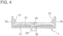
- Locking protrusions 77 are respectively formed on inner surfaces facing each other, of the side walls 73, as illustrated in FIG. 4 that is a cross-sectional view taken along line IV-IV of FIG. 3 .
- each side wall 73 restricts movement of the bus bar 51 toward a top of the side wall 73 beyond a tip end of the positioning pin 75, the bus bar 51 having climbed over the locking protrusion 77 from the top of the side wall 73 and moved toward the support plate 71. This restriction prevents the positioning pin 75 from coming out of the guide hole 55 and the bus bar 51 from being freely movable in the longitudinal direction with respect to the holding portion 7.
- the support plate 71 holds the bus bar 51 to be movable within a predetermined range determined by restriction of movement (movement in an extending direction of the positioning pin 75) of the bus bar 51 by an interference with the locking protrusion 77.
- each side wall 73 is formed at a position allowing a gap to be provided between the locking protrusion 77 and the bus bar 51 on the support plate 71, the gap allowing inclination of the bus bar 51 with respect to the support plate 71. Therefore, the bus bar 51 on the support plate 71 can take a posture inclined with respect to the support plate 71 in the gap between the bus bar 51 and the locking protrusion 77.
- the coupling portion 9 includes a pair of abutting portions 91 and 91 respectively abutting on the bus bars 51 and 51 held by the two adjacent holding portions 7 and 7, a pair of connecting walls 93 and 93 connecting the abutting portions 91 and 91, and coupling pieces 95 and 95 connecting the coupling portion 9 to the holding portions 7.
- Each abutting portion 91 abuts on a portion between the contact portion 53 and the guide hole 55 in the longitudinal direction of the two adjacent bus bars 51.
- Each connecting wall 93 connects side portions of the abutting portions 91 respectively abutting on the two adjacent bus bars 51 in a short side direction of the bus bars 51.
- the connecting walls 93 extend outside long sides of the bus bars 51 on which the abutting portions 91 abut, and are arranged between the side walls 73 of the two adjacent holding portions 7.
- Each coupling piece 95 connects each abutting portion 91 and the support plate 71 of the holding portion 7 adjacent to the coupling portion 9.
- Each coupling piece 95 is formed to be thinner than the abutting portion 91 and the support plate 71, and is configured to be deformable so that a relative angle (an elevation angle or a depression angle) between the abutting portion 91 and the support plate 71 becomes variable.
- the two adjacent holding portions 7 and 7 are coupled in a chain manner by the coupling portion 9 arranged between the holding portions 7 in a state where the relative angle (the elevation angle or the depression angle) with an adjacent holding portion 7 can be changed by deformation of the coupling pieces 95 and 95 on both sides of the abutting portions 91.
- the coupling portion 9 is formed in a rectangular frame shape by the pair of abutting portions 91 and 91 and the pair of connecting walls 93 and 93. Therefore, the coupling portion 9 has a rectangular opening 97 inside the pair of abutting portions 91 and 91 and the pair of connecting walls 93 and 93. Inside the opening 97, portions on the side of the contact portions 53 of the bus bars 51 abutting on the abutting portions 91 are arranged.
- the bus bar 51 is brought to be fit between the pair of side walls 73 of each holding portion 7 of the bus bar holder 6, thereby to be held by the holding portion 7.
- the bus bar 51 is supported by the support plate 71 by causing the bus bar 51 to climb over the locking protrusions 77 of the side walls 73 while inserting the positioning pin 75 of the support plate 71 into the guide hole 55 of the bus bar 51.
- the bus bar holder 6 having the holding portions 7 hold the bus bars 51 is placed on the electrodes 35 on the one end side and the electrodes 35 on the other end sides in the longitudinal direction on the top surfaces of the battery cells 33. Then, the bus bars 51 of the holding portions 7 moves toward the top surfaces of the battery cells 33 by its own weight.
- the coupling pieces 95 of the coupling portion 9 are deformed in accordance with the variation in height of the electrodes 35 of the battery cells 33. Then, the relative angle (the elevation angle or the depression angle) of the two adjacent holding portions 7 connected by the coupling portion 9 is adjusted.
- bus bar 51 held by each holding portion 7 moves in the direction along the support plate 71 within the range of the gap between the guide hole 55 and the positioning pin 75, and further moves in the direction along the positioning pin 75 between the support plate 71 and the locking protrusion 77 to the position of the posture where the corresponding contact portions 53 come in to contact with the electrodes 35 of the two adjacent battery cells 33.
- the contact portions 53 and 53 of two adjacent bus bars 51 and 51 arranged inside the opening 97 of the coupling portion 9 are respectively brought into contact with and adhere to the electrodes 35 and 35 of the two adjacent battery cells 33 and 33.
- the bus bar 51 on the holding portion 7 of the bus bar holder 6 placed on the electrodes 35 of the battery cells 33 is simply pressed against the top surfaces of the battery cells 33.
- the electrodes 35 and 35 of the two adjacent battery cells 33 and 33 are in an electrically connected state with an appropriate low contact resistance by the bus bar 51 having the contact portions 53 and 53 adhering to the electrodes 35, as illustrated in FIG. 5 that is the cross-sectional view taken along line V-V of FIG. 3 .
- the locking protrusion 77 of each side wall 73 is formed at a position allowing the gap provided between the locking protrusion 77 and the bus bar 51 on the support plate 71, the gap allowing inclination of the bus bar 51 with respect to the support plate 71. Therefore, the bus bar 51 on the support plate 71 can take a posture inclined with respect to the support plate 71 in the gap between the bus bar 51 and the locking protrusion 77.
- the contact portion 53 of the bus bar 51 adhering to the electrode 35 can be fixed to the electrode 35 in a firmly stacked state by welding the contact portion 53 to the electrode 35 or by applying a pressing force to each bus bar 51 toward the electrode 35 using fastening parts such as bolts (not illustrated).
- the bus bar holder 6 in which the plurality of holding portion 7 each holding the bus bar 51 is coupled in a chain manner by the thin coupling portions 9 is brought close to the electrodes 35 of the battery cells 33 to cause the coupling pieces 95 of the coupling portions 9 to be deformed in accordance with the variation in height of the electrodes 35 of the battery cells 33.
- bus bar 51 held by each holding portion 7 is brought to move in the direction along the support plate 71 within the range of the gap between the guide hole 55 and the positioning pin 75, and is further brought to move in the direction along the positioning pin 75 between the support plate 71 and the locking protrusion 77 to the position of the posture where the contact portions 53 come into contact with the electrodes 35 of the two adjacent battery cells 33.
- the contact portions 53 of the bus bars 51 arranged inside the openings 97 of the two adjacent coupling portions 9 are respectively brought into contact with and adhere to the electrodes 35 and 35 of the two adjacent battery cells 33 and 33. That is, the coupling portions of the bus bar holder are deformed, and the bus bar moves inside the holding portion within the predetermined ranges determined by restriction of movement of the bus bar in the holding portion by interferences with the movement restricting members, whereby each bus bar is set to the posture at which the contact portions are in contact with the electrodes of the two adjacent battery cells connected by the bus bar in each holding portion.
- the contact portions 53 of the bus bars 51 can be collectively arranged at positions in contact with the corresponding electrodes 35 of the battery cells 33 all at once by bringing the bus bar holder 6 close to the electrodes 35 of the battery cells 33 of the battery module 3.
- the contact portions of the bus bars held by the holding portions of the bus bar holder are collectively assembled to the positions in contact with the corresponding electrodes of the battery cells all at once.
- the gap allowing the bus bar 51 to take an inclined posture with respect to the support plate 71 is formed between the locking protrusion 77 and the bus bar 51 on the support plate 71. Therefore, the degree of freedom of the posture of the bus bar 51 in the holding portion 7 is increased, and the adhesiveness of the bus bar 51 to the electrodes 35 and 35 of the two battery cells 33 and 33 having variation in height can be further enhanced.
- the bus bar can take an inclined posture with respect to the support plate in the gap between the bus bar on the support plate and the movement restricting member, thereby to increase the degree of freedom of the posture of the bus bar in the holding portion, and enhance the adhesiveness of the bus bar to the electrodes of the battery cells having variation in positions.
- FIG. 7 is a perspective view of the bus bar module 5 according to the second embodiment of the present invention used for a battery pack 1 in FIG. 1 .
- each of a pair of side walls 73 and 73 of each holding portion 7 has a dimension larger than a long side of a bus bar 51 in a longitudinal direction of the bus bar 51 supported by a support plate 71. Then, an opening 79 is formed inside both the side walls 73 and the support plate 71 of each holding portion 7. Portions (including contact portions 53) of the bus bar 51 on end portion sides in the longitudinal direction, excluding a portion supported by the support plate 71, are arranged inside the opening 79.
- each coupling portion 9 coupling the holding portions 7 in a chain manner is constituted by only flexible curved pieces 98 connecting the side walls 73 of two adjacent holding portions 7.
- This curved piece 98 is constituted such that the two adjacent holding portions 7 can be deformed into a direction to change a relative angle (an elevation angle or a depression angle) of the two holding portions 7.
- the bus bar holder 6 of the bus bar module 5 of the present embodiment is different in configuration from the bus bar holder 6 of the bus bar module 5 of the first embodiment.
- the bus bar holder 6 having the holding portions 7 hold the bus bars 51 is placed on electrodes 35 on one end side and on electrodes 35 on the other end side in the longitudinal direction on top surfaces of battery cells 33, similarly to the bus bar module 5 of the first embodiment.
- the contact portions 53 of the bus bars 51 are brought into contact with the corresponding electrodes 35 of the battery cells 33 by its own weight of the bus bars 51 and the holding portions 7 or by pressing the bus bars 51 of the holding portions 7 against the top surfaces of the battery cells 33.
- FIG. 8 is the cross-sectional view taken along line VIII-VIII of FIG. 7 .
- the bus bar holder 6 in which the plurality of holding portion 7 each holding the bus bar 51 is coupled in a chain manner by the coupling portions 9, that is, by the thin curved pieces 98, is brought close to the electrodes 35 of the battery cells 33 to cause the curved pieces 98 of the coupling portions 9 to be deformed in accordance with the variation in height of the electrodes 35 of the battery cells 33.
- the locking protrusion 77 of each side wall 73 is formed at a position allowing the gap provided between the locking protrusion 77 and the bus bar 51 on the support plate 71, the gap allowing inclination of the bus bar 51 with respect to the support plate 71. Therefore, the bus bar 51 on the support plate 71 can take a posture inclined with respect to the support plate 71 in the gap between the bus bar 51 and the locking protrusion 77.
- bus bar 51 held by each holding portion 7 is brought to move in the direction along the support plate 71 within the range of the gap between the guide hole 55 and the positioning pin 75, and is further brought to move in the direction along the positioning pin 75 between the support plate 71 and the locking protrusion 77 to the position of the posture where the contact portions 53 come into contact with the electrodes 35 of the two adjacent battery cells 33.
- the contact portions 53 of the bus bar 51 arranged inside the opening 79 located on both sides of the support plate 71 in the longitudinal direction of the bus bar 51 supported by the support plate 71 are respectively brought into contact with and adhere to the electrodes 35 of the two adjacent battery cells 33.
- the bus bar becomes movable in an extending direction of the support plate with respect to the holding portion within a range of a gap between a positioning pin and a guide hole of the bus bar on the support plate, thereby to increase the degree of freedom of the posture of the bus bar in the holding portion, and enhance the adhesiveness of the bus bar to the electrodes of the battery cells having variation in positions.
- bus bar module 5 of the present embodiment thus configured, an effect similar to the effect of the bus bar module 5 of the first embodiment can be obtained.
- the opening through which the contact portion 53 of the bus bar 51 is exposed to the electrode 35 of the battery cell 33 as in the bus bar holder 6 of each embodiment may be provided in either of the holding portion 7 and the coupling portion 9.
- the configuration to restrict the moving range of the bus bar 51 with respect to the holding portion 7, that is, the movement restricting member is not limited to the combination of the positioning pin 75 of the support plate 71 of the holding portion 7 and the locking protrusions 77 of the side walls 73, as in the bus bar holder 6 of each embodiment, and may be either of the positioning pin 75 and the locking protrusions 77.
- an arbitrary configuration can be used as the movement restricting member in place of the positioning pin 75 and the locking protrusions 77.
- a battery pack of the present embodiment may include a battery module constituted by a large number of battery cells and the bus bar module as described above. With the configuration, the battery pack can exhibit the effect obtained by the bus bar module.
- the present invention is extremely useful when used for a battery pack in which terminals of a plurality of battery cells are connected by a bus bar module.
Landscapes
- Chemical & Material Sciences (AREA)
- Chemical Kinetics & Catalysis (AREA)
- Electrochemistry (AREA)
- General Chemical & Material Sciences (AREA)
- Connection Of Batteries Or Terminals (AREA)
- Battery Mounting, Suspending (AREA)
Abstract
Description
- The present invention relates to a battery pack in which terminals of a plurality of battery cells are connected by a bus bar module.
- For example, a battery mounted in an electric vehicle such as an electric vehicle (EV) or a hybrid vehicle (HEV) has a larger capacity than a battery mounted on an ordinary vehicle having an internal combustion engine as a propulsion source.
- In a battery of this type, the large capacity is realized by using a battery pack in which electrodes of a large number of battery cells constituting a battery module are connected by a bus bar. Since a large current flows through this bus bar, the bus bar needs to have a certain thickness.
- In addition, to suppress a contact resistance, the bus bar needs to sufficiently adhere to the electrodes of the battery cells of the battery module. However, the positions of the electrodes of the battery cells may vary due to dimensional errors within a tolerance of the battery cells. Therefore, the bus bar needs to apply a load toward the electrodes so as to adhere to any of the electrodes.
- Therefore, when a long bus bar connecting electrodes of many battery cells is used, dimensional errors of the battery cells overlap and variation in the positions of the electrodes to which the bus bar adheres become large, and the load applied to the bus bar may needs to be made large. In that case, a larger load is applied to the electrode close to the bus bar than the electrode distant from the bus bar, which may cause damage to the battery cell.
- According to
JP 2016-129125 A - Therefore, it is not necessary to apply a load to the bus bar like the long bus bar to adhere to the electrodes of many battery cells. In addition, since the posture of the bus bar can be changed according to the positions of the electrodes of the two adjacent battery cells, the bus bar can be easily brought to adhere to the electrodes.
- However, in the bus bar according to
JP 2016-129125 A - The present invention has been made to solve the above problems, and an object of the present invention is to provide a bus bar module capable of securing adhesiveness of a bus bar to electrodes of battery cells having variation in positions without impairing assemblability of the bus bar to electrodes of many battery cells constituting a battery module and, and a suitable battery pack using the bus bar module.
- A bus bar module according to the present invention includes
a plurality of bus bars each connecting electrodes of two adjacent battery cells of a large number of battery cells constituting a battery module, and
a bus bar holder constituted by coupling a plurality of holding portions in a chain manner via deformable coupling portions, respectively, the plurality of holding portions each holding the bus bar in a movable manner within a predetermined range determined by restriction of movement of the bus bar by an interference with a movement restricting member, and having openings provided in either the holding portion or the coupling portion, the openings allowing two contact portions of the bus bar held by the holding portion to be exposed to an outside, the two contact portions being respectively connected to the electrodes of the two adjacent battery cells. - In the bus bar module according to the present invention, the holding portion may include a support plate that supports a portion of the bus bar except the contact portions, and a pair of side walls erecting from the support plate, extending on both sides of the bus bar, and facing each other, and the movement restricting member may include a pair of protrusions projecting from facing surfaces of the side walls, respectively, and the bus bar that has climbed over the pair of protrusions, has moved toward the support plate, and has been held by the holding portion, may be movably held in an interval direction of the support plate and the protrusions between the support plate and the pair of protrusions.
- Further, in the bus bar module according to the present invention, the coupling portion may be connected to the support plate, and the support plate and the coupling portion may be arranged in a place facing a portion between the two contact portions of the bus bar held by the holding portion.
- Further, in the bus bar module according to the present invention, the movement restricting member may be arranged at a position allowing a gap to be provided between the movement restricting member and the bus bar on the support plate, the gap allowing inclination of the bus bar with respect to the support plate.
- Further, in the bus bar module according to the present invention, the holding portion may include a support plate that supports a portion of the bus bar except the contact portions, the movement restricting member may include a positioning pin projecting from the support plate and loosely inserted in a guide hole in the bus bar on the support plate, and the bus bar may be movably held along the support plate until the guide hole abuts against the positioning pin.
- Further, a battery pack of the present invention may include a battery module constituted by a large number of battery cells, and the bus bar module as described above.
- According to the present invention, adhesiveness of a bus bar to electrodes of battery cells having variation in positions can be secured without impairing assemblability of the bus bar to electrodes of many battery cells constituting a battery module.
-
-
FIG. 1 is a perspective view illustrating a schematic configuration of a battery pack according to an embodiment of the present invention; -
FIG. 2 is an explanatory view illustrating a connection state between electrodes by a short bus bar used for connection between electrodes of adjacent battery cells in a case where variation in electrode positions due to a dimensional tolerance of the battery cells inFIG 1 is absorbed by the bus bar; -
FIG. 3 is a perspective view of a bus bar module according to a first embodiment of the present invention used for a battery pack inFIG. 1 ; -
FIG. 4 is a cross-sectional view taken along line IV-IV of the bus bar module inFIG. 3 ; -
FIG. 5 is a cross-sectional view taken along line V-V of the bus bar module inFIG. 3 ; -
FIG. 6 is an enlarged explanatory view illustrating a posture in a holding portion of a bus bar holder of a bus bar connecting electrodes of two adjacent battery cells inFIG. 5 ; -
FIG. 7 is a perspective view of a bus bar module according to a second embodiment of the present invention used for a battery pack inFIG. 1 ; -
FIG. 8 is a cross-sectional view taken along line VIII-VIII of the bus bar module inFIG. 7 ; and -
FIG. 9 is an enlarged explanatory view illustrating a posture in a holding portion of a bus bar holder of a bus bar connecting electrodes of two adjacent battery cells inFIG. 8 . - Hereinafter, embodiments of the present invention will be described with reference to the drawings.
FIG. 1 is a perspective view illustrating a schematic configuration of a battery pack according to an embodiment of the present invention. A battery pack 1 illustrated inFIG. 1 includes abattery module 3 and abus bar module 5. - The
battery module 3 is constituted by a large number ofbattery cells 33. Each of thebattery cells 33 includes a pair ofelectrodes battery cells 33 are arranged such that long sides of the top surfaces are in contact with one another. -
FIG. 1 illustrates a case in which fourbattery cells 33 connected in parallel constitute oneunit cell 31, and a plurality of theunit cells 31 is connected in series to constitute the large-capacity battery module 3. Thebus bar module 5 illustrated inFIG. 1 is used for connection between theelectrodes 35 on one end side in the longitudinal direction of the top surfaces of thebattery cells 33 and for connection between theelectrodes 35 on the other end side. - Each of the
battery cells 33 of thebattery module 3 illustrated inFIG. 1 may include a dimensional error within a tolerance. If eachbattery cell 33 has the dimensional error, for example, as illustrated in the explanatory view inFIG. 2 , the position of theelectrode 35 in a height direction of eachbattery cell 33 varies. - Therefore, when connecting the electrodes of the plurality of
battery cells 33 by one bus bar, the bus bar cannot sufficiently adhere to theelectrode 35 of thebattery cell 33 lower in height than theother battery cells 33 to suppress a contact resistance. - Therefore, the
electrodes adjacent battery cells individual bus bar 51. Specifically,hemispherical contact portions 53 respectively projecting near both ends in a longitudinal direction of a back surface of therectangular bus bar 51 are respectively brought into contact with theelectrodes adjacent battery cells electrodes 35 by thebus bar 51. - By using the
individual bus bar 51 for connection of theelectrodes adjacent battery cells contact portions 53 of eachbus bar 51 can be brought to sufficiently adhere to theelectrodes 35 of the plurality ofbattery cells 33 having variation in height. - However, if using the
individual bus bar 51 for connection of theelectrodes adjacent battery cells bus bar 51 needs to be arranged between theelectrodes adjacent battery cells bus bar 51 requires much labor and cost as compared with a case of connecting electrodes of a plurality ofbattery cells 33 by one bus bar. - Therefore, in the present invention, the plurality of
bus bars 51 each connecting theelectrodes adjacent battery cells bus bar module 5. With the configuration, thebus bars 51 can be collectively arranged between theelectrodes bus bar module 5 will be described. - First, the
bus bar module 5 according to a first embodiment of the present invention will be described.FIG. 3 is a perspective view of thebus bar module 5 according to the first embodiment of the present invention used for the battery pack 1 inFIG. 1 . - As described above, the
bus bar module 5 of the present embodiment is used for connection between theelectrodes 35 on one end side in the longitudinal direction of the top surfaces of thebattery cells 33 and for connection between theelectrodes 35 on the other end side. Eachbus bar module 5 has abus bar holder 6 that holds a plurality of thebus bars 51. Aguide hole 55 not illustrated inFIGS. 1 and2 penetrates through the center of thebus bar 51. - The
bus bar holder 6 is formed of an insulating material such as a synthetic resin. Thebus bar holder 6 includes a plurality of holdingportions 7 each holding each of the plurality ofbus bars 51 and a plurality ofcoupling portions 9 coupling the holdingportions 7 in a chain manner. - The holding
portion 7 has asupport plate 71 supporting thebus bar 51 and a pair ofside walls 73 erected from thesupport plate 71. - The
support plate 71 supports a central portion in the longitudinal direction of thebus bar 51. The portion of thebus bar 51, the portion being supported by thesupport plate 71, does not include thecontact portions 53 of thebus bar 51 but includes a peripheral edge portion of theguide hole 55. A positioning pin 75 (movement restricting member) erects on thesupport plate 71. Thepositioning pin 75 is loosely inserted into theguide hole 55 of thebus bar 51 supported by thesupport plate 71. - Since the
positioning pin 75 is loosely inserted in theguide hole 55 of thebus bar 51, movement of thebus bar 51 in a direction along thesupport plate 71 is restricted within a predetermined range. Specifically, thebus bar 51 having thepositioning pin 75 loosely inserted in theguide hole 55 can move in the direction along thesupport plate 71 by an amount corresponding to a gap formed between theguide hole 55 and thepositioning pin 75. That is, thebus bar 51 having thepositioning pin 75 loosely inserted in theguide hole 55 can move in the direction along thesupport plate 71 within a range where thepositioning pin 75 remains inside theguide hole 55. - In other words, the
support plate 71 holds thebus bar 51 to be movable within a predetermined range determined by restriction of movement (movement in a direction in which thepositioning pin 75 is away from the center of the guide hole 55) of thebus bar 51 by an interference with thepositioning pin 75. - The
side walls 73 respectively extend outside both long sides of thebus bar 51 supported by thesupport plate 71. Locking protrusions 77 (protrusions and the movement restricting member) are respectively formed on inner surfaces facing each other, of theside walls 73, as illustrated inFIG. 4 that is a cross-sectional view taken along line IV-IV ofFIG. 3 . - The locking
protrusion 77 of eachside wall 73 restricts movement of thebus bar 51 toward a top of theside wall 73 beyond a tip end of thepositioning pin 75, thebus bar 51 having climbed over the lockingprotrusion 77 from the top of theside wall 73 and moved toward thesupport plate 71. This restriction prevents thepositioning pin 75 from coming out of theguide hole 55 and thebus bar 51 from being freely movable in the longitudinal direction with respect to the holdingportion 7. - In other words, the
support plate 71 holds thebus bar 51 to be movable within a predetermined range determined by restriction of movement (movement in an extending direction of the positioning pin 75) of thebus bar 51 by an interference with the lockingprotrusion 77. - Further, the locking
protrusion 77 of eachside wall 73 is formed at a position allowing a gap to be provided between the lockingprotrusion 77 and thebus bar 51 on thesupport plate 71, the gap allowing inclination of thebus bar 51 with respect to thesupport plate 71. Therefore, thebus bar 51 on thesupport plate 71 can take a posture inclined with respect to thesupport plate 71 in the gap between thebus bar 51 and the lockingprotrusion 77. - As illustrated in
FIG. 3 , thecoupling portion 9 includes a pair of abuttingportions adjacent holding portions walls portions coupling pieces coupling portion 9 to the holdingportions 7. - Each abutting
portion 91 abuts on a portion between thecontact portion 53 and theguide hole 55 in the longitudinal direction of the two adjacent bus bars 51. - Each connecting
wall 93 connects side portions of the abuttingportions 91 respectively abutting on the two adjacent bus bars 51 in a short side direction of the bus bars 51. The connectingwalls 93 extend outside long sides of the bus bars 51 on which the abuttingportions 91 abut, and are arranged between theside walls 73 of the twoadjacent holding portions 7. - Each
coupling piece 95 connects each abuttingportion 91 and thesupport plate 71 of the holdingportion 7 adjacent to thecoupling portion 9. Eachcoupling piece 95 is formed to be thinner than the abuttingportion 91 and thesupport plate 71, and is configured to be deformable so that a relative angle (an elevation angle or a depression angle) between the abuttingportion 91 and thesupport plate 71 becomes variable. - In other words, the two
adjacent holding portions coupling portion 9 arranged between the holdingportions 7 in a state where the relative angle (the elevation angle or the depression angle) with anadjacent holding portion 7 can be changed by deformation of thecoupling pieces portions 91. - Then, the
coupling portion 9 is formed in a rectangular frame shape by the pair of abuttingportions walls coupling portion 9 has arectangular opening 97 inside the pair of abuttingportions walls opening 97, portions on the side of thecontact portions 53 of the bus bars 51 abutting on the abuttingportions 91 are arranged. - Next, assembling work in the case of electrically connecting the
electrodes 35 of thebattery cells 33 of thebattery module 3 by thebus bar module 5 of the present embodiment configured as described above will be described. - First, the
bus bar 51 is brought to be fit between the pair ofside walls 73 of each holdingportion 7 of thebus bar holder 6, thereby to be held by the holdingportion 7. At this time, thebus bar 51 is supported by thesupport plate 71 by causing thebus bar 51 to climb over the lockingprotrusions 77 of theside walls 73 while inserting thepositioning pin 75 of thesupport plate 71 into theguide hole 55 of thebus bar 51. - Next, the
bus bar holder 6 having the holdingportions 7 hold the bus bars 51 is placed on theelectrodes 35 on the one end side and theelectrodes 35 on the other end sides in the longitudinal direction on the top surfaces of thebattery cells 33. Then, the bus bars 51 of the holdingportions 7 moves toward the top surfaces of thebattery cells 33 by its own weight. - When the bus bars 51 and the holding
portions 7 move toward thebattery cells 33, thecoupling pieces 95 of thecoupling portion 9 are deformed in accordance with the variation in height of theelectrodes 35 of thebattery cells 33. Then, the relative angle (the elevation angle or the depression angle) of the twoadjacent holding portions 7 connected by thecoupling portion 9 is adjusted. - Further, the
bus bar 51 held by each holdingportion 7 moves in the direction along thesupport plate 71 within the range of the gap between theguide hole 55 and thepositioning pin 75, and further moves in the direction along thepositioning pin 75 between thesupport plate 71 and the lockingprotrusion 77 to the position of the posture where thecorresponding contact portions 53 come in to contact with theelectrodes 35 of the twoadjacent battery cells 33. - Then, the
contact portions opening 97 of thecoupling portion 9 are respectively brought into contact with and adhere to theelectrodes adjacent battery cells - In a case where the
bus bar 51 and holdingportion 7 do not move toward thebattery cells 33, thebus bar 51 on the holdingportion 7 of thebus bar holder 6 placed on theelectrodes 35 of thebattery cells 33 is simply pressed against the top surfaces of thebattery cells 33. - As a result, the
electrodes adjacent battery cells bus bar 51 having thecontact portions electrodes 35, as illustrated inFIG. 5 that is the cross-sectional view taken along line V-V ofFIG. 3 . - Then, as illustrated in the explanatory view in
FIG. 6 illustrating an enlarged state of theelectrodes adjacent battery cells bus bar 51 inFIG. 5 , the lockingprotrusion 77 of eachside wall 73 is formed at a position allowing the gap provided between the lockingprotrusion 77 and thebus bar 51 on thesupport plate 71, the gap allowing inclination of thebus bar 51 with respect to thesupport plate 71. Therefore, thebus bar 51 on thesupport plate 71 can take a posture inclined with respect to thesupport plate 71 in the gap between thebus bar 51 and the lockingprotrusion 77. - Note that the
contact portion 53 of thebus bar 51 adhering to theelectrode 35 can be fixed to theelectrode 35 in a firmly stacked state by welding thecontact portion 53 to theelectrode 35 or by applying a pressing force to eachbus bar 51 toward theelectrode 35 using fastening parts such as bolts (not illustrated). - As described above, in the
bus bar module 5 of the present embodiment, thebus bar holder 6 in which the plurality of holdingportion 7 each holding thebus bar 51 is coupled in a chain manner by thethin coupling portions 9 is brought close to theelectrodes 35 of thebattery cells 33 to cause thecoupling pieces 95 of thecoupling portions 9 to be deformed in accordance with the variation in height of theelectrodes 35 of thebattery cells 33. - Further, the
bus bar 51 held by each holdingportion 7 is brought to move in the direction along thesupport plate 71 within the range of the gap between theguide hole 55 and thepositioning pin 75, and is further brought to move in the direction along thepositioning pin 75 between thesupport plate 71 and the lockingprotrusion 77 to the position of the posture where thecontact portions 53 come into contact with theelectrodes 35 of the twoadjacent battery cells 33. - Therefore, the
contact portions 53 of the bus bars 51 arranged inside theopenings 97 of the twoadjacent coupling portions 9 are respectively brought into contact with and adhere to theelectrodes adjacent battery cells - Therefore, even when there is variation within the tolerance in height of the
electrodes 35 of thebattery cells 33, thecontact portions 53 of the bus bars 51 can be collectively arranged at positions in contact with the correspondingelectrodes 35 of thebattery cells 33 all at once by bringing thebus bar holder 6 close to theelectrodes 35 of thebattery cells 33 of thebattery module 3. In other words, even when there is variation in positions of the electrodes of the battery cells due to dimensional errors within the tolerance of many battery cells constituting the battery module, the contact portions of the bus bars held by the holding portions of the bus bar holder are collectively assembled to the positions in contact with the corresponding electrodes of the battery cells all at once. - As a result, adhesiveness of the bus bars 51 to the
electrodes 35 of thebattery cells 33 having variation in the positions can be secured without impairing the assemblability of the bus bars 51 to theelectrodes 35 of themany battery cells 33, even when theshort bus bar 51 connecting theelectrodes 35 of the twoadjacent battery cells 33 is used. - Further, the gap allowing the
bus bar 51 to take an inclined posture with respect to thesupport plate 71 is formed between the lockingprotrusion 77 and thebus bar 51 on thesupport plate 71. Therefore, the degree of freedom of the posture of thebus bar 51 in the holdingportion 7 is increased, and the adhesiveness of thebus bar 51 to theelectrodes battery cells - In other words, the bus bar can take an inclined posture with respect to the support plate in the gap between the bus bar on the support plate and the movement restricting member, thereby to increase the degree of freedom of the posture of the bus bar in the holding portion, and enhance the adhesiveness of the bus bar to the electrodes of the battery cells having variation in positions.
- Next, a
bus bar module 5 according to a second embodiment of the present invention will be described.FIG. 7 is a perspective view of thebus bar module 5 according to the second embodiment of the present invention used for a battery pack 1 inFIG. 1 . - In a
bus bar holder 6 of thebus bar module 5 of the present embodiment, each of a pair ofside walls portion 7 has a dimension larger than a long side of abus bar 51 in a longitudinal direction of thebus bar 51 supported by asupport plate 71. Then, anopening 79 is formed inside both theside walls 73 and thesupport plate 71 of each holdingportion 7. Portions (including contact portions 53) of thebus bar 51 on end portion sides in the longitudinal direction, excluding a portion supported by thesupport plate 71, are arranged inside theopening 79. - Further, in the
bus bar holder 6 of the present embodiment, eachcoupling portion 9 coupling the holdingportions 7 in a chain manner is constituted by only flexiblecurved pieces 98 connecting theside walls 73 of twoadjacent holding portions 7. Thiscurved piece 98 is constituted such that the twoadjacent holding portions 7 can be deformed into a direction to change a relative angle (an elevation angle or a depression angle) of the two holdingportions 7. - In these respects, the
bus bar holder 6 of thebus bar module 5 of the present embodiment is different in configuration from thebus bar holder 6 of thebus bar module 5 of the first embodiment. - In the
bus bar module 5 of the present embodiment constituted as described above, thebus bar holder 6 having the holdingportions 7 hold the bus bars 51 is placed onelectrodes 35 on one end side and onelectrodes 35 on the other end side in the longitudinal direction on top surfaces ofbattery cells 33, similarly to thebus bar module 5 of the first embodiment. - Then, the
contact portions 53 of the bus bars 51 are brought into contact with the correspondingelectrodes 35 of thebattery cells 33 by its own weight of the bus bars 51 and the holdingportions 7 or by pressing the bus bars 51 of the holdingportions 7 against the top surfaces of thebattery cells 33. - As a result, the
electrodes adjacent battery cells bus bar 51 having thecontact portions electrodes 35, as illustrated inFIG. 8 that is the cross-sectional view taken along line VIII-VIII ofFIG. 7 . - As described above, in the
bus bar module 5 of the present embodiment, thebus bar holder 6 in which the plurality of holdingportion 7 each holding thebus bar 51 is coupled in a chain manner by thecoupling portions 9, that is, by the thincurved pieces 98, is brought close to theelectrodes 35 of thebattery cells 33 to cause thecurved pieces 98 of thecoupling portions 9 to be deformed in accordance with the variation in height of theelectrodes 35 of thebattery cells 33. - Then, as illustrated in the explanatory view in
FIG. 9 illustrating an enlarged state of theelectrodes adjacent battery cells bus bar 51 inFIG. 8 , the lockingprotrusion 77 of eachside wall 73 is formed at a position allowing the gap provided between the lockingprotrusion 77 and thebus bar 51 on thesupport plate 71, the gap allowing inclination of thebus bar 51 with respect to thesupport plate 71. Therefore, thebus bar 51 on thesupport plate 71 can take a posture inclined with respect to thesupport plate 71 in the gap between thebus bar 51 and the lockingprotrusion 77. - Further, the
bus bar 51 held by each holdingportion 7 is brought to move in the direction along thesupport plate 71 within the range of the gap between theguide hole 55 and thepositioning pin 75, and is further brought to move in the direction along thepositioning pin 75 between thesupport plate 71 and the lockingprotrusion 77 to the position of the posture where thecontact portions 53 come into contact with theelectrodes 35 of the twoadjacent battery cells 33. - Therefore, the
contact portions 53 of thebus bar 51 arranged inside theopening 79 located on both sides of thesupport plate 71 in the longitudinal direction of thebus bar 51 supported by thesupport plate 71 are respectively brought into contact with and adhere to theelectrodes 35 of the twoadjacent battery cells 33. - In other words, the bus bar becomes movable in an extending direction of the support plate with respect to the holding portion within a range of a gap between a positioning pin and a guide hole of the bus bar on the support plate, thereby to increase the degree of freedom of the posture of the bus bar in the holding portion, and enhance the adhesiveness of the bus bar to the electrodes of the battery cells having variation in positions.
- With the
bus bar module 5 of the present embodiment thus configured, an effect similar to the effect of thebus bar module 5 of the first embodiment can be obtained. - Note that the opening through which the
contact portion 53 of thebus bar 51 is exposed to theelectrode 35 of thebattery cell 33 as in thebus bar holder 6 of each embodiment may be provided in either of the holdingportion 7 and thecoupling portion 9. - Further, the configuration to restrict the moving range of the
bus bar 51 with respect to the holdingportion 7, that is, the movement restricting member is not limited to the combination of thepositioning pin 75 of thesupport plate 71 of the holdingportion 7 and the lockingprotrusions 77 of theside walls 73, as in thebus bar holder 6 of each embodiment, and may be either of thepositioning pin 75 and the lockingprotrusions 77. Alternatively, an arbitrary configuration can be used as the movement restricting member in place of thepositioning pin 75 and the lockingprotrusions 77. - Furthermore, a battery pack of the present embodiment may include a battery module constituted by a large number of battery cells and the bus bar module as described above. With the configuration, the battery pack can exhibit the effect obtained by the bus bar module.
- The present invention is extremely useful when used for a battery pack in which terminals of a plurality of battery cells are connected by a bus bar module.
-
- 1
- battery pack
- 3
- battery module
- 5
- bus bar module
- 6
- bus bar holder
- 7
- holding portion
- 9
- coupling portion
- 31
- unit cell
- 33
- battery cell
- 35
- electrode
- 51
- bus bar
- 53
- contact portion
- 55
- guide hole
- 71
- support plate (central portion of bottom of holding portion)
- 73
- side wall
- 75
- positioning pin (movement restricting member)
- 77
- locking protrusions (protrusion and the movement restricting member)
- 79, 97
- opening
- 91
- abutting portion
- 93
- connecting wall
- 95
- coupling piece
- 98
- curved piece
Claims (6)
- A bus bar module (5) comprising:a plurality of bus bars (51) each connecting electrodes (35) of two adjacent battery cells (33) of a plurality of battery cells (33) constituting a battery module (3); anda bus bar holder (6) constituted by coupling a plurality of holding portions (7) in a chain manner via deformable coupling portions (9), respectively, the plurality of holding portions (7) each holding the bus bar (51) in a movable manner within a predetermined range determined by restriction of movement of the bus bar (51) by an interference with a movement restricting member (75, 77), and having opening (79, 97) provided in either the holding portion (7) or the coupling portion (9), the opening (79, 97) allowing two contact portions (53) of the bus bar (51) held by the holding portion (7) to be exposed to an outside, the two contact portions (53) being respectively connected to the electrodes (35) of the two adjacent battery cells (33).
- The bus bar module (5) according to claim 1, wherein
the holding portion (7) includes a support plate (71) that supports a portion of the bus bar (51) except the contact portions (53), and a pair of side walls (73) erecting from the support plate (71), extending on both sides of the bus bar (51), and facing each other, and
the movement restricting member (77) includes a pair of protrusions (77) projecting from facing surfaces of the side walls (73), respectively, and the bus bar (51) that has climbed over the pair of protrusions (77), has moved toward the support plate (71), and has been held by the holding portion (7), is movably held in an interval direction of the support plate (71) and the protrusions (77) between the support plate (71) and the pair of protrusions (77). - The bus bar module (5) according to claim 2, wherein
the coupling portion (9) is connected to the support plate (71), and the support plate (71) and the coupling portion (9) are arranged in a place facing a portion between the two contact portions (53) of the bus bar (51) held by the holding portion (7). - The bus bar module (5) according to claim 2 or 3, wherein
the movement restricting member (75, 77) is arranged at a position allowing a gap to be provided between the movement restricting member (75, 77) and the bus bar (51) on the support plate (71), the gap allowing inclination of the bus bar (51) with respect to the support plate (71). - The bus bar module (5) according any one of claims 1 to 4, wherein
the holding portion (7) includes a support plate (71) that supports a portion of the bus bar (51) except the contact portions (53), the movement restricting member (75) includes a positioning pin (75) projecting from the support plate (71) and loosely inserted in a guide hole (55) in the bus bar (51) on the support plate (71), and the bus bar (51) is movably held along the support plate (71) until the guide hole (55) abuts against the positioning pin (75). - A battery pack comprising:a battery module (3) constituted by a plurality of battery cells (33); andthe bus bar module (5) according to any one of claims 1 to 5.
Applications Claiming Priority (1)
| Application Number | Priority Date | Filing Date | Title |
|---|---|---|---|
| JP2018046458A JP6709816B2 (en) | 2018-03-14 | 2018-03-14 | Busbar module and battery pack |
Publications (2)
| Publication Number | Publication Date |
|---|---|
| EP3540821A1 true EP3540821A1 (en) | 2019-09-18 |
| EP3540821B1 EP3540821B1 (en) | 2020-06-17 |
Family
ID=65766860
Family Applications (1)
| Application Number | Title | Priority Date | Filing Date |
|---|---|---|---|
| EP19162063.2A Active EP3540821B1 (en) | 2018-03-14 | 2019-03-12 | Bus bar module and battery pack |
Country Status (4)
| Country | Link |
|---|---|
| US (1) | US11031658B2 (en) |
| EP (1) | EP3540821B1 (en) |
| JP (1) | JP6709816B2 (en) |
| CN (1) | CN110277518B (en) |
Cited By (2)
| Publication number | Priority date | Publication date | Assignee | Title |
|---|---|---|---|---|
| WO2023056998A1 (en) * | 2021-10-08 | 2023-04-13 | Gentherm Gmbh | Connection device, battery module, and method for producing a battery module |
| CN116544591A (en) * | 2022-02-01 | 2023-08-04 | 丰田自动车株式会社 | Power storage module |
Families Citing this family (5)
| Publication number | Priority date | Publication date | Assignee | Title |
|---|---|---|---|---|
| KR102409422B1 (en) * | 2019-02-22 | 2022-06-15 | 주식회사 엘지에너지솔루션 | Bus bar for connecting battery cells, battery pack and method for manufacturing the same |
| CN118613960A (en) * | 2022-01-31 | 2024-09-06 | 松下知识产权经营株式会社 | Power storage module |
| CN220934334U (en) * | 2024-02-22 | 2024-05-10 | 宁德时代新能源科技股份有限公司 | Batteries, electrical equipment and energy storage equipment |
| JP2026000133A (en) * | 2024-06-17 | 2026-01-05 | プライムプラネットエナジー&ソリューションズ株式会社 | Batteries and battery packs |
| WO2026079269A1 (en) * | 2024-10-10 | 2026-04-16 | 株式会社Honda・GS Yuasa EV Battery R&D | Power storage device |
Citations (3)
| Publication number | Priority date | Publication date | Assignee | Title |
|---|---|---|---|---|
| US20110287299A1 (en) * | 2010-05-24 | 2011-11-24 | Kim Tae-Yong | Battery module |
| JP2015065055A (en) * | 2013-09-25 | 2015-04-09 | 株式会社デンソー | Battery module and assembling method thereof |
| JP2016129125A (en) | 2015-01-09 | 2016-07-14 | 株式会社Gsユアサ | Power storage device |
Family Cites Families (8)
| Publication number | Priority date | Publication date | Assignee | Title |
|---|---|---|---|---|
| KR101146677B1 (en) * | 2009-10-30 | 2012-05-22 | 에스비리모티브 주식회사 | Busbar holder |
| JP5644523B2 (en) * | 2010-12-07 | 2014-12-24 | 住友電装株式会社 | Battery connector |
| JP5787140B2 (en) * | 2011-06-13 | 2015-09-30 | 株式会社オートネットワーク技術研究所 | Battery wiring module |
| CN202839812U (en) * | 2012-08-28 | 2013-03-27 | 惠州比亚迪电池有限公司 | Integrated component of power connection and signal collection |
| JP6062266B2 (en) * | 2013-01-30 | 2017-01-18 | 矢崎総業株式会社 | Bus bar module and power supply |
| JP6326036B2 (en) * | 2015-12-18 | 2018-05-16 | 矢崎総業株式会社 | Busbar module and battery pack |
| JP2017195077A (en) * | 2016-04-20 | 2017-10-26 | 株式会社オートネットワーク技術研究所 | Connection module |
| JP6434468B2 (en) * | 2016-09-30 | 2018-12-05 | 株式会社オートネットワーク技術研究所 | Connection module |
-
2018
- 2018-03-14 JP JP2018046458A patent/JP6709816B2/en active Active
-
2019
- 2019-03-12 EP EP19162063.2A patent/EP3540821B1/en active Active
- 2019-03-13 US US16/351,663 patent/US11031658B2/en active Active
- 2019-03-14 CN CN201910192299.8A patent/CN110277518B/en active Active
Patent Citations (3)
| Publication number | Priority date | Publication date | Assignee | Title |
|---|---|---|---|---|
| US20110287299A1 (en) * | 2010-05-24 | 2011-11-24 | Kim Tae-Yong | Battery module |
| JP2015065055A (en) * | 2013-09-25 | 2015-04-09 | 株式会社デンソー | Battery module and assembling method thereof |
| JP2016129125A (en) | 2015-01-09 | 2016-07-14 | 株式会社Gsユアサ | Power storage device |
Cited By (2)
| Publication number | Priority date | Publication date | Assignee | Title |
|---|---|---|---|---|
| WO2023056998A1 (en) * | 2021-10-08 | 2023-04-13 | Gentherm Gmbh | Connection device, battery module, and method for producing a battery module |
| CN116544591A (en) * | 2022-02-01 | 2023-08-04 | 丰田自动车株式会社 | Power storage module |
Also Published As
| Publication number | Publication date |
|---|---|
| US20190288266A1 (en) | 2019-09-19 |
| JP2019160597A (en) | 2019-09-19 |
| EP3540821B1 (en) | 2020-06-17 |
| CN110277518B (en) | 2023-08-04 |
| US11031658B2 (en) | 2021-06-08 |
| CN110277518A (en) | 2019-09-24 |
| JP6709816B2 (en) | 2020-06-17 |
Similar Documents
| Publication | Publication Date | Title |
|---|---|---|
| EP3540821B1 (en) | Bus bar module and battery pack | |
| US7871723B2 (en) | Power source device | |
| KR102777895B1 (en) | Connecting assemblies, battery modules, battery packs and devices using battery modules as power sources | |
| JP7212504B2 (en) | connection module | |
| CN102576843B (en) | Cover member and power supply device equipped with this cover member | |
| EP2955738B1 (en) | Busbar for power storage device | |
| US8999546B2 (en) | Structure of prismatic battery modules with scalable architecture | |
| EP2390945B1 (en) | Battery module | |
| US10665887B2 (en) | Energy storage apparatus including aligning projection contacting energy storage devices | |
| US20150303415A1 (en) | Assembled battery and method for manufacturing assembled battery | |
| EP3800695B1 (en) | Battery box and battery module | |
| JP6986504B2 (en) | Connection module | |
| JP6145314B2 (en) | Bus bar module and power supply | |
| CN107112465A (en) | The manufacture method of battery module and battery module | |
| US20140248518A1 (en) | Power supply device | |
| JP2014049237A (en) | Housing section for bus bar module | |
| KR20220069058A (en) | Connection assemblies, battery modules, battery packs, and devices powered by battery modules | |
| CN112106221A (en) | Connection module and power storage module | |
| KR20230102738A (en) | Bus bar holder, bus bar assembly and battery module | |
| KR102944241B1 (en) | Battery pack | |
| US20140342620A1 (en) | Cell contacting arrangement for an energy storage device | |
| JP2012164437A (en) | Battery connection assembly | |
| CN103996817A (en) | Power supply device | |
| US12456783B2 (en) | Energy storage module | |
| CN115377616B (en) | Battery module |
Legal Events
| Date | Code | Title | Description |
|---|---|---|---|
| PUAI | Public reference made under article 153(3) epc to a published international application that has entered the european phase |
Free format text: ORIGINAL CODE: 0009012 |
|
| STAA | Information on the status of an ep patent application or granted ep patent |
Free format text: STATUS: REQUEST FOR EXAMINATION WAS MADE |
|
| 17P | Request for examination filed |
Effective date: 20190312 |
|
| AK | Designated contracting states |
Kind code of ref document: A1 Designated state(s): AL AT BE BG CH CY CZ DE DK EE ES FI FR GB GR HR HU IE IS IT LI LT LU LV MC MK MT NL NO PL PT RO RS SE SI SK SM TR |
|
| AX | Request for extension of the european patent |
Extension state: BA ME |
|
| RBV | Designated contracting states (corrected) |
Designated state(s): AL AT BE BG CH CY CZ DE DK EE ES FI FR GB GR HR HU IE IS IT LI LT LU LV MC MK MT NL NO PL PT RO RS SE SI SK SM TR |
|
| GRAJ | Information related to disapproval of communication of intention to grant by the applicant or resumption of examination proceedings by the epo deleted |
Free format text: ORIGINAL CODE: EPIDOSDIGR1 |
|
| STAA | Information on the status of an ep patent application or granted ep patent |
Free format text: STATUS: GRANT OF PATENT IS INTENDED |
|
| GRAP | Despatch of communication of intention to grant a patent |
Free format text: ORIGINAL CODE: EPIDOSNIGR1 |
|
| INTG | Intention to grant announced |
Effective date: 20200320 |
|
| GRAS | Grant fee paid |
Free format text: ORIGINAL CODE: EPIDOSNIGR3 |
|
| GRAA | (expected) grant |
Free format text: ORIGINAL CODE: 0009210 |
|
| STAA | Information on the status of an ep patent application or granted ep patent |
Free format text: STATUS: THE PATENT HAS BEEN GRANTED |
|
| AK | Designated contracting states |
Kind code of ref document: B1 Designated state(s): AL AT BE BG CH CY CZ DE DK EE ES FI FR GB GR HR HU IE IS IT LI LT LU LV MC MK MT NL NO PL PT RO RS SE SI SK SM TR |
|
| REG | Reference to a national code |
Ref country code: GB Ref legal event code: FG4D |
|
| REG | Reference to a national code |
Ref country code: CH Ref legal event code: EP |
|
| REG | Reference to a national code |
Ref country code: DE Ref legal event code: R096 Ref document number: 602019000184 Country of ref document: DE |
|
| REG | Reference to a national code |
Ref country code: IE Ref legal event code: FG4D |
|
| REG | Reference to a national code |
Ref country code: AT Ref legal event code: REF Ref document number: 1282426 Country of ref document: AT Kind code of ref document: T Effective date: 20200715 |
|
| PG25 | Lapsed in a contracting state [announced via postgrant information from national office to epo] |
Ref country code: GR Free format text: LAPSE BECAUSE OF FAILURE TO SUBMIT A TRANSLATION OF THE DESCRIPTION OR TO PAY THE FEE WITHIN THE PRESCRIBED TIME-LIMIT Effective date: 20200918 Ref country code: NO Free format text: LAPSE BECAUSE OF FAILURE TO SUBMIT A TRANSLATION OF THE DESCRIPTION OR TO PAY THE FEE WITHIN THE PRESCRIBED TIME-LIMIT Effective date: 20200917 Ref country code: SE Free format text: LAPSE BECAUSE OF FAILURE TO SUBMIT A TRANSLATION OF THE DESCRIPTION OR TO PAY THE FEE WITHIN THE PRESCRIBED TIME-LIMIT Effective date: 20200617 Ref country code: FI Free format text: LAPSE BECAUSE OF FAILURE TO SUBMIT A TRANSLATION OF THE DESCRIPTION OR TO PAY THE FEE WITHIN THE PRESCRIBED TIME-LIMIT Effective date: 20200617 Ref country code: LT Free format text: LAPSE BECAUSE OF FAILURE TO SUBMIT A TRANSLATION OF THE DESCRIPTION OR TO PAY THE FEE WITHIN THE PRESCRIBED TIME-LIMIT Effective date: 20200617 |
|
| REG | Reference to a national code |
Ref country code: LT Ref legal event code: MG4D |
|
| REG | Reference to a national code |
Ref country code: NL Ref legal event code: MP Effective date: 20200617 |
|
| REG | Reference to a national code |
Ref country code: DE Ref legal event code: R079 Ref document number: 602019000184 Country of ref document: DE Free format text: PREVIOUS MAIN CLASS: H01M0002200000 Ipc: H01M0050500000 |
|
| PG25 | Lapsed in a contracting state [announced via postgrant information from national office to epo] |
Ref country code: HR Free format text: LAPSE BECAUSE OF FAILURE TO SUBMIT A TRANSLATION OF THE DESCRIPTION OR TO PAY THE FEE WITHIN THE PRESCRIBED TIME-LIMIT Effective date: 20200617 Ref country code: BG Free format text: LAPSE BECAUSE OF FAILURE TO SUBMIT A TRANSLATION OF THE DESCRIPTION OR TO PAY THE FEE WITHIN THE PRESCRIBED TIME-LIMIT Effective date: 20200917 Ref country code: LV Free format text: LAPSE BECAUSE OF FAILURE TO SUBMIT A TRANSLATION OF THE DESCRIPTION OR TO PAY THE FEE WITHIN THE PRESCRIBED TIME-LIMIT Effective date: 20200617 Ref country code: RS Free format text: LAPSE BECAUSE OF FAILURE TO SUBMIT A TRANSLATION OF THE DESCRIPTION OR TO PAY THE FEE WITHIN THE PRESCRIBED TIME-LIMIT Effective date: 20200617 |
|
| REG | Reference to a national code |
Ref country code: AT Ref legal event code: MK05 Ref document number: 1282426 Country of ref document: AT Kind code of ref document: T Effective date: 20200617 |
|
| PG25 | Lapsed in a contracting state [announced via postgrant information from national office to epo] |
Ref country code: AL Free format text: LAPSE BECAUSE OF FAILURE TO SUBMIT A TRANSLATION OF THE DESCRIPTION OR TO PAY THE FEE WITHIN THE PRESCRIBED TIME-LIMIT Effective date: 20200617 Ref country code: NL Free format text: LAPSE BECAUSE OF FAILURE TO SUBMIT A TRANSLATION OF THE DESCRIPTION OR TO PAY THE FEE WITHIN THE PRESCRIBED TIME-LIMIT Effective date: 20200617 |
|
| PG25 | Lapsed in a contracting state [announced via postgrant information from national office to epo] |
Ref country code: PT Free format text: LAPSE BECAUSE OF FAILURE TO SUBMIT A TRANSLATION OF THE DESCRIPTION OR TO PAY THE FEE WITHIN THE PRESCRIBED TIME-LIMIT Effective date: 20201019 Ref country code: ES Free format text: LAPSE BECAUSE OF FAILURE TO SUBMIT A TRANSLATION OF THE DESCRIPTION OR TO PAY THE FEE WITHIN THE PRESCRIBED TIME-LIMIT Effective date: 20200617 Ref country code: AT Free format text: LAPSE BECAUSE OF FAILURE TO SUBMIT A TRANSLATION OF THE DESCRIPTION OR TO PAY THE FEE WITHIN THE PRESCRIBED TIME-LIMIT Effective date: 20200617 Ref country code: IT Free format text: LAPSE BECAUSE OF FAILURE TO SUBMIT A TRANSLATION OF THE DESCRIPTION OR TO PAY THE FEE WITHIN THE PRESCRIBED TIME-LIMIT Effective date: 20200617 Ref country code: EE Free format text: LAPSE BECAUSE OF FAILURE TO SUBMIT A TRANSLATION OF THE DESCRIPTION OR TO PAY THE FEE WITHIN THE PRESCRIBED TIME-LIMIT Effective date: 20200617 Ref country code: SM Free format text: LAPSE BECAUSE OF FAILURE TO SUBMIT A TRANSLATION OF THE DESCRIPTION OR TO PAY THE FEE WITHIN THE PRESCRIBED TIME-LIMIT Effective date: 20200617 Ref country code: RO Free format text: LAPSE BECAUSE OF FAILURE TO SUBMIT A TRANSLATION OF THE DESCRIPTION OR TO PAY THE FEE WITHIN THE PRESCRIBED TIME-LIMIT Effective date: 20200617 Ref country code: CZ Free format text: LAPSE BECAUSE OF FAILURE TO SUBMIT A TRANSLATION OF THE DESCRIPTION OR TO PAY THE FEE WITHIN THE PRESCRIBED TIME-LIMIT Effective date: 20200617 |
|
| PG25 | Lapsed in a contracting state [announced via postgrant information from national office to epo] |
Ref country code: SK Free format text: LAPSE BECAUSE OF FAILURE TO SUBMIT A TRANSLATION OF THE DESCRIPTION OR TO PAY THE FEE WITHIN THE PRESCRIBED TIME-LIMIT Effective date: 20200617 Ref country code: PL Free format text: LAPSE BECAUSE OF FAILURE TO SUBMIT A TRANSLATION OF THE DESCRIPTION OR TO PAY THE FEE WITHIN THE PRESCRIBED TIME-LIMIT Effective date: 20200617 Ref country code: IS Free format text: LAPSE BECAUSE OF FAILURE TO SUBMIT A TRANSLATION OF THE DESCRIPTION OR TO PAY THE FEE WITHIN THE PRESCRIBED TIME-LIMIT Effective date: 20201017 |
|
| REG | Reference to a national code |
Ref country code: DE Ref legal event code: R097 Ref document number: 602019000184 Country of ref document: DE |
|
| PLBE | No opposition filed within time limit |
Free format text: ORIGINAL CODE: 0009261 |
|
| STAA | Information on the status of an ep patent application or granted ep patent |
Free format text: STATUS: NO OPPOSITION FILED WITHIN TIME LIMIT |
|
| PG25 | Lapsed in a contracting state [announced via postgrant information from national office to epo] |
Ref country code: DK Free format text: LAPSE BECAUSE OF FAILURE TO SUBMIT A TRANSLATION OF THE DESCRIPTION OR TO PAY THE FEE WITHIN THE PRESCRIBED TIME-LIMIT Effective date: 20200617 |
|
| 26N | No opposition filed |
Effective date: 20210318 |
|
| PG25 | Lapsed in a contracting state [announced via postgrant information from national office to epo] |
Ref country code: MC Free format text: LAPSE BECAUSE OF FAILURE TO SUBMIT A TRANSLATION OF THE DESCRIPTION OR TO PAY THE FEE WITHIN THE PRESCRIBED TIME-LIMIT Effective date: 20200617 |
|
| REG | Reference to a national code |
Ref country code: BE Ref legal event code: MM Effective date: 20210331 |
|
| PG25 | Lapsed in a contracting state [announced via postgrant information from national office to epo] |
Ref country code: FR Free format text: LAPSE BECAUSE OF NON-PAYMENT OF DUE FEES Effective date: 20210331 Ref country code: LU Free format text: LAPSE BECAUSE OF NON-PAYMENT OF DUE FEES Effective date: 20210312 Ref country code: IE Free format text: LAPSE BECAUSE OF NON-PAYMENT OF DUE FEES Effective date: 20210312 |
|
| PG25 | Lapsed in a contracting state [announced via postgrant information from national office to epo] |
Ref country code: BE Free format text: LAPSE BECAUSE OF NON-PAYMENT OF DUE FEES Effective date: 20210331 |
|
| REG | Reference to a national code |
Ref country code: CH Ref legal event code: PL |
|
| PG25 | Lapsed in a contracting state [announced via postgrant information from national office to epo] |
Ref country code: LI Free format text: LAPSE BECAUSE OF NON-PAYMENT OF DUE FEES Effective date: 20220331 Ref country code: CH Free format text: LAPSE BECAUSE OF NON-PAYMENT OF DUE FEES Effective date: 20220331 |
|
| PG25 | Lapsed in a contracting state [announced via postgrant information from national office to epo] |
Ref country code: CY Free format text: LAPSE BECAUSE OF FAILURE TO SUBMIT A TRANSLATION OF THE DESCRIPTION OR TO PAY THE FEE WITHIN THE PRESCRIBED TIME-LIMIT Effective date: 20200617 |
|
| PG25 | Lapsed in a contracting state [announced via postgrant information from national office to epo] |
Ref country code: HU Free format text: LAPSE BECAUSE OF FAILURE TO SUBMIT A TRANSLATION OF THE DESCRIPTION OR TO PAY THE FEE WITHIN THE PRESCRIBED TIME-LIMIT; INVALID AB INITIO Effective date: 20190312 |
|
| PG25 | Lapsed in a contracting state [announced via postgrant information from national office to epo] |
Ref country code: SI Free format text: LAPSE BECAUSE OF FAILURE TO SUBMIT A TRANSLATION OF THE DESCRIPTION OR TO PAY THE FEE WITHIN THE PRESCRIBED TIME-LIMIT Effective date: 20200617 |
|
| GBPC | Gb: european patent ceased through non-payment of renewal fee |
Effective date: 20230312 |
|
| PG25 | Lapsed in a contracting state [announced via postgrant information from national office to epo] |
Ref country code: GB Free format text: LAPSE BECAUSE OF NON-PAYMENT OF DUE FEES Effective date: 20230312 |
|
| PG25 | Lapsed in a contracting state [announced via postgrant information from national office to epo] |
Ref country code: GB Free format text: LAPSE BECAUSE OF NON-PAYMENT OF DUE FEES Effective date: 20230312 |
|
| PG25 | Lapsed in a contracting state [announced via postgrant information from national office to epo] |
Ref country code: MK Free format text: LAPSE BECAUSE OF FAILURE TO SUBMIT A TRANSLATION OF THE DESCRIPTION OR TO PAY THE FEE WITHIN THE PRESCRIBED TIME-LIMIT Effective date: 20200617 |
|
| PG25 | Lapsed in a contracting state [announced via postgrant information from national office to epo] |
Ref country code: TR Free format text: LAPSE BECAUSE OF FAILURE TO SUBMIT A TRANSLATION OF THE DESCRIPTION OR TO PAY THE FEE WITHIN THE PRESCRIBED TIME-LIMIT Effective date: 20200617 |
|
| PG25 | Lapsed in a contracting state [announced via postgrant information from national office to epo] |
Ref country code: MT Free format text: LAPSE BECAUSE OF FAILURE TO SUBMIT A TRANSLATION OF THE DESCRIPTION OR TO PAY THE FEE WITHIN THE PRESCRIBED TIME-LIMIT Effective date: 20200617 |
|
| PGFP | Annual fee paid to national office [announced via postgrant information from national office to epo] |
Ref country code: DE Payment date: 20260128 Year of fee payment: 8 |