EP3540740A1 - Medical imaging apparatus, medical imaging apparatus control method, and computer program product - Google Patents
Medical imaging apparatus, medical imaging apparatus control method, and computer program product Download PDFInfo
- Publication number
- EP3540740A1 EP3540740A1 EP19161521.0A EP19161521A EP3540740A1 EP 3540740 A1 EP3540740 A1 EP 3540740A1 EP 19161521 A EP19161521 A EP 19161521A EP 3540740 A1 EP3540740 A1 EP 3540740A1
- Authority
- EP
- European Patent Office
- Prior art keywords
- value
- imaging apparatus
- parameter
- medical imaging
- input
- Prior art date
- Legal status (The legal status is an assumption and is not a legal conclusion. Google has not performed a legal analysis and makes no representation as to the accuracy of the status listed.)
- Granted
Links
Images




Classifications
-
- G—PHYSICS
- G16—INFORMATION AND COMMUNICATION TECHNOLOGY [ICT] SPECIALLY ADAPTED FOR SPECIFIC APPLICATION FIELDS
- G16H—HEALTHCARE INFORMATICS, i.e. INFORMATION AND COMMUNICATION TECHNOLOGY [ICT] SPECIALLY ADAPTED FOR THE HANDLING OR PROCESSING OF MEDICAL OR HEALTHCARE DATA
- G16H30/00—ICT specially adapted for the handling or processing of medical images
- G16H30/40—ICT specially adapted for the handling or processing of medical images for processing medical images, e.g. editing
-
- A—HUMAN NECESSITIES
- A61—MEDICAL OR VETERINARY SCIENCE; HYGIENE
- A61B—DIAGNOSIS; SURGERY; IDENTIFICATION
- A61B8/00—Diagnosis using ultrasonic, sonic or infrasonic waves
- A61B8/52—Devices using data or image processing specially adapted for diagnosis using ultrasonic, sonic or infrasonic waves
- A61B8/5292—Devices using data or image processing specially adapted for diagnosis using ultrasonic, sonic or infrasonic waves using additional data, e.g. patient information, image labeling, acquisition parameters
-
- A—HUMAN NECESSITIES
- A61—MEDICAL OR VETERINARY SCIENCE; HYGIENE
- A61B—DIAGNOSIS; SURGERY; IDENTIFICATION
- A61B5/00—Measuring for diagnostic purposes; Identification of persons
- A61B5/0033—Features or image-related aspects of imaging apparatus, e.g. for MRI, optical tomography or impedance tomography apparatus; Arrangements of imaging apparatus in a room
- A61B5/0035—Features or image-related aspects of imaging apparatus, e.g. for MRI, optical tomography or impedance tomography apparatus; Arrangements of imaging apparatus in a room adapted for acquisition of images from more than one imaging mode, e.g. combining MRI and optical tomography
-
- A—HUMAN NECESSITIES
- A61—MEDICAL OR VETERINARY SCIENCE; HYGIENE
- A61B—DIAGNOSIS; SURGERY; IDENTIFICATION
- A61B8/00—Diagnosis using ultrasonic, sonic or infrasonic waves
- A61B8/46—Ultrasonic, sonic or infrasonic diagnostic devices with special arrangements for interfacing with the operator or the patient
- A61B8/467—Ultrasonic, sonic or infrasonic diagnostic devices with special arrangements for interfacing with the operator or the patient characterised by special input means
-
- A—HUMAN NECESSITIES
- A61—MEDICAL OR VETERINARY SCIENCE; HYGIENE
- A61B—DIAGNOSIS; SURGERY; IDENTIFICATION
- A61B8/00—Diagnosis using ultrasonic, sonic or infrasonic waves
- A61B8/46—Ultrasonic, sonic or infrasonic diagnostic devices with special arrangements for interfacing with the operator or the patient
- A61B8/467—Ultrasonic, sonic or infrasonic diagnostic devices with special arrangements for interfacing with the operator or the patient characterised by special input means
- A61B8/469—Ultrasonic, sonic or infrasonic diagnostic devices with special arrangements for interfacing with the operator or the patient characterised by special input means for selection of a region of interest
-
- A—HUMAN NECESSITIES
- A61—MEDICAL OR VETERINARY SCIENCE; HYGIENE
- A61B—DIAGNOSIS; SURGERY; IDENTIFICATION
- A61B8/00—Diagnosis using ultrasonic, sonic or infrasonic waves
- A61B8/52—Devices using data or image processing specially adapted for diagnosis using ultrasonic, sonic or infrasonic waves
- A61B8/5207—Devices using data or image processing specially adapted for diagnosis using ultrasonic, sonic or infrasonic waves involving processing of raw data to produce diagnostic data, e.g. for generating an image
-
- G—PHYSICS
- G06—COMPUTING OR CALCULATING; COUNTING
- G06F—ELECTRIC DIGITAL DATA PROCESSING
- G06F3/00—Input arrangements for transferring data to be processed into a form capable of being handled by the computer; Output arrangements for transferring data from processing unit to output unit, e.g. interface arrangements
- G06F3/01—Input arrangements or combined input and output arrangements for interaction between user and computer
- G06F3/048—Interaction techniques based on graphical user interfaces [GUI]
-
- G—PHYSICS
- G06—COMPUTING OR CALCULATING; COUNTING
- G06T—IMAGE DATA PROCESSING OR GENERATION, IN GENERAL
- G06T7/00—Image analysis
- G06T7/10—Segmentation; Edge detection
- G06T7/11—Region-based segmentation
-
- G—PHYSICS
- G06—COMPUTING OR CALCULATING; COUNTING
- G06T—IMAGE DATA PROCESSING OR GENERATION, IN GENERAL
- G06T7/00—Image analysis
- G06T7/30—Determination of transform parameters for the alignment of images, i.e. image registration
-
- G—PHYSICS
- G16—INFORMATION AND COMMUNICATION TECHNOLOGY [ICT] SPECIALLY ADAPTED FOR SPECIFIC APPLICATION FIELDS
- G16H—HEALTHCARE INFORMATICS, i.e. INFORMATION AND COMMUNICATION TECHNOLOGY [ICT] SPECIALLY ADAPTED FOR THE HANDLING OR PROCESSING OF MEDICAL OR HEALTHCARE DATA
- G16H30/00—ICT specially adapted for the handling or processing of medical images
- G16H30/20—ICT specially adapted for the handling or processing of medical images for handling medical images, e.g. DICOM, HL7 or PACS
-
- G—PHYSICS
- G16—INFORMATION AND COMMUNICATION TECHNOLOGY [ICT] SPECIALLY ADAPTED FOR SPECIFIC APPLICATION FIELDS
- G16H—HEALTHCARE INFORMATICS, i.e. INFORMATION AND COMMUNICATION TECHNOLOGY [ICT] SPECIALLY ADAPTED FOR THE HANDLING OR PROCESSING OF MEDICAL OR HEALTHCARE DATA
- G16H40/00—ICT specially adapted for the management or administration of healthcare resources or facilities; ICT specially adapted for the management or operation of medical equipment or devices
- G16H40/60—ICT specially adapted for the management or administration of healthcare resources or facilities; ICT specially adapted for the management or operation of medical equipment or devices for the operation of medical equipment or devices
- G16H40/63—ICT specially adapted for the management or administration of healthcare resources or facilities; ICT specially adapted for the management or operation of medical equipment or devices for the operation of medical equipment or devices for local operation
-
- A—HUMAN NECESSITIES
- A61—MEDICAL OR VETERINARY SCIENCE; HYGIENE
- A61B—DIAGNOSIS; SURGERY; IDENTIFICATION
- A61B6/00—Apparatus or devices for radiation diagnosis; Apparatus or devices for radiation diagnosis combined with radiation therapy equipment
- A61B6/02—Arrangements for diagnosis sequentially in different planes; Stereoscopic radiation diagnosis
- A61B6/03—Computed tomography [CT]
-
- A—HUMAN NECESSITIES
- A61—MEDICAL OR VETERINARY SCIENCE; HYGIENE
- A61B—DIAGNOSIS; SURGERY; IDENTIFICATION
- A61B6/00—Apparatus or devices for radiation diagnosis; Apparatus or devices for radiation diagnosis combined with radiation therapy equipment
- A61B6/56—Details of data transmission or power supply, e.g. use of slip rings
- A61B6/566—Details of data transmission or power supply, e.g. use of slip rings involving communication between diagnostic systems
-
- A—HUMAN NECESSITIES
- A61—MEDICAL OR VETERINARY SCIENCE; HYGIENE
- A61B—DIAGNOSIS; SURGERY; IDENTIFICATION
- A61B8/00—Diagnosis using ultrasonic, sonic or infrasonic waves
- A61B8/13—Tomography
- A61B8/14—Echotomography
-
- A—HUMAN NECESSITIES
- A61—MEDICAL OR VETERINARY SCIENCE; HYGIENE
- A61B—DIAGNOSIS; SURGERY; IDENTIFICATION
- A61B8/00—Diagnosis using ultrasonic, sonic or infrasonic waves
- A61B8/46—Ultrasonic, sonic or infrasonic diagnostic devices with special arrangements for interfacing with the operator or the patient
- A61B8/461—Displaying means of special interest
- A61B8/463—Displaying means of special interest characterised by displaying multiple images or images and diagnostic data on one display
-
- A—HUMAN NECESSITIES
- A61—MEDICAL OR VETERINARY SCIENCE; HYGIENE
- A61B—DIAGNOSIS; SURGERY; IDENTIFICATION
- A61B8/00—Diagnosis using ultrasonic, sonic or infrasonic waves
- A61B8/46—Ultrasonic, sonic or infrasonic diagnostic devices with special arrangements for interfacing with the operator or the patient
- A61B8/461—Displaying means of special interest
- A61B8/465—Displaying means of special interest adapted to display user selection data, e.g. icons or menus
-
- G—PHYSICS
- G06—COMPUTING OR CALCULATING; COUNTING
- G06T—IMAGE DATA PROCESSING OR GENERATION, IN GENERAL
- G06T2207/00—Indexing scheme for image analysis or image enhancement
- G06T2207/10—Image acquisition modality
- G06T2207/10072—Tomographic images
- G06T2207/10081—Computed x-ray tomography [CT]
-
- G—PHYSICS
- G06—COMPUTING OR CALCULATING; COUNTING
- G06T—IMAGE DATA PROCESSING OR GENERATION, IN GENERAL
- G06T2207/00—Indexing scheme for image analysis or image enhancement
- G06T2207/20—Special algorithmic details
- G06T2207/20081—Training; Learning
-
- G—PHYSICS
- G06—COMPUTING OR CALCULATING; COUNTING
- G06T—IMAGE DATA PROCESSING OR GENERATION, IN GENERAL
- G06T7/00—Image analysis
- G06T7/0002—Inspection of images, e.g. flaw detection
- G06T7/0012—Biomedical image inspection
Definitions
- the at least one processor may be further configured to identify the value of the at least one parameter by using an apparatus feature value corresponding to the medical imaging apparatus as an input value to be input to the neural network processor.
- the at least one processor may be further configured to identify the value of the at least one parameter by using a scan control feature value of the medical imaging apparatus as an input value to be input to the neural network processor, wherein the scan control feature value includes at least one of a protocol, a type of a region of interest (ROI), and a position of the ROI, or a combination thereof.
- a scan control feature value of the medical imaging apparatus includes at least one of a protocol, a type of a region of interest (ROI), and a position of the ROI, or a combination thereof.
- ROI region of interest
- the probe 20 may include a plurality of transducers.
- the plurality of transducers may transmit ultrasound signals to an object 10, in response to transmitting signals received by the probe 20, from a transmitter 113.
- the plurality of transducers may receive ultrasound signals reflected from the object 10 so as to generate reception signals.
- the probe 20 and the ultrasound diagnosis apparatus 100 may be formed in one body (e.g., disposed in a single housing), or the probe 20 and the ultrasound diagnosis apparatus 100 may be formed separately (e.g., disposed separately in separate housings) but linked in a wired or wireless manner.
- the ultrasound diagnosis apparatus 100 may include one or more probes 20 according to embodiments.
- the apparatus feature value may be obtained based on identification information of an apparatus.
- the processor 320 may use an apparatus feature value stored to correspond to a serial number of the apparatus.
- the processor 320 may use an apparatus feature value stored to correspond to a manufacturer or a model name of the apparatus.
- the storage 340 may store a type of the apparatus (e.g., a smartphone, a tablet PC, a desktop computer, a wearable device, or the like), a display feature, or the like with respect to the serial number or the model name of the apparatus.
- a medical image obtained via the probe 610 is displayed in real time on the display 640.
- the image optimizing module 660 performs parameter estimation based on a feature vector.
- the data trainer 810 and the data determiner 820 may be mounted together in the medical imaging apparatus 300, or may be embodied separately in respective apparatuses.
- one of the data trainer 810 and the data determiner 820 may be included in the medical imaging apparatus 300 and the other one may be included in a server.
- the data trainer 810 and the data determiner 820 may communicate with each other in a wired or wireless manner, such that model information established by the data trainer 810 may be provided to the data determiner 820, and data input to the data determiner 820 may be provided, as additional training data, to the data trainer 810.
- the data determination model may be established, in consideration of an application field of a determination model, an objective of training, a computing capability of an apparatus, or the like.
- the data determination model may be a model based on a neural network.
- models including a deep neural network (DNN), a recurrent neural network (RNN), a bidirectional recurrent deep neural network (BRDNN), or the like may be used as the data determination model, but the present disclosure is not limited thereto.
- the model evaluator 810-5 may input evaluation data to a data determination model, and when a determination result output from the evaluation data does not satisfy a certain criterion, the model evaluator 810-5 may allow the model trainer 810-4 to train the data determination model again.
- the evaluation data may be preset data for evaluating a data determination model.
- the medical imaging apparatus 300 may update the optimization coefficient by using the parameter value as training data, the parameter value being set in response to the first control input (S1210).
Landscapes
- Health & Medical Sciences (AREA)
- Engineering & Computer Science (AREA)
- Life Sciences & Earth Sciences (AREA)
- General Health & Medical Sciences (AREA)
- Public Health (AREA)
- Medical Informatics (AREA)
- Nuclear Medicine, Radiotherapy & Molecular Imaging (AREA)
- Physics & Mathematics (AREA)
- Biomedical Technology (AREA)
- Radiology & Medical Imaging (AREA)
- Surgery (AREA)
- Molecular Biology (AREA)
- Veterinary Medicine (AREA)
- Biophysics (AREA)
- Animal Behavior & Ethology (AREA)
- Pathology (AREA)
- Heart & Thoracic Surgery (AREA)
- Computer Vision & Pattern Recognition (AREA)
- Primary Health Care (AREA)
- Epidemiology (AREA)
- Theoretical Computer Science (AREA)
- General Physics & Mathematics (AREA)
- General Engineering & Computer Science (AREA)
- General Business, Economics & Management (AREA)
- Business, Economics & Management (AREA)
- Human Computer Interaction (AREA)
- Apparatus For Radiation Diagnosis (AREA)
- High Energy & Nuclear Physics (AREA)
- Image Analysis (AREA)
- Measuring And Recording Apparatus For Diagnosis (AREA)
- Ultra Sonic Daignosis Equipment (AREA)
Abstract
Description
- The disclosure relates to a medical imaging apparatus, a medical imaging apparatus control method, and a computer program product including a computer-readable storage medium storing computer program codes to perform the medical imaging apparatus control method.
- A medical imaging apparatus is an apparatus configured to scan an object and then obtain volume data or a tomography image of the object, and examples of the medical imaging apparatus include a computed tomography (CT) apparatus, a magnetic resonance imaging apparatus, an X-ray imaging apparatus, or the like. In a process of scanning an object, a process of processing obtained raw data and image data, and a process of reconstructing a medical image, the medical imaging apparatus sets various parameters. The setting of parameters may be automatically performed by the medical imaging apparatus or may be performed according to a user input. However, because the parameters can be variously set according to scanned environments, it is difficult to set an appropriate parameter for a certain situation.
- Embodiments of the disclosure are provided to improve a function of automatically setting parameters in a medical imaging apparatus.
- Embodiments of the disclosure are provided to automatically determine an appropriate parameter, in consideration of a user, a use environment, an apparatus used by the user, patient information, a protocol, or the like.
- Embodiments of the disclosure are provided to decrease a need for development manpower, a development period, and development costs of a medical imaging apparatus by simplifying initial settings of the medical imaging apparatus.
- Additional aspects will be set forth in part in the description which follows and, in part, will be apparent from the description, or may be learned by practice of the presented embodiments.
- In accordance with an aspect of the disclosure, a medical imaging apparatus includes a storage configured to store training data and an optimization coefficient; at least one processor configured to identify at least one image feature value from an input medical image, and to identify a value of at least one parameter of the medical imaging apparatus, based on the at least one image feature value and the optimization coefficient, by using a neural network processor; an output interface configured to output a resultant image generated based on the value of the at least one parameter; and an input interface configured to receive a first control input of adjusting the value of the at least one parameter, wherein the at least one processor is further configured to update the optimization coefficient by performing training using the training data and the first control input.
- The at least one processor may be further configured to identify the value of the at least one parameter by using at least one user feature value of the medical imaging apparatus as an input value to be input to the neural network processor.
- The at least one processor may be further configured to identify the value of the at least one parameter by using a use environment feature value of the medical imaging apparatus as an input value to be input to the neural network processor.
- The at least one processor may be further configured to identify the value of the at least one parameter by using an apparatus feature value corresponding to the medical imaging apparatus as an input value to be input to the neural network processor.
- The at least one processor may be further configured to identify the value of the at least one parameter by using a patient feature value corresponding to an object of the medical imaging apparatus as an input value to be input to the neural network processor.
- The at least one processor may be further configured to identify the value of the at least one parameter by using a scan control feature value of the medical imaging apparatus as an input value to be input to the neural network processor, wherein the scan control feature value includes at least one of a protocol, a type of a region of interest (ROI), and a position of the ROI, or a combination thereof.
- The at least one processor may be further configured to provide a graphical user interface (GUI) configured to receive the first control input, wherein an interface view of the GUI includes a plurality of candidate medical images generated by using respective candidate values with respect to the at least one parameter, and wherein, in response to the first control input of selecting one of the plurality of candidate medical images, the at least one processor is further configured to identify a candidate value as the value of the at least one parameter, the candidate value corresponding to the selected candidate medical image.
- The at least one parameter may include a first parameter corresponding to a set of a plurality of values, wherein the interface view includes a plurality of candidate graphs indicating the set of the plurality of values corresponding to the first parameter, and wherein, in response to the first control signal of selecting one of the plurality of candidate graphs, the at least one processor is further configured to identify the selected candidate graph as the value of the at least one parameter.
- The optimization coefficient may include respective optimization coefficients with respect to a plurality of values of a first feature, wherein the first feature is one of a user feature, a use environment feature, an apparatus feature, a patient feature, and a scan control feature.
- The at least one processor may be further configured to store, in the storage, the updated optimization coefficient, and to store, as the training data in the storage, the at least one image feature value and the at least one parameter which corresponds to the first control input.
- In accordance with another aspect of the disclosure, a medical imaging apparatus control method includes identifying at least one image feature value from an input medical image; identifying a value of at least one parameter of the medical imaging apparatus, based on the at least one image feature value and an optimization coefficient, by using a neural network processor; outputting a resultant image generated based on the value of the at least one parameter; receiving a first control input of adjusting the value of the at least one parameter; and updating the optimization coefficient by performing training using the training data and the first control input.
- In accordance with another aspect of the disclosure, a computer program product includes a computer-readable storage medium storing computer program codes for performing a medical imaging apparatus control method, the medical imaging apparatus control method including identifying at least one image feature value from an input medical image; identifying a value of at least one parameter of the medical imaging apparatus, based on the at least one image feature value and an optimization coefficient, by using a neural network processor; outputting a resultant image generated based on the value of the at least one parameter; receiving a first control input of adjusting the value of the at least one parameter; and updating the optimization coefficient by performing training using training data and the first control input.
- The above and other aspects, features, and advantages of certain embodiments of the present disclosure will be more apparent from the following description taken in conjunction with the accompanying drawings, in which:
-
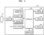
FIG. 1 is a block diagram illustrating a configuration of an ultrasound diagnosis apparatus , according to an embodiment; -
FIGS. 2A, 2B, and 2C are diagrams illustrating an ultrasound diagnosis apparatus according to an embodiment; -
FIG. 3 is a diagram illustrating a configuration of a medical imaging apparatus according to an embodiment; -
FIG. 4 is a diagram illustrating a process of estimating a parameter value, according to an embodiment; -
FIG. 5 illustrates medical images according to an embodiment; -
FIG. 6 is a diagram illustrating a configuration of a medical imaging apparatus according to an embodiment; -
FIG. 7 illustrates a graphical user interface (GUI) view according to an embodiment; -
FIG. 8 is a block diagram of a neural network processor according to an embodiment; -
FIG. 9 is a block diagram illustrating a data learner according to an embodiment; -
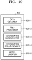
FIG. 10 is a block diagram illustrating a data determiner according to an embodiment; -
FIG. 11 illustrates an example of managing training data, according to an embodiment; and -
FIG. 12 is a flowchart of a medical imaging apparatus control method according to an embodiment. - The principles of embodiments of the disclosure will now be described and embodiments thereof will now be provided to clearly define the scope of claims and for one of ordinary skill in the art to be able to perform the present. The present disclosure may, however, be embodied in many different forms and should not be construed as being limited to the embodiments set forth herein.
- Throughout the specification, like reference numerals denote like elements. Not all elements of the embodiments are described in the specification, and general features in the art or redundant features among the embodiments are omitted. Throughout the specification, a term such as "module" or "unit" may be implemented as one of or a combination of at least two of software, hardware, and firmware. In some embodiments, a plurality of modules or a plurality of units may be implemented as one element, or a module or a unit may include a plurality of elements.
- As used herein, the term "and/or" includes any and all combinations of one or more of the associated listed items. Expressions such as "at least one of," when preceding a list of elements, modify the entire list of elements and do not modify the individual elements of the list.
- Hereinafter, embodiments of the present disclosure will now be described with reference to the accompanying drawings.
- In embodiments, an image may include any medical image acquired by various medical imaging apparatuses such as a magnetic resonance imaging (MRI) apparatus, a computed tomography (CT) apparatus, an ultrasound imaging apparatus, or an X-ray apparatus.
- Also, in the present specification, an "object", which is a thing to be imaged, may include a human, an animal, or a part thereof. For example, an object may include a part of a human, that is, an organ or a tissue, or a phantom.
- Throughout the specification, an ultrasound image refers to an image of an object processed based on ultrasound signals transmitted to the object and reflected therefrom.
- Hereinafter, embodiments will now be described with reference to the accompanying drawings.
- In the present disclosure, a medical imaging apparatus may be embodied as an MRI apparatus, a CT apparatus, an ultrasound diagnosis apparatus, or an X-ray apparatus. In the present disclosure, it is assumed that the medical imaging apparatus is an ultrasound diagnosis apparatus, but embodiments of the present disclosure are not limited to an ultrasound diagnosis apparatus.
-
FIG. 1 is a block diagram illustrating a configuration of anultrasound diagnosis apparatus 100, according to an embodiment. - Referring to
FIG. 1 , theultrasound diagnosis apparatus 100 may include aprobe 20, anultrasound transceiver 110, acontroller 120, animage processor 130, adisplay 140, astorage 150, acommunicator 160, and aninput interface 170. - The
ultrasound diagnosis apparatus 100 may be of a cart-type or portable-type ultrasound diagnosis apparatus, that is portable, moveable, mobile, or hand-held. Examples of the portable-typeultrasound diagnosis apparatus 100 may include a smartphone, a laptop computer, a personal digital assistant (PDA), a tablet personal computer (PC), or the like, each of which may include a probe and a software application, but embodiments are not limited thereto. - The
probe 20 may include a plurality of transducers. The plurality of transducers may transmit ultrasound signals to anobject 10, in response to transmitting signals received by theprobe 20, from atransmitter 113. The plurality of transducers may receive ultrasound signals reflected from theobject 10 so as to generate reception signals. In addition, theprobe 20 and theultrasound diagnosis apparatus 100 may be formed in one body (e.g., disposed in a single housing), or theprobe 20 and theultrasound diagnosis apparatus 100 may be formed separately (e.g., disposed separately in separate housings) but linked in a wired or wireless manner. In addition, theultrasound diagnosis apparatus 100 may include one ormore probes 20 according to embodiments. - The
controller 120 may control thetransmitter 113 to generate transmitting signals to be applied to each of the plurality of transducers, based on a position and a focal point of the plurality of transducers included in theprobe 20. - The
controller 120 may control areceiver 115 to generate ultrasound data by converting reception signals received from theprobe 20 from analogue to digital signals and summing the reception signals converted into digital form, based on the position and the focal point of the plurality of transducers. - The
image processor 130 may generate an ultrasound image by using ultrasound data generated by theultrasound receiver 115. - The
display 140 may display the generated ultrasound image and various pieces of information processed by theultrasound diagnosis apparatus 100. Theultrasound diagnosis apparatus 100 may include one ormore displays 140 according to embodiments. Also, thedisplay 140 may include a touchscreen in combination with a touch panel. - The
controller 120 may control operations of theultrasound diagnosis apparatus 100 and flow of signals between internal elements of theultrasound diagnosis apparatus 100. Thecontroller 120 may include a memory configured to store a program or data to perform functions of theultrasound diagnosis apparatus 100, and a processor and/or a microprocessor (not shown) to process the program or data. For example, thecontroller 120 may control operations of theultrasound diagnosis apparatus 100 by receiving a control signal from theinput interface 170 or an external apparatus. - The
ultrasound diagnosis apparatus 100 may include thecommunicator 160 and may be connected to external apparatuses, for example, servers, medical apparatuses, and portable devices such as smartphones, tablet PCs, wearable devices, or the like via thecommunicator 160. - The
communicator 160 may include at least one element capable of communicating with the external apparatuses. For example, thecommunicator 160 may include at least one of a short-range communication module, a wired communication module, and a wireless communication module. - The
communicator 160 may exchange a control signal and data with the external apparatuses. - The
storage 150 may store various data or programs for driving and controlling theultrasound diagnosis apparatus 100, input and/or output ultrasound data, obtained ultrasound images, applications, or the like. - The
input interface 170 may receive a user input to control theultrasound diagnosis apparatus 100. Examples of the user input may include an input of manipulating a button, a keypad, a mouse, a trackball, a jog switch, knob, or the like, an input of touching a touchpad or a touchscreen, a voice input, a motion input, and a bioinformation input, for example, iris recognition or fingerprint recognition, but the present disclosure is not limited thereto. - An example of the
ultrasound diagnosis apparatus 100 according to an embodiment will be described below with reference toFIGS. 2A, 2B, and 2C . -
FIGS. 2A, 2B, and 2C are diagrams illustrating an ultrasound diagnosis apparatus according to an embodiment. - Referring to
FIGS. 2A and 2B , theultrasound diagnosis apparatuses main display 121 and a sub-display 122. At least one of themain display 121 and the sub-display 122 may include a touchscreen. Themain display 121 and the sub-display 122 may display ultrasound images and/or various information processed by theultrasound diagnosis apparatuses main display 121 and the sub-display 122 may provide graphical user interfaces (GUIs), thereby receiving user inputs of data to control theultrasound diagnosis apparatuses main display 121 may display an ultrasound image and the sub-display 122 may display a control panel to control display of the ultrasound image as a GUI. The sub-display 122 may receive an input of data to control the display of an image through the control panel displayed as a GUI. Theultrasound diagnosis apparatuses main display 121 by using the input control data. - Referring to
FIG. 2B , theultrasound diagnosis apparatus 100b may include acontrol panel 165. Thecontrol panel 165 may include buttons, trackballs, jog switches, or knobs, and may receive data to control theultrasound diagnosis apparatus 100b from the user. For example, thecontrol panel 165 may include a time gain compensation (TGC) button 171 and afreeze button 172. The TGC button 171 is to set a TGC value for each depth of an ultrasound image. Also, when an input of thefreeze button 172 is detected during scanning an ultrasound image, theultrasound diagnosis apparatus 100b may keep displaying a frame image at that time point. - The buttons, trackballs, jog switches, and knobs included in the
control panel 165 may be provided as a GUI to themain display 121 or the sub-display 122. - Referring to
FIG. 2C , theultrasound diagnosis apparatus 100c may include a portable device. An example of the portableultrasound diagnosis apparatus 100c may include, for example, smart phones including probes and applications, laptop computers, personal digital assistants (PDAs), or tablet PCs, but an exemplary embodiment is not limited thereto. - The
ultrasound diagnosis apparatus 100c may include theprobe 20 and amain body 40. Themain body 40 may include atouchscreen 145. Thetouchscreen 145 may display an ultrasound image, various pieces of information processed by theultrasound diagnosis apparatus 100c, and a GUI. -
FIG. 3 is a diagram illustrating a configuration of amedical imaging apparatus 300 according to an embodiment. - The
medical imaging apparatus 300 includes aninput interface 310, aprocessor 320, anoutput interface 330, and astorage 340. Theprocessor 320 may include one or more processors and may include aneural network processor 325. - The
medical imaging apparatus 300 and a scan unit to scan an object may be embodied in one body or may be separately embodied. For example, themedical imaging apparatus 300 and theultrasound diagnosis apparatus 100 may be embodied in one body, or themedical imaging apparatus 300 may be embodied as a computer or a portable terminal configured to communicate with theultrasound diagnosis apparatus 100. Also, according to an embodiment, themedical imaging apparatus 300 may be embodied as a workstation arranged outside a scan room of a CT imaging apparatus, an MRI apparatus, or an X-ray apparatus. - The
medical imaging apparatus 300 may automatically set a parameter used by themedical imaging apparatus 300 or the scan unit. In the present disclosure, the parameter indicates a parameter for setting components of themedical imaging apparatus 300 or the scan unit, or a parameter used in processing image data. The parameter may include a gain of signal processing, a Digital Radiography (DR) index of a detector, or the like. Also, the parameter may include a TGC value, a lateral gain compensation (LGC) value, or the like of theultrasound diagnosis apparatus 100. Also, the parameter may include a window level (WL), a window width (WW), or the like of theultrasound diagnosis apparatus 100. - The
input interface 310 receives a medical image. The medical image may be raw data or a reconstructed image. Also, the medical image may be an ultrasound image, a CT image, an MRI image, or an X-ray image. - According to the present embodiment, the
input interface 310 may be implemented as a communicator. The communicator may receive the medical image from the scan unit of the scan room or an external apparatus. Theinput interface 310 may receive the medical image by using wired or wireless communication. - According to another embodiment, the
input interface 310 may be embodied as a scan unit. For example, the scan unit may be embodied as an ultrasound probe, an X-ray generator and an X-ray detector of a CT imaging apparatus, a scanner of an MRI apparatus, or an X-ray generator and an X-ray detector of an X-ray apparatus. Theinput interface 310 may obtain raw data of an imaged object. - Also, the
input interface 310 may receive a control input from a user. According to an embodiment, theinput interface 310 may receive a first control input of setting a parameter from the user. Theinput interface 310 may be embodied as a keyboard, a mouse, a touchscreen, a touch pad, a wheel, a knob, or the like. - The
processor 320 may control all operations of themedical imaging apparatus 300. Theprocessor 320 may include one or more processors and may include theneural network processor 325. According to an embodiment, theneural network processor 325 may be embodied as a separate chip. Theneural network processor 325 may include a neural network. - The
processor 320 may identify at least one image feature value from an input medical image. The at least one image feature value indicates a value obtained from the input medical image, and may include a mean, a contrast, a standard deviation, sharpness, a view type, or the like. Theprocessor 320 may obtain an image feature value of raw data or reconstructed data of an input medical image. The image feature value may configure a feature vector corresponding to the input medical image. The feature vector may correspond to a set of a plurality of image feature values. - According to an embodiment, when a control signal requesting execution of an auto scan mode is input via the
input interface 310, theprocessor 320 may perform an operation of estimating an optimal parameter. - The
processor 320 obtains a parameter value of an input medical image, based on an optimization coefficient with respect to at least one parameter stored in thestorage 340. The optimization coefficient is a coefficient for calculating at least one parameter value from at least one feature value. A function of calculating a parameter value from at least one feature value may be expressed as various forms of the function, and for example, the function may be expressed as various forms of the function, the forms including a linear function, a quadratic function, an exponential function, a logarithmic function, or the like. According to an embodiment, the optimization coefficient may indicate a weight with respect to each node of a neural network processor. - The
processor 320 may estimate at least one optimization coefficient by using new training data and pre-trained data stored in thestorage 340. The pre-trained data and the new training data may include a feature vector and a parameter value corresponding thereto. The new training data may be obtained based on a first control signal of setting at least one parameter value. For example, when the first control signal of setting an A parameter as a second value is input, a value of the A parameter corresponding to a feature vector of an input medical image is set as the second value, and a case in which the A parameter is set as the second value with respect to the feature vector may be stored as the new training data. - Also, the
processor 320 may update the optimization coefficient with respect to the at least one parameter stored in thestorage 340, based on the first control signal of setting the at least one parameter value. For example, when an optimization coefficient with respect to the A parameter is stored as a first set in thestorage 340, and the first control signal of setting the A parameter as the second value is input, theprocessor 320 may update the optimization coefficient with respect to the A parameter, based on the first control signal. In detail, theprocessor 320 may use, as the new training data, the case of setting the A parameter as the second value, may reflect the new training data thereto, and then may update the optimization coefficient with respect to the A parameter as the second set. According to an embodiment, whenever the first control signal of setting the value of the A parameter is input, the stored optimization coefficient is updated in real time, therefore, even when a preset number of training data is not accumulated, an optimization coefficient may be immediately updated, and an optimal result based on user preference may be obtained. - When the
processor 320 calculates an optimization coefficient with respect to a parameter, theprocessor 320 may use a method such as a linear least squares method, deep learning, or the like. For example, to estimate the optimization coefficient, theprocessor 320 may estimate the optimization coefficient by which a least square value with respect to the parameter value corresponding to the first control signal is calculated when the feature vector is inserted thereto. As another example, theprocessor 320 may estimate, by using deep learning, the optimization coefficient by which the parameter value corresponding to the first control signal is calculated with respect to the feature vector. - When the first control signal of setting at least one parameter value is input, the
processor 320 may set the at least one parameter value based on the first control signal, may update the medical image by using the set parameter value, and may display the updated medical image. For example, theprocessor 320 may obtain a resultant medical image while the A parameter is set as a first value, and when the first control signal of setting the A parameter as the second value is input while the obtained resultant medical image is displayed on a display, theprocessor 320 may re-obtain a resultant medical image by setting the A parameter as the second value, and may update the displayed medical image to the re-obtained resultant medical image. - The
output interface 330 may output a resultant medical image. According to an embodiment, theoutput interface 330 may include a display and may display the resultant medical image on the display. According to another embodiment, theoutput interface 330 may include a communicator, and may transmit the resultant medical image to an external apparatus by using the communicator. The external apparatus may include a user terminal, an external server, a console, or the like. Examples of the user terminal may include a smartphone, a tablet PC, a PC, or the like. - The
output interface 330 may include the display and may display a GUI on the display. Theoutput interface 330 may display the resultant medical image on the GUI. Also, theoutput interface 330 may provide a GUI for receiving an input of the first control signal. - The
storage 340 may store the pre-trained data, the new training data, and the optimization coefficient with respect to at least one parameter. -
FIG. 4 is a diagram illustrating a process of estimating a parameter value, according to an embodiment. - According to an embodiment, the
medical imaging apparatus 300 may estimate at least one parameter value from a feature vector by using theneural network processor 325. - The feature vector may include a plurality of feature values. For example, the feature vector may include at least one of an image feature value, a user feature value, a use environment feature value, an apparatus feature value, a patient feature value, and a scan feature value, or a combination thereof. According to an embodiment, raw data with respect to a feature value may be input to the
neural network processor 325, and then theneural network processor 325 may calculate the feature value from the raw data and may estimate a parameter value by using the calculated feature value. For example, image data may be input to theneural network processor 325, and theneural network processor 325 may extract an image feature value from the image data and then may obtain a parameter value by using the image feature value. - The combination of feature values included in the feature vector may vary according to each case. For example, in a case where an ultrasound image is obtained, an image feature value is obtained from the obtained ultrasound image, the
medical imaging apparatus 300 calculates a first parameter value from a first feature vector including the image feature value, and then a user feature value is input, a second feature vector including the image feature value and the user feature value may be input again to theneural network processor 325, and theneural network processor 325 may calculate a second parameter value corresponding to the second feature vector. - The
neural network processor 325 may include a plurality of layers and a plurality of nodes. The plurality of layers may include at least one of a input layer, the hidden layer, and the output layer. An optimization coefficient may be input to theneural network processor 325 and may be applied to the plurality of layers and the plurality of nodes. - The
neural network processor 325 may estimate at least one parameter value from the input feature vector. For example, theneural network processor 325 may estimate at least one of a gain, a DR index, a TGC value, and an LGC value, or a combination thereof. - The user feature value may include a user's job and user preference. The user's job may be classified into a doctor, a radiologic technologist, a nurse, a normal person, etc. The user preference may indicate preferences respectively corresponding to a plurality of pieces of identification information, based on user identification information. For example, information indicating that a user A prefers a gain of 50 and a user B prefers a gain of 48 may be considered as a feature value.
- The user feature value may be obtained by obtaining the user identification information and using user information stored in the
storage 340. According to an embodiment, themedical imaging apparatus 300 may obtain the user feature value from a user input via theinput interface 310 or an input from an external apparatus. For example, theprocessor 320 may provide a GUI for receiving the user feature value and may obtain the user feature value via the GUI. According to another embodiment, themedical imaging apparatus 300 may receive the user feature value corresponding to the user identification information from an external server. - The use environment feature value may include an intensity of illumination, a use location of a medical image, or the like. The intensity of illumination indicates an intensity of illumination of a location or place where the medical image is read. The use location of the medical image may be divided into an operating room, an examining room, an ambulance, a laboratory, or the like.
- The use environment feature value may be obtained from information stored in the
medical imaging apparatus 300, may be obtained from a sensor provided at themedical imaging apparatus 300, or may be obtained by receiving information about a use environment from an external apparatus. According to an embodiment, themedical imaging apparatus 300 may include an illumination sensor and may obtain an illumination value from a sensing value sensed by the illumination sensor. According to an embodiment, themedical imaging apparatus 300 may include a global positioning system (GPS), and may determine the use location of the medical image, based on location information obtained by the GPS. According to an embodiment, themedical imaging apparatus 300 may store information about a place where a corresponding apparatus is installed and may obtain information about the use location by using the stored information. - The apparatus feature value may include a display feature, processor performance, a manufacturer, a model name, or the like. The display feature may include a brightness feature of a display, a dynamic range feature, or the like. The apparatus feature value indicates features of an apparatus for reading a medical image. According to an embodiment, when a medical image processed by the
processor 320 is transmitted to an external apparatus via the communicator, a feature of the external apparatus is expressed as the apparatus feature value. - The apparatus feature value may be obtained based on identification information of an apparatus. For example, the
processor 320 may use an apparatus feature value stored to correspond to a serial number of the apparatus. As another example, theprocessor 320 may use an apparatus feature value stored to correspond to a manufacturer or a model name of the apparatus. For example, thestorage 340 may store a type of the apparatus (e.g., a smartphone, a tablet PC, a desktop computer, a wearable device, or the like), a display feature, or the like with respect to the serial number or the model name of the apparatus. - The patient feature value includes a medical history of a patient. For example, the patient feature value may include a region of interest (ROI), a name of disease, a disease progress, or the like of the patient. When a medical image is an ultrasound image, the patient feature value may include TGC and LGC that are appropriate for the ROI of the patient. When the medical image is a CT image, the patient feature value may include WL and WW that are appropriate for the ROI of the patient.
- The
processor 320 may receive identification information about the patient from theinput interface 310, and may obtain the patient feature value from thestorage 340 or an external apparatus. As another example, theprocessor 320 may receive the patient feature value via theinput interface 310. - The scan feature value may include an executed protocol, a type of ROI, a position of ROI, or the like. The type of ROI may be classified according to an organ corresponding to a ROI, whether the ROI moves, a type (a bone, blood, a membrane, or the like) of tissue of the ROI, or the like. The position of ROI may indicate information about in which organ a ROI is placed, a depth of the ROI, or the like.
-
FIG. 5 illustrates medical images according to an embodiment. - According to an embodiment, while a
first image 510 is obtained by using a first value of a first parameter with respect to an input medical image and is displayed, when a first control signal of setting the first parameter as a second value is input, theprocessor 320 generates asecond image 520 by setting the first parameter as the second value and outputs thesecond image 520 via theoutput interface 330. Also, theprocessor 320 not only performs a simple process of setting the first parameter as the second value but also calculates an optimization coefficient based on the first control signal and updates an optimization coefficient stored in thestorage 340. -
FIG. 6 is a diagram illustrating a configuration of amedical imaging apparatus 300a according to an embodiment. - According to an embodiment, the
medical imaging apparatus 300a may include anultrasound system 605 and aprocessor 650. Theultrasound system 605 and theprocessor 650 may be embodied in one body or may be separately embodied. - The
ultrasound system 605 may include aprobe 610 to output an ultrasound signal and detect an echo signal, a front-end 620 to process an analog signal output from theprobe 610, and a back-end 630 to process a digital signal processed by the front-end 620 and deliver the digital signal, adisplay 640 to display an ultrasound image and a GUI view, and theprocessor 650. - The
processor 650 may include animage optimizing module 660, a self-learning module 680, and amemory 670. Theimage optimizing module 660 estimates an optimal parameter with respect to an input medial image and feeds back the optimal parameter to theultrasound system 605. The self-learning module 680 receives a user-input first control signal with respect to an output medical image, and updates theimage optimizing module 660 in real time so as to output an optimal result according to user preference. - A medical image obtained via the
probe 610 is displayed in real time on thedisplay 640. When image optimization with respect to the displayed current medical image is requested by a user (operation 652), theimage optimizing module 660 performs parameter estimation based on a feature vector. - The
image optimizing module 660 extracts afeature vector 666 by extracting (operation 664) an image feature value from aninput image 662. In this regard, theinput image 662 and thefeature vector 666 are respectively stored in animage data buffer 672 and afeature vector buffer 674 of thememory 670. Theimage optimizing module 660 performs anoperation 668 of estimating a value of a parameter including a gain, DR, TGC, or the like from thefeature vector 666 stored in thefeature vector buffer 674 and anoptimization coefficient 676 of thememory 670. For theoperation 668 of estimating the value of the parameter, various methods including a linear least squares method, deep learning, or the like may be used. The estimated value of the parameter is fed back to theultrasound system 605, and a medical image whose brightness, a dynamic range, or the like is changed due to a change in the value of the parameter is displayed on thedisplay 640. - Also, according to an embodiment, the self-
learning module 680 is provided to improve theimage optimizing module 660 to operate an image optimizing function by applying user preference thereto. When a user requests execution of self-learning (operation 654), the self-learning module 680 performs self-learning for optimization. First, aGUI module 682 is executed to receive, from a user, an input of a user control signal with respect to a medical image generated based on the estimated value of the parameter. Image data stored in theimage data buffer 672 of thememory 670 is input to theGUI module 682, and theGUI module 682 displays, on thedisplay 640, multi-view images of various values of the parameter. - The
image optimizing module 660 combines a parameter value with a pre-trained feature value and stores a combined value as a new feature value in thefeature vector buffer 674, wherein the parameter value is based on user preference input via theGUI module 682 and the pre-trained feature value is stored in thefeature vector buffer 674. The self-learning module 680 performs an optimizationcoefficient updating process 684 by using the new feature value stored in thefeature vector buffer 674 and the pre-trained feature value that is preset in a factory during the manufacture, and stores the updatedoptimization coefficient 676 in thememory 670. The optimizationcoefficient updating process 684 is performed in real time and is applied when next image optimization is performed. -
FIG. 7 illustrates a GUI view according to an embodiment. - The
processor 320 may provide a GUI for receiving a first control signal of setting a parameter value. According to an embodiment, as illustrated inFIG. 7 , the GUI view may display amedical image 712, and may include the GUI for receiving a first control signal of setting a parameter value. The GUI view may include afirst area 710 and asecond area 720. - The
first area 710 displays a plurality of themedical images 712 generated by using candidate parameter values, and provides the GUI for receiving a first control signal of selecting one of the displayed plurality ofmedical images 712. For example, thefirst area 710 may include nine candidatemedical images 712 generated by applying three candidate values with respect to aparameter 1 and three candidate values with respect to aparameter 2 to an input medical image. - The
processor 320 may identify respective optimal parameter values of theparameter 1 and theparameter 2, and may determine a plurality of candidate values based on the optimal parameter values. For example, theprocessor 320 may determine a plurality of candidate values with respect to an optimal parameter value at a preset interval. - Also, the
processor 320 may generate the candidatemedical images 712 by applying the candidate values with respect to theparameter 1 and theparameter 2 to the input medical image. For example, when theparameter 1 is a gain and theparameter 2 is a DR index, theprocessor 320 may determine a preset number of candidate values with respect to a value of the gain, may determine a preset number of candidate values with respect to the DR index, and may generate the candidatemedical images 712 by using the candidate values with respect to the gain and the DR index. For example, a first candidatemedical image 712a is generated by applying a gain value of 48 and a DR index of 48 thereto, a second candidatemedical image 712b is generated by applying a gain value of 50 and a DR index of 48 thereto, and a third candidatemedical image 712c is generated by applying a gain value of 52 and a DR index of 48 thereto. - The
processor 320 may identify a value of theparameter 1 and a value of theparameter 2, in response to a first control signal of selecting one of the candidatemedical images 712. For example, when a user selects the second candidatemedical image 712b, theprocessor 320 may identify the value of theparameter 1 to be 50 and the value of theparameter 2 to be 48. - According to an embodiment, the
processor 320 may adjust the value of theparameter 1 and the value of theparameter 2, according to a selected position on the candidatemedical image 712. For example, when the first control signal selects a position of anarrow 1 714 on the second candidatemedical image 712b, theprocessor 320 may identify the value of theparameter 1 to be 50.5 and the value of theparameter 2 to be 48.5. According to the present embodiment, a parameter value may be finely adjusted in one candidatemedical image 712, therefore, a user may further accurately designate a parameter value. - The
second area 720 indicates a plurality of candidate values 722 with respect to aparameter 3 corresponding to a set of a plurality of values. The set of the plurality of values of theparameter 3 may be expressed as a graph. Theparameter 3 may correspond to a TGC value, an LGC value, or the like. Thesecond area 720 may include a plurality ofcandidate graphs 724. Theprocessor 320 may generate an optimal graph of theparameter 3, based on a feature vector, and then may generate the plurality ofcandidate graphs 724 based on the optimal graph. In response to a first control signal of selecting one of a plurality of candidate values 722, theprocessor 320 may determine a selectedcandidate value 722 to be a value of theparameter 3. - According to an embodiment, the
second area 720 may providecurve adjustment Uls candidate value 722. According to an embodiment, thecurve adjustment Uls icons curve 724a, and when positions of theicons curve adjustment Uls curve 724a to correspond to the changed positions of theicons icons reference lines - According to an embodiment, only one of the
first area 710 and thesecond area 720 may be provided to a GUI. Types of parameters that may be adjusted in thefirst area 710 or thesecond area 720 may be preset or may be determined according to user selection. - Arrangements of the
first area 710 and thesecond area 720 illustrated inFIG. 7 may be an example, and in another embodiment, sizes, forms, designs, or the like of thefirst area 710 and thesecond area 720 may be changed. - According to an embodiment, the
processor 320 may provide a GUI for inputting a feature value. For example, the GUI for inputting a feature value may be provided with a GUI for selecting a parameter value. The GUI for inputting a feature value may provide a UI for receiving an input of a user feature value, a use environment feature value, an apparatus feature value, a patient feature value, a scan feature value, or the like. -
FIG. 8 is a block diagram of aneural network processor 325a according to an embodiment. - Referring to
FIG. 8 , theneural network processor 325a according to an embodiment may include adata trainer 810 and adata determiner 820. - The
data trainer 810 may learn a criterion for determining a situation. Thedata trainer 810 may learn a criterion about which data is to be used to determine a certain situation and about how to determine a certain situation by using data. Thedata trainer 810 may obtain data to be used in learning, may apply the obtained data to a data determination model to be described below, and thus may learn the criterion for determining a situation. - The data determiner 820 may determine a situation, based on data. The data determiner 820 may determine the situation, based on certain data, by using a trained data determination model. The data determiner 820 may obtain certain data, based on a criterion that is preset due to training, and may determine a certain situation, based on the certain data, by using the data determination model by using the obtained data as an input value. A resultant value output via the data determination model by using the obtained data as the input value may be used in updating the data determination model.
- At least one of the
data trainer 810 and thedata determiner 820 may be embodied as at least one hardware chip and may be mounted in themedical imaging apparatus 300. For example, at least one of thedata trainer 810 and thedata determiner 820 may be embodied as a dedicated hardware chip for artificial intelligence (Al), or may be embodied as a part of a general-use processor (e.g., a central processing unit (CPU) or an application processor) or a graphic-dedicated processor (e.g., a graphics processing unit (GPU) and may be mounted in themedical imaging apparatus 300. - In this case, the
data trainer 810 and thedata determiner 820 may be mounted together in themedical imaging apparatus 300, or may be embodied separately in respective apparatuses. For example, one of thedata trainer 810 and thedata determiner 820 may be included in themedical imaging apparatus 300 and the other one may be included in a server. Also, thedata trainer 810 and thedata determiner 820 may communicate with each other in a wired or wireless manner, such that model information established by thedata trainer 810 may be provided to thedata determiner 820, and data input to thedata determiner 820 may be provided, as additional training data, to thedata trainer 810. - At least one of the
data trainer 810 and thedata determiner 820 may be embodied as a software module. When at least one of thedata trainer 810 and thedata determiner 820 is embodied as a software module (or a program module including instructions), the software module may be stored in a non-transitory computer-readable recording medium. In this case, one or more software modules may be provided by an operating system (OS) or a certain application. Alternatively, some of the one or more software modules may be provided by the OS and the rest of the one or more software modules may be provided by a certain application. -
FIG. 9 is a block diagram illustrating thedata trainer 810 according to an embodiment. - Referring to
FIG. 9 , thedata trainer 810 according to an embodiment may include a data obtainer 810-1, a pre-processor 810-2, a training data selector 810-3, a model trainer 810-4, and a model evaluator 810-5. - The data obtainer 810-1 may obtain data necessary for determination of situation. The data obtainer 810-1 may obtain data required in training for determination of situation. For example, the data obtainer 810-1 may obtain raw data, a feature value, a first control signal, or the like to obtain a feature value vector.
- The pre-processor 810-2 may pre-process the obtained data to make the obtained data used in training for determination of situation. The pre-processor 810-2 may process the obtained data to have a preset format so as to allow the model trainer 810-4 to use the obtained data in training for determination of situation.
- The training data selector 810-3 may select, from among the pre-processed data, data required in training. The selected data may be provided to the model trainer 810-4. The training data selector 810-3 may select, from among the pre-processed data, the data required in training, according to a preset criterion for determination of situation. Also, the training data selector 810-3 may select data according to a criterion that is preset via training by the model trainer 810-4 to be described below.
- The model trainer 810-4 may learn a criterion about how to determine a situation, based on training data. Also, the model trainer 810-4 may learn a criterion about which training data is to be used to determine a situation
- Also, the model trainer 810-4 may train, by using training data, a data determination model to be used in determination of situation. In this case, the data determination model may be a pre-established model. For example, the data determination model may be a model that has been pre-established by receiving default training data (e.g., a sample image, or the like).
- The data determination model may be established, in consideration of an application field of a determination model, an objective of training, a computing capability of an apparatus, or the like. The data determination model may be a model based on a neural network. For example, models including a deep neural network (DNN), a recurrent neural network (RNN), a bidirectional recurrent deep neural network (BRDNN), or the like may be used as the data determination model, but the present disclosure is not limited thereto.
- According to various embodiments, when there are a plurality of pre-established data determination models, the model trainer 810-4 may determine, as a data determination model to train, a data determination model having a high relation between input training data and default training data. In this case, the default training data may be pre-classified according to types of data, and data determination models may be pre-established according to the types of data. For example, the default training data may be pre-classified according to various criteria including an area where training data is generated, a time when training data is generated, a size of training data, a genre of training data, a generator of training data, types of an object in training data, or the like.
- Also, the model trainer 810-4 may train a data determination model by using a training algorithm including an error back-propagation algorithm, a gradient descent gradient descent, or the like.
- Also, the model trainer 810-4 may train a data determination model by supervised learning using training data as an input value. Also, the model trainer 810-4 may train a data determination model by unsupervised learning in which a criterion for determination of situation is found by self-learning a type of data necessary for determination of situation without supervision. Also, the model trainer 810-4 may train a data determination model by reinforcement learning using a feedback about whether a result of determining a situation according to training is correct.
- When a data determination model is trained, the model trainer 810-4 may store the trained data determination model. In this case, the model trainer 810-4 may store the trained data determination model in a memory of the
medical imaging apparatus 300 including thedata determiner 820. Alternatively, the model trainer 810-4 may store the trained data determination model in a memory of a server that is connected to themedical imaging apparatus 300 via a wired or wireless network. - In this case, the memory that stores the trained data determination model may also store, for example, a command or data related with at least one other component of the
medical imaging apparatus 300. The memory may also store software and/or a program. The program may include, for example, a kernel, a middleware, an application programming interface (API), and/or an application program (or an application). - The model evaluator 810-5 may input evaluation data to a data determination model, and when a determination result output from the evaluation data does not satisfy a certain criterion, the model evaluator 810-5 may allow the model trainer 810-4 to train the data determination model again. In this case, the evaluation data may be preset data for evaluating a data determination model.
- For example, when the number or a rate of the evaluation data whose determination result is not correct is greater than a preset threshold value, the determination result being from among determination results of the data determination model trained with respect to the evaluation data, the model evaluator 810-5 may evaluate that the certain criterion is not satisfied. For example, in a case where the certain criterion is defined as a rate of 2 %, when the trained data determination model outputs incorrect determination results for at least 20 items of evaluation data among a total of 1000 items of evaluation data, the model evaluator 810-5 may evaluate that the trained data determination model is not appropriate.
- When there are a plurality of trained data determination models, the model evaluator 810-5 may evaluate whether each of trained data determination models satisfies the certain criterion, and may determine a model to be a final data determination model, the model satisfying the certain criterion. In this case, when the model satisfying the certain criterion is plural in number, the model evaluator 810-5 may determine, as the final data determination model, one model or a certain number of models which are preset according to their respective high evaluation scores.
- At least one of the data obtainer 810-1, the pre-processor 810-2, the training data selector 810-3, the model trainer 810-4, and the model evaluator 810-5 in the
data trainer 810 may be embodied as at least one hardware chip and may be mounted in themedical imaging apparatus 300. For example, at least one of the data obtainer 810-1, the pre-processor 810-2, the training data selector 810-3, the model trainer 810-4, and the model evaluator 810-5 may be embodied as a dedicated hardware chip for Al, or may be embodied as a part of a general-use processor (e.g., a CPU or an application processor) or a graphic-dedicated processor (e.g., a GPU and may be mounted in themedical imaging apparatus 300. - In this case, the data obtainer 810-1, the pre-processor 810-2, the training data selector 810-3, the model trainer 810-4, and the model evaluator 810-5 may be mounted together in one apparatus, or may be embodied separately in respective apparatuses. For example, some of the data obtainer 810-1, the pre-processor 810-2, the training data selector 810-3, the model trainer 810-4, and the model evaluator 810-5 may be included in the
medical imaging apparatus 300 and the others may be included in a server. - At least one of the data obtainer 810-1, the pre-processor 810-2, the training data selector 810-3, the model trainer 810-4, and the model evaluator 810-5 may be embodied as a software module. When at least one of the data obtainer 810-1, the pre-processor 810-2, the training data selector 810-3, the model trainer 810-4, and the model evaluator 810-5 is embodied as a software module (or a program module including instructions), the software module may be stored in a non-transitory computer-readable recording medium. In this case, one or more software modules may be provided by an OS or a certain application. Alternatively, some of the one or more software modules may be provided by the OS and the rest of the one or more software modules may be provided by a certain application.
-
FIG. 10 is a block diagram illustrating thedata determiner 820 according to an embodiment. - Referring to
FIG. 10 , thedata determiner 820 according to an embodiment may include a data obtainer 820-1, a pre-processor 820-2, a determination data selector 820-3, a determination result provider 820-4, and a model updater 820-5. - The data obtainer 820-1 may obtain data necessary for determination of situation, and the pre-processor 820-2 may pre-process the obtained data to make the obtained data used in determination of situation. The pre-processor 820-2 may process the obtained data to have a preset format so as to allow the determination result provider 820-4 to use the obtained data for determination of situation.
- The determination data selector 820-3 may select, from among the pre-processed data, data necessary for determination of situation. The selected data may be provided to the determination result provider 820-4. The determination data selector 820-3 may select all or some of the pre-processed data, according to a preset criterion for determination of situation. Also, the determination data selector 820-3 may select data according to a criterion that is preset via training by the model trainer 810-4 described above.
- The determination result provider 820-4 may determine a situation by applying the selected data to a data determination model. The determination result provider 820-4 may provide a determination result according to a determination objective with respect to the data. The determination result provider 820-4 may apply the selected data to the data determination model by using, as an input value, the data selected by the determination data selector 820-3. Also, the determination result may be determined by the data determination model.
- The model updater 820-5 may allow the data determination model to be updated, based on evaluation of the determination result provided by the determination result provider 820-4. For example, the model updater 820-5 may allow the data determination model to be updated by the model trainer 810-4 by providing, to the model trainer 810-4, the determination result provided by the determination result provider 820-4.
- At least one of the data obtainer 820-1, the pre-processor 820-2, the determination data selector 820-3, the determination result provider 820-4, and the model updater 820-5 in the
data determiner 820 may be embodied as at least one hardware chip and may be mounted in themedical imaging apparatus 300. For example, at least one of the data obtainer 820-1, the pre-processor 820-2, the determination data selector 820-3, the determination result provider 820-4, and the model updater 820-5 may be embodied as a dedicated hardware chip for Al, or may be embodied as a part of a general-use processor (e.g., a CPU or an application processor) or a graphic-dedicated processor (e.g., a GPU and may be mounted in themedical imaging apparatus 300. - In this case, the data obtainer 820-1, the pre-processor 820-2, the determination data selector 820-3, the determination result provider 820-4, and the model updater 820-5 may be mounted together in one apparatus, or may be embodied separately in respective apparatuses. For example, some of the data obtainer 820-1, the pre-processor 820-2, the determination data selector 820-3, the determination result provider 820-4, and the model updater 820-5 may be included in the
medical imaging apparatus 300 and the others may be included in a server. - At least one of the data obtainer 820-1, the pre-processor 820-2, the determination data selector 820-3, the determination result provider 820-4, and the model updater 820-5 may be embodied as a software module. When at least one of the data obtainer 820-1, the pre-processor 820-2, the determination data selector 820-3, the determination result provider 820-4, and the model updater 820-5 is embodied as a software module (or a program module including instructions), the software module may be stored in a non-transitory computer-readable recording medium. In this case, one or more software modules may be provided by an OS or a certain application. Alternatively, some of the one or more software modules may be provided by the OS and the rest of the one or more software modules may be provided by a certain application.
-
FIG. 11 illustrates an example of managing training data, according to an embodiment. - According to an embodiment, the
medical imaging apparatus 300 may independently manage training data and an optimization coefficient with respect to a preset feature value. The preset feature value may be at least one of a user feature, a use environment feature, an apparatus feature, a patient feature, and a scan control feature. For example, themedical imaging apparatus 300 may independently manage an optimization coefficient according to each of users. To do so, themedical imaging apparatus 300 may independently manage training data according to each of users, and may calculate an optimization coefficient based on training data of each of users. When the optimization coefficient and the training data are managed according to each of users, the optimization coefficient and the training data may be separately managed according to user identification information. - The
medical imaging apparatus 300 may manage the training data and the optimization coefficient by allocating first andsecond work areas storage 340, the first andsecond work areas FIG. 11 illustratestraining data 1112 where an estimated parameter value and a user-designated parameter value in response to a first control signal are matched. According to an embodiment, themedical imaging apparatus 300 may allocate amain work area 1110, thefirst work area 1120, and thesecond work area 1130 to thestorage 340. Themain work area 1110 may store and manage thetraining data 1112 and anoptimization coefficient 1114 regardless of a feature value. Thefirst work area 1120 may store and managetraining data 1122 and anoptimization coefficient 1124 for a first user. Thesecond work area 1130 may store and managetraining data 1132 and anoptimization coefficient 1134 for a second user. In response to an input of a first control signal with respect to the first user, theprocessor 320 stores corresponding training data in thefirst work area 1120, and updates theoptimization coefficient 1124, based on the training data in thefirst work area 1120. In response to an input of the first control signal with respect to the second user, theprocessor 320 stores corresponding training data in thesecond work area 1130, and updates theoptimization coefficient 1134, based on the training data in thesecond work area 1130. Themain work area 1110 may include pre-trained data and new training data, and thefirst work area 1120 and thesecond work area 1130 may each include new training data. -
FIG. 12 is a flowchart of a medical imaging apparatus control method according to an embodiment. - The medical imaging apparatus control method according to the present embodiment may be performed by one of various medical imaging apparatuses. In the present embodiment, it is assumed that the
medical imaging apparatus 300 according to the one or more embodiments performs the medical imaging apparatus control method, but the present embodiment is not limited thereto. The one or more embodiments of themedical imaging apparatus 300 which are disclosed in the present disclosure may be applied to the medical imaging apparatus control method, and one or more embodiments of the medical imaging apparatus control method may be applied to themedical imaging apparatus 300. - The
medical imaging apparatus 300 identifies a feature value from a medical image (S1202). Themedical imaging apparatus 300 may obtain an image feature value from the medical image. - Next, the
medical imaging apparatus 300 may identify a parameter value based on the image feature value and an optimization coefficient, by using the neural network processor 325 (e.g., a deep neural network processor) (S1204). - The
medical imaging apparatus 300 may output a resultant medical image generated based on the identified parameter value (S1206). For example, themedical imaging apparatus 300 may display the resultant medical image or may transmit the resultant medical image to an external apparatus via the communicator. - The
medical imaging apparatus 300 may receive a first control input of adjusting the parameter value (S1208), and may set a parameter value based on the first control input. - Also, the
medical imaging apparatus 300 may update the optimization coefficient by using the parameter value as training data, the parameter value being set in response to the first control input (S1210). - According to the embodiments, it is possible to improve a function of automatically setting parameters in a medical imaging apparatus.
- Also, according to the embodiments, it is possible to automatically identify an appropriate parameter, in consideration of a user, a use environment, an apparatus used by the user, patient information, a protocol, or the like.
- Also, according to the embodiments, it is possible to decrease a need for development manpower, a development period, and development costs of a medical imaging apparatus by simplifying initial settings of the medical imaging apparatus.
- The embodiments may be implemented in a software program including instructions stored in a computer-readable storage medium.
- The computer is a device capable of calling the stored instructions from the storage medium and operating according to the embodiments in accordance with the called instructions, and may include the ultrasound diagnosis apparatus according to the embodiments.
- The computer-readable storage medium may be provided in the form of a non-transitory storage medium. Here, the term 'non-transitory' means that the storage medium is tangible and does not refer to a transitory electrical signal, but does not distinguish that data is stored semi-permanently or temporarily on the storage medium.
- Furthermore, the medical imaging apparatus and the medical imaging apparatus control method according to the embodiments may be provided in a computer program product. The computer program product may be traded between a seller and a purchaser as a commodity.
- The computer program product may include a software program and a computer-readable storage medium having stored thereon the software program. For example, the computer program product may include a product (e.g. a downloadable application) in a software program distributed electronically through a manufacturer of the medical imaging apparatus or an electronic market (e.g., Google Play Store and App Store). For electronic distribution, at least a part of the software program may be stored on the storage medium or may be generated temporarily. In this case, the storage medium may be a storage medium of a server of the manufacturer, a server of the electronic market, or a relay server for temporarily storing the software program.
- The computer program product may include a storage medium of a server or a storage medium of a terminal, in a system including the server and the terminal (e.g., the ultrasound diagnosis apparatus). Alternatively, when there is a third device (e.g., a smartphone) that communicates with the server or the terminal, the computer program product may include a storage medium of the third device. Alternatively, the computer program product may include a software program that is transmitted from the server to the terminal or the third device or from the third device to the terminal.
- In this case, one of the server, the terminal, and the third device may perform the method according to the embodiments by executing the computer program product. Alternatively, at least two of the server, the terminal, and the third device may divide and perform the method according to the embodiments by executing the computer program product.
- For example, the server (e.g., a cloud server, an AI server, or the like) may execute the computer program product stored in the server, thereby controlling the terminal to perform the method according to the embodiments, the terminal communicating with the server.
- As another example, the third device may execute the computer program product, thereby controlling the terminal to perform the method according to the embodiments, the terminal communicating with the terminal. In detail, the third device may remotely control the ultrasound diagnosis apparatus, thereby controlling the ultrasound diagnosis apparatus to irradiate an ultrasound signal to an object and to generate an image of an inside part of the object, based on information of a signal reflected from the object,
- As another example, the third device may directly perform, by executing the computer program product, the method according to the embodiments based on a value input from an auxiliary device (e.g., a probe of a medical apparatus). In detail, the auxiliary device may irradiate an ultrasound signal to an object and may obtain an ultrasound signal reflected from the object. The third device may receive an input of signal information about the reflected ultrasound signal from the auxiliary device, and may generate an image of an inside part of the object, based on the input signal information.
- When the third device executes the computer program product, the third device may download the computer program product from the server, and may execute the downloaded computer program product. Alternatively, the third device may perform the method according to the embodiments by executing a pre-loaded computer program product.
Claims (15)
- A medical imaging apparatus comprising:a storage configured to store training data and an optimization coefficient;at least one processor configured to identify at least one image feature value from an input medical image, and to identify a value of at least one parameter of the medical imaging apparatus, based on the at least one image feature value and the optimization coefficient, by using a neural network processor;an output interface configured to output a resultant image generated based on the value of the at least one parameter; andan input interface configured to receive a first control input of adjusting the value of the at least one parameter,wherein the at least one processor is further configured to update the optimization coefficient by performing training using the training data and the first control input.
- The medical imaging apparatus of claim 1, wherein the at least one processor is further configured to identify the value of the at least one parameter by using at least one user feature value of the medical imaging apparatus as an input value to be input to the neural network processor.
- The medical imaging apparatus of any one of the preceding claims, wherein the at least one processor is further configured to identify the value of the at least one parameter by using a use environment feature value of the medical imaging apparatus as an input value to be input to the neural network processor.
- The medical imaging apparatus of any one of the preceding claims, wherein the at least one processor is further configured to identify the value of the at least one parameter by using an apparatus feature value corresponding to the medical imaging apparatus as an input value to be input to the neural network processor.
- The medical imaging apparatus of any one of the preceding claims, wherein the at least one processor is further configured to identify the value of the at least one parameter by using a patient feature value corresponding to an object of the medical imaging apparatus as an input value to be input to the neural network processor.
- The medical imaging apparatus of any one of the preceding claims, wherein the at least one processor is further configured to identify the value of the at least one parameter by using a scan control feature value of the medical imaging apparatus as an input value to be input to the neural network processor,
wherein the scan control feature value comprises at least one of a protocol, a type of a region of interest (ROI), and a position of the ROI, or a combination thereof. - The medical imaging apparatus of any one of the preceding claims, wherein the at least one processor is further configured to provide a graphical user interface (GUI) configured to receive the first control input,
wherein an interface view of the GUI comprises a plurality of candidate medical images generated by using respective candidate values with respect to the at least one parameter, and
wherein, in response to the first control input of selecting one of the plurality of candidate medical images, the at least one processor is further configured to identify a candidate value as the value of the at least one parameter, the candidate value corresponding to the selected candidate medical image. - The medical imaging apparatus of claim 7, wherein the at least one parameter comprises a first parameter corresponding to a set of a plurality of values,
wherein the interface view comprises a plurality of candidate graphs indicating the set of the plurality of values corresponding to the first parameter, and
wherein, in response to the first control signal of selecting one of the plurality of candidate graphs, the at least one processor is further configured to identify the selected candidate graph as the value of the at least one parameter. - The medical imaging apparatus of any one of the preceding claims, wherein the optimization coefficient comprises respective optimization coefficients with respect to a plurality of values of a first feature,
wherein the first feature is one of a user feature, a use environment feature, an apparatus feature, a patient feature, and a scan control feature. - The medical imaging apparatus of any one of the preceding claims, wherein the at least one processor is further configured to store, in the storage, the updated optimization coefficient, and to store, as the training data in the storage, the at least one image feature value and the at least one parameter which corresponds to the first control input.
- A medical imaging apparatus control method comprising:identifying at least one image feature value from an input medical image;identifying a value of at least one parameter of the medical imaging apparatus, based on the at least one image feature value and an optimization coefficient, by using a neural network processor;outputting a resultant image generated based on the value of the at least one parameter;receiving a first control input of adjusting the value of the at least one parameter; andupdating the optimization coefficient by performing training using the training data and the first control input.
- The medical imaging apparatus control method of claim 11, further comprising identifying the value of the at least one parameter by using at least one user feature value of the medical imaging apparatus as an input value to be input to the neural network processor.
- The medical imaging apparatus control method of any one of claims 11-12, further comprising identifying the value of the at least one parameter by using a use environment feature value of the medical imaging apparatus as an input value to be input to the neural network processor.
- The medical imaging apparatus control method of any one of claims 11-13, further comprising identifying the value of the at least one parameter by using an apparatus feature value corresponding to the medical imaging apparatus as an input value to be input to the neural network processor.
- A computer program comprising computer program codes for performing a medical imaging apparatus control method, the medical imaging apparatus control method comprising:identifying at least one image feature value from an input medical image;identifying a value of at least one parameter of the medical imaging apparatus, based on the at least one image feature value and an optimization coefficient, by using a neural network processor;outputting a resultant image generated based on the value of the at least one parameter;receiving a first control input of adjusting the value of the at least one parameter; andupdating the optimization coefficient by performing training using training data and the first control input.
Applications Claiming Priority (1)
| Application Number | Priority Date | Filing Date | Title |
|---|---|---|---|
| KR1020180031126A KR102656543B1 (en) | 2018-03-16 | 2018-03-16 | Medical imaging apparatus, method for controlling the same, and computer program |
Publications (2)
| Publication Number | Publication Date |
|---|---|
| EP3540740A1 true EP3540740A1 (en) | 2019-09-18 |
| EP3540740B1 EP3540740B1 (en) | 2025-07-30 |
Family
ID=65729166
Family Applications (1)
| Application Number | Title | Priority Date | Filing Date |
|---|---|---|---|
| EP19161521.0A Active EP3540740B1 (en) | 2018-03-16 | 2019-03-08 | Medical imaging apparatus, medical imaging apparatus control method, and computer program product |
Country Status (3)
| Country | Link |
|---|---|
| US (1) | US11331081B2 (en) |
| EP (1) | EP3540740B1 (en) |
| KR (1) | KR102656543B1 (en) |
Cited By (1)
| Publication number | Priority date | Publication date | Assignee | Title |
|---|---|---|---|---|
| EP3828894A1 (en) * | 2019-11-27 | 2021-06-02 | Siemens Healthcare GmbH | Medical user interface |
Families Citing this family (13)
| Publication number | Priority date | Publication date | Assignee | Title |
|---|---|---|---|---|
| JP6818424B2 (en) * | 2016-04-13 | 2021-01-20 | キヤノン株式会社 | Diagnostic support device, information processing method, diagnostic support system and program |
| US10878311B2 (en) * | 2018-09-28 | 2020-12-29 | General Electric Company | Image quality-guided magnetic resonance imaging configuration |
| KR102248444B1 (en) * | 2019-06-10 | 2021-05-04 | 포항공과대학교 산학협력단 | Method of generating ultrasonic image and apparatuses performing the same |
| US20210096934A1 (en) * | 2019-10-01 | 2021-04-01 | Shanghai United Imaging Intelligence Co., Ltd. | Systems and methods for enhancing a patient positioning system |
| US12653501B2 (en) * | 2019-12-18 | 2026-06-16 | Koninklijke Philips N.V. | Ultrasound image acquisition and processing preset sharing, and associated systems, devices, and methods |
| CN113126871A (en) * | 2019-12-30 | 2021-07-16 | 无锡祥生医疗科技股份有限公司 | Gain adjustment method, system and storage medium |
| KR102313661B1 (en) * | 2020-12-30 | 2021-10-19 | 뉴로핏 주식회사 | Method for, device for, and system for analazing medical image considering a feature information |
| USD977113S1 (en) * | 2021-04-01 | 2023-01-31 | Classys Inc. | Ultrasound therapy device |
| USD977114S1 (en) * | 2021-04-01 | 2023-01-31 | Classys Inc. | High frequency therapy device |
| JP2025517107A (en) * | 2022-05-03 | 2025-06-03 | クォンティブリー インコーポレイテッド | Identifying medical imaging protocols based on radiology data and metadata |
| CN114757852B (en) * | 2022-05-17 | 2025-09-26 | 北京联影智能影像技术研究院 | Ultrasonic image gain compensation method, device, equipment and medium |
| WO2024040218A1 (en) | 2022-08-18 | 2024-02-22 | Quantivly Inc. | Smart radiology imaging appointment scheduling |
| KR102798782B1 (en) | 2023-08-11 | 2025-04-18 | 고려대학교 산학협력단 | Device and method for accelerated magnetic resonance imaging based on a cascade of preconditioned conjugate gradient networks |
Citations (2)
| Publication number | Priority date | Publication date | Assignee | Title |
|---|---|---|---|---|
| US20060079778A1 (en) * | 2004-10-07 | 2006-04-13 | Zonare Medical Systems, Inc. | Ultrasound imaging system parameter optimization via fuzzy logic |
| US20170103512A1 (en) * | 2015-10-13 | 2017-04-13 | Siemens Healthcare Gmbh | Learning-based framework for personalized image quality evaluation and optimization |
Family Cites Families (15)
| Publication number | Priority date | Publication date | Assignee | Title |
|---|---|---|---|---|
| DE10324908B4 (en) | 2003-05-30 | 2007-03-22 | Siemens Ag | Self-learning method for image processing of digital X-ray images and associated device |
| JP2005040301A (en) | 2003-07-28 | 2005-02-17 | Toshiba Corp | Ultrasonic diagnostic apparatus and diagnostic parameter setting method thereof |
| JP5854561B2 (en) | 2009-11-27 | 2016-02-09 | カデンス メディカル イメージング インコーポレイテッド | Image data filtering method, image data filtering system, and use of image data in virtual endoscopy |
| JP5822756B2 (en) | 2012-02-28 | 2015-11-24 | 株式会社日立製作所 | Image quality evaluation method and apparatus for ultrasonic imaging apparatus |
| KR101630761B1 (en) | 2012-09-24 | 2016-06-15 | 삼성전자주식회사 | Ultrasound apparatus and method for providing information using the ultrasound apparatus |
| JP6466442B2 (en) | 2013-11-13 | 2019-02-06 | コーニンクレッカ フィリップス エヌ ヴェKoninklijke Philips N.V. | Hierarchical self-learning system for computerized clinical diagnosis support |
| EP3081166A4 (en) | 2013-12-09 | 2017-08-30 | Alpinion Medical Systems Co., Ltd. | Method and device for adjusting setting values of ultrasound image |
| US10420533B2 (en) | 2014-11-04 | 2019-09-24 | Samsung Electronics Co., Ltd. | Ultrasound diagnosis apparatus and control method thereof |
| KR102411600B1 (en) | 2014-11-04 | 2022-06-22 | 삼성전자주식회사 | Ultrasound diagnosis apparatus and control method thereof |
| KR102372214B1 (en) | 2015-01-19 | 2022-03-14 | 삼성전자주식회사 | Image processing apparatus, medical image apparatus and image processing method |
| KR102426784B1 (en) | 2015-05-29 | 2022-07-29 | 삼성전자주식회사 | Ultrasound apparatus and method for displaying ultrasoudn images |
| US10682122B2 (en) | 2015-12-03 | 2020-06-16 | Siemens Medical Solutions Usa, Inc. | Image-based user interface for controlling medical imaging |
| KR20170098481A (en) * | 2016-02-22 | 2017-08-30 | 주식회사 힐세리온 | Parameter auto setting for portable ultrasound device |
| KR101946576B1 (en) * | 2016-12-23 | 2019-02-11 | 삼성전자주식회사 | Apparatus and method for processing medical image, and computer readable recording medium related to the method |
| CN109833061B (en) | 2017-11-24 | 2020-08-04 | 无锡祥生医疗科技股份有限公司 | A method for optimizing ultrasound imaging system parameters based on deep learning |
-
2018
- 2018-03-16 KR KR1020180031126A patent/KR102656543B1/en active Active
-
2019
- 2019-03-08 EP EP19161521.0A patent/EP3540740B1/en active Active
- 2019-03-15 US US16/354,571 patent/US11331081B2/en active Active
Patent Citations (2)
| Publication number | Priority date | Publication date | Assignee | Title |
|---|---|---|---|---|
| US20060079778A1 (en) * | 2004-10-07 | 2006-04-13 | Zonare Medical Systems, Inc. | Ultrasound imaging system parameter optimization via fuzzy logic |
| US20170103512A1 (en) * | 2015-10-13 | 2017-04-13 | Siemens Healthcare Gmbh | Learning-based framework for personalized image quality evaluation and optimization |
Cited By (2)
| Publication number | Priority date | Publication date | Assignee | Title |
|---|---|---|---|---|
| EP3828894A1 (en) * | 2019-11-27 | 2021-06-02 | Siemens Healthcare GmbH | Medical user interface |
| US11721431B2 (en) | 2019-11-27 | 2023-08-08 | Siemens Healthcare Gmbh | Medical user interface |
Also Published As
| Publication number | Publication date |
|---|---|
| US20190282214A1 (en) | 2019-09-19 |
| KR20190109141A (en) | 2019-09-25 |
| US11331081B2 (en) | 2022-05-17 |
| KR102656543B1 (en) | 2024-04-12 |
| EP3540740B1 (en) | 2025-07-30 |
Similar Documents
| Publication | Publication Date | Title |
|---|---|---|
| EP3540740B1 (en) | Medical imaging apparatus, medical imaging apparatus control method, and computer program product | |
| CN111184534B (en) | Ultrasonic diagnostic device for determining abnormalities of the fetal heart and method of operating the same | |
| CN111297394B (en) | Ultrasonic imaging device, control method thereof, and recording medium | |
| EP3420913B1 (en) | Ultrasound imaging apparatus and control method thereof | |
| US20230062672A1 (en) | Ultrasonic diagnostic apparatus and method for operating same | |
| KR102557389B1 (en) | Ultrasound Imaging Apparatus and Controlling Method Thereof | |
| EP3851052B1 (en) | Ultrasound diagnosis apparatus and operating method for the same | |
| KR20200140683A (en) | Apparatus and method for aligning ultrasound image and 3D medical image | |
| EP3705050A1 (en) | Ultrasound imaging apparatus, method of controlling the same, and computer program product | |
| EP3360485A1 (en) | Ultrasonic diagnostic apparatus and control method of ultrasonic diagnostic apparatus | |
| KR20250013272A (en) | Ultrasound diagnostic apparatus and method for operating the same | |
| EP3520704B1 (en) | Ultrasound diagnosis apparatus and method of controlling the same | |
| CN110678127B (en) | System and method for adaptively enhancing vascular imaging | |
| EP3545850B1 (en) | Ultrasound imaging apparatus for predicting fetal growth rate and method of operating the same | |
| US11413019B2 (en) | Method and apparatus for displaying ultrasound image of target object | |
| US20250204895A1 (en) | Ultrasound system with customization unit | |
| CN114098687B (en) | Method and system for automatic heart rate measurement in ultrasonic exercise mode | |
| KR102898217B1 (en) | Ultrasound diagnosis apparatus and operating method for the same | |
| EP3851051B1 (en) | Ultrasound diagnosis apparatus and operating method thereof | |
| EP4250311A1 (en) | Ultrasound system with customization unit | |
| KR20220117074A (en) | Ultrasound image providing method and learning algorithm therefor | |
| KR20200091624A (en) | Ultrasound diagnostic apparatus and method for operating the same |
Legal Events
| Date | Code | Title | Description |
|---|---|---|---|
| PUAI | Public reference made under article 153(3) epc to a published international application that has entered the european phase |
Free format text: ORIGINAL CODE: 0009012 |
|
| STAA | Information on the status of an ep patent application or granted ep patent |
Free format text: STATUS: THE APPLICATION HAS BEEN PUBLISHED |
|
| AK | Designated contracting states |
Kind code of ref document: A1 Designated state(s): AL AT BE BG CH CY CZ DE DK EE ES FI FR GB GR HR HU IE IS IT LI LT LU LV MC MK MT NL NO PL PT RO RS SE SI SK SM TR |
|
| AX | Request for extension of the european patent |
Extension state: BA ME |
|
| STAA | Information on the status of an ep patent application or granted ep patent |
Free format text: STATUS: REQUEST FOR EXAMINATION WAS MADE |
|
| 17P | Request for examination filed |
Effective date: 20200221 |
|
| RBV | Designated contracting states (corrected) |
Designated state(s): AL AT BE BG CH CY CZ DE DK EE ES FI FR GB GR HR HU IE IS IT LI LT LU LV MC MK MT NL NO PL PT RO RS SE SI SK SM TR |
|
| STAA | Information on the status of an ep patent application or granted ep patent |
Free format text: STATUS: EXAMINATION IS IN PROGRESS |
|
| 17Q | First examination report despatched |
Effective date: 20220816 |
|
| GRAP | Despatch of communication of intention to grant a patent |
Free format text: ORIGINAL CODE: EPIDOSNIGR1 |
|
| STAA | Information on the status of an ep patent application or granted ep patent |
Free format text: STATUS: GRANT OF PATENT IS INTENDED |
|
| INTG | Intention to grant announced |
Effective date: 20250225 |
|
| GRAS | Grant fee paid |
Free format text: ORIGINAL CODE: EPIDOSNIGR3 |
|
| GRAA | (expected) grant |
Free format text: ORIGINAL CODE: 0009210 |
|
| STAA | Information on the status of an ep patent application or granted ep patent |
Free format text: STATUS: THE PATENT HAS BEEN GRANTED |
|
| AK | Designated contracting states |
Kind code of ref document: B1 Designated state(s): AL AT BE BG CH CY CZ DE DK EE ES FI FR GB GR HR HU IE IS IT LI LT LU LV MC MK MT NL NO PL PT RO RS SE SI SK SM TR |
|
| REG | Reference to a national code |
Ref country code: GB Ref legal event code: FG4D |
|
| REG | Reference to a national code |
Ref country code: CH Ref legal event code: EP |
|
| REG | Reference to a national code |
Ref country code: DE Ref legal event code: R096 Ref document number: 602019073145 Country of ref document: DE |
|
| REG | Reference to a national code |
Ref country code: IE Ref legal event code: FG4D |
|
| REG | Reference to a national code |
Ref country code: NL Ref legal event code: MP Effective date: 20250730 |
|
| REG | Reference to a national code |
Ref country code: AT Ref legal event code: MK05 Ref document number: 1819963 Country of ref document: AT Kind code of ref document: T Effective date: 20250730 |
|
| PG25 | Lapsed in a contracting state [announced via postgrant information from national office to epo] |
Ref country code: PT Free format text: LAPSE BECAUSE OF FAILURE TO SUBMIT A TRANSLATION OF THE DESCRIPTION OR TO PAY THE FEE WITHIN THE PRESCRIBED TIME-LIMIT Effective date: 20251202 |
|
| PG25 | Lapsed in a contracting state [announced via postgrant information from national office to epo] |
Ref country code: IS Free format text: LAPSE BECAUSE OF FAILURE TO SUBMIT A TRANSLATION OF THE DESCRIPTION OR TO PAY THE FEE WITHIN THE PRESCRIBED TIME-LIMIT Effective date: 20251130 |
|
| PG25 | Lapsed in a contracting state [announced via postgrant information from national office to epo] |
Ref country code: NO Free format text: LAPSE BECAUSE OF FAILURE TO SUBMIT A TRANSLATION OF THE DESCRIPTION OR TO PAY THE FEE WITHIN THE PRESCRIBED TIME-LIMIT Effective date: 20251030 |
|
| REG | Reference to a national code |
Ref country code: LT Ref legal event code: MG9D |
|
| PG25 | Lapsed in a contracting state [announced via postgrant information from national office to epo] |
Ref country code: AT Free format text: LAPSE BECAUSE OF FAILURE TO SUBMIT A TRANSLATION OF THE DESCRIPTION OR TO PAY THE FEE WITHIN THE PRESCRIBED TIME-LIMIT Effective date: 20250730 |
|
| PG25 | Lapsed in a contracting state [announced via postgrant information from national office to epo] |
Ref country code: FI Free format text: LAPSE BECAUSE OF FAILURE TO SUBMIT A TRANSLATION OF THE DESCRIPTION OR TO PAY THE FEE WITHIN THE PRESCRIBED TIME-LIMIT Effective date: 20250730 |
|
| PG25 | Lapsed in a contracting state [announced via postgrant information from national office to epo] |
Ref country code: NL Free format text: LAPSE BECAUSE OF FAILURE TO SUBMIT A TRANSLATION OF THE DESCRIPTION OR TO PAY THE FEE WITHIN THE PRESCRIBED TIME-LIMIT Effective date: 20250730 Ref country code: HR Free format text: LAPSE BECAUSE OF FAILURE TO SUBMIT A TRANSLATION OF THE DESCRIPTION OR TO PAY THE FEE WITHIN THE PRESCRIBED TIME-LIMIT Effective date: 20250730 |
|
| PG25 | Lapsed in a contracting state [announced via postgrant information from national office to epo] |
Ref country code: GR Free format text: LAPSE BECAUSE OF FAILURE TO SUBMIT A TRANSLATION OF THE DESCRIPTION OR TO PAY THE FEE WITHIN THE PRESCRIBED TIME-LIMIT Effective date: 20251031 |
|
| PG25 | Lapsed in a contracting state [announced via postgrant information from national office to epo] |
Ref country code: SE Free format text: LAPSE BECAUSE OF FAILURE TO SUBMIT A TRANSLATION OF THE DESCRIPTION OR TO PAY THE FEE WITHIN THE PRESCRIBED TIME-LIMIT Effective date: 20250730 |
|
| PG25 | Lapsed in a contracting state [announced via postgrant information from national office to epo] |
Ref country code: LV Free format text: LAPSE BECAUSE OF FAILURE TO SUBMIT A TRANSLATION OF THE DESCRIPTION OR TO PAY THE FEE WITHIN THE PRESCRIBED TIME-LIMIT Effective date: 20250730 |
|
| PG25 | Lapsed in a contracting state [announced via postgrant information from national office to epo] |
Ref country code: PL Free format text: LAPSE BECAUSE OF FAILURE TO SUBMIT A TRANSLATION OF THE DESCRIPTION OR TO PAY THE FEE WITHIN THE PRESCRIBED TIME-LIMIT Effective date: 20250730 Ref country code: BG Free format text: LAPSE BECAUSE OF FAILURE TO SUBMIT A TRANSLATION OF THE DESCRIPTION OR TO PAY THE FEE WITHIN THE PRESCRIBED TIME-LIMIT Effective date: 20250730 |
|
| PG25 | Lapsed in a contracting state [announced via postgrant information from national office to epo] |
Ref country code: RS Free format text: LAPSE BECAUSE OF FAILURE TO SUBMIT A TRANSLATION OF THE DESCRIPTION OR TO PAY THE FEE WITHIN THE PRESCRIBED TIME-LIMIT Effective date: 20251030 |
|
| PG25 | Lapsed in a contracting state [announced via postgrant information from national office to epo] |
Ref country code: ES Free format text: LAPSE BECAUSE OF FAILURE TO SUBMIT A TRANSLATION OF THE DESCRIPTION OR TO PAY THE FEE WITHIN THE PRESCRIBED TIME-LIMIT Effective date: 20250730 |
|
| PG25 | Lapsed in a contracting state [announced via postgrant information from national office to epo] |
Ref country code: SM Free format text: LAPSE BECAUSE OF FAILURE TO SUBMIT A TRANSLATION OF THE DESCRIPTION OR TO PAY THE FEE WITHIN THE PRESCRIBED TIME-LIMIT Effective date: 20250730 |
|
| PG25 | Lapsed in a contracting state [announced via postgrant information from national office to epo] |
Ref country code: DK Free format text: LAPSE BECAUSE OF FAILURE TO SUBMIT A TRANSLATION OF THE DESCRIPTION OR TO PAY THE FEE WITHIN THE PRESCRIBED TIME-LIMIT Effective date: 20250730 |
|
| PGFP | Annual fee paid to national office [announced via postgrant information from national office to epo] |
Ref country code: DE Payment date: 20260320 Year of fee payment: 8 |
|
| PG25 | Lapsed in a contracting state [announced via postgrant information from national office to epo] |
Ref country code: IT Free format text: LAPSE BECAUSE OF FAILURE TO SUBMIT A TRANSLATION OF THE DESCRIPTION OR TO PAY THE FEE WITHIN THE PRESCRIBED TIME-LIMIT Effective date: 20250730 |
|
| PG25 | Lapsed in a contracting state [announced via postgrant information from national office to epo] |
Ref country code: CZ Free format text: LAPSE BECAUSE OF FAILURE TO SUBMIT A TRANSLATION OF THE DESCRIPTION OR TO PAY THE FEE WITHIN THE PRESCRIBED TIME-LIMIT Effective date: 20250730 |
|
| PG25 | Lapsed in a contracting state [announced via postgrant information from national office to epo] |
Ref country code: SK Free format text: LAPSE BECAUSE OF FAILURE TO SUBMIT A TRANSLATION OF THE DESCRIPTION OR TO PAY THE FEE WITHIN THE PRESCRIBED TIME-LIMIT Effective date: 20250730 Ref country code: EE Free format text: LAPSE BECAUSE OF FAILURE TO SUBMIT A TRANSLATION OF THE DESCRIPTION OR TO PAY THE FEE WITHIN THE PRESCRIBED TIME-LIMIT Effective date: 20250730 |
|
| REG | Reference to a national code |
Ref country code: DE Ref legal event code: R097 Ref document number: 602019073145 Country of ref document: DE |
|
| PLBE | No opposition filed within time limit |
Free format text: ORIGINAL CODE: 0009261 |
|
| STAA | Information on the status of an ep patent application or granted ep patent |
Free format text: STATUS: NO OPPOSITION FILED WITHIN TIME LIMIT |
|
| REG | Reference to a national code |
Ref country code: CH Ref legal event code: L10 Free format text: ST27 STATUS EVENT CODE: U-0-0-L10-L00 (AS PROVIDED BY THE NATIONAL OFFICE) Effective date: 20260611 |
|
| PG25 | Lapsed in a contracting state [announced via postgrant information from national office to epo] |
Ref country code: LT Free format text: LAPSE BECAUSE OF FAILURE TO SUBMIT A TRANSLATION OF THE DESCRIPTION OR TO PAY THE FEE WITHIN THE PRESCRIBED TIME-LIMIT Effective date: 20250730 |
|
| 26N | No opposition filed |
Effective date: 20260501 |