EP3540695A1 - Method for transfer of a style of a reference visual object to another visual object, and corresponding electronic device, computer readable program products and computer readable storage medium - Google Patents

Method for transfer of a style of a reference visual object to another visual object, and corresponding electronic device, computer readable program products and computer readable storage medium Download PDF

Info

Publication number
EP3540695A1
EP3540695A1 EP18305264.6A EP18305264A EP3540695A1 EP 3540695 A1 EP3540695 A1 EP 3540695A1 EP 18305264 A EP18305264 A EP 18305264A EP 3540695 A1 EP3540695 A1 EP 3540695A1
Authority
EP
European Patent Office
Prior art keywords
visual object
input
transforms
style
image
Prior art date
Legal status (The legal status is an assumption and is not a legal conclusion. Google has not performed a legal analysis and makes no representation as to the accuracy of the status listed.)
Withdrawn
Application number
EP18305264.6A
Other languages
German (de)
French (fr)
Inventor
Gilles PUY
Patrick Perez
Current Assignee (The listed assignees may be inaccurate. Google has not performed a legal analysis and makes no representation or warranty as to the accuracy of the list.)
InterDigital CE Patent Holdings SAS
Original Assignee
InterDigital CE Patent Holdings SAS
Priority date (The priority date is an assumption and is not a legal conclusion. Google has not performed a legal analysis and makes no representation as to the accuracy of the date listed.)
Filing date
Publication date
Application filed by InterDigital CE Patent Holdings SAS filed Critical InterDigital CE Patent Holdings SAS
Priority to EP18305264.6A priority Critical patent/EP3540695A1/en
Publication of EP3540695A1 publication Critical patent/EP3540695A1/en
Withdrawn legal-status Critical Current

Links

Images

Classifications

    • GPHYSICS
    • G06COMPUTING OR CALCULATING; COUNTING
    • G06TIMAGE DATA PROCESSING OR GENERATION, IN GENERAL
    • G06T11/00Two-dimensional [2D] image generation
    • G06T11/10Texturing; Colouring; Generation of textures or colours
    • GPHYSICS
    • G06COMPUTING OR CALCULATING; COUNTING
    • G06TIMAGE DATA PROCESSING OR GENERATION, IN GENERAL
    • G06T11/00Two-dimensional [2D] image generation
    • G06T11/60Creating or editing images; Combining images with text

Definitions

  • a visual object can correspond to an image, a part of an image, a video and/or a part of a video.
  • a method for transfer of a style of at least a part of an exemplar visual object to at least a part of another visual object and corresponding electronic device, computer readable program products and computer readable storage medium are described.
  • Style transfer is the task of transforming at least a part of a first visual object (like a first image) in such a way that it resembles the style of at least a part of another visual object (like a second image) used as an example, while preserving the content of the part of the first visual object.
  • This class of computational methods are of special interest in film post-production and graphics, where one could generate different renditions of the same scene under different "style parameters".
  • style of an image or a part of an image
  • a composition of different visual attributes such as color, shading, texture, lines, strokes and regions.
  • Style transfer is closely related to non-parametric texture synthesis and transfer. Texture transfer can be seen as a special case of texture synthesis, in which example-based texture generation is constrained by the geometry of an original image. Style transfer, for this part, can be considered as a texture transfer, where one searches to transfer style from an example to an original image, and style is essentially modeled as a texture.
  • the above method is not adapted to a transfer of a style of a natural image (or in other word a photography).
  • At least one embodiment of the present disclosure can propose a solution for transferring a style of at least a part of an example visual object, such as an image, a part of an image, a video or a part of a video, to at least a part of an input visual object, in a way helping to capture a style of the part of the exemplar visual object while helping preserving the structure of the part of the input visual object.
  • an example visual object such as an image, a part of an image, a video or a part of a video
  • the present disclosure relates to an electronic device comprising at least one memory and one or several processors configured for collectively transferring the style of a reference visual object to an input visual object.
  • said one or several processors are configured for collectively:
  • At least some principles of the present disclosure propose a new and flexible neural network architecture that can be used to perform fast style transfer.
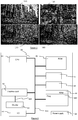
  • Figure 1 illustrates an exemplary embodiment of the method of the present disclosure.
  • the style of at least a part of a visual object (like the image 120), used as a style exemplar (or style reference), is transferred to at least a part of an input visual object (like the image 110) in order to get at least an output visual object (like the image 130 or 140) having at least one part with the geometry of the part 110 of the input visual object but with the style of the part 120 of the style visual object.
  • at least some embodiments of the present disclosure can permit to obtain the style of a visual object having a more or less photorealistic aspect.
  • the look of the intended output can be tailored at run time. For instance, in the exemplary illustration of figure 1 , it can be possible to obtain an image that looks more or less like a painting (as the image 130 of figure 1 ) or like a photography (as the image 140 of figure 1 ).
  • the architecture can be modified at run time in response to one or more user request(s) to permit a user to obtain a resulting output more adapted to his intent (like achieving some artistic or photorealistic result).
  • At least some embodiments of the present disclosure provide a fast solution, compatible with some pseudo-real time implementations where the processing time can be considered as acceptable by a user, for instance a processing time of only a few minutes.
  • the processing time can be considered as acceptable by a user, for instance a processing time of only a few minutes.
  • Some embodiments of the present disclosure that comprises a rendering of the stylized part output at each iteration can further gradually guide the user towards an intended result.
  • some embodiments can allow to modulate the intensity of the style transfer, or in other word modulate the effect, on the resulting output of the style transfer, of at least one style parameter, and to alter another dynamic of the stylized part of the output visual object.
  • Figure 6 describes the structure of an electronic device 60 configured notably to perform any of the embodiments of the method of the present disclosure.
  • the electronic device can be any image and/or video content acquiring device, like a smart phone or a camera. It can also be a device without any video acquiring capabilities but with video processing capabilities.
  • the electronic device 60 can include different devices, linked together via a data and address bus 600, which can also carry a timer signal.
  • a micro-processor 61 or CPU
  • ROM or « Read Only Memory »
  • RAM or « Random Access Memory »
  • the power supply 69 is external to the electronic device 60.
  • the electronic device can also comprise at least one Input/ Output module 64 (including for instance a keyboard, a mouse, a led, and so on) notably adapted to acquire user request(s).
  • the electronic device 60 can include at least one communication interface configured for the reception and/or transmission of data (notably video data), like a receiving interface adapted to receive a style visual object and/or input visual object (like a video and/or an image content) and/or to receive parameters of the deep neural network used according to the present disclosure.
  • the electronic device 60 can communicate with a server (for instance a provider of a bank of style visual objects, or a provider of the deep neural network parameters) thanks to its communication interface(s).
  • the at least one communication interface can comprise at least one communication wireless interface 67 (notably of type WIFI® or Bluetooth®), and/or at least one wired communication interface 68.
  • This one or more communication interface(s) is optional. Indeed, in some embodiments, the electronic device can process style visual object and/or input visual objects stored in a medium readable by the electronic device and/or acquired by the electronic device.
  • the electronic device 60 can also include, or be connected to, a display module 63, for instance a screen.
  • the display can be directly connected to a graphics card 62 by a dedicated bus 620.
  • Such a graphics card may be optional, notably in embodiments where the output of the style transfer is transmitted to another device (for being rendered by a third device for instance).
  • the display module can be used for instance in order to output (either graphically, or textually) information, like an echo or an acknowledgment of a user request, and/or to render at least a part of an input, style and/or output visual object as described hereinafter in connection with the method 500 of the present disclosure.
  • Each of the mentioned memories can include at least one register, that is to say a memory zone of low capacity (a few binary data) or high capacity (with a capability of storage of an entire audio and/or video file notably).
  • the microprocessor 61 loads the program instructions 660 in a register of the RAM 66, notably the program instruction needed for performing at least one embodiment of the method described herein and executes the program instructions.
  • the electronic device 60 includes several microprocessors.
  • microprocessor 61 can be configured for:
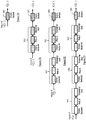
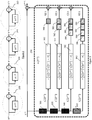
  • Figure 2 illustrates a global structure (or architecture) of a deep neural network for fast style transfer used in at least one exemplary embodiment of the present disclosure.
  • the network can comprise a stack of N sub-networks (with N being a strictly positive integer).
  • the network can comprise less than 10 sub-networks (like 4 sub-networks 200, 220, 240, 260 as illustrated by Figure 2 ).
  • At least some of the sub-networks can have identical structures.
  • all the sub-networks 200, 220, 240, 260 of figure 2 have identical structures (detailed in figures 3 , 4 and 7A to 7D ).
  • the gradient g t (.) of each sub-network is learned prior to the transfer of a style to at least a part of an input visual object.
  • X (t) is thus the input of the sub-network t and X (t + 1) is the output of the sub-network t and also, except for last sub-network (in other words, with the above notation, the sub-network N) , the input of the sub-network (t + 1) ;
  • Figure 3 illustrates the overall structure of a sub-network, and the details of the gradient g t (.) when applied to the image X (t) .
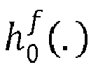
  • the image X (t) is processed by several forward maps h 0 f . , h 1 f . , h 2 f . , h 3 f . of different levels (or in other words scales) to obtain feature maps.
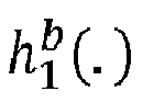
  • a pseudo gradient 302, 322, 342, 362 is then applied to the output of each forward map. At least one backward map h 0 b . , h 1 b . , h 2 b . , h 3 b .
  • the output of the backward maps can be recombined (for instance summed) and subtracted from the image X (t) for obtaining an output image X (t + 1) .
  • the forward map h 0 f . is modelled by element 300 in Figure 4 .
  • the forward map h 0 f . takes as input the image X and output h 0 f X after the going through reference 300.
  • the forward map h 1 f . is modelled by the composition of elements 300 and 320 in Figure 4 : it takes as input the image X and output h 1 f X after the going successively through element 300 and element 320.
  • the forward map h 2 f . is modelled by the composition of 300, 320 and 340 and the forward map h 3 f . is modelled by the composition of 300, 320, 340 and 360.
  • the backward map h 0 b . is modelled by element 380 in Figure 5 .
  • the backward map h 1 b . is modelled by the composition of element 382 and element 380 in Figure 5 : the input of the backward map h 1 b . goes successively through element 382 and element 380.
  • the backward map h 2 b . is modelled by the composition of element 384, element 382 and element 380: the input of this map goes successively through element 384 first, element 382, and element 380.
  • the backward map h 3 b . is modelled similarly by the composition of element 386, element 384, element 382 and element 380.
  • the spatial dimension of the feature maps output by the forward and backward maps vary during the processing.
  • the spatial dimension of the feature maps decreases from element 300 to element 320, from element 320 to element 340, and from element 340 to element 360.
  • the spatial dimension of the feature maps stays constant between element 300 and element 380, between element 320 and element 382, between element 340 and element 384, and between element 360 and element 386.
  • the spatial dimension of the feature maps increases from element 386 to element 384, from element 384 to element 382, and from element 382 to element 380.
  • the forward and backward maps can differ upon iterations.
  • all the parameters, or in other terms the "filters”, of each gradient g t (.) are learned during a learning phase.
  • Figures 4 and figures 7A to 7D illustrate respectively more precisely the structure of the forward maps and the backward maps (and of the corresponding elements 300, 320, 340, 360, 380, 382, 384, 386 of the subnetworks, which can be combined as explained above for obtaining the forward maps and the backward maps).
  • figure 4 shows the different stages (or in other terms "sub-levels") of each forward map.
  • Each element 300, 320, 340 and 360 can comprise at least one convolutional stage, at least one Rectified Linear Unit (ReLU) stage where a non-linear function is applied, and (except for element 300 that corresponds to the first forward map h 0 f . at least one pooling stage.
  • ReLU Rectified Linear Unit
  • element 300 all color channels of the image X (t) are input to a convolutional stage (where a convolution is applied by at least one filter, resulting in feature maps), followed by a ReLU stage where all feature maps having a negative value are forced to zero.
  • the output of element 300 (or in other terms the output of the forward map h 0 f . is then used as the input of a pooling stage of the following element 320, the output of the following element 320 constituting the output of the following forward map h 1 b . . Then the processing continues as shown by figure 4 .
  • the output of the current forward map h 1 b . , h 2 f . being used as the input of a pooling stage of the following element 340, 360, which output constitutes the output of the following forward map h 2 f . , h 3 f . .
  • each forward map h 0 f . , h 1 b . , h 2 f . , h 3 f . . (or in other words the output of elements 300, 320, 340, 360) is used by the pseudo gradient of the corresponding level, while being further used, as explained above, as the input of the following forward map (or in other words the forward map of the next level) except of course for the last forward map , h 3 f . .
  • each convolutional stage increases the number of feature maps while each pooling stage decreases the spatial dimension of the feature maps.
  • each convolutional stage can multiply per 2 the number of feature maps while each pooling stage can divide per 2 the spatial dimension of the feature maps.
  • a filter can have a 3x3 spatial dimension per channel. 16 filters are used in the convolutional stage of the first (or "level 0") forward map 300, 32 filters are used in the convolutional stage of the "level 1" forward map 320, 64 filters are used in the convolutional stage of the "level 2" forward map 340 and 128 filters are used in the convolutional stage of the "level 3" forward map 360.
  • figures 7A to 7D show the structure of the backward maps map h 0 b . , h 1 b . , h 2 b . , h 3 b . and corresponding elements 380, 382, 384, and 386.
  • Each element 382, 384, 386, other than the last element 380 comprises a convolutional stage, a ReLU stage, and an up-sampling stage (noted as "Upsamp" in the figures).
  • the last element 380 only comprises a convolutional stage.
  • a linear interpolation function is applied to at least some of the feature maps to increase the spatial dimension of the feature maps.
  • the structure of the backward maps is symmetrical to the structure of the forward maps.
  • each convolutional stage divides per 2 the number of feature maps while each up-sampling stage multiplies per 2 the spatial dimension of the feature map.
  • the number of elements 386, 384, 382, and 380 successively applied is function of the considered level, the output of an element 386, 384, 382 being used as the input of the next applied element 384, 382, and 380 (if any) for a same level. More precisely, in the exemplary embodiment illustrated, the output of the "level 0" pseudo gradient is directly processed by element 380 (which constitutes the backward map 380).
  • Two elements 382, 380 are successively applied for the output of the "level 1" pseudo gradient, while three elements 384, 382, 380 are successively applied for the output of the "level 2" pseudo gradient and four elements 386, 384, 382, 380 are successively applied for the output of the "level 3" pseudo gradient.
  • the image X (t + 1) can then be obtained by the difference between the image X (t) and the combination of the outputs of all the backward maps.
  • the combination can correspond to an addition or, more generally, to a linear combination.
  • the image X (t + 1) is then used as the input of the next sub-network t + 1.
  • Figure 5 illustrates an exemplary embodiment of the method 500 of the present disclosure.
  • the method comprises obtaining 510 at least a part of at least one visual object (called hereinafter "style visual object") whose style is to be used later as an exemplar (or reference style) for performing a style transfer on at least a part of some input visual object.
  • style visual object can be an image (for instance a still image or an image being part of a video) or can be a part of such an image.
  • the method 500 can comprise obtaining 520 values of the parameters of the learned gradients g t (.) of the sub-networks.
  • the obtaining 520 can comprise learning 524 at least some of the gradients parameters (or transition parameters).
  • the method can also comprise obtaining data needed for the learning and notably obtaining 522 at least a part of at least one training input visual object.
  • at least some of the obtained parts of training visual objects and at least some of the obtained parts of style visual objects are used for performing style transfers, each style transfer having as input one image, or image part, of an obtained training input visual object, and outputting an image, or image part, having the style of at least one image, or at least one image part, of an obtained style visual object, while preserving the content of the part of the training input visual object.
  • the learning can notably involve unrolling 532 (or in other terms "unfolding") the sub-networks from a gradient descent algorithm.
  • the style transfer during the learning can notably be performed (as taught by Gatys et al. for instance), by solving a style transfer problem, based on a minimization of a loss function built using feature maps of the image, or image part, of the training input visual object and style visual object, used respectively as input and style examples, the feature maps being obtained from a pre-trained deep neural network.
  • the parameters of the learned gradient are then obtained by stochastic gradient descent using the above loss function.
  • the stochastic gradients relate to the parameters of the learned gradients (and thus of the sub-networks).
  • the learned gradients replace the gradients in the original descent algorithm for minimization of the above loss function and, is learned so as to solve the style transfer problem in a small number of iterations. While in some embodiments the gradients parameters can be learned (as explained above), in other embodiments, at least some of the learned gradients parameters can be obtained from a storage medium (like a removable storage medium) and/or from a communication interface.
  • the learning phase can be very long and thus can be performed prior to the execution of an application implementing the method of the present disclosure. Furthermore, it can be performed in a device having greater capabilities (in terms on memory and processing notably) than the electronic device where the application is executing.
  • some of the gradient parameters can be learned while some other gradients parameters can be obtained from a storage medium designated by means of a user interface for instance.
  • the method can further comprise using the obtained gradients parameters (or transition parameters) for defining 530 the stack of sub-networks and the corresponding transforms.
  • the method can comprise obtaining 540 an input visual object on which the style transfer is to be performed and obtaining 550 a designation of at least one of the style visual objects used for the learning. It is to be pointed out that the gradients parameters are tailored during the learning according to the style visual objects used for the learning. Thus, the defined stack of sub-networks used at run time for the style transfer is also only adapted to transfer (to an input visual object) the style of one the style visual objects used during the learning.
  • the obtaining 550 of a designation can comprise rendering at least one image, or image part, of at least one of the obtained style visual objects on a user interface of the electronic device 60 and acquiring the designation from the user interface.
  • the method can comprise performing 560 a style transfer on the obtained input image, by using the matrix H s corresponding to the designated part of the obtained style visual object s and the learned gradient parameters for the stack of sub-networks.
  • the network can be modified by taking into account at least one other parameter, before applying the style transfer. Indeed, in the illustrated embodiment, at least one parameter of the style transfer can be tailored at run time via the user interface.
  • the filter i ( L ) can be applied on the combination of the outputs of the backward maps.
  • the filter can be included in at least one of the backward and/or forward maps of at least one of the levels.
  • many variants can be considered for including the filter in one or more backward and/or forward map(s).
  • the filter can be applied after a convolution layer.
  • Figures 8A to 8D illustrate another example including, for each level, a filter 800 after the last element 380 of each backward map.
  • filter can be included after each convolution layer of each forward and backward map.
  • the gradients can be modified for altering some intrinsic property in the output image.
  • the intrinsic property can be a property that has not been used by an optimization function used for obtaining the sub-networks 200, 220, 240, 260 while being however derivable from an optimization function.
  • Such an intrinsic property can be a pixel dynamic of at least a part of one or more reference visual object(s), like the part of the input visual object on which the style transfer applied, the designated style reference image and/or a third image (like another part of one of the obtained style visual object, or an image designated via the user interface).
  • the pixel dynamic can be a limitation of the possible range(s) of values of pixels in the output of the style transfer.
  • the pixel dynamic can impact a photorealistic effect of the output of the style transfer (that can be made more or less photorealistic by modifying the gradients), as illustrated by figure 1 .
  • the pixel dynamic can also impact the possible colors of a pixel of at least a part of in the output visual object.
  • the part of the output visual object can comprise only a limited set of colors, (like only grey levels) compared to the part of the input visual object).
  • the pixel dynamic can also impact a preserving, inside the part of the output visual object, of the local contrasts inside the part of the input visual object.
  • the at least one other parameter can be obtained thanks to a cost function representative of the image intrinsic property. For instance, it can be obtained by minimizing a cost function.
  • This cost function can be selected, amongst several cost functions, thanks to the user interface. For instance, a sentence can be output on a user interface in order to obtain, in response, a choice of a user between several proposals. The response obtained from the user interface can permit to determine the cost function to use. For instance, when performing a style transfer on an input image, a question like "Do you want a more photorealistic rendering of the output image? (For "Yes", press button A, for "No” press button B”) can be output. Depending on the pressed button, the cost function selected can differ, thus permitting to output a more or less photorealistic image.
  • At least some embodiments of the present disclosure can permit to vary the style transfer intensity. In other word, it can be possible to modulate the impact on the style of the part of the reference visual object on the part of the output visual object.
  • the intensity of the style transfer can be controlled at runtime (notably via a user interface) by multiplying the gradient g t ( X ( t ) ) by a parameter ⁇ .
  • X t + 1 X t ⁇ ⁇ g t X t With ⁇ being a real number with a positive value.
  • the parameter ⁇ can be defined differently.
  • the parameter ⁇ can be defined as a vector ⁇ ( ⁇ i ) .
  • each h i b . represents the output of a scale (or level) of the gradient
  • the method can comprise obtaining 562 at least one user input and modifying the gradient consequently and thus modifying 564 the transforms, as explained above. For instance, a user input relating to a variation of a photorealistic effect, or a weighting of one or more scales (or levels) can be obtained.
  • the method can comprise 566 applying the modified transforms with the modified gradients to at least a part of the input visual object.
  • the method can comprise rendering 568, at least partially, at least one output visual object comprising at least one image, or image part, being the output of the style transfer applied to the at least one image, or image part, of the input visual object.
  • the rendering 568 can comprise a rendering of the part (on which the style transfer is applied) of input visual object, a rendering of the part of the style visual object used as a reference style, and/or a rendering of the stylized image or image part.
  • the rendering can comprise displaying at least one of the above information on a display on the device where the method of the present disclosure is performed, or printing at least one of the above information, and/or storing at least one of the above information on a specific support. This rendering is optional.
  • a variant of the style transfer method detailed above is presented hereinafter.
  • This matching can be achieved by using a mask, that can be represented by a diagonal matrix M , that identifies a part of the image.
  • the mask contains first values ("1" for instance) on the region of interest and second values (like null values) everywhere else.
  • the filters that adjust the style in the network i.e., h i f X t T h i f X t ⁇ H i , t s (with link to Figure 3 ), can be modified as follows with the mask: 1 Tr M i M i h i f X t T M i h i f X t ⁇ H i , t s , where Tr ( M i ) is the trace of matrix M i , i.e., the sum of its diagonal entries.
  • Such an embodiment can permit to take into account only the region of interest of the input image to adjust the style, instead of taking into account the full input image. as in some other embodiments described earlier,
  • the matrix M i is the matrix M that is adapted to the spatial resolution of the feature maps at the i th level (for example by down-sampling the content image X (0) at the spatial resolution of i th level and finding the region of interest in this down-sampled image to create the mask M i ).
  • the disclosure notably relates to a method comprising:
  • the disclosure also relates to an electronic device comprising at least one memory and one or several processors configured for collectively:
  • the present disclosure relates to an electronic device comprising at least one memory and at least one processing circuitry configured for:
  • each of successive transform is a sub-network of a deep neural network.
  • the cost function is selectable from a user interface.
  • obtaining transition parameters comprises learning the transition parameters by minimizing a training loss function from feature maps of at least one training pair of images, each training pair comprising a training input visual object and one of the style visual objects.
  • the architecture of the successive transforms is obtained by unrolling a gradient descent algorithm.
  • the feature maps are computed by using a pre-trained deep neural network.
  • the modifying is performed at run time.
  • the modifying is performed in response to a first user request.
  • the at least one other parameter is weighted according to the first user request.
  • the intrinsic property is a dynamic of a reference visual object.
  • the intrinsic property relates to at least one of:
  • the method comprises weighting parameters of at least one of the transforms.
  • the weighting is performed at run time.
  • the weighting is performed in response to a second user request.
  • the electronic device of the present disclosure can be adapted to perform the method of the present disclosure in any of its embodiments.
  • the present disclosure relates to a communication system comprising an electronic device of the present disclosure in any of its embodiments.
  • the present disclosure relates to a non-transitory program storage device, readable by a computer.
  • the non-transitory computer readable program storage device tangibly embodies a program of instructions executable by a computer to perform the method of the present disclosure in any of its embodiments.
  • the present disclosure relates to a non-transitory program storage product, readable by a computer.
  • the non-transitory computer readable program product tangibly embodies program code instructions for performing, when the non-transitory software program is executed by a computer, the method of the present disclosure in any of its embodiments.
  • At least one embodiment of the present disclosure relates to a non-transitory computer readable program product comprising program code instructions for performing, when the non-transitory software program is executed by a computer, a method comprising:
  • the present disclosure relates to a computer readable storage medium carrying a software program comprising program code instructions for performing the method of the present disclosure, in any of its embodiments, when the software program is executed by a computer.
  • the computer readable storage medium tangibly embodies a program of instructions executable by a computer for performing, when the non-transitory software program is executed by a computer, a method comprising:
  • the computer readable storage medium carries a software program comprising program code instructions, when the non-transitory software program is executed by a computer, a method comprising:
  • aspects of the present principles can be embodied as a system, method, or computer readable medium. Accordingly, aspects of the present disclosure can take the form of a hardware embodiment, a software embodiment (including firmware, resident software, micro-code, and so forth), or an embodiment combining software and hardware aspects that can all generally be referred to herein as a "circuit", module" or "system”. Furthermore, aspects of the present principles can take the form of a computer readable storage medium. Any combination of one or more computer readable storage medium(s) may be utilized.
  • a computer readable storage medium can take the form of a computer readable program product embodied in one or more computer readable medium(s) and having computer readable program code embodied thereon that is executable by a computer.
  • a computer readable storage medium as used herein is considered a non-transitory storage medium given the inherent capability to store the information therein as well as the inherent capability to provide retrieval of the information therefrom.
  • a computer readable storage medium can be, for example, but is not limited to, an electronic, magnetic, optical, electromagnetic, infrared, or semiconductor system, apparatus, or device, or any suitable combination of the foregoing.
  • At least some embodiment of the style transfer method of the present disclosure can be applied in a consumer context, for instance for providing a new tool for image editing, more powerful than just color transfer, and more powerful than tools like Instagram® where image filters are defined once and for all.
  • At least some embodiment of the style transfer method of the present disclosure can be applied in a (semi)-professional context, for instance for providing a tool to be used to perform image manipulation and editing in an interactive manner, like for pre-editing or pre-grading before a manual intervention.
Landscapes

  • Physics & Mathematics (AREA)
  • General Physics & Mathematics (AREA)
  • Engineering & Computer Science (AREA)
  • Theoretical Computer Science (AREA)
  • Image Analysis (AREA)
  • Image Processing (AREA)

Abstract

The disclosure relates to a method comprising:- obtaining transition parameters of at least one transform of a plurality of successive transforms, the output of a transform being used as the input of the following transform, at least one of the transition parameters encoding style characteristics of at least a part of a first visual object of a plurality of style visual objects;- modifying the successive transforms by taking account of at least one other parameter derived from a cost function representative of an image intrinsic property;- obtaining an output image from a part of an input visual object by applying successively the modified transforms, the part of the input visual object being used as the input of the first of the transforms. The disclosure also relates to corresponding electronic device, computer readable program product and computer readable storage medium.

Description

    1. Technical field
  • The present disclosure relates to transfer of a style of at least a part of an exemplar visual object to at least a part of another visual object. For example, a visual object can correspond to an image, a part of an image, a video and/or a part of a video.
  • A method for transfer of a style of at least a part of an exemplar visual object to at least a part of another visual object, and corresponding electronic device, computer readable program products and computer readable storage medium are described.
  • 2. Background art
  • Style transfer is the task of transforming at least a part of a first visual object (like a first image) in such a way that it resembles the style of at least a part of another visual object (like a second image) used as an example, while preserving the content of the part of the first visual object. This class of computational methods are of special interest in film post-production and graphics, where one could generate different renditions of the same scene under different "style parameters". Here, we see the style of an image (or a part of an image) as a composition of different visual attributes such as color, shading, texture, lines, strokes and regions.
  • Style transfer is closely related to non-parametric texture synthesis and transfer. Texture transfer can be seen as a special case of texture synthesis, in which example-based texture generation is constrained by the geometry of an original image. Style transfer, for this part, can be considered as a texture transfer, where one searches to transfer style from an example to an original image, and style is essentially modeled as a texture.
  • Some known style transfer solutions using deep neural networks have led to visually impressive results. For instance, Gatys et al. (Gatys L., Ecker A., & Bethge M. "Image style transfer using convolutional neural networks." CVPR 2016) have proposed to perform style transfer by minimization of a loss function built using feature maps obtained from a pre-trained deep neural network. However, while yielding good results, this method is nevertheless slow as the stylized image output by the method is a solution of a long iterative optimization problem.
  • Furthermore, the above method is not adapted to a transfer of a style of a natural image (or in other word a photography).
  • Thus, researchers have looked for a solution that will overcome those issues. However, all known methods are either very slow, or not adapted to give a photographic style to an image.
    So, there is need for a solution that can help enhancing the user experience of a style transfer application.
  • 3. Summary
  • The present principles enable at least one of the above disadvantages to be resolved by proposing a method comprising:
    • obtaining transition parameters of at least one transform of a plurality of successive transforms, the output of a transform being used as the input of the following transform, at least one of said transition parameters encoding style characteristics of at least a part of a first visual object of a plurality of style visual objects;
    • modifying said successive transforms by taking account of at least one other parameter derived from a cost function representative of an image intrinsic property;
    • obtaining an output image from a part of an input visual object by applying successively said modified transforms, said part of said input visual object being used as the input of the first of said transforms.
  • At least one embodiment of the present disclosure can propose a solution for transferring a style of at least a part of an example visual object, such as an image, a part of an image, a video or a part of a video, to at least a part of an input visual object, in a way helping to capture a style of the part of the exemplar visual object while helping preserving the structure of the part of the input visual object.
  • According to another aspect, the present disclosure relates to an electronic device comprising at least one memory and one or several processors configured for collectively transferring the style of a reference visual object to an input visual object.
  • According to at least one embodiment of the present disclosure, said one or several processors are configured for collectively:
    • obtaining transition parameters of at least one transform of a plurality of successive transforms, the output of a transform being used as the input of the following transform, at least one of said transition parameters encoding style characteristics of at least a part of a first visual object of a plurality of style visual objects;
    • modifying said successive transforms by taking account of at least one other parameter derived from a cost function representative of an image intrinsic property;
    • obtaining an output image from a part of an input visual object by applying successively said modified transforms, said part of said input visual object being used as the input of the first of said transforms.
    4. List of drawings.
  • The present disclosure will be better understood, and other specific features and advantages will emerge upon reading the following description, the description referring to the annexed drawings wherein:
    • Figure 1 illustrates an input image, a style reference image (or in other word a style exemplar image) and two different resulting output images that can be obtained at run time according to at least one exemplary embodiment of the present disclosure;
    • Figure 2 illustrates a global structure of a deep neural network for fast style transfer used in at least one exemplary embodiment of the present disclosure;
    • Figure 3 illustrates a structure of one iteration of the deep neural network for fast style transfer according to at least one exemplary embodiment of the present disclosure;
    • Figure 4 illustrates a structure of the forward maps of one iteration of the deep neural network for fast style transfer according to at least one exemplary embodiment of the present disclosure;
    • Figure 5 is a functional diagram that illustrates an exemplary embodiment of the method of the present disclosure;
    • Figure 6 illustrates an electronic device according to at least one exemplary embodiment of the present disclosure;
    • Figures 7A to 7D illustrate a structure of the backward maps of one iteration of the deep neural network for fast style transfer according to at least one exemplary embodiment of the present disclosure;
    • Figure 8A to 8D illustrate a structure of the backward maps, with a structure preserving filter, of one iteration of the deep neural network for fast style transfer according to at least one exemplary embodiment of the present disclosure.
  • It is to be noted that the drawings have only an illustration purpose and that the embodiments of the present disclosure are not limited to the illustrated embodiments.
  • 5. Detailed description of the embodiments.
  • At least some principles of the present disclosure propose a new and flexible neural network architecture that can be used to perform fast style transfer.
  • Figure 1 illustrates an exemplary embodiment of the method of the present disclosure.
  • The style of at least a part of a visual object (like the image 120), used as a style exemplar (or style reference), is transferred to at least a part of an input visual object (like the image 110) in order to get at least an output visual object (like the image 130 or 140) having at least one part with the geometry of the part 110 of the input visual object but with the style of the part 120 of the style visual object. Notably, at least some embodiments of the present disclosure can permit to obtain the style of a visual object having a more or less photorealistic aspect.
  • Furthermore, in some embodiments of the method of the present disclosure, the look of the intended output can be tailored at run time. For instance, in the exemplary illustration of figure 1, it can be possible to obtain an image that looks more or less like a painting (as the image 130 of figure 1) or like a photography (as the image 140 of figure 1).
  • The possibility to modify the look of the stylized part of the output visual object at run time can be provided thanks to the flexibility of a deep neural network architecture used according to the present disclosure.
  • For instance, the architecture can be modified at run time in response to one or more user request(s) to permit a user to obtain a resulting output more adapted to his intent (like achieving some artistic or photorealistic result).
  • At least some embodiments of the present disclosure provide a fast solution, compatible with some pseudo-real time implementations where the processing time can be considered as acceptable by a user, for instance a processing time of only a few minutes. Thus, it can be possible for a user to iterate several times the style transfer on a same part of an input visual object, with modified architectures, until he gets satisfied by the resulting output. Some embodiments of the present disclosure that comprises a rendering of the stylized part output at each iteration can further gradually guide the user towards an intended result.
  • Notably, some embodiments can allow to modulate the intensity of the style transfer, or in other word modulate the effect, on the resulting output of the style transfer, of at least one style parameter, and to alter another dynamic of the stylized part of the output visual object.
  • Figure 6 describes the structure of an electronic device 60 configured notably to perform any of the embodiments of the method of the present disclosure.
  • The electronic device can be any image and/or video content acquiring device, like a smart phone or a camera. It can also be a device without any video acquiring capabilities but with video processing capabilities.
  • In the exemplary embodiment of figure 6, the electronic device 60 can include different devices, linked together via a data and address bus 600, which can also carry a timer signal. For instance, it can include a micro-processor 61 (or CPU), a ROM (or « Read Only Memory ») 65, a RAM (or « Random Access Memory ») 66, a power supply 69. According to another variant, the power supply 69 is external to the electronic device 60.
  • In the exemplary embodiment of figure 6, the electronic device can also comprise at least one Input/ Output module 64 (including for instance a keyboard, a mouse, a led, and so on) notably adapted to acquire user request(s). The electronic device 60 can include at least one communication interface configured for the reception and/or transmission of data (notably video data), like a receiving interface adapted to receive a style visual object and/or input visual object (like a video and/or an image content) and/or to receive parameters of the deep neural network used according to the present disclosure. For instance, the electronic device 60 can communicate with a server (for instance a provider of a bank of style visual objects, or a provider of the deep neural network parameters) thanks to its communication interface(s).
  • The at least one communication interface can comprise at least one communication wireless interface 67 (notably of type WIFI® or Bluetooth®), and/or at least one wired communication interface 68.
  • This one or more communication interface(s) is optional. Indeed, in some embodiments, the electronic device can process style visual object and/or input visual objects stored in a medium readable by the electronic device and/or acquired by the electronic device.
  • In some embodiments, the electronic device 60 can also include, or be connected to, a display module 63, for instance a screen. The display can be directly connected to a graphics card 62 by a dedicated bus 620. Such a graphics card may be optional, notably in embodiments where the output of the style transfer is transmitted to another device (for being rendered by a third device for instance). The display module can be used for instance in order to output (either graphically, or textually) information, like an echo or an acknowledgment of a user request, and/or to render at least a part of an input, style and/or output visual object as described hereinafter in connection with the method 500 of the present disclosure.
  • Each of the mentioned memories can include at least one register, that is to say a memory zone of low capacity (a few binary data) or high capacity (with a capability of storage of an entire audio and/or video file notably).
  • When the electronic device 60 is powered on, the microprocessor 61 loads the program instructions 660 in a register of the RAM 66, notably the program instruction needed for performing at least one embodiment of the method described herein and executes the program instructions.
  • According to a variant, the electronic device 60 includes several microprocessors.
  • In the exemplary embodiment illustrated in figure 6, the microprocessor 61 can be configured for:
    • obtaining transition parameters of at least one transform of a plurality of successive transforms, the output of a transform being used as the input of the following transform, at least one of the transition parameters encoding style characteristics of at least a part of a first visual object of a plurality of style visual objects;
    • modifying the successive transforms by taking account of at least one other parameter derived from a cost function representative of an image intrinsic property;
    • obtaining an output image from a part of an input visual object by applying successively the modified transforms, the part of the input visual object being used as the input of the first of the transforms.
  • Figure 2 illustrates a global structure (or architecture) of a deep neural network for fast style transfer used in at least one exemplary embodiment of the present disclosure.
  • In the detailed embodiment, the network can comprise a stack of N sub-networks (with N being a strictly positive integer). For instance, the network can comprise less than 10 sub-networks (like 4 sub-networks 200, 220, 240, 260 as illustrated by Figure 2).
  • At least some of the sub-networks can have identical structures. For instance, in the exemplary embodiment of figures 2, 3, 4, 7A to 7D, all the sub-networks 200, 220, 240, 260 of figure 2 have identical structures (detailed in figures 3, 4 and 7A to 7D).
  • Each sub-network t (with t in the range [1; N]) transforms, at pixel levels, the image X(t) of a visual object into a new image X(t+1) through one step of learned gradient given with the below formula: X t + 1 = X t g t X t
    Figure imgb0001
    With gt (.) being a learned gradient of the sub-network t.
  • Indeed, as it will be explained later, the gradient gt (.) of each sub-network is learned prior to the transfer of a style to at least a part of an input visual object.
  • With this notation, X(t) is thus the input of the sub-network t and X (t+1) is the output of the sub-network t and also, except for last sub-network (in other words, with the above notation, the sub-network N), the input of the sub-network (t+1);
  • The structure of a sub-network t is presented hereinafter in connection with figures 3, 4 and 7A to 7D.
  • Figure 3 illustrates the overall structure of a sub-network, and the details of the gradient gt (.) when applied to the image X(t). As shown by figure 3, the image X(t) is processed by several forward maps h 0 f . ,
    Figure imgb0002
    h 1 f . ,
    Figure imgb0003
    h 2 f . ,
    Figure imgb0004
    h 3 f .
    Figure imgb0005
    of different levels (or in other words scales) to obtain feature maps. A pseudo gradient 302, 322, 342, 362 is then applied to the output of each forward map. At least one backward map h 0 b . ,
    Figure imgb0006
    h 1 b . ,
    Figure imgb0007
    h 2 b . ,
    Figure imgb0008
    h 3 b .
    Figure imgb0009
    is used for processing each output of the pseudo gradients 302, 322, 342, 362. The output of the backward maps can be recombined (for instance summed) and subtracted from the image X(t) for obtaining an output image X (t+1) .
  • The forward map h 0 f .
    Figure imgb0010
    is modelled by element 300 in Figure 4. The forward map h 0 f .
    Figure imgb0011
    takes as input the image X and output h 0 f X
    Figure imgb0012
    after the going through reference 300. The forward map h 1 f .
    Figure imgb0013
    is modelled by the composition of elements 300 and 320 in Figure 4: it takes as input the image X and output h 1 f X
    Figure imgb0014
    after the going successively through element 300 and element 320. Similarly, the forward map h 2 f .
    Figure imgb0015
    is modelled by the composition of 300, 320 and 340 and the forward map h 3 f .
    Figure imgb0016
    is modelled by the composition of 300, 320, 340 and 360.
  • The backward map h 0 b .
    Figure imgb0017
    is modelled by element 380 in Figure 5. The backward map h 1 b .
    Figure imgb0018
    is modelled by the composition of element 382 and element 380 in Figure 5: the input of the backward map h 1 b .
    Figure imgb0019
    goes successively through element 382 and element 380. Similarly, the backward map h 2 b .
    Figure imgb0020
    is modelled by the composition of element 384, element 382 and element 380: the input of this map goes successively through element 384 first, element 382, and element 380. Finally, the backward map h 3 b .
    Figure imgb0021
    is modelled similarly by the composition of element 386, element 384, element 382 and element 380.
  • The spatial dimension of the feature maps output by the forward and backward maps vary during the processing. Notably, according to figure 3, the spatial dimension of the feature maps decreases from element 300 to element 320, from element 320 to element 340, and from element 340 to element 360. The spatial dimension of the feature maps stays constant between element 300 and element 380, between element 320 and element 382, between element 340 and element 384, and between element 360 and element 386. The spatial dimension of the feature maps increases from element 386 to element 384, from element 384 to element 382, and from element 382 to element 380.
  • The matrix H i , t s ,
    Figure imgb0022
    i = 0,···,3, t = 0,···,3, used by the pseudo gradient 302, 322, 342, 362 of each level, encodes the style of at least a part of an exemplar visual object s.
  • In the exemplary embodiment illustrated, each sub-network has the same structure, and the forward and backward maps are the same for each sub-network t = 0,···,3. However, the matrixes H i , t s ,
    Figure imgb0023
    i = 0,···,3, t = 0,···, 3 can be different between the sub-networks. Of course, in other embodiments where the structure of at least some of the sub-networks can be different, the forward and backward maps can differ upon iterations.
  • As it will be explained with more details later, in the exemplary embodiment of figure 3, all the parameters, or in other terms the "filters", of each gradient gt (.) are learned during a learning phase. The learned parameters include notably all filters of the forward and backward maps, as well as the matrixes H i , t s ,
    Figure imgb0024
    i = 0,···,3, t = 0,···, 3 for each style exemplar visual object s. Those parameters are called hereinafter "gradients parameters" or "transition parameters".
  • Figures 4 and figures 7A to 7D illustrate respectively more precisely the structure of the forward maps and the backward maps (and of the corresponding elements 300, 320, 340, 360, 380, 382, 384, 386 of the subnetworks, which can be combined as explained above for obtaining the forward maps and the backward maps).
  • Notably, figure 4 shows the different stages (or in other terms "sub-levels") of each forward map. Each element 300, 320, 340 and 360 can comprise at least one convolutional stage, at least one Rectified Linear Unit (ReLU) stage where a non-linear function is applied, and (except for element 300 that corresponds to the first forward map h 0 f .
    Figure imgb0025
    at least one pooling stage. As shown in figure 4, in element 300, all color channels of the image X(t) are input to a convolutional stage (where a convolution is applied by at least one filter, resulting in feature maps), followed by a ReLU stage where all feature maps having a negative value are forced to zero. The output of element 300 (or in other terms the output of the forward map h 0 f .
    Figure imgb0026
    is then used as the input of a pooling stage of the following element 320, the output of the following element 320 constituting the output of the following forward map h 1 b . .
    Figure imgb0027
    Then the processing continues as shown by figure 4. The output of the current forward map h 1 b . ,
    Figure imgb0028
    h 2 f .
    Figure imgb0029
    being used as the input of a pooling stage of the following element 340, 360, which output constitutes the output of the following forward map h 2 f . ,
    Figure imgb0030
    h 3 f . .
    Figure imgb0031
  • The output of each forward map h 0 f . ,
    Figure imgb0032
    h 1 b . ,
    Figure imgb0033
    h 2 f . ,
    Figure imgb0034
    h 3 f . .
    Figure imgb0035
    (or in other words the output of elements 300, 320, 340, 360) is used by the pseudo gradient of the corresponding level, while being further used, as explained above, as the input of the following forward map (or in other words the forward map of the next level) except of course for the last forward map , h 3 f . .
    Figure imgb0036
    In the exemplary embodiment of figure 4, each convolutional stage increases the number of feature maps while each pooling stage decreases the spatial dimension of the feature maps. For instance, each convolutional stage can multiply per 2 the number of feature maps while each pooling stage can divide per 2 the spatial dimension of the feature maps. In the exemplary embodiment of figure 4, a filter can have a 3x3 spatial dimension per channel. 16 filters are used in the convolutional stage of the first (or "level 0") forward map 300, 32 filters are used in the convolutional stage of the "level 1" forward map 320, 64 filters are used in the convolutional stage of the "level 2" forward map 340 and 128 filters are used in the convolutional stage of the "level 3" forward map 360.
  • Similarly, figures 7A to 7D show the structure of the backward maps map h 0 b . ,
    Figure imgb0037
    h 1 b . ,
    Figure imgb0038
    h 2 b . ,
    Figure imgb0039
    h 3 b .
    Figure imgb0040
    and corresponding elements 380, 382, 384, and 386. Each element 382, 384, 386, other than the last element 380 comprises a convolutional stage, a ReLU stage, and an up-sampling stage (noted as "Upsamp" in the figures). The last element 380 only comprises a convolutional stage. During the up-sampling stage, a linear interpolation function is applied to at least some of the feature maps to increase the spatial dimension of the feature maps. The structure of the backward maps is symmetrical to the structure of the forward maps. In the exemplary embodiment of figure 4, each convolutional stage divides per 2 the number of feature maps while each up-sampling stage multiplies per 2 the spatial dimension of the feature map. The number of elements 386, 384, 382, and 380 successively applied is function of the considered level, the output of an element 386, 384, 382 being used as the input of the next applied element 384, 382, and 380 (if any) for a same level. More precisely, in the exemplary embodiment illustrated, the output of the "level 0" pseudo gradient is directly processed by element 380 (which constitutes the backward map 380). Two elements 382, 380 are successively applied for the output of the "level 1" pseudo gradient, while three elements 384, 382, 380 are successively applied for the output of the "level 2" pseudo gradient and four elements 386, 384, 382, 380 are successively applied for the output of the "level 3" pseudo gradient.
  • In the embodiment of figures 7A to 7D, the image X (t+1) can then be obtained by the difference between the image X(t) and the combination of the outputs of all the backward maps. The combination can correspond to an addition or, more generally, to a linear combination. The image X (t+1) is then used as the input of the next sub-network t+1.
  • Figure 5 illustrates an exemplary embodiment of the method 500 of the present disclosure.
  • In the illustrated embodiment, the method comprises obtaining 510 at least a part of at least one visual object (called hereinafter "style visual object") whose style is to be used later as an exemplar (or reference style) for performing a style transfer on at least a part of some input visual object. The style visual object can be an image (for instance a still image or an image being part of a video) or can be a part of such an image.
  • As illustrated by figure 5, the method 500 can comprise obtaining 520 values of the parameters of the learned gradients gt (.) of the sub-networks.
  • In some embodiments, the obtaining 520 can comprise learning 524 at least some of the gradients parameters (or transition parameters). Notably, as illustrated by figure 5, the method can also comprise obtaining data needed for the learning and notably obtaining 522 at least a part of at least one training input visual object. In the exemplary embodiment described, during the learning 524, at least some of the obtained parts of training visual objects and at least some of the obtained parts of style visual objects are used for performing style transfers, each style transfer having as input one image, or image part, of an obtained training input visual object, and outputting an image, or image part, having the style of at least one image, or at least one image part, of an obtained style visual object, while preserving the content of the part of the training input visual object.
  • The learning can notably involve unrolling 532 (or in other terms "unfolding") the sub-networks from a gradient descent algorithm. In the exemplary embodiment illustrated, the style transfer during the learning can notably be performed (as taught by Gatys et al. for instance), by solving a style transfer problem, based on a minimization of a loss function built using feature maps of the image, or image part, of the training input visual object and style visual object, used respectively as input and style examples, the feature maps being obtained from a pre-trained deep neural network.
  • The parameters of the learned gradient are then obtained by stochastic gradient descent using the above loss function. Thus, while the gradient used in the above loss function relates to an input image, the stochastic gradients relate to the parameters of the learned gradients (and thus of the sub-networks). The learned gradients replace the gradients in the original descent algorithm for minimization of the above loss function and, is learned so as to solve the style transfer problem in a small number of iterations. While in some embodiments the gradients parameters can be learned (as explained above), in other embodiments, at least some of the learned gradients parameters can be obtained from a storage medium (like a removable storage medium) and/or from a communication interface. This can be the case for instance when at least some of the gradients parameters have been learned previously, in the electronic device where the method 500 is implemented or in a remote device. Indeed, in some embodiments, the learning phase can be very long and thus can be performed prior to the execution of an application implementing the method of the present disclosure. Furthermore, it can be performed in a device having greater capabilities (in terms on memory and processing notably) than the electronic device where the application is executing.
  • It is to be pointed out that in a variant, some of the gradient parameters can be learned while some other gradients parameters can be obtained from a storage medium designated by means of a user interface for instance.
  • The method can further comprise using the obtained gradients parameters (or transition parameters) for defining 530 the stack of sub-networks and the corresponding transforms.
  • As illustrated by figure 5, the method can comprise obtaining 540 an input visual object on which the style transfer is to be performed and obtaining 550 a designation of at least one of the style visual objects used for the learning. It is to be pointed out that the gradients parameters are tailored during the learning according to the style visual objects used for the learning. Thus, the defined stack of sub-networks used at run time for the style transfer is also only adapted to transfer (to an input visual object) the style of one the style visual objects used during the learning.
  • In some embodiments, the obtaining 550 of a designation can comprise rendering at least one image, or image part, of at least one of the obtained style visual objects on a user interface of the electronic device 60 and acquiring the designation from the user interface.
  • In some embodiments, the method can comprise performing 560 a style transfer on the obtained input image, by using the matrix Hs corresponding to the designated part of the obtained style visual object s and the learned gradient parameters for the stack of sub-networks. In other embodiments, the network can be modified by taking into account at least one other parameter, before applying the style transfer. Indeed, in the illustrated embodiment, at least one parameter of the style transfer can be tailored at run time via the user interface.
  • Notably, to achieve more or less photorealistic results (as illustrated by output image 130 and 140 of figure 1), the network can be modified at runtime as follows: X t + 1 = X t g t X t i L ,
    Figure imgb0041
    where gt (X (t))*i(L) denotes the filtering of the gradient gt (X (t)) with the structure preserving filter i(L).
  • The matrix L can be a matrix like the one known as "the matting Laplacian" described by Levin, Lischinski & Weiss (A Closed-Form Solution to Natural Image Matting, IEEE PAMI, vol. 30(2), pp. 228-242, 2008), and i(.) can be a function having as argument the matrix L, like a polynomial function: i L = j = 1 m α j L j .
    Figure imgb0042
  • Alternatively, the learned gradient gt (.) can be modified as follows: X t + 1 = X t I + γL 1 g t X t ,
    Figure imgb0043
    or: X t + 1 = I + γL 1 X t g t X t
    Figure imgb0044
    where I is the identity matrix and γ > 0 is a tunable parameter.
  • In some embodiments, the filter i(L) can be applied on the combination of the outputs of the backward maps. Alternatively, the filter can be included in at least one of the backward and/or forward maps of at least one of the levels. Of course, many variants can be considered for including the filter in one or more backward and/or forward map(s). For instance, the filter can be applied after a convolution layer. Figures 8A to 8D illustrate another example including, for each level, a filter 800 after the last element 380 of each backward map. According to still another example, filter can be included after each convolution layer of each forward and backward map.
  • In a more general way, the gradients can be modified for altering some intrinsic property in the output image. The intrinsic property can be a property that has not been used by an optimization function used for obtaining the sub-networks 200, 220, 240, 260 while being however derivable from an optimization function. Such an intrinsic property can be a pixel dynamic of at least a part of one or more reference visual object(s), like the part of the input visual object on which the style transfer applied, the designated style reference image and/or a third image (like another part of one of the obtained style visual object, or an image designated via the user interface).
  • The pixel dynamic can be a limitation of the possible range(s) of values of pixels in the output of the style transfer. For instance, the pixel dynamic can impact a photorealistic effect of the output of the style transfer (that can be made more or less photorealistic by modifying the gradients), as illustrated by figure 1. The pixel dynamic can also impact the possible colors of a pixel of at least a part of in the output visual object. For instance, the part of the output visual object can comprise only a limited set of colors, (like only grey levels) compared to the part of the input visual object). The pixel dynamic can also impact a preserving, inside the part of the output visual object, of the local contrasts inside the part of the input visual object.
  • The at least one other parameter can be obtained thanks to a cost function representative of the image intrinsic property. For instance, it can be obtained by minimizing a cost function. This cost function can be selected, amongst several cost functions, thanks to the user interface. For instance, a sentence can be output on a user interface in order to obtain, in response, a choice of a user between several proposals. The response obtained from the user interface can permit to determine the cost function to use. For instance, when performing a style transfer on an input image, a question like "Do you want a more photorealistic rendering of the output image? (For "Yes", press button A, for "No" press button B") can be output. Depending on the pressed button, the cost function selected can differ, thus permitting to output a more or less photorealistic image.
  • It is to be pointed out that with a cost function being always null will result in the obtaining of an "identify"' filter, not altering the transition parameters.
  • Furthermore, at least some embodiments of the present disclosure can permit to vary the style transfer intensity. In other word, it can be possible to modulate the impact on the style of the part of the reference visual object on the part of the output visual object.
  • For instance, in some embodiments, the intensity of the style transfer can be controlled at runtime (notably via a user interface) by multiplying the gradient gt (X (t)) by a parameter β. X t + 1 = X t β g t X t
    Figure imgb0045
    With β being a real number with a positive value.
  • Of course, the parameter β can be defined differently. For instance, the parameter β can be defined as a vector β(βi ).
  • Notably, if the gradient gt (X (t)) is noted as g t . = i = 0 3 h i b .
    Figure imgb0046
    (where each h i b .
    Figure imgb0047
    represents the output of a scale (or level) of the gradient, the gradient can be modified as g t . = i = 0 3 β i h i b . ,
    Figure imgb0048
    in order to weight differently the effect of the style features for at least one scale in the final result.
  • In such embodiments, where the gradient of at least one of the sub-networks can be modified at run time (by weighing at least one parameter relating to a dynamic and/or a style transfer intensity for instance), the method can comprise obtaining 562 at least one user input and modifying the gradient consequently and thus modifying 564 the transforms, as explained above. For instance, a user input relating to a variation of a photorealistic effect, or a weighting of one or more scales (or levels) can be obtained.
  • As illustrated by figure 5, the method can comprise 566 applying the modified transforms with the modified gradients to at least a part of the input visual object. The method can comprise rendering 568, at least partially, at least one output visual object comprising at least one image, or image part, being the output of the style transfer applied to the at least one image, or image part, of the input visual object. Depending upon embodiments, the rendering 568 can comprise a rendering of the part (on which the style transfer is applied) of input visual object, a rendering of the part of the style visual object used as a reference style, and/or a rendering of the stylized image or image part. The rendering can comprise displaying at least one of the above information on a display on the device where the method of the present disclosure is performed, or printing at least one of the above information, and/or storing at least one of the above information on a specific support. This rendering is optional.
  • A variant of the style transfer method detailed above is presented hereinafter. Sometimes one can wish to take into account just a part of an image during the style transformation, e.g., to match parts of an input image and one of the style reference image(s) that have the same semantic (sky to sky, buildings to buildings, roads to roads, etc.). This matching can be achieved by using a mask, that can be represented by a diagonal matrix M, that identifies a part of the image. Typically, the mask contains first values ("1" for instance) on the region of interest and second values (like null values) everywhere else.
  • In such an embodiment, the filters that adjust the style in the network, i.e., h i f X t T h i f X t H i , t s
    Figure imgb0049
    (with link to Figure 3), can be modified as follows with the mask: 1 Tr M i M i h i f X t T M i h i f X t H i , t s ,
    Figure imgb0050
    where Tr(Mi ) is the trace of matrix Mi , i.e., the sum of its diagonal entries.
  • Such an embodiment can permit to take into account only the region of interest of the input image to adjust the style, instead of taking into account the full input image. as in some other embodiments described earlier,
  • The matrix Mi is the matrix M that is adapted to the spatial resolution of the feature maps at the ith level (for example by down-sampling the content image X (0) at the spatial resolution of ith level and finding the region of interest in this down-sampled image to create the mask Mi ).
  • It is to be pointed out that, even if the above modification only affects the filters that adjust the style of the image output by the stack of sub-networks (herein the final image X (4), with link with figure 3), this output image is still entirely transformed. If one wants to keep the stylization only on the region of interest, one can use the mask M to extract that part in X (4), and replace the region not identified in the mask with the corresponding region in X (0) (or of the corresponding region of yet another transformed version of X (0)). In some embodiments, several masks can be used in combination. They can relate to different style reference images, in order for several parts of an input image to be transformed according to the style of several style reference images.
  • The disclosure notably relates to a method comprising:
    • obtaining transition parameters of at least one transform of a plurality of successive transforms, the output of a transform being used as the input of the following transform, at least one of the transition parameters encoding style characteristics of at least a part of a first visual object of a plurality of style visual objects;
    • modifying the successive transforms by taking account of at least one other parameter derived from a cost function representative of an image intrinsic property;
    • obtaining an output image from a part of an input visual object by applying successively the modified transforms, the part of the input visual object being used as the input of the first of the transforms.
  • The disclosure also relates to an electronic device comprising at least one memory and one or several processors configured for collectively:
    • obtaining transition parameters of at least one transform of a plurality of successive transforms, the output of a transform being used as the input of the following transform, at least one of the transition parameters encoding style characteristics of at least a part of a first visual object of a plurality of style visual objects;
    • modifying the successive transforms by taking account of at least one other parameter derived from a cost function representative of an image intrinsic property;
    • obtaining an output image from a part of an input visual object by applying successively the modified transforms, the part of the input visual object being used as the input of the first of the transforms.
  • According to another aspect, the present disclosure relates to an electronic device comprising at least one memory and at least one processing circuitry configured for:
    • obtaining transition parameters of at least one transform of a plurality of successive transforms, the output of a transform being used as the input of the following transform, at least one of the transition parameters encoding style characteristics of at least a part of a first visual object of a plurality of style visual objects;
    • modifying the successive transforms by taking account of at least one other parameter derived from a cost function representative of an image intrinsic property;
    • obtaining an output image from a part of an input visual object by applying successively the modified transforms, the part of the input visual object being used as the input of the first of the transforms.
  • According to at least one embodiment of the present disclosure, each of successive transform is a sub-network of a deep neural network.
  • According to at least one embodiment of the present disclosure, the cost function is selectable from a user interface.
  • According to at least one embodiment of the present disclosure, obtaining transition parameters comprises learning the transition parameters by minimizing a training loss function from feature maps of at least one training pair of images, each training pair comprising a training input visual object and one of the style visual objects.
  • According to at least one embodiment of the present disclosure, the architecture of the successive transforms is obtained by unrolling a gradient descent algorithm.
  • According to at least one embodiment of the present disclosure, the feature maps are computed by using a pre-trained deep neural network.
  • According to at least one embodiment of the present disclosure, the modifying is performed at run time.
  • According to at least one embodiment of the present disclosure, the modifying is performed in response to a first user request.
  • According to at least one embodiment of the present disclosure, the at least one other parameter is weighted according to the first user request.
  • According to at least one embodiment of the present disclosure, the intrinsic property is a dynamic of a reference visual object.
  • According to at least one embodiment of the present disclosure, the intrinsic property relates to at least one of:
    • a photorealistic rendering;
    • a painting rendering;
    • a rendering by a limited set of colors; and/or
    • a preserving of local contrasts inside at least a part of the input visual object.
  • According to at least one embodiment of the present disclosure, the method comprises weighting parameters of at least one of the transforms.
  • According to at least one embodiment of the present disclosure, the weighting is performed at run time.
  • According to at least one embodiment of the present disclosure, the weighting is performed in response to a second user request.
  • While not explicitly described, the electronic device of the present disclosure can be adapted to perform the method of the present disclosure in any of its embodiments.
  • According to another aspect, the present disclosure relates to a communication system comprising an electronic device of the present disclosure in any of its embodiments.
  • While not explicitly described, the present embodiments related to a method or to the corresponding electronic device or system can be employed in any combination or subcombination.
  • According to another aspect, the present disclosure relates to a non-transitory program storage device, readable by a computer.
  • According to an embodiment of the present disclosure, the non-transitory computer readable program storage device tangibly embodies a program of instructions executable by a computer to perform the method of the present disclosure in any of its embodiments.
  • According to another aspect, the present disclosure relates to a non-transitory program storage product, readable by a computer.
  • According to an embodiment of the present disclosure, the non-transitory computer readable program product tangibly embodies program code instructions for performing, when the non-transitory software program is executed by a computer, the method of the present disclosure in any of its embodiments.
  • Notably, at least one embodiment of the present disclosure relates to a non-transitory computer readable program product comprising program code instructions for performing, when the non-transitory software program is executed by a computer, a method comprising:
    • obtaining transition parameters of at least one transform of a plurality of successive transforms, the output of a transform being used as the input of the following transform, at least one of the transition parameters encoding style characteristics of at least a part of a first visual object of a plurality of style visual objects;
    • modifying the successive transforms by taking account of at least one other parameter derived from a cost function representative of an image intrinsic property;
    • obtaining an output image from a part of an input visual object by applying successively the modified transforms, the part of the input visual object being used as the input of the first of the transforms.
  • According to another aspect, the present disclosure relates to a computer readable storage medium carrying a software program comprising program code instructions for performing the method of the present disclosure, in any of its embodiments, when the software program is executed by a computer.
  • According to an embodiment of the present disclosure, the computer readable storage medium tangibly embodies a program of instructions executable by a computer for performing, when the non-transitory software program is executed by a computer, a method comprising:
    • obtaining transition parameters of at least one transform of a plurality of successive transforms, the output of a transform being used as the input of the following transform, at least one of the transition parameters encoding style characteristics of at least a part of a first visual object of a plurality of style visual objects;
    • modifying the successive transforms by taking account of at least one other parameter derived from a cost function representative of an image intrinsic property;
    • obtaining an output image from a part of an input visual object by applying successively the modified transforms, the part of the input visual object being used as the input of the first of the transforms.
  • According to an embodiment of the present disclosure, the computer readable storage medium carries a software program comprising program code instructions, when the non-transitory software program is executed by a computer, a method comprising:
    • obtaining transition parameters of at least one transform of a plurality of successive transforms, the output of a transform being used as the input of the following transform, at least one of the transition parameters encoding style characteristics of at least a part of a first visual object of a plurality of style visual objects;
    • modifying the successive transforms by taking account of at least one other parameter derived from a cost function representative of an image intrinsic property;
    • obtaining an output image from a part of an input visual object by applying successively the modified transforms, the part of the input visual object being used as the input of the first of the transforms.
  • As will be appreciated by one skilled in the art, aspects of the present principles can be embodied as a system, method, or computer readable medium. Accordingly, aspects of the present disclosure can take the form of a hardware embodiment, a software embodiment (including firmware, resident software, micro-code, and so forth), or an embodiment combining software and hardware aspects that can all generally be referred to herein as a "circuit", module" or "system". Furthermore, aspects of the present principles can take the form of a computer readable storage medium. Any combination of one or more computer readable storage medium(s) may be utilized.
  • A computer readable storage medium can take the form of a computer readable program product embodied in one or more computer readable medium(s) and having computer readable program code embodied thereon that is executable by a computer. A computer readable storage medium as used herein is considered a non-transitory storage medium given the inherent capability to store the information therein as well as the inherent capability to provide retrieval of the information therefrom. A computer readable storage medium can be, for example, but is not limited to, an electronic, magnetic, optical, electromagnetic, infrared, or semiconductor system, apparatus, or device, or any suitable combination of the foregoing.
  • It is to be appreciated that the following, while providing more specific examples of computer readable storage mediums to which the present principles can be applied, is merely an illustrative and not exhaustive listing as is readily appreciated by one of ordinary skill in the art: a portable computer diskette, a hard disk, a read-only memory (ROM), an erasable programmable read-only memory (EEPROM or Flash memory), a portable compact disc read-only memory (CD-ROM), an optical storage device, a magnetic storage device, or any suitable combination of the foregoing.
  • Thus, for example, it will be appreciated by those skilled in the art that the block diagrams presented herein represent conceptual views of illustrative system components and/or circuitry of some embodiments of the present principles. Similarly, it will be appreciated that any flow charts, flow diagrams, state transition diagrams, pseudo code, and the like represent various processes which may be substantially represented in computer readable storage media and so executed by a computer or processor, whether or not such computer or processor is explicitly shown.
  • Although the illustrative embodiments have been described herein with reference to the accompanying drawings, it is to be understood that the present principles are not limited to those precise embodiments, and that various changes and modifications may be done therein by one of ordinary skill in the pertinent art without departing from the scope of the present principles. All such changes and modifications are intended to be included within the scope of the present principles as set forth in the appended claims.
  • At least some embodiment of the style transfer method of the present disclosure, can be applied in a consumer context, for instance for providing a new tool for image editing, more powerful than just color transfer, and more powerful than tools like Instagram® where image filters are defined once and for all.
  • At least some embodiment of the style transfer method of the present disclosure, can be applied in a (semi)-professional context, for instance for providing a tool to be used to perform image manipulation and editing in an interactive manner, like for pre-editing or pre-grading before a manual intervention.
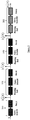
Claims (15)

  1. A method comprising:
    - obtaining transition parameters of at least one transform of a plurality of successive transforms, the output of a transform being used as the input of the following transform, at least one of said transition parameters encoding style characteristics of at least a part of a first visual object of a plurality of style visual objects;
    - modifying said successive transforms by taking account of at least one other parameter derived from a cost function representative of an image intrinsic property;
    - obtaining an output image from a part of an input visual object by applying successively said modified transforms, said part of said input visual object being used as the input of the first of said transforms.
  2. An electronic device comprising at least one memory and one or several processors configured for collectively:
    - obtaining transition parameters of at least one transform of a plurality of successive transforms, the output of a transform being used as the input of the following transform, at least one of said transition parameters encoding style characteristics of at least a part of a first visual object of a plurality of style visual objects;
    - modifying said successive transforms by taking account of at least one other parameter derived from a cost function representative of an image intrinsic property;
    - obtaining an output image from a part of an input visual object by applying successively said modified transforms, said part of said input visual object being used as the input of the first of said transforms.
  3. The method of claim 1 or the electronic device of claim 2 wherein each of successive transform is a sub-network of a deep neural network.
  4. The method of claim 1 or 3, or the electronic device of claim 2 or 3 wherein obtaining transition parameters comprises learning said transition parameters by minimizing a training loss function from feature maps of at least one training pair of images, each training pair comprising a training input visual object and one of said style visual objects.
  5. The method of claim 3 or 4, or the electronic device of claims 3 or 4, wherein said feature maps are computed by using a pre-trained deep neural network.
  6. The method of claim 1 or of any of claims 3 to 5, or the electronic device of any of claims 2 to 5, wherein said modifying is performed at run time.
  7. The method of claim 1 or of any of claims 3 to 6, or the electronic device of any of claims 2 to 6, wherein said modifying is performed in response to a first user request.
  8. The method of claim 7, or the electronic device of claim 7, wherein said at least one other parameter is weighted according to said first user request.
  9. The method of claim 1 or of any of claims 3 to 8, or the electronic device of any of claims 2 to 8, wherein said intrinsic property is a dynamic of a reference visual object.
  10. The method of claim 1 or of any of claims 3 to 9, or the electronic device of any of claims 2 to 9, wherein said intrinsic property relates to at least one of:
    - a photorealistic rendering;
    - a painting rendering;
    - a rendering by a limited set of colors; and/or
    - a preserving of local contrasts inside at least a part of said input visual object.
  11. The method of claim 1 or of any of claims 3 to 10, or the device of any of claims 2 to 10, comprising weighting parameters of at least one of said transforms.
  12. The method of claim 1 or of any of claims 3 to 11, or the device of any of claims 2 to 11, wherein said weighting is performed at run time.
  13. The method of claim 1 or of any of claims 3 to 12, or the device of any of claims 2 to 12, wherein said weighting is performed in response to a second user request.
  14. A non-transitory computer readable program product, comprising program code instructions for performing, when said non-transitory software program is executed by a computer, a method comprising:
    - obtaining transition parameters of at least one transform of a plurality of successive transforms, the output of a transform being used as the input of the following transform, at least one of said transition parameters encoding style characteristics of at least a part of a first visual object of a plurality of style visual objects;
    - modifying said successive transforms by taking account of at least one other parameter derived from a cost function representative of an image intrinsic property;
    - obtaining an output image from a part of an input visual object by applying successively said modified transforms, said part of said input visual object being used as the input of the first of said transforms.
  15. Computer readable storage medium carrying a software program characterized in that it comprises program code instructions for performing, when said non-transitory software program is executed by a computer, a method comprising:
    - obtaining transition parameters of at least one transform of a plurality of successive transforms, the output of a transform being used as the input of the following transform, at least one of said transition parameters encoding style characteristics of at least a part of a first visual object of a plurality of style visual objects;
    - modifying said successive transforms by taking account of at least one other parameter derived from a cost function representative of an image intrinsic property;
    - obtaining an output image from a part of an input visual object by applying successively said modified transforms, said part of said input visual object being used as the input of the first of said transforms.
EP18305264.6A 2018-03-13 2018-03-13 Method for transfer of a style of a reference visual object to another visual object, and corresponding electronic device, computer readable program products and computer readable storage medium Withdrawn EP3540695A1 (en)

Priority Applications (1)

Application Number Priority Date Filing Date Title
EP18305264.6A EP3540695A1 (en) 2018-03-13 2018-03-13 Method for transfer of a style of a reference visual object to another visual object, and corresponding electronic device, computer readable program products and computer readable storage medium

Applications Claiming Priority (1)

Application Number Priority Date Filing Date Title
EP18305264.6A EP3540695A1 (en) 2018-03-13 2018-03-13 Method for transfer of a style of a reference visual object to another visual object, and corresponding electronic device, computer readable program products and computer readable storage medium

Publications (1)

Publication Number Publication Date
EP3540695A1 true EP3540695A1 (en) 2019-09-18

Family

ID=61800437

Family Applications (1)

Application Number Title Priority Date Filing Date
EP18305264.6A Withdrawn EP3540695A1 (en) 2018-03-13 2018-03-13 Method for transfer of a style of a reference visual object to another visual object, and corresponding electronic device, computer readable program products and computer readable storage medium

Country Status (1)

Country Link
EP (1) EP3540695A1 (en)

Cited By (2)

* Cited by examiner, † Cited by third party
Publication number Priority date Publication date Assignee Title
CN110909790A (en) * 2019-11-20 2020-03-24 Oppo广东移动通信有限公司 Image style transfer method, device, terminal and storage medium
CN120807333A (en) * 2025-09-15 2025-10-17 杭州定川信息技术有限公司 Gradient descent scene consistency adjusting method for fixed scene

Citations (1)

* Cited by examiner, † Cited by third party
Publication number Priority date Publication date Assignee Title
US20180068463A1 (en) * 2016-09-02 2018-03-08 Artomatix Ltd. Systems and Methods for Providing Convolutional Neural Network Based Image Synthesis Using Stable and Controllable Parametric Models, a Multiscale Synthesis Framework and Novel Network Architectures

Patent Citations (1)

* Cited by examiner, † Cited by third party
Publication number Priority date Publication date Assignee Title
US20180068463A1 (en) * 2016-09-02 2018-03-08 Artomatix Ltd. Systems and Methods for Providing Convolutional Neural Network Based Image Synthesis Using Stable and Controllable Parametric Models, a Multiscale Synthesis Framework and Novel Network Architectures

Non-Patent Citations (6)

* Cited by examiner, † Cited by third party
Title
DONGDONG CHEN ET AL: "StyleBank: An Explicit Representation for Neural Image Style Transfer", ARXIV.ORG, CORNELL UNIVERSITY LIBRARY, 201 OLIN LIBRARY CORNELL UNIVERSITY ITHACA, NY 14853, 27 March 2017 (2017-03-27), XP080755790, DOI: 10.1109/CVPR.2017.296 *
GATYS L.; ECKER A.; BETHGE M.: "Image style transfer using convolutional neural networks", CVPR, 2016
GILLES PUY ET AL: "A Flexible Convolutional Solver with Application to Photorealistic Style Transfer", ARXIV.ORG, CORNELL UNIVERSITY LIBRARY, 201 OLIN LIBRARY CORNELL UNIVERSITY ITHACA, NY 14853, 14 June 2018 (2018-06-14), XP080890489 *
LEON A GATYS ET AL: "Image Style Transfer Using Convolutional Neural Networks", June 2016 (2016-06-01), pages 1 - 10, XP055298103, Retrieved from the Internet <URL:http://www.cv-foundation.org/openaccess/content_cvpr_2016/papers/Gatys_Image_Style_Transfer_CVPR_2016_paper.pdf> [retrieved on 20160829], DOI: 10.1109/CVPR.2016.265 *
LEVIN, LISCHINSKI; WEISS: "A Closed-Form Solution to Natural Image Matting", IEEE PAMI, vol. 30, no. 2, 2008, pages 228 - 242, XP011195582, DOI: doi:10.1109/TPAMI.2007.1177
YIJUN LI ET AL: "A Closed-form Solution to Photorealistic Image Stylization", ARXIV:1802.06474V3, 22 February 2018 (2018-02-22), arXiv, pages 1 - 12, XP055506685, Retrieved from the Internet <URL:https://arxiv.org/pdf/1802.06474v3.pdf> [retrieved on 20180912] *

Cited By (2)

* Cited by examiner, † Cited by third party
Publication number Priority date Publication date Assignee Title
CN110909790A (en) * 2019-11-20 2020-03-24 Oppo广东移动通信有限公司 Image style transfer method, device, terminal and storage medium
CN120807333A (en) * 2025-09-15 2025-10-17 杭州定川信息技术有限公司 Gradient descent scene consistency adjusting method for fixed scene

Similar Documents

Publication Publication Date Title
Su et al. Pixel-adaptive convolutional neural networks
CN113674146B (en) Super resolution of image
Eboli et al. End-to-end interpretable learning of non-blind image deblurring
KR101871098B1 (en) Apparatus and method for image processing
CN112602088B (en) Methods, systems and computer-readable media for improving the quality of low-light images
CN112446834A (en) Image enhancement method and device
KR100924689B1 (en) Image converting device and method for mobile devices
US20230082050A1 (en) Universal style transfer using multi-scale feature transform and user controls
Nguyen et al. Raw image reconstruction using a self-contained srgb–jpeg image with small memory overhead
CN118762286B (en) YOLOv 8-improved algorithm-based weed classification detection method and system
CN118608389A (en) Real-time dynamic super-resolution image reconstruction method and reconstruction system
CN114742733A (en) Cloud removal method, apparatus, computer equipment and storage medium
CN115496654A (en) Image super-resolution reconstruction method, equipment and medium based on self-attention mechanism
US20240119721A1 (en) Processing data using convolution as a transformer operation
WO2024210992A2 (en) Generating semantically-labelled three-dimensional models
CN110874575A (en) A face image processing method and related equipment
US20130114892A1 (en) Method and device for generating a super-resolution image portion
CN114022402B (en) Image processing method and device
CN117974441A (en) Method, apparatus and computer program product for image processing
Zhou et al. Dark light enhancement for dark scene urban object recognition
KR101795952B1 (en) Method and device for generating depth image of 2d image
CN119540511A (en) Image enhancement method and system
Parvaz Point spread function estimation for blind image deblurring problems based on framelet transform
US12079957B2 (en) Modeling continuous kernels to generate an enhanced digital image from a burst of digital images
Malekijoo et al. Convolution-deconvolution architecture with the pyramid pooling module for semantic segmentation

Legal Events

Date Code Title Description
PUAI Public reference made under article 153(3) epc to a published international application that has entered the european phase

Free format text: ORIGINAL CODE: 0009012

AK Designated contracting states

Kind code of ref document: A1

Designated state(s): AL AT BE BG CH CY CZ DE DK EE ES FI FR GB GR HR HU IE IS IT LI LT LU LV MC MK MT NL NO PL PT RO RS SE SI SK SM TR

AX Request for extension of the european patent

Extension state: BA ME

STAA Information on the status of an ep patent application or granted ep patent

Free format text: STATUS: THE APPLICATION IS DEEMED TO BE WITHDRAWN

18D Application deemed to be withdrawn

Effective date: 20200603