EP3540678A1 - Machine tool management system - Google Patents
Machine tool management system Download PDFInfo
- Publication number
- EP3540678A1 EP3540678A1 EP17871643.7A EP17871643A EP3540678A1 EP 3540678 A1 EP3540678 A1 EP 3540678A1 EP 17871643 A EP17871643 A EP 17871643A EP 3540678 A1 EP3540678 A1 EP 3540678A1
- Authority
- EP
- European Patent Office
- Prior art keywords
- machine tool
- information
- user
- monitoring device
- usage
- Prior art date
- Legal status (The legal status is an assumption and is not a legal conclusion. Google has not performed a legal analysis and makes no representation as to the accuracy of the status listed.)
- Granted
Links
Images



Classifications
-
- G—PHYSICS
- G06—COMPUTING OR CALCULATING; COUNTING
- G06Q—INFORMATION AND COMMUNICATION TECHNOLOGY [ICT] SPECIALLY ADAPTED FOR ADMINISTRATIVE, COMMERCIAL, FINANCIAL, MANAGERIAL OR SUPERVISORY PURPOSES; SYSTEMS OR METHODS SPECIALLY ADAPTED FOR ADMINISTRATIVE, COMMERCIAL, FINANCIAL, MANAGERIAL OR SUPERVISORY PURPOSES, NOT OTHERWISE PROVIDED FOR
- G06Q20/00—Payment architectures, schemes or protocols
- G06Q20/08—Payment architectures
- G06Q20/14—Payment architectures specially adapted for billing systems
- G06Q20/145—Payments according to the detected use or quantity
-
- G—PHYSICS
- G06—COMPUTING OR CALCULATING; COUNTING
- G06Q—INFORMATION AND COMMUNICATION TECHNOLOGY [ICT] SPECIALLY ADAPTED FOR ADMINISTRATIVE, COMMERCIAL, FINANCIAL, MANAGERIAL OR SUPERVISORY PURPOSES; SYSTEMS OR METHODS SPECIALLY ADAPTED FOR ADMINISTRATIVE, COMMERCIAL, FINANCIAL, MANAGERIAL OR SUPERVISORY PURPOSES, NOT OTHERWISE PROVIDED FOR
- G06Q30/00—Commerce
- G06Q30/02—Marketing; Price estimation or determination; Fundraising
- G06Q30/0283—Price estimation or determination
-
- G—PHYSICS
- G05—CONTROLLING; REGULATING
- G05B—CONTROL OR REGULATING SYSTEMS IN GENERAL; FUNCTIONAL ELEMENTS OF SUCH SYSTEMS; MONITORING OR TESTING ARRANGEMENTS FOR SUCH SYSTEMS OR ELEMENTS
- G05B19/00—Program-control systems
- G05B19/02—Program-control systems electric
- G05B19/18—Numerical control [NC], i.e. automatically operating machines, in particular machine tools, e.g. in a manufacturing environment, so as to execute positioning, movement or co-ordinated operations by means of program data in numerical form
- G05B19/406—Numerical control [NC], i.e. automatically operating machines, in particular machine tools, e.g. in a manufacturing environment, so as to execute positioning, movement or co-ordinated operations by means of program data in numerical form characterised by monitoring or safety
- G05B19/4063—Monitoring general control system
-
- G—PHYSICS
- G05—CONTROLLING; REGULATING
- G05B—CONTROL OR REGULATING SYSTEMS IN GENERAL; FUNCTIONAL ELEMENTS OF SUCH SYSTEMS; MONITORING OR TESTING ARRANGEMENTS FOR SUCH SYSTEMS OR ELEMENTS
- G05B19/00—Program-control systems
- G05B19/02—Program-control systems electric
- G05B19/418—Total factory control, i.e. centrally controlling a plurality of machines, e.g. direct or distributed numerical control [DNC], flexible manufacturing systems [FMS], integrated manufacturing systems [IMS] or computer integrated manufacturing [CIM]
-
- G—PHYSICS
- G06—COMPUTING OR CALCULATING; COUNTING
- G06Q—INFORMATION AND COMMUNICATION TECHNOLOGY [ICT] SPECIALLY ADAPTED FOR ADMINISTRATIVE, COMMERCIAL, FINANCIAL, MANAGERIAL OR SUPERVISORY PURPOSES; SYSTEMS OR METHODS SPECIALLY ADAPTED FOR ADMINISTRATIVE, COMMERCIAL, FINANCIAL, MANAGERIAL OR SUPERVISORY PURPOSES, NOT OTHERWISE PROVIDED FOR
- G06Q10/00—Administration; Management
-
- G—PHYSICS
- G06—COMPUTING OR CALCULATING; COUNTING
- G06Q—INFORMATION AND COMMUNICATION TECHNOLOGY [ICT] SPECIALLY ADAPTED FOR ADMINISTRATIVE, COMMERCIAL, FINANCIAL, MANAGERIAL OR SUPERVISORY PURPOSES; SYSTEMS OR METHODS SPECIALLY ADAPTED FOR ADMINISTRATIVE, COMMERCIAL, FINANCIAL, MANAGERIAL OR SUPERVISORY PURPOSES, NOT OTHERWISE PROVIDED FOR
- G06Q30/00—Commerce
- G06Q30/06—Buying, selling or leasing transactions
-
- G—PHYSICS
- G06—COMPUTING OR CALCULATING; COUNTING
- G06Q—INFORMATION AND COMMUNICATION TECHNOLOGY [ICT] SPECIALLY ADAPTED FOR ADMINISTRATIVE, COMMERCIAL, FINANCIAL, MANAGERIAL OR SUPERVISORY PURPOSES; SYSTEMS OR METHODS SPECIALLY ADAPTED FOR ADMINISTRATIVE, COMMERCIAL, FINANCIAL, MANAGERIAL OR SUPERVISORY PURPOSES, NOT OTHERWISE PROVIDED FOR
- G06Q30/00—Commerce
- G06Q30/06—Buying, selling or leasing transactions
- G06Q30/0645—Rental transactions; Leasing transactions
-
- G—PHYSICS
- G06—COMPUTING OR CALCULATING; COUNTING
- G06Q—INFORMATION AND COMMUNICATION TECHNOLOGY [ICT] SPECIALLY ADAPTED FOR ADMINISTRATIVE, COMMERCIAL, FINANCIAL, MANAGERIAL OR SUPERVISORY PURPOSES; SYSTEMS OR METHODS SPECIALLY ADAPTED FOR ADMINISTRATIVE, COMMERCIAL, FINANCIAL, MANAGERIAL OR SUPERVISORY PURPOSES, NOT OTHERWISE PROVIDED FOR
- G06Q50/00—Information and communication technology [ICT] specially adapted for implementation of business processes of specific business sectors, e.g. utilities or tourism
- G06Q50/04—Manufacturing
-
- G—PHYSICS
- G07—CHECKING-DEVICES
- G07F—COIN-FREED OR LIKE APPARATUS
- G07F17/00—Coin-freed apparatus for hiring articles; Coin-freed facilities or services
- G07F17/0042—Coin-freed apparatus for hiring articles; Coin-freed facilities or services for hiring of objects
-
- G—PHYSICS
- G05—CONTROLLING; REGULATING
- G05B—CONTROL OR REGULATING SYSTEMS IN GENERAL; FUNCTIONAL ELEMENTS OF SUCH SYSTEMS; MONITORING OR TESTING ARRANGEMENTS FOR SUCH SYSTEMS OR ELEMENTS
- G05B2219/00—Program-control systems
- G05B2219/30—Nc systems
- G05B2219/31—From computer integrated manufacturing till monitoring
- G05B2219/31408—Cost calculation of use of certain machine types
-
- Y—GENERAL TAGGING OF NEW TECHNOLOGICAL DEVELOPMENTS; GENERAL TAGGING OF CROSS-SECTIONAL TECHNOLOGIES SPANNING OVER SEVERAL SECTIONS OF THE IPC; TECHNICAL SUBJECTS COVERED BY FORMER USPC CROSS-REFERENCE ART COLLECTIONS [XRACs] AND DIGESTS
- Y02—TECHNOLOGIES OR APPLICATIONS FOR MITIGATION OR ADAPTATION AGAINST CLIMATE CHANGE
- Y02P—CLIMATE CHANGE MITIGATION TECHNOLOGIES IN THE PRODUCTION OR PROCESSING OF GOODS
- Y02P90/00—Enabling technologies with a potential contribution to greenhouse gas [GHG] emissions mitigation
- Y02P90/02—Total factory control, e.g. smart factories, flexible manufacturing systems [FMS] or integrated manufacturing systems [IMS]
-
- Y—GENERAL TAGGING OF NEW TECHNOLOGICAL DEVELOPMENTS; GENERAL TAGGING OF CROSS-SECTIONAL TECHNOLOGIES SPANNING OVER SEVERAL SECTIONS OF THE IPC; TECHNICAL SUBJECTS COVERED BY FORMER USPC CROSS-REFERENCE ART COLLECTIONS [XRACs] AND DIGESTS
- Y02—TECHNOLOGIES OR APPLICATIONS FOR MITIGATION OR ADAPTATION AGAINST CLIMATE CHANGE
- Y02P—CLIMATE CHANGE MITIGATION TECHNOLOGIES IN THE PRODUCTION OR PROCESSING OF GOODS
- Y02P90/00—Enabling technologies with a potential contribution to greenhouse gas [GHG] emissions mitigation
- Y02P90/30—Computing systems specially adapted for manufacturing
Definitions
- the present invention relates to a machine tool management system which manages, through the Internet, at least one machine tool disposed at a location available to a specified or unspecified user.
- the user's management device is connected to a numerical control part (controller) of at least one machine tool, the machine tool including a drive mechanism unit and the numerical control part that controls operation of the drive mechanism unit.
- the user's management device includes user-side operational data storing means and data transmitting means, the use-side operational data storing means storing data on an operational status of the drive mechanism unit of the machine tool, the data transmitting means collecting data on the operational status of the drive mechanism unit from the numerical control part, accumulating the data in the user-side operational data storing means, checking whether predetermined transmission conditions are satisfied, and, only when the transmission conditions are satisfied, transmitting the operational status data of the drive mechanism unit accumulated in the use-side operational data storing means to the manufacturer's management device in an email form.
- the manufacturer's management device includes a manufacturer-side operational data storing means, data receiving means, consumption degree data storing means, consumption degree evaluating means, and alarm outputting means, the manufacturer-side operational data storing means storing the operational status data of the drive mechanism unit received from the user's management device, the data receiving means receiving the operational status data of the drive mechanism unit transmitted from the user's management device and updating the operational status data stored in the manufacturer-side operational data storing means with the received operational status data, the consumption degree data storing means storing data on a degree of consumption of the drive mechanism unit, the consumption degree evaluating means occasionally evaluating the degree of consumption of the drive mechanism unit based on the operational status data of the drive mechanism unit stored in the manufacturer-side operational data storing means and updating the consumption degree data stored in the consumption degree data storing means with the evaluated consumption degree data, and the alarm outputting means occasionally monitoring whether the consumption degree data stored in the consumption degree data storing means exceeds a predetermined reference value, and when the data exceeds the reference value, outputting an alarm providing
- the data transmitting means of the user's management device collects data on an operational status (operational status data) of the drive mechanism unit from the numerical control part of the machine tool, and the collected data is accumulated in the user-side operational data storing means. It is occasionally checked whether predetermined transmission conditions are satisfied, and only when the transmission conditions are satisfied, the operational status data of the drive mechanism unit accumulated in the user-side operational data storing means is transmitted to the manufacturer's management device in an email form.
- the transmitted operational status data is received by the data receiving means, and the operational status data of the drive mechanism unit stored in the manufacturer-side operational data storing means is updated with the received operational status data.
- the consumption degree evaluating means occasionally evaluates the degree of consumption of the drive mechanism unit based on the operational status data of the drive mechanism unit stored in the manufacturer-side operational data storing means, and updates the consumption degree data stored in the consumption degree data storing means with the evaluated consumption degree data.
- the alarm outputting means occasionally monitors whether the consumption degree data stored in the consumption degree data storing means exceeds a predetermined reference value, and, upon confirming that the data exceeds the reference value, outputs an alarm providing a notice of the exceeding.
- this maintenance management system is configured such that the degree of consumption of the drive mechanism unit of the machine tool is occasionally evaluated and monitored, and when the degree of consumption exceeds a predetermined reference value, that is, when a consumable part of the drive mechanism unit approaches the end of its life, an alarm is output. Therefore, the manufacturer can easily recognize a consumable part approaching the end of its life based on the output alarm, which enables the manufacturer to predict when, how many, and which consumable part is needed. Consequently, the manufacturer does not have to excessively keep socks of consumable parts and therefore can greatly reduce the stocks of the consumable parts.
- Patent Literature 1 Japanese Unexamined Patent Application Publication No. 2004-295348
- machining lathe which has lathe elements as a basic structure but is adapted to be capable of milling, and highly functional machine tools, such as a machining center capable of 5-axis machining, which are able to perform advanced and complicated machining
- machine tools including an automatic tool changer (ATC), an automatic pallet changer (APC), a tool measurement system, or a workpiece measuring system; that is to say, a wide variety of machine tools have been provided.
- peripheral devices for the purpose of automation such as a robot and a loader for loading and attachment/removal of a workpiece, also have been provided.
- Such a system needs to satisfy the condition that the machine tool can be installed in any region, and needs to execute its processings efficiently, it is preferable that such a system is a system using the Internet.
- the present invention has been achieved in view of the above-described circumstances, and an object thereof is to provide a machine tool management system which allows a machine tool to be installed in any region and can charge a user a use fee corresponding to usage of the machine tool efficiently.
- the present invention for solving the above-described problems, relates to a machine tool management system including:
- the at least one machine tool is disposed at a location available to a specified or unspecified user.
- the machine tool In the case of a machine tool being used by a specified user, for example, the machine tool is disposed in a plant owned by the user. In contrast, in the case of a machine tool being used by an unspecified user, for example, the machine tool is disposed in a building arranged by the machine tool manufacturer.
- the machine tool has a use monitoring device attached thereto, the use monitoring device being connected to the Internet and being able to communicate with the management device that is also connected to the Internet.
- the management device is under management by the machine tool manufacturer; however, the management device can be installed at any location.
- the use monitoring device attached to the machine tool transmits information on usage of the machine tool to the management device.
- the information on the usage of the machine tool forms the basis of calculation for charging the user a commensurate cost for the use of the machine tool.
- the information includes an operating time of the machine tool.
- the management device calculates, as a use fee, a cost corresponding to the usage of the machine tool received from the use monitoring device and executes a processing of charging the calculated use fee to the user.
- the user does not have to purchase the machine tool and can perform necessary machining only by paying a use fee corresponding to usage of the machine tool. Therefore, even in the case where the amount of work the user has is not so large as to cause the machine tool to run at full capacity, the user can perform machining corresponding to the amount of work without installing a new machine tool; therefore, the user can accommodate demand. Further, paying a use fee corresponding to usage of the machine tool as described above allows the user to replace the existing machine tool with a state-of-the-art machine tool without making capital expenditure. Therefore, replacement of equipment is promoted even in the case where the user does not have stable demand or even in the case where there is a risk such as sudden fluctuation in demand.
- the machine tool manufacturer can realize a stable planned production that facilitates obtaining profits. Further, since the management system is a system using the Internet, the machine tool can be installed in any region. For example, the machine tool can be installed abroad, and, even in such a case where the machine tool is installed abroad, the charging processing can be executed efficiently.
- the management device is configured to make settlement of the use fee charged to the user, by executing a processing in cooperation with the use monitoring device.
- Such cooperative settlement means electronic settlement through the Internet, where the user uses the use monitoring device to make settlement of the cost charged to the user by the management device.
- Examples of the cooperative settlement include settlement by a credit card and settlement by automatic withdrawal from the user's bank account.
- the machine tool may have provided therein associated facility and function to be used in machining performed with the machine tool, and the use monitoring device may be configured to transmit the information on the usage of the machine tool inclusive of information on usage of the associated facility and function to the management device.
- the associated facility and function include, for example, an automatic programming apparatus, an interactive programming apparatus, a special cycle function, a tool measurement system, and a workpiece measurement system.
- the user wants to use such an associated facility or such an associated function.
- the user can use the associated facility and function as necessary, and the machine tool manufacturer can charge the user a cost corresponding to usage of the associated facility and function.
- the machine tool may include a turning mechanism as a basic mechanism and include, as an additional mechanism, one or more mechanisms selected from among a tailstock mechanism, a steady rest mechanism, a milling mechanism, second and subsequent tool rests, second and subsequent spindle mechanisms, and a coolant mechanism; and the use monitoring device may be configured to transmit the information on the usage of the machine tool inclusive of information on usage of the additional mechanism to the management device.
- the user wants to use the additional mechanism in addition to the turning mechanism that is the basic mechanism.
- the user can use the additional mechanism as necessary, and the machine tool manufacturer can charge the user a cost corresponding to usage of the additional mechanism.
- the machine tool may include a milling mechanism as a basic mechanism and include, as an additional mechanism, one or more mechanisms selected from among a rotating shaft other than a tool spindle, a mechanism associated with a U-shaft of the tool spindle, a workpiece clamping mechanism, and a coolant mechanism; and the use monitoring device may be configured to transmit the information on the usage of the machine tool inclusive of information on usage of the additional mechanism to the management device.
- the user wants to use the additional mechanism in addition to the milling mechanism that is the basic mechanism.
- the user can use the additional mechanism as necessary, and the machine tool manufacturer can charge the user a cost corresponding to usage of the additional mechanism.
- the machine tool may include a main mechanism performing machining, and a peripheral mechanism provided around the main mechanism; and the use monitoring device may be configured to transmit the information on the usage of the machine tool inclusive of information on usage of the peripheral mechanism to the management device.
- the peripheral mechanism includes, for example, a robot and a workpiece loading/unloading apparatus.
- the user wants to use the peripheral mechanism in addition to the main mechanism.
- the user can use the peripheral mechanism as necessary, and the machine tool manufacturer can charge the user a cost corresponding to usage of the peripheral mechanism.
- the main mechanism as used herein, has a concept including the basic mechanism and the additional mechanism.
- an accessory instrument to be used in machining performed with the machine tool may be provided around the machine tool; and the use monitoring device may be configured to transmit the information on the usage of the machine tool inclusive of information on usage of the accessory instrument to the management device.
- the accessory instrument includes, for example, a chuck, a soft jaw, a tool (including a tool holder), a throw-away tip, and a detachable measurement instrument.
- the user wants to use the accessory instrument that can be used in the machine tool, in addition to the machine tool. With this configuration, the user can use the accessory instrument as necessary, and the machine tool manufacturer can charge the user a cost corresponding to usage of the accessory instrument.
- the machine tool may have provided therein various sensors each detecting a status of the machine tool; and the use monitoring device may be configured to transmit information obtained from the various sensors, as the information on the usage of the machine tool, to the management device.
- the sensors include, for example, an electric power meter, a motor load ammeter, an accelerometer, and a thermometer
- the information obtained from the sensors includes, for example, electric energy data, spindle motor load data, feed motor load data, vibration data of each machine tool part, and temperature data of each machine tool part. Collecting such information enables obtaining of data on a load status of the machine tool and data on performance of the machine tool against load; the data obtained can be utilized in development and improvement of a machine tool of the next version.
- the management device may be configured to analyze the information obtained from the various sensors received from the use monitoring device, determine whether the machine tool has an abnormality or whether the machine tool is predicted to fall into a state of having an abnormality, and, when it is confirmed that the machine tool has an abnormality or when the machine tool is predicted to fall into the state of having an abnormality, transmit a signal relating to the abnormality to the use monitoring device.
- the user can use the machine tool with a sense of security.
- the expression "the machine tool is predicted to fall into a state of having an abnormality” means that the machine tool will fall into a state of having an abnormality in the near future, the near feature meaning, for example, a future determined by the number of days which allows the machine tool manufacturer to resolve the abnormality before the machine tool falls into the state of having the abnormality.
- the use monitoring device may be configured to transmit data on an operational status obtained from the machine tool to the management device; and the management device may be configured to accumulate the received data on the operational status, and analyze the accumulated data to store the data at least as production technology information.
- the data on the operational status includes, for example, cutting conditions (including a cutting speed, a feed speed, a workpiece material, and a tool material), tool life data, and data on spindle rotation speed, etc. Transmitting such operational information to the management device enables accumulation of a wide variety of production technology information in the management device, and analyzing, editing, and systematizing the accumulated production technology information as appropriate makes the production technology information versatile and highly reliable.
- the use monitoring device may be configured to execute a processing of requesting permission from the management device to use the production technology information stored in the management device; and the management device may be configured to calculate the use fee for the machine tool according to use/non-use of the production technology information.
- the production technology information is collected in the management device; therefore, versatile and highly reliable production technology information is accumulated in the management device. Therefore, the user can utilize the production technology information to more properly perform machining. On the other hand, the machine tool manufacturer can obtain commensurate profits by providing the accumulated production technology information to the user and charging the user the use fee according to use of the production technology information.
- the machine tool may be disposed at a location available to an unspecified user;
- the use monitoring device may be configured to execute a processing of requesting permission from the management device to use the machine tool, and when obtaining the permission from the management device, execute a processing of making the machine tool operational;
- the management device may be configured to, when receiving a signal requesting permission to use the machine tool from the use monitoring device, execute a processing of recognizing the user and execute a processing of judging permissibility and sending a reply to the use monitoring device.
- the machine tool is disposed at a location available to an unspecified user. Further, the use monitoring device executes a processing of requesting permission from the management device to use the machine tool, and when obtaining the permission from the management device, executes a processing of making the machine tool operational.
- the management device executes a processing of recognizing the user and executes a processing of judging permissibility and sending a reply to the use monitoring device.
- the user can use the machine tool only when the user is recognized by the management device and permitted to use the machine tool. Therefore, it is possible to eliminate use by a user who has used the machine tool in an improper manner and use by a user who has not made proper settlement, which enables proper operation of the system and increased safety.
- the user does not have to purchase the machine tool and can perform necessary machining only by paying a use fee corresponding to usage of the machine tool. Therefore, even in the case where the amount of work the user has is not so large as to cause the machine tool to run at full capacity, the user can perform machining corresponding to the amount of work without installing a new machine tool; therefore, the user can accommodate demand. Further, paying a use fee corresponding to usage of the machine tool as described above allows the user to replace the existing machine tool with a state-of-the-art machine tool without making capital expenditure. Therefore, replacement of equipment is promoted even in the case where the user does not have stable demand or even in the case where there is a risk such as sudden fluctuation in demand.
- the machine tool manufacturer can achieve a stable planned production that facilitates obtaining profits. Further, since the management system is a system using the Internet, the machine tool can be installed in any region. For example, the machine tool can be installed abroad, and, even in such a case where the machine tool is installed abroad, the charging processing can be executed efficiently.
- FIG. 1 is a block diagram showing a schematic configuration of a machine tool management system (hereinafter, simply referred to as "management system”) according to the embodiment.
- the management system 1 is composed of a management device 10 connected to Internet 2 and a plurality of machine tools 101 each having a use monitoring device 110 attached thereto, the use monitoring device 110 being connected to the Internet 2.
- Each machine tool 101 is disposed at a location available to a specified user, e.g., in a machining plant owned by a specified user, or a location available to an unspecified user, e.g., in a building arranged by the machine tool manufacturer.
- the building arranged by the machine tool manufacturer is available to a number of unspecified users, and has a concept like "machine center”.
- the management device 10 is under management by the machine tool manufacturer; however, the management device 10 can be installed at any location.
- each component is described in detail.
- each machine tool 101 includes a basic mechanism 102 and an additional mechanism 103.
- the machine tool 101 has provided therein associated facility and function (hereinafter referred to as "associated facility") 104, a peripheral mechanism 105, and various sensors 107, and has provided therearound an accessory instrument 106.
- associated facility associated facility and function
- the basic mechanism 102 and the additional mechanism 103 perform machining, and they are regarded as constituting a main mechanism.
- the machine tool 101 can be of any type, examples of which include an NC lathe and a machining center, which are most common.
- the basic mechanism 102 is a turning mechanism
- the additional mechanism 103 is, for example, one or more mechanisms selected from among a tailstock mechanism, a steady rest mechanism, a milling mechanism, second and subsequent tool rests, second and subsequent spindle mechanisms, and a coolant mechanism.
- the basic mechanism 102 is a milling mechanism
- the additional mechanism 103 is, for example, one or more mechanisms selected from among a rotating shaft other than a tool spindle, a mechanism associated with a U-shaft of the tool spindle, a workpiece clamping mechanism, and a coolant mechanism.
- the associated facility 104 is a facility or function incorporated in or attached to the machine tool 101, examples of which include an automatic programming apparatus, an interactive programming apparatus, a special cycle function, a tool measurement system, and a workpiece measurement system.
- the peripheral mechanism 105 is a mechanism provided around the basic mechanism 102 and additional mechanism 103 (main mechanism) performing machining, examples of which include a robot and a workpiece loading/unloading apparatus (including a loader and the like).
- the accessory instrument 106 is an instrument to be used in machining performed with the machine tool 101, which is disposed around the machine tool 101.
- the accessory instrument 106 includes, for example, a chuck, a soft jaw, a tool (including a tool holder), a throw-away tip, and a detachable measurement instrument.
- the machine tool 101 has attached thereto the sensors 107.
- the sensors 107 include, for example, an electric power meter, a motor load ammeter, an accelerometer, and a thermometer.
- the sensors 107 provide, for example, information such as electric energy data, spindle motor load data, feed motor load data, vibration data of each machine tool part, and temperature data of each machine tool part.
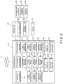
- each use monitoring device 110 consists of functional units: a use permission request part 111, a use permission processing part 112, a user registration application part 113, an identification information display part 114, a settlement processing part 115, a usage information obtaining part 116, a usage information storage 117, a usage information transmission part 118, a sensor information obtaining part 119, a sensor information storage 120, a sensor information transmission part 121, an operational information obtaining part 122, an operational information storage 123, an operational information transmission part 124, a production technology information request part 125, a production technology information display part 126, an abnormal signal receiving part 127, and an abnormality display part 128.
- the use monitoring device 110 is composed of a typical computer including a CPU, an ROM, and an RAM, as well as an input device, such as a keyboard or the like, and a display.
- the functions of the use permission request part 111, use permission processing part 112, user registration application part 113, identification information display part 114, settlement processing part 115, usage information obtaining part 116, usage information transmission part 118, sensor information obtaining part 119, sensor information transmission part 121, operational information obtaining part 122, operational information transmission part 124, production technology information request part 125, production technology information display part 126, abnormal signal receiving part 127, and abnormality display part 128 are each implemented by appropriate software.
- the usage information storage 117, the sensor information storage 120, and the operational information storage 123 are composed of an appropriate storage medium, such as an RAM or the like.
- the use permission request part 111 transmits information on the input identification information and usage particulars to the management device 10 and requests permission from the management device 10 to use the machine tool 101.
- the use permission processing part 112 Upon receiving a use permitting signal from the management device 10, the use permission processing part 112 transmits a use permission signal to a controller of the machine tool 101.
- the controller brings an operation panel in a non-operational state (locked state) into an operational state (unlocked state), thereby enabling operation of the machine tool 101.
- the use permission processing part 112 displays on the display the receiving of the not-permitting signal. In this case, the machine tool 101 is maintained at the non-operational state (locked state).
- the user registration application part 113 executes a processing. That is, once the user inputs information needed for registration, the user registration application part 113 transmits the input registration information to the management device 10.
- the transmitted registration information is registered by a user registration processing part 11, which is described in detail later, and identification information for the user is transmitted from the management device 10 to the use monitoring device 110.
- the received identification information is displayed on the display through a processing by the identification information display part 114.
- the registration information includes, for example, personal information, such as the user's address and name, and information needed for electronic settlement (e.g., credit card information, a bank account number available for withdrawal, or the like.).
- the user's identification information in association with information specific to the machine tool 101 or information specific to the user monitoring device 110 is transmitted to the management device 10 and registered by the user registration processing part 11.
- the usage information obtaining part 116 obtains usage information of the controller of the machine tool 101, associated facility 104, peripheral mechanism 105, and sensors 107 from them. Further, the usage information obtaining part 116 obtains information on the usage particulars, as usage information, from the use permission request part 111, obtains data on an operational status (operational information) of the controller of the machine tool 101, etc., as usage information, from them, and obtains, as usage information, the status of utilization of production technology information provided to the production technology information request part 125, which is described in detail later, by the management device 10.
- the usage information forms the basis of calculation for charging the user a commensurate cost for the use of the machine tool 101, the usage information including, for example, an operating time and a load status of the machine tool 101, use/non-use and operating times of the associated facility 104 and peripheral mechanism 105, use/non-use of the accessory instrument 106, and the status of utilization of the production technology information provided by the management device 10.
- the usage information obtaining part 116 obtains information on the use of the programming apparatus as usage information. Further, in a case where the controller of the machine tool 101 has equipped therewith special cycle functions, when the user selects any of the special cycle functions (e.g., when the user presses a button or icon for the special cycle function on a display of the controller), the usage information obtaining part 116 obtains information on the selection of the special cycle function as usage information. Furthermore, in a case where the machine tool 101 has equipped therewith a tool measurement system or a workpiece measurement system, when the user uses the measurement system, the usage information obtaining part 116 obtains information on the use of the measurement system as usage information.
- the usage information obtaining part 116 obtains information on the use of the measurement system as usage information.
- the usage information obtaining part 116 obtains use/non-use of the additional mechanism 103 as usage information based on NC codes of an NC program analyzed in the controller of the machine tool 101. Furthermore, in a case where a workpiece loading/unloading apparatus, such as a gantry loader, or a robot is provided as the peripheral mechanism 105, the usage information obtaining part 116 detects use/non-use of the peripheral mechanism 105 based on signals transmitted between the controller of the machine tool 101 and the peripheral mechanism 105 during operation, and obtains the detected use/non-use as usage information.
- a workpiece loading/unloading apparatus such as a gantry loader, or a robot
- the usage information obtaining part 116 detects an operational signal which is obtained from the dispenser when the user picks a necessary instrument from the dispenser, and obtains the detected operational signal as usage information.
- the usage information obtained from the sensors 107 includes, for example, electric energy data, spindle motor load data, and feed motor load data.
- the above-mentioned operational information includes information obtained through analysis of an NC program, e.g., rotational speed information (S codes) and feed information (F codes), as well as miscellaneous function information (M codes), such as on/off of hydraulic pressure for steady rest and the like.
- the usage information obtained by the usage information obtaining part 116 is stored into the usage information storage 117.
- the usage information stored in the usage information storage 117 is transmitted to the management device 10 by the usage information transmission part 118 at the point of time when the user ends the use of the machine tool 101.
- the sensor information obtaining part 119 obtains output data from the sensors 107 periodically or non-periodically and stores the obtained data into the sensor information storage 120.
- the data obtained from the sensors 107 includes, for example, electric energy data, spindle motor load data, feed motor load data, vibration data of each machine tool part and temperature data of each machine tool part.
- the data (sensor information) stored in the sensor information storage 120 is transmitted to the management device 10 by the sensor information transmission part 121 periodically or non-periodically until the user ends the use of the machine tool 101.
- the operational information obtaining part 122 obtains data on the operational status (operational information) of the controller of the machine tool 101, etc. from them, and stores the obtained data into the operational information storage 123.
- the operational information includes, for example, data on cutting conditions (including a cutting speed, a feed speed, a workpiece material, and a tool material) for a machining operation performed in the machine tool 101, tool life data, and data such as a spindle rotation speed.
- the operational information stored in the operational information storage 123 is transmitted to the management device 10 by the operational information transmission part 124 at the point of time when the user ends the use of the machine tool 101.
- the production technology information request part 125 requests the management device 10 to provide production technology information, to obtain necessary production technology information form the management device 10.
- the obtained production technology information is displayed on the display through the production technology information display part 126.
- the abnormal signal receiving part 127 receives an abnormal signal transmitted from the management device 10.
- the received abnormal signal is displayed on the display through the abnormality display part 128.
- the settlement processing part 115 makes an electronic settlement (e.g., a known credit card settlement) through the Internet 2 for a use fee charged by the management device 10, by executing a processing in cooperation with the management device 10.
- an electronic settlement e.g., a known credit card settlement
- the management device 10 consists of functional units: a user registration processing part 11, a user information storage 12, an identification information transmission part 13, an user information update part 114, a permissibility judgment part 15, a permissibility transmission part 16, a usage information receiving part 17, a use fee calculation part 18, a use fee unit price storage 19, a settlement processing part 20, a sensor information receiving part 21, a sensor information storage 22, an abnormality judgment part 23, an abnormal signal transmission part 24, an operational information receiving part 25, an information analysis part 26, a production technology information storage 27, a production technology request receiving part 28, and a production technology information transmission part 29.
- the management device 10 is also composed of a typical computer including a CPU, an ROM, and an RAM, as well as an input device, such as a keyboard or the like, and a display.
- the functions of the user registration processing part 11, identification information transmission part 13, user information update part 114, permissibility judgment part 15, permissibility transmission part 16, usage information receiving part 17, use fee calculation part 18, settlement processing part 20, sensor information receiving part 21, abnormality judgment part 23, abnormal signal transmission part 24, operational information receiving part 25, information analysis part 26, production technology request receiving part 28, and production technology information transmission part 29 are each implemented by appropriate software.
- the user information storage 12, the use fee unit price storage 19, the sensor information storage 22, and the production technology information storage 27 are composed of an appropriate storage medium, such as an RAM or the like.
- the user registration processing part 11 is a functional unit that accepts a registration application from the user registration application part 113 of each use monitoring device 110 and executes a registration processing for the user.
- the user registration processing part 11 accepts registration information transmitted from the user registration application part 113 and stores the accepted registration information into the user information storage 12. Further, the user registration processing part 11 generates identification information which is specific to the user, assigns the user the identification information, and stores the assigned identification information into the user information storage 12. Note that, as described above, in the case where the machine tool 101 is installed at a location used by a specified user, the user's identification information in association with the information specific to the machine tool 101 or the information specific to the use monitoring device 110 is stored into the user information storage 12.
- the assigned identification information is transmitted to the use monitoring device 110 by the identification information transmission part 13.
- the user information storage 12 is configured to store usage history and the status of settlement for each registered user. Based on information from the usage information receiving part 17 and from the settlement processing part 20, as well as information input externally in some cases, the information stored in the user information storage 12 is updated by the user information update part 14.
- the permissibility judgment part 15 receives a signal requesting use permission transmitted from the use permission processing part 111 of each use monitoring device 110, which is described in detail later, and judges whether the use permission requesting user can be permitted to use the machine tool 101. Specifically, the permissibility judgment part 15 checks the usage history and settlement status of the user by referring to the user information storage 12. When an improper usage is found in the usage history and/or it is confirmed that a settlement remains undone, the permissibility judgment part 15 makes a judgment that the user cannot be permitted to use the machine tool 101. Otherwise, the permissibility judgment part 15 makes a judgment that the user can be permitted to use the machine tool 101.
- the permissibility judgment part 15 may be configured such that, in the case where the machine tool 101 is installed at a location used by a specified user, the use permission requesting user is not permitted to use the machine tool 101 if the user is not the user corresponding to the machine tool 101. However, permitting the use permission requesting user to use the machine tool 101 even in such a case increases availability of the machine tool 101, which results in increase in the machine tool manufacturer's profits. Therefore, where there is no other problem, the permissibility judgment part 15 may be configured to permit many users to use the machine tool 101.
- the permissibility judgment part 15 makes a judgment about permissibility for the user in the above-described manner, the result of the judgment is transmitted to the use monitoring device 110 by the permissibility transmission part 16.
- the usage information receiving part 17 is a functional unit that receives the usage information transmitted from the usage information transmission part 18 of each use monitoring device 110, and forwards the received usage information to the use fee calculation part 18.
- the use fee calculation part 18 calculates a use fee for the user by referring to a use fee unit price for each item stored in the use fee unit price storage 19 based on the received usage information, and forwards the calculated use fee to the settlement processing part 20. For example, the use fee calculation part 18 calculates a basic use fee for use of the machine tool 101 by multiplying the operating of use by the unit price therefor, calculates an additional use fee based on the load status of the machine tool 101 and use/non-use of the associated facility 104, peripheral mechanism 105, accessory instrument 106, and production technology information, and then calculates a total use fee by adding up the basic use fee and the additional use fee.
- the unit prices may be varied according to the frequency of use of the associated facility or the like 104, peripheral mechanism 105, and accessory instrument 106. For example, a lower unit price is applied to a greater number of times of use, or a lower unit price is applied to a longer operating time. Further, points may be provided to the user according to use so that the user can use some functions or the like with no charge when a certain number of points is reached.
- the settlement processing part 20 transmits the use fee calculated by the use fee calculation part 18 to the use monitoring device 110, and makes electronic settlement of the use fee in cooperation with the settlement processing part 115 of the use monitoring device 110.
- the electronic settlement has been described above.
- the sensor information receiving part 21 is a functional unit that receives the sensor information transmitted from the sensor information transmission part 121 of each use monitoring device 110.
- the sensor information receiving part 21 stores the received sensor information into the sensor information storage 22 and forwards the received sensor information to the abnormality judgment part 23.
- the abnormality judgment part 23 analyzes the received sensor information and judges whether the machine tool 101 has any abnormality. When confirming that the machine tool 101 has an abnormality, the abnormality judgment part 23 transmits an abnormal signal relating to the abnormality to the use monitoring device 110 through the abnormal signal transmission part 24.
- the operational information receiving part 25 is a functional unit that receives the operational information transmitted from the operational information transmission part 124 of each use monitoring device 110, and forwards the received operational information to the information analysis part 26.
- the information analysis part 26 analyzes the received operational information to extract production technology information, edits and systematizes the extracted production technology information, and stores the edited and systematized production technology information into the production technology information storage 27.
- the production technology request receiving part 28 receives the request signal from the production technology information request part 125 of each use monitoring device 110 and forwards the received request signal to the production technology information transmission part 29.
- the production technology information transmission part 29 refers to the production technology information stored in the production technology information storage 27, reads out the production technology information corresponding to the received request signal, and transmits the read-out production technology information to the use monitoring device 110.
- step S1 the machine tool 101 and the corresponding use monitoring device 110 are actuated. Note that, at this moment, the user cannot operate the machine tool 101 yet.
- step S2 the user inputs, into the use monitoring device 110, his or her identification information as well as particulars (usage particulars) of the additional mechanism 103, associated facility 104, peripheral mechanism 105, and accessory instrument 106 to be used (step S2), information on the input identification information and use particulars together with a signal requesting use permission are transmitted from the use permission request part 111 to the management device 10 (step S3), and the transmitted information and signal are received by the permissibility judgment part 15.
- the permissibility judgment part 15 refers to the data stored in the user information storage 12 based on the received information on the identification information and usage particulars to check the usage history and settlement status of the user corresponding to the transmitted identification information (step S4). In the case where an improper use is found in the usage history and/or it is confirmed that a settlement remains undone, the permissibility judgment part 15 makes a judgment that the user cannot be permitted to use the machine tool 101. Otherwise, the permissibility judgment part 15 makes a judgment that the user can be permitted to use the machine tool 101. Thereafter, the permissibility judgment part 15 transmits the result of the judgment about permissibility of use of the machine tool 101 to the use monitoring device 110 through the permissibility transmission part 16 (step S5).
- the user registration application part 113 of the use monitoring device 110 and the user registration processing part 11 of the management device 10 execute the processing to assign the user identification information and register the user.
- the use permission processing part 112 of the use monitoring device 110 transmits a use permission signal to the controller of the machine tool 101 (step S6).
- the controller brings the operation panel in the non-operational state (locked state) into the operational state (unlocked state). Thereby, the machine tool 101 becomes ready for operation.
- the use permission processing part 112 displays on the display the receiving of the "impermissible” signal.
- step S7 the user uses the machine tool 101 to perform necessary machining.
- the user can utilize the production technology information accumulated in the production technology information storage 27 of the management device 10 through the production technology information request part 125 of the use monitoring device 110.
- the request is received by the production technology request receiving part 28 of the management device 10, which causes the production technology information transmission part 29 to search the production technology information accumulated in the production technology information storage 27 and transmit the requested production technology information to the use monitoring device 110 (step S9).
- the transmitted production technology information is displayed on the display through the production technology information display part 126 (step S10).
- the user can utilize the production technology information he or she requested.
- the usage information obtaining part 116 of the use monitoring device 110 obtains usage information of the controller of the machine tool 101, sensors 107, associated facility 104, and peripheral mechanism 105 from them, obtains the information on the usage particulars as usage information from the use permission processing part 111, and obtains, as usage information, the status of utilization of the production technology information obtained from the management device 10 through the production technology information request part 25, and the obtained usage information is stored into the usage information storage 117 (step S11).
- the sensor information obtaining part 119 of the use monitoring device 110 also stores data (sensor information) output from the sensors 107 into the sensor information storage 120 periodically or non-periodically, and the stored sensor information is transmitted to the management device 10 periodically or non-periodically by the sensor information transmission part 121 (step S12).
- the operational information obtaining part 122 also obtains data on the operational status (operational information) of the controller of the machine tool 101, etc. from them periodically or non-periodically, and stores the obtained data into the operational information storage 123, and the stored operational information is transmitted to the management device 10 periodically or non-periodically by the operational information transmission part 124 (step S15).
- the sensor information receiving part 21 receives the sensor information transmitted from the use monitoring device 110 and stores the received sensor information into the sensor information storage 22, and the abnormality judgment part 23 analyzes the received data and judges whether the machine tool 101 has any abnormality. In the case where it is confirmed that the machine tool 101 has an abnormality, an abnormal signal relating to the abnormality is transmitted to the use monitoring device 110 through the abnormal signal transmission part 24 (step S13). Once the abnormal signal is transmitted from the management device 10, the abnormal signal receiving part 127 of the use monitoring device 110 receives the abnormal signal and displays the received abnormal signal on the display through the abnormality display part 128 (step S14).
- the operational information receiving part 25 receives the operational information transmitted from the use monitoring device 110, and the information analysis part 26 analyzes the received operational information to extract production technology information, edits and systematizes the extracted production technology information, and then stores the edited and systematized production technology information into the production technology information storage 27 (step S16).
- step S17 When the user ends the machining operation (step S17), the usage information stored in the usage information storage 117 of the use monitoring device 110 is transmitted to the management device 10 by the usage information transmission part 118 (step S18).
- the use fee calculation part 18 calculates a use fee for the user by referring to the use fee unit price for each item stored in the use fee unit price storage 19 based on the received usage information, and forwards the calculated use fee to the settlement processing part 20 (step S19).
- the settlement processing part 20 transmits the calculate use fee to the use monitoring device 110, and makes electronic settlement of the use fee in cooperation with the settlement processing part 115 of the use monitoring device 110 (step S20).
- the machine tool 101 is de-actuated, that is, brought into the locked state.
- the user does not have to purchase the machine tool 101; the user can perform necessary machining only by paying a use fee corresponding to usage of the machine tool 101. Therefore, even in the case where the amount of work the user has is not so large as to cause the machine tool 101 to run at full capacity, the user can perform machining corresponding to the amount of work without installing a new machine tool 101; therefore, the user can accommodate demand. Further, paying a use fee corresponding to usage of the machine tool 101 as described above allows the user to replace the existing machine tool with a state-of-the-art machine tool 101 without making capital expenditure. Therefore, replacement of equipment is promoted even in the case where the user does not have stable demand or even in the case where there is a risk such as sudden fluctuation in demand.
- the machine tool manufacturer can realize a stable planned production that facilitates obtaining profits. Further, since the management system 1 is a system using the Internet 2, the machine tool 101 can be installed in any region. For example, the machine tool 101 can be installed abroad, and, even in such a case where the machine tool 101 is installed abroad, the charging processing can be executed efficiently.
- the management system 1 can satisfy user's various requests and demands, which results in increase in availability of the machine tool 101.
- the management system 1 is configured such that the sensor information obtained from the sensors 107 provided in the machine tool 101 is accumulated in the sensor information storage 22 of the management device 10, the load status of the machine tool 101 and performance of the machine tool 101 against load can be evaluated by analyzing the obtained data, and evaluation results obtained can be utilized in development and improvement of a machine tool of the next version.
- the management system 1 is configured such that the information obtained from the sensors 107 provided in the machine tool 101 is analyzed by the abnormality judgment part 23 of the management device 10, and when a judgment is made that the machine tool 101 has an abnormality, an abnormal signal is transmitted from the management device 10 to the use monitoring device 110 and displayed on the display of the use monitoring device 110. Therefore, when the machine tool 101 to be used has an abnormality, the user can recognize the abnormality instantaneously. Therefore, the user can use the machine tool 101 with a sense of security.
- the management system 1 is configured such that the operational information of the machine tool 101 is collected from the use monitoring device 110, and the collected operational information is analyzed by the information analysis part 26 to extract production technology information, and the extracted production technology information is edited and systematized, and then accumulated in the production technology information storage 27. Therefore, versatile and highly reliable production technology information can be accumulated in the production technology information storage 27. Further, since the user can utilize the thus-accumulated production technology information, the user can more properly perform machining by utilizing the production technology information. On the other hand, the machine tool manufacturer can obtain commensurate profits by providing the accumulated production technology information to the user and charging the user the use fee according to use of the production technology information.
- the management system 1 is configured such that the user is not permitted to use the machine tool 101 when the permissibility judgment part 15 of the management device 10 confirms an improper use in the usage history of the user and/or confirms that a settlement remains undone; therefore, proper operation of the system and increased safety can be achieved.
- the above embodiment is configured such that user registration is executed.
- the present invention is not necessarily limited to such a configuration. As long as the processing of charging the user can be executed without fail and the settlement of the charge can be executed without fail, user registration does not have to be executed.
- the machine tool 101 including the additional mechanism is employed and the associated facility 104, the peripheral mechanism 105, the accessory instrument 106, and the sensors 107 are provided.
- these components are only additional components, the machine tool 101 only has to have the basic mechanism 102 and have a configuration which is able to charge the user the use fee according to usage of the machine tool 101.
- the above embodiment has a configuration in which the use monitoring device 110 is provided separately from the machine tool 101.
- the present invention is not limited to such a configuration, and a configuration may be employed in which the use monitoring device 110 is incorporated in the controller of the machine tool 101.
Landscapes
- Business, Economics & Management (AREA)
- Engineering & Computer Science (AREA)
- General Physics & Mathematics (AREA)
- Physics & Mathematics (AREA)
- Accounting & Taxation (AREA)
- Finance (AREA)
- Strategic Management (AREA)
- Economics (AREA)
- General Business, Economics & Management (AREA)
- Theoretical Computer Science (AREA)
- Marketing (AREA)
- Development Economics (AREA)
- Manufacturing & Machinery (AREA)
- Human Resources & Organizations (AREA)
- Quality & Reliability (AREA)
- Tourism & Hospitality (AREA)
- Entrepreneurship & Innovation (AREA)
- Automation & Control Theory (AREA)
- Health & Medical Sciences (AREA)
- General Health & Medical Sciences (AREA)
- Primary Health Care (AREA)
- General Engineering & Computer Science (AREA)
- Operations Research (AREA)
- Human Computer Interaction (AREA)
- Game Theory and Decision Science (AREA)
- General Factory Administration (AREA)
- Management, Administration, Business Operations System, And Electronic Commerce (AREA)
Abstract
Description
- 0001 The present invention relates to a machine tool management system which manages, through the Internet, at least one machine tool disposed at a location available to a specified or unspecified user.
- 0002 Various systems connecting a machine tool disposed at a production site to a management device through the Internet have been known. The applicant has already provided a maintenance management system that connects at least one user's management device disposed on the user's side to a manufacturer's management device disposed on the machine tool manufacturer's side, through the Internet.
- 0003 In this maintenance management system, the user's management device is connected to a numerical control part (controller) of at least one machine tool, the machine tool including a drive mechanism unit and the numerical control part that controls operation of the drive mechanism unit.
- 0004 The user's management device includes user-side operational data storing means and data transmitting means, the use-side operational data storing means storing data on an operational status of the drive mechanism unit of the machine tool, the data transmitting means collecting data on the operational status of the drive mechanism unit from the numerical control part, accumulating the data in the user-side operational data storing means, checking whether predetermined transmission conditions are satisfied, and, only when the transmission conditions are satisfied, transmitting the operational status data of the drive mechanism unit accumulated in the use-side operational data storing means to the manufacturer's management device in an email form.
- 0005 On the other hand, the manufacturer's management device includes a manufacturer-side operational data storing means, data receiving means, consumption degree data storing means, consumption degree evaluating means, and alarm outputting means, the manufacturer-side operational data storing means storing the operational status data of the drive mechanism unit received from the user's management device, the data receiving means receiving the operational status data of the drive mechanism unit transmitted from the user's management device and updating the operational status data stored in the manufacturer-side operational data storing means with the received operational status data, the consumption degree data storing means storing data on a degree of consumption of the drive mechanism unit, the consumption degree evaluating means occasionally evaluating the degree of consumption of the drive mechanism unit based on the operational status data of the drive mechanism unit stored in the manufacturer-side operational data storing means and updating the consumption degree data stored in the consumption degree data storing means with the evaluated consumption degree data, and the alarm outputting means occasionally monitoring whether the consumption degree data stored in the consumption degree data storing means exceeds a predetermined reference value, and when the data exceeds the reference value, outputting an alarm providing a notice of the exceeding.
- 0006 In this maintenance management system, first, the data transmitting means of the user's management device collects data on an operational status (operational status data) of the drive mechanism unit from the numerical control part of the machine tool, and the collected data is accumulated in the user-side operational data storing means. It is occasionally checked whether predetermined transmission conditions are satisfied, and only when the transmission conditions are satisfied, the operational status data of the drive mechanism unit accumulated in the user-side operational data storing means is transmitted to the manufacturer's management device in an email form.
- 0007 The transmitted operational status data is received by the data receiving means, and the operational status data of the drive mechanism unit stored in the manufacturer-side operational data storing means is updated with the received operational status data. Further, the consumption degree evaluating means occasionally evaluates the degree of consumption of the drive mechanism unit based on the operational status data of the drive mechanism unit stored in the manufacturer-side operational data storing means, and updates the consumption degree data stored in the consumption degree data storing means with the evaluated consumption degree data. Further, the alarm outputting means occasionally monitors whether the consumption degree data stored in the consumption degree data storing means exceeds a predetermined reference value, and, upon confirming that the data exceeds the reference value, outputs an alarm providing a notice of the exceeding.
- 0008 Thus, this maintenance management system is configured such that the degree of consumption of the drive mechanism unit of the machine tool is occasionally evaluated and monitored, and when the degree of consumption exceeds a predetermined reference value, that is, when a consumable part of the drive mechanism unit approaches the end of its life, an alarm is output. Therefore, the manufacturer can easily recognize a consumable part approaching the end of its life based on the output alarm, which enables the manufacturer to predict when, how many, and which consumable part is needed. Consequently, the manufacturer does not have to excessively keep socks of consumable parts and therefore can greatly reduce the stocks of the consumable parts.
- 0009 Patent Literature 1: Japanese Unexamined Patent Application Publication No.
2004-295348 - 0010 In recent years, in the field of machine tools, a combined machining lathe which has lathe elements as a basic structure but is adapted to be capable of milling, and highly functional machine tools, such as a machining center capable of 5-axis machining, which are able to perform advanced and complicated machining have been provided. Further, there are machine tools including an automatic tool changer (ATC), an automatic pallet changer (APC), a tool measurement system, or a workpiece measuring system; that is to say, a wide variety of machine tools have been provided. Furthermore, peripheral devices for the purpose of automation, such as a robot and a loader for loading and attachment/removal of a workpiece, also have been provided.
- 0011 Such highly functional machine tools are, of course, very expensive as compared with general-purpose machine tools, and when their peripheral device is included, they require a considerable amount of capital expenditure. Therefore, when a user is considering introduction of a machine tool, if the user can obtain an amount of work which achieves a profitable availability of the machine tool or the user can predict such an amount of work, the user can proceed with introduction of the machine tool; however, if not, the user has to refrain from capital expenditure.
- 0012 However, in recent years, uncertainty of the global economy has been increased; currently, many companies cannot accurately predict demand, and therefore they cannot make an aggressive capital expenditure. In particular, capital expenditure imposes a heavy burden on small and medium-sized companies. Therefore, demand for machine tool manufacturers is not stable and the demand is constantly subject to large fluctuation.
- 0013 Simultaneously, some companies have potential demand, e.g., there is a case where a company, which does not have an amount of work which sufficiently matches capital expenditure, has to give up receiving orders because their existing equipment is not capable of handling the orders. Further, there is also a case where a company puts off replacement of their equipment even though it is time to replace, because they cannot accurately predict demand.
- 0014 Accordingly, in such cases, charging a user a use fee according to usage of a machine tool, instead of selling a machine tool, will allow the user to avoid a risk of excessive capital expenditure. Further, it is very beneficial because the user only has to bear equipment costs determined by actual use of the machine tool.
- 0015 On the other hand, machine tool manufacturers have a problem that, when demand is unstable, they cannot perform a stable and levelled production; therefore, loss is produced in their production plan including personnel positioning and parts procurement, and such loss leads to increase in production costs. However, accommodating potential demand users have and facilitating replacement of equipment will make demand for machine tools relatively more stable. Such stabilization of demand will provide machine tool manufacturers with an advantage that they can realize a stable planed production that facilitates obtaining profits.
- 0016 Thus, recently, in the field of machine tools, development of a system is desired which does not necessitate selling a machine tool but can charge a user a use fee corresponding to usage of the machine tool so as to dig up potential demand the user have and so as to promote replacement of equipment. Additionally, development of a system is desired which allows the machine tool to be installed in any region and can be operated efficiently.
- 0017 Since such a system needs to satisfy the condition that the machine tool can be installed in any region, and needs to execute its processings efficiently, it is preferable that such a system is a system using the Internet.
- 0018 The present invention has been achieved in view of the above-described circumstances, and an object thereof is to provide a machine tool management system which allows a machine tool to be installed in any region and can charge a user a use fee corresponding to usage of the machine tool efficiently.
- 0019 The present invention, for solving the above-described problems, relates to a machine tool management system including:
- at least one machine tool having attached thereto a use monitoring device having a communication function for connecting to Internet, the machine tool being disposed at a location available to a specified or unspecified user; and
- a management device connecting to the Internet and communicating with the use monitoring device,
- the use monitoring device being configured to transmit information on usage of the machine tool to the management device; and
- the management device being configured to calculate, as a use fee, a cost corresponding to the usage of the machine tool received from the use monitoring device, and then execute a processing of charging the calculated use fee to the user.
- 0020 In this machine tool management system, the at least one machine tool is disposed at a location available to a specified or unspecified user. In the case of a machine tool being used by a specified user, for example, the machine tool is disposed in a plant owned by the user. In contrast, in the case of a machine tool being used by an unspecified user, for example, the machine tool is disposed in a building arranged by the machine tool manufacturer.
- 0021 The machine tool has a use monitoring device attached thereto, the use monitoring device being connected to the Internet and being able to communicate with the management device that is also connected to the Internet. The management device is under management by the machine tool manufacturer; however, the management device can be installed at any location.
- 0022 When the machine tool disposed is used by a specified or unspecified user, the use monitoring device attached to the machine tool transmits information on usage of the machine tool to the management device. The information on the usage of the machine tool forms the basis of calculation for charging the user a commensurate cost for the use of the machine tool. For example, the information includes an operating time of the machine tool.
- 0023 The management device calculates, as a use fee, a cost corresponding to the usage of the machine tool received from the use monitoring device and executes a processing of charging the calculated use fee to the user.
- 0024 As described above, with the machine tool management system according to the present invention, the user does not have to purchase the machine tool and can perform necessary machining only by paying a use fee corresponding to usage of the machine tool. Therefore, even in the case where the amount of work the user has is not so large as to cause the machine tool to run at full capacity, the user can perform machining corresponding to the amount of work without installing a new machine tool; therefore, the user can accommodate demand. Further, paying a use fee corresponding to usage of the machine tool as described above allows the user to replace the existing machine tool with a state-of-the-art machine tool without making capital expenditure. Therefore, replacement of equipment is promoted even in the case where the user does not have stable demand or even in the case where there is a risk such as sudden fluctuation in demand.
- 0025 On the other hand, since new demand is generated which does not require capital expenditure, the machine tool manufacturer can realize a stable planned production that facilitates obtaining profits. Further, since the management system is a system using the Internet, the machine tool can be installed in any region. For example, the machine tool can be installed abroad, and, even in such a case where the machine tool is installed abroad, the charging processing can be executed efficiently.
- 0026 In the present invention, it is preferable that the management device is configured to make settlement of the use fee charged to the user, by executing a processing in cooperation with the use monitoring device. Such cooperative settlement means electronic settlement through the Internet, where the user uses the use monitoring device to make settlement of the cost charged to the user by the management device. Examples of the cooperative settlement include settlement by a credit card and settlement by automatic withdrawal from the user's bank account.
- 0027 Further, in the present invention, it is preferable that:
- the use monitoring device is configured to execute a processing of registering the user in the management device; and
- the management device is configured to execute a processing of transmitting identification information for the registered user to the use monitoring device.
- 0028 With this configuration, it is possible to identify a user who uses the machine tool management system, and the charging processing can be executed with high reliability for a user who has been registered and assigned identification information. Further, it is possible to accumulate information, such as usage history, on the user; making good use of such accumulated information enables prediction of the user's order-receiving trends and future capital expenditure.
- 0029 In the present invention, the machine tool may have provided therein associated facility and function to be used in machining performed with the machine tool, and
the use monitoring device may be configured to transmit the information on the usage of the machine tool inclusive of information on usage of the associated facility and function to the management device. - 0030 The associated facility and function include, for example, an automatic programming apparatus, an interactive programming apparatus, a special cycle function, a tool measurement system, and a workpiece measurement system. In some machining operations, the user wants to use such an associated facility or such an associated function. With this configuration, the user can use the associated facility and function as necessary, and the machine tool manufacturer can charge the user a cost corresponding to usage of the associated facility and function.
- 0031 In the present invention, the machine tool may include a turning mechanism as a basic mechanism and include, as an additional mechanism, one or more mechanisms selected from among a tailstock mechanism, a steady rest mechanism, a milling mechanism, second and subsequent tool rests, second and subsequent spindle mechanisms, and a coolant mechanism; and
the use monitoring device may be configured to transmit the information on the usage of the machine tool inclusive of information on usage of the additional mechanism to the management device. - 0032 In some machining operations, the user wants to use the additional mechanism in addition to the turning mechanism that is the basic mechanism. With this configuration, the user can use the additional mechanism as necessary, and the machine tool manufacturer can charge the user a cost corresponding to usage of the additional mechanism.
- 0033 In the present invention, the machine tool may include a milling mechanism as a basic mechanism and include, as an additional mechanism, one or more mechanisms selected from among a rotating shaft other than a tool spindle, a mechanism associated with a U-shaft of the tool spindle, a workpiece clamping mechanism, and a coolant mechanism; and
the use monitoring device may be configured to transmit the information on the usage of the machine tool inclusive of information on usage of the additional mechanism to the management device. - 0034 In some machining operations, the user wants to use the additional mechanism in addition to the milling mechanism that is the basic mechanism. With this configuration, the user can use the additional mechanism as necessary, and the machine tool manufacturer can charge the user a cost corresponding to usage of the additional mechanism.
- 0035 In the present invention, the machine tool may include a main mechanism performing machining, and a peripheral mechanism provided around the main mechanism; and
the use monitoring device may be configured to transmit the information on the usage of the machine tool inclusive of information on usage of the peripheral mechanism to the management device. - 0036 The peripheral mechanism includes, for example, a robot and a workpiece loading/unloading apparatus. In some machining operations, the user wants to use the peripheral mechanism in addition to the main mechanism. With this configuration, the user can use the peripheral mechanism as necessary, and the machine tool manufacturer can charge the user a cost corresponding to usage of the peripheral mechanism. Note that the main mechanism, as used herein, has a concept including the basic mechanism and the additional mechanism.
- 0037 In the present invention, an accessory instrument to be used in machining performed with the machine tool may be provided around the machine tool; and
the use monitoring device may be configured to transmit the information on the usage of the machine tool inclusive of information on usage of the accessory instrument to the management device. - 0038 The accessory instrument includes, for example, a chuck, a soft jaw, a tool (including a tool holder), a throw-away tip, and a detachable measurement instrument. In some machining operations, the user wants to use the accessory instrument that can be used in the machine tool, in addition to the machine tool. With this configuration, the user can use the accessory instrument as necessary, and the machine tool manufacturer can charge the user a cost corresponding to usage of the accessory instrument.
- 0039 In the present invention, the machine tool may have provided therein various sensors each detecting a status of the machine tool; and
the use monitoring device may be configured to transmit information obtained from the various sensors, as the information on the usage of the machine tool, to the management device. - 0040 Note that the sensors include, for example, an electric power meter, a motor load ammeter, an accelerometer, and a thermometer, and the information obtained from the sensors includes, for example, electric energy data, spindle motor load data, feed motor load data, vibration data of each machine tool part, and temperature data of each machine tool part. Collecting such information enables obtaining of data on a load status of the machine tool and data on performance of the machine tool against load; the data obtained can be utilized in development and improvement of a machine tool of the next version.
- 0041 Further, in the present invention, the management device may be configured to analyze the information obtained from the various sensors received from the use monitoring device, determine whether the machine tool has an abnormality or whether the machine tool is predicted to fall into a state of having an abnormality, and, when it is confirmed that the machine tool has an abnormality or when the machine tool is predicted to fall into the state of having an abnormality, transmit a signal relating to the abnormality to the use monitoring device. With this configuration, the user can use the machine tool with a sense of security. Note that the expression "the machine tool is predicted to fall into a state of having an abnormality" means that the machine tool will fall into a state of having an abnormality in the near future, the near feature meaning, for example, a future determined by the number of days which allows the machine tool manufacturer to resolve the abnormality before the machine tool falls into the state of having the abnormality.
- 0042 In the present invention, the use monitoring device may be configured to transmit data on an operational status obtained from the machine tool to the management device; and
the management device may be configured to accumulate the received data on the operational status, and analyze the accumulated data to store the data at least as production technology information. - 0043 The data on the operational status (operational information) includes, for example, cutting conditions (including a cutting speed, a feed speed, a workpiece material, and a tool material), tool life data, and data on spindle rotation speed, etc. Transmitting such operational information to the management device enables accumulation of a wide variety of production technology information in the management device, and analyzing, editing, and systematizing the accumulated production technology information as appropriate makes the production technology information versatile and highly reliable.
- 0044 Further, in the present invention, the use monitoring device may be configured to execute a processing of requesting permission from the management device to use the production technology information stored in the management device; and
the management device may be configured to calculate the use fee for the machine tool according to use/non-use of the production technology information. - 0045 As described above, the production technology information is collected in the management device; therefore, versatile and highly reliable production technology information is accumulated in the management device. Therefore, the user can utilize the production technology information to more properly perform machining. On the other hand, the machine tool manufacturer can obtain commensurate profits by providing the accumulated production technology information to the user and charging the user the use fee according to use of the production technology information.
- 0046 In the present invention, the machine tool may be disposed at a location available to an unspecified user;
the use monitoring device may be configured to execute a processing of requesting permission from the management device to use the machine tool, and when obtaining the permission from the management device, execute a processing of making the machine tool operational; and
the management device may be configured to, when receiving a signal requesting permission to use the machine tool from the use monitoring device, execute a processing of recognizing the user and execute a processing of judging permissibility and sending a reply to the use monitoring device. - 0047 With this machine tool management system, the machine tool is disposed at a location available to an unspecified user. Further, the use monitoring device executes a processing of requesting permission from the management device to use the machine tool, and when obtaining the permission from the management device, executes a processing of making the machine tool operational.
- 0048 On the other hand, when receiving a signal requesting permission to use the machine tool from the use monitoring device, the management device executes a processing of recognizing the user and executes a processing of judging permissibility and sending a reply to the use monitoring device.
- 0049 Accordingly, with this management system, the user can use the machine tool only when the user is recognized by the management device and permitted to use the machine tool. Therefore, it is possible to eliminate use by a user who has used the machine tool in an improper manner and use by a user who has not made proper settlement, which enables proper operation of the system and increased safety.
- 0050 In the case where the machine tool is disposed at a location used by a specified user, the user's location is obvious and it is assumed that reliability of the user has been built; therefore, the above-described problem is unlikely to occur. In contrast, in the case where the machine tool is disposed at al location available to a number of unspecified users, it is not always true that reliability of the user has been built; therefore, the above-described configuration is effective particularly in such a case.
- 0051 As described above, with the machine tool management system according to the present invention, the user does not have to purchase the machine tool and can perform necessary machining only by paying a use fee corresponding to usage of the machine tool. Therefore, even in the case where the amount of work the user has is not so large as to cause the machine tool to run at full capacity, the user can perform machining corresponding to the amount of work without installing a new machine tool; therefore, the user can accommodate demand. Further, paying a use fee corresponding to usage of the machine tool as described above allows the user to replace the existing machine tool with a state-of-the-art machine tool without making capital expenditure. Therefore, replacement of equipment is promoted even in the case where the user does not have stable demand or even in the case where there is a risk such as sudden fluctuation in demand.
- 0052 On the other hand, since new demand is generated which does not require capital expenditure, the machine tool manufacturer can achieve a stable planned production that facilitates obtaining profits. Further, since the management system is a system using the Internet, the machine tool can be installed in any region. For example, the machine tool can be installed abroad, and, even in such a case where the machine tool is installed abroad, the charging processing can be executed efficiently.
- 0053
-
Fig. 1 is a block diagram showing a schematic configuration of a machine tool management system according to an embodiment of the present invention; -
Fig. 2 is a block diagram showing a configuration of a use monitoring device, a machine tool, and other components according to the embodiment; -
Fig. 3 is a block diagram showing a configuration of a management device according to the embodiment; and -
Fig. 4 is a flowchart showing a procedure for using the machine tool in the machine tool management system according to the embodiment. - 0054 Hereinafter, a specific embodiment of the present invention will be described with reference to the drawings.
Fig. 1 is a block diagram showing a schematic configuration of a machine tool management system (hereinafter, simply referred to as "management system") according to the embodiment. - 0055 As shown in
Fig. 1 , themanagement system 1 according to this embodiment is composed of amanagement device 10 connected toInternet 2 and a plurality ofmachine tools 101 each having ause monitoring device 110 attached thereto, theuse monitoring device 110 being connected to theInternet 2. - 0056 Each
machine tool 101 is disposed at a location available to a specified user, e.g., in a machining plant owned by a specified user, or a location available to an unspecified user, e.g., in a building arranged by the machine tool manufacturer. The building arranged by the machine tool manufacturer is available to a number of unspecified users, and has a concept like "machine center". Themanagement device 10 is under management by the machine tool manufacturer; however, themanagement device 10 can be installed at any location. Hereinafter, each component is described in detail. - 0057
- As shown in
Fig. 2 , eachmachine tool 101 includes abasic mechanism 102 and anadditional mechanism 103. In addition, themachine tool 101 has provided therein associated facility and function (hereinafter referred to as "associated facility") 104, aperipheral mechanism 105, andvarious sensors 107, and has provided therearound anaccessory instrument 106. Note that thebasic mechanism 102 and theadditional mechanism 103 perform machining, and they are regarded as constituting a main mechanism. - 0058 The
machine tool 101 can be of any type, examples of which include an NC lathe and a machining center, which are most common. In the case of an NC lathe, thebasic mechanism 102 is a turning mechanism, and theadditional mechanism 103 is, for example, one or more mechanisms selected from among a tailstock mechanism, a steady rest mechanism, a milling mechanism, second and subsequent tool rests, second and subsequent spindle mechanisms, and a coolant mechanism. In the case of a machining center, thebasic mechanism 102 is a milling mechanism, and theadditional mechanism 103 is, for example, one or more mechanisms selected from among a rotating shaft other than a tool spindle, a mechanism associated with a U-shaft of the tool spindle, a workpiece clamping mechanism, and a coolant mechanism. - 0059 The associated
facility 104 is a facility or function incorporated in or attached to themachine tool 101, examples of which include an automatic programming apparatus, an interactive programming apparatus, a special cycle function, a tool measurement system, and a workpiece measurement system. - 0060 The
peripheral mechanism 105 is a mechanism provided around thebasic mechanism 102 and additional mechanism 103 (main mechanism) performing machining, examples of which include a robot and a workpiece loading/unloading apparatus (including a loader and the like). Theaccessory instrument 106 is an instrument to be used in machining performed with themachine tool 101, which is disposed around themachine tool 101. Theaccessory instrument 106 includes, for example, a chuck, a soft jaw, a tool (including a tool holder), a throw-away tip, and a detachable measurement instrument. - 0061 Further, the
machine tool 101 has attached thereto thesensors 107. Thesensors 107 include, for example, an electric power meter, a motor load ammeter, an accelerometer, and a thermometer. Thesensors 107 provide, for example, information such as electric energy data, spindle motor load data, feed motor load data, vibration data of each machine tool part, and temperature data of each machine tool part. - 0062
- As shown in
Fig. 2 , each usemonitoring device 110 consists of functional units: a usepermission request part 111, a usepermission processing part 112, a user registration application part 113, an identificationinformation display part 114, asettlement processing part 115, a usageinformation obtaining part 116, ausage information storage 117, a usageinformation transmission part 118, a sensor information obtaining part 119, asensor information storage 120, a sensorinformation transmission part 121, an operationalinformation obtaining part 122, anoperational information storage 123, an operationalinformation transmission part 124, a production technologyinformation request part 125, a production technologyinformation display part 126, an abnormal signal receiving part 127, and anabnormality display part 128. - 0063 Note that the
use monitoring device 110 is composed of a typical computer including a CPU, an ROM, and an RAM, as well as an input device, such as a keyboard or the like, and a display. The functions of the usepermission request part 111, usepermission processing part 112, user registration application part 113, identificationinformation display part 114,settlement processing part 115, usageinformation obtaining part 116, usageinformation transmission part 118, sensor information obtaining part 119, sensorinformation transmission part 121, operationalinformation obtaining part 122, operationalinformation transmission part 124, production technologyinformation request part 125, production technologyinformation display part 126, abnormal signal receiving part 127, andabnormality display part 128 are each implemented by appropriate software. Theusage information storage 117, thesensor information storage 120, and theoperational information storage 123 are composed of an appropriate storage medium, such as an RAM or the like. - 0064 Once a user inputs his or her identification information and particulars of usage of the
additional mechanism 103, associatedfacility 104,peripheral mechanism 105, andaccessory instrument 106 of themachine tool 101 to be used, the usepermission request part 111 transmits information on the input identification information and usage particulars to themanagement device 10 and requests permission from themanagement device 10 to use themachine tool 101. Upon receiving a use permitting signal from themanagement device 10, the usepermission processing part 112 transmits a use permission signal to a controller of themachine tool 101. Upon receiving the use permission signal, the controller brings an operation panel in a non-operational state (locked state) into an operational state (unlocked state), thereby enabling operation of themachine tool 101. In contrast, upon receiving a not-permitting signal from themanagement device 10, the usepermission processing part 112 displays on the display the receiving of the not-permitting signal. In this case, themachine tool 101 is maintained at the non-operational state (locked state). - 0065 Note that in a case where the user has not been assigned identification information, the user registration application part 113 executes a processing. That is, once the user inputs information needed for registration, the user registration application part 113 transmits the input registration information to the
management device 10. The transmitted registration information is registered by a userregistration processing part 11, which is described in detail later, and identification information for the user is transmitted from themanagement device 10 to theuse monitoring device 110. The received identification information is displayed on the display through a processing by the identificationinformation display part 114. The registration information includes, for example, personal information, such as the user's address and name, and information needed for electronic settlement (e.g., credit card information, a bank account number available for withdrawal, or the like.). Further, in a case where themachine tool 101 is installed at a location used by a specified user, the user's identification information in association with information specific to themachine tool 101 or information specific to theuser monitoring device 110 is transmitted to themanagement device 10 and registered by the userregistration processing part 11. - 0066 The usage
information obtaining part 116 obtains usage information of the controller of themachine tool 101, associatedfacility 104,peripheral mechanism 105, andsensors 107 from them. Further, the usageinformation obtaining part 116 obtains information on the usage particulars, as usage information, from the usepermission request part 111, obtains data on an operational status (operational information) of the controller of themachine tool 101, etc., as usage information, from them, and obtains, as usage information, the status of utilization of production technology information provided to the production technologyinformation request part 125, which is described in detail later, by themanagement device 10. The usage information forms the basis of calculation for charging the user a commensurate cost for the use of themachine tool 101, the usage information including, for example, an operating time and a load status of themachine tool 101, use/non-use and operating times of the associatedfacility 104 andperipheral mechanism 105, use/non-use of theaccessory instrument 106, and the status of utilization of the production technology information provided by themanagement device 10. - 0067 More specifically, in a case where the controller of the
machine tool 101 has equipped therewith an automatic programming apparatus or an interactive programming apparatus as the associatedfacility 104, when the user uses the automatic programming apparatus to generate an NC program or uses the interactive programming apparatus to generate an interactive program, the usageinformation obtaining part 116 obtains information on the use of the programming apparatus as usage information. Further, in a case where the controller of themachine tool 101 has equipped therewith special cycle functions, when the user selects any of the special cycle functions (e.g., when the user presses a button or icon for the special cycle function on a display of the controller), the usageinformation obtaining part 116 obtains information on the selection of the special cycle function as usage information. Furthermore, in a case where themachine tool 101 has equipped therewith a tool measurement system or a workpiece measurement system, when the user uses the measurement system, the usageinformation obtaining part 116 obtains information on the use of the measurement system as usage information. - 0068 Further, in the case where the
machine tool 101 includes theadditional mechanism 103, the usageinformation obtaining part 116 obtains use/non-use of theadditional mechanism 103 as usage information based on NC codes of an NC program analyzed in the controller of themachine tool 101. Furthermore, in a case where a workpiece loading/unloading apparatus, such as a gantry loader, or a robot is provided as theperipheral mechanism 105, the usageinformation obtaining part 116 detects use/non-use of theperipheral mechanism 105 based on signals transmitted between the controller of themachine tool 101 and theperipheral mechanism 105 during operation, and obtains the detected use/non-use as usage information. Furthermore, in a case where a dispenser containing a chuck, a soft jaw, various tools, and the like is provided as theaccessory instrument 106, the usageinformation obtaining part 116 detects an operational signal which is obtained from the dispenser when the user picks a necessary instrument from the dispenser, and obtains the detected operational signal as usage information. - 0069 Further, the usage information obtained from the
sensors 107 includes, for example, electric energy data, spindle motor load data, and feed motor load data. Further, the above-mentioned operational information includes information obtained through analysis of an NC program, e.g., rotational speed information (S codes) and feed information (F codes), as well as miscellaneous function information (M codes), such as on/off of hydraulic pressure for steady rest and the like. - 0070 The usage information obtained by the usage
information obtaining part 116 is stored into theusage information storage 117. The usage information stored in theusage information storage 117 is transmitted to themanagement device 10 by the usageinformation transmission part 118 at the point of time when the user ends the use of themachine tool 101. - 0071 In parallel with the usage
information obtaining part 116, the sensor information obtaining part 119 obtains output data from thesensors 107 periodically or non-periodically and stores the obtained data into thesensor information storage 120. The data obtained from thesensors 107 includes, for example, electric energy data, spindle motor load data, feed motor load data, vibration data of each machine tool part and temperature data of each machine tool part. The data (sensor information) stored in thesensor information storage 120 is transmitted to themanagement device 10 by the sensorinformation transmission part 121 periodically or non-periodically until the user ends the use of themachine tool 101. - 0072 In parallel with the usage
information obtaining part 116, the operationalinformation obtaining part 122 obtains data on the operational status (operational information) of the controller of themachine tool 101, etc. from them, and stores the obtained data into theoperational information storage 123. The operational information includes, for example, data on cutting conditions (including a cutting speed, a feed speed, a workpiece material, and a tool material) for a machining operation performed in themachine tool 101, tool life data, and data such as a spindle rotation speed. The operational information stored in theoperational information storage 123 is transmitted to themanagement device 10 by the operationalinformation transmission part 124 at the point of time when the user ends the use of themachine tool 101. - 0073 In accordance with an input made by the user, the production technology
information request part 125 requests themanagement device 10 to provide production technology information, to obtain necessary production technology information form themanagement device 10. The obtained production technology information is displayed on the display through the production technologyinformation display part 126. - 0074 The abnormal signal receiving part 127 receives an abnormal signal transmitted from the
management device 10. The received abnormal signal is displayed on the display through theabnormality display part 128. - 0075 The
settlement processing part 115 makes an electronic settlement (e.g., a known credit card settlement) through theInternet 2 for a use fee charged by themanagement device 10, by executing a processing in cooperation with themanagement device 10. - 0076
- As shown in
Fig. 3 , themanagement device 10 consists of functional units: a userregistration processing part 11, auser information storage 12, an identificationinformation transmission part 13, an userinformation update part 114, apermissibility judgment part 15, apermissibility transmission part 16, a usageinformation receiving part 17, a usefee calculation part 18, a use feeunit price storage 19, asettlement processing part 20, a sensorinformation receiving part 21, asensor information storage 22, anabnormality judgment part 23, an abnormalsignal transmission part 24, an operationalinformation receiving part 25, aninformation analysis part 26, a productiontechnology information storage 27, a production technologyrequest receiving part 28, and a production technologyinformation transmission part 29. - 0077 Note that the
management device 10 is also composed of a typical computer including a CPU, an ROM, and an RAM, as well as an input device, such as a keyboard or the like, and a display. The functions of the userregistration processing part 11, identificationinformation transmission part 13, userinformation update part 114,permissibility judgment part 15,permissibility transmission part 16, usageinformation receiving part 17, usefee calculation part 18,settlement processing part 20, sensorinformation receiving part 21,abnormality judgment part 23, abnormalsignal transmission part 24, operationalinformation receiving part 25,information analysis part 26, production technologyrequest receiving part 28, and production technologyinformation transmission part 29 are each implemented by appropriate software. Theuser information storage 12, the use feeunit price storage 19, thesensor information storage 22, and the productiontechnology information storage 27 are composed of an appropriate storage medium, such as an RAM or the like. - 0078 The user
registration processing part 11 is a functional unit that accepts a registration application from the user registration application part 113 of each usemonitoring device 110 and executes a registration processing for the user. The userregistration processing part 11 accepts registration information transmitted from the user registration application part 113 and stores the accepted registration information into theuser information storage 12. Further, the userregistration processing part 11 generates identification information which is specific to the user, assigns the user the identification information, and stores the assigned identification information into theuser information storage 12. Note that, as described above, in the case where themachine tool 101 is installed at a location used by a specified user, the user's identification information in association with the information specific to themachine tool 101 or the information specific to theuse monitoring device 110 is stored into theuser information storage 12. - 0079 The assigned identification information is transmitted to the
use monitoring device 110 by the identificationinformation transmission part 13. Theuser information storage 12 is configured to store usage history and the status of settlement for each registered user. Based on information from the usageinformation receiving part 17 and from thesettlement processing part 20, as well as information input externally in some cases, the information stored in theuser information storage 12 is updated by the user information updatepart 14. - 0080 The
permissibility judgment part 15 receives a signal requesting use permission transmitted from the usepermission processing part 111 of each usemonitoring device 110, which is described in detail later, and judges whether the use permission requesting user can be permitted to use themachine tool 101. Specifically, thepermissibility judgment part 15 checks the usage history and settlement status of the user by referring to theuser information storage 12. When an improper usage is found in the usage history and/or it is confirmed that a settlement remains undone, thepermissibility judgment part 15 makes a judgment that the user cannot be permitted to use themachine tool 101. Otherwise, thepermissibility judgment part 15 makes a judgment that the user can be permitted to use themachine tool 101. - 0081 Note that the
permissibility judgment part 15 may be configured such that, in the case where themachine tool 101 is installed at a location used by a specified user, the use permission requesting user is not permitted to use themachine tool 101 if the user is not the user corresponding to themachine tool 101. However, permitting the use permission requesting user to use themachine tool 101 even in such a case increases availability of themachine tool 101, which results in increase in the machine tool manufacturer's profits. Therefore, where there is no other problem, thepermissibility judgment part 15 may be configured to permit many users to use themachine tool 101. - 0082 After the
permissibility judgment part 15 makes a judgment about permissibility for the user in the above-described manner, the result of the judgment is transmitted to theuse monitoring device 110 by thepermissibility transmission part 16. - 0083 The usage
information receiving part 17 is a functional unit that receives the usage information transmitted from the usageinformation transmission part 18 of each usemonitoring device 110, and forwards the received usage information to the usefee calculation part 18. - 0084 The use
fee calculation part 18 calculates a use fee for the user by referring to a use fee unit price for each item stored in the use feeunit price storage 19 based on the received usage information, and forwards the calculated use fee to thesettlement processing part 20. For example, the usefee calculation part 18 calculates a basic use fee for use of themachine tool 101 by multiplying the operating of use by the unit price therefor, calculates an additional use fee based on the load status of themachine tool 101 and use/non-use of the associatedfacility 104,peripheral mechanism 105,accessory instrument 106, and production technology information, and then calculates a total use fee by adding up the basic use fee and the additional use fee. Note that, in this case, the unit prices may be varied according to the frequency of use of the associated facility or the like 104,peripheral mechanism 105, andaccessory instrument 106. For example, a lower unit price is applied to a greater number of times of use, or a lower unit price is applied to a longer operating time. Further, points may be provided to the user according to use so that the user can use some functions or the like with no charge when a certain number of points is reached. - 0085 The
settlement processing part 20 transmits the use fee calculated by the usefee calculation part 18 to theuse monitoring device 110, and makes electronic settlement of the use fee in cooperation with thesettlement processing part 115 of theuse monitoring device 110. The electronic settlement has been described above. - 0086 The sensor
information receiving part 21 is a functional unit that receives the sensor information transmitted from the sensorinformation transmission part 121 of each usemonitoring device 110. The sensorinformation receiving part 21 stores the received sensor information into thesensor information storage 22 and forwards the received sensor information to theabnormality judgment part 23. - 0087 The
abnormality judgment part 23 analyzes the received sensor information and judges whether themachine tool 101 has any abnormality. When confirming that themachine tool 101 has an abnormality, theabnormality judgment part 23 transmits an abnormal signal relating to the abnormality to theuse monitoring device 110 through the abnormalsignal transmission part 24. - 0088 The operational
information receiving part 25 is a functional unit that receives the operational information transmitted from the operationalinformation transmission part 124 of each usemonitoring device 110, and forwards the received operational information to theinformation analysis part 26. Theinformation analysis part 26 analyzes the received operational information to extract production technology information, edits and systematizes the extracted production technology information, and stores the edited and systematized production technology information into the productiontechnology information storage 27. - 0089 The production technology
request receiving part 28 receives the request signal from the production technologyinformation request part 125 of each usemonitoring device 110 and forwards the received request signal to the production technologyinformation transmission part 29. The production technologyinformation transmission part 29 refers to the production technology information stored in the productiontechnology information storage 27, reads out the production technology information corresponding to the received request signal, and transmits the read-out production technology information to theuse monitoring device 110. - 0090 In the
management system 1 according to this embodiment having the above-described configuration, use of amachine tool 101 by a user and charging according to usage of themachine tool 101 are executed in the following procedure. - 0091 As sown in
Fig. 4 , first, once a user turns on amachine tool 101 to be used that is connected to theInternet 2, themachine tool 101 and the correspondinguse monitoring device 110 are actuated (step S1). Note that, at this moment, the user cannot operate themachine tool 101 yet. - 0092 Subsequently, once the user inputs, into the
use monitoring device 110, his or her identification information as well as particulars (usage particulars) of theadditional mechanism 103, associatedfacility 104,peripheral mechanism 105, andaccessory instrument 106 to be used (step S2), information on the input identification information and use particulars together with a signal requesting use permission are transmitted from the usepermission request part 111 to the management device 10 (step S3), and the transmitted information and signal are received by thepermissibility judgment part 15. - 0093 The
permissibility judgment part 15 refers to the data stored in theuser information storage 12 based on the received information on the identification information and usage particulars to check the usage history and settlement status of the user corresponding to the transmitted identification information (step S4). In the case where an improper use is found in the usage history and/or it is confirmed that a settlement remains undone, thepermissibility judgment part 15 makes a judgment that the user cannot be permitted to use themachine tool 101. Otherwise, thepermissibility judgment part 15 makes a judgment that the user can be permitted to use themachine tool 101. Thereafter, thepermissibility judgment part 15 transmits the result of the judgment about permissibility of use of themachine tool 101 to theuse monitoring device 110 through the permissibility transmission part 16 (step S5). - 0094 Note that, in the case where the user has not been registered, as described above, the user registration application part 113 of the
use monitoring device 110 and the userregistration processing part 11 of themanagement device 10 execute the processing to assign the user identification information and register the user. - 0095 Upon receiving the result of the judgment about the permissibility from the
permissibility transmission part 16, in the case where the result is "permissible", the usepermission processing part 112 of theuse monitoring device 110 transmits a use permission signal to the controller of the machine tool 101 (step S6). Upon receiving the use permission signal, the controller brings the operation panel in the non-operational state (locked state) into the operational state (unlocked state). Thereby, themachine tool 101 becomes ready for operation. In contrast, in the case of receiving the "impermissible" signal from themanagement device 10, the usepermission processing part 112 displays on the display the receiving of the "impermissible" signal. - 0096 Thereafter, in the case where the use of the
machine tool 101 to be used is permitted, the user uses themachine tool 101 to perform necessary machining (step S7). Note that the user can utilize the production technology information accumulated in the productiontechnology information storage 27 of themanagement device 10 through the production technologyinformation request part 125 of theuse monitoring device 110. When the user requests necessary production technology information through the production technology information request part 125 (step S8), the request is received by the production technologyrequest receiving part 28 of themanagement device 10, which causes the production technologyinformation transmission part 29 to search the production technology information accumulated in the productiontechnology information storage 27 and transmit the requested production technology information to the use monitoring device 110 (step S9). In theuse monitoring device 110, the transmitted production technology information is displayed on the display through the production technology information display part 126 (step S10). Thus, the user can utilize the production technology information he or she requested. - 0097 While the machining is being performed, the usage
information obtaining part 116 of theuse monitoring device 110 obtains usage information of the controller of themachine tool 101,sensors 107, associatedfacility 104, andperipheral mechanism 105 from them, obtains the information on the usage particulars as usage information from the usepermission processing part 111, and obtains, as usage information, the status of utilization of the production technology information obtained from themanagement device 10 through the production technologyinformation request part 25, and the obtained usage information is stored into the usage information storage 117 (step S11). - 0098 Further, while the machining is being performed, the sensor information obtaining part 119 of the
use monitoring device 110 also stores data (sensor information) output from thesensors 107 into thesensor information storage 120 periodically or non-periodically, and the stored sensor information is transmitted to themanagement device 10 periodically or non-periodically by the sensor information transmission part 121 (step S12). - 0099 Furthermore, while the machining is being performed, the operational
information obtaining part 122 also obtains data on the operational status (operational information) of the controller of themachine tool 101, etc. from them periodically or non-periodically, and stores the obtained data into theoperational information storage 123, and the stored operational information is transmitted to themanagement device 10 periodically or non-periodically by the operational information transmission part 124 (step S15). - 0100 On the other hand, in the
management device 10, the sensorinformation receiving part 21 receives the sensor information transmitted from theuse monitoring device 110 and stores the received sensor information into thesensor information storage 22, and theabnormality judgment part 23 analyzes the received data and judges whether themachine tool 101 has any abnormality. In the case where it is confirmed that themachine tool 101 has an abnormality, an abnormal signal relating to the abnormality is transmitted to theuse monitoring device 110 through the abnormal signal transmission part 24 (step S13). Once the abnormal signal is transmitted from themanagement device 10, the abnormal signal receiving part 127 of theuse monitoring device 110 receives the abnormal signal and displays the received abnormal signal on the display through the abnormality display part 128 (step S14). - 0101 Further, the operational
information receiving part 25 receives the operational information transmitted from theuse monitoring device 110, and theinformation analysis part 26 analyzes the received operational information to extract production technology information, edits and systematizes the extracted production technology information, and then stores the edited and systematized production technology information into the production technology information storage 27 (step S16). - 0102 When the user ends the machining operation (step S17), the usage information stored in the
usage information storage 117 of theuse monitoring device 110 is transmitted to themanagement device 10 by the usage information transmission part 118 (step S18). - 0103 Once the transmitted usage information is received by the usage
information receiving part 17 of themanagement device 10, the usefee calculation part 18 calculates a use fee for the user by referring to the use fee unit price for each item stored in the use feeunit price storage 19 based on the received usage information, and forwards the calculated use fee to the settlement processing part 20 (step S19). - 0104 Thereafter, the
settlement processing part 20 transmits the calculate use fee to theuse monitoring device 110, and makes electronic settlement of the use fee in cooperation with thesettlement processing part 115 of the use monitoring device 110 (step S20). After the settlement is finished, themachine tool 101 is de-actuated, that is, brought into the locked state. - 0105 As described in detail above, with the
management system 1 according to this embodiment, the user does not have to purchase themachine tool 101; the user can perform necessary machining only by paying a use fee corresponding to usage of themachine tool 101. Therefore, even in the case where the amount of work the user has is not so large as to cause themachine tool 101 to run at full capacity, the user can perform machining corresponding to the amount of work without installing anew machine tool 101; therefore, the user can accommodate demand. Further, paying a use fee corresponding to usage of themachine tool 101 as described above allows the user to replace the existing machine tool with a state-of-the-art machine tool 101 without making capital expenditure. Therefore, replacement of equipment is promoted even in the case where the user does not have stable demand or even in the case where there is a risk such as sudden fluctuation in demand. - 0106 On the other hand, since new demand is generated which does not require capital expenditure, the machine tool manufacturer can realize a stable planned production that facilitates obtaining profits. Further, since the
management system 1 is a system using theInternet 2, themachine tool 101 can be installed in any region. For example, themachine tool 101 can be installed abroad, and, even in such a case where themachine tool 101 is installed abroad, the charging processing can be executed efficiently. - 0107 Further, in this embodiment, since the
machine tool 101 including theadditional mechanism 103 is employed and the associatedfacility 104, theperipheral mechanism 105, and theaccessory instrument 106 are also provided, themanagement system 1 can satisfy user's various requests and demands, which results in increase in availability of themachine tool 101. - 0108 Further, since the
management system 1 is configured such that the sensor information obtained from thesensors 107 provided in themachine tool 101 is accumulated in thesensor information storage 22 of themanagement device 10, the load status of themachine tool 101 and performance of themachine tool 101 against load can be evaluated by analyzing the obtained data, and evaluation results obtained can be utilized in development and improvement of a machine tool of the next version. - 0109 Further, the
management system 1 according to this embodiment is configured such that the information obtained from thesensors 107 provided in themachine tool 101 is analyzed by theabnormality judgment part 23 of themanagement device 10, and when a judgment is made that themachine tool 101 has an abnormality, an abnormal signal is transmitted from themanagement device 10 to theuse monitoring device 110 and displayed on the display of theuse monitoring device 110. Therefore, when themachine tool 101 to be used has an abnormality, the user can recognize the abnormality instantaneously. Therefore, the user can use themachine tool 101 with a sense of security. - 0110 Further, the
management system 1 according to this embodiment is configured such that the operational information of themachine tool 101 is collected from theuse monitoring device 110, and the collected operational information is analyzed by theinformation analysis part 26 to extract production technology information, and the extracted production technology information is edited and systematized, and then accumulated in the productiontechnology information storage 27. Therefore, versatile and highly reliable production technology information can be accumulated in the productiontechnology information storage 27. Further, since the user can utilize the thus-accumulated production technology information, the user can more properly perform machining by utilizing the production technology information. On the other hand, the machine tool manufacturer can obtain commensurate profits by providing the accumulated production technology information to the user and charging the user the use fee according to use of the production technology information. - 0111 Further, the
management system 1 according to this embodiment is configured such that the user is not permitted to use themachine tool 101 when thepermissibility judgment part 15 of themanagement device 10 confirms an improper use in the usage history of the user and/or confirms that a settlement remains undone; therefore, proper operation of the system and increased safety can be achieved. - 0112 Hereinbefore, one embodiment of the present invention has been described. However, the present invention is not limited to the above embodiment and can be implemented in other modes.
- 0113 For example, the above embodiment is configured such that user registration is executed. However, the present invention is not necessarily limited to such a configuration. As long as the processing of charging the user can be executed without fail and the settlement of the charge can be executed without fail, user registration does not have to be executed.
- 0114 In the above embodiment, taking into consideration convenience for the user, the
machine tool 101 including the additional mechanism is employed and the associatedfacility 104, theperipheral mechanism 105, theaccessory instrument 106, and thesensors 107 are provided. However, these components are only additional components, themachine tool 101 only has to have thebasic mechanism 102 and have a configuration which is able to charge the user the use fee according to usage of themachine tool 101. - 0115 Further, the above embodiment has a configuration in which the
use monitoring device 110 is provided separately from themachine tool 101. However, the present invention is not limited to such a configuration, and a configuration may be employed in which theuse monitoring device 110 is incorporated in the controller of themachine tool 101. - 0116
- 1
- Machine tool management system
- 2
- Internet
- 10
- Management device
- 11
- User registration processing part
- 12
- User information storage
- 13
- Identification information transmission part
- 14
- User information update part
- 15
- Permissibility judgment part
- 16
- Permissibility transmission part
- 17
- Usage information receiving part
- 18
- Use fee calculation part
- 19
- Use fee unit price storage
- 20
- Settlement processing part
- 21
- Sensor information receiving part
- 22
- Sensor information storage
- 23
- Abnormality judgment part
- 24
- Abnormal signal transmission part
- 25
- Operational information receiving part
- 26
- Information analysis part
- 27
- Production technology information storage
- 28
- Production technology request receiving part
- 29
- Production technology information transmission part
- 101
- Machine tool
- 102
- Basic mechanism
- 103
- Additional mechanism
- 104
- Associated facility and function
- 105
- Peripheral mechanism
- 106
- Accessory instrument
- 107
- Sensors
- 110
- Use monitoring device
- 111
- Use permission request part
- 112
- Use permission processing part
- 113
- User registration application part
- 114
- Identification information display part
- 115
- Settlement processing part
- 116
- Usage information obtaining part
- 117
- Usage information storage
- 118
- Usage information transmission part
- 119
- Sensor information obtaining part
- 120
- Sensor information storage
- 121
- Sensor information transmission part
- 122
- Operational information obtaining part
- 123
- Operational information storage
- 124
- Operational information transmission part
- 125
- Production technology information request part
- 126
- Production technology information display part
- 127
- Abnormal signal receiving part
- 128
- Abnormality display part
Claims (13)
- A machine tool management system, comprising:at least one machine tool having attached thereto a use monitoring device having a communication function for connecting to Internet, the machine tool being disposed at a location available to a specified or unspecified user; anda management device connecting to the Internet and communicating with the use monitoring device, characterized in that:the use monitoring device is configured to transmit information on usage of the machine tool to the management device; andthe management device is configured to calculate, as a use fee, a cost corresponding to the usage of the machine tool received from the use monitoring device, and then execute a processing of charging the calculated use fee to the user.
- The machine tool management system according to claim 1, characterized in that the management device is configured to make settlement of the use fee charged to the user, by executing a processing in cooperation with the use monitoring device.
- The machine tool management system according to claim 1 or 2, characterized in that:the use monitoring device is configured to execute a processing of registering the user in the management device; andthe management device is configured to execute a processing of transmitting identification information for the registered user to the use monitoring device.
- The machine tool management system according to any one of claims 1 to 3, characterized in that:the machine tool has provided therein associated facility and function to be used in machining performed with the machine tool; andthe use monitoring device is configured to transmit the information on the usage of the machine tool inclusive of information on usage of the associated facility and function to the management device.
- The machine tool management system according to any one of claims 1 to 4, characterized in that:the machine tool includes a turning mechanism as a basic mechanism and includes, as an additional mechanism, one or more mechanisms selected from among a tailstock mechanism, a steady rest mechanism, a milling mechanism, second and subsequent tool rests, second and subsequent spindle mechanisms, and a coolant mechanism; andthe use monitoring device is configured to transmit the information on the usage of the machine tool inclusive of information on usage of the additional mechanism to the management device.
- The machine tool management system according to any one of claims 1 to 4, characterized in that:the machine tool includes a milling mechanism as a basic mechanism and includes, as an additional mechanism, one or more mechanisms selected from among a rotating shaft other than a tool spindle, a mechanism associated with a U-shaft of the tool spindle, a workpiece clamping mechanism, and a coolant mechanism; andthe use monitoring device is configured to transmit the information on the usage of the machine tool inclusive of information on usage of the additional mechanism to the management device.
- The machine tool management system according to any one of claims 1 to 6, characterized in that:the machine tool includes a main mechanism performing machining, and a peripheral mechanism provided around the main mechanism; andthe use monitoring device is configured to transmit the information on the usage of the machine tool inclusive of information on usage of the peripheral mechanism to the management device.
- The machine tool management system according to any one of claims 1 to 7, characterized in that:an accessory instrument to be used in machining performed with the machine tool is provided around the machine tool; andthe use monitoring device is configured to transmit the information on the usage of the machine tool inclusive of information on usage of the accessory instrument to the management device.
- The machine tool management system according to any one of claims 1 to 8, characterized in that:the machine tool has provided therein various sensors each detecting a status of the machine tool; andthe use monitoring device is configured to transmit information obtained from the various sensors, as the information on the usage of the machine tool, to the management device.
- The machine tool management system according to claim 9, characterized in that the management device is configured to analyze the information obtained from the various sensors received from the use monitoring device, determine whether the machine tool has an abnormality or whether the machine tool is predicted to fall into a state of having an abnormality, and when it is confirmed that the machine tool has an abnormality or when the machine tool is predicted to fall into the state of having an abnormality, transmit a signal relating to the abnormality to the use monitoring device.
- The machine tool management system according to any one of claims 1 to 10, characterized in that:the use monitoring device is configured to transmit data on an operational status obtained from the machine tool to the management device; andthe management device is configured to accumulate the received data on the operational status, and analyze the accumulated data to store the data at least as production technology information.
- The machine tool management system according to claim 11, characterized in that:the use monitoring device is configured to execute a processing of requesting permission from the management device to use the production technology information stored in the management device; andthe management device is configured to calculate the use fee for the machine tool according to use/non-use of the production technology information.
- The machine tool management system according to any one of claims 1 to 12, characterized in that:the machine tool is disposed at a location available to an unspecified user;the use monitoring device is further configured to execute a processing of requesting permission from the management device to use the machine tool, and when obtaining the permission from the management device, execute a processing of making the machine tool operational; andthe management device is further configured to, when receiving a signal requesting permission to use the machine tool from the use monitoring device, execute a processing of recognizing the user and execute a processing of judging permissibility and sending a reply to the use monitoring device.
Applications Claiming Priority (2)
| Application Number | Priority Date | Filing Date | Title |
|---|---|---|---|
| JP2016222093A JP6654128B2 (en) | 2016-11-15 | 2016-11-15 | Machine tool management system |
| PCT/JP2017/037471 WO2018092485A1 (en) | 2016-11-15 | 2017-10-17 | Machine tool management system |
Publications (4)
| Publication Number | Publication Date |
|---|---|
| EP3540678A1 true EP3540678A1 (en) | 2019-09-18 |
| EP3540678A4 EP3540678A4 (en) | 2020-05-06 |
| EP3540678C0 EP3540678C0 (en) | 2025-03-19 |
| EP3540678B1 EP3540678B1 (en) | 2025-03-19 |
Family
ID=62146555
Family Applications (1)
| Application Number | Title | Priority Date | Filing Date |
|---|---|---|---|
| EP17871643.7A Active EP3540678B1 (en) | 2016-11-15 | 2017-10-17 | Machine tool management system |
Country Status (5)
| Country | Link |
|---|---|
| US (1) | US20190272569A1 (en) |
| EP (1) | EP3540678B1 (en) |
| JP (1) | JP6654128B2 (en) |
| CN (1) | CN109952591A (en) |
| WO (1) | WO2018092485A1 (en) |
Cited By (1)
| Publication number | Priority date | Publication date | Assignee | Title |
|---|---|---|---|---|
| EP3889707A1 (en) * | 2020-03-31 | 2021-10-06 | Siemens Aktiengesellschaft | Method for determining operational usage data of an industrial device |
Families Citing this family (8)
| Publication number | Priority date | Publication date | Assignee | Title |
|---|---|---|---|---|
| CN108459563B (en) * | 2017-02-17 | 2022-05-17 | 西门子公司 | A field data processing method, device and system |
| US11514905B2 (en) * | 2017-10-30 | 2022-11-29 | Sony Corporation | Information processing apparatus and information processing method |
| JP2020015148A (en) * | 2018-07-26 | 2020-01-30 | 三菱マテリアル株式会社 | Cutting management system and cutting management method |
| US11776379B2 (en) * | 2021-02-12 | 2023-10-03 | Parker-Hannifin Corporation | Notification system for detecting tool usage |
| WO2023095343A1 (en) * | 2021-11-29 | 2023-06-01 | ファナック株式会社 | Service providing device, service providing system, and computer-readable recording medium |
| JP7708892B2 (en) * | 2022-01-19 | 2025-07-15 | ファナック株式会社 | Service providing device, service providing system, and computer-readable recording medium |
| JP2024047143A (en) * | 2022-09-26 | 2024-04-05 | 双葉電子工業株式会社 | Operation determination device, operation determination method, and program |
| WO2024154274A1 (en) * | 2023-01-18 | 2024-07-25 | ファナック株式会社 | Control device and computer-readable storage medium |
Family Cites Families (16)
| Publication number | Priority date | Publication date | Assignee | Title |
|---|---|---|---|---|
| JP2002318970A (en) * | 2001-04-20 | 2002-10-31 | Toyoda Mach Works Ltd | Charging device for machine tool |
| US7603289B2 (en) * | 2001-07-13 | 2009-10-13 | Siemens Aktiengesellschaft | System and method for electronic delivery of content for industrial automation systems |
| JP2003108254A (en) * | 2001-09-26 | 2003-04-11 | Okaya Koki Kk | Software rental system and computer equipment and software used for it |
| JP2003168053A (en) * | 2001-11-29 | 2003-06-13 | Chuo Sangyo Kk | Rental device management system and rental device |
| JP2003256542A (en) * | 2002-03-05 | 2003-09-12 | Matsushita Electric Ind Co Ltd | Device information processing system, device information processing method, information processing device, device information processing program, and control device |
| US20040176965A1 (en) * | 2003-03-05 | 2004-09-09 | The Minster Machine Company | Durable goods equipment availability and usage system and method |
| JP2004295348A (en) | 2003-03-26 | 2004-10-21 | Mori Seiki Co Ltd | Machine tool maintenance management system |
| JP2004348482A (en) * | 2003-05-22 | 2004-12-09 | Nitto Polygon Co Ltd | Rental information exchange system for machine tool owned by proprietor |
| JP2005174008A (en) * | 2003-12-11 | 2005-06-30 | Komatsu Ltd | Machine charge calculation system, machine charge calculation method, and program for causing computer to execute the method |
| CN100573374C (en) * | 2006-09-22 | 2009-12-23 | 鸿富锦精密工业(深圳)有限公司 | Production monitoring system and method |
| EP2028439A1 (en) * | 2007-07-26 | 2009-02-25 | Renishaw plc | Deactivatable measurement apparatus |
| CN101944242A (en) * | 2010-08-06 | 2011-01-12 | 西北工业大学 | Operational use time recorder of general machine tool |
| EP2476511B1 (en) * | 2011-01-14 | 2013-03-27 | ARTIS GmbH | Device and method for monitoring a machine tool |
| CN203455669U (en) * | 2013-09-16 | 2014-02-26 | 南京工程学院 | Embedded system-based visualization efficiency management monitoring platform for numerically-controlled machine tools |
| TWI501060B (en) * | 2013-11-18 | 2015-09-21 | Inst Information Industry | Utilization-rate calculation method and system thereof, embedded system and computer-readable storage medium |
| CN104539677A (en) * | 2014-12-19 | 2015-04-22 | 华南理工大学 | Numerically-controlled machine tool sharing system and method based on Internet of Things |
-
2016
- 2016-11-15 JP JP2016222093A patent/JP6654128B2/en active Active
-
2017
- 2017-10-17 EP EP17871643.7A patent/EP3540678B1/en active Active
- 2017-10-17 US US16/344,277 patent/US20190272569A1/en not_active Abandoned
- 2017-10-17 CN CN201780070352.6A patent/CN109952591A/en active Pending
- 2017-10-17 WO PCT/JP2017/037471 patent/WO2018092485A1/en not_active Ceased
Cited By (2)
| Publication number | Priority date | Publication date | Assignee | Title |
|---|---|---|---|---|
| EP3889707A1 (en) * | 2020-03-31 | 2021-10-06 | Siemens Aktiengesellschaft | Method for determining operational usage data of an industrial device |
| WO2021197934A1 (en) | 2020-03-31 | 2021-10-07 | Siemens Aktiengesellschaft | Method for ascertaining operational usage data of an industrial device |
Also Published As
| Publication number | Publication date |
|---|---|
| US20190272569A1 (en) | 2019-09-05 |
| EP3540678A4 (en) | 2020-05-06 |
| JP2018081399A (en) | 2018-05-24 |
| EP3540678C0 (en) | 2025-03-19 |
| CN109952591A (en) | 2019-06-28 |
| JP6654128B2 (en) | 2020-02-26 |
| EP3540678B1 (en) | 2025-03-19 |
| WO2018092485A1 (en) | 2018-05-24 |
Similar Documents
| Publication | Publication Date | Title |
|---|---|---|
| EP3540678B1 (en) | Machine tool management system | |
| JP5959525B2 (en) | Computer network server | |
| CN102637017B (en) | Real-time monitoring device and method for spindle performance and calibrating experimental device and method thereof | |
| US20150142154A1 (en) | Modular system for real-time evaluation and monitoring of a machining production-line overall performances calculated from each given workpiece, tool and machine | |
| KR20080014141A (en) | Rework measurement system and method, and operation performance collection system and method | |
| JP6837622B1 (en) | Diagnostic equipment, diagnostic methods and programs | |
| CN101320264A (en) | Work management device, picking cart, workability management system, method, and program | |
| CN104620181A (en) | A system and apparatus that identifies, captures, classifies and deploys tribal knowledge unique to each operator in a semi-automated manufacturing set-up to execute automatic technical superintending operations to improve manufacturing system performance and the method/s therefor | |
| CN110168457A (en) | Production management system and production management method | |
| JP6977296B2 (en) | Work time measurement system and work instruction system using it | |
| EP2733650A1 (en) | Analyzing data in order to set manufacturing equipment parameters | |
| JP2011526545A (en) | System and method for monitoring, controlling, and retrieving consumables in a manufacturing environment | |
| CN113950697A (en) | Maintenance support method, maintenance support system, maintenance support device, and computer program | |
| US11568336B2 (en) | Information-technology-utilization evaluation device, information-technology-utilization evaluation system, and information-technology-utilization evaluation method | |
| JP7674388B2 (en) | Support Equipment and Machine Systems | |
| JP2002163387A (en) | Equipment remote management and maintenance methods | |
| Prasetyo et al. | Design of an automatic production monitoring system on job shop manufacturing | |
| EP4047429A1 (en) | Machine tool and production system | |
| JP7252031B2 (en) | Machine tool management systems, management devices, and connection devices connected to machine tools | |
| JP2009080649A (en) | Production quality system | |
| Melinda et al. | A critical spare part inventory control based on hazard function approach: A case study in a garment company | |
| KR102779482B1 (en) | Enterprise resource planning system lingking maintenance history of mechanical tractors | |
| JP2023128895A (en) | Welding machine monitor device and welding system | |
| JP2007328664A (en) | Rework measurement system and measurement method thereof | |
| Ryhänen | Comparison of manufacturing concepts for automatization of impeller balancing |
Legal Events
| Date | Code | Title | Description |
|---|---|---|---|
| STAA | Information on the status of an ep patent application or granted ep patent |
Free format text: STATUS: THE INTERNATIONAL PUBLICATION HAS BEEN MADE |
|
| PUAI | Public reference made under article 153(3) epc to a published international application that has entered the european phase |
Free format text: ORIGINAL CODE: 0009012 |
|
| STAA | Information on the status of an ep patent application or granted ep patent |
Free format text: STATUS: REQUEST FOR EXAMINATION WAS MADE |
|
| 17P | Request for examination filed |
Effective date: 20190613 |
|
| AK | Designated contracting states |
Kind code of ref document: A1 Designated state(s): AL AT BE BG CH CY CZ DE DK EE ES FI FR GB GR HR HU IE IS IT LI LT LU LV MC MK MT NL NO PL PT RO RS SE SI SK SM TR |
|
| AX | Request for extension of the european patent |
Extension state: BA ME |
|
| DAV | Request for validation of the european patent (deleted) | ||
| DAX | Request for extension of the european patent (deleted) | ||
| A4 | Supplementary search report drawn up and despatched |
Effective date: 20200406 |
|
| RIC1 | Information provided on ipc code assigned before grant |
Ipc: G06Q 30/06 20120101AFI20200331BHEP Ipc: G07F 17/00 20060101ALI20200331BHEP Ipc: G06Q 50/04 20120101ALI20200331BHEP |
|
| STAA | Information on the status of an ep patent application or granted ep patent |
Free format text: STATUS: EXAMINATION IS IN PROGRESS |
|
| 17Q | First examination report despatched |
Effective date: 20211013 |
|
| GRAP | Despatch of communication of intention to grant a patent |
Free format text: ORIGINAL CODE: EPIDOSNIGR1 |
|
| STAA | Information on the status of an ep patent application or granted ep patent |
Free format text: STATUS: GRANT OF PATENT IS INTENDED |
|
| INTG | Intention to grant announced |
Effective date: 20241209 |
|
| RIN1 | Information on inventor provided before grant (corrected) |
Inventor name: KANAMOTO, MASAO |
|
| GRAS | Grant fee paid |
Free format text: ORIGINAL CODE: EPIDOSNIGR3 |
|
| GRAA | (expected) grant |
Free format text: ORIGINAL CODE: 0009210 |
|
| STAA | Information on the status of an ep patent application or granted ep patent |
Free format text: STATUS: THE PATENT HAS BEEN GRANTED |
|
| AK | Designated contracting states |
Kind code of ref document: B1 Designated state(s): AL AT BE BG CH CY CZ DE DK EE ES FI FR GB GR HR HU IE IS IT LI LT LU LV MC MK MT NL NO PL PT RO RS SE SI SK SM TR |
|
| REG | Reference to a national code |
Ref country code: GB Ref legal event code: FG4D |
|
| REG | Reference to a national code |
Ref country code: CH Ref legal event code: EP |
|
| REG | Reference to a national code |
Ref country code: DE Ref legal event code: R096 Ref document number: 602017088463 Country of ref document: DE |
|
| REG | Reference to a national code |
Ref country code: IE Ref legal event code: FG4D |
|
| U01 | Request for unitary effect filed |
Effective date: 20250320 |
|
| U07 | Unitary effect registered |
Designated state(s): AT BE BG DE DK EE FI FR IT LT LU LV MT NL PT RO SE SI Effective date: 20250326 |
|
| PG25 | Lapsed in a contracting state [announced via postgrant information from national office to epo] |
Ref country code: RS Free format text: LAPSE BECAUSE OF FAILURE TO SUBMIT A TRANSLATION OF THE DESCRIPTION OR TO PAY THE FEE WITHIN THE PRESCRIBED TIME-LIMIT Effective date: 20250619 |
|
| PG25 | Lapsed in a contracting state [announced via postgrant information from national office to epo] |
Ref country code: NO Free format text: LAPSE BECAUSE OF FAILURE TO SUBMIT A TRANSLATION OF THE DESCRIPTION OR TO PAY THE FEE WITHIN THE PRESCRIBED TIME-LIMIT Effective date: 20250619 |
|
| PG25 | Lapsed in a contracting state [announced via postgrant information from national office to epo] |
Ref country code: HR Free format text: LAPSE BECAUSE OF FAILURE TO SUBMIT A TRANSLATION OF THE DESCRIPTION OR TO PAY THE FEE WITHIN THE PRESCRIBED TIME-LIMIT Effective date: 20250319 |
|
| PG25 | Lapsed in a contracting state [announced via postgrant information from national office to epo] |
Ref country code: GR Free format text: LAPSE BECAUSE OF FAILURE TO SUBMIT A TRANSLATION OF THE DESCRIPTION OR TO PAY THE FEE WITHIN THE PRESCRIBED TIME-LIMIT Effective date: 20250620 |
|
| PG25 | Lapsed in a contracting state [announced via postgrant information from national office to epo] |
Ref country code: SM Free format text: LAPSE BECAUSE OF FAILURE TO SUBMIT A TRANSLATION OF THE DESCRIPTION OR TO PAY THE FEE WITHIN THE PRESCRIBED TIME-LIMIT Effective date: 20250319 |
|
| PG25 | Lapsed in a contracting state [announced via postgrant information from national office to epo] |
Ref country code: ES Free format text: LAPSE BECAUSE OF FAILURE TO SUBMIT A TRANSLATION OF THE DESCRIPTION OR TO PAY THE FEE WITHIN THE PRESCRIBED TIME-LIMIT Effective date: 20250319 |
|
| PG25 | Lapsed in a contracting state [announced via postgrant information from national office to epo] |
Ref country code: PL Free format text: LAPSE BECAUSE OF FAILURE TO SUBMIT A TRANSLATION OF THE DESCRIPTION OR TO PAY THE FEE WITHIN THE PRESCRIBED TIME-LIMIT Effective date: 20250319 |
|
| PG25 | Lapsed in a contracting state [announced via postgrant information from national office to epo] |
Ref country code: CZ Free format text: LAPSE BECAUSE OF FAILURE TO SUBMIT A TRANSLATION OF THE DESCRIPTION OR TO PAY THE FEE WITHIN THE PRESCRIBED TIME-LIMIT Effective date: 20250319 |
|
| PG25 | Lapsed in a contracting state [announced via postgrant information from national office to epo] |
Ref country code: SK Free format text: LAPSE BECAUSE OF FAILURE TO SUBMIT A TRANSLATION OF THE DESCRIPTION OR TO PAY THE FEE WITHIN THE PRESCRIBED TIME-LIMIT Effective date: 20250319 |
|
| PG25 | Lapsed in a contracting state [announced via postgrant information from national office to epo] |
Ref country code: IS Free format text: LAPSE BECAUSE OF FAILURE TO SUBMIT A TRANSLATION OF THE DESCRIPTION OR TO PAY THE FEE WITHIN THE PRESCRIBED TIME-LIMIT Effective date: 20250719 |
|
| U20 | Renewal fee for the european patent with unitary effect paid |
Year of fee payment: 9 Effective date: 20251028 |
|
| PLBE | No opposition filed within time limit |
Free format text: ORIGINAL CODE: 0009261 |
|
| STAA | Information on the status of an ep patent application or granted ep patent |
Free format text: STATUS: NO OPPOSITION FILED WITHIN TIME LIMIT |
|
| REG | Reference to a national code |
Ref country code: CH Ref legal event code: L10 Free format text: ST27 STATUS EVENT CODE: U-0-0-L10-L00 (AS PROVIDED BY THE NATIONAL OFFICE) Effective date: 20260128 |
|
| 26N | No opposition filed |
Effective date: 20251222 |