EP3540647A1 - Image processing system, image processing device and image processing program - Google Patents
Image processing system, image processing device and image processing program Download PDFInfo
- Publication number
- EP3540647A1 EP3540647A1 EP19156650.4A EP19156650A EP3540647A1 EP 3540647 A1 EP3540647 A1 EP 3540647A1 EP 19156650 A EP19156650 A EP 19156650A EP 3540647 A1 EP3540647 A1 EP 3540647A1
- Authority
- EP
- European Patent Office
- Prior art keywords
- light emission
- imaging
- images
- profile information
- light
- Prior art date
- Legal status (The legal status is an assumption and is not a legal conclusion. Google has not performed a legal analysis and makes no representation as to the accuracy of the status listed.)
- Granted
Links
- 238000012545 processing Methods 0.000 title claims abstract description 87
- 238000003384 imaging method Methods 0.000 claims description 154
- 230000000007 visual effect Effects 0.000 claims description 54
- 230000003287 optical effect Effects 0.000 claims description 15
- 230000000903 blocking effect Effects 0.000 claims description 8
- 238000005286 illumination Methods 0.000 abstract description 140
- 238000013507 mapping Methods 0.000 description 57
- 238000000605 extraction Methods 0.000 description 55
- 238000007689 inspection Methods 0.000 description 50
- 238000010586 diagram Methods 0.000 description 47
- 238000000034 method Methods 0.000 description 46
- 238000005259 measurement Methods 0.000 description 34
- 239000000284 extract Substances 0.000 description 13
- 230000006870 function Effects 0.000 description 12
- 230000008569 process Effects 0.000 description 11
- 238000001514 detection method Methods 0.000 description 10
- 238000003860 storage Methods 0.000 description 8
- 238000004220 aggregation Methods 0.000 description 7
- 230000002776 aggregation Effects 0.000 description 7
- 238000004891 communication Methods 0.000 description 6
- 238000005401 electroluminescence Methods 0.000 description 4
- 230000005540 biological transmission Effects 0.000 description 3
- 230000000694 effects Effects 0.000 description 3
- 238000003754 machining Methods 0.000 description 3
- 238000004519 manufacturing process Methods 0.000 description 3
- 238000004364 calculation method Methods 0.000 description 2
- 230000008859 change Effects 0.000 description 2
- 239000003086 colorant Substances 0.000 description 2
- 239000004065 semiconductor Substances 0.000 description 2
- 230000000295 complement effect Effects 0.000 description 1
- 238000009826 distribution Methods 0.000 description 1
- 238000005516 engineering process Methods 0.000 description 1
- 238000001914 filtration Methods 0.000 description 1
- 239000004973 liquid crystal related substance Substances 0.000 description 1
- 239000011159 matrix material Substances 0.000 description 1
- 238000000691 measurement method Methods 0.000 description 1
- 239000002184 metal Substances 0.000 description 1
- 229910052751 metal Inorganic materials 0.000 description 1
- 229910044991 metal oxide Inorganic materials 0.000 description 1
- 150000004706 metal oxides Chemical class 0.000 description 1
- 230000035699 permeability Effects 0.000 description 1
- 238000007781 pre-processing Methods 0.000 description 1
Images


Classifications
-
- G—PHYSICS
- G06—COMPUTING; CALCULATING OR COUNTING
- G06V—IMAGE OR VIDEO RECOGNITION OR UNDERSTANDING
- G06V10/00—Arrangements for image or video recognition or understanding
- G06V10/10—Image acquisition
- G06V10/12—Details of acquisition arrangements; Constructional details thereof
- G06V10/14—Optical characteristics of the device performing the acquisition or on the illumination arrangements
- G06V10/141—Control of illumination
-
- G—PHYSICS
- G06—COMPUTING; CALCULATING OR COUNTING
- G06T—IMAGE DATA PROCESSING OR GENERATION, IN GENERAL
- G06T7/00—Image analysis
- G06T7/0002—Inspection of images, e.g. flaw detection
- G06T7/0004—Industrial image inspection
-
- G—PHYSICS
- G06—COMPUTING; CALCULATING OR COUNTING
- G06T—IMAGE DATA PROCESSING OR GENERATION, IN GENERAL
- G06T7/00—Image analysis
- G06T7/70—Determining position or orientation of objects or cameras
-
- G—PHYSICS
- G06—COMPUTING; CALCULATING OR COUNTING
- G06V—IMAGE OR VIDEO RECOGNITION OR UNDERSTANDING
- G06V10/00—Arrangements for image or video recognition or understanding
- G06V10/40—Extraction of image or video features
- G06V10/60—Extraction of image or video features relating to illumination properties, e.g. using a reflectance or lighting model
-
- H—ELECTRICITY
- H04—ELECTRIC COMMUNICATION TECHNIQUE
- H04N—PICTORIAL COMMUNICATION, e.g. TELEVISION
- H04N23/00—Cameras or camera modules comprising electronic image sensors; Control thereof
- H04N23/60—Control of cameras or camera modules
-
- H—ELECTRICITY
- H04—ELECTRIC COMMUNICATION TECHNIQUE
- H04N—PICTORIAL COMMUNICATION, e.g. TELEVISION
- H04N23/00—Cameras or camera modules comprising electronic image sensors; Control thereof
- H04N23/70—Circuitry for compensating brightness variation in the scene
- H04N23/71—Circuitry for evaluating the brightness variation
-
- H—ELECTRICITY
- H04—ELECTRIC COMMUNICATION TECHNIQUE
- H04N—PICTORIAL COMMUNICATION, e.g. TELEVISION
- H04N23/00—Cameras or camera modules comprising electronic image sensors; Control thereof
- H04N23/70—Circuitry for compensating brightness variation in the scene
- H04N23/74—Circuitry for compensating brightness variation in the scene by influencing the scene brightness using illuminating means
-
- H—ELECTRICITY
- H04—ELECTRIC COMMUNICATION TECHNIQUE
- H04N—PICTORIAL COMMUNICATION, e.g. TELEVISION
- H04N5/00—Details of television systems
- H04N5/04—Synchronising
-
- G—PHYSICS
- G06—COMPUTING; CALCULATING OR COUNTING
- G06T—IMAGE DATA PROCESSING OR GENERATION, IN GENERAL
- G06T2207/00—Indexing scheme for image analysis or image enhancement
- G06T2207/10—Image acquisition modality
- G06T2207/10141—Special mode during image acquisition
- G06T2207/10152—Varying illumination
-
- G—PHYSICS
- G06—COMPUTING; CALCULATING OR COUNTING
- G06T—IMAGE DATA PROCESSING OR GENERATION, IN GENERAL
- G06T2207/00—Indexing scheme for image analysis or image enhancement
- G06T2207/30—Subject of image; Context of image processing
- G06T2207/30108—Industrial image inspection
- G06T2207/30164—Workpiece; Machine component
-
- G—PHYSICS
- G06—COMPUTING; CALCULATING OR COUNTING
- G06V—IMAGE OR VIDEO RECOGNITION OR UNDERSTANDING
- G06V2201/00—Indexing scheme relating to image or video recognition or understanding
- G06V2201/06—Recognition of objects for industrial automation
Definitions
- the disclosure relates to an image processing system, an image processing device and an image processing program.
- an image processing technique is used in which an object is imaged under illumination by light from an illumination device and information about a work-piece is obtained from image data that is generated.
- Patent Document 1 Japanese Laid-Open No. 2015-232487
- the illumination device including a plurality of lamps with different illumination directions
- the disclosure provides an image processing system, an image processing device and an image processing program, which facilitates the setting of the illumination conditions as described above.
- an image processing system which has an imaging portion imaging an object and a light emission portion having a light emission surface directed toward the object.
- the image processing system includes: a light emission control portion, which controls the light emission portion in a manner that each of plural types of partial regions set in advance in the light emission surface emits light; an imaging control portion, which controls the imaging portion to image in synchronization with light emission of each of the plural types of partial regions; and an output portion, which outputs reflection profile information, wherein the reflection profile information is obtained based on a plurality of images which are captured by the imaging portion in synchronization with the light emission of each of the plural types of partial regions, and the reflection profile information shows relationships between positions within the light emission surface and degrees of light reflected at attention sites of the object and incident to the imaging portion with respect to the light irradiated to the object from the positions.
- the reflection profile information which is a reference in determining illumination conditions is output, so that the setting of the illumination conditions becomes easy.
- the reflection profile information may be information which is obtained from each of the plurality of images and which is based on luminance information corresponding to attention points of an imaging visual field in the images and relative positions of the partial regions in which the light is emitted when the images are captured with respect to the attention points.
- the reflection profile information obtained for every attention point can be compared with one another in the same dimension regardless of the position relationships between the light emission surface and these attention points.
- the output portion may output the reflection profile information by a representation form in which the information corresponding to the luminance information is output to a coordinate system with two or more axes corresponding to the relative positions.
- the output portion may output the reflection profile information by the representation form in which the information corresponding to the luminance information is input to the coordinate system with two or more axes corresponding to the relative positions, wherein the reflection profile information corresponds to the attention points that arc determined based on the position information on the images which are designated by a user with respect to the images of the imaging visual field imaged by the imaging portion.
- the user can easily designate these attention points.
- the output portion may simultaneously or sequentially output the reflection profile information obtained for a plurality of attention points within the imaging visual field to the coordinate system.
- the reflection profile information of every attention point is simultaneously or sequentially output to the same coordinate system, so that it is easy to compare the reflection profile information of every attention point.
- the image processing system may further include a determination portion which determines light emission conditions of the light emission portion using the reflection profile information.
- the light emission conditions of the light emission portion are determined based on the reflection profile information, so that a description property to the light emission conditions that are determined can be ensured.
- the light emission portion may be disposed between the imaging portion and the object, and have at least any one of a shape not blocking a visual field at the time of imaging and an optical characteristic not blocking the visual field.
- an overall compact image processing system can be provided. As a result, selection of applicable equipment can be avoided from being restricted as much as possible.
- an image processing device which controls an imaging portion imaging an object and a light emission portion having a light emission surface directed toward the object to perform an image processing.
- the image processing device includes: a light emission control portion, which controls the light emission portion in a manner that each of plural types of partial regions set in advance in the light emission surface emits light; an imaging control portion, which controls the imaging portion to image in synchronization with light emission of each of the plural types of partial regions; and an output portion, which outputs reflection profile information, wherein the reflection profile information is obtained based on a plurality of images which are captured by the imaging portion in synchronization with the light emission of each of the plural types of partial regions, and the reflection profile information shows relationships between positions within the light emission surface and degrees of light reflected at attention sites of the object and incident to the imaging portion with respect to the light irradiated to the object from the positions.
- the reflection profile information which is a reference in determining the illumination conditions is output, so that the setting of the illumination conditions becomes easy.
- an image processing program which is executed in an image processing device, and the image processing device controls an imaging portion imaging an object and a light emission portion having a light emission surface directed toward the object to perform an image processing.
- the image processing program includes: controlling the light emission portion in a manner that each of plural types of partial regions set in advance in the light emission surface emits light; controlling the imaging portion to image in synchronization with light emission of each of the plural types of partial regions; and outputting reflection profile information, wherein the reflection profile information is obtained based on a plurality of images which are captured by the imaging portion in synchronization with the light emission of each of the plural types of partial regions, and the reflection profile information shows relationships between positions within the light emission surface and degrees of light reflected at attention sites of the object and incident to the imaging portion with respect to the light irradiated to the object from the positions.
- the reflection profile information which is a reference in determining the illumination conditions is output, so that the setting of the illumination conditions becomes easy.
- the reflection profile information which is a reference in determining the illumination conditions is output, so that the setting of the illumination conditions becomes easy.
- FIG. 1 is a diagram schematically showing an application scene of an image processing system 1 of an embodiment.
- FIG. 2 is a diagram schematically showing reflection profile information 70.
- the image processing system 1 of the embodiment includes a camera 8 which is one example of an imaging portion, an illumination device 4 which is one example of a light emission portion, and a control device 100 which controls processing executed in the image processing system 1.
- the control device 100 includes a light emission control portion 12 which controls the illumination device 4, an imaging control portion 14 which controls the camera 8, and an output portion 18 which outputs the reflection profile information.
- the light emission control portion 12, the imaging control portion 14 and the output portion 18 are arranged in the control device 100 which has a structure in accordance with general-purpose computer architecture.
- the illumination device 4 has a light emission surface 40 directed toward an object W.
- the illumination device 4 can make any region of the light emission surface 40 emit light, and is made of an organic EL (Electro Luminescence) for example.
- the light emission control portion 12 controls the illumination device 4 so that each of plural types of partial regions 43 which are set on the light emission surface 40 emits light.
- Each of the plural types of partial regions 43 at least has different positions within the light emission surface 40. Sizes of each of the plural types of partial regions 43 may be the same as each other or be different from each other. In addition, shapes of each of the plural types of partial regions 43 may be the same as each other or be different from each other.
- one portion of one partial region 43 may be a region in common with one portion of an adjacent partial region 43.
- the imaging control portion 14 controls the camera 8 in a manner that the object W is imaged in synchronization with light emission of each of the plural types of partial regions 43.
- the object W is imaged in synchronization means that the object W is imaged every time the kind of the partial regions 43 emitting light is changed.
- the light emission control portion 12 and the imaging control portion 14 control the illumination device 4 and the camera 8 as described above, and thereby an input image D is generated for every partial region emitting light and a plurality of input images D are obtained.
- the output portion 18 outputs the reflection profile information 70 obtained based on the plurality of input images D.
- the reflection profile information 70 is the information showing relationships between a position within the light emission surface 40 and degrees of light reflected at attention sites A of the object W and incident to the camera 8 with respect to light irradiated to the object W from the aforementioned positions.
- the reflection profile information 70 is described with reference to FIG. 2 .
- one kind of partial region 43 is set in a position (X 1 , Y 1 ) on the light emission surface 40.
- An input image D (X 1 , Y 1 ) which is obtained when the partial region 43 set in the position (X 1 , Y 1 ) emits a light, is generated by a light L c which is resulted from a light L i that is irradiated from the position (X 1 , Y 1 ) being reflected by the object W and incident to the camera 8.
- a feature amount P 1 is obtained from the input image D (X 1 , Y 1 ), and the feature amount P 1 is a degree of the light L c that is reflected at the attention site A of the object W and incident to the camera 8 with respect to the light L i that is irradiated from the position (X 1 , Y 1 ) on the light emission surface 40.
- a feature amount P 2 is obtained from an input image D (X 2 , Y 2 ) which is obtained when a partial region 43 set in a position (X 2 , Y 2 ) emits a light
- the feature amount P 2 is a degree of a light L c that is reflected at the attention site A of the object W and incident to the camera 8 with respect to the light L i that is irradiated from the position (X 2 , Y 2 ).
- the reflection profile information 70 is an aggregation of information consisting of the positions (X, Y) on the light emission surface and the feature amounts P.
- the feature amount P 1 to the feature amount P N are obtained for each of the position (X 1 , Y 1 ) to the position (X m , Y n ) on the light emission surface 40, and the aggregation of the feature amount P 1 to the feature amount P N is called as the reflection profile information 70.
- the reflection profile information 70 is obtained, a reference of how much light is incident to the camera 8 can be known when the light is irradiated from any position on the light emission surface 40 to the object W. Therefore, the reflection profile information 70 is a reference for determining irradiation conditions. As a result, setting of illumination conditions becomes easy. Furthermore, because the setting of the illumination conditions can be performed based on the reflection profile information 70, a description property to the set illumination conditions can be ensured.
- FIG. 3 is a schematic diagram showing one example of a production line in which the image processing system 1 of the embodiment is applied.
- the image processing system 1 of the embodiment includes the camera 8 which images the object W continuously carried in, the illumination device 4 which illuminates the object W, and the control device 100 which controls the illumination device 4 and the camera 8.
- the camera 8 includes an optical system such as a lens, an aperture or the like and a photoelectric converter such as a CCD (Charge Coupled Device) image sensor, a CMOS (Complementary Metal Oxide Semiconductor) image sensor or the like as main configuration elements.
- the photoelectric converter is a device which converts light included in an imaging visual field 81 of the camera 8 into image signals.
- the illumination device 4 irradiates light to the object W disposed on a stage 300. Irradiation patterns of the light which are irradiated from the light emission surface 40 can be arbitrarily changed according to the irradiation patterns instructed from the control device 100.
- the illumination device 4 has translucency and is typically a translucent organic EL lamp.
- the illumination device 4 may have translucency to a degree that the camera 8 can image, via the illumination device 4, an object which is positioned lower than the illumination device 4.
- the object W which is an inspection subject, is moved by the movable stage 300 to an inspection position where the camera 8 and the illumination device 4 are fixed.
- the stage 300 is controlled by a PLC 200 (Programmable Logic Controller).
- the PLC 200 controls the stage 300 in a manner that when the object W is conveyed to the inspection position, the stage 300 stops instantly until an appearance inspection by the image processing system 1 is completed.
- the control device 100 irradiates the light to the object W by the illumination device 4 and images the object W by the camera 8.
- the control device 100 controls the illumination device 4 to change the irradiation pattern of the light irradiated from the illumination device 4, and controls the camera 8 to image the object W by the camera 8 every time the irradiation pattern of the light is changed.
- the control device 100 inspects an appearance of the object W by using plural pieces of captured images that are obtained as above. In addition, the control device 100 outputs an inspection result to the PLC 200 when the appearance inspection is completed. The PLC 200 makes the next object W be conveyed to the inspection position based on the output of the inspection result from the control device 100.
- the control device 100 is electrically connected to a display portion 102 and an input portion 104.
- the display portion 102 typically consists of a liquid crystal display and displays setting contents to the user for example.
- the input portion 104 typically consists of a mouse and functions for inputting information relating to various settings. For example, the user can input setting information relating to settings of inspection conditions by operating the input portion 104 based on the information displayed in the display portion 102.
- the input portion 104 is configured by the mouse, and can also be configured by a touch panel, a keyboard or a combination thereof.
- FIG. 4 is a schematic diagram showing a hardware configuration of the control device 100.
- the control device 100 includes a CPU (Central Processing Unit) 110, a main memory 120, a hard disk 130. a camera interface (I/F) 180, an illumination I/F 140, a display controller 172, an input I/F 174, a communication I/F 150, an external memory I/F 160 and an optical drive 164. Each of these portions is connected to one another via a bus 190 so that they are capable of data communication.
- a bus 190 so that they are capable of data communication.
- the CPU 110 develops a program (a code), which includes an image processing program 132 and a setting program 134 installed on the hard disk 130, in the main memory 120 and executes these programs in a predefined order, thereby performing various calculations.
- the main memory 120 is typically a volatile storage device such as a DRAM (Dynamic Random Access Memory) or the like.
- the hard disk 130 is an internal memory included in the control device 100 and is a non-volatile storage device.
- the hard disk 130 includes inspection information 136 relating to the inspection conditions in addition to the image processing program 132 and the setting program 134.
- a semiconductor storage device such as a flash memory or the like can also be adopted.
- the camera I/F 180 mediates data transmission between the CPU 110 and the camera 8. That is, the camera I/F 180 is connected to the camera 8 which generates the images. In addition, the camera I/F 180 gives commands of controlling imaging actions in the connected camera 8 according to internal commands from the CPU 110.
- the illumination I/F 140 mediates the data transmission between the CPU 110 and the illumination device 4. That is, the illumination I/F 140 is connected to the illumination device 4. In addition, the illumination I/F 140 transmits, according to internal commands from the CPU 110, commands about the irradiation patterns to the connected illumination device 4. The illumination device 4 irradiates the light with the irradiation patterns based on the received commands. Besides, the illumination device 4 may be connected to the control device 100 via the camera 8. In addition, the camera 8 may be connected to the control device 100 via the illumination device 4.
- the display controller 172 is connected to the display portion 102 and notifies the user of a processing result or the like in the CPU 110. That is, the display controller 172 is connected to the display portion 102 and controls display in the display portion 102.
- the input I/F 174 is connected to the input portion 104 and mediates the data transmission between the CPU 110 and the input portion 104. That is, the input I/F 174 receives operation commands given by the user operating the input portion 104.
- the operation commands include, for example, operation commands for setting the inspection conditions.
- the communication I/F 150 exchanges various data between the PLC 200 and the CPU 110. Besides, the communication I/F 150 can also exchange data between a server and the CPU 110.
- the communication I/F 150 includes hardware corresponding to a network for exchanging various data with the PLC 200.
- the external memory I/F 160 is connected to an external memory 6 and performs processing of reading/writing of data into the external memory 6.
- the external memory 6 is detachable to the control device 100 and is typically a non-volatile storage device such as a USB (Universal Serial Bus) memory, a memory card or the like.
- various programs such as the image processing program 132 or the like are not required to be saved in the hard disk 130, and can also be saved in a server which is communicable with the control device 100, the external memory 6 which can be directly connected to the control device 100, or an optical disk 164A.
- the various programs which are executed in the control device 100 and various parameters used in the various programs are circulated in a state of being stored in the external memory 6, and the external memory I/F 160 reads out the various program and the various parameters from the external memory 6.
- the programs or the parameters which are downloaded from the server or the like which is communicably connected to the control device 100 may be installed on the control device 100.
- the control device 100 can also install the programs or the parameters on the control device 100 from the optical disk 164Athrough the optical drive 164.
- the optical drive 164 reads out from the optical disk 164A or the like the various programs stored therein and installs the various programs on the hard disk 130.
- the image processing program 132 and the setting program 134 of the embodiment can also be provided by being incorporated into one portion of other programs.
- part of or all of the functions provided by the execution of the image processing program 132 can also be implemented as a dedicated hardware circuit.
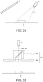
- FIG. 5 is a schematic diagram in which one portion of the illumination device 4 of the embodiment is enlarged.
- the illumination device 4 includes a plurality of illumination elements 41 which are disposed in a matrix shape.
- the illumination device 4 can light up each illumination element 41 independently.
- the irradiation patterns in the embodiment are determined by the illumination elements 41 to be lighted up among the plurality of illumination elements 41.
- white light is irradiated from each illumination clement 41, and the irradiation patterns refer to shading patterns on the light emission surface 40.
- the illumination device 4 can light up or light off each illumination element 41 independently.
- the illumination device 4 can also adjust light emission intensity of each illumination element 41.
- Each illumination element 41 includes, for example, a light emission region and a translucent region, and by making the light emission region emit light, it can be approximated as that the entire illumination element 41 emits light in terms of an illumination effect to the object W.
- the translucency can be kept by having the translucent region.
- reflection profile information 72 in the first specific example is described.
- the reflection profile information 72 is the information showing relationships between positions within the light emission surface 40 and degrees of the light reflected at the attention sites A of the object W and incident to the camera 8 with respect to the light irradiated to the object W from the aforementioned positions.
- FIG. 6 is a diagram showing one example of a process for obtaining the reflection profile information 72 in the first specific example.
- the process for obtaining the reflection profile information 72 includes a process Ph1 for obtaining the data, a process Ph2 for extracting the data, and a process Ph3 for generating the reflection profile information 72 from the extracted data.
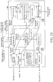
- FIG. 7 is a diagram for describing an obtainment method of data. Besides, in FIG. 7 , an illustration of the camera 8 is omitted.
- the illumination device 4 can make only the partial regions 43 set within the light emission surface 40 emit light.
- the light emission surface 40 consists of an aggregation of all the illumination elements 41.
- the partial regions 43 consist of one or a plurality of illumination elements 41. That is, the partial regions 43 are a partial aggregation with respect to the aggregation of all the illumination elements 41.
- the illumination device 4 can light up each of the plurality of illumination elements 41 independently, and thus the illumination device 4 can make only the set partial regions 43 emit light by lighting up all the illumination elements 41 included within the partial regions 43 set on the light emission surface 40.
- the illumination device 4 may make all the illumination elements 41 included in the partial regions 43 lighted up with the same light emission intensity or with light emission intensities different from one another.
- the control device 100 controls the illumination device 4 to light up each of plural types of partial regions 43 set on the light emission surface 40.
- Each of the plural types of partial regions 43 is different at least in positions within the light emission surface 40.
- the positions of the partial regions 43 within the light emission surface 40 mean centres of the partial regions 43.
- a size of each of the plural types of partial regions 43 may be the same as each other or be different from each other.
- a shape of each of the plural types of partial regions 43 may be the same as each other or be different from each other.
- one portion of one partial region 43 may be a region in common with one portion of an adjacent partial region 43.
- each of the plural types of partial regions 43 are the same as one another, and each partial region 43 does not overlap with another partial region 43.
- Sizes of the partial regions 43 may be the sizes that can ensure a light amount to a degree at which the camera 8 can capture images from which at least one portion of the object W can be recognized when the partial regions 43 are made to emit light.
- the irradiation patterns refer to the shading patterns of the light emission surface 40
- making one partial region 43 emit light can be referred to as making the light emission surface 40 emit light with one irradiation pattern.
- each of the plural types of partial regions 43 can be referred to as an irradiation pattern different from one another.
- the control device 100 sets the partial regions 43 in each of the position (X 1 , Y 1 ) to the position (X m , Y n ) on the light emission surface 40 and makes a total of m ⁇ n partial regions 43 emit light independently.
- the control device 100 controls the camera 8 to image in synchronization with the light emission of each of the plural types of partial regions 43, and obtains a total of m ⁇ n input images D.
- an X direction on the light emission surface 40 is described as a movement direction of the object W in FIG. 3
- a Y direction is described as a direction orthogonal to the X direction and an irradiation direction.
- the input images D (X, Y) mean the images captured and obtained in a state when the partial regions 43 set in the positions (X, Y) are made to emit light.
- a position of each of the camera 8, the illumination device 4 and the object W is fixed. That is, the imaging conditions at the time when the input image D (X 1 , Y 1 ) to the input image D (X m , Y n ) are captured are different at least in the positions on the light emission surface 40 which emits light.
- FIG. 8 is a diagram for describing an extraction method of the data.
- the control device 100 extracts partial images M corresponding to the attention sites A of the object W from each of the input image D (X 1 , Y 1 ) to the input image D (X m , Y n ).
- the partial images M corresponding to the attention sites A of the object W are the partial regions which are extracted to include attention positions a (x, y) corresponding to the attention sites A of the object W within the input images D.
- All the input image D (X 1 , Y 1 ) to the input image D (X m , Y n ) are obtained by being captured in the same imaging visual field 81. Therefore, camera coordinate positions (x, y) of the partial images M corresponding to the attention sites A are in common in each of the input image D (X 1 , Y 1 ) to the input image D (X m , Y n ).
- the partial images M may be data configured by one pixel or be data configured by a plurality of pixels, and may include at least pixels of the attention positions a (x, y) corresponding to the attention sites A. Besides, the attention sites A may show certain prescribed positions or show predefined ranges.
- the control device 100 extracts the partial images M of the attention positions a (x, y) within a camera coordinate corresponding to the attention sites A from each of the input images D (X 1 , Y 1 ) to D (X m , Y n ), and obtains the partial image M (X 1 , Y 1
- x r , y r ) means the positions (X, Y) of the light emission surface 40 which emits light when the input images D which are extraction origins are captured.
- x r , y r ) means the attention positions a (x, y) within the input images D which are targets at the time of extracting the partial images M. That is, the partial images M (X, Y
- FIG. 9 is a diagram for describing a generation method of the reflection profile information 72.
- the control device 100 extracts feature amounts p from each of the partial image M (X 1 , Y 1
- the feature amounts p are values showing intensities of the light which are reflected at the attention sites A and incident to the camera 8 among the light which are incident to the attention sites A from the partial regions 43 set on the light emission surface 40, and include, for example, luminance values, or values obtained by standardizing the luminance values.
- the feature amounts p can also be information obtained after performing a pre-processing such as a spatial filtering or the like on the partial images M.
- X, Y) mean feature amounts extracted from the partial images M (X, Y
- X m , Y n ) is the reflection profile information 72. That is, the control device 100 generates the reflection profile information 72 by extracting the feature amount p (x, y
- X, Y) means the attention positions a (x, y) which are positions of the attention sites A within the imaging visual field 81.
- X, Y) means which positions (X, Y) on the light emission surface 40 are made to emit light to obtain the feature amounts p. That is, the feature amounts p (x, y
- the input images D (X, Y) are generated by the light incident to the camera 8 among the light which are irradiated from the partial regions 43 set in the positions (X, Y) on the light emission surface 40 and reflected at the attention sites A.
- the feature amounts p (x, Y) are values showing intensities of the light that reflected at the attention sites A and incident to the camera 8 among the light incident to the object W from the positions (X, Y) on the light emission surface 40. That is, the feature amounts p (x, Y) can be referred to as the information showing degrees of the light reflected at the attention sites A and incident to the camera 8 with respect to the light irradiated from the positions (X, Y).
- the reflection profile information 72 which is configured by the aggregation of the feature amount p (x, y
- FIG. 10 is a diagram showing one example of an output method of the reflection profile information 72.
- the control device 100 outputs a mapping image 542, in which the feature amounts p are mapped in an XY coordinate which is the coordinate system on the light emission surface 40, as the reflection profile information 72.
- the mapping image 542 is an image in which gray values 56 shown by the shading degrees corresponding to a magnitude of the feature amounts p are mapped in the XY coordinate.
- X 1 , Y 1 ) is mapped in a position (X 1 , Y 1 ) of the XY coordinate.
- the control device 100 converts each of the feature amount p (x, y
- the control device 100 generates the mapping image 542 by mapping each of the gray values 56 (x, y
- the gray values 56 are shown as images having a predefined area (the same applies to FIG. 11 ).
- the control device 100 outputs the reflection profile information 72 by displaying the mapping image 542 on the display portion 102.
- an output destination of the mapping image 542 is, but not limited to, for example, the display portion 102 connected to the control device 100, and can also be a printer, the PLC 200, or a portable terminal or the like.
- the feature amounts p are values showing intensities of the light reflected at the attention sites A and incident to the camera 8 among the light incident to the object W from the partial regions 43 set on the light emission surface 40. Therefore, the user can intuitively grasp, based on the mapping image 542, effects of the light irradiated from which irradiation position are strong when the images of the attention sites A are generated. For example, in a case that the images have darker colours when the feature amounts p are greater, the user can intuitively grasp from the mapping image 542 that, images including great feature amounts can be obtained by making the partial regions 43 which are set in the positions mapped by the images with darker colours emit light.
- the reflection profile information 72 is the information showing the relationships between the positions within the light emission surface 40 and the degrees of the light reflected at the attention sites A of the object W and incident to the camera 8 with respect to the light irradiated to the object W from the positions. Therefore, when the illumination conditions at the time of performing an image measurement are set, it can be predicted from the reflection profile information 72 which direction it is from which the light is incident to the attention sites A to obtain images suitable as the images used in the image measurement. In the following, description is made on a setting method of the illumination conditions using the reflection profile information 72 when the image measurement of the attention sites A is performed.
- FIG. 11 is a diagram showing one example of a user interface screen 600 during the setting.
- the user interface screen 600 shown in FIG. 11 is displayed in the display portion 102 by selecting an illumination setting tab 610.
- the tabs relating to other settings such as a "camera setting” tab for setting the camera 8, an "image processing setting” tab for setting the processing contents executed on the obtained images and so on may also be arranged.
- the user interface screen 600 includes an image display region 620, an edition region 630, a tool selection region 640, a display selection region 650 and an instruction region 660.
- the image display region 620 is a region which displays the image of the imaging visual field 81 captured by the camera 8.
- the user operates a mouse or the like, which is one example of the input portion 104, and selects the attention position a corresponding to the attention site A from the image displayed on the image display region 620.
- a region including the selected attention site A is displayed on the image display region 620 as a selection region 622.
- the attention site A may show a certain prescribed position or show a predefined range. That is, the attention position a corresponding to the attention site A may be configured by one pixel or be configured by a plurality of pixels.
- the selection region 622 is desirable to be a shape corresponding to a range of the attention position a. For example, when the attention position a is configured by one pixel, the selection region 622 is shown by a point, and when the attention position a is configured by a plurality of pixels, the selection region 622 is shown by a region of a predefined range.
- the edition region 630 is a region in which the mapping image 542 of the attention position a which is selected by an operation to the image display region 620 can be displayed, and is a region for setting the illumination conditions based on the displayed mapping image 542. That is, the display which shows the position (the attention position a) of the attention site A within the imaging visual field 81 and the mapping image 542 of the attention site A which is selected by the operation to the image display region 620 are displayed on the same user interface screen 600. Therefore, the user can easily grasp the mapping image 542 being displayed is the mapping image 542 with respect to the attention site A in which position (attention position a) within the imaging visual field 81.
- the coordinate system of the mapping image 542 is a coordinate system showing the light emission surface 40. That is, the coordinate system of the edition region 630 is also the coordinate system showing the light emission surface 40.
- the user can operate the input portion 104 to use a square tool 642, a sectorial tool 644, a triangular tool 646 or the like displayed in the tool selection region 640 to plot the region (the light emission region) which emits light within the edition region 630 displayed in the coordinate system showing the light emission surface 40.
- a light emission region 632 is plotted in the mapping image 542.
- the received light emission region is reflected in the mapping image 542.
- the designated light emission range means designating the light emission intensities for every position on the light emission surface 40.
- FIG. 11 an example is shown in which the designation of whether the light is emitted is received as the light emission intensities, and the light emission intensities can also be adjusted.
- the mapping images 542 By reflecting the designated light emission range on the mapping images 542, when the images of the attention positions a are obtained by the irradiation patterns in which the designated light emission range is lighted up, the light emission range can be designated while confirming the images showing what kind of feature amounts p are obtained.
- the image display region 620 and the edition region 630 are regions adjacent to one another. That is, the image of the imaging visual field 81 and the image of the mapping image 542 are displayed side by side. Therefore, the user can easily grasp the mapping image 542 is the mapping image 542 with respect to the attention site A of which position (attention position a) within the imaging visual field 81.
- the tool selection region 640 is a region for selecting the tool (the square tool 642, the sectorial tool 644 and the triangular tool 646) used for plotting the light emission region 632.
- the user can select the tool by moving the cursor to the tool to be used for plotting the light emission region 632 and clicking.
- the user can use the selected tool to designate the light emission range.
- the display selection region 650 is a region for determining contents display in the edition region 630.
- a mapping display tab 652 and an irradiation pattern display tab 654 are arranged. If the mapping display tab 652 is selected, the mapping image 542 of the attention site A which is selected in the image display region 620 is displayed in the edition region 630. If the irradiation pattern display tab 654 is selected, the irradiation pattern which is set for the attention site A selected in the image display region 620 is displayed in the edition region 630.
- the selection may be performed to both of the mapping display tab 652 and the irradiation pattern display tab 654, and if both are selected, the mapping image 542 and an image (the light emission region 632) which shows the region of a registered light emission range are overlapped and displayed in the edition region 630.
- the instruction region 660 includes an obtainment button 662, an imaging button 664. a register button 666 and a back button 668.
- the obtainment button 662 is a button for making each of the plural types of partial regions 43 emit light and generating the reflection profile information 72 by the above-described method. If it is detected that the obtainment button 662 is selected, the control device 100 executes the processing for generating the reflection profile information 72. In addition, when the obtainment button 662 is selected, the attention site A (the attention position a) is selected in the image display region 620, and when the mapping display tab 652 is selected in the display selection region 650, the control device 100 updates the display of the edition region 630 to the mapping image 542 for the attention site A which is selected.
- the imaging button 664 is a button for taking images in a state that the range within the light emission surface 40 set in the edition region 630 is made to emit light.
- the control device 100 instructs, based on the detection that the imaging button 664 is selected, the illumination device 4 to irradiate the light by the irradiation patterns which make the light emission region 632 displayed in the edition region 630 emit light, and instructs the camera 8 to take images under the irradiation patterns.
- the register button 666 is a tab for registering the irradiation patterns which make the light emission region 632 displayed in the edition region 630 emit light as the irradiation patterns of the attention site A (the attention position a shown by the selection region 622) selected in the image display region 620.
- the back button 668 is a button for cancelling without registering the irradiation patterns displayed in the edition region 630. When the back button 668 is selected, for example, the user interface screen 600 is deleted from the display portion 102.
- the user can set the attention position a within the imaging visual field 81, and set the illumination conditions corresponding to reflection characteristics of the attention site A corresponding to the selected attention position a.
- the user can recognize whether images including or not including the feature amounts p are obtained, and can set the illumination conditions for obtaining the images including or not including the feature amounts p via the input portion 104.
- the control device 100 associates the irradiation patterns which are the set illumination conditions with the attention positions a of the attention sites A within the imaging visual field 81 for storage.
- control device 100 may also associates the irradiation patterns which are the set illumination conditions with the position of the attention sites A within the object W for storage, and prescribe the position (the attention positions a) within the imaging visual field 81 from an arrangement situation of the object W within the imaging visual field 81 and the position of the attention sites A within the object W.
- the user can set a plurality of attention positions a within the imaging visual field 81 and set irradiation patterns L which are the illumination conditions according to the reflection characteristics of the attention sites A corresponding to each of the plurality of attention positions a.
- irradiation patterns L which are the illumination conditions according to the reflection characteristics of the attention sites A corresponding to each of the plurality of attention positions a.
- FIG. 12 is a diagram for describing one example of the generation method of the inspection image 51.
- the control device 100 controls the illumination device 4 to sequentially change the irradiation patterns of the light irradiate from the illumination device 4, and controls the camera 8 to image the object W under each irradiation pattern.
- the control device 100 performs the appearance inspections of the object W based on the inspection image 51 generated from the plurality of images which are captured in each of the plurality of irradiation patterns.
- the irradiation patterns L are set for each attention position a (x, y) within the imaging visual field 81 of the camera 8.
- (x, y) means coordinate values of the attention positions a within the imaging visual field 81.
- the inspection image 51 used in the appearance inspections is generated from a plurality of original images 52 which are captured and obtained respectively under each irradiation pattern L.
- the images of the attention positions a within the inspection image 51 are generated from the original images 52 which are captured under the irradiation patterns L set in association with the attention positions a.
- the attention position a 1 (x 1 , y 1 ) to the attention position a n (x p , y q ) are set as the attention positions a within the imaging visual field 81.
- the irradiation patterns L are set for every attention position a.
- the control device 100 obtains the original image 52 (x 1 , y 1 ) to the original image 52 (x p , y q ) which are captured under the irradiation pattern L 1 to the irradiation pattern L n .
- the control device 100 generates the inspection image 51 from the plurality of original image 52 (x 1 , y 1 ) to the original image 52 (x p , y q ) that are obtained.
- the control device 100 generates an image of the attention position al (x 1 , y 1 ) within the inspection image 51 based on an extraction image 53 (x 1 , y 1 ) which includes the position (x 1 , y 1 ) within the original image 52 (x 1 , y 1 ).
- control device 100 generates an image of the attention position a 2 (x 2 , y 1 ) within the inspection image 51 based on the extraction image 53 (x 2 , y 1 ), and generates an image of the attention position a n (x p , y q ) within the inspection image 51 based on the extraction image 53 (x p , y q ).
- the inspection image 51 is generated from the extraction image 53 (x 1 , y 1 ) to the extraction image 53 (x p , y q ).
- Pixels included in the extraction images 53 may be one pixel or a plurality of pixels. Ranges of the extraction images 53 are set corresponding to distances between the attention positions a and the attention positions adjacent to the attention positions a, and are set in a manner that one inspection image 51 is generated from the extraction image 53 (x 1 , y 1 ) to the extraction image 53 (x p , y q ). Besides, the ranges of the extraction images 53 can also be set so that the extraction images 53 overlap with one another. On this occasion, pixel information of overlapped parts is generated based on more than two overlapped extraction images 53.
- the irradiation patterns L set for the attention positions a are set according to the reflection characteristics of the attention sites A of the object corresponding to the attention positions a. Therefore, the attention sites A can be measured based on the images captured under the illumination conditions suitable for the reflection characteristics of the attention sites A. In this way, images can be captured under the illumination conditions which are suitable for the reflection characteristics of each of a plurality of attention sites A on the object W, so that the image measurement with a high precision can be performed.
- FIG. 13 is a diagram schematically showing a function configuration of the control device 100.
- the control device 100 controls each configuration shown in FIG. 13 to set the irradiation patterns by executing the setting program 134.
- the control device 100 includes, for example, the light emission control portion 12, the imaging control portion 14, a detection portion 11, an extraction portion 16 and the output portion 18.
- the detection portion 11 detects the designation of the position (x r , y r ) within the imaging visual field 80, which is input from the input portion 104. For example, if the obtainment button 662 shown in FIG. 10 is operated, the detection portion 11 judges whether the input images D, which are necessary for obtaining the mapping image 542, are saved in the main memory 120, and if not saved, the light emission control portion 12 and the imaging control portion 14 are notified of the fact that an obtainment instruction has been made to execute the process Ph1 for obtaining the input images D.
- the light emission control portion 12 and the imaging control portion 14 function as obtainment portions for executing the process Ph1.
- the light emission control portion 12 controls, according to the obtainment instruction, the illumination device 4 to make the plurality of partial regions 43 which is set on the light emission surface 40 sequentially emit light.
- the imaging control portion 14 controls the camera 8 to sequentially generate the images of the imaging visual field 81 corresponding to the sequential light emission of the partial regions 43.
- the imaging control portion 14 associates the input images D generated by the camera 8 with the positions (X, Y) on the light emission surface 40 of the partial regions 43 which emit light when the input images D are captured, and saves the association in the main memory 120 which is on kind of a storage portion.
- the detection portion 11 instructs the extraction portion 16 to extract the partial images M which are corresponding to the position (x r , y r ) input from the input portion 104 (an extraction instruction).
- the position (x r , y r ) input from the input portion 104 is a position of the attention position a within the imaging visual field 81, and is the position (x, y) of the selection region 622 within the image display region 620.
- the extraction portion 16 extracts, according to the extraction instruction, the partial images M which are corresponding to the positions of the camera coordinate (x, y) from each of the plurality of input images D saved in the main memory 120. If the partial images M are extracted, the extraction portion 16 instructs the output portion 18 to output the mapping image 542 for the designated attention position a (an output instruction).
- the output portion 18 outputs, according to the output instruction, the reflection profile information 72 as the mapping images 542, and in the reflection profile information 72, the feature amounts p shown by the partial images M is associated with the positions (X, Y) of the partial regions 43 which emit light when the input images D being extraction origins of the partial images M are generated.
- the output portion 18 displays the mapping image 542 on the display portion 102, wherein the mapping image 542 is mapped with the gray values 56 (x, y
- the control device 100 may further include a determination portion 13 that determines the irradiation patterns for every attention position a and stores the irradiation patterns in the hard disk 130 as inspection information 136. If it is detected that the register button 666 of FIG. 10 is operated, the detection portion 11 instructs the determination portion 13 to register the irradiation patterns (register instruction).
- the determination portion 13 associates, at a timing when the register button 666 is operated, the attention positions a (x, y) designated in the image display region 620 with the irradiation patterns L set in the edition region 630 for a determination and stores the association as the inspection information 136 in the hard disk 130.
- the control device 100 includes an imaging measurement portion 15 for performing the image measurement.
- the detection portion 11 detects that a signal (an inspection start signal) which shows that the object W is conveyed to the predefined inspection position has been notified from the PLC 200. If the inspection start signal is detected, the detection portion 11 instructs the imaging measurement portion 15 to start the image measurement (a measurement instruction).
- the imaging measurement portion 15 performs the image measurement in accordance with the inspection information 136 stored in the hard disk 130. Specifically, the imaging measurement portion 15 instructs the imaging control portion 14 in a manner that the irradiation patterns L is set in the light emission control portion 12 in accordance with the inspection information 136 and to generate the extraction images 53 of the positions (x, y) corresponding to the attention positions a which are corresponding to the set irradiation patterns L. Accordingly, the imaging measurement portion 15 obtains a plurality of extraction images 53, generates the inspection image 51 based on the obtained extraction images 53 and measures an appearance of the object W based on the generated inspection image 51.
- the inspection image 51 is generated from a plurality of extraction images 53, so that it can also be said that the imaging measurement portion 15 performs the image measurement of a region including the attention positions a based on the extraction images 53 of the attention positions a corresponding to the irradiation patterns L.
- An image measurement result that is obtained is transmitted to the PLC 200 or the like.
- FIG. 14 is a flowchart of the processing of outputting the reflection profile information 72 of the designated attention position a.
- the processing of outputting the reflection profile information 72 is a processing which is implemented by the CPU 110 developing the setting program 134 in the main memory and executing the setting program 134.
- the processing of outputting the reflection profile information 72 is executed every time the obtainment button 662 is operated.
- step S11 the CPU 110 judges whether the input images D are saved in the main memory 120. When it is judged that the input images D are not saved in the main memory 120 ("NO" in step S11), the CPU 110 switches the processing to step S12.
- step S12 the CPU 110 judges whether all the partial regions 43 are set on the light emission surface 40.
- All the partial regions 43 mean all of the plural types of partial regions 43 set in advance. For example, the CPU 110 judges whether each partial region 43 which is set in different positions on the light emission surface 40 is set to all the positions that are set.
- the plural types of partial regions 43 may be set in a manner that the range on the light emission surface 40 of the predefined range emits light.
- the predefined range is a range arbitrarily set according to a size of the object W, the imaging visual field 81 or the like.
- step S13 the partial regions 43 are set on the light emission surface 40 and the set partial regions 43 are caused to emit light.
- step S14 the CPU 110 makes the camera 8 generate the input images D.
- the CPU 110 repeats step S13 and step S14 until it is judged to be "YES" in step S12. Accordingly, the CPU 110 can make each of the plural types of partial regions 43 emit light, and can generate the input images D in synchronization with the light emission of each of the plural types of partial regions 43.
- step S11 When it is judged that the input images D are saved in the main memory 120 ("YES" in step S11), or it is judged that all the partial regions 43 are set on the light emission surface 40 ("YES" in step S12), the CPU 110 switches the processing to step S15.
- step S15 the CPU 110 extracts the partial images M which are corresponding to the designated attention positions a from each of a plurality of input images D.
- step S16 the CPU 110 outputs the reflection profile information 72 in which the feature amounts p shown by the partial images M are associated with the positions of the partial regions 43 which emit light when the input images D being the extraction origins of the partial images M are generated.
- the reflection profile information 72 in the first specific example is the information in association with the positions on the light emission surface 40.
- the reflection profile information 74 in the second specific example is different from the reflection profile information 70 in that the reflection profile information 74 is information in association with relative positions (i, j) with respect to the positions (the attention positions a) within the imaging visual field of the attention sites A.
- the imaging method of the input images D, the extraction method of the partial images M and the extraction method of the feature amounts p are in common with the reflection profile information 70, so that the description is partially omitted.
- the relative positions are described.
- the relative positions are represented by an ij coordinate.
- FIG. 15 is a diagram for describing the relative positions.
- the ij coordinate is a coordinate which takes the position on the light emission surface 40 having a correspondence relationship with the attention position a as a reference position.
- the reference position means, for example, an origin (0, 0).
- a relationship of a formula (1) is established between the attention position ar (x r , y r ) of the attention site Ar within the camera coordinate system and a corresponding position (X r , Y r ) on the light emission surface 40. Therefore, the corresponding position (X r , Y r ) on the light emission surface 40 can be obtained from the attention position ar.
- X r Y r A x r y r + B
- Coefficients A, B are calibration parameters, and can be calculated by calculation based on a position relationship between the camera 8 and the illumination device 4 after the positions of the camera 8 and the illumination device 4 are fixed, or obtained by performing a calibration operation.
- the formula (1) is one example, and the positions on the light emission surface 40 which are corresponding to the positions within the camera coordinate system can also be defined in advance without using the formula (1).
- the attention positions a correspond to the positions (x, y) within the imaging visual field 81, so that the correspondence relationships between the positions (X, Y) on the light emission surface 40 and the positions (x, y) within the imaging visual field 81 are obtained by calibration.
- the control device 100 sequentially sets the partial regions 43 to different positions on the light emission surface 40 and makes the partial regions 43 emit light, and controls the camera 8 to sequentially generate the images of the imaging visual field 81 corresponding to the sequential light emission.
- a reference object called a target plate for the calibration may be disposed to perform the calibration, or the object W which is an inspection target may be disposed to perform the calibration.
- the control device 100 extracts the luminance values from each of the plurality of pixels included in the plurality of images which is obtained corresponding to the sequential lighting up.
- the control device 100 compares the luminance values of the pixels positioned in (x, y) within the plurality of images, and prescribes the pixels which have the highest luminance values.
- the control device 100 associates the position (X, Y) where the partial regions 43 are set when the images corresponding to the prescribed pixels are obtained with the positions (x, y) of the pixels within the images.
- the control device 100 can obtain correspondence relationships between the camera coordinate system and the illumination coordinate system by performing the same processing to all the pixels within the obtained images. Calibration parameters may be calculated by making the correspondence relationships between the camera coordinate system and the illumination coordinate system linearly approximated. Besides, the processing described above is performed for every pixel, and the processing described above can also be performed for every plural pixels taking the plural pixels as one unit.
- the light irradiated from the positions (X, Y) on the light emission surface 40 corresponding to the attention positions a can be said to be the light having the highest light amount reflected at the attention positions a and incident to the camera 8 among the light incident to the attention positions a.
- FIG. 16 is diagram showing a generation method of the reflection profile information 74 in the second specific example. Besides, the obtainment methods of the input images D, the partial images M, and the feature amounts p which are used for generating the reflection profile information 74 are in common with the first specific example, so that the description is partially omitted.
- the range of the feature amounts p which are included in the reflection profile information 74 in the second specific example is set to a range shown in a formula (2). (Expression 2) ⁇ i
- the reflection profile information 74 of the attention position ar (x r , y r ) within the imaging visual field 81 is generated.
- the control device 100 generates the input images D included in the range shown in the formula (3), and extracts a partial image M of the attention position ar (x r , y r ) from each input image D.
- the control device 100 extracts the partial image M of the attention position ar (x r , y r ) from each of the input image D (X r -w, Y r -w) to the input image D (X r +w, Y r +w), and extracts the partial image M (X r -w, Y r -w
- the input image D (X r -w, Y r -w) to the input image D (X r +w, Y r +w) can also be obtained by extracting the input images D included in the range shown in the formula (3) from the input image D (X 1 , Y 1 ) to the input image D (X m , Y n ). (Expression 3) ⁇ X
- the range shown in the formula (3) is defined based on the formula (2).
- the input images D of the range shown in the formula (3) mean the input images D which arc obtained when the partial regions 43 set within the range shown in the formula (3) emit light.
- the control device 100 extracts the feature amounts p from each of the partial image M (X r -w, Y r -w
- X r +w, Y r +w) can be represented as feature amount p (a r
- -w, -w) can also be referred to as a value based on the light which are among the light incident to the attention site A r and incident from the position (-w, -w) within the ij coordinate taking the position (X r , Y r ) on the light emission surface 40 corresponding to the attention position a r (x r , y r ) as the reference position.
- the reflection profile information 74 is different from the reflection profile information 72 in the first specific example in that the reflection profile information 74 is represented not by the XY coordinate on the light emission surface 40, but by the ij coordinate taking the positions on the light emission surface 40 which have correspondence relationships with the attention positions a as the reference positions. Because the reflection profile information 74 is represented by the ij coordinate, the reflection profile information 74 which reflects changes of the position relationship between the light emission surface 40 and the attention sites A can be obtained. As a result, the reflection profile information 74 obtained for every attention site A can be compared with one another in the same dimension regardless of the position relationships between the light emission surface 40 and the attention sites A.
- the range of the feature amounts p included in the reflection profile information 74 is set to the range shown by the formula (2), so that the reflection profile information 74 obtained for every attention site A is the information in the range the same with one another.
- the control device 100 can directly compare the reflection profile information 74 obtained for every attention site A with one another.
- FIG. 17 is a diagram showing an example of outputting the reflection profile information 74 in the second specific example as a mapping image 544.
- the control device 100 maps the gray values 56, which are corresponding to the magnitude of the feature amounts p shown by each of the plural partial images M that are extracted, in the ij coordinate taking the position (X r , Y r ) as the origin.
- -w, -w) is mapped to (-w, - w) within the ij coordinate.
- the gray values 56 are shown as images with predefined areas (the same applies to FIG. 20 and FIG. 21(a) to FIG. 21(d) ).
- the example is shown in which the reflection profile information 70 is used in order to set different irradiation patterns L for each of the plurality of attention positions a set within the imaging visual field 81.
- the reflection profile information 74 in the second specific example is used for setting a reference irradiation pattern L 0 .
- the reference irradiation pattern L 0 is an irradiation pattern which is a reference used to determine the irradiation pattern L of every attention position a.
- a determination method of the irradiation pattern L of every attention position a using the reference irradiation pattern L 0 is described, and a setting method of the reference irradiation pattern L 0 is described.
- the control device 100 sets the irradiation patterns L by setting a light emission region shown by the reference irradiation pattern L 0 in the positions on the light emission surface 40, which have the correspondence relationships in advance with the attention positions a, when the extraction images 53 corresponding to the attention positions a are obtained.
- FIG. 18 is a diagram for describing the determination method of the irradiation pattern L of every attention position a using the reference irradiation pattern L 0 .
- the irradiation pattern L r is determined so that the irradiation pattern L 0 is made taking the position (X r , Y r ) on the light emission surface 40 corresponding to the attention position a r (x r , y r ) as a centre.
- the control device 100 can calculate the irradiation pattern L r from the attention position ar (x r , y r ), the reference irradiation pattern L 0 , the formula (1) and the formula (4).
- FIG. 19 is a diagram for describing a generation method of the inspection image 51 using the reference irradiation pattern L 0 .
- the positions (X, Y) on the light emission surface 40 corresponding to the attention positions a are set as reference positions to set the light emission range shown by the reference irradiation pattern L 0 , and the original images 52 are generated, and the images of the positions which are corresponding to the attention positions a on the inspection image 51 are generated based on the extraction images 53 extracted from the original images 52. That is, the light emission range shown by the reference irradiation pattern L 0 is also sequentially set in the different positions on the light emission surface 40 by sequentially changing the attention positions a.
- FIG. 20 is a diagram showing a user interface screen 700 at the time of setting the reference irradiation pattern L 0 .
- the user interface screen 700 is different in that the user interface screen 700 includes an edition region 730 in place of the edition region 630, and includes an imaging button 764 in place of the imaging button 664.
- mapping images 544 of the ij coordinate system are displayed in the edition region 730. If the register button 666 is operated, a light emission region 732 which is set in the edition region 730 is saved as the reference irradiation pattern L 0 .
- the imaging button 764 If the imaging button 764 is operated, the inspection image 51, which is captured and generated under the reference irradiation pattern L 0 shown by the light emission region 732 plotted within the edition region 730, is displayed in the image display region 620. Accordingly, the user can judge whether the required image is obtained by the reference irradiation pattern L 0 that is set.
- FIG. 21(a) to FIG. 21(d) are diagrams showing one example of a flow of setting the reference irradiation pattern L 0 .
- the object W shown in FIG. 21(a) to FIG. 21(d) is a metal with machining marks formed on a surface.
- the input images D are already obtained.
- FIG. 21(a) to FIG. 21(d) only the image display region 620 and the edition region 730 of the user interface screen 700 are representatively shown.
- Scratches to be detected in the image measurement in the attention site A 1 of the object W are set to be the scratches on which the machining marks which are not desired to be detected in the image measurement in the attention site A 2 are formed.
- the user operates the input portion 104 to select, based on the images of the object W displayed within an image display region 620, the attention position a 1 corresponding to the attention site A 1 . If the attention position a 1 is selected, as shown in FIG. 21(a) , the control device 100 displays the mapping image 544 corresponding to the attention position a 1 in the edition region 730.
- the user plots the region (the light emission region 732) which emits light within the edition region 730 displayed by the ij coordinate system.
- FIG. 21(a) to FIG. 21(d) a darker colour is shown when the magnitude shown by the feature amounts p is greater, and it is judged that there are scratches if the magnitude shown by the feature amounts p is great. Because the scratches to be detected are formed in the attention position a 1 , great feature amounts p are desirably extracted from the attention position a 1 in the image measurement. Therefore, if the user plots the light emission region 732 to include a part shown by a dark colour, the illumination condition under which the marks like the attention site A 1 is easily detected can be set. In FIG. 21 (b) , an example in which the user plots the light emission region 732 to include the part shown by the dark colour is shown.
- the irradiation patterns under which small feature amounts p are extracted are desirable. If the user operates the input portion 104 to select, based on the images of the object W displayed within the image display region 520, the attention position a 2 corresponding to the attention site A 2 in a state shown in FIG. 21(b) , a state shown in FIG. 21(c) is switched to.
- the light emission region 732 which is set to easily detect the scratches is plotted in the mapping image 544 corresponding to the attention position a 2 .
- the user adjusts, as shown in FIG. 21(d) , the light emission region 732 for the edition region 730 shown in FIG. 21(c) so as not to include the part shown by the dark colour.
- the user can set the illumination conditions under which those to be detected as scratches can be detect and those not to be detected are not detected in the image measurement.
- FIG. 22 is a diagram schematically showing a function configuration of the control device 100 in the second specific example.
- the control device 100 may include an extraction range determination portion 17 in addition to the function configuration shown in FIG. 13 .
- the extraction range determination portion 17 determines a range of extraction to create the mapping images 544 in the reference coordinate system (i, j) which takes the position (X r , Y r ) on the light emission surface 40 corresponding to a camera coordinate (x r , y r ) that is input as a reference position. Specifically, the extraction range determination portion 17 prescribes the position (X r , Y r ) on the light emission surface 40 corresponding to the camera coordinate (x r , y r ) based on corresponding information 138 showing correspondence relationships between camera coordinate positions and the positions on the light emission surface 40, which are stored in a storage portion such as the hard disk 130 or the like.
- the corresponding information 138 includes, for example, the calibration parameters.
- the extraction range determination portion 17 determines a range (X r -w ⁇ X ⁇ X r +w, Y r -w ⁇ Y ⁇ Y r +w) to be extracted with the prescribed position (X r , Y r ) as the reference position.
- the extraction portion 16 extracts the partial images M in the camera coordinate (x r , y r ) from each of the input images D included in the extraction range (X r -w ⁇ X ⁇ X r +w, Y r -w ⁇ Y ⁇ Y r +w).
- the extraction portion 16 instructs the output portion 18 to output the reflection profile information 74 with respect to the designated attention position a r (x r , y r ) as the mapping image 544 (output instruction).
- the output portion 18 outputs, according to the output instruction, the feature amounts p shown by the partial images M by associating the positions (X, Y) of the partial regions 43, which emit light when the input images D being the extraction origins of the partial images M are generated, with the relative positions (i, j).
- the output portion 18 outputs the reflection profile information 74 by displaying, in the display portion 102, the mapping images 544 in which the gray values 56 corresponding to the magnitude of the feature amounts p shown by the partial images M are mapped in the ij coordinate which takes the positions on the light emission surface 40 having the correspondence relationships with the attention positions a as the reference positions.
- the reference irradiation pattern L 0 set in the edition region 630 is stored as the inspection information 136 during the operation of the register button 666.
- the control device 100 may further include a calibration portion 19.
- the calibration portion 19 generates the corresponding information 138. If the detection portion 11 detects an instruction of calibration, an execution of calibration is instructed to the calibration portion 19.
- the calibration portion 19 instructs the light emission control portion 12 and the imaging control portion 14 to obtain the input images D, sets the positions on the light emission surface 40 corresponding to each pixel position (x, y) from the obtained input images D and stores the positions as the corresponding information 138 in the hard disk 130 or the like.
- the control device 100 is different in that the control device 100 includes an imaging measurement portion 15a in place of the imaging measurement portion 15.
- the imaging measurement portion 15a performs the image measurement in accordance with the inspection information 136 stored in the hard disk 130. Specifically, the imaging measurement portion 15a makes the light emission control portion 12 set a light emission range shown by the reference irradiation pattern L 0 in different positions (X, Y) on the light emission surface 40 in accordance with the inspection information 136, and instructs the imaging control portion 14 to generate extraction images 53 of the positions (x, y) within the camera coordinate corresponding to the positions (X, Y) on the light emission surface 40 to which the light emission range is set.
- the imaging measurement portion 15 obtains a plurality of extraction images 53, generates the inspection image 51 based on the obtained extraction image 53 and measures the appearance of the object W based on the inspection image 51 that is generated.
- the image measurement result that is obtained is transmitted to the PLC 200 or the like.
- FIG. 23 is a flowchart of the processing of outputting the reflection profile information 74 in the second specific example of the designated attention position a.
- the flowchart shown in FIG. 23 is different from the flowchart shown in FIG. 14 in that step S15-1 is arranged.
- step S15-1 the CPU 110 sets the extraction range.
- the CPU 110 designates a predefined range as the extraction range with the positions on the light emission surface 40 corresponding to the designated attention positions a as the reference position.
- step S15 the partial images M are extracted in accordance with the extraction range designated in step S15-1.
- the example in which the illumination device 4 is disposed between the camera 8 and the object W is shown.
- the position relationship among the illumination device 4, the camera 8 and the object W is not limited to be coaxial, and may be a position relationship in which the light from the illumination device 4 are irradiated to the object W and at least one portion of the object W is included in the imaging visual field 81 of the camera 8.
- FIG. 24 is a diagram showing a variation example of the position relationship among the illumination device 4, the camera 8 and the object W.
- the illumination device 4 may not be disposed on an optical axis of the camera 8.
- the illumination device 4 is not disposed on the optical axis of the camera 8, so that an illumination device without permeability can be adopted as the illumination device 4.
- a translucent organic EL lamp is mentioned as one example of the illumination device 4.
- the illumination device 4 when the illumination device 4 is disposed between the camera 8 and the object W, the illumination device 4 may have at least any one of a shape not blocking the visual field at least during the imaging and an optical characteristic not blocking the visual field.
- the illumination device 4 may be the illumination device 4 in which an opening is arranged in one portion, the illumination device 4 in which one portion is configured by a coaxial incident illumination, or the like.
- FIG. 25 is a diagram showing a variation example of the illumination device.
- one portion is configured by a coaxial incident illumination 410 and the other portion is configured by an illumination 420 without translucency.
- the reflection profile information 70 As an output method of the reflection profile information 70, a method of outputting the reflection profile information 70 in which the feature amounts p are mapped to the predefined coordinate system is exemplified.
- the reflection profile information 70 can also be output by an approximate formula or the like in which the relationships between the positions on the light emission surface 40 and the feature amounts p are expressed.
- mapping images are set as two-dimensional plane images, but the reflection profile information 70 can also be represented by three or more dimensions.
- a representation form can also be used in which the feature amounts p are plotted in a coordinate system which consists of a coordinate axis showing the magnitude of the feature amounts p in addition to the coordinate axes corresponding to the positions on the light emission surface 40.
- mapping images 544 are sequentially switched as one example of the mapping images 544 obtained for each of the plurality of attention positions, but the plurality of mapping images 544 can also be overlapped and displayed.
- each partial region 43 is set not to be overlapped with another partial region 43.
- each partial region 43 can also be set to be overlapped with another partial region 43 in one portion. For example, by setting each partial region 43 to be overlapped with another partial region 43, a light amount at the time of making one partial region 43 emit light can be ensured without reducing a resolution of the reflection profile information.
- the illumination device 4 can also make the partial regions 43 emit light in a manner that the light emission intensities of the illumination elements 41 increase from boundaries of the partial regions 43 towards centres.
- the shading pattern of the partial regions is in the form of Gaussian distribution. In this way, compared with an occasion when the partial regions 43 evenly emit light, the light amount at the time of making one partial region 43 emit light can be further increased without reducing the resolution of the reflection profile information.
- the attention sites A show the prescribed positions, and the attention positions a corresponding to the attention sites A are information showing one point.
- the attention sites A may also be information showing prescribed ranges, and on this occasion, the attention positions a may also be ranges a' showing certain ranges within the images corresponding to the prescribed ranges.
- the reflection profile information of the attention sites A may be generated, for example, based on the reflection profile information obtained for each of the plurality of attention positions a included in the range a.
- the reflection profile information of the attention sites A may be the information in which the reflection profile information obtained for each of the plurality of attention positions a is standardized, or be the information which is expressed by a representation form in which a plurality of mapping images obtained when each reflection profile information is mapped to the ij coordinate is synthesized.
- the reflection profile information of the attention sites A can also be obtained by setting the ranges of the partial images M to the ranges corresponding to the ranges a.
- both the reflection profile information 72 in the first specific example and the reflection profile information 74 in the second specific example are the information which shows the relationships between the positions (X, Y) within the light emission surface 40 and the feature amounts p showing the degrees of the light reflected at the attention sites A of the object W and incident to the camera 8 with respect to the light irradiated to the object W from the positions (X, Y).
- the reflection profile information 70 becomes reference information for determining the illumination conditions. As a result, the setting of the illumination conditions becomes easy.
- the feature amounts p are obtained from luminance information within the input images D which are corresponding to the attention positions a within the imaging visual field 81.
- the reflection profile information 74 in the second specific example is the information associated with the relative positions (i, j) with respect to the positions (the attention positions a) within the imaging visual field of the attention sites A. Therefore, regardless of the position relationships between the light emission surface 40 and the attention sites A, the reflection profile information 74 obtained for every attention site A can be compared with one another in the same dimension.
- the control device 100 outputs the reflection profile information 74 to the ij coordinate system corresponding to the relative positions in a representation form of the mapping images 544 to which the feature amounts p are output. Therefore, because the reflection profile information 74 is represented by the same coordinate system regardless of the position relationships between the light emission surface 40 and the attention sites A, the reflection profile information 74 can be easily compared when compared for every attention site A.
- the attention positions a can be designated for the object W displayed in the image display region 620, and the mapping images 544 of the designated attention positions a are displayed in the edition region 630 or the edition region 730. Therefore, the user can easily grasp the mapping image 544 is related to which attention site A of the position within the imaging visual field 81.
- the user can set a plurality of attention positions a for the images of the object W which are displayed in the image display region 620, and can sequentially display the mapping images of the plurality of attention positions a that is set in the edition region. Accordingly, the mapping images for every attention position a can be compared easily.
- an example is shown in which one attention position a is selected and one mapping image 544 is displayed; however, a plurality of attention positions a may be simultaneously selected and the mapping images 544 corresponding to the plurality of attention positions a that is selected may be simultaneously or sequentially output.
- the irradiation patterns L are determined based on the reflection profile information 72. Therefore, the description property to the determined illumination condition can be ensured. Besides, similarly, the description property about the reference irradiation pattern L 0 determined based on the reflection profile information 74 can also be ensured.
- an overall compact image processing system 1 can be provided by using the illumination device 4 which can be disposed between the camera 8 and the object W as the illumination device. As a result, restriction on selection of applicable equipment can be avoided as far as possible.
- the embodiment includes disclosures as below.
- An image processing system including:
- the reflection profile information (74) is information which is obtained from each of the plurality of images (D) and which is based on luminance information (p) corresponding to attention points (a) in an imaging visual field within the images (D) and relative positions (i, j) of the partial regions (43), in which light is emitted when the images are captured with respect to the attention points (a).
- the image processing system wherein the output portion (18) outputs the reflection profile information (74) by a representation form (544) in which the information (56) corresponding to the luminance information is output to a coordinate system with two or more axes corresponding to the relative positions (i, j).
- the image processing system wherein the output portion (18) outputs the reflection profile information (74) by the representation form (544, 730), wherein the reflection profile information (74) corresponds to the attention points (a) that are determined based on the position information on images (620) which are designated by a user with respect to the images (620) of the imaging visual field (81) captured by the imaging portion (8).
- the image processing system according to configuration 3 or 4, wherein the output portion (18) simultaneously or sequentially outputs the reflection profile information (74) obtained for a plurality of attention points (a) within the imaging visual field (81) to the coordinate system (i, j) (730).
- the image processing system according to any one of configurations 1 to 5, further including a determination portion (13) which determines light emission conditions (L) of the light emission portion (4, 400) using the reflection profile information (72, 74).
- the image processing system according to any one of configurations 1 to 6, wherein the light emission portion (4, 400) is disposed between the imaging portion and the object, and has at least any one of a shape not blocking a visual field at the time of imaging and an optical characteristic not blocking the visual field.
- An image processing system including:
- the feature amounts (P) are values showing intensities of light reflected at the attention positions (a) and incident to the imaging portion among light incident to the attention positions (a) from the light unit partial regions (43) set on the emission surface (40).
- the image processing system further including a display portion (102), wherein the output portion (18) makes first images (542, 544) displayed in the display portion (102), and in the first images (542, 544), the positions (X, Y) of corresponding unit partial regions (43) on a first coordinate system (XY, ij) showing the light emission surface (40) are represented by a display form in accordance with the magnitude of the feature amounts (P) corresponding to the positions of the unit partial regions (43).
- the image processing system further including:
- the image processing system according to configuration 13 or 14, wherein the images (620) of the imaging visual field which are captured by the imaging portion (8) are displayed in the display portion (102); the input portion (104) receives user designations (622, 662) with respect to the images (620) of the imaging visual field which are displayed in the display portion (102); and the extraction portion (16) prescribes the attention positions (a) based on the user designations (622, 662) received by the input portion.
- the image processing system according to configuration 15, wherein the images (620) of the imaging visual field captured by the imaging portion and the first images (542, 544) are displayed side by side.
- the image processing system according to any one of configurations 13 to 16, wherein the determination portion (13) determines the irradiation patterns (L) in association with the designated attention positions (a), and an imaging measurement portion (15) is further included which performs the image measurement of the region including the attention positions (a) based on images (53) of the attention positions (a) corresponding to the irradiation patterns (L), which are generated by the imaging portion (8) when the light emission surface (40) emits light by the irradiation patterns (L) determined by the determination portion (13).
- the image processing system according to any one of configurations 13 to 16, wherein the light emission portion (4) makes the light emission region shown by the irradiation pattern (L 0 ) determined by the determination portion (13) sequentially set in different positions on the light emission surface(40) and emit light, and the imaging portion (8) sequentially generates the images (53) corresponding to the positions (x, y) within the imaging visual field, which have correspondence relationships with the positions on the light emission surface(40) which are set corresponding to the sequential light emission of the light emission region (8), and an imaging measurement portion (15a) is further included which performs the image measurement of the object based on a plurality of images generated by the imaging portion (8) corresponding to the sequential light emission of the light emission region.
- the image processing system according to configuration 18, wherein the extraction portion (16) extracts the partial images (M) from the input images (D), which are generated when the unit partial region emits light, and the unit partial region are set in a position included within a predefined range (X r -w ⁇ X ⁇ X r +w, Y r -w ⁇ Y ⁇ Y r +w) which takes the position (X r , Y r ) on the light emission surface having correspondence relationship with the designated attention position (a r ) as a reference position.
- a predefined range X r -w ⁇ X ⁇ X r +w, Y r -w ⁇ Y ⁇ Y r +w
Abstract
Description
- The disclosure relates to an image processing system, an image processing device and an image processing program.
- In an FA (Factory Automation) field and the like, an image processing technique is used in which an object is imaged under illumination by light from an illumination device and information about a work-piece is obtained from image data that is generated.
- As the illumination device used in an image processing technology field, various illumination devices are developed. For example, in Japanese laid-open No.
2015-232487 - (Patent Document 1) Japanese Laid-Open No.
2015-232487 - When the illumination device including a plurality of lamps with different illumination directions is used, there is a risk that when illumination conditions are determined, there are many patterns of selectable lamps and setting of the illumination conditions become complicated.
- The disclosure provides an image processing system, an image processing device and an image processing program, which facilitates the setting of the illumination conditions as described above.
- According to one example of the disclosure, an image processing system which has an imaging portion imaging an object and a light emission portion having a light emission surface directed toward the object is provided. The image processing system includes: a light emission control portion, which controls the light emission portion in a manner that each of plural types of partial regions set in advance in the light emission surface emits light; an imaging control portion, which controls the imaging portion to image in synchronization with light emission of each of the plural types of partial regions; and an output portion, which outputs reflection profile information, wherein the reflection profile information is obtained based on a plurality of images which are captured by the imaging portion in synchronization with the light emission of each of the plural types of partial regions, and the reflection profile information shows relationships between positions within the light emission surface and degrees of light reflected at attention sites of the object and incident to the imaging portion with respect to the light irradiated to the object from the positions.
- According to the disclosure, the reflection profile information which is a reference in determining illumination conditions is output, so that the setting of the illumination conditions becomes easy.
- In the above-described disclosure, the reflection profile information may be information which is obtained from each of the plurality of images and which is based on luminance information corresponding to attention points of an imaging visual field in the images and relative positions of the partial regions in which the light is emitted when the images are captured with respect to the attention points.
- According to the disclosure, the reflection profile information obtained for every attention point can be compared with one another in the same dimension regardless of the position relationships between the light emission surface and these attention points.
- In the above-described disclosure, the output portion may output the reflection profile information by a representation form in which the information corresponding to the luminance information is output to a coordinate system with two or more axes corresponding to the relative positions.
- According to the disclosure, regardless of position relationship between the
light emission surface 40 and the attention points, they are expressed in the same coordinate system, so that comparison can be made easily when comparing the reflection profile information for every attention point. - In the above-described disclosure, the output portion may output the reflection profile information by the representation form in which the information corresponding to the luminance information is input to the coordinate system with two or more axes corresponding to the relative positions, wherein the reflection profile information corresponds to the attention points that arc determined based on the position information on the images which are designated by a user with respect to the images of the imaging visual field imaged by the imaging portion.
- According to the disclosure, the user can easily designate these attention points.
- In the above-described disclosure, the output portion may simultaneously or sequentially output the reflection profile information obtained for a plurality of attention points within the imaging visual field to the coordinate system.
- According to the disclosure, the reflection profile information of every attention point is simultaneously or sequentially output to the same coordinate system, so that it is easy to compare the reflection profile information of every attention point.
- In the above-described disclosure, the image processing system may further include a determination portion which determines light emission conditions of the light emission portion using the reflection profile information.
- According to the disclosure, the light emission conditions of the light emission portion are determined based on the reflection profile information, so that a description property to the light emission conditions that are determined can be ensured.
- In the above-described disclosure, the light emission portion may be disposed between the imaging portion and the object, and have at least any one of a shape not blocking a visual field at the time of imaging and an optical characteristic not blocking the visual field.
- According to the disclosure, by disposing the light emission portion between the imaging portion and the object, compared with an occasion that the light emission portion is not disposed between the imaging portion and the object, an overall compact image processing system can be provided. As a result, selection of applicable equipment can be avoided from being restricted as much as possible.
- According to another example of the disclosure, an image processing device which controls an imaging portion imaging an object and a light emission portion having a light emission surface directed toward the object to perform an image processing is provided. The image processing device includes: a light emission control portion, which controls the light emission portion in a manner that each of plural types of partial regions set in advance in the light emission surface emits light; an imaging control portion, which controls the imaging portion to image in synchronization with light emission of each of the plural types of partial regions; and an output portion, which outputs reflection profile information, wherein the reflection profile information is obtained based on a plurality of images which are captured by the imaging portion in synchronization with the light emission of each of the plural types of partial regions, and the reflection profile information shows relationships between positions within the light emission surface and degrees of light reflected at attention sites of the object and incident to the imaging portion with respect to the light irradiated to the object from the positions.
- According to the disclosure, the reflection profile information which is a reference in determining the illumination conditions is output, so that the setting of the illumination conditions becomes easy.
- According to another example of the disclosure, an image processing program which is executed in an image processing device is provided, and the image processing device controls an imaging portion imaging an object and a light emission portion having a light emission surface directed toward the object to perform an image processing. The image processing program includes: controlling the light emission portion in a manner that each of plural types of partial regions set in advance in the light emission surface emits light; controlling the imaging portion to image in synchronization with light emission of each of the plural types of partial regions; and outputting reflection profile information, wherein the reflection profile information is obtained based on a plurality of images which are captured by the imaging portion in synchronization with the light emission of each of the plural types of partial regions, and the reflection profile information shows relationships between positions within the light emission surface and degrees of light reflected at attention sites of the object and incident to the imaging portion with respect to the light irradiated to the object from the positions.
- According to the disclosure, the reflection profile information which is a reference in determining the illumination conditions is output, so that the setting of the illumination conditions becomes easy.
- The reflection profile information which is a reference in determining the illumination conditions is output, so that the setting of the illumination conditions becomes easy.
-
-
FIG. 1 is a diagram schematically showing an application scene of an image processing system of an embodiment. -
FIG. 2 is a diagram schematically showing reflection profile information. -
FIG. 3 is a schematic diagram showing one example of a production line in which the image processing system of the embodiment is applied. -
FIG. 4 is a schematic diagram showing a hardware configuration of a control device. -
FIG. 5 is a schematic diagram in which one portion of an illumination device of the embodiment is enlarged. -
FIG. 6 is a diagram showing one example of a process for obtaining reflection profile information in a first specific example. -
FIG. 7 is a diagram for describing an obtainment method of data. -
FIG. 8 is a diagram for describing an extraction method of the data. -
FIG. 9 is a diagram for describing a generation method of the reflection profile information. -
FIG. 10 is a diagram showing one example of an output method of the reflection profile information. -
FIG. 11 is a diagram showing one example of a user interface screen at the time of setting. -
FIG. 12 is a diagram for describing one example of a generation method of an inspection image. -
FIG. 13 is a diagram schematically showing a function configuration of the control device. -
FIG. 14 is a flowchart of processing of outputting the reflection profile information of a designated attention position. -
FIG. 15 is a diagram for describing relative positions. -
FIG. 16 is a diagram showing a generation method of reflection profile information in a second specific example. -
FIG. 17 is a diagram showing an example of outputting the reflection profile information in the second specific example as mapping images. -
FIG. 18 is a diagram for describing a determination method of an irradiation pattern of every attention position using a reference irradiation pattern. -
FIG. 19 is a diagram for describing a generation method of the inspection image using the reference irradiation pattern. -
FIG. 20 is a diagram showing a user interface screen at the time of setting the reference irradiation pattern. -
FIG. 21(a) to FIG. 21(d) are diagrams showing one example of a flow of setting the reference irradiation pattern. -
FIG. 22 is a diagram schematically showing a function configuration of the control device in the second specific example. -
FIG. 23 is a flowchart of processing of outputting the reflection profile information in the second specific example of the designated attention position. -
FIG. 24 is a diagram showing a variation example of a position relationship among the illumination device, a camera and an object. -
FIG. 25 is a diagram showing a variation example of the illumination device. - At first, one example of a scene in which the disclosure is applied is First, with reference to
FIG. 1 andFIG. 2 , an example of a scene to which the present invention is applied will be described.FIG. 1 is a diagram schematically showing an application scene of animage processing system 1 of an embodiment.FIG. 2 is a diagram schematically showingreflection profile information 70. - The
image processing system 1 of the embodiment includes acamera 8 which is one example of an imaging portion, anillumination device 4 which is one example of a light emission portion, and acontrol device 100 which controls processing executed in theimage processing system 1. In addition, thecontrol device 100 includes a lightemission control portion 12 which controls theillumination device 4, animaging control portion 14 which controls thecamera 8, and anoutput portion 18 which outputs the reflection profile information. As an example, the lightemission control portion 12, theimaging control portion 14 and theoutput portion 18 are arranged in thecontrol device 100 which has a structure in accordance with general-purpose computer architecture. - The
illumination device 4 has alight emission surface 40 directed toward an object W. Theillumination device 4 can make any region of thelight emission surface 40 emit light, and is made of an organic EL (Electro Luminescence) for example. - The light
emission control portion 12 controls theillumination device 4 so that each of plural types ofpartial regions 43 which are set on thelight emission surface 40 emits light. Each of the plural types ofpartial regions 43 at least has different positions within thelight emission surface 40. Sizes of each of the plural types ofpartial regions 43 may be the same as each other or be different from each other. In addition, shapes of each of the plural types ofpartial regions 43 may be the same as each other or be different from each other. In addition, one portion of onepartial region 43 may be a region in common with one portion of an adjacentpartial region 43. - The
imaging control portion 14 controls thecamera 8 in a manner that the object W is imaged in synchronization with light emission of each of the plural types ofpartial regions 43. Here, "the object W is imaged in synchronization" means that the object W is imaged every time the kind of thepartial regions 43 emitting light is changed. - The light
emission control portion 12 and theimaging control portion 14 control theillumination device 4 and thecamera 8 as described above, and thereby an input image D is generated for every partial region emitting light and a plurality of input images D are obtained. - The
output portion 18 outputs thereflection profile information 70 obtained based on the plurality of input images D. Thereflection profile information 70 is the information showing relationships between a position within thelight emission surface 40 and degrees of light reflected at attention sites A of the object W and incident to thecamera 8 with respect to light irradiated to the object W from the aforementioned positions. - Specifically, the
reflection profile information 70 is described with reference toFIG. 2 . In the example shown inFIG. 2 , one kind ofpartial region 43 is set in a position (X1, Y1) on thelight emission surface 40. An input image D (X1, Y1), which is obtained when thepartial region 43 set in the position (X1, Y1) emits a light, is generated by a light Lc which is resulted from a light Li that is irradiated from the position (X1, Y1) being reflected by the object W and incident to thecamera 8. Accordingly, a feature amount P1 is obtained from the input image D (X1, Y1), and the feature amount P1 is a degree of the light Lc that is reflected at the attention site A of the object W and incident to thecamera 8 with respect to the light Li that is irradiated from the position (X1, Y1) on thelight emission surface 40. Similarly, a feature amount P2 is obtained from an input image D (X2, Y2) which is obtained when apartial region 43 set in a position (X2, Y2) emits a light, and the feature amount P2 is a degree of a light Lc that is reflected at the attention site A of the object W and incident to thecamera 8 with respect to the light Li that is irradiated from the position (X2, Y2). - Relationships between positions (X, Y) on the
light emission surface 40 and feature amounts P are obtained from each of the plurality of input images D. That is, thereflection profile information 70 is an aggregation of information consisting of the positions (X, Y) on the light emission surface and the feature amounts P. In the example shown inFIG. 2 , the feature amount P1 to the feature amount PN are obtained for each of the position (X1, Y1) to the position (Xm, Yn) on thelight emission surface 40, and the aggregation of the feature amount P1 to the feature amount PN is called as thereflection profile information 70. - When the
reflection profile information 70 is obtained, a reference of how much light is incident to thecamera 8 can be known when the light is irradiated from any position on thelight emission surface 40 to the object W. Therefore, thereflection profile information 70 is a reference for determining irradiation conditions. As a result, setting of illumination conditions becomes easy. Furthermore, because the setting of the illumination conditions can be performed based on thereflection profile information 70, a description property to the set illumination conditions can be ensured. - Next, one example of the image processing system of the embodiment is described.
FIG. 3 is a schematic diagram showing one example of a production line in which theimage processing system 1 of the embodiment is applied. - As shown in
FIG. 3 , theimage processing system 1 of the embodiment includes thecamera 8 which images the object W continuously carried in, theillumination device 4 which illuminates the object W, and thecontrol device 100 which controls theillumination device 4 and thecamera 8. - The
camera 8 includes an optical system such as a lens, an aperture or the like and a photoelectric converter such as a CCD (Charge Coupled Device) image sensor, a CMOS (Complementary Metal Oxide Semiconductor) image sensor or the like as main configuration elements. The photoelectric converter is a device which converts light included in an imagingvisual field 81 of thecamera 8 into image signals. - The
illumination device 4 irradiates light to the object W disposed on astage 300. Irradiation patterns of the light which are irradiated from thelight emission surface 40 can be arbitrarily changed according to the irradiation patterns instructed from thecontrol device 100. - The
illumination device 4 has translucency and is typically a translucent organic EL lamp. When a side where thecamera 8 is disposed is set as an upper side and a side where the object W is disposed is set as a lower side with a position where theillumination device 4 is disposed as a basis, theillumination device 4 may have translucency to a degree that thecamera 8 can image, via theillumination device 4, an object which is positioned lower than theillumination device 4. - The object W, which is an inspection subject, is moved by the
movable stage 300 to an inspection position where thecamera 8 and theillumination device 4 are fixed. Thestage 300 is controlled by a PLC 200 (Programmable Logic Controller). ThePLC 200 controls thestage 300 in a manner that when the object W is conveyed to the inspection position, thestage 300 stops instantly until an appearance inspection by theimage processing system 1 is completed. At this moment, thecontrol device 100 irradiates the light to the object W by theillumination device 4 and images the object W by thecamera 8. Thecontrol device 100 controls theillumination device 4 to change the irradiation pattern of the light irradiated from theillumination device 4, and controls thecamera 8 to image the object W by thecamera 8 every time the irradiation pattern of the light is changed. Thecontrol device 100 inspects an appearance of the object W by using plural pieces of captured images that are obtained as above. In addition, thecontrol device 100 outputs an inspection result to thePLC 200 when the appearance inspection is completed. ThePLC 200 makes the next object W be conveyed to the inspection position based on the output of the inspection result from thecontrol device 100. - The
control device 100 is electrically connected to adisplay portion 102 and aninput portion 104. Thedisplay portion 102 typically consists of a liquid crystal display and displays setting contents to the user for example. Theinput portion 104 typically consists of a mouse and functions for inputting information relating to various settings. For example, the user can input setting information relating to settings of inspection conditions by operating theinput portion 104 based on the information displayed in thedisplay portion 102. Besides, theinput portion 104 is configured by the mouse, and can also be configured by a touch panel, a keyboard or a combination thereof. -
FIG. 4 is a schematic diagram showing a hardware configuration of thecontrol device 100. Thecontrol device 100 includes a CPU (Central Processing Unit) 110, amain memory 120, ahard disk 130. a camera interface (I/F) 180, an illumination I/F 140, adisplay controller 172, an input I/F 174, a communication I/F 150, an external memory I/F 160 and anoptical drive 164. Each of these portions is connected to one another via abus 190 so that they are capable of data communication. - The
CPU 110 develops a program (a code), which includes animage processing program 132 and asetting program 134 installed on thehard disk 130, in themain memory 120 and executes these programs in a predefined order, thereby performing various calculations. Themain memory 120 is typically a volatile storage device such as a DRAM (Dynamic Random Access Memory) or the like. - The
hard disk 130 is an internal memory included in thecontrol device 100 and is a non-volatile storage device. Thehard disk 130 includesinspection information 136 relating to the inspection conditions in addition to theimage processing program 132 and thesetting program 134. Besides, in addition to thehard disk 130 or in place of thehard disk 130, a semiconductor storage device such as a flash memory or the like can also be adopted. - The camera I/
F 180 mediates data transmission between theCPU 110 and thecamera 8. That is, the camera I/F 180 is connected to thecamera 8 which generates the images. In addition, the camera I/F 180 gives commands of controlling imaging actions in theconnected camera 8 according to internal commands from theCPU 110. - The illumination I/
F 140 mediates the data transmission between theCPU 110 and theillumination device 4. That is, the illumination I/F 140 is connected to theillumination device 4. In addition, the illumination I/F 140 transmits, according to internal commands from theCPU 110, commands about the irradiation patterns to theconnected illumination device 4. Theillumination device 4 irradiates the light with the irradiation patterns based on the received commands. Besides, theillumination device 4 may be connected to thecontrol device 100 via thecamera 8. In addition, thecamera 8 may be connected to thecontrol device 100 via theillumination device 4. - The
display controller 172 is connected to thedisplay portion 102 and notifies the user of a processing result or the like in theCPU 110. That is, thedisplay controller 172 is connected to thedisplay portion 102 and controls display in thedisplay portion 102. - The input I/
F 174 is connected to theinput portion 104 and mediates the data transmission between theCPU 110 and theinput portion 104. That is, the input I/F 174 receives operation commands given by the user operating theinput portion 104. The operation commands include, for example, operation commands for setting the inspection conditions. - The communication I/
F 150 exchanges various data between thePLC 200 and theCPU 110. Besides, the communication I/F 150 can also exchange data between a server and theCPU 110. The communication I/F 150 includes hardware corresponding to a network for exchanging various data with thePLC 200. - The external memory I/
F 160 is connected to anexternal memory 6 and performs processing of reading/writing of data into theexternal memory 6. Theexternal memory 6 is detachable to thecontrol device 100 and is typically a non-volatile storage device such as a USB (Universal Serial Bus) memory, a memory card or the like. In addition, various programs such as theimage processing program 132 or the like are not required to be saved in thehard disk 130, and can also be saved in a server which is communicable with thecontrol device 100, theexternal memory 6 which can be directly connected to thecontrol device 100, or anoptical disk 164A. For example, the various programs which are executed in thecontrol device 100 and various parameters used in the various programs are circulated in a state of being stored in theexternal memory 6, and the external memory I/F 160 reads out the various program and the various parameters from theexternal memory 6. Elsewise, the programs or the parameters which are downloaded from the server or the like which is communicably connected to thecontrol device 100 may be installed on thecontrol device 100. In addition, thecontrol device 100 can also install the programs or the parameters on thecontrol device 100 from the optical disk 164Athrough theoptical drive 164. - The
optical drive 164 reads out from theoptical disk 164A or the like the various programs stored therein and installs the various programs on thehard disk 130. - Besides, the
image processing program 132 and thesetting program 134 of the embodiment can also be provided by being incorporated into one portion of other programs. In addition, alternatively, part of or all of the functions provided by the execution of theimage processing program 132 can also be implemented as a dedicated hardware circuit. -
FIG. 5 is a schematic diagram in which one portion of theillumination device 4 of the embodiment is enlarged. Theillumination device 4 includes a plurality ofillumination elements 41 which are disposed in a matrix shape. Theillumination device 4 can light up eachillumination element 41 independently. The irradiation patterns in the embodiment are determined by theillumination elements 41 to be lighted up among the plurality ofillumination elements 41. In addition, in the embodiment, it is described that white light is irradiated from eachillumination clement 41, and the irradiation patterns refer to shading patterns on thelight emission surface 40. In addition, in the embodiment, theillumination device 4 can light up or light off eachillumination element 41 independently. Besides, theillumination device 4 can also adjust light emission intensity of eachillumination element 41. - Each
illumination element 41 includes, for example, a light emission region and a translucent region, and by making the light emission region emit light, it can be approximated as that theentire illumination element 41 emits light in terms of an illumination effect to the object W. In addition, the translucency can be kept by having the translucent region. - In the following,
reflection profile information 72 in the first specific example is described. - The
reflection profile information 72 is the information showing relationships between positions within thelight emission surface 40 and degrees of the light reflected at the attention sites A of the object W and incident to thecamera 8 with respect to the light irradiated to the object W from the aforementioned positions.FIG. 6 is a diagram showing one example of a process for obtaining thereflection profile information 72 in the first specific example. The process for obtaining thereflection profile information 72 includes a process Ph1 for obtaining the data, a process Ph2 for extracting the data, and a process Ph3 for generating thereflection profile information 72 from the extracted data. -
FIG. 7 is a diagram for describing an obtainment method of data. Besides, inFIG. 7 , an illustration of thecamera 8 is omitted. Theillumination device 4 can make only thepartial regions 43 set within thelight emission surface 40 emit light. Thelight emission surface 40 consists of an aggregation of all theillumination elements 41. On the other hand, thepartial regions 43 consist of one or a plurality ofillumination elements 41. That is, thepartial regions 43 are a partial aggregation with respect to the aggregation of all theillumination elements 41. Theillumination device 4 can light up each of the plurality ofillumination elements 41 independently, and thus theillumination device 4 can make only the setpartial regions 43 emit light by lighting up all theillumination elements 41 included within thepartial regions 43 set on thelight emission surface 40. Besides, theillumination device 4 may make all theillumination elements 41 included in thepartial regions 43 lighted up with the same light emission intensity or with light emission intensities different from one another. - The
control device 100 controls theillumination device 4 to light up each of plural types ofpartial regions 43 set on thelight emission surface 40. Each of the plural types ofpartial regions 43 is different at least in positions within thelight emission surface 40. Here, the positions of thepartial regions 43 within thelight emission surface 40 mean centres of thepartial regions 43. A size of each of the plural types ofpartial regions 43 may be the same as each other or be different from each other. In addition, a shape of each of the plural types ofpartial regions 43 may be the same as each other or be different from each other. In addition, one portion of onepartial region 43 may be a region in common with one portion of an adjacentpartial region 43. In the embodiment, the shape and the size of each of the plural types ofpartial regions 43 are the same as one another, and eachpartial region 43 does not overlap with anotherpartial region 43. Sizes of thepartial regions 43 may be the sizes that can ensure a light amount to a degree at which thecamera 8 can capture images from which at least one portion of the object W can be recognized when thepartial regions 43 are made to emit light. Here, because the irradiation patterns refer to the shading patterns of thelight emission surface 40, making onepartial region 43 emit light can be referred to as making thelight emission surface 40 emit light with one irradiation pattern. In addition, each of the plural types ofpartial regions 43 can be referred to as an irradiation pattern different from one another. - In an example shown in
FIG. 7 , thecontrol device 100 sets thepartial regions 43 in each of the position (X1, Y1) to the position (Xm, Yn) on thelight emission surface 40 and makes a total of m×npartial regions 43 emit light independently. Thecontrol device 100 controls thecamera 8 to image in synchronization with the light emission of each of the plural types ofpartial regions 43, and obtains a total of m×n input images D. Here, in the embodiment, for the sake of convenience, an X direction on thelight emission surface 40 is described as a movement direction of the object W inFIG. 3 , and a Y direction is described as a direction orthogonal to the X direction and an irradiation direction. The input images D (X, Y) mean the images captured and obtained in a state when thepartial regions 43 set in the positions (X, Y) are made to emit light. Here, inFIG. 7 , a position of each of thecamera 8, theillumination device 4 and the object W is fixed. That is, the imaging conditions at the time when the input image D (X1, Y1) to the input image D (Xm, Yn) are captured are different at least in the positions on thelight emission surface 40 which emits light. -
FIG. 8 is a diagram for describing an extraction method of the data. Thecontrol device 100 extracts partial images M corresponding to the attention sites A of the object W from each of the input image D (X1, Y1) to the input image D (Xm, Yn). Here, the partial images M corresponding to the attention sites A of the object W are the partial regions which are extracted to include attention positions a (x, y) corresponding to the attention sites A of the object W within the input images D. All the input image D (X1, Y1) to the input image D (Xm, Yn) are obtained by being captured in the same imagingvisual field 81. Therefore, camera coordinate positions (x, y) of the partial images M corresponding to the attention sites A are in common in each of the input image D (X1, Y1) to the input image D (Xm, Yn). - The partial images M may be data configured by one pixel or be data configured by a plurality of pixels, and may include at least pixels of the attention positions a (x, y) corresponding to the attention sites A. Besides, the attention sites A may show certain prescribed positions or show predefined ranges.
- The
control device 100 extracts the partial images M of the attention positions a (x, y) within a camera coordinate corresponding to the attention sites A from each of the input images D (X1, Y1) to D (Xm, Yn), and obtains the partial image M (X1, Y1|x, y) to the partial images M (Xm, Yn|x, y). Here, the left of a vertical bar in brackets of the partial images M (X, Y|xr, yr) means the positions (X, Y) of thelight emission surface 40 which emits light when the input images D which are extraction origins are captured. The right of the vertical bar in the brackets of the partial images M (X, Y|xr, yr) means the attention positions a (x, y) within the input images D which are targets at the time of extracting the partial images M. That is, the partial images M (X, Y|xr, yr) mean the partial regions of the input images D (X, Y) which are extracted to include attention positions ar (xr, yr) within the input images D (X, Y). -
FIG. 9 is a diagram for describing a generation method of thereflection profile information 72. Thecontrol device 100 extracts feature amounts p from each of the partial image M (X1, Y1|x, y) to the partial image M (Xm, Yn|x, y). The feature amounts p are values showing intensities of the light which are reflected at the attention sites A and incident to thecamera 8 among the light which are incident to the attention sites A from thepartial regions 43 set on thelight emission surface 40, and include, for example, luminance values, or values obtained by standardizing the luminance values. In addition, the feature amounts p can also be information obtained after performing a pre-processing such as a spatial filtering or the like on the partial images M. Here, the feature amounts p (x, y|X, Y) mean feature amounts extracted from the partial images M (X, Y|x, y). - In the embodiment, an aggregation of the feature amount p (x, y|X1, Y1) to the feature amount p (x, y|Xm, Yn) is the
reflection profile information 72. That is, thecontrol device 100 generates thereflection profile information 72 by extracting the feature amount p (x, y|X1, Y1) to the feature amount p (x, y|Xm, Yn) from the partial image M (X1, Y1|x, y) to the partial image M (Xm, Yn|x, y). - Here, the left of the vertical bar in the brackets of the feature amounts p (x, y|X, Y) means the attention positions a (x, y) which are positions of the attention sites A within the imaging
visual field 81. The right of the vertical bar in the brackets of the feature amounts p (x, y|X, Y) means which positions (X, Y) on thelight emission surface 40 are made to emit light to obtain the feature amounts p. That is, the feature amounts p (x, y|X, Y) can also be referred to as the values based on the light incident from the positions (X, Y) on thelight emission surface 40, which are among the light incident to the attention sites A (the attention positions a (x, y)). - In addition, the input images D (X, Y) are generated by the light incident to the
camera 8 among the light which are irradiated from thepartial regions 43 set in the positions (X, Y) on thelight emission surface 40 and reflected at the attention sites A. In addition, the feature amounts p (x, Y) are values showing intensities of the light that reflected at the attention sites A and incident to thecamera 8 among the light incident to the object W from the positions (X, Y) on thelight emission surface 40. That is, the feature amounts p (x, Y) can be referred to as the information showing degrees of the light reflected at the attention sites A and incident to thecamera 8 with respect to the light irradiated from the positions (X, Y). Therefore, thereflection profile information 72, which is configured by the aggregation of the feature amount p (x, y|X1, Y1) to the feature amount p (x, y|Xm, Yn), is referred to as the information which shows the relationships between the positions (X, Y) within thelight emission surface 40 which are the irradiation positions, and the degrees of the light reflected at the attention sites A and incident to thecamera 8 with respect to the light irradiated from the irradiation positions. -
FIG. 10 is a diagram showing one example of an output method of thereflection profile information 72. In the example shown inFIG. 10 , thecontrol device 100 outputs amapping image 542, in which the feature amounts p are mapped in an XY coordinate which is the coordinate system on thelight emission surface 40, as thereflection profile information 72. Themapping image 542 is an image in whichgray values 56 shown by the shading degrees corresponding to a magnitude of the feature amounts p are mapped in the XY coordinate. For example, the gray value 56 (x, y|X1, Y1) corresponding to the magnitude of the feature amount p (x, y|X1, Y1) is mapped in a position (X1, Y1) of the XY coordinate. Thecontrol device 100 converts each of the feature amount p (x, y|X1, Y1) to the feature amount p (x, y|Xm, Yn) into thegray values 56 and obtains the gray value 56 (x, y|X1, Y1) to the gray value 56 (x, y|Xm, Yn). Thecontrol device 100 generates themapping image 542 by mapping each of the gray values 56 (x, y|X1, Y1) to 56 (x, y|Xm, Yn) in the XY coordinate. Besides, inFIG. 10 , in order to make it easy to understand how thegray values 56 are mapped, thegray values 56 are shown as images having a predefined area (the same applies toFIG. 11 ). - The
control device 100 outputs thereflection profile information 72 by displaying themapping image 542 on thedisplay portion 102. Besides, an output destination of themapping image 542 is, but not limited to, for example, thedisplay portion 102 connected to thecontrol device 100, and can also be a printer, thePLC 200, or a portable terminal or the like. - The feature amounts p are values showing intensities of the light reflected at the attention sites A and incident to the
camera 8 among the light incident to the object W from thepartial regions 43 set on thelight emission surface 40. Therefore, the user can intuitively grasp, based on themapping image 542, effects of the light irradiated from which irradiation position are strong when the images of the attention sites A are generated. For example, in a case that the images have darker colours when the feature amounts p are greater, the user can intuitively grasp from themapping image 542 that, images including great feature amounts can be obtained by making thepartial regions 43 which are set in the positions mapped by the images with darker colours emit light. - The
reflection profile information 72 is the information showing the relationships between the positions within thelight emission surface 40 and the degrees of the light reflected at the attention sites A of the object W and incident to thecamera 8 with respect to the light irradiated to the object W from the positions. Therefore, when the illumination conditions at the time of performing an image measurement are set, it can be predicted from thereflection profile information 72 which direction it is from which the light is incident to the attention sites A to obtain images suitable as the images used in the image measurement. In the following, description is made on a setting method of the illumination conditions using thereflection profile information 72 when the image measurement of the attention sites A is performed. -
FIG. 11 is a diagram showing one example of auser interface screen 600 during the setting. Theuser interface screen 600 shown inFIG. 11 is displayed in thedisplay portion 102 by selecting anillumination setting tab 610. Besides, inFIG. 10 , although tabs other than theillumination setting tab 610 are omitted, the tabs relating to other settings such as a "camera setting" tab for setting thecamera 8, an "image processing setting" tab for setting the processing contents executed on the obtained images and so on may also be arranged. - The
user interface screen 600 includes animage display region 620, anedition region 630, atool selection region 640, adisplay selection region 650 and aninstruction region 660. - The
image display region 620 is a region which displays the image of the imagingvisual field 81 captured by thecamera 8. The user operates a mouse or the like, which is one example of theinput portion 104, and selects the attention position a corresponding to the attention site A from the image displayed on theimage display region 620. InFIG. 11 , a region including the selected attention site A is displayed on theimage display region 620 as aselection region 622. Besides, the attention site A may show a certain prescribed position or show a predefined range. That is, the attention position a corresponding to the attention site A may be configured by one pixel or be configured by a plurality of pixels. Besides, theselection region 622 is desirable to be a shape corresponding to a range of the attention position a. For example, when the attention position a is configured by one pixel, theselection region 622 is shown by a point, and when the attention position a is configured by a plurality of pixels, theselection region 622 is shown by a region of a predefined range. - The
edition region 630 is a region in which themapping image 542 of the attention position a which is selected by an operation to theimage display region 620 can be displayed, and is a region for setting the illumination conditions based on the displayedmapping image 542. That is, the display which shows the position (the attention position a) of the attention site A within the imagingvisual field 81 and themapping image 542 of the attention site A which is selected by the operation to theimage display region 620 are displayed on the sameuser interface screen 600. Therefore, the user can easily grasp themapping image 542 being displayed is themapping image 542 with respect to the attention site A in which position (attention position a) within the imagingvisual field 81. - The coordinate system of the
mapping image 542 is a coordinate system showing thelight emission surface 40. That is, the coordinate system of theedition region 630 is also the coordinate system showing thelight emission surface 40. For example, the user can operate theinput portion 104 to use asquare tool 642, asectorial tool 644, atriangular tool 646 or the like displayed in thetool selection region 640 to plot the region (the light emission region) which emits light within theedition region 630 displayed in the coordinate system showing thelight emission surface 40. At this moment, alight emission region 632 is plotted in themapping image 542. In other words, when a designation of the light emission region is received from theinput portion 104, the received light emission region is reflected in themapping image 542. Besides, although the light emission region which is a light emission range is designated to theedition region 630, as long as the light emission region can be designated to the coordinate system on thelight emission surface 40, the designated light emission range may not be displayed on themapping image 542. The designation of the light emission range means designating the light emission intensities for every position on thelight emission surface 40. Besides, inFIG. 11 , an example is shown in which the designation of whether the light is emitted is received as the light emission intensities, and the light emission intensities can also be adjusted. - By reflecting the designated light emission range on the
mapping images 542, when the images of the attention positions a are obtained by the irradiation patterns in which the designated light emission range is lighted up, the light emission range can be designated while confirming the images showing what kind of feature amounts p are obtained. - In addition, as shown in
FIG. 11 , theimage display region 620 and theedition region 630 are regions adjacent to one another. That is, the image of the imagingvisual field 81 and the image of themapping image 542 are displayed side by side. Therefore, the user can easily grasp themapping image 542 is themapping image 542 with respect to the attention site A of which position (attention position a) within the imagingvisual field 81. - The
tool selection region 640 is a region for selecting the tool (thesquare tool 642, thesectorial tool 644 and the triangular tool 646) used for plotting thelight emission region 632. The user can select the tool by moving the cursor to the tool to be used for plotting thelight emission region 632 and clicking. The user can use the selected tool to designate the light emission range. - The
display selection region 650 is a region for determining contents display in theedition region 630. In thedisplay selection region 650, amapping display tab 652 and an irradiationpattern display tab 654 are arranged. If themapping display tab 652 is selected, themapping image 542 of the attention site A which is selected in theimage display region 620 is displayed in theedition region 630. If the irradiationpattern display tab 654 is selected, the irradiation pattern which is set for the attention site A selected in theimage display region 620 is displayed in theedition region 630. The selection may be performed to both of themapping display tab 652 and the irradiationpattern display tab 654, and if both are selected, themapping image 542 and an image (the light emission region 632) which shows the region of a registered light emission range are overlapped and displayed in theedition region 630. - The
instruction region 660 includes anobtainment button 662, animaging button 664. aregister button 666 and aback button 668. - The
obtainment button 662 is a button for making each of the plural types ofpartial regions 43 emit light and generating thereflection profile information 72 by the above-described method. If it is detected that theobtainment button 662 is selected, thecontrol device 100 executes the processing for generating thereflection profile information 72. In addition, when theobtainment button 662 is selected, the attention site A (the attention position a) is selected in theimage display region 620, and when themapping display tab 652 is selected in thedisplay selection region 650, thecontrol device 100 updates the display of theedition region 630 to themapping image 542 for the attention site A which is selected. - The
imaging button 664 is a button for taking images in a state that the range within thelight emission surface 40 set in theedition region 630 is made to emit light. Thecontrol device 100 instructs, based on the detection that theimaging button 664 is selected, theillumination device 4 to irradiate the light by the irradiation patterns which make thelight emission region 632 displayed in theedition region 630 emit light, and instructs thecamera 8 to take images under the irradiation patterns. - The
register button 666 is a tab for registering the irradiation patterns which make thelight emission region 632 displayed in theedition region 630 emit light as the irradiation patterns of the attention site A (the attention position a shown by the selection region 622) selected in theimage display region 620. Theback button 668 is a button for cancelling without registering the irradiation patterns displayed in theedition region 630. When theback button 668 is selected, for example, theuser interface screen 600 is deleted from thedisplay portion 102. - In this way, the user can set the attention position a within the imaging
visual field 81, and set the illumination conditions corresponding to reflection characteristics of the attention site A corresponding to the selected attention position a. For example, when any region on thelight emission surface 40 is made to emit light by themapping image 542 displayed in thedisplay portion 102, the user can recognize whether images including or not including the feature amounts p are obtained, and can set the illumination conditions for obtaining the images including or not including the feature amounts p via theinput portion 104. Thecontrol device 100 associates the irradiation patterns which are the set illumination conditions with the attention positions a of the attention sites A within the imagingvisual field 81 for storage. Besides, thecontrol device 100 may also associates the irradiation patterns which are the set illumination conditions with the position of the attention sites A within the object W for storage, and prescribe the position (the attention positions a) within the imagingvisual field 81 from an arrangement situation of the object W within the imagingvisual field 81 and the position of the attention sites A within the object W. - The user can set a plurality of attention positions a within the imaging
visual field 81 and set irradiation patterns L which are the illumination conditions according to the reflection characteristics of the attention sites A corresponding to each of the plurality of attention positions a. With reference toFIG. 12 , a generation method of aninspection image 51 which is generated using the irradiation patterns L is described. Here, theinspection image 51 is an image used in the image measurement executed by theimage processing system 1.FIG. 12 is a diagram for describing one example of the generation method of theinspection image 51. - The
control device 100 controls theillumination device 4 to sequentially change the irradiation patterns of the light irradiate from theillumination device 4, and controls thecamera 8 to image the object W under each irradiation pattern. Thecontrol device 100 performs the appearance inspections of the object W based on theinspection image 51 generated from the plurality of images which are captured in each of the plurality of irradiation patterns. - The irradiation patterns L are set for each attention position a (x, y) within the imaging
visual field 81 of thecamera 8. Here, (x, y) means coordinate values of the attention positions a within the imagingvisual field 81. Theinspection image 51 used in the appearance inspections is generated from a plurality oforiginal images 52 which are captured and obtained respectively under each irradiation pattern L. The images of the attention positions a within theinspection image 51 are generated from theoriginal images 52 which are captured under the irradiation patterns L set in association with the attention positions a. - In the example shown in
FIG. 12 , the attention position a1 (x1, y1) to the attention position an (xp, yq) are set as the attention positions a within the imagingvisual field 81. The irradiation patterns L are set for every attention position a. Thecontrol device 100 obtains the original image 52 (x1, y1) to the original image 52 (xp, yq) which are captured under the irradiation pattern L1 to the irradiation pattern Ln. - The
control device 100 generates theinspection image 51 from the plurality of original image 52 (x1, y1) to the original image 52 (xp, yq) that are obtained. Thecontrol device 100 generates an image of the attention position al (x1, y1) within theinspection image 51 based on an extraction image 53 (x1, y1) which includes the position (x1, y1) within the original image 52 (x1, y1). Similarly, thecontrol device 100 generates an image of the attention position a2 (x2, y1) within theinspection image 51 based on the extraction image 53 (x2, y1), and generates an image of the attention position an (xp, yq) within theinspection image 51 based on the extraction image 53 (xp, yq). - In other words, the
inspection image 51 is generated from the extraction image 53 (x1, y1) to the extraction image 53 (xp, yq). Pixels included in theextraction images 53 may be one pixel or a plurality of pixels. Ranges of theextraction images 53 are set corresponding to distances between the attention positions a and the attention positions adjacent to the attention positions a, and are set in a manner that oneinspection image 51 is generated from the extraction image 53 (x1, y1) to the extraction image 53 (xp, yq). Besides, the ranges of theextraction images 53 can also be set so that theextraction images 53 overlap with one another. On this occasion, pixel information of overlapped parts is generated based on more than two overlappedextraction images 53. - The irradiation patterns L set for the attention positions a are set according to the reflection characteristics of the attention sites A of the object corresponding to the attention positions a. Therefore, the attention sites A can be measured based on the images captured under the illumination conditions suitable for the reflection characteristics of the attention sites A. In this way, images can be captured under the illumination conditions which are suitable for the reflection characteristics of each of a plurality of attention sites A on the object W, so that the image measurement with a high precision can be performed.
-
FIG. 13 is a diagram schematically showing a function configuration of thecontrol device 100. Thecontrol device 100 controls each configuration shown inFIG. 13 to set the irradiation patterns by executing thesetting program 134. - The
control device 100 includes, for example, the lightemission control portion 12, theimaging control portion 14, adetection portion 11, anextraction portion 16 and theoutput portion 18. - The
detection portion 11 detects the designation of the position (xr, yr) within the imaging visual field 80, which is input from theinput portion 104. For example, if theobtainment button 662 shown inFIG. 10 is operated, thedetection portion 11 judges whether the input images D, which are necessary for obtaining themapping image 542, are saved in themain memory 120, and if not saved, the lightemission control portion 12 and theimaging control portion 14 are notified of the fact that an obtainment instruction has been made to execute the process Ph1 for obtaining the input images D. The lightemission control portion 12 and theimaging control portion 14 function as obtainment portions for executing the process Ph1. - The light
emission control portion 12 controls, according to the obtainment instruction, theillumination device 4 to make the plurality ofpartial regions 43 which is set on thelight emission surface 40 sequentially emit light. - The
imaging control portion 14 controls thecamera 8 to sequentially generate the images of the imagingvisual field 81 corresponding to the sequential light emission of thepartial regions 43. Theimaging control portion 14 associates the input images D generated by thecamera 8 with the positions (X, Y) on thelight emission surface 40 of thepartial regions 43 which emit light when the input images D are captured, and saves the association in themain memory 120 which is on kind of a storage portion. - When it is judged that the input images D which are necessary for obtaining the
mapping image 542 are saved in themain memory 120, thedetection portion 11 instructs theextraction portion 16 to extract the partial images M which are corresponding to the position (xr, yr) input from the input portion 104 (an extraction instruction). The position (xr, yr) input from theinput portion 104 is a position of the attention position a within the imagingvisual field 81, and is the position (x, y) of theselection region 622 within theimage display region 620. - The
extraction portion 16 extracts, according to the extraction instruction, the partial images M which are corresponding to the positions of the camera coordinate (x, y) from each of the plurality of input images D saved in themain memory 120. If the partial images M are extracted, theextraction portion 16 instructs theoutput portion 18 to output themapping image 542 for the designated attention position a (an output instruction). - The
output portion 18 outputs, according to the output instruction, thereflection profile information 72 as themapping images 542, and in thereflection profile information 72, the feature amounts p shown by the partial images M is associated with the positions (X, Y) of thepartial regions 43 which emit light when the input images D being extraction origins of the partial images M are generated. Specifically, theoutput portion 18 displays themapping image 542 on thedisplay portion 102, wherein themapping image 542 is mapped with the gray values 56 (x, y|X, Y) at the corresponding positions (X, Y) on the XY coordinate, and the gray values 56 (x, y|X, Y) corresponds to the magnitude of the feature amounts p (x, Y) which are shown by the partial images M (X, Y|x, y) of the attention positions a (x, y) extracted from the input images D (X, Y) corresponding to the positions (X, Y). - The
control device 100 may further include adetermination portion 13 that determines the irradiation patterns for every attention position a and stores the irradiation patterns in thehard disk 130 asinspection information 136. If it is detected that theregister button 666 ofFIG. 10 is operated, thedetection portion 11 instructs thedetermination portion 13 to register the irradiation patterns (register instruction). - The
determination portion 13 associates, at a timing when theregister button 666 is operated, the attention positions a (x, y) designated in theimage display region 620 with the irradiation patterns L set in theedition region 630 for a determination and stores the association as theinspection information 136 in thehard disk 130. - The
control device 100 includes animaging measurement portion 15 for performing the image measurement. Thedetection portion 11 detects that a signal (an inspection start signal) which shows that the object W is conveyed to the predefined inspection position has been notified from thePLC 200. If the inspection start signal is detected, thedetection portion 11 instructs theimaging measurement portion 15 to start the image measurement (a measurement instruction). - The
imaging measurement portion 15 performs the image measurement in accordance with theinspection information 136 stored in thehard disk 130. Specifically, theimaging measurement portion 15 instructs theimaging control portion 14 in a manner that the irradiation patterns L is set in the lightemission control portion 12 in accordance with theinspection information 136 and to generate theextraction images 53 of the positions (x, y) corresponding to the attention positions a which are corresponding to the set irradiation patterns L. Accordingly, theimaging measurement portion 15 obtains a plurality ofextraction images 53, generates theinspection image 51 based on the obtainedextraction images 53 and measures an appearance of the object W based on the generatedinspection image 51. Besides, theinspection image 51 is generated from a plurality ofextraction images 53, so that it can also be said that theimaging measurement portion 15 performs the image measurement of a region including the attention positions a based on theextraction images 53 of the attention positions a corresponding to the irradiation patterns L. An image measurement result that is obtained is transmitted to thePLC 200 or the like. -
FIG. 14 is a flowchart of the processing of outputting thereflection profile information 72 of the designated attention position a. The processing of outputting thereflection profile information 72 is a processing which is implemented by theCPU 110 developing thesetting program 134 in the main memory and executing thesetting program 134. The processing of outputting thereflection profile information 72 is executed every time theobtainment button 662 is operated. - In step S11, the
CPU 110 judges whether the input images D are saved in themain memory 120. When it is judged that the input images D are not saved in the main memory 120 ("NO" in step S11), theCPU 110 switches the processing to step S12. - In step S12, the
CPU 110 judges whether all thepartial regions 43 are set on thelight emission surface 40. All thepartial regions 43 mean all of the plural types ofpartial regions 43 set in advance. For example, theCPU 110 judges whether eachpartial region 43 which is set in different positions on thelight emission surface 40 is set to all the positions that are set. When all of the plural types ofpartial regions 43 emit light, the plural types ofpartial regions 43 may be set in a manner that the range on thelight emission surface 40 of the predefined range emits light. The predefined range is a range arbitrarily set according to a size of the object W, the imagingvisual field 81 or the like. When it is judged that there arepartial regions 43 which are not set on the light emission surface 40 ("NO" in step S12), theCPU 110 switches the processing to step S13. - In step S13, the
partial regions 43 are set on thelight emission surface 40 and the setpartial regions 43 are caused to emit light. - In step S14, the
CPU 110 makes thecamera 8 generate the input images D. TheCPU 110 repeats step S13 and step S14 until it is judged to be "YES" in step S12. Accordingly, theCPU 110 can make each of the plural types ofpartial regions 43 emit light, and can generate the input images D in synchronization with the light emission of each of the plural types ofpartial regions 43. - When it is judged that the input images D are saved in the main memory 120 ("YES" in step S11), or it is judged that all the
partial regions 43 are set on the light emission surface 40 ("YES" in step S12), theCPU 110 switches the processing to step S15. - In step S15, the
CPU 110 extracts the partial images M which are corresponding to the designated attention positions a from each of a plurality of input images D. - In step S16. the
CPU 110 outputs thereflection profile information 72 in which the feature amounts p shown by the partial images M are associated with the positions of thepartial regions 43 which emit light when the input images D being the extraction origins of the partial images M are generated. - The
reflection profile information 72 in the first specific example is the information in association with the positions on thelight emission surface 40. Thereflection profile information 74 in the second specific example is different from thereflection profile information 70 in that thereflection profile information 74 is information in association with relative positions (i, j) with respect to the positions (the attention positions a) within the imaging visual field of the attention sites A. Besides, the imaging method of the input images D, the extraction method of the partial images M and the extraction method of the feature amounts p are in common with thereflection profile information 70, so that the description is partially omitted. - The relative positions are described. The relative positions are represented by an ij coordinate.
FIG. 15 is a diagram for describing the relative positions. Specifically, the ij coordinate is a coordinate which takes the position on thelight emission surface 40 having a correspondence relationship with the attention position a as a reference position. Here, the reference position means, for example, an origin (0, 0). For example, a relationship of a formula (1) is established between the attention position ar (xr, yr) of the attention site Ar within the camera coordinate system and a corresponding position (Xr, Yr) on thelight emission surface 40. Therefore, the corresponding position (Xr, Yr) on thelight emission surface 40 can be obtained from the attention position ar.
(Expression 1)
- Coefficients A, B are calibration parameters, and can be calculated by calculation based on a position relationship between the
camera 8 and theillumination device 4 after the positions of thecamera 8 and theillumination device 4 are fixed, or obtained by performing a calibration operation. Besides, the formula (1) is one example, and the positions on thelight emission surface 40 which are corresponding to the positions within the camera coordinate system can also be defined in advance without using the formula (1). - One example of a calibration method for obtaining the correspondence relationships between the attention positions a and the positions (X, Y) on the
light emission surface 40 is described. The attention positions a correspond to the positions (x, y) within the imagingvisual field 81, so that the correspondence relationships between the positions (X, Y) on thelight emission surface 40 and the positions (x, y) within the imagingvisual field 81 are obtained by calibration. - The
control device 100 sequentially sets thepartial regions 43 to different positions on thelight emission surface 40 and makes thepartial regions 43 emit light, and controls thecamera 8 to sequentially generate the images of the imagingvisual field 81 corresponding to the sequential light emission. In the inspection position, a reference object called a target plate for the calibration may be disposed to perform the calibration, or the object W which is an inspection target may be disposed to perform the calibration. - The
control device 100 extracts the luminance values from each of the plurality of pixels included in the plurality of images which is obtained corresponding to the sequential lighting up. Thecontrol device 100 compares the luminance values of the pixels positioned in (x, y) within the plurality of images, and prescribes the pixels which have the highest luminance values. Thecontrol device 100 associates the position (X, Y) where thepartial regions 43 are set when the images corresponding to the prescribed pixels are obtained with the positions (x, y) of the pixels within the images. Thecontrol device 100 can obtain correspondence relationships between the camera coordinate system and the illumination coordinate system by performing the same processing to all the pixels within the obtained images. Calibration parameters may be calculated by making the correspondence relationships between the camera coordinate system and the illumination coordinate system linearly approximated. Besides, the processing described above is performed for every pixel, and the processing described above can also be performed for every plural pixels taking the plural pixels as one unit. - Because the calibration is performed as described above, the light irradiated from the positions (X, Y) on the
light emission surface 40 corresponding to the attention positions a can be said to be the light having the highest light amount reflected at the attention positions a and incident to thecamera 8 among the light incident to the attention positions a. -
FIG. 16 is diagram showing a generation method of thereflection profile information 74 in the second specific example. Besides, the obtainment methods of the input images D, the partial images M, and the feature amounts p which are used for generating thereflection profile information 74 are in common with the first specific example, so that the description is partially omitted. - The range of the feature amounts p which are included in the
reflection profile information 74 in the second specific example is set to a range shown in a formula (2).
(Expression 2)
- In an example shown in
FIG. 16 , thereflection profile information 74 of the attention position ar (xr, yr) within the imagingvisual field 81 is generated. Thecontrol device 100 generates the input images D included in the range shown in the formula (3), and extracts a partial image M of the attention position ar (xr, yr) from each input image D. Specifically, thecontrol device 100 extracts the partial image M of the attention position ar (xr, yr) from each of the input image D (Xr-w, Yr-w) to the input image D (Xr+w, Yr+w), and extracts the partial image M (Xr-w, Yr-w|xr, yr) to the partial image M (Xr+w, Yr+w|xr, yr). Besides, the input image D (Xr-w, Yr-w) to the input image D (Xr+w, Yr+w) can also be obtained by extracting the input images D included in the range shown in the formula (3) from the input image D (X1, Y1) to the input image D (Xm, Yn).
(Expression 3)
- Here, the range shown in the formula (3) is defined based on the formula (2). In addition, the input images D of the range shown in the formula (3) mean the input images D which arc obtained when the
partial regions 43 set within the range shown in the formula (3) emit light. - The
control device 100 extracts the feature amounts p from each of the partial image M (Xr-w, Yr-w|xr, yr) to the partial image M (Xr+w, Yr+w|xr, yr) to generate thereflection profile information 74. Here, if the XY coordinate is converted to the ij coordinate, the feature amount p (xr, yr|Xr-w, Yr-w) to the feature amount p (xr, yr|Xr+w, Yr+w) can be represented as feature amount p (ar|-w, -w) to the feature amount p (ar|w, w). The feature amount p (ar|-w, -w) can also be referred to as a value based on the light which are among the light incident to the attention site Ar and incident from the position (-w, -w) within the ij coordinate taking the position (Xr, Yr) on thelight emission surface 40 corresponding to the attention position ar (xr, yr) as the reference position. - The
reflection profile information 74 is different from thereflection profile information 72 in the first specific example in that thereflection profile information 74 is represented not by the XY coordinate on thelight emission surface 40, but by the ij coordinate taking the positions on thelight emission surface 40 which have correspondence relationships with the attention positions a as the reference positions. Because thereflection profile information 74 is represented by the ij coordinate, thereflection profile information 74 which reflects changes of the position relationship between thelight emission surface 40 and the attention sites A can be obtained. As a result, thereflection profile information 74 obtained for every attention site A can be compared with one another in the same dimension regardless of the position relationships between thelight emission surface 40 and the attention sites A. - In addition, the range of the feature amounts p included in the
reflection profile information 74 is set to the range shown by the formula (2), so that thereflection profile information 74 obtained for every attention site A is the information in the range the same with one another. As a result, thecontrol device 100 can directly compare thereflection profile information 74 obtained for every attention site A with one another. -
FIG. 17 is a diagram showing an example of outputting thereflection profile information 74 in the second specific example as amapping image 544. Thecontrol device 100 maps thegray values 56, which are corresponding to the magnitude of the feature amounts p shown by each of the plural partial images M that are extracted, in the ij coordinate taking the position (Xr, Yr) as the origin. For example, the gray value 56 (ar|-w, -w) of the feature amount p (ar|-w, -w) is mapped to (-w, - w) within the ij coordinate. Besides, inFIG. 17 , in order to make it easy to understand how thegray values 56 are mapped, thegray values 56 are shown as images with predefined areas (the same applies toFIG. 20 andFIG. 21(a) to FIG. 21(d) ). - In the first specific example, the example is shown in which the
reflection profile information 70 is used in order to set different irradiation patterns L for each of the plurality of attention positions a set within the imagingvisual field 81. Thereflection profile information 74 in the second specific example is used for setting a reference irradiation pattern L0. The reference irradiation pattern L0 is an irradiation pattern which is a reference used to determine the irradiation pattern L of every attention position a. In the following, a determination method of the irradiation pattern L of every attention position a using the reference irradiation pattern L0 is described, and a setting method of the reference irradiation pattern L0 is described. - The
control device 100 sets the irradiation patterns L by setting a light emission region shown by the reference irradiation pattern L0 in the positions on thelight emission surface 40, which have the correspondence relationships in advance with the attention positions a, when theextraction images 53 corresponding to the attention positions a are obtained. -
FIG. 18 is a diagram for describing the determination method of the irradiation pattern L of every attention position a using the reference irradiation pattern L0. The irradiation pattern Lr is determined so that the irradiation pattern L0 is made taking the position (Xr, Yr) on thelight emission surface 40 corresponding to the attention position ar (xr, yr) as a centre. Specifically, when a function showing a shape (the light emission range) of the reference irradiation pattern L0, which is the reference, is defined as Lo(i, j), a relationship of a formula (4) is established between the irradiation pattern Lr and the reference irradiation pattern L0.
(Expression 4)
- The
control device 100 can calculate the irradiation pattern Lr from the attention position ar (xr, yr), the reference irradiation pattern L0, the formula (1) and the formula (4). -
FIG. 19 is a diagram for describing a generation method of theinspection image 51 using the reference irradiation pattern L0. The positions (X, Y) on thelight emission surface 40 corresponding to the attention positions a are set as reference positions to set the light emission range shown by the reference irradiation pattern L0, and theoriginal images 52 are generated, and the images of the positions which are corresponding to the attention positions a on theinspection image 51 are generated based on theextraction images 53 extracted from theoriginal images 52. That is, the light emission range shown by the reference irradiation pattern L0 is also sequentially set in the different positions on thelight emission surface 40 by sequentially changing the attention positions a. -
FIG. 20 is a diagram showing auser interface screen 700 at the time of setting the reference irradiation pattern L0. Compared with theuser interface screen 600 shown inFIG. 11 , theuser interface screen 700 is different in that theuser interface screen 700 includes anedition region 730 in place of theedition region 630, and includes animaging button 764 in place of theimaging button 664. - The
mapping images 544 of the ij coordinate system are displayed in theedition region 730. If theregister button 666 is operated, alight emission region 732 which is set in theedition region 730 is saved as the reference irradiation pattern L0. - If the
imaging button 764 is operated, theinspection image 51, which is captured and generated under the reference irradiation pattern L0 shown by thelight emission region 732 plotted within theedition region 730, is displayed in theimage display region 620. Accordingly, the user can judge whether the required image is obtained by the reference irradiation pattern L0 that is set. -
FIG. 21(a) to FIG. 21(d) are diagrams showing one example of a flow of setting the reference irradiation pattern L0. The object W shown inFIG. 21(a) to FIG. 21(d) is a metal with machining marks formed on a surface. In the example shown inFIG. 21(a) to FIG. 21(d) , the input images D are already obtained. In addition, inFIG. 21(a) to FIG. 21(d) , only theimage display region 620 and theedition region 730 of theuser interface screen 700 are representatively shown. - Scratches to be detected in the image measurement in the attention site A1 of the object W are set to be the scratches on which the machining marks which are not desired to be detected in the image measurement in the attention site A2 are formed. The user operates the
input portion 104 to select, based on the images of the object W displayed within animage display region 620, the attention position a1 corresponding to the attention site A1. If the attention position a1 is selected, as shown inFIG. 21(a) , thecontrol device 100 displays themapping image 544 corresponding to the attention position a1 in theedition region 730. The user plots the region (the light emission region 732) which emits light within theedition region 730 displayed by the ij coordinate system. - In the example shown in
FIG. 21(a) to FIG. 21(d) , a darker colour is shown when the magnitude shown by the feature amounts p is greater, and it is judged that there are scratches if the magnitude shown by the feature amounts p is great. Because the scratches to be detected are formed in the attention position a1, great feature amounts p are desirably extracted from the attention position a1 in the image measurement. Therefore, if the user plots thelight emission region 732 to include a part shown by a dark colour, the illumination condition under which the marks like the attention site A1 is easily detected can be set. InFIG. 21 (b) , an example in which the user plots thelight emission region 732 to include the part shown by the dark colour is shown. - Here, when the machining marks like the attention site A2 are imaged, the irradiation patterns under which small feature amounts p are extracted are desirable. If the user operates the
input portion 104 to select, based on the images of the object W displayed within the image display region 520, the attention position a2 corresponding to the attention site A2 in a state shown inFIG. 21(b) , a state shown inFIG. 21(c) is switched to. - In the
edition region 730 shown inFIG. 21(c) , thelight emission region 732 which is set to easily detect the scratches is plotted in themapping image 544 corresponding to the attention position a2. The user adjusts, as shown inFIG. 21(d) , thelight emission region 732 for theedition region 730 shown inFIG. 21(c) so as not to include the part shown by the dark colour. - In this way, the user can set the illumination conditions under which those to be detected as scratches can be detect and those not to be detected are not detected in the image measurement.
-
FIG. 22 is a diagram schematically showing a function configuration of thecontrol device 100 in the second specific example. Thecontrol device 100 may include an extractionrange determination portion 17 in addition to the function configuration shown inFIG. 13 . - The extraction
range determination portion 17 determines a range of extraction to create themapping images 544 in the reference coordinate system (i, j) which takes the position (Xr, Yr) on thelight emission surface 40 corresponding to a camera coordinate (xr, yr) that is input as a reference position. Specifically, the extractionrange determination portion 17 prescribes the position (Xr, Yr) on thelight emission surface 40 corresponding to the camera coordinate (xr, yr) based oncorresponding information 138 showing correspondence relationships between camera coordinate positions and the positions on thelight emission surface 40, which are stored in a storage portion such as thehard disk 130 or the like. Thecorresponding information 138 includes, for example, the calibration parameters. The extractionrange determination portion 17 determines a range (Xr-w<X<Xr+w, Yr-w<Y<Yr+w) to be extracted with the prescribed position (Xr, Yr) as the reference position. - The
extraction portion 16 extracts the partial images M in the camera coordinate (xr, yr) from each of the input images D included in the extraction range (Xr-w<X<Xr+w, Yr-w<Y< Yr+w). When extracting the partial images M, theextraction portion 16 instructs theoutput portion 18 to output thereflection profile information 74 with respect to the designated attention position ar (xr, yr) as the mapping image 544 (output instruction). - The
output portion 18 outputs, according to the output instruction, the feature amounts p shown by the partial images M by associating the positions (X, Y) of thepartial regions 43, which emit light when the input images D being the extraction origins of the partial images M are generated, with the relative positions (i, j). Theoutput portion 18 outputs thereflection profile information 74 by displaying, in thedisplay portion 102, themapping images 544 in which thegray values 56 corresponding to the magnitude of the feature amounts p shown by the partial images M are mapped in the ij coordinate which takes the positions on thelight emission surface 40 having the correspondence relationships with the attention positions a as the reference positions. - In addition, if the
register button 666 ofFIG. 20 is operated, the reference irradiation pattern L0 set in theedition region 630 is stored as theinspection information 136 during the operation of theregister button 666. - The
control device 100 may further include acalibration portion 19. Thecalibration portion 19 generates thecorresponding information 138. If thedetection portion 11 detects an instruction of calibration, an execution of calibration is instructed to thecalibration portion 19. - The
calibration portion 19 instructs the lightemission control portion 12 and theimaging control portion 14 to obtain the input images D, sets the positions on thelight emission surface 40 corresponding to each pixel position (x, y) from the obtained input images D and stores the positions as thecorresponding information 138 in thehard disk 130 or the like. - In addition, compared with the function configuration shown in
FIG. 13 , thecontrol device 100 is different in that thecontrol device 100 includes animaging measurement portion 15a in place of theimaging measurement portion 15. Theimaging measurement portion 15a performs the image measurement in accordance with theinspection information 136 stored in thehard disk 130. Specifically, theimaging measurement portion 15a makes the lightemission control portion 12 set a light emission range shown by the reference irradiation pattern L0 in different positions (X, Y) on thelight emission surface 40 in accordance with theinspection information 136, and instructs theimaging control portion 14 to generateextraction images 53 of the positions (x, y) within the camera coordinate corresponding to the positions (X, Y) on thelight emission surface 40 to which the light emission range is set. In this way, theimaging measurement portion 15 obtains a plurality ofextraction images 53, generates theinspection image 51 based on the obtainedextraction image 53 and measures the appearance of the object W based on theinspection image 51 that is generated. The image measurement result that is obtained is transmitted to thePLC 200 or the like. -
FIG. 23 is a flowchart of the processing of outputting thereflection profile information 74 in the second specific example of the designated attention position a. The flowchart shown inFIG. 23 is different from the flowchart shown inFIG. 14 in that step S15-1 is arranged. - In step S15-1, the
CPU 110 sets the extraction range. TheCPU 110 designates a predefined range as the extraction range with the positions on thelight emission surface 40 corresponding to the designated attention positions a as the reference position. In the following, in step S15, the partial images M are extracted in accordance with the extraction range designated in step S15-1. - In the embodiment, the example in which the
illumination device 4 is disposed between thecamera 8 and the object W is shown. Besides, the position relationship among theillumination device 4, thecamera 8 and the object W is not limited to be coaxial, and may be a position relationship in which the light from theillumination device 4 are irradiated to the object W and at least one portion of the object W is included in the imagingvisual field 81 of thecamera 8. -
FIG. 24 is a diagram showing a variation example of the position relationship among theillumination device 4, thecamera 8 and the object W. For example, theillumination device 4 may not be disposed on an optical axis of thecamera 8. In the example shown inFIG. 24 . theillumination device 4 is not disposed on the optical axis of thecamera 8, so that an illumination device without permeability can be adopted as theillumination device 4. - In the embodiment, a translucent organic EL lamp is mentioned as one example of the
illumination device 4. Besides, when theillumination device 4 is disposed between thecamera 8 and the object W, theillumination device 4 may have at least any one of a shape not blocking the visual field at least during the imaging and an optical characteristic not blocking the visual field. For example, theillumination device 4 may be theillumination device 4 in which an opening is arranged in one portion, theillumination device 4 in which one portion is configured by a coaxial incident illumination, or the like.FIG. 25 is a diagram showing a variation example of the illumination device. For theillumination device 400 of the variation example, one portion is configured by acoaxial incident illumination 410 and the other portion is configured by anillumination 420 without translucency. - In the embodiment, as an output method of the
reflection profile information 70, a method of outputting thereflection profile information 70 in which the feature amounts p are mapped to the predefined coordinate system is exemplified. However, for example, thereflection profile information 70 can also be output by an approximate formula or the like in which the relationships between the positions on thelight emission surface 40 and the feature amounts p are expressed. - In addition, the mapping images are set as two-dimensional plane images, but the
reflection profile information 70 can also be represented by three or more dimensions. For example, a representation form can also be used in which the feature amounts p are plotted in a coordinate system which consists of a coordinate axis showing the magnitude of the feature amounts p in addition to the coordinate axes corresponding to the positions on thelight emission surface 40. - In the second specific example, the
mapping images 544 are sequentially switched as one example of themapping images 544 obtained for each of the plurality of attention positions, but the plurality ofmapping images 544 can also be overlapped and displayed. - In the embodiment, each
partial region 43 is set not to be overlapped with anotherpartial region 43. Besides, eachpartial region 43 can also be set to be overlapped with anotherpartial region 43 in one portion. For example, by setting eachpartial region 43 to be overlapped with anotherpartial region 43, a light amount at the time of making onepartial region 43 emit light can be ensured without reducing a resolution of the reflection profile information. - In addition, when the light emission intensity of each
illumination element 41 can be adjusted and eachpartial region 43 is set to be overlapped with anotherpartial region 43, theillumination device 4 can also make thepartial regions 43 emit light in a manner that the light emission intensities of theillumination elements 41 increase from boundaries of thepartial regions 43 towards centres. On this occasion, the shading pattern of the partial regions is in the form of Gaussian distribution. In this way, compared with an occasion when thepartial regions 43 evenly emit light, the light amount at the time of making onepartial region 43 emit light can be further increased without reducing the resolution of the reflection profile information. - In the embodiment, the attention sites A show the prescribed positions, and the attention positions a corresponding to the attention sites A are information showing one point. Besides, the attention sites A may also be information showing prescribed ranges, and on this occasion, the attention positions a may also be ranges a' showing certain ranges within the images corresponding to the prescribed ranges. On this occasion, the reflection profile information of the attention sites A may be generated, for example, based on the reflection profile information obtained for each of the plurality of attention positions a included in the range a. For example, the reflection profile information of the attention sites A may be the information in which the reflection profile information obtained for each of the plurality of attention positions a is standardized, or be the information which is expressed by a representation form in which a plurality of mapping images obtained when each reflection profile information is mapped to the ij coordinate is synthesized. In addition, the reflection profile information of the attention sites A can also be obtained by setting the ranges of the partial images M to the ranges corresponding to the ranges a.
- As described above, both the
reflection profile information 72 in the first specific example and thereflection profile information 74 in the second specific example (also referred to as thereflection profile information 70 in general hereinafter), which are output by thecontrol device 100, are the information which shows the relationships between the positions (X, Y) within thelight emission surface 40 and the feature amounts p showing the degrees of the light reflected at the attention sites A of the object W and incident to thecamera 8 with respect to the light irradiated to the object W from the positions (X, Y). - Therefore, if the light is irradiated from any position on the
light emission surface 40 to the object W based on thereflection profile information 70, a rough standard of how much light is incident to thecamera 8 can be known, and thereflection profile information 70 becomes reference information for determining the illumination conditions. As a result, the setting of the illumination conditions becomes easy. - In addition, the feature amounts p are obtained from luminance information within the input images D which are corresponding to the attention positions a within the imaging
visual field 81. In addition, thereflection profile information 74 in the second specific example is the information associated with the relative positions (i, j) with respect to the positions (the attention positions a) within the imaging visual field of the attention sites A. Therefore, regardless of the position relationships between thelight emission surface 40 and the attention sites A, thereflection profile information 74 obtained for every attention site A can be compared with one another in the same dimension. - The
control device 100 outputs thereflection profile information 74 to the ij coordinate system corresponding to the relative positions in a representation form of themapping images 544 to which the feature amounts p are output. Therefore, because thereflection profile information 74 is represented by the same coordinate system regardless of the position relationships between thelight emission surface 40 and the attention sites A, thereflection profile information 74 can be easily compared when compared for every attention site A. - The attention positions a can be designated for the object W displayed in the
image display region 620, and themapping images 544 of the designated attention positions a are displayed in theedition region 630 or theedition region 730. Therefore, the user can easily grasp themapping image 544 is related to which attention site A of the position within the imagingvisual field 81. - As shown in
FIG. 21(a) to FIG. 21(d) , the user can set a plurality of attention positions a for the images of the object W which are displayed in theimage display region 620, and can sequentially display the mapping images of the plurality of attention positions a that is set in the edition region. Accordingly, the mapping images for every attention position a can be compared easily. Besides, in the example shown inFIG. 21(a) to FIG. 21(d) , an example is shown in which one attention position a is selected and onemapping image 544 is displayed; however, a plurality of attention positions a may be simultaneously selected and themapping images 544 corresponding to the plurality of attention positions a that is selected may be simultaneously or sequentially output. - The irradiation patterns L are determined based on the
reflection profile information 72. Therefore, the description property to the determined illumination condition can be ensured. Besides, similarly, the description property about the reference irradiation pattern L0 determined based on thereflection profile information 74 can also be ensured. - Compared with an occasion that the
illumination device 4 cannot be disposed between thecamera 8 and the object W, an overall compactimage processing system 1 can be provided by using theillumination device 4 which can be disposed between thecamera 8 and the object W as the illumination device. As a result, restriction on selection of applicable equipment can be avoided as far as possible. - As described above, the embodiment includes disclosures as below.
- An image processing system including:
- an imaging portion (8), which images an object (W);
- a light emission portion (4, 400), which includes a light emission surface (40) directed toward the object (W);
- a light emission control portion (12), which controls the light emission portion (4, 400) in a manner that each of plural types of partial regions (43) set in advance within the light emission surface (40) emits light;
- an imaging control portion (14), which controls the imaging portion (8) to image in synchronization with light emission of each of the plural types of partial regions (43); and
- an output portion (18), which outputs reflection profile information (70, 72, 74), wherein the reflection profile information (70, 72, 74) is obtained based on a plurality of images (D) which are captured by the imaging portion (8) in synchronization with the light emission of each of the plural types of partial regions (43), and the reflection profile information (70, 72, 74) shows relationships between positions (X, Y, i, j) within the light emission surface (40) and degrees of light (Lc) reflected at attention sites of the object (W) and incident to the imaging portion (8) with respect to light (Li) irradiated to the object (W) from the positions.
- The image processing system according to
configuration 1, wherein the reflection profile information (74) is information which is obtained from each of the plurality of images (D) and which is based on luminance information (p) corresponding to attention points (a) in an imaging visual field within the images (D) and relative positions (i, j) of the partial regions (43), in which light is emitted when the images are captured with respect to the attention points (a). - The image processing system according to
configuration 2, wherein the output portion (18) outputs the reflection profile information (74) by a representation form (544) in which the information (56) corresponding to the luminance information is output to a coordinate system with two or more axes corresponding to the relative positions (i, j). - The image processing system according to
configuration 3, wherein the output portion (18) outputs the reflection profile information (74) by the representation form (544, 730), wherein the reflection profile information (74) corresponds to the attention points (a) that are determined based on the position information on images (620) which are designated by a user with respect to the images (620) of the imaging visual field (81) captured by the imaging portion (8). - The image processing system according to
configuration - The image processing system according to any one of
configurations 1 to 5, further including a determination portion (13) which determines light emission conditions (L) of the light emission portion (4, 400) using the reflection profile information (72, 74). - The image processing system according to any one of
configurations 1 to 6, wherein the light emission portion (4, 400) is disposed between the imaging portion and the object, and has at least any one of a shape not blocking a visual field at the time of imaging and an optical characteristic not blocking the visual field. - An image processing device (100), which controls an imaging portion (8) imaging an object (W) and a light emission portion (4, 400) having a light emission surface (40) directed toward the object (W) to perform an image processing, including:
- a light emission control portion (12), which controls the light emission portion (4, 400) in a manner that each of plural types of partial regions (43) set in advance in the light emission surface (40) emits light;
- an imaging control portion (14), which controls the imaging portion (8) to image in synchronization with light emission of each of the plural types of partial regions (43); and
- an output portion (18), which outputs reflection profile information (70, 72. 74), wherein the reflection profile information (70, 72, 74) is obtained based on a plurality of images (D) which are captured by the imaging portion (8) in synchronization with the light emission of each of the plural types of partial regions (43), and the reflection profile information (70, 72, 74) shows relationships between positions (X, Y, i, j) within the light emission surface (40) and degrees of light (Lc) reflected at attention sites (A) of the object (W) and incident to the imaging portion (8) with respect to light (Li) irradiated to the object (W) from the positions.
- An image processing program (134), which is executed in an image processing device (100) that controls an imaging portion (8) imaging an object (W) and a light emission portion (4, 400) having a light emission surface (40) directed toward the object (W) to perform an image processing, the image processing program (134) including:
- a step (S13), in which the light emission portion (4, 400) is controlled in a manner that each of plural types of partial regions (43) set in advance in the light emission surface (40) emit light;
- a step (S14), in which the imaging portion (8) is controlled to image in synchronization with light emission of each of the plural types of partial regions (43); and
- a step (S16), in which reflection profile information (70, 72, 74) is output, wherein the reflection profile information (70, 72, 74) is obtained based on a plurality of images (D) which are captured by the imaging portion (8) in synchronization with the light emission of each of the plural types of partial regions (43), and the reflection profile information (70, 72, 74) shows relationships between positions (X, Y, i, j) within the light emission surface (40) and degrees of light (Lc) reflected at attention sites of the object (W) and incident to the imaging portion (8) with respect to light (Li) irradiated to the object (W) from the positions.
- An image processing system, including:
- an imaging portion (8), which images an object (W);
- a light emission portion (4), which is disposed between the imaging portion (8) and the object (W), and has a light emission surface (40) directed toward the object (W);
- a light emission control portion (12), which controls the light emission portion (4) to make unit partial regions (43) with predefined sizes sequentially be set in different positions (X, Y) on the light emission surface (40) to emit light;
- an imaging control portion (14), which controls the imaging portion to sequentially generate, corresponding to the sequential light emission of the unit partial region (43), input images (D) which are images of an imaging visual field;
- an extraction portion (16), which extracts, corresponding to designation of attention positions (a) with respect to the imaging visual field, partial images (M) which are corresponding to the attention positions (a) from at least one portion of the input images (D) sequentially generated; and
- an output portion (18), which associates feature amounts (P) that are shown by the partial images (M) extracted by the extraction portion (16) with positions (X, Y) of the unit partial regions (43) which emit light when the input images (D) being extraction origins of the partial images (M) are generated and outputs the feature amounts (P).
- The image processing system according to configuration 10, wherein the feature amounts (P) are values showing intensities of light reflected at the attention positions (a) and incident to the imaging portion among light incident to the attention positions (a) from the light unit partial regions (43) set on the emission surface (40).
- The image processing system according to
configuration 10 or 11, further including a display portion (102),
wherein the output portion (18) makes first images (542, 544) displayed in the display portion (102), and in the first images (542, 544), the positions (X, Y) of corresponding unit partial regions (43) on a first coordinate system (XY, ij) showing the light emission surface (40) are represented by a display form in accordance with the magnitude of the feature amounts (P) corresponding to the positions of the unit partial regions (43). - The image processing system according to
configuration 12, further including: - an input portion (104), which receives, in the first coordinate system (XY, ij) displayed in the display portion (102), designation of light emission intensities for every position on the light emission surface (40); and
- a determination portion (13), which determines the irradiation patterns (L) used in image measurement of the object (W) corresponding to the designation of the input portion (104).
- The image processing system according to
configuration 13, wherein the output portion (18) reflects the designation of the input portion (104) to the first images (542, 544). - The image processing system according to
configuration
the input portion (104) receives user designations (622, 662) with respect to the images (620) of the imaging visual field which are displayed in the display portion (102); and
the extraction portion (16) prescribes the attention positions (a) based on the user designations (622, 662) received by the input portion. - The image processing system according to
configuration 15, wherein the images (620) of the imaging visual field captured by the imaging portion and the first images (542, 544) are displayed side by side. - The image processing system according to any one of
configurations 13 to 16,
wherein the determination portion (13) determines the irradiation patterns (L) in association with the designated attention positions (a), and
an imaging measurement portion (15) is further included which performs the image measurement of the region including the attention positions (a) based on images (53) of the attention positions (a) corresponding to the irradiation patterns (L), which are generated by the imaging portion (8) when the light emission surface (40) emits light by the irradiation patterns (L) determined by the determination portion (13). - The image processing system according to any one of
configurations 13 to 16,
wherein the light emission portion (4) makes the light emission region shown by the irradiation pattern (L0) determined by the determination portion (13) sequentially set in different positions on the light emission surface(40) and emit light, and the imaging portion (8) sequentially generates the images (53) corresponding to the positions (x, y) within the imaging visual field, which have correspondence relationships with the positions on the light emission surface(40) which are set corresponding to the sequential light emission of the light emission region (8), and
an imaging measurement portion (15a) is further included which performs the image measurement of the object based on a plurality of images generated by the imaging portion (8) corresponding to the sequential light emission of the light emission region. - The image processing system according to
configuration 18, wherein the extraction portion (16) extracts the partial images (M) from the input images (D), which are generated when the unit partial region emits light, and the unit partial region are set in a position included within a predefined range (Xr-w≤X≤Xr+w, Yr-w≤Y≤Yr+w) which takes the position (Xr, Yr) on the light emission surface having correspondence relationship with the designated attention position (ar) as a reference position. -
- 1
- image processing system
- 4, 400
- illumination device
- 6
- external memory
- 8
- camera
- 11
- detection portion
- 12
- light emission control portion
- 13
- determination portion
- 14
- imaging control portion
- 15, 15a
- imaging measurement portion
- 16
- extraction portion
- 17
- extraction range determination portion
- 18
- output portion
- 19
- calibration portion
- 40
- light emission surface
- 41
- illumination element
- 43
- partial region
- 51
- inspection image
- 52
- original image
- 53
- extraction image
- 542, 544
- mapping image
- 56
- gray value
- 70, 72, 74
- reflection profile information
- 81
- imaging visual field
- 100
- control device
- 102
- display portion
- 104
- input portion
- 110
- CPU
- 120
- main memory
- 130
- hard disk
- 132
- image processing program
- 134
- setting program
- 136
- inspection information
- 138
- corresponding information
- 140
- illumination I/F
- 150
- communication I/F
- 160
- external memory I/F
- 164
- optical drive
- 172
- display controller
- 174
- input I/F
- 164A
- optical disk
- 180
- camera I/F
- 190
- bus
- 200
- PLC
- 300
- stage
- 600, 700
- user interface
- 610
- illumination setting tab
- 620
- image display region
- 630, 730
- edition region
- 640
- tool selection region
- 650
- display selection region
- 660
- instruction region
- D
- input image
- L
- irradiation pattern
- L0
- reference irradiation pattern
- M
- partial image
- P, p
- feature amount
- W
- object
- a
- attention position
Claims (9)
- An image processing system, characterized in that, the image processing system comprising:an imaging portion (8), which images an object (W);a light emission portion (4, 400), which comprises a light emission surface (40) directed toward the object (W);a light emission control portion (12), which controls the light emission portion (4, 400) in a manner that each of plural types of partial regions (43) set in advance in the light emission surface (40) emits light;an imaging control portion (14), which controls the imaging portion (8) to image in synchronization with light emission of each of the plural types of partial regions (43); andan output portion (18), which outputs reflection profile information (70, 72, 74), wherein the reflection profile information (70, 72, 74) is obtained based on a plurality of images (D) which are captured by the imaging portion (8) in synchronization with the light emission of each of the plural types of partial regions (43), and the reflection profile information (70, 72. 74) shows relationships between positions within the light emission surface (40) and degrees of light (Lc) reflected at attention sites (A) of the object (W) and incident to the imaging portion (8) with respect to the light (Li) irradiated to the object (W) from the positions.
- The image processing system according to claim 1, wherein the reflection profile information (74) is information which is obtained from each of the plurality of images (D) and which is based on luminance information (p) corresponding to attention points (a) of an imaging visual field in the images (D) and relative positions (i, j) of the partial regions (43) in which the light is emitted when the images are captured with respect to the attention points (a).
- The image processing system according to claim 2, wherein the output portion (18) outputs the reflection profile information (74) by a representation form (544) in which the information (56) corresponding to the luminance information is output to a coordinate system with two or more axes corresponding to the relative positions (i, j).
- The image processing system according to claim 3, wherein the output portion (18) determines the attention points (a) based on the position information on the images (620) which are designated by a user with respect to the images (620) of the imaging visual field (81) captured by the imaging portion (8), and outputs the reflection profile information (74) corresponding to the determined attention points (a) by the representation form (544, 730).
- The image processing system according to claim 3 or 4, wherein the output portion (18) simultaneously or sequentially outputs the reflection profile information (74) obtained for each of a plurality of attention points (a) within the imaging visual field (81) to the coordinate system (i, j) (730).
- The image processing system according to any one of claims 1 to 5, further comprising a determination portion (13) which determines light emission conditions of the light emission portion (4, 400) using the reflection profile information (72, 74).
- The image processing system according to any one of claims 1 to 6, wherein the light emission portion (4, 400) is disposed between the imaging portion (8) and the object (W), and has at least one of a shape not blocking a visual field at the time of imaging and an optical characteristic not blocking the visual field.
- An image processing device (100), which controls an imaging portion (8) imaging an object (W) and a light emission portion (4, 400) having a light emission surface (40) directed toward the object (W) to perform an image processing, characterized in that, the image processing device (100) comprising:a light emission control portion (12), which controls the light emission portion (4, 400) in a manner that each of plural types of partial regions (43) set in advance in the light emission surface (40) emits light;an imaging control portion (14), which controls the imaging portion (8) to image in synchronization with light emission of each of the plural types of partial regions (43); andan output portion (18), which outputs reflection profile information (70, 72, 74), wherein the reflection profile information (70, 72, 74) is obtained based on a plurality of images (D) which are captured by the imaging portion (8) in synchronization with the light emission of each of the plural types of partial regions (43), and the reflection profile information (70, 72, 74) shows relationships between positions within the light emission surface (40) and degrees of light (Lc) reflected at attention sites (A) of the object (W) and incident to the imaging portion (8) with respect to light (Li) irradiated to the object (W) from the positions.
- An image processing program (134), which is executed in an image processing device (100) that controls an imaging portion (8) imaging an object (W) and a light emission portion (4, 400) having a light emission surface (40) directed toward the object (W) to perform an image processing, characterized in that, the image processing program (134) comprising:controlling the light emission portion (4, 400) in a manner that each of plural types of partial regions (43) set in advance in the light emission surface (40) emits light;controlling the imaging portion (8) to image in synchronization with light emission of each of the plural types of partial regions (43); andoutputting reflection profile information (70, 72, 74), wherein the reflection profile information (70, 72, 74) is obtained based on a plurality of images (D) which are captured by the imaging portion (8) in synchronization with the light emission of each of the plural types of partial regions (43), and the reflection profile information (70, 72, 74) shows relationships between positions within the light emission surface (40) and degrees of light (Lc) reflected at attention sites (A) of the object (W) and incident to the imaging portion (8) with respect to light (Li) irradiated to the object (W) from the positions.
Applications Claiming Priority (1)
| Application Number | Priority Date | Filing Date | Title |
|---|---|---|---|
| JP2018047628A JP6835020B2 (en) | 2018-03-15 | 2018-03-15 | Image processing system, image processing device, image processing program |
Publications (2)
| Publication Number | Publication Date |
|---|---|
| EP3540647A1 true EP3540647A1 (en) | 2019-09-18 |
| EP3540647B1 EP3540647B1 (en) | 2023-12-27 |
Family
ID=65411810
Family Applications (1)
| Application Number | Title | Priority Date | Filing Date |
|---|---|---|---|
| EP19156650.4A Active EP3540647B1 (en) | 2018-03-15 | 2019-02-12 | Image processing system and image processing program |
Country Status (4)
| Country | Link |
|---|---|
| US (1) | US10896499B2 (en) |
| EP (1) | EP3540647B1 (en) |
| JP (1) | JP6835020B2 (en) |
| CN (1) | CN110278384B (en) |
Cited By (1)
| Publication number | Priority date | Publication date | Assignee | Title |
|---|---|---|---|---|
| EP3812960A1 (en) * | 2019-10-24 | 2021-04-28 | Sick Ag | Method for capturing image data and illuminating a monitored area |
Citations (3)
| Publication number | Priority date | Publication date | Assignee | Title |
|---|---|---|---|---|
| US20150355102A1 (en) * | 2014-06-09 | 2015-12-10 | Keyence Corporation | Image Inspection Apparatus, Image Inspection Method, Image Inspection Program, Computer-Readable Recording Medium And Recording Device |
| US20150355104A1 (en) * | 2014-06-09 | 2015-12-10 | Keyence Corporation | Inspection Apparatus, Inspection Method, And Program |
| JP2015232487A (en) | 2014-06-09 | 2015-12-24 | 株式会社キーエンス | Image inspection device, image inspection method, image inspection program and computer readable recording medium, and apparatus having image inspection program recorded therein |
Family Cites Families (10)
| Publication number | Priority date | Publication date | Assignee | Title |
|---|---|---|---|---|
| JPH08201044A (en) * | 1995-01-31 | 1996-08-09 | Nippei Toyama Corp | Image input unit for inspection of soldering |
| JP2006313147A (en) * | 2005-04-08 | 2006-11-16 | Omron Corp | Defect inspection method, and defect inspection device using same |
| JP4412236B2 (en) * | 2005-05-30 | 2010-02-10 | ソニー株式会社 | Image processing apparatus, image processing method, and image processing program |
| EP2688278A4 (en) * | 2011-03-15 | 2014-08-13 | Fujitsu Frontech Ltd | Imaging device, imaging method and imaging program |
| EP2512121B1 (en) * | 2011-04-13 | 2013-06-05 | Axis AB | Illumination device |
| JP5900037B2 (en) * | 2012-03-08 | 2016-04-06 | オムロン株式会社 | Image processing apparatus and control method thereof |
| US9683944B2 (en) * | 2013-05-23 | 2017-06-20 | Centro Sviluppo Materiali S.P.A. | Method for the surface inspection of long products and apparatus suitable for carrying out such a method |
| CN105247852B (en) * | 2013-06-07 | 2019-03-08 | 松下知识产权经营株式会社 | Image acquiring device, image acquiring method and recording medium |
| EP2887645A1 (en) * | 2013-12-19 | 2015-06-24 | Thomson Licensing | Method and apparatus for acquiring a set of images illuminated by a flash |
| JP6398248B2 (en) * | 2014-01-21 | 2018-10-03 | セイコーエプソン株式会社 | Position detection system and method for controlling position detection system |
-
2018
- 2018-03-15 JP JP2018047628A patent/JP6835020B2/en active Active
-
2019
- 2019-02-12 CN CN201910111609.9A patent/CN110278384B/en active Active
- 2019-02-12 EP EP19156650.4A patent/EP3540647B1/en active Active
- 2019-02-17 US US16/278,154 patent/US10896499B2/en active Active
Patent Citations (3)
| Publication number | Priority date | Publication date | Assignee | Title |
|---|---|---|---|---|
| US20150355102A1 (en) * | 2014-06-09 | 2015-12-10 | Keyence Corporation | Image Inspection Apparatus, Image Inspection Method, Image Inspection Program, Computer-Readable Recording Medium And Recording Device |
| US20150355104A1 (en) * | 2014-06-09 | 2015-12-10 | Keyence Corporation | Inspection Apparatus, Inspection Method, And Program |
| JP2015232487A (en) | 2014-06-09 | 2015-12-24 | 株式会社キーエンス | Image inspection device, image inspection method, image inspection program and computer readable recording medium, and apparatus having image inspection program recorded therein |
Cited By (1)
| Publication number | Priority date | Publication date | Assignee | Title |
|---|---|---|---|---|
| EP3812960A1 (en) * | 2019-10-24 | 2021-04-28 | Sick Ag | Method for capturing image data and illuminating a monitored area |
Also Published As
| Publication number | Publication date |
|---|---|
| CN110278384A (en) | 2019-09-24 |
| EP3540647B1 (en) | 2023-12-27 |
| JP6835020B2 (en) | 2021-02-24 |
| JP2019161526A (en) | 2019-09-19 |
| US10896499B2 (en) | 2021-01-19 |
| US20190287236A1 (en) | 2019-09-19 |
| CN110278384B (en) | 2021-01-22 |
Similar Documents
| Publication | Publication Date | Title |
|---|---|---|
| US10184789B2 (en) | Image inspection apparatus | |
| US20200043157A1 (en) | Inspection Apparatus, Inspection Method, And Program | |
| US9970745B2 (en) | Measurement target measuring program, measurement target measuring method, and magnifying observation device | |
| US10591285B2 (en) | Image inspection apparatus | |
| US20170032177A1 (en) | Image Inspection Device, Image Inspection Method And Image Inspection Program | |
| US10229812B2 (en) | Sample observation method and sample observation device | |
| US20070176927A1 (en) | Image Processing method and image processor | |
| EP3531344A1 (en) | Image processing system and setting method | |
| US20180350060A1 (en) | Image Inspection Apparatus | |
| EP3509284B1 (en) | Electronic apparatus and control method thereof | |
| JP2008225553A (en) | Projector system | |
| JP6791631B2 (en) | Image generation method and inspection equipment | |
| JP6917780B2 (en) | Image inspection equipment | |
| US20190053352A1 (en) | Setting support apparatus, image processing system, and non-transitory computer-readable recording medium | |
| EP3540647B1 (en) | Image processing system and image processing program | |
| JP2011237279A (en) | Image measuring apparatus, program, and teaching method for image measuring apparatus | |
| JP2009162718A (en) | Substrate inspection apparatus and method for setting inspection area | |
| US20150170355A1 (en) | Wafer appearance inspection system and method of sensitivity threshold setting | |
| JP2014062837A (en) | Defect inspection device and defect reviewing device | |
| EP3540689B1 (en) | Measurement of an object based on a reflection profile | |
| JP7342616B2 (en) | Image processing system, setting method and program | |
| JP6825067B2 (en) | Inspection equipment and its control method | |
| EP3846121A1 (en) | Inspection system, information processing apparatus, and carrier means |
Legal Events
| Date | Code | Title | Description |
|---|---|---|---|
| PUAI | Public reference made under article 153(3) epc to a published international application that has entered the european phase |
Free format text: ORIGINAL CODE: 0009012 |
|
| STAA | Information on the status of an ep patent application or granted ep patent |
Free format text: STATUS: REQUEST FOR EXAMINATION WAS MADE |
|
| 17P | Request for examination filed |
Effective date: 20190212 |
|
| AK | Designated contracting states |
Kind code of ref document: A1 Designated state(s): AL AT BE BG CH CY CZ DE DK EE ES FI FR GB GR HR HU IE IS IT LI LT LU LV MC MK MT NL NO PL PT RO RS SE SI SK SM TR |
|
| AX | Request for extension of the european patent |
Extension state: BA ME |
|
| RBV | Designated contracting states (corrected) |
Designated state(s): AL AT BE BG CH CY CZ DE DK EE ES FI FR GB GR HR HU IE IS IT LI LT LU LV MC MK MT NL NO PL PT RO RS SE SI SK SM TR |
|
| STAA | Information on the status of an ep patent application or granted ep patent |
Free format text: STATUS: EXAMINATION IS IN PROGRESS |
|
| 17Q | First examination report despatched |
Effective date: 20210630 |
|
| REG | Reference to a national code |
Ref country code: DE Ref legal event code: R079 Ref document number: 602019043840 Country of ref document: DE Free format text: PREVIOUS MAIN CLASS: G06K0009200000 Ipc: G06V0010141000 Free format text: PREVIOUS MAIN CLASS: G06K0009200000 Ipc: G06V0010141000 |
|
| GRAP | Despatch of communication of intention to grant a patent |
Free format text: ORIGINAL CODE: EPIDOSNIGR1 |
|
| STAA | Information on the status of an ep patent application or granted ep patent |
Free format text: STATUS: GRANT OF PATENT IS INTENDED |
|
| RIC1 | Information provided on ipc code assigned before grant |
Ipc: G06V 10/60 20220101ALI20230704BHEP Ipc: G06V 10/141 20220101AFI20230704BHEP |
|
| INTG | Intention to grant announced |
Effective date: 20230724 |
|
| GRAS | Grant fee paid |
Free format text: ORIGINAL CODE: EPIDOSNIGR3 |
|
| GRAA | (expected) grant |
Free format text: ORIGINAL CODE: 0009210 |
|
| STAA | Information on the status of an ep patent application or granted ep patent |
Free format text: STATUS: THE PATENT HAS BEEN GRANTED |
|
| AK | Designated contracting states |
Kind code of ref document: B1 Designated state(s): AL AT BE BG CH CY CZ DE DK EE ES FI FR GB GR HR HU IE IS IT LI LT LU LV MC MK MT NL NO PL PT RO RS SE SI SK SM TR |
|
| REG | Reference to a national code |
Ref country code: GB Ref legal event code: FG4D |
|
| REG | Reference to a national code |
Ref country code: CH Ref legal event code: EP |
|
| REG | Reference to a national code |
Ref country code: DE Ref legal event code: R096 Ref document number: 602019043840 Country of ref document: DE |
|
| REG | Reference to a national code |
Ref country code: IE Ref legal event code: FG4D |