EP3540413A1 - Appearance inspection device, appearance inspection method and program - Google Patents
Appearance inspection device, appearance inspection method and program Download PDFInfo
- Publication number
- EP3540413A1 EP3540413A1 EP19151771.3A EP19151771A EP3540413A1 EP 3540413 A1 EP3540413 A1 EP 3540413A1 EP 19151771 A EP19151771 A EP 19151771A EP 3540413 A1 EP3540413 A1 EP 3540413A1
- Authority
- EP
- European Patent Office
- Prior art keywords
- imaging
- evaluation value
- imaging parameters
- parameter
- parameters
- Prior art date
- Legal status (The legal status is an assumption and is not a legal conclusion. Google has not performed a legal analysis and makes no representation as to the accuracy of the status listed.)
- Withdrawn
Links
Images




Classifications
-
- G—PHYSICS
- G01—MEASURING; TESTING
- G01B—MEASURING LENGTH, THICKNESS OR SIMILAR LINEAR DIMENSIONS; MEASURING ANGLES; MEASURING AREAS; MEASURING IRREGULARITIES OF SURFACES OR CONTOURS
- G01B11/00—Measuring arrangements characterised by the use of optical techniques
- G01B11/24—Measuring arrangements characterised by the use of optical techniques for measuring contours or curvatures
- G01B11/25—Measuring arrangements characterised by the use of optical techniques for measuring contours or curvatures by projecting a pattern, e.g. one or more lines, moiré fringes on the object
- G01B11/2518—Projection by scanning of the object
- G01B11/2522—Projection by scanning of the object the position of the object changing and being recorded
-
- G—PHYSICS
- G01—MEASURING; TESTING
- G01B—MEASURING LENGTH, THICKNESS OR SIMILAR LINEAR DIMENSIONS; MEASURING ANGLES; MEASURING AREAS; MEASURING IRREGULARITIES OF SURFACES OR CONTOURS
- G01B11/00—Measuring arrangements characterised by the use of optical techniques
-
- G—PHYSICS
- G01—MEASURING; TESTING
- G01B—MEASURING LENGTH, THICKNESS OR SIMILAR LINEAR DIMENSIONS; MEASURING ANGLES; MEASURING AREAS; MEASURING IRREGULARITIES OF SURFACES OR CONTOURS
- G01B11/00—Measuring arrangements characterised by the use of optical techniques
- G01B11/24—Measuring arrangements characterised by the use of optical techniques for measuring contours or curvatures
-
- G—PHYSICS
- G01—MEASURING; TESTING
- G01N—INVESTIGATING OR ANALYSING MATERIALS BY DETERMINING THEIR CHEMICAL OR PHYSICAL PROPERTIES
- G01N21/00—Investigating or analysing materials by the use of optical means, i.e. using sub-millimetre waves, infrared, visible or ultraviolet light
- G01N21/84—Systems specially adapted for particular applications
- G01N21/88—Investigating the presence of flaws or contamination
- G01N21/8806—Specially adapted optical and illumination features
-
- G—PHYSICS
- G01—MEASURING; TESTING
- G01N—INVESTIGATING OR ANALYSING MATERIALS BY DETERMINING THEIR CHEMICAL OR PHYSICAL PROPERTIES
- G01N21/00—Investigating or analysing materials by the use of optical means, i.e. using sub-millimetre waves, infrared, visible or ultraviolet light
- G01N21/84—Systems specially adapted for particular applications
- G01N21/88—Investigating the presence of flaws or contamination
- G01N21/95—Investigating the presence of flaws or contamination characterised by the material or shape of the object to be examined
- G01N21/956—Inspecting patterns on the surface of objects
- G01N21/95684—Patterns showing highly reflecting parts, e.g. metallic elements
-
- B—PERFORMING OPERATIONS; TRANSPORTING
- B25—HAND TOOLS; PORTABLE POWER-DRIVEN TOOLS; MANIPULATORS
- B25J—MANIPULATORS; CHAMBERS PROVIDED WITH MANIPULATION DEVICES
- B25J18/00—Arms
-
- G—PHYSICS
- G01—MEASURING; TESTING
- G01N—INVESTIGATING OR ANALYSING MATERIALS BY DETERMINING THEIR CHEMICAL OR PHYSICAL PROPERTIES
- G01N21/00—Investigating or analysing materials by the use of optical means, i.e. using sub-millimetre waves, infrared, visible or ultraviolet light
- G01N21/84—Systems specially adapted for particular applications
- G01N21/88—Investigating the presence of flaws or contamination
- G01N21/8806—Specially adapted optical and illumination features
- G01N2021/8835—Adjustable illumination, e.g. software adjustable screen
-
- G—PHYSICS
- G01—MEASURING; TESTING
- G01N—INVESTIGATING OR ANALYSING MATERIALS BY DETERMINING THEIR CHEMICAL OR PHYSICAL PROPERTIES
- G01N21/00—Investigating or analysing materials by the use of optical means, i.e. using sub-millimetre waves, infrared, visible or ultraviolet light
- G01N21/84—Systems specially adapted for particular applications
- G01N21/88—Investigating the presence of flaws or contamination
- G01N21/95—Investigating the presence of flaws or contamination characterised by the material or shape of the object to be examined
- G01N21/9515—Objects of complex shape, e.g. examined with use of a surface follower device
- G01N2021/9518—Objects of complex shape, e.g. examined with use of a surface follower device using a surface follower, e.g. robot
-
- G—PHYSICS
- G01—MEASURING; TESTING
- G01N—INVESTIGATING OR ANALYSING MATERIALS BY DETERMINING THEIR CHEMICAL OR PHYSICAL PROPERTIES
- G01N21/00—Investigating or analysing materials by the use of optical means, i.e. using sub-millimetre waves, infrared, visible or ultraviolet light
- G01N21/84—Systems specially adapted for particular applications
- G01N21/88—Investigating the presence of flaws or contamination
- G01N21/95—Investigating the presence of flaws or contamination characterised by the material or shape of the object to be examined
- G01N21/956—Inspecting patterns on the surface of objects
- G01N2021/95638—Inspecting patterns on the surface of objects for PCB's
- G01N2021/95646—Soldering
Definitions
- the disclosure relates to an appearance inspection device, an appearance inspection method, and a program, more specifically to a device, a method, and a program for inspecting an appearance of an object.
- this type of appearance inspection device for example the following appearance inspection device is known which moves a relative position of a product and an imaging device mounted on a robot arm and the like to image the product by the imaging device and inspects whether the product is unqualified based on the taken images, as disclosed in Japanese Laid-open No. 2014-126494 .
- Patent literature 1 Japanese Laid-Open No 2014-126494
- values of various imaging parameters such as a relative position of a product and the imaging device, a focal position of the imaging device, and an illumination intensity of an illumination part are determined from an enormous combination of values of the imaging parameters by a user relying on experience and intuition. Accordingly, it takes time to determine an optimum value of the imaging parameter. Therefore, it is required that the optimum values of various imaging parameters are easily determined at a short time.
- a problem of the present invention is to provide an appearance inspection device, an appearance inspection method and a program that can easily determine the optimum values of various imaging parameters in an appearance inspection.
- the appearance inspection device of the disclosure is an inspection device for inspecting an appearance of an object and includes:
- the "object” refers to, for example, a three-dimensional article which is used as an inspection target, such as a product, a work-piece and so on.
- the "appearance" refers to, for example, a shape, a pattern, and color or the like of the object.
- the "plural types of imaging parameters with mutually different properties" refer to, for example, a work-piece position in the visual field, a focal position of the imaging device, a uniformity of illumination, an intensity of illumination, a distortion in the visual field, a shutter speed, and a light emission pattern and so on.
- the plural types of imaging parameters are not limited hereto.
- the "moving means" refers to, for example, a system which includes a one-axis device (which refers to a control axis), a two-axis device, or an industrial robot of three or more axes, and which is capable of causing the object and the imaging part to move and/or rotate relatively.
- the "relative position" refers to information expressed by a total of six parameters of three translation components and three rotation components, and the change thereof means that at least more than one of the six parameters changes.
- the moving means changes relative positions of at least two or more portions of the object, the imaging part, and the illumination part.
- the illumination part irradiates a light to the object.
- the imaging processing part performs, in the state that the illumination part irradiates a light to the object, the processing for changing imaging parameters and taking a plurality of images by the imaging part under a condition that plural types of imaging parameters with mutually different properties are set variably, the plural types of imaging parameters including a change of the relative position between the object and the imaging part caused by the moving means.
- the parameter determining part determines the set of optimum values of the plural types of imaging parameters that are set variably based on the plurality of photographed images. Accordingly, in the appearance inspection device, the set of optimum values for the plural types of imaging parameters is determined based on the plurality of photographed images from an enormous combination of the imaging parameters. As a result, the optimum values of various imaging parameters can be easily determined.
- the parameter determining part respectively calculates an individual evaluation value representing the quality degree for each of the imaging parameters for the plurality of images, calculates a general evaluation value by a predetermined calculation formula based on the individual evaluation value, and obtains a set of values of the imaging parameters when the general evaluation value is the best within the plurality of images as the set of optimum values.
- the individual evaluation value is calculated based on a degree to which feature amounts extracted from the plurality of images are consistent with predetermined ideal values or a degree to which the plurality of images are consistent with a pre-registered master image.
- the individual evaluation value is quantitatively calculated.
- the imaging parameters can be precisely determined.
- the parameter determining part calculates, under a condition that other parameters except the first imaging parameter are fixed, a value of the imaging parameter when the individual evaluation value is the best or a set of values of the imaging parameters when the general evaluation value is the best as a first optimum value or a first set of optimum values; after that, for a second imaging parameter different from the first imaging parameter, the parameter determining part calculates, under a condition that other parameters except the second imaging parameter different from the first imaging parameter are fixed, the value of the imaging parameter when the individual evaluation value is the best or the set of values of the imaging parameters when the general evaluation value is the best as a second optimum value or a second set of optimum values.
- first imaging parameter refers to a subset of one type or plural types of imaging parameters within the plural types of parameters.
- second imaging parameter refers to a subset of one type or plural types of imaging parameters within a set of the rest parameters except the first imaging parameter within the plural types of parameters.
- the parameter determining part firstly obtains, for the predetermined first imaging parameter, the value of the imaging parameter when the individual evaluation value is the best or the set of values of the imaging parameters when the general evaluation value is the best as the first optimum value or the first set of optimum values. Accordingly, for example, for the imaging parameter (the first imaging parameter) emphasized in advance by a user, a combination number between the imaging parameters is limited, and the first optimum value or the first set of optimum values is rapidly obtained.
- the parameter determining part obtains, for the second imaging parameter different from the first imaging parameter, the value of the imaging parameter when the individual evaluation value is the best or the set of values of the imaging parameters when the general evaluation value is the best as the second optimum value or the second set of optimum values.
- the second imaging parameter the second imaging parameter
- a combination number between the imaging parameters is limited, and the second optimum value or the second set of optimum value is rapidly obtained. Accordingly, according to the appearance inspection device of this embodiment, the optimum values of various imaging parameters can be rapidly obtained.
- the appearance inspection method of the disclosure is an appearance inspection method for inspecting an appearance of an object by the appearance inspection device and includes:
- the set of optimum values for the plural types of imaging parameters is determined based on the plurality of photographed images.
- the optimum values of various imaging parameters can be easily determined.
- a program of the disclosure makes a computer execute the appearance inspection method.
- the appearance inspection device As seen from the above, according to the appearance inspection device, the appearance inspection method and the program of the disclosure, the optimum values of various imaging parameters can be easily determined.
- FIG. 1 is an obliquely observed schematic view of an appearance of an appearance inspection device (denoted by a symbol 1 as a whole) of one embodiment of the appearance inspection device of the disclosure.
- the appearance inspection device 1 includes a robot 10 which serves as a moving means, an imaging part 20, an illumination part 30, and a control device 40 in general.
- the control device 40 controls operations of the robot 10, the illumination part 30 and the imaging part 20.
- the control device 40 controls a posture of the robot 10, the illumination part 30 irradiates a light to an object (appropriately referred to as a "work-piece” hereinafter), and the imaging part 20 images the work-piece 50 so that an appearance inspection is performed.
- the robot 10 performs an assembly or movement or the like of the work-piece 50.
- the robot 10 is provided with the imaging part 20 on a leading end part of an arm 11 of the robot 10.
- the robot 10 causes the imaging part 20 to move relatively to the work-piece 50.
- the relative movement can also include a rotation movement.
- the robot 10 is provided with the imaging part 20, but it is not limited hereto, the imaging part 20 may be fixed and installed in a location different from the robot 10. In this case, the robot 10 grips the work-piece 50 on the leading end part of the arm 11, and the robot 10 can cause the work-piece 50 to move relatively to the fixed imaging part 20.
- the robot 10 can freely move the position of the leading end part of the arm 11 in a predetermined movable range by interlocking and driving each axis according to a control command given from the control device 40.
- a control command given from the control device 40 Besides, in the example, an industrial six-axis articulated robot is used, but the robot 10 is not limited hereto as long as the work-piece 50 and the imaging part 20 can be relatively moved and/or rotated by the robot 10.
- the moving means may be, for example, a one-axis device, a two-axis device, and a three-axis device.
- the imaging part 20 consists of a camera and images in a state that the illumination part 30 irradiates a light to the work-piece 50.
- the taken image is output to the control device 40.
- the imaging part 20 can change a focal position and the like according to a control command including imaging parameters given from the control device 40 and image the work-piece 50.
- the illumination part 30 consists of a lamp serving as a light source and irradiates a light to the work-piece 50.
- the illumination part 30 can change an intensity, a light emission pattern and the like of the illumination part 30 according to the control command including imaging parameters given from the control device 40.
- the illumination part 30 is fixed to be movable with respect to the work-piece 50.
- the control device 40 is provided with a storage part 60, an imaging processing part 70, and a parameter determining part 80, which are shown in FIG. 2 described later.
- the control device 40 operates to cause the imaging part 20 to take a plurality of images in a state that the illumination part irradiates a light to the work-piece 50.
- the control device 40 determines a set of optimum values of plural types of imaging parameters based on the plurality of taken images.
- the work-piece 50 is a three-dimensional article such as an assembly object which is used as an appearance inspection object.
- the work-piece 50 may be a product and so on.
- the work-piece 50 may be placed on a fixed inspection table (not shown) or be placed and move on a conveyor (not shown).
- FIG. 2 shows a block configuration implemented by a program for performing the appearance inspection method in the appearance inspection device 1.
- the control device 40 of the appearance inspection device 1 is provided with the storage part 60, the imaging processing part 70, and the parameter determining part 80.
- the storage part 60 consists of a non-volatile semiconductor memory in the example.
- the storage part 60 can store not only the images taken by the imaging part 20 but also a master image described later.
- the imaging processing part 70 transmits the control command including imaging parameters to the robot 10 and controls the posture of the robot 10.
- the imaging processing part 70 transmits the control command including imaging parameters to the illumination part 30 and adjusts the intensity of illumination and the uniformity of illumination and so on.
- the imaging processing part 70 transmits the control command including imaging parameters to the imaging part 20 and adjusts the focal position or the like of the imaging part 20.
- the imaging processing part 70 performs a processing of taking a plurality of images of the work-piece 50 by the imaging part 20 in a state that a light is irradiated to the work-piece 50. At that time, for each imaging, plural types of imaging parameters with mutually different properties which include a change of the relative position of the imaging part 20 and the robot 10 are variably set. Accordingly, the imaging processing part 70 can capture a plurality of taken images for the work-piece 50 in a state that the plural types of imaging parameters with mutually different properties are set.
- the parameter determining part 80 receives the plurality of taken images from the imaging processing part 70, and calculates an individual evaluation value for each of the plurality of taken images based on a degree to which feature amounts extracted from the images are consistent with predetermined ideal values or a degree to which the images are consistent with a pre-registered master image. Specifically, the parameter determining part 80 denotes a number corresponding to a type of the imaging parameter as n, an individual evaluation value representing a quality degree (the better, the larger) for each imaging parameter as An, and a maximum individual evaluation value as Anmax.
- the parameter determining part 80 calculates a general evaluation value by a calculation formula Max ⁇ (1-An/Anmax) ⁇ 100), and obtains a set of values of the imaging parameters for the image which gives the smallest general evaluation value for the work-piece 50 as a set of optimum values.
- a sign Max ⁇ (1-An/Anmax) ⁇ 100 ⁇ means the maximum value within (1-An/Anmax) ⁇ 100.
- a ratio An/Anmax normalizes and represents the degree to which the individual evaluation value An is good. Accordingly, (1-An/Anmax) ⁇ 100 represents the degree to which the individual evaluation value An is poor in percentage. As a result, when the worst individual evaluation value An is smaller, the general evaluation value is smaller and better.
- the above imaging processing part 70 and the parameter determining part 80 are configured by a processor (for example, Central Processing Unit (CPU)) operating in accordance with the program.
- the control device 40 may include, in addition to the above-described elements, an auxiliary storage device such as a HDD (Hard Disk Drive), a network or a communication interface capable of communicating by wire or radio waves, an input device such as a keyboard or a touch panel, and an output device such as a display. Besides, the control device 40 may be included in the robot 10.
- FIG. 3 shows an operation flow of the appearance inspection method of one embodiment performed by the appearance inspection device 1. This flow is started, for example, in the way that the appearance inspection device 1 receives a start instruction of operation from a user via the communication interface or the input device or the like of the control device 40.
- the imaging processing part 70 changes the relative positions between at least two portions of the work-piece 50, the imaging part 20, and the illumination part 30 by the robot 10 (step S10).
- the imaging processing part 70 irradiates a light to the work-piece 50 by the illumination part 30 (step S11).
- the imaging processing part 70 performs, in the state that the illumination part 30 irradiates a light to the work-piece 50, a processing for changing imaging parameters and taking a plurality of images by the imaging part 20 under a condition that plural types of imaging parameters with mutually different properties are set variably (step S12).
- the plural types of imaging parameters with mutually different properties include a change of the relative position between the work-piece 50 and the imaging part 20 caused by the robot 10.
- the parameter determining part 80 determines a set of optimum values of the plural types of imaging parameters that are set variably based on the plurality of taken images (step S13).
- a set of optimum values for the plural types of imaging parameters is determined based on the plurality of taken images.
- the optimum values of various imaging parameters can be easily determined.
- the type n of the imaging parameters is 5
- the individual evaluation value An includes a work-piece position in the visual field, a focal position, a uniformity of illumination, an intensity of illumination, and a distortion in the visual field.
- the individual evaluation value An is obtained as follows.
- the individual evaluation value of the distortion in the visual field is obtained by the following formula. ⁇ MAX 1 ⁇ g 1 ⁇ h
- g represents a distortion in the X-direction
- h represents a distortion of the Y-direction.
- a rotation movement amount can be obtained using a, b, d, e.
- An amount of enlargement-contraction transformation can be obtained using a, b, d, e, g, h.
- the maximum value Anmax of the individual evaluation value of the imaging parameters is set in advance.
- the setting is a value predetermined by the user or a maximum value of the individual evaluation value calculated based on the master image.
- the type n of the imaging parameters is 5; as shown in FIG. 4 , the imaging parameters of 5 types include "the work-piece position in the visual field", “the focal position”, "the uniformity of illumination”, “the intensity of illumination”, and "the distortion in the visual field".
- the maximum value Anmax of the individual evaluation value of the imaging parameters is set as follows.
- FIG. 4 shows a relation between the individual evaluation value An related to the imaging parameter and the maximum value Anmax of the individual evaluation value for an image obtained by imaging a certain work-piece 50.
- Lengths from the center O to the vertex of an external regular pentagon among a double pentagon in FIG. 4 respectively represent the maximum values (A1max-A5max) of the individual evaluation values.
- Lengths from the center O to the vertex of an internal regular pentagon among the double pentagon in the drawing respectively represent the individual evaluation values (A1-A5) related to the imaging parameters.
- FIG. 5 shows a double pentagon similar to FIG. 4 for other images obtained by changing the values of the imaging parameters and imaging the work-piece 50.
- Lengths from the center O to the vertex of an external regular pentagon among a double pentagon in FIG. 5 respectively represent the maximum values (Almax-A5max) of the individual evaluation values.
- Lengths from the center O to the vertex of an internal pentagon among the double pentagon in the drawing respectively represent the individual evaluation values (A1-A5).
- the ratio A1/A1max related to the work-piece position in the visual field is smaller compared with FIG. 4 . That is, when the general evaluation value is calculated by the calculation formula Max ⁇ (1-An/Anmax) ⁇ 100 ⁇ , as a result, the general evaluation value is larger (worse). Accordingly, it is shown that the set of values of the imaging parameters of FIG. 5 is unsuitable as a set of values of the imaging parameters compared with the set of values of the imaging parameters of FIG. 4 . In this example, the imaging parameters of FIG. 4 in which the general evaluation value is small is determined as the set of optimum values.
- FIG. 6(A) shows a master image registered in the storage 60 in the control device 40 in advance (an image to be a model for a certain work-piece 50), and FIG. 6(B) shows an image obtained by imaging the work-piece 50 by the appearance inspection device 1 of the example.
- the image of FIG. 6(B) corresponds to an image out of focus compared with the image of FIG. 6(A) .
- the type n' of the imaging parameters is 5, and the imaging parameters of 5 types include "a focal position", "a color average of image", “a variation of the color average of image", "a distance from the center of visual field to the work-piece", and "a distortion in the visual field".
- the individual evaluation value A1' related to "the focal position” is equal to 58
- the individual evaluation value A2' related to "the color average of image” is equal to 100
- the individual evaluation value A3' related to "the variation of the color average of image” is equal to 11
- the individual evaluation value A4' related to "the distance from the center of visual field to the work-piece” is equal to 6
- the individual evaluation value A5' related to "the distortion in the visual field” is equal to 0.8.
- the maximum value An'max of the individual evaluation value of the imaging parameters is set as follows.
- A1'max related to "the focal position” is equal to 105
- A2'max related to "the color average of image” is equal to 12
- A3'max related to "the variation of the color average of image” is equal to 10
- A4'max related to "the distance from the center of visual field to the work-piece” is equal to 5
- A5'max related to "the distortion in the visual field” is equal to 1.0.
- the individual evaluation value related to "the focal position" is the largest (worst), and thus the general evaluation value calculated by a calculation formula of the general evaluation value Max ⁇ (1-An'/An'max) ⁇ 100 ⁇ is 45.
- FIG. 7(A) shows a master image the same as the master image of FIG. 6(A)
- FIG. 7(B) shows another image obtained by changing values of the imaging parameters and imaging the work-piece 50 by the appearance inspection device 1 of the example.
- the image of FIG. 7(B) corresponds to an image in focus (which is improved) compared with the image of FIG. 6(B) .
- the type n' of the imaging parameters is 5, and the imaging parameters of 5 types include "the focal position", "the color average of image”, “the variation of the color average of image”, "the distance from the center of visual field to the work-piece", and "the distortion in the visual field".
- the individual evaluation value A1' related to "the focal position” is equal to 90
- the individual evaluation value A2' related to "the color average of image” is equal to 120
- the individual evaluation value A3' related to "the variation of the color average of image” is equal to 11
- the individual evaluation value A4' related to "the distance from the center of visual field to the work-piece” is equal to 6
- the individual evaluation value A5' related to "the distortion in the visual field” is equal to 0.9.
- Each of the set Anmax is the same as the Anmax used in the inspection of the work-piece 50 shown in FIG. 6(B) .
- the parameter determining part 80 compares the set of values of the imaging parameters given to the image of FIG. 6(B) and the set of values of the imaging parameters given to the image of FIG. 7(B) , and determines the set of values of the imaging parameters giving the image of FIG. 7(B) in which the general evaluation value is smaller as the set of optimum values.
- FIG. 8(A) shows a master image registered in the storage 60 in the control device 40 in advance (an image to be a model for a certain work-piece 50);
- FIG. 8(B) shows an image obtained by imaging the work-piece 50 by the appearance inspection device 1 of this example.
- the image of FIG. 8(B) corresponds to an image in which "the distance from the center of the visual field to the work-piece" is longer (worse) compared with the image of FIG. 8(A) .
- the type n' of the imaging parameters is 5, and the imaging parameters of 5 types include "the focal position", "the color average of image", “the variation of the color average of image", "the distance from the center of visual field to the work-piece", and "the distortion in the visual field".
- the individual evaluation value A1' related to "the focal position” is equal to 92
- the individual evaluation value A2' related to "the color average of image” is equal to 188
- the individual evaluation value A3' related to "the variation of the color average of image” is equal to 15
- the individual evaluation value A4' related to "the distance from the center of visual field to the work-piece” is equal to 15
- the individual evaluation value A5' related to "the distortion in the visual field” is equal to 0.9.
- the maximum value An'max of the individual evaluation value of the imaging parameters is set as follows.
- A1'max related to "the focal position” is equal to 102
- A2'max related to "the color average of image” is equal to 192
- A3'max related to "the variation of the color average of image” is equal to 10
- A4'max related to "the distance from the center of visual field to the work-piece” is equal to 5
- A5'max related to "the distortion in the visual field” is equal to 1.0.
- the individual evaluation value related to "the distance from the center of the visual field to the work-piece" is the largest (worst), and thus the general evaluation value, which is calculated by a calculation formula of the general evaluation value Max ⁇ (1-An'/An'max) ⁇ 100 ⁇ when the type n of the imaging parameters is 1-5, is 140.
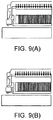
- FIG. 9(A) shows a master image the same as the master image of FIG. 8(A)
- FIG. 9(B) shows another image obtained by changing values of the imaging parameters and imaging the work-piece 50 by the appearance inspection device 1 of the example.
- the image of FIG. 9(B) corresponds to an image in which "the distance from the center of the visual field to the work-piece" is shorter (improved) compared with the image of FIG. 8(B) .
- the type n' of the imaging parameters is 5, and the imaging parameters of 5 types include "the focal position", "the color average of image", “the variation of the color average of image", "the distance from the center of visual field to the work-piece", and "the distortion in the visual field".
- the individual evaluation value A1' related to "the focal position” is equal to 90
- the individual evaluation value A2' related to "the color average of image” is equal to 64
- the individual evaluation value A3' related to "the variation of the color average of image” is equal to 15
- the individual evaluation value A4' related to "the distance from the center of visual field to the work-piece” is equal to 6
- the individual evaluation value A5' related to "the distortion in the visual field” is equal to 0.9
- Each of the set An'max is the same as the An'max used in the inspection of the work-piece 50 shown in FIG. 8(B) .
- the individual evaluation value related to "the distance from the center of the visual field to the work-piece" becomes small (good)
- the general evaluation value which is calculated by the calculation formula of the general evaluation value Max ⁇ (1-An'/An'max) ⁇ 100 ⁇ when the type n of the imaging parameters is 1-5, is 67.
- the parameter determining part 80 compares the set of values of the imaging parameters given to the image of FIG. 8(B) and the set of values of the imaging parameters given to the image of FIG. 9(B) , and determines the set of values of the imaging parameters given to the image of FIG. 9(B) in which the general evaluation value is smaller as the set of optimum values.
- imaging parameters are not limited hereto and there is a shutter speed which may be 1/200 seconds, 1/1000 seconds, 1/8000 seconds and the like.
- the light emission intensity of illumination 255, 128, 64 and the like among the gradation of 0-255 are used.
- the light emission pattern of illumination in light emitting surfaces of four divisions, a lighting of all the four surfaces, a lighting of only the left and right surfaces, a lighting of only the upper and lower surfaces or the like are used.
- the general evaluation value is quantitatively defined.
- the imaging parameter can be precisely determined.
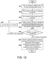
- FIG. 10 is an operation flow when fully searching plural types of imaging parameters that are set.
- the user sets the maximum value Anmax of the individual evaluation value (step S21).
- the user sets a search range of the imaging parameters (step S22).
- the user sets a search range of each axis of the robot (step S23).
- Step S21 to step S23 are preliminary settings before the search.
- the imaging processing part 70 and the parameter determining part 80 image the work-piece and calculate the individual evaluation value An (step S24).
- the parameter determining part 80 calculates the general evaluation values (step S25).
- the parameter determining part 80 judges whether the search is completed (step S26); when the search is not completed, the flow proceeds to step S27 and changes the search conditions, and then returns to step S24.
- the search is ended and the flow proceeds to step S28.
- the parameter determining part 80 sorts a plurality of general evaluation values calculated in step S25 (step S28).
- the parameter determining part 80 sets the values of the imaging parameters including a robot axis position when the general evaluation value is the best within the plurality of general evaluation values as the set of optimum values (step S29).
- the plural types of imaging parameters that are set are fully searched, but it is not limited hereto. It may be that a search for a subset (which is called a first imaging parameter) of one type or plural types of imaging parameters within the plural types of imaging parameters that are set is performed at first, and for the first imaging parameter, the value of the imaging parameter when the individual evaluation value is the best or the set of values of the imaging parameters when the general evaluation value is the best is obtained as a first optimum value or a first set of optimum values.
- a subset which is called a first imaging parameter
- this partial search may be sequentially repeated.
- FIG. 11A-FIG. 11C shows an operation flow when repeating the partial search in the plural types of imaging parameters that are set.
- the user sets the maximum value Anmax of the individual evaluation value (step S31).
- the user sets the search range of the imaging parameters (step S32).
- the user sets the search range of each axis of the robot (step S33).
- Step S31 to step S33 are preliminary settings before the search.
- the imaging processing part 70 and the parameter determining part 80 image the work-piece and calculate the individual evaluation value An which is the individual evaluation value An for "the focal position" that is used as the first imaging parameter in this example (step S34).
- the parameter determining part 80 calculates the general evaluation value (step S35).
- the parameter determining part 80 judges whether the search is completed (step S36); when the search is not completed, the flow proceeds to step S37 and changes the search condition, which is the "robot Z-axis" in the example, and then returns to step S34.
- the search is ended and the flow proceeds to step S38.
- the parameter determining part 80 sorts a plurality of general evaluation values calculated in step S35 (step S38).
- the parameter determining part 80 sets the values of the imaging parameters (in the example, "the focal position” and "the robot Z-axis position") when the general evaluation value is the best within the plurality of general evaluation values as the set of optimum values (step S39).
- the flow proceeds to step 40 of FIG. 11B .
- the imaging processing part 70 and the parameter determining part 80 image the work-piece, and calculate the individual evaluation value An which is the individual evaluation value An for "the work-piece position in the visual field” and "the distortion in the visual field” that are set as the second imaging parameter in this example (step S40).
- the parameter determining part 80 calculates the general evaluation value (step S41).
- the parameter determining part 80 judges whether the search is completed (step S42); when the search is not completed, the flow proceeds to step S43 and changes the search condition, which is the value of "axis positions except Z-axis of the robot" in the example, and then returns to step S40.
- the search is ended and proceeds to step S44.
- the parameter determining part 80 sorts the plurality of general evaluation values calculated in step S41 (step S44).
- the parameter determining part 80 sets the values of the imaging parameters (in this example, "the work-piece position in the visual field", “the distortion in the visual field” and “the robot axis position except Z-axis of the robot") when the general evaluation value is the best within the plurality of general evaluation values as the set of optimum values (step S45).
- the flow proceeds to step 46 of FIG. 11C .
- the imaging processing part 70 and the parameter determining part 80 image the object and calculate the individual evaluation value An which is the individual evaluation value An for "the intensity of illumination” and “the uniformity of illumination” that are set as the third imaging parameter in this example (step S46).
- the parameter determining part 80 calculate the general evaluation value (step S47).
- the parameter determining part 80 judges whether the search is completed (step S48); when the search is not completed, the flow proceeds to step 49 and changes the search conditions, which are "the intensity of illumination” and "the light emission pattern of illumination” in the example, and then returns to step S46.
- the search is ended and the flow proceeds to step S50.
- the parameter determining part 80 sorts the plurality of general evaluation values calculated in step S47 (step S50).
- the parameter determining part 80 sets the values of the imaging parameters (in this example, "the light emission intensity of illumination” and “the light emission pattern of illumination") when the general evaluation value is the best within the plurality of general evaluation values as the set of optimum values and completes the search (step S51).
- the parameter determining part 80 obtains, for the predetermined first imaging parameter, the value of the imaging parameter when the individual evaluation value is the best or the set of values of the imaging parameters when the general evaluation value is the best as the first optimum value or the first set of optimum values. Accordingly, for example, for the imaging parameter emphasized in advance by the user (the first imaging parameter), a combination number between the imaging parameters is limited, and the set of optimum values (the first set of optimum values) is rapidly obtained.
- the parameter determining part 80 obtains, for the second imaging parameter different from the first imaging parameter, the value of the imaging parameter when the individual evaluation value is the best or the set of values of the imaging parameters when the general evaluation value is the best as the second optimum value or the second set of optimum values.
- the combination number between the imaging parameters is limited, and the set of optimum values (the second set of optimum values) is rapidly obtained.
- This partial search may be further repeated. As a result, according to the appearance inspection device of the example, the optimum values of various imaging parameters are obtained rapidly.
- the search operation is not limited to the above operation.
- the partial search may be repeatedly performed while gradually narrowing down the search range.
- the control device 40 can be configured by a processor which operates according to a program, a non-volatile semiconductor memory and the like.
- the control device 40 can be substantially configured by a computer device (for example, programmable logic controller (PLC) and the like).
- PLC programmable logic controller
- the appearance inspection method described in FIG. 3 is configured as a program for the computer to execute.
- the program is recorded in a computer-readable non-transitory recording medium. In this case, by making the computer device read and execute these programs recorded in the recording medium, the above-described appearance inspection method can be implemented.
Landscapes
- Physics & Mathematics (AREA)
- General Physics & Mathematics (AREA)
- Biochemistry (AREA)
- Life Sciences & Earth Sciences (AREA)
- Chemical & Material Sciences (AREA)
- Analytical Chemistry (AREA)
- Health & Medical Sciences (AREA)
- General Health & Medical Sciences (AREA)
- Immunology (AREA)
- Pathology (AREA)
- Engineering & Computer Science (AREA)
- Computer Vision & Pattern Recognition (AREA)
- Investigating Materials By The Use Of Optical Means Adapted For Particular Applications (AREA)
- Length Measuring Devices By Optical Means (AREA)
- Image Analysis (AREA)
Abstract
Description
- The disclosure relates to an appearance inspection device, an appearance inspection method, and a program, more specifically to a device, a method, and a program for inspecting an appearance of an object.
- Conventionally, as for this type of appearance inspection device, for example the following appearance inspection device is known which moves a relative position of a product and an imaging device mounted on a robot arm and the like to image the product by the imaging device and inspects whether the product is unqualified based on the taken images, as disclosed in Japanese Laid-open No.
2014-126494 - [Patent literature 1] Japanese Laid-Open No
2014-126494 - Meanwhile, in an appearance inspection using an imaging device mounted on a robot arm and the like, values of various imaging parameters such as a relative position of a product and the imaging device, a focal position of the imaging device, and an illumination intensity of an illumination part are determined from an enormous combination of values of the imaging parameters by a user relying on experience and intuition. Accordingly, it takes time to determine an optimum value of the imaging parameter. Therefore, it is required that the optimum values of various imaging parameters are easily determined at a short time. However, there is a problem in the appearance inspection device described in patent literature 1 (Japanese Laid-Open No
2014-126494 - Therefore, a problem of the present invention is to provide an appearance inspection device, an appearance inspection method and a program that can easily determine the optimum values of various imaging parameters in an appearance inspection.
- In order to solve the above problem, the appearance inspection device of the disclosure is an inspection device for inspecting an appearance of an object and includes:
- an imaging part for taking an image of the object;
- an illumination part irradiating a light to the object;
- a moving means that changes relative positions of at least two or more portions within the object, the imaging part, and the illumination part;
- an imaging processing part that performs, in a state that the illumination part irradiates a light to the object, a processing for changing imaging parameters and taking a plurality of images by the imaging part under a condition that plural types of imaging parameters with mutually different properties are set variably, the plural types of imaging parameters including a change of the relative position between the object and the imaging part caused by the moving means; and
- a parameter determining part that determines a set of optimum values of the plural types of imaging parameters that are set variably based on the plurality of taken images.
- In the specification, the "object" refers to, for example, a three-dimensional article which is used as an inspection target, such as a product, a work-piece and so on.
- In addition, the "appearance" refers to, for example, a shape, a pattern, and color or the like of the object.
- In addition, the "plural types of imaging parameters with mutually different properties " refer to, for example, a work-piece position in the visual field, a focal position of the imaging device, a uniformity of illumination, an intensity of illumination, a distortion in the visual field, a shutter speed, and a light emission pattern and so on. In addition, the plural types of imaging parameters are not limited hereto.
- In addition, the "moving means" refers to, for example, a system which includes a one-axis device (which refers to a control axis), a two-axis device, or an industrial robot of three or more axes, and which is capable of causing the object and the imaging part to move and/or rotate relatively.
- In addition, the "relative position" refers to information expressed by a total of six parameters of three translation components and three rotation components, and the change thereof means that at least more than one of the six parameters changes.
- In the appearance inspection device of the disclosure, the moving means changes relative positions of at least two or more portions of the object, the imaging part, and the illumination part. The illumination part irradiates a light to the object. The imaging processing part performs, in the state that the illumination part irradiates a light to the object, the processing for changing imaging parameters and taking a plurality of images by the imaging part under a condition that plural types of imaging parameters with mutually different properties are set variably, the plural types of imaging parameters including a change of the relative position between the object and the imaging part caused by the moving means. Then, the parameter determining part determines the set of optimum values of the plural types of imaging parameters that are set variably based on the plurality of photographed images. Accordingly, in the appearance inspection device, the set of optimum values for the plural types of imaging parameters is determined based on the plurality of photographed images from an enormous combination of the imaging parameters. As a result, the optimum values of various imaging parameters can be easily determined.
- In the appearance inspection device of one embodiment, the parameter determining part respectively calculates an individual evaluation value representing the quality degree for each of the imaging parameters for the plurality of images, calculates a general evaluation value by a predetermined calculation formula based on the individual evaluation value, and obtains a set of values of the imaging parameters when the general evaluation value is the best within the plurality of images as the set of optimum values.
- In the appearance inspection device of this embodiment, various optimal imaging parameters can be easily determined based on the general evaluation value.
- In the appearance inspection device of one embodiment, the individual evaluation value is calculated based on a degree to which feature amounts extracted from the plurality of images are consistent with predetermined ideal values or a degree to which the plurality of images are consistent with a pre-registered master image.
- In the appearance inspection device of this embodiment, the individual evaluation value is quantitatively calculated. As a result, the imaging parameters can be precisely determined.
- In the appearance inspection device of one embodiment, for a predetermined first imaging parameter, the parameter determining part calculates, under a condition that other parameters except the first imaging parameter are fixed, a value of the imaging parameter when the individual evaluation value is the best or a set of values of the imaging parameters when the general evaluation value is the best as a first optimum value or a first set of optimum values; after that, for a second imaging parameter different from the first imaging parameter, the parameter determining part calculates, under a condition that other parameters except the second imaging parameter different from the first imaging parameter are fixed, the value of the imaging parameter when the individual evaluation value is the best or the set of values of the imaging parameters when the general evaluation value is the best as a second optimum value or a second set of optimum values.
- In addition, the "first imaging parameter" refers to a subset of one type or plural types of imaging parameters within the plural types of parameters. The "second imaging parameter" refers to a subset of one type or plural types of imaging parameters within a set of the rest parameters except the first imaging parameter within the plural types of parameters.
- In the appearance inspection device of this embodiment, the parameter determining part firstly obtains, for the predetermined first imaging parameter, the value of the imaging parameter when the individual evaluation value is the best or the set of values of the imaging parameters when the general evaluation value is the best as the first optimum value or the first set of optimum values. Accordingly, for example, for the imaging parameter (the first imaging parameter) emphasized in advance by a user, a combination number between the imaging parameters is limited, and the first optimum value or the first set of optimum values is rapidly obtained. After that, the parameter determining part obtains, for the second imaging parameter different from the first imaging parameter, the value of the imaging parameter when the individual evaluation value is the best or the set of values of the imaging parameters when the general evaluation value is the best as the second optimum value or the second set of optimum values. In this way, for the rest imaging parameter (the second imaging parameter), a combination number between the imaging parameters is limited, and the second optimum value or the second set of optimum value is rapidly obtained. Accordingly, according to the appearance inspection device of this embodiment, the optimum values of various imaging parameters can be rapidly obtained.
- In another aspect, the appearance inspection method of the disclosure is an appearance inspection method for inspecting an appearance of an object by the appearance inspection device and includes:
- a step for performing, in a state that the illumination part irradiates a light to the object, a processing for changing imaging parameters and taking a plurality of images by the imaging part under a condition that plural types of imaging parameters with mutually different properties are set variably, the plural types of imaging parameters including a change of the relative position between the object and the imaging part caused by the moving means; and
- a step for determining a set of optimum values of the plural types of imaging parameters that are set variably based on the plurality of photographed images.
- In the appearance inspection method of the disclosure, from an enormous combination of imaging parameters, the set of optimum values for the plural types of imaging parameters is determined based on the plurality of photographed images. As a result, the optimum values of various imaging parameters can be easily determined.
- In another aspect, a program of the disclosure
makes a computer execute the appearance inspection method. - As seen from the above, according to the appearance inspection device, the appearance inspection method and the program of the disclosure, the optimum values of various imaging parameters can be easily determined.
-
-
FIG. 1 is an obliquely observed schematic view of an appearance of an appearance inspection device of one embodiment of the disclosure. -
FIG. 2 is a drawing showing a block configuration of a control system of the appearance inspection device. -
FIG. 3 is an operation flow chart of an appearance inspection method of one embodiment using the appearance inspection device. -
FIG. 4 is a drawing showing a relation between an individual evaluation value An related to an imaging parameter and a maximum individual evaluation value Anmax for an image obtained by imaging a certain work-piece. -
FIG. 5 is a drawing showing a relation between the individual evaluation value An related to the imaging parameter and the maximum individual evaluation value Anmax for another image obtained by changing the value of the imaging parameter to image the work-piece. -
FIG. 6(A) is a drawing showing an example of a master image to be a model for a certain work-piece.FIG. 6(B) is a drawing showing an image obtained by changing the value of the imaging parameter to image the work-piece. -
FIG. 7(A) is a drawing showing the same master image as inFIG. 6(A) .FIG. 7(B) is a drawing showing another image obtained by further changing the value of the imaging parameter to image the work-piece. -
FIG. 8(A) is a drawing showing an example of a master image to be a model for a certain work-piece.FIG. 8(B) is a drawing showing an image obtained by changing the value of the imaging parameter to image the work-piece. -
FIG. 9(A) is a drawing showing the same master image as inFIG. 8(A) .FIG. 9(B) is a drawing showing another image obtained by further changing the value of the imaging parameter to image the work-piece. -
FIG. 10 is an operation flow chart when fully searching plural types of imaging parameters that are set. -
FIG. 11A is a drawing showing a preliminary part of an operation flow when repeating a partial search in the plural types of imaging parameters that are set. -
FIG. 11B is a drawing showing a middle part of the operation flow when repeating the partial search in the plural types of imaging parameters that are set. -
FIG. 11C is a drawing showing a latter part of the operation flow when repeating the partial search in the plural types of imaging parameters that are set. -
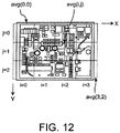
FIG. 12 is a drawing showing the meaning of a pixel average value avg (i,j) in a specified range related to an individual evaluation value of the uniformity of illumination. - In the following, embodiments of the disclosure are specifically described with reference to the drawings.
-
FIG. 1 is an obliquely observed schematic view of an appearance of an appearance inspection device (denoted by asymbol 1 as a whole) of one embodiment of the appearance inspection device of the disclosure. - As shown in
FIG. 1 , theappearance inspection device 1 includes arobot 10 which serves as a moving means, animaging part 20, anillumination part 30, and acontrol device 40 in general. In theappearance inspection device 1, thecontrol device 40 controls operations of therobot 10, theillumination part 30 and theimaging part 20. Thecontrol device 40 controls a posture of therobot 10, theillumination part 30 irradiates a light to an object (appropriately referred to as a "work-piece" hereinafter), and theimaging part 20 images the work-piece 50 so that an appearance inspection is performed. - The
robot 10 performs an assembly or movement or the like of the work-piece 50. In this example, therobot 10 is provided with theimaging part 20 on a leading end part of anarm 11 of therobot 10. Therobot 10 causes theimaging part 20 to move relatively to the work-piece 50. The relative movement can also include a rotation movement. In this example, therobot 10 is provided with theimaging part 20, but it is not limited hereto, theimaging part 20 may be fixed and installed in a location different from therobot 10. In this case, therobot 10 grips the work-piece 50 on the leading end part of thearm 11, and therobot 10 can cause the work-piece 50 to move relatively to the fixedimaging part 20. - The
robot 10 can freely move the position of the leading end part of thearm 11 in a predetermined movable range by interlocking and driving each axis according to a control command given from thecontrol device 40. Besides, in the example, an industrial six-axis articulated robot is used, but therobot 10 is not limited hereto as long as the work-piece 50 and theimaging part 20 can be relatively moved and/or rotated by therobot 10. The moving means may be, for example, a one-axis device, a two-axis device, and a three-axis device. - In this example, the
imaging part 20 consists of a camera and images in a state that theillumination part 30 irradiates a light to the work-piece 50. The taken image is output to thecontrol device 40. Theimaging part 20 can change a focal position and the like according to a control command including imaging parameters given from thecontrol device 40 and image the work-piece 50. - In this example, the
illumination part 30 consists of a lamp serving as a light source and irradiates a light to the work-piece 50. Theillumination part 30 can change an intensity, a light emission pattern and the like of theillumination part 30 according to the control command including imaging parameters given from thecontrol device 40. Theillumination part 30 is fixed to be movable with respect to the work-piece 50. - The
control device 40 is provided with astorage part 60, animaging processing part 70, and aparameter determining part 80, which are shown inFIG. 2 described later. Thecontrol device 40 operates to cause theimaging part 20 to take a plurality of images in a state that the illumination part irradiates a light to the work-piece 50. Thecontrol device 40 determines a set of optimum values of plural types of imaging parameters based on the plurality of taken images. - The work-
piece 50 is a three-dimensional article such as an assembly object which is used as an appearance inspection object. For example, the work-piece 50 may be a product and so on. The work-piece 50 may be placed on a fixed inspection table (not shown) or be placed and move on a conveyor (not shown). -
FIG. 2 shows a block configuration implemented by a program for performing the appearance inspection method in theappearance inspection device 1. Thecontrol device 40 of theappearance inspection device 1 is provided with thestorage part 60, theimaging processing part 70, and theparameter determining part 80. - The
storage part 60 consists of a non-volatile semiconductor memory in the example. In the example, thestorage part 60 can store not only the images taken by theimaging part 20 but also a master image described later. - The
imaging processing part 70 transmits the control command including imaging parameters to therobot 10 and controls the posture of therobot 10. Theimaging processing part 70 transmits the control command including imaging parameters to theillumination part 30 and adjusts the intensity of illumination and the uniformity of illumination and so on. Theimaging processing part 70 transmits the control command including imaging parameters to theimaging part 20 and adjusts the focal position or the like of theimaging part 20. Theimaging processing part 70 performs a processing of taking a plurality of images of the work-piece 50 by theimaging part 20 in a state that a light is irradiated to the work-piece 50. At that time, for each imaging, plural types of imaging parameters with mutually different properties which include a change of the relative position of theimaging part 20 and therobot 10 are variably set. Accordingly, theimaging processing part 70 can capture a plurality of taken images for the work-piece 50 in a state that the plural types of imaging parameters with mutually different properties are set. - The
parameter determining part 80 receives the plurality of taken images from theimaging processing part 70, and calculates an individual evaluation value for each of the plurality of taken images based on a degree to which feature amounts extracted from the images are consistent with predetermined ideal values or a degree to which the images are consistent with a pre-registered master image. Specifically, theparameter determining part 80 denotes a number corresponding to a type of the imaging parameter as n, an individual evaluation value representing a quality degree (the better, the larger) for each imaging parameter as An, and a maximum individual evaluation value as Anmax. Then, theparameter determining part 80 calculates a general evaluation value by a calculation formula Max{(1-An/Anmax)×100), and obtains a set of values of the imaging parameters for the image which gives the smallest general evaluation value for the work-piece 50 as a set of optimum values. Here, a sign Max{(1-An/Anmax)×100} means the maximum value within (1-An/Anmax)×100. A ratio An/Anmax normalizes and represents the degree to which the individual evaluation value An is good. Accordingly, (1-An/Anmax)×100 represents the degree to which the individual evaluation value An is poor in percentage. As a result, when the worst individual evaluation value An is smaller, the general evaluation value is smaller and better. - The above
imaging processing part 70 and theparameter determining part 80 are configured by a processor (for example, Central Processing Unit (CPU)) operating in accordance with the program. Thecontrol device 40 may include, in addition to the above-described elements, an auxiliary storage device such as a HDD (Hard Disk Drive), a network or a communication interface capable of communicating by wire or radio waves, an input device such as a keyboard or a touch panel, and an output device such as a display. Besides, thecontrol device 40 may be included in therobot 10. -
FIG. 3 shows an operation flow of the appearance inspection method of one embodiment performed by theappearance inspection device 1. This flow is started, for example, in the way that theappearance inspection device 1 receives a start instruction of operation from a user via the communication interface or the input device or the like of thecontrol device 40. - The
imaging processing part 70 changes the relative positions between at least two portions of the work-piece 50, theimaging part 20, and theillumination part 30 by the robot 10 (step S10). - The
imaging processing part 70 irradiates a light to the work-piece 50 by the illumination part 30 (step S11). - The
imaging processing part 70 performs, in the state that theillumination part 30 irradiates a light to the work-piece 50, a processing for changing imaging parameters and taking a plurality of images by theimaging part 20 under a condition that plural types of imaging parameters with mutually different properties are set variably (step S12). The plural types of imaging parameters with mutually different properties include a change of the relative position between the work-piece 50 and theimaging part 20 caused by therobot 10. - The
parameter determining part 80 determines a set of optimum values of the plural types of imaging parameters that are set variably based on the plurality of taken images (step S13). - In this example, from an enormous combination of imaging parameters, a set of optimum values for the plural types of imaging parameters is determined based on the plurality of taken images. As a result, the optimum values of various imaging parameters can be easily determined.
- As for the individual evaluation value An related to the imaging parameters, in the example, the type n of the imaging parameters is 5, and the individual evaluation value An includes a work-piece position in the visual field, a focal position, a uniformity of illumination, an intensity of illumination, and a distortion in the visual field. The individual evaluation value An is obtained as follows.
- (1) The individual evaluation value of the work-piece position in the visual field (that is, a distance from the center of the visual field to the work-piece) is obtained by the following formula.
When the work-piece position is (mx, my) and the center of the visual field is (cx, cy), the individual evaluation value is
- (2) The individual evaluation value of the focal position is obtained by the following formula.
When an average of the concentration values (in this example, the concentration values of monochrome images is shown) of a color C in the pixels on the image is

- (3) The individual evaluation value of the uniformity of illumination is obtained as follows.
As shown inFIG. 12 , theparameter determining part 80 divides in a rectangular range of a plurality of rows and a plurality of columns (in the example, three rows and four columns). Then, a number representing an X-direction (column direction) position is set as i (wherein, i=0, 1, 2, 3) and a number representing a Y-direction (row direction) position is set as j (wherein, j=0, 1, 2), and a pixel average value avg(i,j) of each range is obtained. At this time, the individual evaluation value of the uniformity of illumination is obtained by the following formula.
- (4) The individual evaluation value of the intensity of illumination is obtained by the following formula.
avg(Ci) - (5) As for the individual evaluation value of the distortion in the visual field,
when a homogeneous coordinate of a coordinate on a standard image is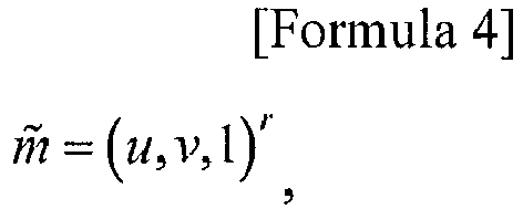


- Accordingly, the individual evaluation value of the distortion in the visual field is obtained by the following formula.

- Here, g represents a distortion in the X-direction, and h represents a distortion of the Y-direction. Besides, without being limited to this example, a rotation movement amount can be obtained using a, b, d, e. An amount of enlargement-contraction transformation can be obtained using a, b, d, e, g, h.
- Before an inspection using the
appearance inspection device 1, the maximum value Anmax of the individual evaluation value of the imaging parameters is set in advance. The setting is a value predetermined by the user or a maximum value of the individual evaluation value calculated based on the master image. In the example, the type n of the imaging parameters is 5; as shown inFIG. 4 , the imaging parameters of 5 types include "the work-piece position in the visual field", "the focal position", "the uniformity of illumination", "the intensity of illumination", and "the distortion in the visual field". In the example, the maximum value Anmax of the individual evaluation value of the imaging parameters is set as follows. - (1) As a maximum value A1max of the individual evaluation value of "the work-piece position in the visual field", the maximum value of the individual evaluation value calculated based on the master image is set.
- (2) As a maximum value A2max of the individual evaluation value of "the focal position", the maximum value of the focal position, for example 105, which is predetermined by the user is set. Or the maximum value of the individual evaluation value calculated based on the master image is set.
- (3) As a maximum value A3max of the individual evaluation value of "the uniformity of illumination", the maximum value of the individual evaluation value calculated based on the master image is set.
- (4) As a maximum value A4max of the individual evaluation value of "the intensity of illumination", an intermediate value, for example 128, within the gradation of 0-255 which is predetermined by the user is set. Or the maximum value of the individual evaluation value calculated based on the master image is set.
- (5) As a maximum value A5max of the individual evaluation value of "the distortion in the visual field", the maximum value of the individual evaluation value calculated based on the master image is set.
-
FIG. 4 shows a relation between the individual evaluation value An related to the imaging parameter and the maximum value Anmax of the individual evaluation value for an image obtained by imaging a certain work-piece 50. - Lengths from the center O to the vertex of an external regular pentagon among a double pentagon in
FIG. 4 respectively represent the maximum values (A1max-A5max) of the individual evaluation values. Lengths from the center O to the vertex of an internal regular pentagon among the double pentagon in the drawing respectively represent the individual evaluation values (A1-A5) related to the imaging parameters. -
FIG. 5 shows a double pentagon similar toFIG. 4 for other images obtained by changing the values of the imaging parameters and imaging the work-piece 50. Lengths from the center O to the vertex of an external regular pentagon among a double pentagon inFIG. 5 respectively represent the maximum values (Almax-A5max) of the individual evaluation values. Lengths from the center O to the vertex of an internal pentagon among the double pentagon in the drawing respectively represent the individual evaluation values (A1-A5). - In the case of
FIG. 5 , the ratio A1/A1max related to the work-piece position in the visual field is smaller compared withFIG. 4 . That is, when the general evaluation value is calculated by the calculation formula Max{(1-An/Anmax)×100}, as a result, the general evaluation value is larger (worse). Accordingly, it is shown that the set of values of the imaging parameters ofFIG. 5 is unsuitable as a set of values of the imaging parameters compared with the set of values of the imaging parameters ofFIG. 4 . In this example, the imaging parameters ofFIG. 4 in which the general evaluation value is small is determined as the set of optimum values. -
FIG. 6(A) shows a master image registered in thestorage 60 in thecontrol device 40 in advance (an image to be a model for a certain work-piece 50), andFIG. 6(B) shows an image obtained by imaging the work-piece 50 by theappearance inspection device 1 of the example. The image ofFIG. 6(B) corresponds to an image out of focus compared with the image ofFIG. 6(A) . In the example, the type n' of the imaging parameters is 5, and the imaging parameters of 5 types include "a focal position", "a color average of image", "a variation of the color average of image", "a distance from the center of visual field to the work-piece", and "a distortion in the visual field". - In the example, the individual evaluation value A1' related to "the focal position" is equal to 58, the individual evaluation value A2' related to "the color average of image" is equal to 100, the individual evaluation value A3' related to "the variation of the color average of image" is equal to 11, the individual evaluation value A4' related to "the distance from the center of visual field to the work-piece" is equal to 6, and the individual evaluation value A5' related to "the distortion in the visual field" is equal to 0.8.
- In the example, the maximum value An'max of the individual evaluation value of the imaging parameters is set as follows. A1'max related to "the focal position" is equal to 105, A2'max related to "the color average of image" is equal to 128, A3'max related to "the variation of the color average of image" is equal to 10, A4'max related to "the distance from the center of visual field to the work-piece" is equal to 5, and A5'max related to "the distortion in the visual field" is equal to 1.0.
- As a result, the individual evaluation value related to "the focal position" is the largest (worst), and thus the general evaluation value calculated by a calculation formula of the general evaluation value Max{(1-An'/An'max)×100} is 45.
-
FIG. 7(A) shows a master image the same as the master image ofFIG. 6(A) , andFIG. 7(B) shows another image obtained by changing values of the imaging parameters and imaging the work-piece 50 by theappearance inspection device 1 of the example. The image ofFIG. 7(B) corresponds to an image in focus (which is improved) compared with the image ofFIG. 6(B) . In the example, similar to the above example, the type n' of the imaging parameters is 5, and the imaging parameters of 5 types include "the focal position", "the color average of image", "the variation of the color average of image", "the distance from the center of visual field to the work-piece", and "the distortion in the visual field". - In the example, the individual evaluation value A1' related to "the focal position" is equal to 90, the individual evaluation value A2' related to "the color average of image" is equal to 120, the individual evaluation value A3' related to "the variation of the color average of image" is equal to 11, the individual evaluation value A4' related to "the distance from the center of visual field to the work-piece" is equal to 6, and the individual evaluation value A5' related to "the distortion in the visual field" is equal to 0.9.
- Each of the set Anmax is the same as the Anmax used in the inspection of the work-
piece 50 shown inFIG. 6(B) . - As a result, the individual evaluation value related to "the focal position" becomes small (good), and the general evaluation value calculated by the calculation formula of the general evaluation value Max{(1-An'/An'max)×100) is 20.
- According to the above results, the
parameter determining part 80 compares the set of values of the imaging parameters given to the image ofFIG. 6(B) and the set of values of the imaging parameters given to the image ofFIG. 7(B) , and determines the set of values of the imaging parameters giving the image ofFIG. 7(B) in which the general evaluation value is smaller as the set of optimum values. -
FIG. 8(A) shows a master image registered in thestorage 60 in thecontrol device 40 in advance (an image to be a model for a certain work-piece 50);FIG. 8(B) shows an image obtained by imaging the work-piece 50 by theappearance inspection device 1 of this example. The image ofFIG. 8(B) corresponds to an image in which "the distance from the center of the visual field to the work-piece" is longer (worse) compared with the image ofFIG. 8(A) . In the example, the type n' of the imaging parameters is 5, and the imaging parameters of 5 types include "the focal position", "the color average of image", "the variation of the color average of image", "the distance from the center of visual field to the work-piece", and "the distortion in the visual field". - In the example, the individual evaluation value A1' related to "the focal position" is equal to 92, the individual evaluation value A2' related to "the color average of image" is equal to 188, the individual evaluation value A3' related to "the variation of the color average of image" is equal to 15, the individual evaluation value A4' related to "the distance from the center of visual field to the work-piece" is equal to 15, and the individual evaluation value A5' related to "the distortion in the visual field" is equal to 0.9.
- In the example, the maximum value An'max of the individual evaluation value of the imaging parameters is set as follows. A1'max related to "the focal position" is equal to 102, A2'max related to "the color average of image" is equal to 192, A3'max related to "the variation of the color average of image" is equal to 10, A4'max related to "the distance from the center of visual field to the work-piece" is equal to 5, and A5'max related to "the distortion in the visual field" is equal to 1.0.
- As a result, the individual evaluation value related to "the distance from the center of the visual field to the work-piece" is the largest (worst), and thus the general evaluation value, which is calculated by a calculation formula of the general evaluation value Max{(1-An'/An'max)×100} when the type n of the imaging parameters is 1-5, is 140.
-
FIG. 9(A) shows a master image the same as the master image ofFIG. 8(A) , andFIG. 9(B) shows another image obtained by changing values of the imaging parameters and imaging the work-piece 50 by theappearance inspection device 1 of the example. The image ofFIG. 9(B) corresponds to an image in which "the distance from the center of the visual field to the work-piece" is shorter (improved) compared with the image ofFIG. 8(B) . In the example, similar to the above example, the type n' of the imaging parameters is 5, and the imaging parameters of 5 types include "the focal position", "the color average of image", "the variation of the color average of image", "the distance from the center of visual field to the work-piece", and "the distortion in the visual field". - In the example, the individual evaluation value A1' related to "the focal position" is equal to 90, the individual evaluation value A2' related to "the color average of image" is equal to 64, the individual evaluation value A3' related to "the variation of the color average of image" is equal to 15, the individual evaluation value A4' related to "the distance from the center of visual field to the work-piece" is equal to 6, and the individual evaluation value A5' related to "the distortion in the visual field" is equal to 0.9
- Each of the set An'max is the same as the An'max used in the inspection of the work-
piece 50 shown inFIG. 8(B) . - As a result, the individual evaluation value related to "the distance from the center of the visual field to the work-piece" becomes small (good), and the general evaluation value, which is calculated by the calculation formula of the general evaluation value Max{(1-An'/An'max)×100} when the type n of the imaging parameters is 1-5, is 67.
- According to the above results, the
parameter determining part 80 compares the set of values of the imaging parameters given to the image ofFIG. 8(B) and the set of values of the imaging parameters given to the image ofFIG. 9(B) , and determines the set of values of the imaging parameters given to the image ofFIG. 9(B) in which the general evaluation value is smaller as the set of optimum values. - Besides, other examples of the imaging parameters are not limited hereto and there is a shutter speed which may be 1/200 seconds, 1/1000 seconds, 1/8000 seconds and the like. In addition, as for the light emission intensity of illumination, 255, 128, 64 and the like among the gradation of 0-255 are used. In addition, as for the light emission pattern of illumination, in light emitting surfaces of four divisions, a lighting of all the four surfaces, a lighting of only the left and right surfaces, a lighting of only the upper and lower surfaces or the like are used.
- In the example, the general evaluation value is quantitatively defined. As a result, the imaging parameter can be precisely determined.
-
FIG. 10 is an operation flow when fully searching plural types of imaging parameters that are set. - The user sets the maximum value Anmax of the individual evaluation value (step S21). The user sets a search range of the imaging parameters (step S22). The user sets a search range of each axis of the robot (step S23). Step S21 to step S23 are preliminary settings before the search.
- Next, the
imaging processing part 70 and theparameter determining part 80 image the work-piece and calculate the individual evaluation value An (step S24). Theparameter determining part 80 calculates the general evaluation values (step S25). Theparameter determining part 80 judges whether the search is completed (step S26); when the search is not completed, the flow proceeds to step S27 and changes the search conditions, and then returns to step S24. When the search is completed, the search is ended and the flow proceeds to step S28. - Next, the
parameter determining part 80 sorts a plurality of general evaluation values calculated in step S25 (step S28). Next, theparameter determining part 80 sets the values of the imaging parameters including a robot axis position when the general evaluation value is the best within the plurality of general evaluation values as the set of optimum values (step S29). - In the above search example, the plural types of imaging parameters that are set are fully searched, but it is not limited hereto. It may be that a search for a subset (which is called a first imaging parameter) of one type or plural types of imaging parameters within the plural types of imaging parameters that are set is performed at first, and for the first imaging parameter, the value of the imaging parameter when the individual evaluation value is the best or the set of values of the imaging parameters when the general evaluation value is the best is obtained as a first optimum value or a first set of optimum values. After that, for a second imaging parameter different from the first imaging parameter (a set of the rest parameters except the first imaging parameter within the plural types of parameters), a value of the imaging parameter when the individual evaluation value is the best or a set of values of the imaging parameters when the general evaluation value is the best is obtained as a second optimum value or a second set of optimum values. Furthermore, in regard to a third imaging parameter different from the first imaging parameter and the second imaging parameter and a fourth imaging parameter (omitted below) different from the above imaging parameters, this partial search may be sequentially repeated.
-
FIG. 11A-FIG. 11C shows an operation flow when repeating the partial search in the plural types of imaging parameters that are set. - As shown in
FIG. 11A , the user sets the maximum value Anmax of the individual evaluation value (step S31). The user sets the search range of the imaging parameters (step S32). The user sets the search range of each axis of the robot (step S33). Step S31 to step S33 are preliminary settings before the search. - Next, the
imaging processing part 70 and theparameter determining part 80 image the work-piece and calculate the individual evaluation value An which is the individual evaluation value An for "the focal position" that is used as the first imaging parameter in this example (step S34). Theparameter determining part 80 calculates the general evaluation value (step S35). Theparameter determining part 80 judges whether the search is completed (step S36); when the search is not completed, the flow proceeds to step S37 and changes the search condition, which is the "robot Z-axis" in the example, and then returns to step S34. When the search is completed, the search is ended and the flow proceeds to step S38. - Next, the
parameter determining part 80 sorts a plurality of general evaluation values calculated in step S35 (step S38). Next, theparameter determining part 80 sets the values of the imaging parameters (in the example, "the focal position" and "the robot Z-axis position") when the general evaluation value is the best within the plurality of general evaluation values as the set of optimum values (step S39). Next, the flow proceeds to step 40 ofFIG. 11B . - As shown in
FIG. 11B , theimaging processing part 70 and theparameter determining part 80 image the work-piece, and calculate the individual evaluation value An which is the individual evaluation value An for "the work-piece position in the visual field" and "the distortion in the visual field" that are set as the second imaging parameter in this example (step S40). Theparameter determining part 80 calculates the general evaluation value (step S41). Theparameter determining part 80 judges whether the search is completed (step S42); when the search is not completed, the flow proceeds to step S43 and changes the search condition, which is the value of "axis positions except Z-axis of the robot" in the example, and then returns to step S40. When the search is completed, the search is ended and proceeds to step S44. - Next, the
parameter determining part 80 sorts the plurality of general evaluation values calculated in step S41 (step S44). Next, theparameter determining part 80 sets the values of the imaging parameters (in this example, "the work-piece position in the visual field", "the distortion in the visual field" and "the robot axis position except Z-axis of the robot") when the general evaluation value is the best within the plurality of general evaluation values as the set of optimum values (step S45). Next, the flow proceeds to step 46 ofFIG. 11C . - As shown in
FIG. 11C , theimaging processing part 70 and theparameter determining part 80 image the object and calculate the individual evaluation value An which is the individual evaluation value An for "the intensity of illumination" and "the uniformity of illumination" that are set as the third imaging parameter in this example (step S46). Theparameter determining part 80 calculate the general evaluation value (step S47). Theparameter determining part 80 judges whether the search is completed (step S48); when the search is not completed, the flow proceeds to step 49 and changes the search conditions, which are "the intensity of illumination" and "the light emission pattern of illumination" in the example, and then returns to step S46. When the search is completed, the search is ended and the flow proceeds to step S50. - Next, the
parameter determining part 80 sorts the plurality of general evaluation values calculated in step S47 (step S50). Next, theparameter determining part 80 sets the values of the imaging parameters (in this example, "the light emission intensity of illumination" and "the light emission pattern of illumination") when the general evaluation value is the best within the plurality of general evaluation values as the set of optimum values and completes the search (step S51). - In the search operation of the example, firstly, the
parameter determining part 80 obtains, for the predetermined first imaging parameter, the value of the imaging parameter when the individual evaluation value is the best or the set of values of the imaging parameters when the general evaluation value is the best as the first optimum value or the first set of optimum values. Accordingly, for example, for the imaging parameter emphasized in advance by the user (the first imaging parameter), a combination number between the imaging parameters is limited, and the set of optimum values (the first set of optimum values) is rapidly obtained. After that, theparameter determining part 80 obtains, for the second imaging parameter different from the first imaging parameter, the value of the imaging parameter when the individual evaluation value is the best or the set of values of the imaging parameters when the general evaluation value is the best as the second optimum value or the second set of optimum values. In this way, for the rest imaging parameter (the first imaging parameter), the combination number between the imaging parameters is limited, and the set of optimum values (the second set of optimum values) is rapidly obtained. This partial search may be further repeated. As a result, according to the appearance inspection device of the example, the optimum values of various imaging parameters are obtained rapidly. - In addition, the search operation is not limited to the above operation. For example, the partial search may be repeatedly performed while gradually narrowing down the search range.
- The
control device 40 can be configured by a processor which operates according to a program, a non-volatile semiconductor memory and the like. In other words, thecontrol device 40 can be substantially configured by a computer device (for example, programmable logic controller (PLC) and the like). Accordingly, in an embodiment, the appearance inspection method described inFIG. 3 is configured as a program for the computer to execute. In addition, in an embodiment, the program is recorded in a computer-readable non-transitory recording medium. In this case, by making the computer device read and execute these programs recorded in the recording medium, the above-described appearance inspection method can be implemented. -
- 1
- appearance inspection device
- 10
- robot
- 20
- imaging part
- 30
- illumination part
- 40
- control device
- 50
- work-piece
- 70
- imaging processing part
- 80
- parameter determining part
Claims (6)
- An appearance inspection device (1), which is an inspection device for inspecting an appearance of an object, characterized in that comprising:an imaging part (20) for taking an image of the object;an illumination part (30) irradiating a light to the object;a moving means that changes relative positions of at least two or more portions within the object, the imaging part (20), and the illumination part (30);an imaging processing part (70) that performs, in a state that the illumination part (30) irradiates a light to the object, a processing for changing imaging parameters and taking a plurality of images by the imaging part (20) under a condition that plural types of imaging parameters with mutually different properties are set variably, the plural types of imaging parameters including a change of the relative position between the object and the imaging part (20) caused by the moving means; anda parameter determining part (80) that determines a set of optimum values of the plural types of imaging parameters that are set variably based on the plurality of taken images.
- The appearance inspection device (1) according to claim 1, wherein
the parameter determining part (80) respectively calculates an individual evaluation value representing the quality degree for each of the imaging parameters for the plurality of images, calculates a general evaluation value by a predetermined calculation formula based on the individual evaluation value, and obtains a set of values of the imaging parameters when the general evaluation value is the best within the plurality of images as the set of optimum values. - The appearance inspection device (1) according to claim 2, wherein
the individual evaluation value is calculated based on a degree to which feature amounts extracted from the plurality of images are consistent with predetermined ideal values, or a degree to which the plurality of images are consistent with a pre-registered master image. - The appearance inspection device (1) according to any one of claims 1 to 3, wherein
for a predetermined first imaging parameter, the parameter determining part (80) calculates, under a condition that other parameters except the first imaging parameter are fixed, a value of the imaging parameter when the individual evaluation value is the best or a set of values of the imaging parameters when the general evaluation value is the best as a first optimum value or a first set of optimum values; after that, for a second imaging parameter different from the first imaging parameter, the parameter determining part (80) calculates, under the condition that other parameters except the second imaging parameter are fixed, the value of the imaging parameter when the individual evaluation value is the best or the set of values of the imaging parameters when the general evaluation value is the best as a second optimum value or a second set of optimum values. - An appearance inspection method for inspecting an appearance of an object by the appearance inspection device (1) according to claim 1, comprising:a step for performing, in a state that the illumination part (30) irradiates a light to the object, a processing for changing imaging parameters and taking a plurality of images by the imaging part (20) under a condition that plural types of imaging parameters with mutually different properties are set variably, the plural types of imaging parameters including a change of the relative position between the object and the imaging part (20) caused by the moving means; anda step for determining a set of optimum values of the plural types of imaging parameters that are set variably based on the plurality of taken images.
- A program for making a computer execute the appearance inspection method according to claim 5.
Applications Claiming Priority (1)
| Application Number | Priority Date | Filing Date | Title |
|---|---|---|---|
| JP2018045668A JP6977634B2 (en) | 2018-03-13 | 2018-03-13 | Visual inspection equipment, visual inspection methods and programs |
Publications (1)
| Publication Number | Publication Date |
|---|---|
| EP3540413A1 true EP3540413A1 (en) | 2019-09-18 |
Family
ID=65030949
Family Applications (1)
| Application Number | Title | Priority Date | Filing Date |
|---|---|---|---|
| EP19151771.3A Withdrawn EP3540413A1 (en) | 2018-03-13 | 2019-01-15 | Appearance inspection device, appearance inspection method and program |
Country Status (4)
| Country | Link |
|---|---|
| US (1) | US10794691B2 (en) |
| EP (1) | EP3540413A1 (en) |
| JP (1) | JP6977634B2 (en) |
| CN (1) | CN110274538A (en) |
Families Citing this family (5)
| Publication number | Priority date | Publication date | Assignee | Title |
|---|---|---|---|---|
| JP7159615B2 (en) * | 2018-05-22 | 2022-10-25 | セイコーエプソン株式会社 | Image processing device and robot system |
| JP6860098B1 (en) * | 2020-02-10 | 2021-04-14 | オムロン株式会社 | Image inspection device, image inspection program, lighting setting device |
| US11816754B2 (en) | 2020-03-13 | 2023-11-14 | Omron Corporation | Measurement parameter optimization method and device, and computer control program stored on computer-readable storage medium |
| JPWO2022085185A1 (en) * | 2020-10-23 | 2022-04-28 | ||
| WO2023090152A1 (en) * | 2021-11-17 | 2023-05-25 | 三菱電機株式会社 | Image processing device and image processing method |
Citations (6)
| Publication number | Priority date | Publication date | Assignee | Title |
|---|---|---|---|---|
| EP0569589A1 (en) * | 1991-07-12 | 1993-11-18 | Omron Corporation | Apparatus and method for determining or setting adequate illuminating and photographing condition, etc., in picture processing system; and apparatus and method for aiding the determination or setting |
| JP2005003476A (en) * | 2003-06-11 | 2005-01-06 | Nikon Corp | Surface inspection device |
| US20110103679A1 (en) * | 2009-10-29 | 2011-05-05 | Mitutoyo Corporation | Autofocus video tool and method for precise dimensional inspection |
| US20110298901A1 (en) * | 2008-12-24 | 2011-12-08 | Snecma | Method for the non-destructive inspection of a mechanical part |
| US20130162807A1 (en) * | 2011-12-23 | 2013-06-27 | Mitutoyo Corporation | Points from focus operations using multiple light settings in a machine vision system |
| JP2014126494A (en) | 2012-12-27 | 2014-07-07 | Seiko Epson Corp | Inspection support device, inspection support method, robot system, control device, robot and program |
Family Cites Families (12)
| Publication number | Priority date | Publication date | Assignee | Title |
|---|---|---|---|---|
| US4853771A (en) * | 1986-07-09 | 1989-08-01 | The United States Of America As Represented By The Secretary Of The Navy | Robotic vision system |
| JP3235387B2 (en) * | 1991-07-12 | 2001-12-04 | オムロン株式会社 | Lighting condition setting support apparatus and method |
| JP2003270163A (en) * | 2002-03-15 | 2003-09-25 | Dainippon Printing Co Ltd | Inspection method and apparatus |
| GB0424417D0 (en) * | 2004-11-03 | 2004-12-08 | Univ Heriot Watt | 3D surface and reflectance function recovery using scanned illumination |
| JP2006324920A (en) * | 2005-05-18 | 2006-11-30 | Hitachi Maxell Ltd | Electronic camera and control method thereof |
| JP5303420B2 (en) * | 2009-10-01 | 2013-10-02 | 株式会社キーエンス | Imaging condition setting device and imaging condition setting method for optical information reader |
| JP2013222740A (en) * | 2012-04-13 | 2013-10-28 | Panasonic Corp | Visual inspection device and visual inspection method |
| JP2014142213A (en) * | 2013-01-22 | 2014-08-07 | Canon Inc | Photographing parameter determination device and control method of the same |
| JP6473919B2 (en) * | 2013-06-24 | 2019-02-27 | パナソニックIpマネジメント株式会社 | Master-slave robot control device and control method, robot, master-slave robot control program, and integrated electronic circuit for master-slave robot control |
| WO2015156125A1 (en) * | 2014-04-11 | 2015-10-15 | 株式会社 日立メディコ | Medical imaging device and medical imaging method |
| JP5778311B1 (en) * | 2014-05-08 | 2015-09-16 | 東芝機械株式会社 | Picking apparatus and picking method |
| JP2017138106A (en) * | 2016-02-01 | 2017-08-10 | 日立金属株式会社 | Surface defect determination method |
-
2018
- 2018-03-13 JP JP2018045668A patent/JP6977634B2/en active Active
-
2019
- 2019-01-10 CN CN201910022869.9A patent/CN110274538A/en active Pending
- 2019-01-15 EP EP19151771.3A patent/EP3540413A1/en not_active Withdrawn
- 2019-01-16 US US16/248,808 patent/US10794691B2/en active Active
Patent Citations (6)
| Publication number | Priority date | Publication date | Assignee | Title |
|---|---|---|---|---|
| EP0569589A1 (en) * | 1991-07-12 | 1993-11-18 | Omron Corporation | Apparatus and method for determining or setting adequate illuminating and photographing condition, etc., in picture processing system; and apparatus and method for aiding the determination or setting |
| JP2005003476A (en) * | 2003-06-11 | 2005-01-06 | Nikon Corp | Surface inspection device |
| US20110298901A1 (en) * | 2008-12-24 | 2011-12-08 | Snecma | Method for the non-destructive inspection of a mechanical part |
| US20110103679A1 (en) * | 2009-10-29 | 2011-05-05 | Mitutoyo Corporation | Autofocus video tool and method for precise dimensional inspection |
| US20130162807A1 (en) * | 2011-12-23 | 2013-06-27 | Mitutoyo Corporation | Points from focus operations using multiple light settings in a machine vision system |
| JP2014126494A (en) | 2012-12-27 | 2014-07-07 | Seiko Epson Corp | Inspection support device, inspection support method, robot system, control device, robot and program |
Also Published As
| Publication number | Publication date |
|---|---|
| US10794691B2 (en) | 2020-10-06 |
| US20190285406A1 (en) | 2019-09-19 |
| JP6977634B2 (en) | 2021-12-08 |
| JP2019158602A (en) | 2019-09-19 |
| CN110274538A (en) | 2019-09-24 |
Similar Documents
| Publication | Publication Date | Title |
|---|---|---|
| EP3540413A1 (en) | Appearance inspection device, appearance inspection method and program | |
| CN116542914B (en) | Weld seam extraction and fitting method based on 3D point cloud | |
| CN114170227B (en) | Product surface defect detection method, device, equipment and storage medium | |
| JP6740288B2 (en) | Object inspection apparatus, object inspection system, and method for adjusting inspection position | |
| CN109483573A (en) | Machine learning device, robot system and machine learning method | |
| JP4935109B2 (en) | Substrate inspection device, inspection logic setting method and inspection logic setting device | |
| CN115713476B (en) | A visual inspection method, apparatus, and readable storage medium based on laser welding. | |
| CN112139683B (en) | Evaluation device, evaluation method, evaluation system, and recording medium | |
| CN106707674A (en) | Automatic focusing method of projection equipment and the projection equipment | |
| CN103988069A (en) | Inspection area setting method for image inspecting device | |
| US12315132B2 (en) | Appearance inspection apparatus and appearance inspection method | |
| US8538165B2 (en) | Image measuring apparatus, program, and teaching method of image measuring apparatus | |
| JP2023002201A (en) | Sample observation device and method | |
| WO2019194064A1 (en) | Image processing device, image processing method, appearance inspection system, and appearance inspection method | |
| WO2019194065A1 (en) | Image processing device, image processing method, appearance inspection system, and appearance inspection method | |
| CN103727877A (en) | Fruit identifying and locating method, device and system | |
| DE102019133753A1 (en) | TOOLS FOR AUGMENTED REALITY IN LIGHT DESIGN | |
| CN115816447B (en) | Visual servo control method and device for mechanical arm and electronic equipment | |
| CN117934942A (en) | Weld joint recognition model, training method and weld joint tracking method | |
| CN115456975B (en) | A Real-Time Segmentation Method for Display Defects in Multiple Backgrounds Based on Improved Mask R-CNN | |
| CN117608069A (en) | An automatic focusing method, system, device and storage medium | |
| JP2014022662A (en) | Wafer appearance inspection device and sensitivity threshold setting method in wafer appearance inspection device | |
| CN111009024A (en) | Method for generating dynamic image, electronic equipment and storage medium | |
| JP7045103B1 (en) | Data Expansion Devices, Data Expansion Systems, and Data Expansion Programs | |
| CN116210026A (en) | Imaging condition adjustment device and imaging condition adjustment method |
Legal Events
| Date | Code | Title | Description |
|---|---|---|---|
| PUAI | Public reference made under article 153(3) epc to a published international application that has entered the european phase |
Free format text: ORIGINAL CODE: 0009012 |
|
| STAA | Information on the status of an ep patent application or granted ep patent |
Free format text: STATUS: REQUEST FOR EXAMINATION WAS MADE |
|
| 17P | Request for examination filed |
Effective date: 20190115 |
|
| AK | Designated contracting states |
Kind code of ref document: A1 Designated state(s): AL AT BE BG CH CY CZ DE DK EE ES FI FR GB GR HR HU IE IS IT LI LT LU LV MC MK MT NL NO PL PT RO RS SE SI SK SM TR |
|
| AX | Request for extension of the european patent |
Extension state: BA ME |
|
| RBV | Designated contracting states (corrected) |
Designated state(s): AL AT BE BG CH CY CZ DE DK EE ES FI FR GB GR HR HU IE IS IT LI LT LU LV MC MK MT NL NO PL PT RO RS SE SI SK SM TR |
|
| STAA | Information on the status of an ep patent application or granted ep patent |
Free format text: STATUS: EXAMINATION IS IN PROGRESS |
|
| 17Q | First examination report despatched |
Effective date: 20210820 |
|
| STAA | Information on the status of an ep patent application or granted ep patent |
Free format text: STATUS: THE APPLICATION IS DEEMED TO BE WITHDRAWN |
|
| 18D | Application deemed to be withdrawn |
Effective date: 20250715 |