EP3540373A1 - System and method for receiving signal information for networking using a free space optical link - Google Patents
System and method for receiving signal information for networking using a free space optical link Download PDFInfo
- Publication number
- EP3540373A1 EP3540373A1 EP19154912.0A EP19154912A EP3540373A1 EP 3540373 A1 EP3540373 A1 EP 3540373A1 EP 19154912 A EP19154912 A EP 19154912A EP 3540373 A1 EP3540373 A1 EP 3540373A1
- Authority
- EP
- European Patent Office
- Prior art keywords
- light beam
- micro
- collimated light
- channel plate
- plate collimator
- Prior art date
- Legal status (The legal status is an assumption and is not a legal conclusion. Google has not performed a legal analysis and makes no representation as to the accuracy of the status listed.)
- Granted
Links
Images




Classifications
-
- H—ELECTRICITY
- H04—ELECTRIC COMMUNICATION TECHNIQUE
- H04B—TRANSMISSION
- H04B10/00—Transmission systems employing electromagnetic waves other than radio-waves, e.g. infrared, visible or ultraviolet light, or employing corpuscular radiation, e.g. quantum communication
- H04B10/11—Arrangements specific to free-space transmission, i.e. transmission through air or vacuum
- H04B10/112—Line-of-sight transmission over an extended range
- H04B10/1121—One-way transmission
-
- G—PHYSICS
- G02—OPTICS
- G02B—OPTICAL ELEMENTS, SYSTEMS OR APPARATUS
- G02B13/00—Optical objectives specially designed for the purposes specified below
- G02B13/16—Optical objectives specially designed for the purposes specified below for use in conjunction with image converters or intensifiers, or for use with projectors, e.g. objectives for projection TV
-
- H—ELECTRICITY
- H04—ELECTRIC COMMUNICATION TECHNIQUE
- H04B—TRANSMISSION
- H04B10/00—Transmission systems employing electromagnetic waves other than radio-waves, e.g. infrared, visible or ultraviolet light, or employing corpuscular radiation, e.g. quantum communication
- H04B10/60—Receivers
- H04B10/66—Non-coherent receivers, e.g. using direct detection
- H04B10/67—Optical arrangements in the receiver
-
- G—PHYSICS
- G02—OPTICS
- G02B—OPTICAL ELEMENTS, SYSTEMS OR APPARATUS
- G02B13/00—Optical objectives specially designed for the purposes specified below
- G02B13/001—Miniaturised objectives for electronic devices, e.g. portable telephones, webcams, PDAs, small digital cameras
- G02B13/0015—Miniaturised objectives for electronic devices, e.g. portable telephones, webcams, PDAs, small digital cameras characterised by the lens design
- G02B13/005—Miniaturised objectives for electronic devices, e.g. portable telephones, webcams, PDAs, small digital cameras characterised by the lens design having spherical lenses only
-
- G—PHYSICS
- G02—OPTICS
- G02B—OPTICAL ELEMENTS, SYSTEMS OR APPARATUS
- G02B26/00—Optical devices or arrangements for the control of light using movable or deformable optical elements
- G02B26/08—Optical devices or arrangements for the control of light using movable or deformable optical elements for controlling the direction of light
-
- G—PHYSICS
- G02—OPTICS
- G02B—OPTICAL ELEMENTS, SYSTEMS OR APPARATUS
- G02B27/00—Optical systems or apparatus not provided for by any of the groups G02B1/00 - G02B26/00, G02B30/00
- G02B27/30—Collimators
-
- G—PHYSICS
- G02—OPTICS
- G02B—OPTICAL ELEMENTS, SYSTEMS OR APPARATUS
- G02B7/00—Mountings, adjusting means, or light-tight connections, for optical elements
- G02B7/02—Mountings, adjusting means, or light-tight connections, for optical elements for lenses
- G02B7/021—Mountings, adjusting means, or light-tight connections, for optical elements for lenses for more than one lens
-
- H—ELECTRICITY
- H04—ELECTRIC COMMUNICATION TECHNIQUE
- H04B—TRANSMISSION
- H04B10/00—Transmission systems employing electromagnetic waves other than radio-waves, e.g. infrared, visible or ultraviolet light, or employing corpuscular radiation, e.g. quantum communication
- H04B10/11—Arrangements specific to free-space transmission, i.e. transmission through air or vacuum
-
- G—PHYSICS
- G02—OPTICS
- G02B—OPTICAL ELEMENTS, SYSTEMS OR APPARATUS
- G02B2207/00—Coding scheme for general features or characteristics of optical elements and systems of subclass G02B, but not including elements and systems which would be classified in G02B6/00 and subgroups
- G02B2207/123—Optical louvre elements, e.g. for directional light blocking
Definitions
- This disclosure is generally related to free space optical linking and, in particular, to a system and method for receiving signal information for networking using a free space optical link.
- Typical free space optical link methods enable wide field of view operations by employing mechanical gimbals to slew a narrow field of view optical aperture over a wide angle.
- Initial laser communication signal discovery, acquisition, and tracking depend upon the mechanical gimbal pointing the narrow field of view optical aperture correctly for signal acceptance.
- Discovery of a new participant desiring to enter the network typically requires an additional non-directional laser beacon source and receiver aperture able to capture light from beacon sources over a wide angle field of view.
- the receiver aperture may determine the location of the new participant using a wide field of view optical receiver. After the location of the source relative to the receiver is established, a separate narrow-field aperture may be pointed toward the source to achieve an adequate signal-to-noise ratio for processing and demodulation of the optical signal.
- Wide field of view optical receivers are typically subject to significant noise associated with an incoming collimated laser light signal. While able to determine an incident angle of the laser light signal, wide field of view optical receivers are typically unable to demodulate and retrieve any data being carried by the laser light signal.
- a separate, narrow field optical receiver may be used to demodulate the signal. Multiple receivers add to the cost and decrease the efficiency of free space optical link systems. Further, using mechanical gimbals to direct the narrow field optical receiver to a newly acquired network participant may introduce additional mechanical systems, which add to the complexity of systems.
- a system for optical detection includes a focal plane array.
- the system further includes one or more lenses configured to focus a collimated light beam received at the one or more lenses onto the focal plane array, where a position of the collimated light beam on the focal plane array is based on an incident angle of propagation of the collimated light beam at the one or more lenses.
- the system also includes a micro-channel plate collimator positioned within an optical path of the collimated light beam.
- the system includes a processor configured to determine the incident angle of propagation of the collimated light beam and to retrieve data encoded within the collimated light beam.
- the micro-channel plate collimator is in an electrically passive state.
- the micro-channel plate collimator includes an opaque substrate having a first surface and a second surface, and a plurality of transparent channels within the opaque substrate.
- the plurality of transparent channels within the opaque substrate are arranged in a square lattice pattern.
- the plurality of transparent channels within the opaque substrate are arranged in a triangle lattice pattern.
- the plurality of transparent channels within the opaque substrate are arranged in a square lattice pattern along a first portion of the micro-channel plate collimator, and the plurality of transparent channels within the opaque substrate are arranged in a triangle lattice pattern along a second portion of the micro-channel plate collimator.
- a spatial density of the transparent channels within the opaque substrate along a first portion of the micro-channel plate collimator is less than along a second portion of the micro-channel plate collimator.
- the first surface is convexly curved and the second surface is concavely curved.
- a detection surface of the focal plane array is convexly curved.
- the system includes a dewar, where the focal plane array is positioned within the dewar, and a cold stop.
- the micro-channel plate collimator is positioned within the dewar.
- the micro-channel plate collimate is positioned outside of the dewar.
- at least one of the one or more lenses extends through an exterior boundary of the dewar.
- a method for optical detection includes receiving a collimated light beam at one or more lenses.
- the method further includes focusing the collimated light beam onto a focal plane array, where a position of the collimated light beam on the focal plane array is based on an incident angle of propagation of the collimated light beam at the one or more lenses.
- the method also includes passing the collimated light beam through a micro-channel plate collimator positioned within an optical path of the collimated light beam.
- the method includes determining the incident angle of propagation of the collimated light beam based on the position of the collimated light beam on the focal plane array.
- the method further includes retrieving data encoded within the collimated light beam.
- the method includes receiving the collimated light beam into a dewar before the collimated light beam is passed through the micro-channel plate collimator. In some embodiments, the method includes receiving the collimated light beam into a dewar after the collimated light beam is passed through the micro-channel plate collimator.
- a micro-channel plate collimator apparatus includes an opaque substrate having a first surface and a second surface.
- the apparatus further includes a plurality of transparent channels within the opaque substrate, where a spatial density of the transparent channels within the opaque substrate is greater along a first portion of the micro-channel plate collimator than along a second portion of the micro-channel plate collimator.
- the plurality of transparent channels are arranged in a square lattice pattern along the first portion of the micro-channel plate collimator, and the plurality of transparent channels are arranged in a triangle pattern along the second portion of the micro-channel plate collimator.
- the plurality of transparent channels have a first cross-section radius along the first portion of the micro-channel plate and a second cross-section radius along the second portion, where the first cross-section radius is smaller than the second cross-section radius.
- the plurality of transparent channels have a first depth along the first portion of the micro-channel plate and a second depth along the second portion, where the first depth is smaller than the second depth.
- FIG. 1 a block diagram of an embodiment of a system 100 for receiving signal information using a free space optical link is depicted.
- the system may include one or more lenses 102, a micro-channel plate collimator 104, a focal plane array 106, and a processor 108.
- the system may be implemented in a vehicle, such as aircraft, for vehicle-to-vehicle communication. Other applications are also possible.
- the one or more lenses 102 may direct a collimated light beam 110, such as a communication grade laser, onto the focal plane array 106 along an optical path 112.
- the lenses 102 may be configured in a wide-field of view (WFOV) configuration.
- the lenses 102 may direct the light beam 110 such that a position 114 of the collimated light beam 110 on the focal plane array 106 is based on an incident angle of propagation, in azimuth and elevation, of the collimated light beam 110 as it reaches the lenses 102.
- the lenses 102 include a complex multi-lens optical system as described with reference to the embodiments herein.
- the micro-channel plate collimator 104 may be configured as a filter to reduce the collimated light beam 110. As such, the micro-channel plate collimator 104 may be in an electrically passive state. As used herein, electrically passive means that no external voltage is applied across the micro-channel plate collimator 104, enabling it to filter noise from the collimated light beam 110 rather than perform amplification processes.
- the processor 108 may be communicatively coupled to the focal plane array 106. As such the processor 108 may be able to determine the position 114 of the collimated light beam 110 on the focal plane array 106. Based on the position 114, the processor may be configured to calculate the incident angle of propagation of the collimated light beam 110, thereby pinpointing a source of the collimated light beam 110. In addition, the collimated light beam 110, having been filtered by the micro-channel plate collimator, may be demodulated by the processor 108 to retrieve data encoded therein. In that way, a communication link may be set up with the source of the collimated light beam 110.
- the processor 108 may include a central processing unit (CPU), a graphical processing unit (GPU), a digital signal processor (DSP), a peripheral interface controller (PIC), or another type of microprocessor. It may be implemented as an integrated circuit, a field programmable gate array (FPGA), an application specific integrated circuit (ASIC), a combination of logic gate circuitry, other types of digital or analog electrical design components, or the like, or combinations thereof. In some embodiments, the processor 108 may be distributed across multiple processing elements, relying on distributive processing operations.
- CPU central processing unit
- GPU graphical processing unit
- DSP digital signal processor
- PIC peripheral interface controller
- FPGA field programmable gate array
- ASIC application specific integrated circuit
- the processor 108 may be distributed across multiple processing elements, relying on distributive processing operations.
- the processor may include memory such as random access memory (RAM), read only memory (ROM), magnetic disk memory, optical disk memory, flash memory, another type of memory capable of storing data and processor instructions, or the like, or combinations thereof.
- the memory, or portions thereof may be located externally or remotely from the rest of the processor 108.
- the memory of the processor 108 may store instructions that, when executed by the processor 108, cause the processor 108 to perform operations.
- the operations may correspond to any operations described herein for receiving signal information using a free space optical link.
- the collimated light beam 110 may be received at the lenses 102.
- the lenses 102 may direct the collimated light beam 110 onto the focal plane array 106.
- the light beam 110 may follow the optical path 112, entering the lenses at an angle of incident and eventually reaching the focal plane array 106 at the position 114.
- the position 114 where the collimated light beam 110 strikes the focal plane array 106 may enable the processor 108 to determining a position of the source of the collimated light beam 110.
- the micro-channel plate collimator 104 may be positioned within the optical path 112 of the light beam 110 in order to reduce processed background noise entering portions of the one or more lenses 102 and thus increase the processed signal-to-noise ratio. Although depicted as being between the lenses 102 and the focal plane array 106, the micro-channel plate collimator 104 may be positioned anywhere along the path 112 as described in the embodiments herein.
- a benefit of the system 100 is that a single wide angle optical system may both determine the position of the source of the collimated light beam 110 and demodulate the collimated light beam 110 to retrieve data therefrom, as compared to other systems that may require an additional narrow field of view optical system to demodulate the signal.
- the complexity and weight of the system 100 may be reduced as compared to typical free space optical receiver systems.
- Other advantages may exist.
- the micro-channel plate collimator 104 may include an opaque substrate 202 having a first surface 204 and a second surface 206.
- the micro-channel plate collimator 104 may include a plurality of transparent channels 208.
- the micro-channel plate collimator 104 may include a first portion 220 in which the transparent channels 208 are arranged in a first pattern, a second portion 222 in which the transparent channels 208 are arranged in a second pattern, and a third portion 224 in which the transparent channels 208 are arranged in a third pattern.
- the transparent channels 208 may be arranged in a square lattice. Each of the transparent channels 208 may have a diameter D1 and may be separated by a spacing D2. The transparent channels 208 may be concentrated within an area determined by a distance D3. Each of the parameters, D1, D2, and D3, may affect both the intensity and the level of noise associated with a collimated light beam passing through the micro-channel plate collimator 104.
- the transparent channels 208 may be arranged in a triangular lattice. Because the transparent channels 208 within the first portion 220 and the third portion 224 are arranged in a square lattice, and the transparent channels 208 within the second portion 222 are arranged in a triangular lattice, a spatial density of the transparent channels 208 within the first portion 220 and the third portion 224 of the micro-channel plate collimator 104 is less than within the second portion 222 of the micro-channel plate collimator. The different spatial density may substantially increase the intensity of a beam of light passing through the second portion 222 relative to the first portion 220 and the third portion 224.
- the second portion 222 may be referred to as a pupil.
- the term pupil refers to a portion of the micro-channel plate collimator, such as the second portion 222, that permits significantly more light through than other portions, such as the first portion 220 and the third portion 224.
- the transparent channels 208 may have a first cross-section radius along the first portion 220 and the third portion 224 of the micro-channel plate collimator 104 and a second cross-section radius along the second portion 222.
- D1 may be smaller in the first portion 220 and third portion 224 than in the second portion 222. This may enable more light to penetrate the micro-channel plate collimator 104 in the second portion 222.
- a larger diameter D1 parameter may also permit more interference to pass through, thereby decreasing a signal-to-noise ratio of a collimated light beam.
- Each of the parameters D1, D2, and D3 may be optimized based on a particular application to enable sufficient light intensity to pass through the micro-channel plate collimator 104 for detection and for demodulation.
- FIG. 2 depicts the micro-channel plate collimator 104 as having a rectangular shape, in practice it may have other shapes, such as a circular shape.
- the second portion 222 may be a circular center to of the micro-channel collimator 104 and the first portion 220 and the second portion 224 may correspond to annular areas surrounding the second portion 222.
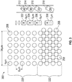
- a sample pattern 300 of the plurality of transparent channels 208 is depicted.
- the diameter D1 may correspond to 4 ⁇ m
- the spacing D2 may correspond to 6 ⁇ m
- the distance D3 may correspond to 34 ⁇ m.
- these parameters are for illustrative purposes only. Other measurements may be used and fall within the scope of this disclosure. The measurements may be determined based on parameters, such as wavelength, phase, and intensity, of associated with a collimated light beam (e.g., a laser) used.
- the diameter D1 is selected to be large enough to avoid interfering with the collimated light beam at a wavelength level.
- the transparent channels 208 may have a square lattice pattern along a first portion 220 of the pattern 300 and a triangle lattice pattern along a second portion 222 of the pattern 300. This enables more light to pass through the second portion 222 than the first portion 220. Although not depicted in FIG. 3 , permitting more light to pass through the second portion 222 may also be achieved by decreasing the spacing D2 between each transparent channel 208 within the second portion 222 to less than 6 ⁇ m or by increasing the diameter D1 of the transparent channels 208 within the second portion to greater than 4 ⁇ m. These are design parameters that may be modified based on particular applications.
- Additional design parameters include a depth of each of the transparent channels 208.
- the depth may vary continuously at different points within the pattern 300.
- a first depth 302 may be relatively small.
- the first depth 302 is depicted as 4 ⁇ m.
- the depths of each of the transparent channels 208 may gradually increase.
- a second depth 304 may correspond to 5 ⁇ m
- a third depth 306 may correspond to 6 ⁇ m
- a fourth depth 308 may correspond to 7 ⁇ m.
- Each of the depths 302-308 may limit light passing through the transparent channels 208 based on an incident angle of the light.
- the first depth 302 may limit light having an incident angle of propagation that exceeds a first angle 312, which corresponds to 44° in the example of FIG. 3 .
- the second depth 304 may limit light having an incident angle of propagation that exceeds a second angle 314 of 38°.
- the third depth 306 may limit light having an incident angle of propagation that exceeds a third angle 316 of 33°.
- the fourth depth 308 may limit light having an incident angle of propagation that exceeds a fourth angle 318 of 28°.
- the intensity of light passing through may also be decreased, which increases the difficulty of demodulating a received signal to retrieve data encoded therein.
- An advantage of the pattern 300 is that more surface area is provided for light to enter the transparent channels 208 within the second portion 222 to allow for a greater intensity of light in areas where the transparent channels 208 have greater depths, thereby permitting demodulation of a received beam of light, while also enabling a determination of the incident angle of propagation of the light. Other advantages may exist.
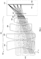
- the system 100 includes the one or more lenses 102, the micro-channel plate collimator 104, and the focal plane array 106. Although not depicted in FIG. 4 , the system 100 also includes the processor 108.
- the lenses 102 are depicted in a configuration usable to enable wide field of view operation.
- the lenses 102 may include a first lens 402, a second lens 403, a third lens 404, a fourth lens 405, a fifth lens 406, and a sixth lens 407.
- the lenses 402-407 may be any combination of biconvex lenses, plano-convex lenses, positive meniscus lenses, negative meniscus lenses, plano-concave lenses, and biconcave lenses, as may be beneficial for particular applications.
- the precise lenses used and their configurations are not intended to be limited to those depicted in the figures.
- the system 100 may include a dewar 410.
- a dewar may be a vacuum-insulated container having a first container encompassed within a second container. Air may be evacuated from a space between the first and second containers in order to thermally isolate the contents of the first container.
- Other embodiments of a dewar may be also be used as would be understood by persons of ordinary skill in the art having the benefit of this disclosure.
- a cold stop 412 which may include a cryogenically cold aperture, may permit a directed collimated beam to pass to the focal plane array while emitting virtually no interfering energy.
- the dewar 410 and the cold stop 412 may enable the focal plane array 106 to detect light at low temperatures, with little or no interference, which may be beneficial for accurately determining the incident angle of propagation of a received beam of light and/or for demodulating a signal encoded therein.
- Some of the lenses 102 e.g., the lens 407) may be positioned within the dewar 410.
- the micro-channel plate collimator 104 may be positioned adjacent to the focal plane array 106 within the dewar 410.
- multiple beams of collimated light 420 may be received at the one or more lenses 102.
- the multiple beams of collimated light 420 may each have an incident angle of propagation upon reaching the lenses 102.
- the lenses 102 may direct the multiple beams of collimated light 420 through the cold stop 412 into the dewar 410 and onto the focal plane array 106.
- a position of the multiple light beams 420 may depend on the incident angle of propagation of each individual light beam when arriving at the lenses 102. Based on the position on the focal plane array 106, the incident angle of propagation may be determined, enabling the position of a source of each of the multiple light beams 420 to likewise be determined.
- the micro-channel plate collimator 104 may be positioned within a path of the multiple light beams 420, causing them to pass through the micro-channel plate collimator 104 before striking the focal plane array 106. As described herein, the micro-channel plate collimator 104 may filter noise from the multiple light beams while simultaneously permitting sufficient light intensity to pass therethrough for demodulating the multiple light beams to extract data therefrom.
- the micro-channel plate collimator 104 may include a first portion 220, a second portion 222, and a third portion 224.
- the second portion 222 may correspond to a pupil between the first portion 220 and third portion 224. As such, more light may be permitted to pass through the second portion 222 than the first portion 220 and the third portion 224.
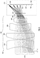
- the system 100 includes the one or more lenses 102, the micro-channel plate collimator 104, and the focal plane array 106. Although not depicted in FIG. 4 , the system 100 also includes the processor 108.
- the one or more lenses 102 of the embodiment of FIG. 6 may include a first lens 502, a second lens 503, a third lens 504, a fourth lens 505, and a fifth lens 506.
- the one or more lenses 102 may be simplified compared to FIG. 5 . Further, at least one of the lenses 102 (e.g., lens 506) may extend through an exterior boundary of the dewar 410.
- both the micro-channel plate collimator 104 and the focal plane array 106 may be curved.
- a first surface of the micro-channel plate collimator 104 e.g., the first surface 204 of FIG. 2
- a second surface e.g., the second surface 206 of FIG. 2
- the focal plane array 106 may be similarly convexly curved in order to enable the one or more lenses 102 to have a reduced complexity.
- the micro-channel plate collimator 104 is positioned outside the dewar 410 in a path of the multiple light beams 420 before the light beams 420 enter the first lens 502.
- other positions are possible.
- the micro-channel plate collimator 104 may include a first portion 220, a second portion 222, and a third portion 224.
- the second portion 222 may correspond to a pupil between the first portion 220 and third portion 224. As such, more light may be permitted to pass through the second portion 222 than the first portion 220 and the third portion 224.
- the method 800 may include receiving a collimated light beam at one or more lenses, at 802.
- the collimated light beam 110 may be received at the one or more lenses 102.
- the method 800 may further include focusing the collimated light beam onto a focal plane array, where a position of the collimated light beam on the focal plane array is based on an incident angle of propagation of the collimated light beam at the one or more lenses, at 804.
- the collimated light beam 110 may be focused onto the focal plane array 106.
- the method 800 may also include passing the collimated light beam through a micro-channel plate collimator positioned within an optical path of the collimated light beam, at 806.
- the collimated light beam 110 may pass through the micro-channel plate collimator 104.
- the method 800 may include determining the incident angle of propagation of the collimated light beam based on the position of the collimated light beam on the focal plane array, at 808.
- the processor 108 may determine the incident angle of propagation of the collimated light beam 110 based on the position 114 of the collimated light beam 110 on the focal plane array 106.
- the method 800 may further include retrieving data encoded within the collimated light beam, at 810.
- the processor 108 may retrieve data encoded within the collimated light beam 110.
- a benefit of the method 800 is that a single set of lenses and focal plane array can be used to both determine the position of a source of the collimated light beam and retrieve data encoded within the collimated light beam as opposed to systems that require another narrow field optical system to retrieve the data. Other advantages may exist.
Landscapes
- Physics & Mathematics (AREA)
- General Physics & Mathematics (AREA)
- Optics & Photonics (AREA)
- Electromagnetism (AREA)
- Engineering & Computer Science (AREA)
- Computer Networks & Wireless Communication (AREA)
- Signal Processing (AREA)
- Optical Communication System (AREA)
- Optical Couplings Of Light Guides (AREA)
- Lenses (AREA)
- Investigating Or Analysing Materials By Optical Means (AREA)
Abstract
Description
- This disclosure is generally related to free space optical linking and, in particular, to a system and method for receiving signal information for networking using a free space optical link.
- Typical free space optical link methods enable wide field of view operations by employing mechanical gimbals to slew a narrow field of view optical aperture over a wide angle. Initial laser communication signal discovery, acquisition, and tracking depend upon the mechanical gimbal pointing the narrow field of view optical aperture correctly for signal acceptance. Discovery of a new participant desiring to enter the network typically requires an additional non-directional laser beacon source and receiver aperture able to capture light from beacon sources over a wide angle field of view. The receiver aperture may determine the location of the new participant using a wide field of view optical receiver. After the location of the source relative to the receiver is established, a separate narrow-field aperture may be pointed toward the source to achieve an adequate signal-to-noise ratio for processing and demodulation of the optical signal.
- Wide field of view optical receivers are typically subject to significant noise associated with an incoming collimated laser light signal. While able to determine an incident angle of the laser light signal, wide field of view optical receivers are typically unable to demodulate and retrieve any data being carried by the laser light signal. A separate, narrow field optical receiver may be used to demodulate the signal. Multiple receivers add to the cost and decrease the efficiency of free space optical link systems. Further, using mechanical gimbals to direct the narrow field optical receiver to a newly acquired network participant may introduce additional mechanical systems, which add to the complexity of systems.
- Disclosed is a system that enables a wide field of view optical receiver to both determine an incident angle of an incoming signal and demodulate the signal to retrieve data transmitted therein. In an embodiment, a system for optical detection includes a focal plane array. The system further includes one or more lenses configured to focus a collimated light beam received at the one or more lenses onto the focal plane array, where a position of the collimated light beam on the focal plane array is based on an incident angle of propagation of the collimated light beam at the one or more lenses. The system also includes a micro-channel plate collimator positioned within an optical path of the collimated light beam. The system includes a processor configured to determine the incident angle of propagation of the collimated light beam and to retrieve data encoded within the collimated light beam.
- In some embodiments, the micro-channel plate collimator is in an electrically passive state. In some embodiments, the micro-channel plate collimator includes an opaque substrate having a first surface and a second surface, and a plurality of transparent channels within the opaque substrate. In some embodiments, the plurality of transparent channels within the opaque substrate are arranged in a square lattice pattern. In some embodiments, the plurality of transparent channels within the opaque substrate are arranged in a triangle lattice pattern. In some embodiments, the plurality of transparent channels within the opaque substrate are arranged in a square lattice pattern along a first portion of the micro-channel plate collimator, and the plurality of transparent channels within the opaque substrate are arranged in a triangle lattice pattern along a second portion of the micro-channel plate collimator. In some embodiments, a spatial density of the transparent channels within the opaque substrate along a first portion of the micro-channel plate collimator is less than along a second portion of the micro-channel plate collimator.
- In some embodiments, the first surface is convexly curved and the second surface is concavely curved. In some embodiments, a detection surface of the focal plane array is convexly curved. In some embodiments, the system includes a dewar, where the focal plane array is positioned within the dewar, and a cold stop. In some embodiments, the micro-channel plate collimator is positioned within the dewar. In some embodiments, the micro-channel plate collimate is positioned outside of the dewar. In some embodiments, at least one of the one or more lenses extends through an exterior boundary of the dewar.
- In an embodiment, a method for optical detection includes receiving a collimated light beam at one or more lenses. The method further includes focusing the collimated light beam onto a focal plane array, where a position of the collimated light beam on the focal plane array is based on an incident angle of propagation of the collimated light beam at the one or more lenses. The method also includes passing the collimated light beam through a micro-channel plate collimator positioned within an optical path of the collimated light beam. The method includes determining the incident angle of propagation of the collimated light beam based on the position of the collimated light beam on the focal plane array. The method further includes retrieving data encoded within the collimated light beam.
- In some embodiments, the method includes receiving the collimated light beam into a dewar before the collimated light beam is passed through the micro-channel plate collimator. In some embodiments, the method includes receiving the collimated light beam into a dewar after the collimated light beam is passed through the micro-channel plate collimator.
- In an embodiment, a micro-channel plate collimator apparatus includes an opaque substrate having a first surface and a second surface. The apparatus further includes a plurality of transparent channels within the opaque substrate, where a spatial density of the transparent channels within the opaque substrate is greater along a first portion of the micro-channel plate collimator than along a second portion of the micro-channel plate collimator.
- In some embodiments, the plurality of transparent channels are arranged in a square lattice pattern along the first portion of the micro-channel plate collimator, and the plurality of transparent channels are arranged in a triangle pattern along the second portion of the micro-channel plate collimator. In some embodiments, the plurality of transparent channels have a first cross-section radius along the first portion of the micro-channel plate and a second cross-section radius along the second portion, where the first cross-section radius is smaller than the second cross-section radius. In some embodiments, the plurality of transparent channels have a first depth along the first portion of the micro-channel plate and a second depth along the second portion, where the first depth is smaller than the second depth.
-
-
FIG. 1 depicts an embodiment of a system for receiving signal information using a free space optical link. -
FIG. 2 depicts an embodiment of a micro-channel plate collimator usable with a system for receiving signal information using a free space optical link. -
FIG. 3 depicts an embodiment of a channel pattern usable with a micro-channel plate collimator for a system for receiving signal information using a free space optical link. -
FIG. 4 depicts an embodiment of a system for receiving signal information using a free space optical link. -
FIG. 5 depicts an embodiment of a system for receiving signal information using a free space optical link. -
FIG. 6 depicts an embodiment of a system for receiving signal information using a free space optical link. -
FIG. 7 depicts an embodiment of a system for receiving signal information using a free space optical link. -
FIG. 8 depicts an embodiment of a method for receiving signal information using a free space optical link. - While the disclosure is susceptible to various modifications and alternative forms, specific embodiments have been shown by way of example in the drawings and will be described in detail herein. However, it should be understood that the disclosure is not intended to be limited to the particular forms disclosed. Rather, the intention is to cover all modifications, equivalents and alternatives falling within the scope of the disclosure.
- Referring to
FIG. 1 , a block diagram of an embodiment of asystem 100 for receiving signal information using a free space optical link is depicted. The system may include one ormore lenses 102, amicro-channel plate collimator 104, afocal plane array 106, and aprocessor 108. The system may be implemented in a vehicle, such as aircraft, for vehicle-to-vehicle communication. Other applications are also possible. - The one or
more lenses 102 may direct a collimatedlight beam 110, such as a communication grade laser, onto thefocal plane array 106 along anoptical path 112. In order to enable communication at wide angles, thelenses 102 may be configured in a wide-field of view (WFOV) configuration. Further, thelenses 102 may direct thelight beam 110 such that aposition 114 of the collimatedlight beam 110 on thefocal plane array 106 is based on an incident angle of propagation, in azimuth and elevation, of the collimatedlight beam 110 as it reaches thelenses 102. In an embodiment, thelenses 102 include a complex multi-lens optical system as described with reference to the embodiments herein. - The
micro-channel plate collimator 104 may be configured as a filter to reduce the collimatedlight beam 110. As such, themicro-channel plate collimator 104 may be in an electrically passive state. As used herein, electrically passive means that no external voltage is applied across themicro-channel plate collimator 104, enabling it to filter noise from the collimatedlight beam 110 rather than perform amplification processes. - The
processor 108 may be communicatively coupled to thefocal plane array 106. As such theprocessor 108 may be able to determine theposition 114 of the collimatedlight beam 110 on thefocal plane array 106. Based on theposition 114, the processor may be configured to calculate the incident angle of propagation of the collimatedlight beam 110, thereby pinpointing a source of the collimatedlight beam 110. In addition, the collimatedlight beam 110, having been filtered by the micro-channel plate collimator, may be demodulated by theprocessor 108 to retrieve data encoded therein. In that way, a communication link may be set up with the source of the collimatedlight beam 110. - The
processor 108 may include a central processing unit (CPU), a graphical processing unit (GPU), a digital signal processor (DSP), a peripheral interface controller (PIC), or another type of microprocessor. It may be implemented as an integrated circuit, a field programmable gate array (FPGA), an application specific integrated circuit (ASIC), a combination of logic gate circuitry, other types of digital or analog electrical design components, or the like, or combinations thereof. In some embodiments, theprocessor 108 may be distributed across multiple processing elements, relying on distributive processing operations. - Further, the processor may include memory such as random access memory (RAM), read only memory (ROM), magnetic disk memory, optical disk memory, flash memory, another type of memory capable of storing data and processor instructions, or the like, or combinations thereof. In some embodiments, the memory, or portions thereof, may be located externally or remotely from the rest of the
processor 108. The memory of theprocessor 108 may store instructions that, when executed by theprocessor 108, cause theprocessor 108 to perform operations. The operations may correspond to any operations described herein for receiving signal information using a free space optical link. - During operation, the collimated
light beam 110 may be received at thelenses 102. Thelenses 102 may direct the collimatedlight beam 110 onto thefocal plane array 106. Thelight beam 110 may follow theoptical path 112, entering the lenses at an angle of incident and eventually reaching thefocal plane array 106 at theposition 114. Theposition 114 where the collimatedlight beam 110 strikes thefocal plane array 106 may enable theprocessor 108 to determining a position of the source of the collimatedlight beam 110. Themicro-channel plate collimator 104 may be positioned within theoptical path 112 of thelight beam 110 in order to reduce processed background noise entering portions of the one ormore lenses 102 and thus increase the processed signal-to-noise ratio. Although depicted as being between thelenses 102 and thefocal plane array 106, themicro-channel plate collimator 104 may be positioned anywhere along thepath 112 as described in the embodiments herein. - A benefit of the
system 100 is that a single wide angle optical system may both determine the position of the source of the collimatedlight beam 110 and demodulate the collimatedlight beam 110 to retrieve data therefrom, as compared to other systems that may require an additional narrow field of view optical system to demodulate the signal. Thus, the complexity and weight of thesystem 100 may be reduced as compared to typical free space optical receiver systems. Other advantages may exist. - Referring to
FIG. 2 , an embodiment of amicro-channel plate collimator 104 usable with a system for receiving signal information using a free space optical link is depicted. Themicro-channel plate collimator 104 may include anopaque substrate 202 having afirst surface 204 and asecond surface 206. Themicro-channel plate collimator 104 may include a plurality oftransparent channels 208. - The
micro-channel plate collimator 104 may include afirst portion 220 in which thetransparent channels 208 are arranged in a first pattern, asecond portion 222 in which thetransparent channels 208 are arranged in a second pattern, and athird portion 224 in which thetransparent channels 208 are arranged in a third pattern. - In the
first portion 220 and thethird portion 224, thetransparent channels 208 may be arranged in a square lattice. Each of thetransparent channels 208 may have a diameter D1 and may be separated by a spacing D2. Thetransparent channels 208 may be concentrated within an area determined by a distance D3. Each of the parameters, D1, D2, and D3, may affect both the intensity and the level of noise associated with a collimated light beam passing through themicro-channel plate collimator 104. - In the
second portion 222, thetransparent channels 208 may be arranged in a triangular lattice. Because thetransparent channels 208 within thefirst portion 220 and thethird portion 224 are arranged in a square lattice, and thetransparent channels 208 within thesecond portion 222 are arranged in a triangular lattice, a spatial density of thetransparent channels 208 within thefirst portion 220 and thethird portion 224 of themicro-channel plate collimator 104 is less than within thesecond portion 222 of the micro-channel plate collimator. The different spatial density may substantially increase the intensity of a beam of light passing through thesecond portion 222 relative to thefirst portion 220 and thethird portion 224. Hence, thesecond portion 222 may be referred to as a pupil. As used herein, the term pupil refers to a portion of the micro-channel plate collimator, such as thesecond portion 222, that permits significantly more light through than other portions, such as thefirst portion 220 and thethird portion 224. - In some embodiments, the
transparent channels 208 may have a first cross-section radius along thefirst portion 220 and thethird portion 224 of themicro-channel plate collimator 104 and a second cross-section radius along thesecond portion 222. For example, D1 may be smaller in thefirst portion 220 andthird portion 224 than in thesecond portion 222. This may enable more light to penetrate themicro-channel plate collimator 104 in thesecond portion 222. However, a larger diameter D1 parameter may also permit more interference to pass through, thereby decreasing a signal-to-noise ratio of a collimated light beam. Each of the parameters D1, D2, and D3 may be optimized based on a particular application to enable sufficient light intensity to pass through themicro-channel plate collimator 104 for detection and for demodulation. - It should be noted that for added clarity, the sizes and positions of the
transparent channels 208 relative to thesubstrate 202 are depicted disproportionately to how they would appear in practice. For example, in practice thetransparent channels 208 may be more numerous and much smaller than depicted inFIG. 2 . Further, althoughFIG. 2 depicts themicro-channel plate collimator 104 as having a rectangular shape, in practice it may have other shapes, such as a circular shape. In that case, thesecond portion 222 may be a circular center to of themicro-channel collimator 104 and thefirst portion 220 and thesecond portion 224 may correspond to annular areas surrounding thesecond portion 222. - Referring to
FIG. 3 , asample pattern 300 of the plurality oftransparent channels 208 is depicted. In thesample pattern 300, the diameter D1 may correspond to 4 µm, the spacing D2 may correspond to 6 µm, and the distance D3 may correspond to 34 µm. It should be noted that these parameters are for illustrative purposes only. Other measurements may be used and fall within the scope of this disclosure. The measurements may be determined based on parameters, such as wavelength, phase, and intensity, of associated with a collimated light beam (e.g., a laser) used. In general, the diameter D1 is selected to be large enough to avoid interfering with the collimated light beam at a wavelength level. - As described with reference to
FIG. 2 , inFIG. 3 thetransparent channels 208 may have a square lattice pattern along afirst portion 220 of thepattern 300 and a triangle lattice pattern along asecond portion 222 of thepattern 300. This enables more light to pass through thesecond portion 222 than thefirst portion 220. Although not depicted inFIG. 3 , permitting more light to pass through thesecond portion 222 may also be achieved by decreasing the spacing D2 between eachtransparent channel 208 within thesecond portion 222 to less than 6 µm or by increasing the diameter D1 of thetransparent channels 208 within the second portion to greater than 4 µm. These are design parameters that may be modified based on particular applications. - Additional design parameters include a depth of each of the
transparent channels 208. The depth may vary continuously at different points within thepattern 300. For example, within thefirst portion 220 of the pattern 300 afirst depth 302 may be relatively small. For example, inFIG. 3 thefirst depth 302 is depicted as 4 µm. Moving along thepattern 300 toward thesecond portion 222, the depths of each of thetransparent channels 208 may gradually increase. For example, passing from thefirst portion 220 to thesecond portion 222, asecond depth 304 may correspond to 5 µm, athird depth 306 may correspond to 6 µm, and afourth depth 308 may correspond to 7 µm. - Each of the depths 302-308 may limit light passing through the
transparent channels 208 based on an incident angle of the light. For example, thefirst depth 302 may limit light having an incident angle of propagation that exceeds afirst angle 312, which corresponds to 44° in the example ofFIG. 3 . Thesecond depth 304 may limit light having an incident angle of propagation that exceeds asecond angle 314 of 38°. Thethird depth 306 may limit light having an incident angle of propagation that exceeds athird angle 316 of 33°. Thefourth depth 308 may limit light having an incident angle of propagation that exceeds afourth angle 318 of 28°. As the depths 302-308 increase, less interference may be permitted to pass through thepattern 300. However, the intensity of light passing through may also be decreased, which increases the difficulty of demodulating a received signal to retrieve data encoded therein. - An advantage of the
pattern 300 is that more surface area is provided for light to enter thetransparent channels 208 within thesecond portion 222 to allow for a greater intensity of light in areas where thetransparent channels 208 have greater depths, thereby permitting demodulation of a received beam of light, while also enabling a determination of the incident angle of propagation of the light. Other advantages may exist. - Referring to
FIG. 4 , an embodiment of asystem 100 for receiving signal information using a free space optical link is depicted. Thesystem 100 includes the one ormore lenses 102, themicro-channel plate collimator 104, and thefocal plane array 106. Although not depicted inFIG. 4 , thesystem 100 also includes theprocessor 108. - In
FIG. 4 , thelenses 102 are depicted in a configuration usable to enable wide field of view operation. Thelenses 102 may include afirst lens 402, asecond lens 403, athird lens 404, afourth lens 405, afifth lens 406, and asixth lens 407. The lenses 402-407 may be any combination of biconvex lenses, plano-convex lenses, positive meniscus lenses, negative meniscus lenses, plano-concave lenses, and biconcave lenses, as may be beneficial for particular applications. The precise lenses used and their configurations are not intended to be limited to those depicted in the figures. - The
system 100 may include adewar 410. As persons of ordinary skill in the relevant art will recognize, a dewar may be a vacuum-insulated container having a first container encompassed within a second container. Air may be evacuated from a space between the first and second containers in order to thermally isolate the contents of the first container. Other embodiments of a dewar may be also be used as would be understood by persons of ordinary skill in the art having the benefit of this disclosure. Acold stop 412, which may include a cryogenically cold aperture, may permit a directed collimated beam to pass to the focal plane array while emitting virtually no interfering energy. Thedewar 410 and thecold stop 412 may enable thefocal plane array 106 to detect light at low temperatures, with little or no interference, which may be beneficial for accurately determining the incident angle of propagation of a received beam of light and/or for demodulating a signal encoded therein. Some of the lenses 102 (e.g., the lens 407) may be positioned within thedewar 410. - In the embodiment of
FIG. 4 , themicro-channel plate collimator 104 may be positioned adjacent to thefocal plane array 106 within thedewar 410. During operation, multiple beams of collimated light 420 may be received at the one ormore lenses 102. The multiple beams of collimated light 420 may each have an incident angle of propagation upon reaching thelenses 102. Thelenses 102 may direct the multiple beams of collimated light 420 through thecold stop 412 into thedewar 410 and onto thefocal plane array 106. A position of the multiplelight beams 420 may depend on the incident angle of propagation of each individual light beam when arriving at thelenses 102. Based on the position on thefocal plane array 106, the incident angle of propagation may be determined, enabling the position of a source of each of the multiplelight beams 420 to likewise be determined. - The
micro-channel plate collimator 104 may be positioned within a path of the multiplelight beams 420, causing them to pass through themicro-channel plate collimator 104 before striking thefocal plane array 106. As described herein, themicro-channel plate collimator 104 may filter noise from the multiple light beams while simultaneously permitting sufficient light intensity to pass therethrough for demodulating the multiple light beams to extract data therefrom. - Referring to
FIG. 5 , an embodiment of asystem 100 for receiving signal information using a free space optical link is depicted. As depicted inFIG. 5 , themicro-channel plate collimator 104 may include afirst portion 220, asecond portion 222, and athird portion 224. As described herein, thesecond portion 222 may correspond to a pupil between thefirst portion 220 andthird portion 224. As such, more light may be permitted to pass through thesecond portion 222 than thefirst portion 220 and thethird portion 224. - Referring to
FIG. 6 , an embodiment of a system for receiving signal information using a free space optical link is depicted. Thesystem 100 includes the one ormore lenses 102, themicro-channel plate collimator 104, and thefocal plane array 106. Although not depicted inFIG. 4 , thesystem 100 also includes theprocessor 108. The one ormore lenses 102 of the embodiment ofFIG. 6 may include afirst lens 502, asecond lens 503, athird lens 504, afourth lens 505, and afifth lens 506. The one ormore lenses 102 may be simplified compared toFIG. 5 . Further, at least one of the lenses 102 (e.g., lens 506) may extend through an exterior boundary of thedewar 410. - Another feature of the embodiment of
FIG. 6 is that both themicro-channel plate collimator 104 and thefocal plane array 106 may be curved. For example, a first surface of the micro-channel plate collimator 104 (e.g., thefirst surface 204 ofFIG. 2 ) may be convexly curved and a second surface (e.g., thesecond surface 206 ofFIG. 2 ) may be concavely curved. Thefocal plane array 106 may be similarly convexly curved in order to enable the one ormore lenses 102 to have a reduced complexity. - In the embodiment of
FIG. 6 , themicro-channel plate collimator 104 is positioned outside thedewar 410 in a path of the multiplelight beams 420 before thelight beams 420 enter thefirst lens 502. However, other positions are possible. - Referring to
FIG. 7 , an embodiment of a system for receiving signal information using a free space optical link is depicted. As depicted inFIG. 7 , themicro-channel plate collimator 104 may include afirst portion 220, asecond portion 222, and athird portion 224. As described herein, thesecond portion 222 may correspond to a pupil between thefirst portion 220 andthird portion 224. As such, more light may be permitted to pass through thesecond portion 222 than thefirst portion 220 and thethird portion 224. - Referring to
FIG. 8 , amethod 800 for receiving signal information using a free space optical link is depicted. Themethod 800 may include receiving a collimated light beam at one or more lenses, at 802. For example, the collimatedlight beam 110 may be received at the one ormore lenses 102. - The
method 800 may further include focusing the collimated light beam onto a focal plane array, where a position of the collimated light beam on the focal plane array is based on an incident angle of propagation of the collimated light beam at the one or more lenses, at 804. For example, the collimatedlight beam 110 may be focused onto thefocal plane array 106. - The
method 800 may also include passing the collimated light beam through a micro-channel plate collimator positioned within an optical path of the collimated light beam, at 806. For example, the collimatedlight beam 110 may pass through themicro-channel plate collimator 104. - The
method 800 may include determining the incident angle of propagation of the collimated light beam based on the position of the collimated light beam on the focal plane array, at 808. For example, theprocessor 108 may determine the incident angle of propagation of the collimatedlight beam 110 based on theposition 114 of the collimatedlight beam 110 on thefocal plane array 106. - The
method 800 may further include retrieving data encoded within the collimated light beam, at 810. For example, theprocessor 108 may retrieve data encoded within the collimatedlight beam 110. - A benefit of the
method 800 is that a single set of lenses and focal plane array can be used to both determine the position of a source of the collimated light beam and retrieve data encoded within the collimated light beam as opposed to systems that require another narrow field optical system to retrieve the data. Other advantages may exist. - Further, the disclosure comprises embodiments according to the following clauses:
- Clause 1: A system for optical detection comprising: a focal plane array; one or more lenses configured to focus a collimated light beam received at the one or more lenses onto the focal plane array, wherein a position of the collimated light beam on the focal plane array is based on an incident angle of propagation of the collimated light beam at the one or more lenses; a micro-channel plate collimator positioned within an optical path of the collimated light beam; and a processor configured to determine the incident angle of propagation of the collimated light beam and to retrieve data encoded within the collimated light beam.
- Clause 2: The system of
clause 1, wherein the micro-channel plate collimator is in an electrically passive state. - Clause 3: The system of
clause 1 or 2, wherein the micro-channel plate collimator comprises: an opaque substrate having a first surface and a second surface; and a plurality of transparent channels within the opaque substrate. - Clause 4: The system of clause 3, wherein the plurality of transparent channels within the opaque substrate are arranged in a square lattice pattern.
- Clause 5: The system of clause 3, wherein the plurality of transparent channels within the opaque substrate are arranged in a triangle lattice pattern.
- Clause 6: The system of clause 3, wherein the plurality of transparent channels within the opaque substrate are arranged in a square lattice pattern along a first portion of the micro-channel plate collimator, and wherein the plurality of transparent channels within the opaque substrate are arranged in a triangle lattice pattern along a second portion of the micro-channel plate collimator.
- Clause 7: The system of clause 3, wherein a spatial density of the plurality of transparent channels within the opaque substrate along a first portion of the micro-channel plate collimator is less than along a second portion of the micro-channel plate collimator.
- Clause 8: The system of clause 3, wherein the first surface is convexly curved and the second surface is concavely curved.
- Clause 9: The system of clause 8, wherein a detection surface of the focal plane array is convexly curved.
- Clause 10: The system of any of
clauses 1 to 9, further comprising: a dewar, wherein the focal plane array is positioned within the dewar; and a cold stop. - Clause 11: The system of clause 10, wherein the micro-channel plate collimator is positioned within the dewar.
- Clause 12: The system of clause 10, wherein the micro-channel plate collimate is positioned outside of the dewar.
- Clause 13: The system of clause 10, wherein at least one of the one or more lenses extends through an exterior boundary of the dewar.
- Clause 14: A method for optical detection comprising: receiving a collimated light beam at one or more lenses; focusing the collimated light beam onto a focal plane array, wherein a position of the collimated light beam on the focal plane array is based on an incident angle of propagation of the collimated light beam at the one or more lenses; passing the collimated light beam through a micro-channel plate collimator positioned within an optical path of the collimated light beam; determining the incident angle of propagation of the collimated light beam based on the position of the collimated light beam on the focal plane array; and retrieving data encoded within the collimated light beam.
- Clause 15: The method of clause 14, further comprising: receiving the collimated light beam into a dewar before the collimated light beam is passed through the micro-channel plate collimator.
- Clause 16: The method of clause 14, further comprising: receiving the collimated light beam into a dewar after the collimated light beam is passed through the micro-channel plate collimator.
- Clause 17: A micro-channel plate collimator apparatus comprising: an opaque substrate having a first surface and a second surface; and a plurality of transparent channels within the opaque substrate, wherein a spatial density of the plurality of transparent channels within the opaque substrate is greater along a first portion of the micro-channel plate collimator apparatus than along a second portion of the micro-channel plate collimator apparatus.
- Clause 18: The apparatus of clause 17, wherein the plurality of transparent channels are arranged in a square lattice pattern along the first portion of the micro-channel plate collimator apparatus, and wherein the plurality of transparent channels are arranged in a triangle pattern along the second portion of the micro-channel plate collimator apparatus.
- Clause 19: The apparatus of clause 17 or 18, wherein the plurality of transparent channels have a first cross-section radius along the first portion of the micro-channel plate collimator apparatus and a second cross-section radius along the second portion of the micro-channel plate collimator apparatus, and wherein the first cross-section radius is smaller than the second cross-section radius.
- Clause 20: The apparatus of clause 17, 18 or 19, wherein the plurality of transparent channels have a first depth along the first portion of the micro-channel plate collimator apparatus and a second depth along the second portion of the micro-channel plate collimator apparatus, and wherein the first depth is smaller than the second depth.
- Although various embodiments have been shown and described, the present disclosure is not so limited and will be understood to include all such modifications and variations as would be apparent to one skilled in the art.
Claims (15)
- A system (100) for optical detection comprising:a focal plane array (106);one or more lenses (102) configured to focus a collimated light beam (110) received at the one or more lenses (102) onto the focal plane array (106), wherein a position (114) of the collimated light beam (110) on the focal plane array (106) is based on an incident angle of propagation of the collimated light beam (110) at the one or more lenses (102);a micro-channel plate collimator (104) positioned within an optical path (112) of the collimated light beam (110); anda processor (108) configured to determine the incident angle of propagation of the collimated light beam (110) and to retrieve data encoded within the collimated light beam (110).
- The system (100) of claim 1, wherein the micro-channel plate collimator (104) is in an electrically passive state.
- The system (100) of any one of claims 1-2, wherein the micro-channel plate collimator (104) comprises:an opaque substrate (202) having a first surface (204) and a second surface (206); anda plurality of transparent channels (208) within the opaque substrate (202).
- The system (100) of claim 3, wherein the plurality of transparent channels (208) within the opaque substrate (202) are arranged in a square lattice pattern.
- The system (100) of any one of claims 3-4, wherein the plurality of transparent channels (208) within the opaque substrate (202) are arranged in a triangle lattice pattern.
- The system (100) of any one of claims 3-5, wherein the plurality of transparent channels (208) within the opaque substrate (202) are arranged in a square lattice pattern along a first portion (220) of the micro-channel plate collimator (104), and wherein the plurality of transparent channels (208) within the opaque substrate (202) are arranged in a triangle lattice pattern along a second portion (222) of the micro-channel plate collimator (104).
- The system (100) of any one of claims 3-6, wherein a spatial density of the plurality of transparent channels (208) within the opaque substrate (202) along a first portion (220) of the micro-channel plate collimator (104) is less than along a second portion (222) of the micro-channel plate collimator (104).
- The system (100) of any one of claims 1-3, further comprising:a dewar (410), wherein the focal plane array (106) is positioned within the dewar (410); anda cold stop (412).
- A method for optical detection comprising:receiving a collimated light beam (110) at one or more lenses (102);focusing the collimated light beam (110) onto a focal plane array (106), wherein a position (114) of the collimated light beam (110) on the focal plane array (106) is based on an incident angle of propagation of the collimated light beam (110) at the one or more lenses (102);passing the collimated light beam (110) through a micro-channel plate collimator (104) positioned within an optical path (112) of the collimated light beam (110);determining the incident angle of propagation of the collimated light beam (110) based on the position (114) of the collimated light beam (110) on the focal plane array (106); andretrieving data encoded within the collimated light beam (110).
- The method of claim 9, further comprising:
receiving the collimated light beam (110) into a dewar (410) before the collimated light beam (110) is passed through the micro-channel plate collimator (104). - The method of any one of claims 9-10, further comprising:
receiving the collimated light beam (110) into a dewar (410) after the collimated light beam (110) is passed through the micro-channel plate collimator (104). - A micro-channel plate collimator (104) apparatus comprising:an opaque substrate (202) having a first surface (204) and a second surface (206); anda plurality of transparent channels (208) within the opaque substrate (202), wherein a spatial density of the plurality of transparent channels (208) within the opaque substrate (202) is greater along a first portion (220) of the micro-channel plate collimator (104) apparatus than along a second portion (222) of the micro-channel plate collimator (104) apparatus.
- The apparatus of claim 12, wherein the plurality of transparent channels (208) are arranged in a square lattice pattern along the first portion (220) of the micro-channel plate collimator (104) apparatus, and wherein the plurality of transparent channels (208) are arranged in a triangle pattern along the second portion (222) of the micro-channel plate collimator (104) apparatus.
- The apparatus of any one of claims 12-13, wherein the plurality of transparent channels (208) have a first cross-section radius along the first portion (220) of the micro-channel plate collimator (104) apparatus and a second cross-section radius along the second portion (222) of the micro-channel plate collimator (104) apparatus, and wherein the first cross-section radius is smaller than the second cross-section radius.
- The apparatus of any one of claims 12-14, wherein the plurality of transparent channels (208) have a first depth along the first portion (220) of the micro-channel plate collimator (104) apparatus and a second depth along the second portion (222) of the micro-channel plate collimator (104) apparatus, and wherein the first depth is smaller than the second depth.
Applications Claiming Priority (1)
| Application Number | Priority Date | Filing Date | Title |
|---|---|---|---|
| US15/922,542 US10439713B1 (en) | 2018-03-15 | 2018-03-15 | System and method for receiving signal information for networking using a free space optical link |
Publications (2)
| Publication Number | Publication Date |
|---|---|
| EP3540373A1 true EP3540373A1 (en) | 2019-09-18 |
| EP3540373B1 EP3540373B1 (en) | 2023-11-01 |
Family
ID=65276081
Family Applications (1)
| Application Number | Title | Priority Date | Filing Date |
|---|---|---|---|
| EP19154912.0A Active EP3540373B1 (en) | 2018-03-15 | 2019-01-31 | System and method for receiving signal information for networking using a free space optical link |
Country Status (6)
| Country | Link |
|---|---|
| US (1) | US10439713B1 (en) |
| EP (1) | EP3540373B1 (en) |
| JP (1) | JP7395252B2 (en) |
| KR (1) | KR102627910B1 (en) |
| CN (1) | CN110278026B (en) |
| BR (1) | BR102019004876A2 (en) |
Families Citing this family (1)
| Publication number | Priority date | Publication date | Assignee | Title |
|---|---|---|---|---|
| US20240405867A1 (en) * | 2023-06-01 | 2024-12-05 | Qualcomm Incorporated | Utilizing curved focal planes for optical wireless communication |
Citations (4)
| Publication number | Priority date | Publication date | Assignee | Title |
|---|---|---|---|---|
| US5760852A (en) * | 1995-11-03 | 1998-06-02 | Hughes Electronics Corporation | Laser-hardened eye protection goggles |
| US20060017928A1 (en) * | 2004-07-12 | 2006-01-26 | Utah State University | Spectral selection and image conveyance using micro filters and optical fibers |
| EP2179315A1 (en) * | 2007-08-16 | 2010-04-28 | BAE Systems PLC | Imaging device |
| CN102053294B (en) * | 2011-01-20 | 2013-05-29 | 中国科学院光电技术研究所 | Interweaving type photon sieve |
Family Cites Families (40)
| Publication number | Priority date | Publication date | Assignee | Title |
|---|---|---|---|---|
| GB1541884A (en) * | 1975-08-27 | 1979-03-14 | Gen Eng & Applied Res | Streak camera tube |
| US4794296A (en) * | 1986-03-18 | 1988-12-27 | Optron System, Inc. | Charge transfer signal processor |
| US5012081A (en) * | 1989-06-22 | 1991-04-30 | Northrop Corporation | Strapdown stellar sensor and holographic lens therefor |
| US5267062A (en) * | 1991-08-26 | 1993-11-30 | Rockwell International Corporation | System for backlighting LCD matrices including luminescent dots each followed by and at the focal point of a lens |
| US5263075A (en) * | 1992-01-13 | 1993-11-16 | Ion Track Instruments, Inc. | High angular resolution x-ray collimator |
| WO1995007584A1 (en) * | 1993-09-09 | 1995-03-16 | British Telecommunications Public Limited Company | System and method for quantum cryptography |
| US5563653A (en) * | 1994-05-09 | 1996-10-08 | Itt Corporation | Focussed output microchannel plate for an image intensifier tube |
| GB9414518D0 (en) * | 1994-07-19 | 1994-09-07 | Univ Leicester | Microchannel plates |
| US6045677A (en) * | 1996-02-28 | 2000-04-04 | Nanosciences Corporation | Microporous microchannel plates and method of manufacturing same |
| US20020141011A1 (en) * | 1997-02-11 | 2002-10-03 | Green Alan E. | Optical free space signalling system |
| US20040017981A1 (en) * | 1997-09-11 | 2004-01-29 | Jovanovich Stevan Bogdan | Capillary valve, connector, and router |
| US6349174B1 (en) * | 2000-05-17 | 2002-02-19 | Eastman Kodak Company | Method and apparatus for a color scannerless range imaging system |
| JP2002023054A (en) * | 2000-07-04 | 2002-01-23 | Toshiba Corp | Small optical components, imaging devices and mobile phones |
| US6643010B2 (en) * | 2000-08-07 | 2003-11-04 | Royce Technologies Llc | Multiple microchannels chip for biomolecule imaging |
| US7332116B2 (en) * | 2003-07-22 | 2008-02-19 | The Boeing Company | Method for forming non-oxide selectively porous materials |
| US7813644B2 (en) * | 2004-05-10 | 2010-10-12 | Raytheon Company | Optical device with a steerable light path |
| WO2006130475A2 (en) * | 2005-05-27 | 2006-12-07 | Ionwerks, Inc. | Multi-beam ion mobility time-of-flight mass spectrometry with multi-channel data recording |
| US7378626B2 (en) * | 2005-10-04 | 2008-05-27 | Raytheon Company | Directed infrared countermeasures (DIRCM) system and method |
| KR101321303B1 (en) * | 2005-12-08 | 2013-10-25 | 어드밴스트 사이언티픽 컨셉츠 인크. | Laser ranging, tracking and designation using 3-d focal planes |
| US7282690B2 (en) * | 2005-12-22 | 2007-10-16 | Itt Manufacturing Enterprises, Inc. | Display of indicator lights in night vision devices using fiber optic screen |
| US7376314B2 (en) * | 2006-03-22 | 2008-05-20 | Spectral Imaging Laboratory | Fiber coupled artificial compound eye |
| US20070230664A1 (en) * | 2006-04-04 | 2007-10-04 | Oxford Instruments Analytical Oy | Collimator for x-ray spectrometry, and an x-ray spectrometric apparatus |
| US7724412B2 (en) * | 2007-06-11 | 2010-05-25 | Drs Rsta, Inc. | Variable aperture and actuator assemblies for an imaging system |
| CA2993208C (en) * | 2007-11-15 | 2021-01-26 | Garrett Thermal Systems Limited | Particle detection |
| DE102008031681A1 (en) * | 2008-07-04 | 2010-01-14 | Eads Deutschland Gmbh | LIDAR method for measuring velocities and LIDAR device with timed detection |
| US9129780B2 (en) * | 2009-09-22 | 2015-09-08 | Pfg Ip Llc | Stacked micro-channel plate assembly comprising a micro-lens |
| US8705694B2 (en) * | 2009-11-11 | 2014-04-22 | Physical Optics Corporation | X-ray imaging system and method |
| CN104185961B (en) * | 2011-08-26 | 2017-09-08 | 三流明公司 | High Speed Free Space Optical Communication |
| US9329365B2 (en) * | 2011-09-23 | 2016-05-03 | Goodrich Corporation | Wide field of view monocentric lens system for infrared aerial reconnaissance camera systems |
| US8488257B2 (en) * | 2011-11-09 | 2013-07-16 | Daniel Lee Stark | Two Pi solid angle high resolution optical system |
| JP6102091B2 (en) * | 2012-06-21 | 2017-03-29 | セイコーエプソン株式会社 | Image reading device |
| US9250445B2 (en) * | 2012-08-08 | 2016-02-02 | Carol Ann Tosaya | Multiple-pixel-beam retinal displays |
| CN103346843A (en) * | 2013-07-19 | 2013-10-09 | 北京大学 | Optical signal receiving system based on super-wide view field camera lens and array detecting structure |
| US9177764B1 (en) * | 2013-11-11 | 2015-11-03 | Exelis, Inc. | Image intensifier having an ion barrier with conductive material and method for making the same |
| US9502229B2 (en) * | 2014-04-28 | 2016-11-22 | West Virginia University | Ultra-compact plasma spectrometer |
| US9355828B1 (en) * | 2014-12-04 | 2016-05-31 | Thermo Finnigan Llc | Recording spatial and temporal properties of ions emitted from a quadrupole mass filter |
| US9810888B2 (en) * | 2015-08-28 | 2017-11-07 | Raytheon Company | Dual-pupil dual-band WFOV re-imaging optical systems |
| US11460641B2 (en) * | 2015-12-18 | 2022-10-04 | Alliance Fiber Optic Products, Inc. | Free-space optical collimator |
| KR101738883B1 (en) * | 2016-01-06 | 2017-05-23 | 한국과학기술원 | Ultrathin digital camera and manufacturing method of the same |
| CN106291895B (en) * | 2016-08-05 | 2018-09-28 | 山东航天电子技术研究所 | A kind of double-colored prior-warning device of wide field staring type infrared and ultraviolet |
-
2018
- 2018-03-15 US US15/922,542 patent/US10439713B1/en active Active
-
2019
- 2019-01-21 JP JP2019007612A patent/JP7395252B2/en active Active
- 2019-01-31 EP EP19154912.0A patent/EP3540373B1/en active Active
- 2019-02-14 KR KR1020190017235A patent/KR102627910B1/en active Active
- 2019-03-13 CN CN201910190171.8A patent/CN110278026B/en active Active
- 2019-03-13 BR BR102019004876-0A patent/BR102019004876A2/en unknown
Patent Citations (4)
| Publication number | Priority date | Publication date | Assignee | Title |
|---|---|---|---|---|
| US5760852A (en) * | 1995-11-03 | 1998-06-02 | Hughes Electronics Corporation | Laser-hardened eye protection goggles |
| US20060017928A1 (en) * | 2004-07-12 | 2006-01-26 | Utah State University | Spectral selection and image conveyance using micro filters and optical fibers |
| EP2179315A1 (en) * | 2007-08-16 | 2010-04-28 | BAE Systems PLC | Imaging device |
| CN102053294B (en) * | 2011-01-20 | 2013-05-29 | 中国科学院光电技术研究所 | Interweaving type photon sieve |
Non-Patent Citations (2)
| Title |
|---|
| ANONYMOUS: "1100S CCD Camera", 2 August 2016 (2016-08-02), XP055604770, Retrieved from the Internet <URL:https://web.archive.org/web/20160801195710/http://www.specinst.com/Brochures%20Rev%20B/1100S-camera-broch_RevB.pdf> [retrieved on 20190711] * |
| LONG LI ET AL: "High-Capacity Free-Space Optical Communications Between a Ground Transmitter and a Ground Receiver via a UAV Using Multiplexing of Multiple Orbital-Angular-Momentum Beams", SCIENTIFIC REPORTS, vol. 7, no. 1, 2 December 2017 (2017-12-02), XP055604862, DOI: 10.1038/s41598-017-17580-y * |
Also Published As
| Publication number | Publication date |
|---|---|
| US20190288773A1 (en) | 2019-09-19 |
| JP7395252B2 (en) | 2023-12-11 |
| CN110278026B (en) | 2024-05-24 |
| JP2019159314A (en) | 2019-09-19 |
| KR102627910B1 (en) | 2024-01-19 |
| KR20190109238A (en) | 2019-09-25 |
| BR102019004876A2 (en) | 2019-11-05 |
| US10439713B1 (en) | 2019-10-08 |
| CN110278026A (en) | 2019-09-24 |
| EP3540373B1 (en) | 2023-11-01 |
Similar Documents
| Publication | Publication Date | Title |
|---|---|---|
| US9759605B2 (en) | Low-orbit satellite-borne image-spectrum associated detection method and payload | |
| EP3956678B1 (en) | A lidar device | |
| CN204044359U (en) | A kind of two-dimensional scan formula laser ranging system | |
| CN109196378B (en) | Optical systems for remote sensing receivers | |
| CN201622345U (en) | Laser distance measurement device | |
| US7427732B2 (en) | Method for targeting a source of an incoming laser | |
| CN115656977B (en) | Laser radar based on VCSEL array laser | |
| CN109661594A (en) | Intermediate range optical system for remote sensing receiver | |
| CN108333584A (en) | A kind of remote unmanned plane detection system of low altitude small target and detection method | |
| US8530817B1 (en) | Field of view limit detection enhancement for quadrant-array detector systems | |
| CN109873669A (en) | A kind of unmanned plane detection method and unmanned plane detection system | |
| CN106353880B (en) | A kind of half active probe zoom-type optical receiving system of laser | |
| CN105509578A (en) | Multi-channel laser fuse for all-direction detection and method for all-direction detection | |
| KR102135177B1 (en) | Method and apparatus for implemeting active imaging system | |
| CN106646863A (en) | Miniature large-field-of-view laser fuze transmitting-receiving optical system | |
| CN106950557A (en) | A kind of single photon ranging ambient noise filtering method and single photon range unit modulated based on photon trajectory angular momentum | |
| CN114690796B (en) | Relative positioning system and method for ranging between unmanned aerial vehicles | |
| EP3540373A1 (en) | System and method for receiving signal information for networking using a free space optical link | |
| CN111693966A (en) | Astronomical positioning field matching device and method for laser radar | |
| KR101513542B1 (en) | Optical system | |
| CN117751302A (en) | Receiving optical system, laser radar system and terminal equipment | |
| RU2639321C1 (en) | Optical-electronic object detecting system | |
| EP4403952A1 (en) | Control detection method, control apparatus, laser radar, and terminal device | |
| CN102323590A (en) | Device for accurately identifying semi-active laser target azimuth | |
| Alcock et al. | TAOS: The Taiwanese–American Occultation Survey |
Legal Events
| Date | Code | Title | Description |
|---|---|---|---|
| PUAI | Public reference made under article 153(3) epc to a published international application that has entered the european phase |
Free format text: ORIGINAL CODE: 0009012 |
|
| STAA | Information on the status of an ep patent application or granted ep patent |
Free format text: STATUS: REQUEST FOR EXAMINATION WAS MADE |
|
| 17P | Request for examination filed |
Effective date: 20190131 |
|
| AK | Designated contracting states |
Kind code of ref document: A1 Designated state(s): AL AT BE BG CH CY CZ DE DK EE ES FI FR GB GR HR HU IE IS IT LI LT LU LV MC MK MT NL NO PL PT RO RS SE SI SK SM TR |
|
| AX | Request for extension of the european patent |
Extension state: BA ME |
|
| STAA | Information on the status of an ep patent application or granted ep patent |
Free format text: STATUS: EXAMINATION IS IN PROGRESS |
|
| 17Q | First examination report despatched |
Effective date: 20220307 |
|
| RAP3 | Party data changed (applicant data changed or rights of an application transferred) |
Owner name: THE BOEING COMPANY |
|
| GRAP | Despatch of communication of intention to grant a patent |
Free format text: ORIGINAL CODE: EPIDOSNIGR1 |
|
| STAA | Information on the status of an ep patent application or granted ep patent |
Free format text: STATUS: GRANT OF PATENT IS INTENDED |
|
| RIC1 | Information provided on ipc code assigned before grant |
Ipc: G02B 13/16 20060101ALI20230414BHEP Ipc: G01B 11/27 20060101AFI20230414BHEP |
|
| INTG | Intention to grant announced |
Effective date: 20230515 |
|
| P01 | Opt-out of the competence of the unified patent court (upc) registered |
Effective date: 20230807 |
|
| GRAS | Grant fee paid |
Free format text: ORIGINAL CODE: EPIDOSNIGR3 |
|
| GRAA | (expected) grant |
Free format text: ORIGINAL CODE: 0009210 |
|
| STAA | Information on the status of an ep patent application or granted ep patent |
Free format text: STATUS: THE PATENT HAS BEEN GRANTED |
|
| AK | Designated contracting states |
Kind code of ref document: B1 Designated state(s): AL AT BE BG CH CY CZ DE DK EE ES FI FR GB GR HR HU IE IS IT LI LT LU LV MC MK MT NL NO PL PT RO RS SE SI SK SM TR |
|
| REG | Reference to a national code |
Ref country code: GB Ref legal event code: FG4D |
|
| REG | Reference to a national code |
Ref country code: CH Ref legal event code: EP |
|
| REG | Reference to a national code |
Ref country code: IE Ref legal event code: FG4D |
|
| REG | Reference to a national code |
Ref country code: DE Ref legal event code: R096 Ref document number: 602019040398 Country of ref document: DE |
|
| REG | Reference to a national code |
Ref country code: LT Ref legal event code: MG9D |
|
| REG | Reference to a national code |
Ref country code: NL Ref legal event code: MP Effective date: 20231101 |
|
| PG25 | Lapsed in a contracting state [announced via postgrant information from national office to epo] |
Ref country code: GR Free format text: LAPSE BECAUSE OF FAILURE TO SUBMIT A TRANSLATION OF THE DESCRIPTION OR TO PAY THE FEE WITHIN THE PRESCRIBED TIME-LIMIT Effective date: 20240202 |
|
| PG25 | Lapsed in a contracting state [announced via postgrant information from national office to epo] |
Ref country code: IS Free format text: LAPSE BECAUSE OF FAILURE TO SUBMIT A TRANSLATION OF THE DESCRIPTION OR TO PAY THE FEE WITHIN THE PRESCRIBED TIME-LIMIT Effective date: 20240301 |
|
| PG25 | Lapsed in a contracting state [announced via postgrant information from national office to epo] |
Ref country code: LT Free format text: LAPSE BECAUSE OF FAILURE TO SUBMIT A TRANSLATION OF THE DESCRIPTION OR TO PAY THE FEE WITHIN THE PRESCRIBED TIME-LIMIT Effective date: 20231101 |
|
| REG | Reference to a national code |
Ref country code: AT Ref legal event code: MK05 Ref document number: 1627671 Country of ref document: AT Kind code of ref document: T Effective date: 20231101 |
|
| PG25 | Lapsed in a contracting state [announced via postgrant information from national office to epo] |
Ref country code: NL Free format text: LAPSE BECAUSE OF FAILURE TO SUBMIT A TRANSLATION OF THE DESCRIPTION OR TO PAY THE FEE WITHIN THE PRESCRIBED TIME-LIMIT Effective date: 20231101 |
|
| PG25 | Lapsed in a contracting state [announced via postgrant information from national office to epo] |
Ref country code: AT Free format text: LAPSE BECAUSE OF FAILURE TO SUBMIT A TRANSLATION OF THE DESCRIPTION OR TO PAY THE FEE WITHIN THE PRESCRIBED TIME-LIMIT Effective date: 20231101 |
|
| PG25 | Lapsed in a contracting state [announced via postgrant information from national office to epo] |
Ref country code: ES Free format text: LAPSE BECAUSE OF FAILURE TO SUBMIT A TRANSLATION OF THE DESCRIPTION OR TO PAY THE FEE WITHIN THE PRESCRIBED TIME-LIMIT Effective date: 20231101 |
|
| PG25 | Lapsed in a contracting state [announced via postgrant information from national office to epo] |
Ref country code: NL Free format text: LAPSE BECAUSE OF FAILURE TO SUBMIT A TRANSLATION OF THE DESCRIPTION OR TO PAY THE FEE WITHIN THE PRESCRIBED TIME-LIMIT Effective date: 20231101 Ref country code: LT Free format text: LAPSE BECAUSE OF FAILURE TO SUBMIT A TRANSLATION OF THE DESCRIPTION OR TO PAY THE FEE WITHIN THE PRESCRIBED TIME-LIMIT Effective date: 20231101 Ref country code: IS Free format text: LAPSE BECAUSE OF FAILURE TO SUBMIT A TRANSLATION OF THE DESCRIPTION OR TO PAY THE FEE WITHIN THE PRESCRIBED TIME-LIMIT Effective date: 20240301 Ref country code: GR Free format text: LAPSE BECAUSE OF FAILURE TO SUBMIT A TRANSLATION OF THE DESCRIPTION OR TO PAY THE FEE WITHIN THE PRESCRIBED TIME-LIMIT Effective date: 20240202 Ref country code: ES Free format text: LAPSE BECAUSE OF FAILURE TO SUBMIT A TRANSLATION OF THE DESCRIPTION OR TO PAY THE FEE WITHIN THE PRESCRIBED TIME-LIMIT Effective date: 20231101 Ref country code: BG Free format text: LAPSE BECAUSE OF FAILURE TO SUBMIT A TRANSLATION OF THE DESCRIPTION OR TO PAY THE FEE WITHIN THE PRESCRIBED TIME-LIMIT Effective date: 20240201 Ref country code: AT Free format text: LAPSE BECAUSE OF FAILURE TO SUBMIT A TRANSLATION OF THE DESCRIPTION OR TO PAY THE FEE WITHIN THE PRESCRIBED TIME-LIMIT Effective date: 20231101 Ref country code: PT Free format text: LAPSE BECAUSE OF FAILURE TO SUBMIT A TRANSLATION OF THE DESCRIPTION OR TO PAY THE FEE WITHIN THE PRESCRIBED TIME-LIMIT Effective date: 20240301 |
|
| PG25 | Lapsed in a contracting state [announced via postgrant information from national office to epo] |
Ref country code: SE Free format text: LAPSE BECAUSE OF FAILURE TO SUBMIT A TRANSLATION OF THE DESCRIPTION OR TO PAY THE FEE WITHIN THE PRESCRIBED TIME-LIMIT Effective date: 20231101 Ref country code: RS Free format text: LAPSE BECAUSE OF FAILURE TO SUBMIT A TRANSLATION OF THE DESCRIPTION OR TO PAY THE FEE WITHIN THE PRESCRIBED TIME-LIMIT Effective date: 20231101 Ref country code: PL Free format text: LAPSE BECAUSE OF FAILURE TO SUBMIT A TRANSLATION OF THE DESCRIPTION OR TO PAY THE FEE WITHIN THE PRESCRIBED TIME-LIMIT Effective date: 20231101 Ref country code: NO Free format text: LAPSE BECAUSE OF FAILURE TO SUBMIT A TRANSLATION OF THE DESCRIPTION OR TO PAY THE FEE WITHIN THE PRESCRIBED TIME-LIMIT Effective date: 20240201 Ref country code: LV Free format text: LAPSE BECAUSE OF FAILURE TO SUBMIT A TRANSLATION OF THE DESCRIPTION OR TO PAY THE FEE WITHIN THE PRESCRIBED TIME-LIMIT Effective date: 20231101 Ref country code: HR Free format text: LAPSE BECAUSE OF FAILURE TO SUBMIT A TRANSLATION OF THE DESCRIPTION OR TO PAY THE FEE WITHIN THE PRESCRIBED TIME-LIMIT Effective date: 20231101 |
|
| PG25 | Lapsed in a contracting state [announced via postgrant information from national office to epo] |
Ref country code: DK Free format text: LAPSE BECAUSE OF FAILURE TO SUBMIT A TRANSLATION OF THE DESCRIPTION OR TO PAY THE FEE WITHIN THE PRESCRIBED TIME-LIMIT Effective date: 20231101 |
|
| PG25 | Lapsed in a contracting state [announced via postgrant information from national office to epo] |
Ref country code: CZ Free format text: LAPSE BECAUSE OF FAILURE TO SUBMIT A TRANSLATION OF THE DESCRIPTION OR TO PAY THE FEE WITHIN THE PRESCRIBED TIME-LIMIT Effective date: 20231101 |
|
| PG25 | Lapsed in a contracting state [announced via postgrant information from national office to epo] |
Ref country code: SK Free format text: LAPSE BECAUSE OF FAILURE TO SUBMIT A TRANSLATION OF THE DESCRIPTION OR TO PAY THE FEE WITHIN THE PRESCRIBED TIME-LIMIT Effective date: 20231101 |
|
| PG25 | Lapsed in a contracting state [announced via postgrant information from national office to epo] |
Ref country code: SM Free format text: LAPSE BECAUSE OF FAILURE TO SUBMIT A TRANSLATION OF THE DESCRIPTION OR TO PAY THE FEE WITHIN THE PRESCRIBED TIME-LIMIT Effective date: 20231101 Ref country code: SK Free format text: LAPSE BECAUSE OF FAILURE TO SUBMIT A TRANSLATION OF THE DESCRIPTION OR TO PAY THE FEE WITHIN THE PRESCRIBED TIME-LIMIT Effective date: 20231101 Ref country code: IT Free format text: LAPSE BECAUSE OF FAILURE TO SUBMIT A TRANSLATION OF THE DESCRIPTION OR TO PAY THE FEE WITHIN THE PRESCRIBED TIME-LIMIT Effective date: 20231101 Ref country code: EE Free format text: LAPSE BECAUSE OF FAILURE TO SUBMIT A TRANSLATION OF THE DESCRIPTION OR TO PAY THE FEE WITHIN THE PRESCRIBED TIME-LIMIT Effective date: 20231101 Ref country code: DK Free format text: LAPSE BECAUSE OF FAILURE TO SUBMIT A TRANSLATION OF THE DESCRIPTION OR TO PAY THE FEE WITHIN THE PRESCRIBED TIME-LIMIT Effective date: 20231101 Ref country code: CZ Free format text: LAPSE BECAUSE OF FAILURE TO SUBMIT A TRANSLATION OF THE DESCRIPTION OR TO PAY THE FEE WITHIN THE PRESCRIBED TIME-LIMIT Effective date: 20231101 |
|
| REG | Reference to a national code |
Ref country code: DE Ref legal event code: R097 Ref document number: 602019040398 Country of ref document: DE |
|
| PG25 | Lapsed in a contracting state [announced via postgrant information from national office to epo] |
Ref country code: MC Free format text: LAPSE BECAUSE OF FAILURE TO SUBMIT A TRANSLATION OF THE DESCRIPTION OR TO PAY THE FEE WITHIN THE PRESCRIBED TIME-LIMIT Effective date: 20231101 |
|
| PG25 | Lapsed in a contracting state [announced via postgrant information from national office to epo] |
Ref country code: MC Free format text: LAPSE BECAUSE OF FAILURE TO SUBMIT A TRANSLATION OF THE DESCRIPTION OR TO PAY THE FEE WITHIN THE PRESCRIBED TIME-LIMIT Effective date: 20231101 |
|
| REG | Reference to a national code |
Ref country code: CH Ref legal event code: PL |
|
| PLBE | No opposition filed within time limit |
Free format text: ORIGINAL CODE: 0009261 |
|
| STAA | Information on the status of an ep patent application or granted ep patent |
Free format text: STATUS: NO OPPOSITION FILED WITHIN TIME LIMIT |
|
| PG25 | Lapsed in a contracting state [announced via postgrant information from national office to epo] |
Ref country code: LU Free format text: LAPSE BECAUSE OF NON-PAYMENT OF DUE FEES Effective date: 20240131 |
|
| PG25 | Lapsed in a contracting state [announced via postgrant information from national office to epo] |
Ref country code: LU Free format text: LAPSE BECAUSE OF NON-PAYMENT OF DUE FEES Effective date: 20240131 |
|
| 26N | No opposition filed |
Effective date: 20240802 |
|
| PG25 | Lapsed in a contracting state [announced via postgrant information from national office to epo] |
Ref country code: BE Free format text: LAPSE BECAUSE OF NON-PAYMENT OF DUE FEES Effective date: 20240131 |
|
| PG25 | Lapsed in a contracting state [announced via postgrant information from national office to epo] |
Ref country code: CH Free format text: LAPSE BECAUSE OF NON-PAYMENT OF DUE FEES Effective date: 20240131 |
|
| PG25 | Lapsed in a contracting state [announced via postgrant information from national office to epo] |
Ref country code: SI Free format text: LAPSE BECAUSE OF FAILURE TO SUBMIT A TRANSLATION OF THE DESCRIPTION OR TO PAY THE FEE WITHIN THE PRESCRIBED TIME-LIMIT Effective date: 20231101 |
|
| PG25 | Lapsed in a contracting state [announced via postgrant information from national office to epo] |
Ref country code: SI Free format text: LAPSE BECAUSE OF FAILURE TO SUBMIT A TRANSLATION OF THE DESCRIPTION OR TO PAY THE FEE WITHIN THE PRESCRIBED TIME-LIMIT Effective date: 20231101 Ref country code: CH Free format text: LAPSE BECAUSE OF NON-PAYMENT OF DUE FEES Effective date: 20240131 Ref country code: BE Free format text: LAPSE BECAUSE OF NON-PAYMENT OF DUE FEES Effective date: 20240131 |
|
| REG | Reference to a national code |
Ref country code: BE Ref legal event code: MM Effective date: 20240131 |
|
| PG25 | Lapsed in a contracting state [announced via postgrant information from national office to epo] |
Ref country code: IE Free format text: LAPSE BECAUSE OF NON-PAYMENT OF DUE FEES Effective date: 20240131 |
|
| PG25 | Lapsed in a contracting state [announced via postgrant information from national office to epo] |
Ref country code: IE Free format text: LAPSE BECAUSE OF NON-PAYMENT OF DUE FEES Effective date: 20240131 |
|
| PG25 | Lapsed in a contracting state [announced via postgrant information from national office to epo] |
Ref country code: RO Free format text: LAPSE BECAUSE OF FAILURE TO SUBMIT A TRANSLATION OF THE DESCRIPTION OR TO PAY THE FEE WITHIN THE PRESCRIBED TIME-LIMIT Effective date: 20231101 |
|
| PG25 | Lapsed in a contracting state [announced via postgrant information from national office to epo] |
Ref country code: CY Free format text: LAPSE BECAUSE OF FAILURE TO SUBMIT A TRANSLATION OF THE DESCRIPTION OR TO PAY THE FEE WITHIN THE PRESCRIBED TIME-LIMIT; INVALID AB INITIO Effective date: 20190131 |
|
| PG25 | Lapsed in a contracting state [announced via postgrant information from national office to epo] |
Ref country code: HU Free format text: LAPSE BECAUSE OF FAILURE TO SUBMIT A TRANSLATION OF THE DESCRIPTION OR TO PAY THE FEE WITHIN THE PRESCRIBED TIME-LIMIT; INVALID AB INITIO Effective date: 20190131 |
|
| PG25 | Lapsed in a contracting state [announced via postgrant information from national office to epo] |
Ref country code: FI Free format text: LAPSE BECAUSE OF FAILURE TO SUBMIT A TRANSLATION OF THE DESCRIPTION OR TO PAY THE FEE WITHIN THE PRESCRIBED TIME-LIMIT Effective date: 20231101 |
|
| PG25 | Lapsed in a contracting state [announced via postgrant information from national office to epo] |
Ref country code: TR Free format text: LAPSE BECAUSE OF FAILURE TO SUBMIT A TRANSLATION OF THE DESCRIPTION OR TO PAY THE FEE WITHIN THE PRESCRIBED TIME-LIMIT Effective date: 20231101 |
|
| PGFP | Annual fee paid to national office [announced via postgrant information from national office to epo] |
Ref country code: GB Payment date: 20260127 Year of fee payment: 8 |
|
| PGFP | Annual fee paid to national office [announced via postgrant information from national office to epo] |
Ref country code: DE Payment date: 20260128 Year of fee payment: 8 |
|
| PGFP | Annual fee paid to national office [announced via postgrant information from national office to epo] |
Ref country code: FR Payment date: 20260126 Year of fee payment: 8 |