EP3540318A1 - Indoor unit for air conditioner, and air conditioner - Google Patents
Indoor unit for air conditioner, and air conditioner Download PDFInfo
- Publication number
- EP3540318A1 EP3540318A1 EP16920971.5A EP16920971A EP3540318A1 EP 3540318 A1 EP3540318 A1 EP 3540318A1 EP 16920971 A EP16920971 A EP 16920971A EP 3540318 A1 EP3540318 A1 EP 3540318A1
- Authority
- EP
- European Patent Office
- Prior art keywords
- air
- refrigerant
- heat exchanger
- flow
- exchange portion
- Prior art date
- Legal status (The legal status is an assumption and is not a legal conclusion. Google has not performed a legal analysis and makes no representation as to the accuracy of the status listed.)
- Granted
Links
Images


Classifications
-
- F—MECHANICAL ENGINEERING; LIGHTING; HEATING; WEAPONS; BLASTING
- F24—HEATING; RANGES; VENTILATING
- F24F—AIR-CONDITIONING; AIR-HUMIDIFICATION; VENTILATION; USE OF AIR CURRENTS FOR SCREENING
- F24F1/00—Room units for air-conditioning, e.g. separate or self-contained units or units receiving primary air from a central station
- F24F1/02—Self-contained room units for air-conditioning, i.e. with all apparatus for treatment installed in a common casing
-
- F—MECHANICAL ENGINEERING; LIGHTING; HEATING; WEAPONS; BLASTING
- F24—HEATING; RANGES; VENTILATING
- F24F—AIR-CONDITIONING; AIR-HUMIDIFICATION; VENTILATION; USE OF AIR CURRENTS FOR SCREENING
- F24F1/00—Room units for air-conditioning, e.g. separate or self-contained units or units receiving primary air from a central station
-
- F—MECHANICAL ENGINEERING; LIGHTING; HEATING; WEAPONS; BLASTING
- F24—HEATING; RANGES; VENTILATING
- F24F—AIR-CONDITIONING; AIR-HUMIDIFICATION; VENTILATION; USE OF AIR CURRENTS FOR SCREENING
- F24F1/00—Room units for air-conditioning, e.g. separate or self-contained units or units receiving primary air from a central station
- F24F1/0007—Indoor units, e.g. fan coil units
- F24F1/0011—Indoor units, e.g. fan coil units characterised by air outlets
- F24F1/0014—Indoor units, e.g. fan coil units characterised by air outlets having two or more outlet openings
-
- F—MECHANICAL ENGINEERING; LIGHTING; HEATING; WEAPONS; BLASTING
- F24—HEATING; RANGES; VENTILATING
- F24F—AIR-CONDITIONING; AIR-HUMIDIFICATION; VENTILATION; USE OF AIR CURRENTS FOR SCREENING
- F24F1/00—Room units for air-conditioning, e.g. separate or self-contained units or units receiving primary air from a central station
- F24F1/0007—Indoor units, e.g. fan coil units
- F24F1/0059—Indoor units, e.g. fan coil units characterised by heat exchangers
- F24F1/0063—Indoor units, e.g. fan coil units characterised by heat exchangers by the mounting or arrangement of the heat exchangers
-
- F—MECHANICAL ENGINEERING; LIGHTING; HEATING; WEAPONS; BLASTING
- F24—HEATING; RANGES; VENTILATING
- F24F—AIR-CONDITIONING; AIR-HUMIDIFICATION; VENTILATION; USE OF AIR CURRENTS FOR SCREENING
- F24F13/00—Details common to, or for air-conditioning, air-humidification, ventilation or use of air currents for screening
- F24F13/08—Air-flow control members, e.g. louvres, grilles, flaps or guide plates
-
- F—MECHANICAL ENGINEERING; LIGHTING; HEATING; WEAPONS; BLASTING
- F24—HEATING; RANGES; VENTILATING
- F24F—AIR-CONDITIONING; AIR-HUMIDIFICATION; VENTILATION; USE OF AIR CURRENTS FOR SCREENING
- F24F13/00—Details common to, or for air-conditioning, air-humidification, ventilation or use of air currents for screening
- F24F13/30—Arrangement or mounting of heat-exchangers
-
- F—MECHANICAL ENGINEERING; LIGHTING; HEATING; WEAPONS; BLASTING
- F24—HEATING; RANGES; VENTILATING
- F24F—AIR-CONDITIONING; AIR-HUMIDIFICATION; VENTILATION; USE OF AIR CURRENTS FOR SCREENING
- F24F1/00—Room units for air-conditioning, e.g. separate or self-contained units or units receiving primary air from a central station
- F24F1/0007—Indoor units, e.g. fan coil units
- F24F1/0059—Indoor units, e.g. fan coil units characterised by heat exchangers
- F24F1/0067—Indoor units, e.g. fan coil units characterised by heat exchangers by the shape of the heat exchangers or of parts thereof, e.g. of their fins
Definitions
- the present invention relates to a structure of a heat exchanger of an indoor unit for an air-conditioning apparatus, and an air-conditioning apparatus including the indoor unit for an air-conditioning apparatus.
- a conventional indoor unit for an air-conditioning apparatus includes devices such as a heat exchanger, a fan, and an air-flow-direction control plate, and a box-shaped casing that houses these devices.
- the indoor unit allows refrigerant to circulate between the indoor unit and an outdoor unit that are connected to each other by pipes.
- the heat exchanger causes air flowing through the heat exchanger and the refrigerant flowing through the heat exchanger to reject heat or remove heat therebetween, thereby cooling or heating the air.
- the cooled or heated air is blown out from an air outlet, to adjust the temperature of air inside a room.
- a propeller fan is arranged on the upstream side of the heat exchanger, and an air outlet is provided in a lower portion of the casing.
- the heat exchanger includes a single or a plurality of heat exchanger blocks. The air is supplied to the heat exchanger by the propeller fan, and the air that is heat-exchanged and conditioned is blown out from the air outlet.
- a propeller fan is arranged on the upstream side of the heat exchanger, and an air outlet is provided in a lower portion of the casing.
- the heat exchanger includes a plurality of heat exchanger blocks, and the heat exchanger blocks are arranged in a reverse V shape in side view.
- An air mixing promoting element is provided so that the air passing through each of the heat exchanger blocks is mixed.
- the temperature and humidity distribution of the blown-out air further expands.
- the air mixing promoting element is provided in the vicinity of the heat exchanger, and the temperature and humidity distribution of the blown-out air is averaged.
- the air mixing promoting element cannot be provided, resulting in dew condensation on the air-flow-direction control plate due to the influence of the wake of the heat exchanger.
- the present invention has been made to solve the above-mentioned problems, and an object thereof is to provide an indoor unit for an air-conditioning unit that can suppress dew condensation on an air-flow-direction control plate in a configuration in which the air-flow-direction control plate is arranged in a vicinity of at least one of a plurality of heat exchanger blocks of a heat exchanger, and the air-conditioning unit.
- An indoor unit for an air-conditioning apparatus of an embodiment of the present invention includes a casing, an air inlet provided on the casing, an air outlet opening in a bottom surface of the casing, a heat exchanger arranged in an air passage extending from the air inlet to the air outlet, a fan arranged on a windward side of the heat exchanger in the air passage, and an air-flow-direction control plate provided in the air passage between the heat exchanger and the air outlet, wherein the heat exchanger includes a plurality of heat exchanger blocks that are arranged in a front-and-rear direction of the casing, and includes a refrigerant inlet through which refrigerant flows into the heat exchanger during a cooling operation, and a refrigerant outlet through which the refrigerant flows out of the heat exchanger, the air-flow-direction control plate is provided in the vicinity of one of the heat exchanger blocks, the refrigerant outlet is provided in a heat exchanger block other than the heat exchanger block that is provided in the vicinity of
- the heat exchanger of the indoor unit for an air-conditioning apparatus includes a refrigerant outlet that is provided in the heat exchanger block other than the heat exchanger block that is disposed in the vicinity of the air-flow-direction control plate.
- Fig. 1 is a perspective view of an indoor unit 100 of an air-conditioning apparatus according to Embodiment 1 of the present invention.
- the indoor unit 100 includes a casing 50 having a substantially cuboid shape.
- the casing 50 includes a front panel 52 on a front surface of the indoor unit 100.
- a surface facing the front panel 52 of the casing 50 includes a back panel 51.
- the indoor unit 100 has the back panel 51 that is attached and fixed to an installation wall surface of a room.
- Two air inlets 60 are arranged in a top surface of the casing 50.
- An air outlet 70 is provided in a bottom surface of the casing 50.
- Fig. 2 is an explanatory view illustrating a cross section A-A perpendicular to a longitudinal direction of the indoor unit 100 of Fig. 1 .
- the cross section A-A is a cross section taken along the center of an axial-flow fan 2.
- An internal structure and a flow of air in the indoor unit 100 of the air-conditioning apparatus according to Embodiment 1 will be described with reference to Fig. 2 .
- the air inlet 60 is formed in the top surface of the casing 50, and the air outlet 70 is formed in the bottom surface of the casing 50.
- An air passage 55 extending from the air inlet 60 to the air outlet 70 is formed inside the casing 50.
- the axial-flow fan 2 is arranged directly below the air inlet 60.
- the axial-flow fan 2 rotates to suck the air outside the casing 50 into the inside of the air passage 55 from the air inlet 60.
- a heat exchanger 1 is arranged below the axial-flow fan 2.
- the heat exchanger 1 includes a plurality of heat exchanger blocks 10a to 10d arranged in a W shape in cross-section perpendicular to a longitudinal direction of the casing 50.
- the heat exchanger 1 is arranged between the front panel 52 and the back panel 51, and the air delivered from the axial-flow fan 2 exchanges heat with refrigerant that has passed through the heat exchanger 1 and passes through a heat transfer tube 6.
- the air heat-exchanged by the heat exchanger 1 is sent toward the air outlet 70.
- the heat exchanger blocks 10a to 10d are arranged in a W shape, but the arrangement of the heat exchanger blocks 10a to 10d is not limited to its form.
- the number of the plurality of heat exchanger blocks 10 is not limited to four.
- the plurality of heat exchanger blocks 10 are arranged in a front-and-rear direction of the casing 50, and may be in a form such as an N shape, an M shape, and a V shape, for example.
- a drain pan 20 is arranged below the heat exchanger 1.
- the drain pan 20 includes a drain pan portion 20a and a drain pan portion 20b for receiving dew condensation water attached to the heat exchanger 1.
- the drain pan portions 20a, 20b cover two lower apexes of the W-shape of the heat exchanger 1 from below, respectively.
- the air that has passed through the heat exchanger 1 is divided, thereby to flow through divided air passages formed between the drain pan portion 20a and a front air passage wall 52a of the front panel 52, between the drain pan portion 20a and the drain pan portion 20b, and between the drain pan portion 20b and a rear air passage wall 51a of the back panel 51, respectively.
- the air passage formed between the drain pan portion 20a and the front air passage wall 52a of the front panel 52 is referred to as a front air passage 56a.
- the air passage formed between the drain pan portion 20a and the drain pan portion 20b is referred to as a central air passage 56b.
- the air passage formed between the drain pan portion 20b and a rear air passage wall 51a of the back panel 51 is referred to as a rear air passage 56c.
- the front air passage 56a, the central air passage 56b, and the rear air passage 56c in Embodiment 1 correspond to the "divided air passages" of the present invention.
- the air that has passed through the heat exchanger block 10a of the heat exchanger 1 mainly passes through the front air passage 56a, the heat exchanger block 10a being the closest to the front panel 52.
- An air-flow-direction control plate 3 is disposed in the front air passage 56a.
- the air-flow-direction control plate 3 is formed in a thin-plate shape, and the plate-shaped flat portion of the air-flow-direction control plate 3 is normally disposed to be in parallel to a direction of air flowing in the front air passage 56a.
- a plurality of air-flow-direction control plates 3 are disposed along the front air passage 56 extending in the longitudinal direction of the casing 50a.
- the air-flow-direction control plate 3 changes the angle of the flat portion to change the direction of air to be blown out from the air outlet 70.
- the front air passage 56a in Embodiment 1 corresponds to a "first divided air passage” in the present invention.
- the heat exchanger block 10a corresponds to a "first heat exchanger block” in the present invention. That is, the divided air passage into which the air that has passed through the "first heat exchanger block" flows corresponds to the "first divided air passage,” and the plurality of air-flow-direction control plates 3 are disposed in the first divided air passage.
- the air that has passed through the heat exchanger blocks 10b and 10c at the center of the heat exchanger 1 mainly passes through the central air passage 56b.
- Baffle plates 21a, 21b are arranged in the central air passage 56b, and the air passing through the central air passage 56b is rectified by the baffle plates 21a, 21b to flow in a predetermined direction.
- the air that has passed through the heat exchanger block 10d of the heat exchanger 1 mainly passes through the rear air passage 56c, the heat exchanger block 10d being the closest to the back panel 51.
- the rear air passage wall 51a has an upper portion that is parallel to the back surface of the casing 50, and a lower portion of the rear air passage wall 51a is formed to extend downward below the heat exchanger 1.
- a lower end of the rear air passage wall 51a is disposed below the apex disposed closer to the back panel among the two lower apexes of the W-shape of the heat exchanger 1.
- the air passing through the rear air passage 56c passes along the rear air passage 56c, thereby being rectified to flow obliquely downward toward the front of the casing 50.
- the air outlet 70 is provided below the drain pan 20.
- the air outlet 70 is closed by an up-and-down airflow direction louver 30 closer to the front surface and an up-and-down airflow direction louver 40 closer to the back surface during operation of an operation.
- the up-and-down airflow direction louvers 30, 40 rotate about respective rotation shafts 31, 41 to thereby open the air outlet 70.
- the airflow direction can be changed to the up-and-down direction by adjusting the angles of the up-and-down airflow direction louver 30 closer to the front surface and the up-and-down airflow direction louver 40 closer to the back surface.
- the up-and-down airflow direction louver 30 closer to the front surface is provided with a right-and-left airflow direction louver 35 by which the airflow direction is changed to the right-and-left direction.
- the right-and-left airflow direction louver 35 changes the angle to a right-and-left direction of the casing 50 to change the airflow direction.
- Fig. 3 is a view illustrating a refrigerant flow passage 80 of the heat exchanger 1 illustrated in FIG. 2 .
- the heat exchanger 1 includes a plurality of heat exchanger blocks 10a to 10d arranged in a W shape, in a cross-section perpendicular to a longitudinal direction of the casing 50.
- the heat exchanger blocks 10a to 10d each include a primary heat exchange portion 4 and an auxiliary heat exchange portion 5.
- the auxiliary heat exchange portion 5 is arranged so as to be overlapped with the windward side of the primary heat exchange portion 4.
- the windward side means an upstream side of the air flow generated by the rotation of the axial-flow fan 2.
- the leeward side means a downstream side of the air flow generated by the rotation of the axial-flow fan 2.
- the auxiliary heat exchange portion 5 is arranged to mainly increase a subcooled region during heating operation to thereby improve the heat exchange performance.
- the primary heat exchange portion 4 and the auxiliary heat exchange portion 5 each include the heat transfer tubes 6 each configured to extend linearly in the longitudinal direction of the casing 50 and be turned back at the end thereof, and fins 7 each are a thin strip-shaped metal plate.
- a plurality of fins 7 are arranged at fine intervals in the longitudinal direction of the casing 50, i.e., in a direction in which the heat transfer tubes 6 extend linearly.
- the fin 7 has holes therein through which the heat transfer tubes 6 pass, and is assembled so that the heat transfer tubes 6 pass through the holes.
- the heat transfer tube 6 is turned back a plurality of number of times at the ends in the longitudinal direction of the heat exchanger 1 to form the refrigerant flow passage 80.
- the primary heat exchange portion 4 includes the heat transfer tubes 6 that are arrayed in two rows on the windward side and the leeward side in a plane so that the two rows are arranged in parallel to each other, and the heat transfer tubes 6 arrayed in the plane are connected at their ends.
- the plurality of heat transfer tubes 6 arrayed on the cross section illustrated in Fig. 3 are connected to one another at their ends by U-shaped connecting tubes.
- the auxiliary heat exchange portion 5 includes the heat transfer tubes 6 that are arrayed in a single row in a plane. In Fig.
- a dotted line connecting the adjacent heat transfer tubes 6 indicates that the adjacent heat transfer tubes 6 are connected to each other at the ends on the rear side of the heat exchanger 1 as shown in Fig. 3 .
- a solid line connecting the adjacent heat transfer tubes 6 indicates that the adjacent heat transfer tubes 6 are connected to each other at the ends on the front side of Fig. 3 of the heat exchanger 1 as shown in Fig. 3 .
- the auxiliary heat exchange portion 5 is located on the upstream side of the refrigerant flow passage 80 and the primary heat exchange portion 4 is located on the downstream side of the refrigerant flow passage 80.
- the refrigerant delivered from the outdoor unit flows into the heat transfer tube 6 from a refrigerant inlet 81 in the top of an auxiliary heat exchange portion 5a of the heat exchanger block 10a closest to the front panel 52.
- the refrigerant that has flowed from the refrigerant inlet 81 passes through the heat transfer tube 6 of the auxiliary heat exchange portion 5a of the heat exchanger block 10a, and then passes sequentially through an auxiliary heat exchange portion 5b of the heat exchanger block 10b, an auxiliary heat exchange portion 5c of the heat exchanger block 10c, and an auxiliary heat exchange portion 5d of the heat exchanger block 10d.
- the refrigerant flow passage 80 is provided with a bifurcation portion 82 after the refrigerant flows out of the auxiliary heat exchange portion 5d.
- the refrigerant flowing out of the auxiliary heat exchange portion 5d branches off into two passages of a refrigerant flow passage 80a and a refrigerant flow passage 80b from the bifurcation portion 82.
- the refrigerant flowing in the one refrigerant flow passage 80a flows into a primary heat exchange portion 4a of the heat exchanger block 10a closest to the front panel 52.
- the refrigerant flowing in the other refrigerant flow passage 80b flows into a primary heat exchange portion 4b of the heat exchanger block 10b that is closer to the front panel 52 among the central heat exchanger blocks.
- the refrigerant that has branched off into the refrigerant flow passage 80a flows into the primary heat exchange portion 4a of the heat exchanger block 10a.
- the refrigerant flows into a heat transfer tube 6a that is located in the uppermost position among the heat transfer tubes 6 arrayed on the windward side.
- the primary heat exchange portion 4a includes the heat transfer tubes 6 that are arrayed in two rows on the windward side and the leeward side.
- the refrigerant that has flowed into the primary heat exchange portion 4a passes through the row of the heat transfer tubes 6 on the windward side and the row of the heat transfer tubes 6 on the leeward side, and then flows out of the primary heat exchange portion 4a.
- the refrigerant that has flowed out of the primary heat exchange portion 4a flows into a primary heat exchange portion 4c of the heat exchanger block 10c.
- the refrigerant that has flowed into the primary heat exchange portion 4c of the heat exchanger block 10c flows into the heat transfer tube 6 that is located in the uppermost position on the windward side of the primary heat exchange portion 4c.
- the refrigerant flows into the heat transfer tube 6 that is located in the uppermost position on the leeward side after the refrigerant has passed through the second heat transfer tube 6 from top on the windward side, and then the refrigerant flows into the third heat transfer tube 6 from the top on the windward side after the refrigerant has passed through the second heat transfer tube 6 from top on the leeward side. Then, the refrigerant passes through the heat transfer tubes 6 that are located below the third heat transfer tube 6 from the top on the windward side of the primary heat exchange portion 4c, and then flows out of the heat transfer tube 6 that is located in the lowermost position on the windward side of the primary heat exchange portion 4c.
- the refrigerant flows into the primary heat exchange portion 4d of the heat exchanger block 10d closest to the back panel 51.
- the refrigerant that has flowed into the primary heat exchange portion 4d flows into the heat transfer tube 6 that is located in the lowermost position on the windward side, passes through the heat transfer tubes 6 that are located in a lower portion on the windward side, flows into the row of the heat transfer tubes 6 on the leeward side, and then flows out of a refrigerant outlet 83 that is provided at the center of the heat transfer tube 6 on the leeward side.
- the refrigerant flows into the heat transfer tube 6b that is located in the uppermost position among the heat transfer tubes 6 arrayed on the windward side.
- the primary heat exchange portion 4b includes the heat transfer tubes 6 that are arrayed in two rows on the windward side and the leeward side.
- the refrigerant that has flowed into the primary heat exchange portion 4b passes through the row of the heat transfer tubes 6 on the windward side and the row of the heat transfer tubes 6 on the leeward side, and then flows out of the primary heat exchange portion 4b.
- the refrigerant that has flowed out of the primary heat exchange portion 4b flows into the primary heat exchange portion 4d of the heat exchanger block 10d.
- the refrigerant that has flowed into the primary heat exchange portion 4d of the heat exchanger block 10d flows into the heat transfer tube 6 that is located in the uppermost position on the windward side of the primary heat exchange portion 4d.
- the refrigerant that has flowed into the heat transfer tube 6 located in the upper most portion on the windward side of the primary heat exchange portion 4d flows into the heat transfer tube 6 that is located in the uppermost position on the leeward side after the refrigerant has passed through the second heat transfer tube 6 from top on the windward side, and then the refrigerant flows into the third heat transfer tube 6 from the top on the windward side after the refrigerant has passed through the second heat transfer tube 6 from top on the leeward side. Then, the refrigerant passes through the third and fourth heat transfer tubes 6 from the top on the windward side of the primary heat exchange portion 4d, and then flows out of the primary heat exchange portion 4d.
- the refrigerant that has flowed out of the primary heat exchange portion 4d flows into the third heat transfer tube 6 from the top on the leeward side of the primary heat exchange portion 4c. Then, the refrigerant flows from the third heat transfer tube 6 on the leeward side of the primary heat exchange portion 4c to the heat transfer tube 6 on the lowermost position, and flows out of the primary heat exchange portion 4c. The refrigerant that has flowed out of the primary heat exchange portion 4c flows into the heat transfer tube 6 located in the lowermost position on the leeward side of the primary heat exchange portion 4d of the heat exchanger block 10d closest to the back panel 51.
- the refrigerant that has flowed into the primary heat exchange portion 4d flows into the heat transfer tube 6 located in the lowermost position on the windward side, passes through the heat transfer tubes 6 that are located in a lower portion on the windward side, is transferred to the heat transfer tube 6 on the leeward side, and then flows out of a refrigerant outlet 84.
- the refrigerant flowing into the heat exchanger 1 flows into the heat exchanger 1 from a single refrigerant circuit, and the refrigerant flow passage 80 branches off midway into two refrigerant circuits of the refrigerant flow passage 80a and the refrigerant flow passage 80b, and flows out of the refrigerant outlet 83 and the refrigerant outlet 84.
- the two refrigerant outlets 83, 84 each are connected to any one of the heat transfer tubes 6 in the row on the most leeward side of the heat transfer tubes 6 in the heat exchanger block 10d closest to the back panel 51 of the heat exchanger blocks included in the primary heat exchange portion 4 and the auxiliary heat exchange portion 5 of the heat exchanger 1.
- the refrigerant may be dried in the refrigerant outlet 83 and the refrigerant outlet 84. Therefore, this may cause increase in the variation in the temperature and humidity distribution of the air that passes through the heat exchanger 1 and is blown into the air-flow-direction control plate 3.
- the refrigerant outlet 83 and the refrigerant outlet 84 through which the refrigerant flows out of the heat exchanger 1 are not arranged in the heat exchanger block 10a during the cooling operation, the heat exchanger block 10a being disposed on the windward side of the air-flow-direction control plate 3, thereby enabling the air-flow-direction control plate 3 to be arranged at a position near the heat exchanger 1 affected by the wake of the heat transfer tubes.
- the variation in the temperature and humidity distribution of the air that passes through the air-flow-direction control plate 3 is not increased. Therefore, dew condensation on the air-flow-direction control plate 3 during the cooling operation can be suppressed.
- the heat exchanger block 10 in which the refrigerant outlet 83 and the refrigerant outlet 84 are arranged does not have to be the heat exchanger block 10d closest to the back panel for cooling operation, and may be the heat exchanger block 10b or 10c that is not disposed in the vicinity of the air-flow-direction control plate 3, for example.
- a detector may be provided to detect the quality of the refrigerant in the refrigerant outlet 83 and the refrigerant outlet 84. For example, the detector may detect the temperatures of pipes at the refrigerant outlet 83 and the refrigerant outlet 84.
- the indoor unit 100 of an air-conditioning apparatus in which the heat exchanger 1 is provided is connected with an outdoor unit.
- the outdoor unit is provided with a compressor and an outdoor heat exchanger.
- the indoor unit 100 and the outdoor unit are connected to each other by a connection pipe through which the refrigerant flows to form a refrigeration cycle circuit.
- the indoor unit 100 includes the configurations (1) to (4) described above, thereby being capable of suppressing dew condensation on the components such as the air-flow-direction control plate 3 arranged in the vicinity of the heat exchanger block 10.
- An indoor unit 200 of an air-conditioning apparatus according to Embodiment 2 is obtained by modifying the structure of the refrigerant flow passage 80 of the heat exchanger 1 in the indoor unit 100 of an air-conditioning apparatus according to Embodiment 1.
- the following description is focused on differences between Embodiment 2 and Embodiment 1. Matters that are not particularly mentioned in Embodiment 2 are similar to those in Embodiment 1, and the same functions and components as those in Embodiment 1 are designated by the same reference signs in the following description.
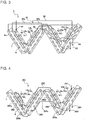
- Fig. 4 is a view illustrating a refrigerant flow passage 80 of a heat exchanger 201 according to Embodiment 2 of the present invention. As illustrated in Fig. 4 , a refrigerant inlet 281 of the heat exchanger 201 may be arranged closer to the back panel 51, i.e., in a heat exchanger block 210d closest to the rear air passage wall.
- a refrigerant inflow passage can be shortened between the heat exchanger 201 and a connection pipe between the indoor unit and the outdoor unit that is a flow passage through which the refrigerant flows. This enables refrigerant pressure loss to be reduced during the cooling operation, thereby improving the cooling performance of the air-conditioning apparatus.
- the amount of copper pipes used for the refrigerant inflow passage can be reduced by shortening the refrigerant inflow passage, thereby reducing the cost.
- the heat exchanger 201 in Embodiment 2 includes a refrigerant flow passage 280 as described below. Firstly, the refrigerant flows into the heat exchanger 201 from the refrigerant inlet 281. The refrigerant delivered from the outdoor unit flows into the heat transfer tube 6 from the refrigerant inlet 281 in the top of the auxiliary heat exchange portion 5d of the heat exchanger block 10d closest to the rear air passage wall.
- the refrigerant that has flowed from the refrigerant inlet 281 passes through the heat transfer tube 6 of the auxiliary heat exchange portion 5d of the heat exchanger block 10d, and then passes sequentially through the auxiliary heat exchange portion 5c of the heat exchanger block 10c, the auxiliary heat exchange portion 5b of the heat exchanger block 10b, and the auxiliary heat exchange portion 5a of the heat exchanger block 10a.
- a bifurcation portion 282 is provided in the heat transfer tube 6 after the auxiliary heat exchange portion 5a.
- the refrigerant flowing out of the auxiliary heat exchange portion 5a branches off into two passages of a refrigerant flow passage 280a and a refrigerant flow passage 280b from the bifurcation portion 282, and flows into the primary heat exchange portion 4a of the heat exchanger block 10a.
- the refrigerant flowing through the refrigerant flow passage 280a flows in the row of the heat transfer tubes 6 on the windward side of the primary heat exchange portion 4a in an upward direction, flows into the row of the heat transfer tubes 6 on the leeward side from the uppermost position of the primary heat exchange portion 4a, flows in the row of the heat transfer tubes 6 on the leeward side to the lowermost position, and then flows out of the primary heat exchange portion 4a.
- the refrigerant in the refrigerant flow passage 280a that has flowed out of the primary heat exchange portion 4a flows into the primary heat exchange portion 4b of the heat exchanger block 10b from the lowermost position thereof, flows in the upward direction, and then flows out of the primary heat exchange portion 4b before the refrigerant reaches the uppermost position.
- the refrigerant flowing through the refrigerant flow passage 280b flows in the row of the heat transfer tubes 6 on the windward side of the primary heat exchange portion 4a in a downward direction, flows out of the heat transfer tube 6 that is located in the lowermost position, and then flows into the primary heat exchange portion 4b of the heat exchanger block 10b.
- the refrigerant in the refrigerant flow passage 280b that has flowed into the primary heat exchange portion 4b flows in the row of the heat transfer tubes 6 on the windward side of the primary heat exchange portion 4b to the uppermost position thereof, and flows into the row of the heat transfer tubes 6 on the leeward side from the uppermost position.
- the refrigerant flowing through the refrigerant flow passage 280b flows in the heat transfer tubes 6 on the leeward side of the primary heat exchange portion 4b in a downward direction, and flows out of the primary heat exchange portion 4b before the refrigerant reaches the lowermost position.
- the refrigerant flow passage 280a and the refrigerant flow passage 280b are converged after the refrigerant flows out of the primary heat exchange portion 4b.
- the refrigerant converged at a converging portion 285 branches off from a bifurcation portion 286 again through a refrigerant flow passage 280c.
- the refrigerant flowing in a refrigerant flow passage 280d and a refrigerant flow passage 280e branched from the bifurcation portion 286 flows into the primary heat exchange portion 4c of the heat exchanger block 10c.
- the refrigerant flowing through the refrigerant flow passage 280d flows into the row of the heat transfer tubes 6 on the windward side of the primary heat exchange portion 4c, is transferred to the row on the leeward side of the primary heat exchange portion 4c from the uppermost position in the downward direction, and flows out of the primary heat exchange portion 4c at the lowermost position.
- the refrigerant that has flowed out of the primary heat exchange portion 4c flows into the lowermost position of the row of the heat transfer tubes 6 on the leeward side of the primary heat exchange portion 4d of the heat exchanger block 10d, flows in the upward direction, and flows out of the refrigerant outlet 283.
- the refrigerant flowing through the refrigerant flow passage 280e flows in the row of the heat transfer tubes 6 on the windward side of the primary heat exchange portion 4c in a downward direction, flows out of the primary heat exchange portion 4c at the lowermost position.
- the refrigerant that has flowed out of the primary heat exchange portion 4c flows into the lowermost position of the row of the heat transfer tubes 6 on the windward side of the primary heat exchange portion 4d of the heat exchanger block 10d, flows in the upward direction, flows into the row of the heat transfer tubes 6 on the leeward side at the uppermost position, flows in the downward direction, and flows out of the refrigerant outlet 284.
- the refrigerant flow passage 280 in the heat exchanger 201 includes the converging portion 285 that converges some or all of the branched refrigerant flow passages.
- the refrigerant flow passage 280 may include the bifurcation portion 286 at which the refrigerant flow passage branches off into the refrigerant flow passages equal in the number of refrigerant flow passages before being converged at the converging portion 285.
- the difference in heat load is generated for each portion of the refrigerant flow passage 280
- the difference in the quality of the refrigerant flowing out of each of the refrigerant flow passage 280a and the refrigerant flow passage 280b can be reduced. Accordingly, the quality of the refrigerant branched in the heat exchanger 201 can be averaged, thereby being capable of reducing the variation in the temperature and humidity distribution of the air that passes through the heat exchanger 201. Furthermore, the risk that dew is condensed on the air-flow-direction control plate 3 arranged in the vicinity of the heat exchanger 201 can be reduced.
- the number of heat exchanger blocks 10 included in the heat exchanger 201 is not limited to four. Furthermore, the number of divided flow passages through which the air that has passed through the heat exchanger 1 passes may be appropriately changed in accordance with the number of heat exchanger blocks 10.
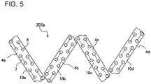
- Fig. 5 is a cross sectional view illustrating a heat exchanger 201a in a modification example of the heat exchanger 201 according to Embodiment 2 of the present invention.
- the auxiliary heat exchange portion 5 does not need to be included in the heat exchanger block 10.
- the number of heat transfer tubes 6 in a row, the number of rows of the heat transfer tubes 6, and the tube diameter of the heat transfer tube 6 are not limited.
- the number of refrigerant inlets 281 and refrigerant outlets 283, 284 are not limited to the number illustrated in Fig. 3 and Fig. 4 .
- the number of flow passages branched at the bifurcation portion 286 after the refrigerant flow passage 280 is converged midway is not limited to the number equal to the number of refrigerant flow passages before being converged at the converging portion 285.
- a reheat dehumidification valve may be provided on the downstream side of the converging portion 285 of the refrigerant flow passage 280.
- the refrigerant flowing in the refrigerant flow passage 280a and the refrigerant flow passage 280b branched from the bifurcation portion 282 can be converged at the converging portion 285 so that the refrigerant can be mixed.
- the difference in heat load is generated for each portion of the refrigerant flow passage 280
- the difference in the quality of the refrigerant flowing out of each of the refrigerant flow passage 280a and the refrigerant flow passage 280b can be reduced.
- the quality of the refrigerant branched in the heat exchanger 201 can be averaged, thereby being capable of reducing the variation in the temperature and humidity distribution of the air that passes through the heat exchanger 201.
- the risk that dew is condensed on the air-flow-direction control plate 3 arranged in the vicinity of the heat exchanger 201 can be reduced.
Landscapes
- Engineering & Computer Science (AREA)
- Chemical & Material Sciences (AREA)
- Combustion & Propulsion (AREA)
- Mechanical Engineering (AREA)
- General Engineering & Computer Science (AREA)
- Physics & Mathematics (AREA)
- Thermal Sciences (AREA)
- Air Filters, Heat-Exchange Apparatuses, And Housings Of Air-Conditioning Units (AREA)
Abstract
Description
- The present invention relates to a structure of a heat exchanger of an indoor unit for an air-conditioning apparatus, and an air-conditioning apparatus including the indoor unit for an air-conditioning apparatus.
- A conventional indoor unit for an air-conditioning apparatus includes devices such as a heat exchanger, a fan, and an air-flow-direction control plate, and a box-shaped casing that houses these devices. The indoor unit allows refrigerant to circulate between the indoor unit and an outdoor unit that are connected to each other by pipes. The heat exchanger causes air flowing through the heat exchanger and the refrigerant flowing through the heat exchanger to reject heat or remove heat therebetween, thereby cooling or heating the air. The cooled or heated air is blown out from an air outlet, to adjust the temperature of air inside a room. For such an indoor unit for an air-conditioning apparatus, as a structure that improves the performance of an air-conditioning apparatus by increasing heat-rejecting efficiency or heat-removing efficiency, a structure has been proposed in which a propeller fan is arranged on the windward side of the heat exchanger.
- According to an indoor unit for an air-conditioning apparatus disclosed in
Patent Literature 1, for example, a propeller fan is arranged on the upstream side of the heat exchanger, and an air outlet is provided in a lower portion of the casing. The heat exchanger includes a single or a plurality of heat exchanger blocks. The air is supplied to the heat exchanger by the propeller fan, and the air that is heat-exchanged and conditioned is blown out from the air outlet. - According to an indoor unit for an air-conditioning apparatus disclosed in
Patent Literature 2, a propeller fan is arranged on the upstream side of the heat exchanger, and an air outlet is provided in a lower portion of the casing. The heat exchanger includes a plurality of heat exchanger blocks, and the heat exchanger blocks are arranged in a reverse V shape in side view. An air mixing promoting element is provided so that the air passing through each of the heat exchanger blocks is mixed. -
- Patent Literature 1:
WO2010/089920 - Patent Literature 2:
WO2016/002015 - However, in the indoor unit for an air-conditioning apparatus disclosed in
Patent Literature 1, since the propeller fan is arranged on the windward side of the heat exchanger, the air that has passed through the heat exchanger is not mixed. Therefore, the variation in blow-off temperature and humidity distribution increases due to the air velocity difference of blown-out air at the air outlet of the indoor unit during cooling operation. When a plurality of refrigerant flow passages and a plurality of refrigerant outlets are provided in the heat exchanger during the cooling operation, the refrigerant at any one of the plurality of refrigerant outlets is brought in a dry state due to the drift of the refrigerant and the difference in the heat load for each refrigerant flow passage, resulting in an increase in temperature of the refrigerant. In this case, the temperature and humidity distribution of the blown-out air further expands. InPatent Literature 2, the air mixing promoting element is provided in the vicinity of the heat exchanger, and the temperature and humidity distribution of the blown-out air is averaged. However, when the air-flow-direction control plate is provided in the vicinity of the heat exchanger, the air mixing promoting element cannot be provided, resulting in dew condensation on the air-flow-direction control plate due to the influence of the wake of the heat exchanger. - The present invention has been made to solve the above-mentioned problems, and an object thereof is to provide an indoor unit for an air-conditioning unit that can suppress dew condensation on an air-flow-direction control plate in a configuration in which the air-flow-direction control plate is arranged in a vicinity of at least one of a plurality of heat exchanger blocks of a heat exchanger, and the air-conditioning unit.
- An indoor unit for an air-conditioning apparatus of an embodiment of the present invention includes a casing, an air inlet provided on the casing, an air outlet opening in a bottom surface of the casing, a heat exchanger arranged in an air passage extending from the air inlet to the air outlet, a fan arranged on a windward side of the heat exchanger in the air passage, and an air-flow-direction control plate provided in the air passage between the heat exchanger and the air outlet, wherein the heat exchanger includes a plurality of heat exchanger blocks that are arranged in a front-and-rear direction of the casing, and includes a refrigerant inlet through which refrigerant flows into the heat exchanger during a cooling operation, and a refrigerant outlet through which the refrigerant flows out of the heat exchanger, the air-flow-direction control plate is provided in the vicinity of one of the heat exchanger blocks, the refrigerant outlet is provided in a heat exchanger block other than the heat exchanger block that is provided in the vicinity of the air-flow-direction control plate, and the number of refrigerant outlets is larger than the number of refrigerant inlets.
- According to an embodiment of the present invention, the heat exchanger of the indoor unit for an air-conditioning apparatus includes a refrigerant outlet that is provided in the heat exchanger block other than the heat exchanger block that is disposed in the vicinity of the air-flow-direction control plate. Thus, the variation in the temperature and humidity distribution of the blown-out air passing through the air-flow-direction control plate can be reduced, even when the refrigerant in the vicinity of the refrigerant outlets is in the dry state. Therefore, the dew condensation on the air-flow-direction control plate can be suppressed.
-
-
Fig. 1 is a perspective view illustrating an indoor unit for an air-conditioning apparatus according toEmbodiment 1 of the present invention. -
Fig. 2 is an explanatory view illustrating a cross section A-A perpendicular to a longitudinal direction of the indoor unit inFig. 1 . -
Fig. 3 is a view illustrating a refrigerant flow passage of aheat exchanger 1 illustrated inFIG. 2 . -
Fig. 4 is a view illustrating a refrigerant flow passage of a heat exchanger according toEmbodiment 2 of the present invention. -
Fig. 5 is a cross sectional view illustrating a heat exchanger in a modification example of the heat exchanger according toEmbodiment 2 of the present invention. - Embodiments of the present invention will be described hereinafter with reference to the drawings. In the drawings, devices denoted by the same reference symbols are the same or corresponding devices, and the same applies throughout the entire text of the specification. Further, the modes of components described in the entire text of the specification are merely illustrative, and the present invention is not limited to those described herein. In particular, combinations of the components are not limited to the combinations in embodiments, and components described in one embodiment may be applied to other embodiments. Furthermore, with regard to a plurality of devices of the same type that are distinguished by suffixes, in a case where the devices are not particularly required to be distinguished or specified, the suffixes are omitted in some cases. In addition, the relationship of sizes of the components in the drawings may differ from the actual sizes.
-
Fig. 1 is a perspective view of anindoor unit 100 of an air-conditioning apparatus according toEmbodiment 1 of the present invention. As illustrated inFig. 1 , theindoor unit 100 includes acasing 50 having a substantially cuboid shape. Thecasing 50 includes afront panel 52 on a front surface of theindoor unit 100. A surface facing thefront panel 52 of thecasing 50 includes aback panel 51. Theindoor unit 100 has theback panel 51 that is attached and fixed to an installation wall surface of a room. Twoair inlets 60 are arranged in a top surface of thecasing 50. Anair outlet 70 is provided in a bottom surface of thecasing 50. -
Fig. 2 is an explanatory view illustrating a cross section A-A perpendicular to a longitudinal direction of theindoor unit 100 ofFig. 1 . The cross section A-A is a cross section taken along the center of an axial-flow fan 2. An internal structure and a flow of air in theindoor unit 100 of the air-conditioning apparatus according toEmbodiment 1 will be described with reference toFig. 2 . Theair inlet 60 is formed in the top surface of thecasing 50, and theair outlet 70 is formed in the bottom surface of thecasing 50. Anair passage 55 extending from theair inlet 60 to theair outlet 70 is formed inside thecasing 50. In theair passage 55, the axial-flow fan 2 is arranged directly below theair inlet 60. The axial-flow fan 2 rotates to suck the air outside thecasing 50 into the inside of theair passage 55 from theair inlet 60. Aheat exchanger 1 is arranged below the axial-flow fan 2. Theheat exchanger 1 includes a plurality ofheat exchanger blocks 10a to 10d arranged in a W shape in cross-section perpendicular to a longitudinal direction of thecasing 50. Theheat exchanger 1 is arranged between thefront panel 52 and theback panel 51, and the air delivered from the axial-flow fan 2 exchanges heat with refrigerant that has passed through theheat exchanger 1 and passes through aheat transfer tube 6. The air heat-exchanged by theheat exchanger 1 is sent toward theair outlet 70. Note that inEmbodiment 1, the heat exchanger blocks 10a to 10d are arranged in a W shape, but the arrangement of theheat exchanger blocks 10a to 10d is not limited to its form. The number of the plurality of heat exchanger blocks 10 is not limited to four. The plurality of heat exchanger blocks 10 are arranged in a front-and-rear direction of thecasing 50, and may be in a form such as an N shape, an M shape, and a V shape, for example. - A
drain pan 20 is arranged below theheat exchanger 1. Thedrain pan 20 includes adrain pan portion 20a and adrain pan portion 20b for receiving dew condensation water attached to theheat exchanger 1. Thedrain pan portions heat exchanger 1 from below, respectively. The air that has passed through theheat exchanger 1 is divided, thereby to flow through divided air passages formed between thedrain pan portion 20a and a frontair passage wall 52a of thefront panel 52, between thedrain pan portion 20a and thedrain pan portion 20b, and between thedrain pan portion 20b and a rearair passage wall 51a of theback panel 51, respectively. The air passage formed between thedrain pan portion 20a and the frontair passage wall 52a of thefront panel 52 is referred to as afront air passage 56a. The air passage formed between thedrain pan portion 20a and thedrain pan portion 20b is referred to as acentral air passage 56b. The air passage formed between thedrain pan portion 20b and a rearair passage wall 51a of theback panel 51 is referred to as arear air passage 56c. Thefront air passage 56a, thecentral air passage 56b, and therear air passage 56c inEmbodiment 1 correspond to the "divided air passages" of the present invention. - The air that has passed through the
heat exchanger block 10a of theheat exchanger 1 mainly passes through thefront air passage 56a, theheat exchanger block 10a being the closest to thefront panel 52. An air-flow-direction control plate 3 is disposed in thefront air passage 56a. The air-flow-direction control plate 3 is formed in a thin-plate shape, and the plate-shaped flat portion of the air-flow-direction control plate 3 is normally disposed to be in parallel to a direction of air flowing in thefront air passage 56a. A plurality of air-flow-direction control plates 3 are disposed along the front air passage 56 extending in the longitudinal direction of the casing 50a. The air-flow-direction control plate 3 changes the angle of the flat portion to change the direction of air to be blown out from theair outlet 70. Note that thefront air passage 56a inEmbodiment 1 corresponds to a "first divided air passage" in the present invention. In addition, theheat exchanger block 10a corresponds to a "first heat exchanger block" in the present invention. That is, the divided air passage into which the air that has passed through the "first heat exchanger block" flows corresponds to the "first divided air passage," and the plurality of air-flow-direction control plates 3 are disposed in the first divided air passage. - The air that has passed through the heat exchanger blocks 10b and 10c at the center of the
heat exchanger 1 mainly passes through thecentral air passage 56b.Baffle plates central air passage 56b, and the air passing through thecentral air passage 56b is rectified by thebaffle plates - The air that has passed through the
heat exchanger block 10d of theheat exchanger 1 mainly passes through therear air passage 56c, theheat exchanger block 10d being the closest to theback panel 51. The rearair passage wall 51a has an upper portion that is parallel to the back surface of thecasing 50, and a lower portion of the rearair passage wall 51a is formed to extend downward below theheat exchanger 1. A lower end of the rearair passage wall 51a is disposed below the apex disposed closer to the back panel among the two lower apexes of the W-shape of theheat exchanger 1. The air passing through therear air passage 56c passes along therear air passage 56c, thereby being rectified to flow obliquely downward toward the front of thecasing 50. - The
air outlet 70 is provided below thedrain pan 20. Theair outlet 70 is closed by an up-and-downairflow direction louver 30 closer to the front surface and an up-and-downairflow direction louver 40 closer to the back surface during operation of an operation. As illustrated inFig. 2 , during the operation, the up-and-downairflow direction louvers respective rotation shafts air outlet 70. The airflow direction can be changed to the up-and-down direction by adjusting the angles of the up-and-downairflow direction louver 30 closer to the front surface and the up-and-downairflow direction louver 40 closer to the back surface. The up-and-downairflow direction louver 30 closer to the front surface is provided with a right-and-left airflow direction louver 35 by which the airflow direction is changed to the right-and-left direction. The right-and-left airflow direction louver 35 changes the angle to a right-and-left direction of thecasing 50 to change the airflow direction. -
Fig. 3 is a view illustrating arefrigerant flow passage 80 of theheat exchanger 1 illustrated inFIG. 2 . Theheat exchanger 1 includes a plurality of heat exchanger blocks 10a to 10d arranged in a W shape, in a cross-section perpendicular to a longitudinal direction of thecasing 50. The heat exchanger blocks 10a to 10d each include a primary heat exchange portion 4 and an auxiliary heat exchange portion 5. The auxiliary heat exchange portion 5 is arranged so as to be overlapped with the windward side of the primary heat exchange portion 4. Note that the windward side means an upstream side of the air flow generated by the rotation of the axial-flow fan 2. The leeward side means a downstream side of the air flow generated by the rotation of the axial-flow fan 2. The auxiliary heat exchange portion 5 is arranged to mainly increase a subcooled region during heating operation to thereby improve the heat exchange performance. The primary heat exchange portion 4 and the auxiliary heat exchange portion 5 each include theheat transfer tubes 6 each configured to extend linearly in the longitudinal direction of thecasing 50 and be turned back at the end thereof, andfins 7 each are a thin strip-shaped metal plate. A plurality offins 7 are arranged at fine intervals in the longitudinal direction of thecasing 50, i.e., in a direction in which theheat transfer tubes 6 extend linearly. Thefin 7 has holes therein through which theheat transfer tubes 6 pass, and is assembled so that theheat transfer tubes 6 pass through the holes. - The
heat transfer tube 6 is turned back a plurality of number of times at the ends in the longitudinal direction of theheat exchanger 1 to form therefrigerant flow passage 80. InEmbodiment 1, the primary heat exchange portion 4 includes theheat transfer tubes 6 that are arrayed in two rows on the windward side and the leeward side in a plane so that the two rows are arranged in parallel to each other, and theheat transfer tubes 6 arrayed in the plane are connected at their ends. For example, the plurality ofheat transfer tubes 6 arrayed on the cross section illustrated inFig. 3 are connected to one another at their ends by U-shaped connecting tubes. InEmbodiment 1, the auxiliary heat exchange portion 5 includes theheat transfer tubes 6 that are arrayed in a single row in a plane. InFig. 3 , a dotted line connecting the adjacentheat transfer tubes 6 indicates that the adjacentheat transfer tubes 6 are connected to each other at the ends on the rear side of theheat exchanger 1 as shown inFig. 3 . InFig. 3 , a solid line connecting the adjacentheat transfer tubes 6 indicates that the adjacentheat transfer tubes 6 are connected to each other at the ends on the front side ofFig. 3 of theheat exchanger 1 as shown inFig. 3 . - In the
heat exchanger 1 illustrated inFig. 3 , during a cooling operation, the auxiliary heat exchange portion 5 is located on the upstream side of therefrigerant flow passage 80 and the primary heat exchange portion 4 is located on the downstream side of therefrigerant flow passage 80. The refrigerant delivered from the outdoor unit flows into theheat transfer tube 6 from arefrigerant inlet 81 in the top of an auxiliaryheat exchange portion 5a of theheat exchanger block 10a closest to thefront panel 52. The refrigerant that has flowed from therefrigerant inlet 81 passes through theheat transfer tube 6 of the auxiliaryheat exchange portion 5a of theheat exchanger block 10a, and then passes sequentially through an auxiliaryheat exchange portion 5b of theheat exchanger block 10b, an auxiliaryheat exchange portion 5c of theheat exchanger block 10c, and an auxiliaryheat exchange portion 5d of theheat exchanger block 10d. Therefrigerant flow passage 80 is provided with abifurcation portion 82 after the refrigerant flows out of the auxiliaryheat exchange portion 5d. The refrigerant flowing out of the auxiliaryheat exchange portion 5d branches off into two passages of arefrigerant flow passage 80a and arefrigerant flow passage 80b from thebifurcation portion 82. The refrigerant flowing in the onerefrigerant flow passage 80a flows into a primaryheat exchange portion 4a of theheat exchanger block 10a closest to thefront panel 52. The refrigerant flowing in the otherrefrigerant flow passage 80b flows into a primaryheat exchange portion 4b of theheat exchanger block 10b that is closer to thefront panel 52 among the central heat exchanger blocks. - The refrigerant that has branched off into the
refrigerant flow passage 80a flows into the primaryheat exchange portion 4a of theheat exchanger block 10a. In the primaryheat exchange portion 4a, the refrigerant flows into aheat transfer tube 6a that is located in the uppermost position among theheat transfer tubes 6 arrayed on the windward side. The primaryheat exchange portion 4a includes theheat transfer tubes 6 that are arrayed in two rows on the windward side and the leeward side. The refrigerant that has flowed into the primaryheat exchange portion 4a passes through the row of theheat transfer tubes 6 on the windward side and the row of theheat transfer tubes 6 on the leeward side, and then flows out of the primaryheat exchange portion 4a. The refrigerant that has flowed out of the primaryheat exchange portion 4a flows into a primaryheat exchange portion 4c of theheat exchanger block 10c. The refrigerant that has flowed into the primaryheat exchange portion 4c of theheat exchanger block 10c flows into theheat transfer tube 6 that is located in the uppermost position on the windward side of the primaryheat exchange portion 4c. In the primaryheat exchange portion 4a, the refrigerant flows into theheat transfer tube 6 that is located in the uppermost position on the leeward side after the refrigerant has passed through the secondheat transfer tube 6 from top on the windward side, and then the refrigerant flows into the thirdheat transfer tube 6 from the top on the windward side after the refrigerant has passed through the secondheat transfer tube 6 from top on the leeward side. Then, the refrigerant passes through theheat transfer tubes 6 that are located below the thirdheat transfer tube 6 from the top on the windward side of the primaryheat exchange portion 4c, and then flows out of theheat transfer tube 6 that is located in the lowermost position on the windward side of the primaryheat exchange portion 4c. Then, the refrigerant flows into the primaryheat exchange portion 4d of theheat exchanger block 10d closest to theback panel 51. The refrigerant that has flowed into the primaryheat exchange portion 4d flows into theheat transfer tube 6 that is located in the lowermost position on the windward side, passes through theheat transfer tubes 6 that are located in a lower portion on the windward side, flows into the row of theheat transfer tubes 6 on the leeward side, and then flows out of arefrigerant outlet 83 that is provided at the center of theheat transfer tube 6 on the leeward side. - The refrigerant that has branched off into the
refrigerant flow passage 80b from thebifurcation portion 82 flows into the primaryheat exchange portion 4b of theheat exchanger block 10b. In the primaryheat exchange portion 4b, the refrigerant flows into theheat transfer tube 6b that is located in the uppermost position among theheat transfer tubes 6 arrayed on the windward side. The primaryheat exchange portion 4b includes theheat transfer tubes 6 that are arrayed in two rows on the windward side and the leeward side. The refrigerant that has flowed into the primaryheat exchange portion 4b passes through the row of theheat transfer tubes 6 on the windward side and the row of theheat transfer tubes 6 on the leeward side, and then flows out of the primaryheat exchange portion 4b. The refrigerant that has flowed out of the primaryheat exchange portion 4b flows into the primaryheat exchange portion 4d of theheat exchanger block 10d. The refrigerant that has flowed into the primaryheat exchange portion 4d of theheat exchanger block 10d flows into theheat transfer tube 6 that is located in the uppermost position on the windward side of the primaryheat exchange portion 4d. The refrigerant that has flowed into theheat transfer tube 6 located in the upper most portion on the windward side of the primaryheat exchange portion 4d flows into theheat transfer tube 6 that is located in the uppermost position on the leeward side after the refrigerant has passed through the secondheat transfer tube 6 from top on the windward side, and then the refrigerant flows into the thirdheat transfer tube 6 from the top on the windward side after the refrigerant has passed through the secondheat transfer tube 6 from top on the leeward side. Then, the refrigerant passes through the third and fourthheat transfer tubes 6 from the top on the windward side of the primaryheat exchange portion 4d, and then flows out of the primaryheat exchange portion 4d. Then, the refrigerant that has flowed out of the primaryheat exchange portion 4d flows into the thirdheat transfer tube 6 from the top on the leeward side of the primaryheat exchange portion 4c. Then, the refrigerant flows from the thirdheat transfer tube 6 on the leeward side of the primaryheat exchange portion 4c to theheat transfer tube 6 on the lowermost position, and flows out of the primaryheat exchange portion 4c. The refrigerant that has flowed out of the primaryheat exchange portion 4c flows into theheat transfer tube 6 located in the lowermost position on the leeward side of the primaryheat exchange portion 4d of theheat exchanger block 10d closest to theback panel 51. The refrigerant that has flowed into the primaryheat exchange portion 4d flows into theheat transfer tube 6 located in the lowermost position on the windward side, passes through theheat transfer tubes 6 that are located in a lower portion on the windward side, is transferred to theheat transfer tube 6 on the leeward side, and then flows out of arefrigerant outlet 84. - As described above, during the cooling operation, the refrigerant flowing into the
heat exchanger 1 flows into theheat exchanger 1 from a single refrigerant circuit, and therefrigerant flow passage 80 branches off midway into two refrigerant circuits of therefrigerant flow passage 80a and therefrigerant flow passage 80b, and flows out of therefrigerant outlet 83 and therefrigerant outlet 84. Here, the tworefrigerant outlets heat transfer tubes 6 in the row on the most leeward side of theheat transfer tubes 6 in theheat exchanger block 10d closest to theback panel 51 of the heat exchanger blocks included in the primary heat exchange portion 4 and the auxiliary heat exchange portion 5 of theheat exchanger 1. - Since the drift of the refrigerant occurs in the
refrigerant flow passage 80 of theheat exchanger 1 and the difference in heat load is generated for each portion of therefrigerant flow passage 80, the refrigerant may be dried in therefrigerant outlet 83 and therefrigerant outlet 84. Therefore, this may cause increase in the variation in the temperature and humidity distribution of the air that passes through theheat exchanger 1 and is blown into the air-flow-direction control plate 3. However, therefrigerant outlet 83 and therefrigerant outlet 84 through which the refrigerant flows out of theheat exchanger 1 are not arranged in theheat exchanger block 10a during the cooling operation, theheat exchanger block 10a being disposed on the windward side of the air-flow-direction control plate 3, thereby enabling the air-flow-direction control plate 3 to be arranged at a position near theheat exchanger 1 affected by the wake of the heat transfer tubes. InEmbodiment 1, in thefront air passage 56a into which the air that has passed through theheat exchanger block 10a flows, the variation in the temperature and humidity distribution of the air that passes through the air-flow-direction control plate 3 is not increased. Therefore, dew condensation on the air-flow-direction control plate 3 during the cooling operation can be suppressed. - To prevent dew from being condensed on the air-flow-
direction control plate 3, the heat exchanger block 10 in which therefrigerant outlet 83 and therefrigerant outlet 84 are arranged does not have to be theheat exchanger block 10d closest to the back panel for cooling operation, and may be theheat exchanger block direction control plate 3, for example. This is because the air that has passed through theheat exchanger block 10b and theheat exchanger block 10c mainly passes through thecentral air passage 56b, and therefore the variation in the quality of the refrigerant in therefrigerant outlet 83 and therefrigerant outlet 84 has less effect on the air-flow-direction control plate 3 that is disposed in thefront air passage 56a. Furthermore, a detector may be provided to detect the quality of the refrigerant in therefrigerant outlet 83 and therefrigerant outlet 84. For example, the detector may detect the temperatures of pipes at therefrigerant outlet 83 and therefrigerant outlet 84. - The
indoor unit 100 of an air-conditioning apparatus in which theheat exchanger 1 is provided is connected with an outdoor unit. The outdoor unit is provided with a compressor and an outdoor heat exchanger. Theindoor unit 100 and the outdoor unit are connected to each other by a connection pipe through which the refrigerant flows to form a refrigeration cycle circuit. -
- (1) The
indoor unit 100 of an air-conditioning apparatus according toEmbodiment 1 includes thecasing 50, theair inlet 60 provided on thecasing 50, theair outlet 70 opening in a bottom surface of thecasing 50, theheat exchanger 1 arranged in theair passage 55 extending from theair inlet 60 to theair outlet 70, the axial-flow fan 2 arranged on the windward side of theheat exchanger 1 in theair passage 55, and the air-flow-direction control plate 3 provided in theair passage 55 between theheat exchanger 1 and theair outlet 70. Theheat exchanger 1 includes a plurality of heat exchanger blocks 10 that are arranged in the front-and-rear direction of the casing, and includes therefrigerant inlet 81 through which the refrigerant flows into theheat exchanger 1, and therefrigerant outlets heat exchanger 1. The air-flow-direction control plate 3 is provided in the vicinity of one of the heat exchanger blocks 10, therefrigerant outlets heat exchanger block 10d other than theheat exchanger block 10a that is provided in the vicinity of the air-flow-direction control plate, and the number ofrefrigerant outlets refrigerant inlets 81.
Such a configuration can suppress condensation of dew on the air-flow-direction control plate 3 even when the air-flow-direction control plate 3 is provided in the vicinity of theheat exchanger block 10a. When components such as the air-flow-direction control plate 3 are arranged in the vicinity of the heat exchanger block 10, dew concentration may be normally caused by differences in temperature and humidity of the air that has passed through each portion of theheat exchanger block 10a. The variation in temperature and humidity distribution of the air that has passed through theheat exchanger block 10d provided with therefrigerant outlets heat exchanger 1, but the air that has passed through theheat exchanger block 10d does not pass through the air-flow-direction control plate 3. Since the air-flow-direction control plate 3 is arranged in the vicinity of theheat exchanger block 10a, the variation in temperature and humidity of the air in contact with the air-flow-direction control plate 3 is relatively small, and hence, the dew is hardly condensed on the air-flow-direction control plate 3. Note that inEmbodiment 1, the heat exchanger block 10 provided in the vicinity of the air-flow-direction control plate 3 is theheat exchanger block 10a, and the heat exchanger block 10 provided with therefrigerant outlets heat exchanger block 10d, but the present invention is not limited to the embodiment. The heat exchanger block 10 provided in the vicinity of the air-flow-direction control plate 3 and the heat exchanger block 10 provided with therefrigerant outlets - (2) In the
indoor unit 100 of an air-conditioning apparatus according toEmbodiment 1, theair passage 55 is divided into a plurality of divided air passages on the downstream side of theheat exchanger 1. The air that has passed through theheat exchanger block 10a provided with norefrigerant outlets front air passage 56a that is one of the divided air passages, and the air-flow-direction control plate 3 is disposed in thefront air passage 56a. Note that theheat exchanger block 10a inEmbodiment 1 corresponds to a "first heat exchanger block" of the present invention, and thefront air passage 56a inEmbodiment 1 corresponds to a "first divided air passage" of the present invention.
With such a configuration, the air that has passed through theheat exchanger block 10a provided with norefrigerant outlets front air passage 56a in which the air-flow-direction control plate 3 is disposed, and therefore the air-flow-direction control plate 3 is arranged so that dew is hardly condensed on the air-flow-direction control plate 3. Note that the "first heat exchanger block" of the present invention is not limited to theheat exchanger block 10a, and may be the other heat exchanger block 10 provided with norefrigerant outlets front air passage 56a. When the "first heat exchanger block" corresponds to theheat exchanger block central air passage 56b. When the "first heat exchanger block" corresponds to theheat exchanger block 10d, the "first divided air passage" corresponds to therear air passage 56c. - (3) In the
indoor unit 100 of an air-conditioning apparatus according toEmbodiment 1, the heat exchanger block 10 includes the auxiliary heat exchange portion 5 and the primary heat exchange portion 4. The auxiliary heat exchange portion 5 is arranged so as to be overlapped on the windward side of the primary heat exchange portion 4 in theair passage 55. Therefrigerant inlet 81 is provided in the auxiliary heat exchange portion 5. Therefrigerant outlets - (4) The
indoor unit 100 of an air-conditioning apparatus according toEmbodiment 1 further includes a detector for detecting the dry state of the refrigerant in therefrigerant outlets
With such a configuration, the dry state of the refrigerant in therefrigerant outlets heat exchanger 1 is detected to adjust the opening degree of the expansion valve of the outdoor unit, and therefore the dry state of therefrigerant outlets - (5) An air-conditioning apparatus according to
Embodiment 1 includes an outdoor unit for an air-conditioning apparatus that includes a compressor configured to compress the refrigerant, and theindoor unit 100 of the air-conditioning apparatus according toEmbodiment 1, to thereby constitute a refrigeration cycle in which the refrigerant circulates between the outdoor unit for an air-conditioning apparatus and theindoor unit 100 of the air-conditioning apparatus. - With such a configuration, even when the drift of the refrigerant occurs in the
refrigerant flow passage 80 of theheat exchanger 1 of theindoor unit 100, theindoor unit 100 includes the configurations (1) to (4) described above, thereby being capable of suppressing dew condensation on the components such as the air-flow-direction control plate 3 arranged in the vicinity of the heat exchanger block 10. - An
indoor unit 200 of an air-conditioning apparatus according toEmbodiment 2 is obtained by modifying the structure of therefrigerant flow passage 80 of theheat exchanger 1 in theindoor unit 100 of an air-conditioning apparatus according toEmbodiment 1. The following description is focused on differences betweenEmbodiment 2 andEmbodiment 1. Matters that are not particularly mentioned inEmbodiment 2 are similar to those inEmbodiment 1, and the same functions and components as those inEmbodiment 1 are designated by the same reference signs in the following description. -
Fig. 4 is a view illustrating arefrigerant flow passage 80 of aheat exchanger 201 according toEmbodiment 2 of the present invention. As illustrated inFig. 4 , arefrigerant inlet 281 of theheat exchanger 201 may be arranged closer to theback panel 51, i.e., in a heat exchanger block 210d closest to the rear air passage wall. When all of therefrigerant inlet 281 andrefrigerant outlets heat exchanger 201 are arranged in the same heat exchanger block 210d closest to the rear air passage wall, a refrigerant inflow passage can be shortened between theheat exchanger 201 and a connection pipe between the indoor unit and the outdoor unit that is a flow passage through which the refrigerant flows. This enables refrigerant pressure loss to be reduced during the cooling operation, thereby improving the cooling performance of the air-conditioning apparatus. The amount of copper pipes used for the refrigerant inflow passage can be reduced by shortening the refrigerant inflow passage, thereby reducing the cost. - As illustrated in
Fig. 4 , theheat exchanger 201 inEmbodiment 2 includes arefrigerant flow passage 280 as described below. Firstly, the refrigerant flows into theheat exchanger 201 from therefrigerant inlet 281. The refrigerant delivered from the outdoor unit flows into theheat transfer tube 6 from therefrigerant inlet 281 in the top of the auxiliaryheat exchange portion 5d of theheat exchanger block 10d closest to the rear air passage wall. The refrigerant that has flowed from therefrigerant inlet 281 passes through theheat transfer tube 6 of the auxiliaryheat exchange portion 5d of theheat exchanger block 10d, and then passes sequentially through the auxiliaryheat exchange portion 5c of theheat exchanger block 10c, the auxiliaryheat exchange portion 5b of theheat exchanger block 10b, and the auxiliaryheat exchange portion 5a of theheat exchanger block 10a. Abifurcation portion 282 is provided in theheat transfer tube 6 after the auxiliaryheat exchange portion 5a. The refrigerant flowing out of the auxiliaryheat exchange portion 5a branches off into two passages of arefrigerant flow passage 280a and arefrigerant flow passage 280b from thebifurcation portion 282, and flows into the primaryheat exchange portion 4a of theheat exchanger block 10a. - The refrigerant flowing through the
refrigerant flow passage 280a flows in the row of theheat transfer tubes 6 on the windward side of the primaryheat exchange portion 4a in an upward direction, flows into the row of theheat transfer tubes 6 on the leeward side from the uppermost position of the primaryheat exchange portion 4a, flows in the row of theheat transfer tubes 6 on the leeward side to the lowermost position, and then flows out of the primaryheat exchange portion 4a. The refrigerant in therefrigerant flow passage 280a that has flowed out of the primaryheat exchange portion 4a flows into the primaryheat exchange portion 4b of theheat exchanger block 10b from the lowermost position thereof, flows in the upward direction, and then flows out of the primaryheat exchange portion 4b before the refrigerant reaches the uppermost position. - The refrigerant flowing through the
refrigerant flow passage 280b flows in the row of theheat transfer tubes 6 on the windward side of the primaryheat exchange portion 4a in a downward direction, flows out of theheat transfer tube 6 that is located in the lowermost position, and then flows into the primaryheat exchange portion 4b of theheat exchanger block 10b. The refrigerant in therefrigerant flow passage 280b that has flowed into the primaryheat exchange portion 4b flows in the row of theheat transfer tubes 6 on the windward side of the primaryheat exchange portion 4b to the uppermost position thereof, and flows into the row of theheat transfer tubes 6 on the leeward side from the uppermost position. The refrigerant flowing through therefrigerant flow passage 280b flows in theheat transfer tubes 6 on the leeward side of the primaryheat exchange portion 4b in a downward direction, and flows out of the primaryheat exchange portion 4b before the refrigerant reaches the lowermost position. - The
refrigerant flow passage 280a and therefrigerant flow passage 280b are converged after the refrigerant flows out of the primaryheat exchange portion 4b. The refrigerant converged at a convergingportion 285 branches off from abifurcation portion 286 again through arefrigerant flow passage 280c. The refrigerant flowing in arefrigerant flow passage 280d and arefrigerant flow passage 280e branched from thebifurcation portion 286 flows into the primaryheat exchange portion 4c of theheat exchanger block 10c. The refrigerant flowing through therefrigerant flow passage 280d flows into the row of theheat transfer tubes 6 on the windward side of the primaryheat exchange portion 4c, is transferred to the row on the leeward side of the primaryheat exchange portion 4c from the uppermost position in the downward direction, and flows out of the primaryheat exchange portion 4c at the lowermost position. The refrigerant that has flowed out of the primaryheat exchange portion 4c flows into the lowermost position of the row of theheat transfer tubes 6 on the leeward side of the primaryheat exchange portion 4d of theheat exchanger block 10d, flows in the upward direction, and flows out of therefrigerant outlet 283. - The refrigerant flowing through the
refrigerant flow passage 280e flows in the row of theheat transfer tubes 6 on the windward side of the primaryheat exchange portion 4c in a downward direction, flows out of the primaryheat exchange portion 4c at the lowermost position. The refrigerant that has flowed out of the primaryheat exchange portion 4c flows into the lowermost position of the row of theheat transfer tubes 6 on the windward side of the primaryheat exchange portion 4d of theheat exchanger block 10d, flows in the upward direction, flows into the row of theheat transfer tubes 6 on the leeward side at the uppermost position, flows in the downward direction, and flows out of therefrigerant outlet 284. - As described above, the
refrigerant flow passage 280 in theheat exchanger 201 includes the convergingportion 285 that converges some or all of the branched refrigerant flow passages. Furthermore, therefrigerant flow passage 280 may include thebifurcation portion 286 at which the refrigerant flow passage branches off into the refrigerant flow passages equal in the number of refrigerant flow passages before being converged at the convergingportion 285. With such a configuration, the refrigerant flowing in therefrigerant flow passage 280a and therefrigerant flow passage 280b branched from thebifurcation portion 282 are converged at the convergingportion 285 so that the refrigerant is mixed. In the case where the difference in heat load is generated for each portion of therefrigerant flow passage 280, the difference in the quality of the refrigerant flowing out of each of therefrigerant flow passage 280a and therefrigerant flow passage 280b can be reduced. Accordingly, the quality of the refrigerant branched in theheat exchanger 201 can be averaged, thereby being capable of reducing the variation in the temperature and humidity distribution of the air that passes through theheat exchanger 201. Furthermore, the risk that dew is condensed on the air-flow-direction control plate 3 arranged in the vicinity of theheat exchanger 201 can be reduced. - Note that the number of heat exchanger blocks 10 included in the
heat exchanger 201 is not limited to four. Furthermore, the number of divided flow passages through which the air that has passed through theheat exchanger 1 passes may be appropriately changed in accordance with the number of heat exchanger blocks 10. -
Fig. 5 is a cross sectional view illustrating aheat exchanger 201a in a modification example of theheat exchanger 201 according toEmbodiment 2 of the present invention. As illustrated inFig. 5 , in theheat exchanger 201a, the auxiliary heat exchange portion 5 does not need to be included in the heat exchanger block 10. Regarding the primary heat exchange portion 4 and the auxiliary heat exchange portion 5 included in the heat exchanger block 10, the number ofheat transfer tubes 6 in a row, the number of rows of theheat transfer tubes 6, and the tube diameter of theheat transfer tube 6 are not limited. InEmbodiments refrigerant inlets 281 andrefrigerant outlets Fig. 3 and Fig. 4 . The number of flow passages branched at thebifurcation portion 286 after therefrigerant flow passage 280 is converged midway is not limited to the number equal to the number of refrigerant flow passages before being converged at the convergingportion 285. Furthermore, a reheat dehumidification valve may be provided on the downstream side of the convergingportion 285 of therefrigerant flow passage 280. -
- (6) In the
indoor unit 200 of an air-conditioning apparatus according toEmbodiment 2, therefrigerant inlet 281 and therefrigerant outlets heat exchanger block 10d closest to the rear air passage wall.
With such a configuration, a refrigerant inflow passage can be shortened between theheat exchanger 201 and a connection pipe between the outdoor unit and theindoor unit 100. This enables refrigerant pressure loss to be reduced during the cooling operation, thereby improving the cooling performance of the air-conditioning apparatus. The amount of copper pipe used can be reduced by shortening the refrigerant inflow passage, thereby reducing the cost. - (7) In the
indoor unit 200 of an air-conditioning apparatus according toEmbodiment 2, theheat exchanger 201 includes the convergingportion 285 at which at least one of therefrigerant flow passages refrigerant flow passage 280 continuous from therefrigerant inlet 281 to therefrigerant outlets bifurcation portion 286 that is provided on the downstream side of the flow of the refrigerant with respect to the convergingportion 285, at which the refrigerant branches off into therefrigerant flow passages bifurcation portion 286 being greater than or equal to the number of refrigerant flow passages before being converged at the convergingportion 285. - With such a configuration, the refrigerant flowing in the
refrigerant flow passage 280a and therefrigerant flow passage 280b branched from thebifurcation portion 282 can be converged at the convergingportion 285 so that the refrigerant can be mixed. Thus, in the case where the difference in heat load is generated for each portion of therefrigerant flow passage 280, the difference in the quality of the refrigerant flowing out of each of therefrigerant flow passage 280a and therefrigerant flow passage 280b can be reduced. Accordingly, the quality of the refrigerant branched in theheat exchanger 201 can be averaged, thereby being capable of reducing the variation in the temperature and humidity distribution of the air that passes through theheat exchanger 201. Furthermore, the risk that dew is condensed on the air-flow-direction control plate 3 arranged in the vicinity of theheat exchanger 201 can be reduced. - 1 heat exchanger 2 axial-flow fan 3 air-flow-direction control plate 4 primary heat exchange portion 4a primary heat exchange portion 4b primary heat exchange portion 4c primary heat exchange portion 4d primary heat exchange portion 5 auxiliary heat exchange portion 5a auxiliary heat exchange portion 5b auxiliary heat exchange portion 5c auxiliary heat exchange portion 5d auxiliary heat exchange portion 6 heat transfer tube 6a heat transfer tube 6b heat transfer tube 7 fin 10 heat exchanger block 10a heat exchanger block 10b heat exchanger block 10c heat exchanger block 10d heat exchanger block 20 drain pan 20a drain pan portion 20b drain pan portion 21a baffle plate 21b baffle plate 30 up-and-down airflow direction louver closer to front surface 31 rotation shaft 35 right-and-left airflow direction louver 40 up-and-down airflow direction louver closer to back surface 41 rotation shaft 50 casing 51 back panel 51a rear air passage wall 52 front panel 52a front air passage wall 55 air passage 56 front air passage 56a front air passage 56b central air passage 56c rear air passage 60 air inlet 70 air outlet 80 refrigerant flow passage 80a refrigerant flow passage 80b refrigerant flow passage 81 refrigerant inlet 82 bifurcation portion 83 refrigerant outlet 84 refrigerant outlet 100 indoor unit 200 indoor unit 201 heat exchanger 201a heat exchanger 280 refrigerant flow passage 280a refrigerant flow passage 280b refrigerant flow passage 280c refrigerant flow passage 280d refrigerant flow passage 280e refrigerant flow passage 281 refrigerant inlet 282 bifurcation portion 283 refrigerant outlet 284 refrigerant outlet 285 converging portion 286 bifurcation portion
Claims (7)
- An indoor unit for an air-conditioning apparatus comprising:a casing;an air inlet provided on the casing;an air outlet opening in a bottom surface of the casing;a heat exchanger arranged in an air passage extending from the air inlet to the air outlet;a fan arranged on a windward side of the heat exchanger in the air passage; andan air-flow-direction control plate provided in the air passage between the heat exchanger and the air outlet,wherein the heat exchanger comprises a plurality of heat exchanger blocks that are arranged in a front-and-rear direction of the casing, and the heat exchanger includes:a refrigerant inlet through which refrigerant flows into the heat exchanger; anda refrigerant outlet through which the refrigerant flows out of the heat exchanger,the air-flow-direction control plate is provided in a vicinity of one of the heat exchanger blocks,the refrigerant outlet is provided in a heat exchanger block other than the heat exchanger block that is provided in a vicinity of the air-flow-direction control plate, andthe number of refrigerant outlets is larger than the number of refrigerant inlets.
- The indoor unit for an air-conditioning apparatus of claim 1, wherein
the air passage branches off into a plurality of divided air passages on a downstream side of the heat exchanger,
air that has passed through a first heat exchanger block without the refrigerant outlet among the plurality of heat exchanger blocks flows into a first divided air passage that is one of the plurality of divided air passages, and
the air-flow-direction control plate is disposed in the first divided air passage. - The indoor unit for an air-conditioning apparatus of claim 1 or 2, wherein
the refrigerant inlet and the refrigerant outlet are provided in a heat exchanger block closest to a rear air passage wall. - The indoor unit for an air-conditioning apparatus of any one of claims 1 to 3, wherein
the heat exchanger includes:a converging portion, at which at least part of the refrigerant flow passages in which the branched refrigerant flows is converged with the refrigerant flow passage extending from the refrigerant inlet to the refrigerant outlet; anda bifurcation portion provided on a downstream side of a flow of the refrigerant relative to the converging portion, at which the refrigerant branches off into refrigerant flow passages again and the number of the refrigerant flow passages is greater than or equal to the number of the refrigerant flow passages before the convergence. - The indoor unit for an air-conditioning apparatus of any one of claims 1 to 4, wherein
the heat exchanger block includes:
an auxiliary heat exchange portion and a primary heat exchange portion; and
the auxiliary heat exchange portion is arranged so as to be overlapped with a windward side of the primary heat exchange portion in the air passage,
the refrigerant inlet is provided in the auxiliary heat exchange portion, and
the refrigerant outlet is provided in the primary heat exchange portion. - The indoor unit for an air-conditioning apparatus of any one of claims 1 to 5, further comprising:
a detector configured to detect a dry state of the refrigerant in the refrigerant outlet. - An air-conditioning apparatus, comprising:an outdoor unit for an air-conditioning apparatus that includes a compressor configured to compress refrigerant; andthe indoor unit for an air-conditioning apparatus of any one of claims 1 to 6,wherein a refrigeration cycle in which the refrigerant circulates between the outdoor unit and the indoor unit is constituted.
Applications Claiming Priority (1)
| Application Number | Priority Date | Filing Date | Title |
|---|---|---|---|
| PCT/JP2016/083168 WO2018087822A1 (en) | 2016-11-09 | 2016-11-09 | Indoor unit for air conditioner, and air conditioner |
Publications (3)
| Publication Number | Publication Date |
|---|---|
| EP3540318A1 true EP3540318A1 (en) | 2019-09-18 |
| EP3540318A4 EP3540318A4 (en) | 2019-11-13 |
| EP3540318B1 EP3540318B1 (en) | 2022-11-09 |
Family
ID=62110551
Family Applications (1)
| Application Number | Title | Priority Date | Filing Date |
|---|---|---|---|
| EP16920971.5A Not-in-force EP3540318B1 (en) | 2016-11-09 | 2016-11-09 | Indoor unit for air conditioner, and air conditioner |
Country Status (5)
| Country | Link |
|---|---|
| US (1) | US20190257532A1 (en) |
| EP (1) | EP3540318B1 (en) |
| JP (1) | JP6745898B2 (en) |
| CN (1) | CN109923348B (en) |
| WO (1) | WO2018087822A1 (en) |
Families Citing this family (7)
| Publication number | Priority date | Publication date | Assignee | Title |
|---|---|---|---|---|
| JP2019015494A (en) * | 2017-07-07 | 2019-01-31 | 三星電子株式会社Samsung Electronics Co.,Ltd. | Heat exchanger, indoor machine and air conditioner |
| CN210861409U (en) * | 2019-11-28 | 2020-06-26 | 广东美的制冷设备有限公司 | Heat exchanger assembly and air conditioner indoor unit having the same |
| DE102020126579A1 (en) | 2020-10-09 | 2022-04-14 | Viessmann Climate Solutions Se | Method of operating a refrigeration cycle device |
| DE102020126580B3 (en) | 2020-10-09 | 2022-01-13 | Viessmann Climate Solutions Se | Refrigeration cycle device and method of operating such a refrigeration cycle device |
| WO2022176149A1 (en) * | 2021-02-19 | 2022-08-25 | 三菱電機株式会社 | Dehumidification device manufacturing method, dehumidification element, and dehumidification device provided with dehumidification element |
| CN113932295B (en) * | 2021-10-12 | 2023-01-13 | 青岛海尔空调器有限总公司 | Indoor cabinet air conditioner and air conditioner |
| US11953215B2 (en) * | 2022-02-03 | 2024-04-09 | Tyco Fire & Security Gmbh | Panel arrangement for HVAC system |
Family Cites Families (19)
| Publication number | Priority date | Publication date | Assignee | Title |
|---|---|---|---|---|
| JP3045159B2 (en) * | 1998-02-27 | 2000-05-29 | ダイキン工業株式会社 | Indoor unit of air conditioner and installation structure of the indoor unit |
| JP2005098648A (en) * | 2003-09-26 | 2005-04-14 | Matsushita Electric Ind Co Ltd | Air conditioner |
| JP4496951B2 (en) * | 2004-12-22 | 2010-07-07 | パナソニック株式会社 | Air conditioner |
| KR20070053549A (en) * | 2005-11-21 | 2007-05-25 | 엘지전자 주식회사 | Indoor unit of air conditioner |
| CN201242225Y (en) * | 2008-06-17 | 2009-05-20 | 海信科龙电器股份有限公司 | Indoor set of air conditioner |
| JP5409544B2 (en) * | 2010-08-04 | 2014-02-05 | 三菱電機株式会社 | Air conditioner indoor unit and air conditioner |
| JP5518013B2 (en) * | 2011-08-18 | 2014-06-11 | 三菱電機株式会社 | Air conditioner indoor unit and air conditioner equipped with the indoor unit |
| JP5750364B2 (en) * | 2011-12-09 | 2015-07-22 | 日立アプライアンス株式会社 | Air conditioner |
| JP5942248B2 (en) * | 2011-12-27 | 2016-06-29 | パナソニックIpマネジメント株式会社 | Refrigeration cycle equipment |
| WO2014091521A1 (en) * | 2012-12-12 | 2014-06-19 | 三菱電機株式会社 | Outdoor unit for air conditioner |
| JP5803898B2 (en) * | 2012-12-27 | 2015-11-04 | ダイキン工業株式会社 | Air conditioner |
| JP6268586B2 (en) * | 2013-02-14 | 2018-01-31 | パナソニックIpマネジメント株式会社 | Air conditioner |
| CN103134355B (en) * | 2013-03-08 | 2016-04-06 | Tcl空调器(中山)有限公司 | Ultrathin heat exchanger and adopt the wall-hanging air conditioner indoor unit of this ultrathin heat exchanger |
| JP6149494B2 (en) * | 2013-04-30 | 2017-06-21 | ダイキン工業株式会社 | Indoor unit for decorative panel and air conditioner |
| JP5959735B2 (en) * | 2013-05-08 | 2016-08-02 | 三菱電機株式会社 | Air conditioner indoor unit and air conditioner |
| JP6371046B2 (en) * | 2013-09-03 | 2018-08-08 | 日立ジョンソンコントロールズ空調株式会社 | Air conditioner and heat exchanger for air conditioner |
| JP6086057B2 (en) * | 2013-11-29 | 2017-03-01 | 株式会社富士通ゼネラル | Heat exchanger |
| JP2015169422A (en) * | 2014-03-11 | 2015-09-28 | 三菱電機株式会社 | Air conditioner indoor unit |
| KR102435203B1 (en) * | 2015-10-20 | 2022-08-24 | 삼성전자주식회사 | Air conditioner and control method thereof |
-
2016
- 2016-11-09 JP JP2018549666A patent/JP6745898B2/en active Active
- 2016-11-09 CN CN201680090592.8A patent/CN109923348B/en active Active
- 2016-11-09 US US16/324,815 patent/US20190257532A1/en not_active Abandoned
- 2016-11-09 EP EP16920971.5A patent/EP3540318B1/en not_active Not-in-force
- 2016-11-09 WO PCT/JP2016/083168 patent/WO2018087822A1/en not_active Ceased
Also Published As
| Publication number | Publication date |
|---|---|
| CN109923348B (en) | 2021-03-12 |
| CN109923348A (en) | 2019-06-21 |
| JPWO2018087822A1 (en) | 2019-06-24 |
| EP3540318A4 (en) | 2019-11-13 |
| EP3540318B1 (en) | 2022-11-09 |
| JP6745898B2 (en) | 2020-08-26 |
| US20190257532A1 (en) | 2019-08-22 |
| WO2018087822A1 (en) | 2018-05-17 |
Similar Documents
| Publication | Publication Date | Title |
|---|---|---|
| EP3540318B1 (en) | Indoor unit for air conditioner, and air conditioner | |
| JP6545277B2 (en) | Outdoor unit of air conditioner | |
| US20130220584A1 (en) | Heat exchanger, and all-in-one air conditioner equipped therewith | |
| US20160138871A1 (en) | Duplex heat exchanger | |
| US9234673B2 (en) | Heat exchanger with subcooling circuit | |
| EP3805687B1 (en) | Refrigerant distributor, heat exchanger, and air conditioner | |
| JP2016038192A (en) | Parallel flow type heat exchanger and air conditioner | |
| US10047962B2 (en) | Indoor unit for air-conditioning apparatus | |
| EP3608618B1 (en) | Heat exchanger and refrigeration cycle device | |
| US10047963B2 (en) | Indoor unit for air-conditioning apparatus | |
| JP2016200338A (en) | Air conditioner | |
| JP6253513B2 (en) | Air conditioner indoor unit | |
| CN111902683A (en) | Heat exchanger and refrigeration cycle device | |
| JP6727398B2 (en) | Heat exchanger and air conditioner | |
| JP2017048953A (en) | Air conditioner | |
| JP6847328B1 (en) | Indoor unit of air conditioner and air conditioner | |
| CN103574774B (en) | Air conditioner | |
| WO2016151655A1 (en) | Air conditioning device and method for determining performance of same | |
| JPWO2019116838A1 (en) | Heat exchange unit and air conditioner equipped with the same | |
| EP3951303A1 (en) | Air conditioner | |
| KR20180080879A (en) | Heat exchanger | |
| CN101523123B (en) | Air conditioner | |
| US20200282799A1 (en) | Ultra-low profile hvac apparatus for a vehicle |
Legal Events
| Date | Code | Title | Description |
|---|---|---|---|
| STAA | Information on the status of an ep patent application or granted ep patent |
Free format text: STATUS: THE INTERNATIONAL PUBLICATION HAS BEEN MADE |
|
| PUAI | Public reference made under article 153(3) epc to a published international application that has entered the european phase |
Free format text: ORIGINAL CODE: 0009012 |
|
| STAA | Information on the status of an ep patent application or granted ep patent |
Free format text: STATUS: REQUEST FOR EXAMINATION WAS MADE |
|
| 17P | Request for examination filed |
Effective date: 20190405 |
|
| AK | Designated contracting states |
Kind code of ref document: A1 Designated state(s): AL AT BE BG CH CY CZ DE DK EE ES FI FR GB GR HR HU IE IS IT LI LT LU LV MC MK MT NL NO PL PT RO RS SE SI SK SM TR |
|
| AX | Request for extension of the european patent |
Extension state: BA ME |
|
| A4 | Supplementary search report drawn up and despatched |
Effective date: 20191014 |
|
| RIC1 | Information provided on ipc code assigned before grant |
Ipc: F24F 1/0014 20190101ALI20191008BHEP Ipc: F24F 1/02 20190101ALI20191008BHEP Ipc: F24F 1/00 20190101AFI20191008BHEP Ipc: F24F 13/08 20060101ALI20191008BHEP Ipc: F24F 1/0067 20190101ALI20191008BHEP Ipc: F24F 13/30 20060101ALI20191008BHEP Ipc: F24F 1/0063 20190101ALI20191008BHEP |
|
| DAV | Request for validation of the european patent (deleted) | ||
| DAX | Request for extension of the european patent (deleted) | ||
| GRAP | Despatch of communication of intention to grant a patent |
Free format text: ORIGINAL CODE: EPIDOSNIGR1 |
|
| STAA | Information on the status of an ep patent application or granted ep patent |
Free format text: STATUS: GRANT OF PATENT IS INTENDED |
|
| INTG | Intention to grant announced |
Effective date: 20220609 |
|
| GRAS | Grant fee paid |
Free format text: ORIGINAL CODE: EPIDOSNIGR3 |
|
| GRAA | (expected) grant |
Free format text: ORIGINAL CODE: 0009210 |
|
| STAA | Information on the status of an ep patent application or granted ep patent |
Free format text: STATUS: THE PATENT HAS BEEN GRANTED |
|
| REG | Reference to a national code |
Ref country code: DE Ref legal event code: R081 Ref document number: 602016076299 Country of ref document: DE Owner name: MITSUBISHI ELECTRIC CORP., JP Free format text: FORMER OWNER: MITSUBISHI ELECTRIC CORPORATION, TOKYO, JP |
|
| AK | Designated contracting states |
Kind code of ref document: B1 Designated state(s): AL AT BE BG CH CY CZ DE DK EE ES FI FR GB GR HR HU IE IS IT LI LT LU LV MC MK MT NL NO PL PT RO RS SE SI SK SM TR |
|
| REG | Reference to a national code |
Ref country code: GB Ref legal event code: FG4D |
|
| REG | Reference to a national code |
Ref country code: CH Ref legal event code: EP Ref country code: AT Ref legal event code: REF Ref document number: 1530607 Country of ref document: AT Kind code of ref document: T Effective date: 20221115 |
|
| REG | Reference to a national code |
Ref country code: DE Ref legal event code: R096 Ref document number: 602016076299 Country of ref document: DE |
|
| REG | Reference to a national code |
Ref country code: IE Ref legal event code: FG4D |
|
| REG | Reference to a national code |
Ref country code: LT Ref legal event code: MG9D |
|
| REG | Reference to a national code |
Ref country code: NL Ref legal event code: MP Effective date: 20221109 |
|
| REG | Reference to a national code |
Ref country code: AT Ref legal event code: MK05 Ref document number: 1530607 Country of ref document: AT Kind code of ref document: T Effective date: 20221109 |
|
| PG25 | Lapsed in a contracting state [announced via postgrant information from national office to epo] |
Ref country code: SE Free format text: LAPSE BECAUSE OF FAILURE TO SUBMIT A TRANSLATION OF THE DESCRIPTION OR TO PAY THE FEE WITHIN THE PRESCRIBED TIME-LIMIT Effective date: 20221109 Ref country code: PT Free format text: LAPSE BECAUSE OF FAILURE TO SUBMIT A TRANSLATION OF THE DESCRIPTION OR TO PAY THE FEE WITHIN THE PRESCRIBED TIME-LIMIT Effective date: 20230309 Ref country code: NO Free format text: LAPSE BECAUSE OF FAILURE TO SUBMIT A TRANSLATION OF THE DESCRIPTION OR TO PAY THE FEE WITHIN THE PRESCRIBED TIME-LIMIT Effective date: 20230209 Ref country code: LT Free format text: LAPSE BECAUSE OF FAILURE TO SUBMIT A TRANSLATION OF THE DESCRIPTION OR TO PAY THE FEE WITHIN THE PRESCRIBED TIME-LIMIT Effective date: 20221109 Ref country code: FI Free format text: LAPSE BECAUSE OF FAILURE TO SUBMIT A TRANSLATION OF THE DESCRIPTION OR TO PAY THE FEE WITHIN THE PRESCRIBED TIME-LIMIT Effective date: 20221109 Ref country code: ES Free format text: LAPSE BECAUSE OF FAILURE TO SUBMIT A TRANSLATION OF THE DESCRIPTION OR TO PAY THE FEE WITHIN THE PRESCRIBED TIME-LIMIT Effective date: 20221109 Ref country code: AT Free format text: LAPSE BECAUSE OF FAILURE TO SUBMIT A TRANSLATION OF THE DESCRIPTION OR TO PAY THE FEE WITHIN THE PRESCRIBED TIME-LIMIT Effective date: 20221109 |
|
| PG25 | Lapsed in a contracting state [announced via postgrant information from national office to epo] |
Ref country code: RS Free format text: LAPSE BECAUSE OF FAILURE TO SUBMIT A TRANSLATION OF THE DESCRIPTION OR TO PAY THE FEE WITHIN THE PRESCRIBED TIME-LIMIT Effective date: 20221109 Ref country code: PL Free format text: LAPSE BECAUSE OF FAILURE TO SUBMIT A TRANSLATION OF THE DESCRIPTION OR TO PAY THE FEE WITHIN THE PRESCRIBED TIME-LIMIT Effective date: 20221109 Ref country code: LV Free format text: LAPSE BECAUSE OF FAILURE TO SUBMIT A TRANSLATION OF THE DESCRIPTION OR TO PAY THE FEE WITHIN THE PRESCRIBED TIME-LIMIT Effective date: 20221109 Ref country code: IS Free format text: LAPSE BECAUSE OF FAILURE TO SUBMIT A TRANSLATION OF THE DESCRIPTION OR TO PAY THE FEE WITHIN THE PRESCRIBED TIME-LIMIT Effective date: 20230309 Ref country code: HR Free format text: LAPSE BECAUSE OF FAILURE TO SUBMIT A TRANSLATION OF THE DESCRIPTION OR TO PAY THE FEE WITHIN THE PRESCRIBED TIME-LIMIT Effective date: 20221109 Ref country code: GR Free format text: LAPSE BECAUSE OF FAILURE TO SUBMIT A TRANSLATION OF THE DESCRIPTION OR TO PAY THE FEE WITHIN THE PRESCRIBED TIME-LIMIT Effective date: 20230210 |
|
| PG25 | Lapsed in a contracting state [announced via postgrant information from national office to epo] |
Ref country code: NL Free format text: LAPSE BECAUSE OF FAILURE TO SUBMIT A TRANSLATION OF THE DESCRIPTION OR TO PAY THE FEE WITHIN THE PRESCRIBED TIME-LIMIT Effective date: 20221109 |
|
| REG | Reference to a national code |
Ref country code: CH Ref legal event code: PL |
|
| REG | Reference to a national code |
Ref country code: BE Ref legal event code: MM Effective date: 20221130 |
|
| PG25 | Lapsed in a contracting state [announced via postgrant information from national office to epo] |
Ref country code: SM Free format text: LAPSE BECAUSE OF FAILURE TO SUBMIT A TRANSLATION OF THE DESCRIPTION OR TO PAY THE FEE WITHIN THE PRESCRIBED TIME-LIMIT Effective date: 20221109 Ref country code: RO Free format text: LAPSE BECAUSE OF FAILURE TO SUBMIT A TRANSLATION OF THE DESCRIPTION OR TO PAY THE FEE WITHIN THE PRESCRIBED TIME-LIMIT Effective date: 20221109 Ref country code: LI Free format text: LAPSE BECAUSE OF NON-PAYMENT OF DUE FEES Effective date: 20221130 Ref country code: EE Free format text: LAPSE BECAUSE OF FAILURE TO SUBMIT A TRANSLATION OF THE DESCRIPTION OR TO PAY THE FEE WITHIN THE PRESCRIBED TIME-LIMIT Effective date: 20221109 Ref country code: DK Free format text: LAPSE BECAUSE OF FAILURE TO SUBMIT A TRANSLATION OF THE DESCRIPTION OR TO PAY THE FEE WITHIN THE PRESCRIBED TIME-LIMIT Effective date: 20221109 Ref country code: CZ Free format text: LAPSE BECAUSE OF FAILURE TO SUBMIT A TRANSLATION OF THE DESCRIPTION OR TO PAY THE FEE WITHIN THE PRESCRIBED TIME-LIMIT Effective date: 20221109 Ref country code: CH Free format text: LAPSE BECAUSE OF NON-PAYMENT OF DUE FEES Effective date: 20221130 |
|
| REG | Reference to a national code |
Ref country code: DE Ref legal event code: R097 Ref document number: 602016076299 Country of ref document: DE |
|
| P01 | Opt-out of the competence of the unified patent court (upc) registered |
Effective date: 20230711 |
|
| PG25 | Lapsed in a contracting state [announced via postgrant information from national office to epo] |
Ref country code: SK Free format text: LAPSE BECAUSE OF FAILURE TO SUBMIT A TRANSLATION OF THE DESCRIPTION OR TO PAY THE FEE WITHIN THE PRESCRIBED TIME-LIMIT Effective date: 20221109 Ref country code: LU Free format text: LAPSE BECAUSE OF NON-PAYMENT OF DUE FEES Effective date: 20221109 Ref country code: AL Free format text: LAPSE BECAUSE OF FAILURE TO SUBMIT A TRANSLATION OF THE DESCRIPTION OR TO PAY THE FEE WITHIN THE PRESCRIBED TIME-LIMIT Effective date: 20221109 |
|
| PLBE | No opposition filed within time limit |
Free format text: ORIGINAL CODE: 0009261 |
|
| STAA | Information on the status of an ep patent application or granted ep patent |
Free format text: STATUS: NO OPPOSITION FILED WITHIN TIME LIMIT |
|
| 26N | No opposition filed |
Effective date: 20230810 |
|
| GBPC | Gb: european patent ceased through non-payment of renewal fee |
Effective date: 20230209 |
|
| PG25 | Lapsed in a contracting state [announced via postgrant information from national office to epo] |
Ref country code: IE Free format text: LAPSE BECAUSE OF NON-PAYMENT OF DUE FEES Effective date: 20221109 |
|
| PG25 | Lapsed in a contracting state [announced via postgrant information from national office to epo] |
Ref country code: SI Free format text: LAPSE BECAUSE OF FAILURE TO SUBMIT A TRANSLATION OF THE DESCRIPTION OR TO PAY THE FEE WITHIN THE PRESCRIBED TIME-LIMIT Effective date: 20221109 Ref country code: FR Free format text: LAPSE BECAUSE OF NON-PAYMENT OF DUE FEES Effective date: 20230109 Ref country code: BE Free format text: LAPSE BECAUSE OF NON-PAYMENT OF DUE FEES Effective date: 20221130 |
|
| PG25 | Lapsed in a contracting state [announced via postgrant information from national office to epo] |
Ref country code: GB Free format text: LAPSE BECAUSE OF NON-PAYMENT OF DUE FEES Effective date: 20230209 |
|
| PG25 | Lapsed in a contracting state [announced via postgrant information from national office to epo] |
Ref country code: GB Free format text: LAPSE BECAUSE OF NON-PAYMENT OF DUE FEES Effective date: 20230209 |
|
| PGFP | Annual fee paid to national office [announced via postgrant information from national office to epo] |
Ref country code: DE Payment date: 20230929 Year of fee payment: 8 |
|
| PG25 | Lapsed in a contracting state [announced via postgrant information from national office to epo] |
Ref country code: HU Free format text: LAPSE BECAUSE OF FAILURE TO SUBMIT A TRANSLATION OF THE DESCRIPTION OR TO PAY THE FEE WITHIN THE PRESCRIBED TIME-LIMIT; INVALID AB INITIO Effective date: 20161109 |
|
| PG25 | Lapsed in a contracting state [announced via postgrant information from national office to epo] |
Ref country code: CY Free format text: LAPSE BECAUSE OF FAILURE TO SUBMIT A TRANSLATION OF THE DESCRIPTION OR TO PAY THE FEE WITHIN THE PRESCRIBED TIME-LIMIT Effective date: 20221109 |
|
| PG25 | Lapsed in a contracting state [announced via postgrant information from national office to epo] |
Ref country code: MK Free format text: LAPSE BECAUSE OF FAILURE TO SUBMIT A TRANSLATION OF THE DESCRIPTION OR TO PAY THE FEE WITHIN THE PRESCRIBED TIME-LIMIT Effective date: 20221109 Ref country code: IT Free format text: LAPSE BECAUSE OF FAILURE TO SUBMIT A TRANSLATION OF THE DESCRIPTION OR TO PAY THE FEE WITHIN THE PRESCRIBED TIME-LIMIT Effective date: 20221109 |
|
| PG25 | Lapsed in a contracting state [announced via postgrant information from national office to epo] |
Ref country code: MC Free format text: LAPSE BECAUSE OF FAILURE TO SUBMIT A TRANSLATION OF THE DESCRIPTION OR TO PAY THE FEE WITHIN THE PRESCRIBED TIME-LIMIT Effective date: 20221109 |
|
| PG25 | Lapsed in a contracting state [announced via postgrant information from national office to epo] |
Ref country code: MC Free format text: LAPSE BECAUSE OF FAILURE TO SUBMIT A TRANSLATION OF THE DESCRIPTION OR TO PAY THE FEE WITHIN THE PRESCRIBED TIME-LIMIT Effective date: 20221109 |
|
| PG25 | Lapsed in a contracting state [announced via postgrant information from national office to epo] |
Ref country code: BG Free format text: LAPSE BECAUSE OF FAILURE TO SUBMIT A TRANSLATION OF THE DESCRIPTION OR TO PAY THE FEE WITHIN THE PRESCRIBED TIME-LIMIT Effective date: 20221109 |
|
| PG25 | Lapsed in a contracting state [announced via postgrant information from national office to epo] |
Ref country code: MT Free format text: LAPSE BECAUSE OF FAILURE TO SUBMIT A TRANSLATION OF THE DESCRIPTION OR TO PAY THE FEE WITHIN THE PRESCRIBED TIME-LIMIT Effective date: 20221109 |
|
| REG | Reference to a national code |
Ref country code: DE Ref legal event code: R119 Ref document number: 602016076299 Country of ref document: DE |
|
| PG25 | Lapsed in a contracting state [announced via postgrant information from national office to epo] |
Ref country code: DE Free format text: LAPSE BECAUSE OF NON-PAYMENT OF DUE FEES Effective date: 20250603 |
|
| PG25 | Lapsed in a contracting state [announced via postgrant information from national office to epo] |
Ref country code: TR Free format text: LAPSE BECAUSE OF FAILURE TO SUBMIT A TRANSLATION OF THE DESCRIPTION OR TO PAY THE FEE WITHIN THE PRESCRIBED TIME-LIMIT Effective date: 20221109 |