EP3540301A2 - Flexible light guide and lighting system - Google Patents
Flexible light guide and lighting system Download PDFInfo
- Publication number
- EP3540301A2 EP3540301A2 EP19159670.9A EP19159670A EP3540301A2 EP 3540301 A2 EP3540301 A2 EP 3540301A2 EP 19159670 A EP19159670 A EP 19159670A EP 3540301 A2 EP3540301 A2 EP 3540301A2
- Authority
- EP
- European Patent Office
- Prior art keywords
- light
- flexible substrate
- light guide
- region
- extraction features
- Prior art date
- Legal status (The legal status is an assumption and is not a legal conclusion. Google has not performed a legal analysis and makes no representation as to the accuracy of the status listed.)
- Granted
Links
Images





Classifications
-
- B—PERFORMING OPERATIONS; TRANSPORTING
- B29—WORKING OF PLASTICS; WORKING OF SUBSTANCES IN A PLASTIC STATE IN GENERAL
- B29C—SHAPING OR JOINING OF PLASTICS; SHAPING OF MATERIAL IN A PLASTIC STATE, NOT OTHERWISE PROVIDED FOR; AFTER-TREATMENT OF THE SHAPED PRODUCTS, e.g. REPAIRING
- B29C39/00—Shaping by casting, i.e. introducing the moulding material into a mould or between confining surfaces without significant moulding pressure; Apparatus therefor
- B29C39/22—Component parts, details or accessories; Auxiliary operations
- B29C39/42—Casting under special conditions, e.g. vacuum
-
- B—PERFORMING OPERATIONS; TRANSPORTING
- B29—WORKING OF PLASTICS; WORKING OF SUBSTANCES IN A PLASTIC STATE IN GENERAL
- B29D—PRODUCING PARTICULAR ARTICLES FROM PLASTICS OR FROM SUBSTANCES IN A PLASTIC STATE
- B29D11/00—Producing optical elements, e.g. lenses or prisms
- B29D11/00663—Production of light guides
-
- B—PERFORMING OPERATIONS; TRANSPORTING
- B64—AIRCRAFT; AVIATION; COSMONAUTICS
- B64D—EQUIPMENT FOR FITTING IN OR TO AIRCRAFT; FLIGHT SUITS; PARACHUTES; ARRANGEMENT OR MOUNTING OF POWER PLANTS OR PROPULSION TRANSMISSIONS IN AIRCRAFT
- B64D11/00—Passenger or crew accommodation; Flight-deck installations not otherwise provided for
-
- G—PHYSICS
- G02—OPTICS
- G02B—OPTICAL ELEMENTS, SYSTEMS OR APPARATUS
- G02B6/00—Light guides; Structural details of arrangements comprising light guides and other optical elements, e.g. couplings
- G02B6/0001—Light guides; Structural details of arrangements comprising light guides and other optical elements, e.g. couplings specially adapted for lighting devices or systems
- G02B6/0011—Light guides; Structural details of arrangements comprising light guides and other optical elements, e.g. couplings specially adapted for lighting devices or systems the light guides being planar or of plate-like form
- G02B6/0013—Means for improving the coupling-in of light from the light source into the light guide
- G02B6/0015—Means for improving the coupling-in of light from the light source into the light guide provided on the surface of the light guide or in the bulk of it
- G02B6/002—Means for improving the coupling-in of light from the light source into the light guide provided on the surface of the light guide or in the bulk of it by shaping at least a portion of the light guide, e.g. with collimating, focussing or diverging surfaces
- G02B6/0021—Means for improving the coupling-in of light from the light source into the light guide provided on the surface of the light guide or in the bulk of it by shaping at least a portion of the light guide, e.g. with collimating, focussing or diverging surfaces for housing at least a part of the light source, e.g. by forming holes or recesses
-
- G—PHYSICS
- G02—OPTICS
- G02B—OPTICAL ELEMENTS, SYSTEMS OR APPARATUS
- G02B6/00—Light guides; Structural details of arrangements comprising light guides and other optical elements, e.g. couplings
- G02B6/0001—Light guides; Structural details of arrangements comprising light guides and other optical elements, e.g. couplings specially adapted for lighting devices or systems
- G02B6/0011—Light guides; Structural details of arrangements comprising light guides and other optical elements, e.g. couplings specially adapted for lighting devices or systems the light guides being planar or of plate-like form
- G02B6/0013—Means for improving the coupling-in of light from the light source into the light guide
- G02B6/0023—Means for improving the coupling-in of light from the light source into the light guide provided by one optical element, or plurality thereof, placed between the light guide and the light source, or around the light source
- G02B6/0031—Reflecting element, sheet or layer
-
- G—PHYSICS
- G02—OPTICS
- G02B—OPTICAL ELEMENTS, SYSTEMS OR APPARATUS
- G02B6/00—Light guides; Structural details of arrangements comprising light guides and other optical elements, e.g. couplings
- G02B6/0001—Light guides; Structural details of arrangements comprising light guides and other optical elements, e.g. couplings specially adapted for lighting devices or systems
- G02B6/0011—Light guides; Structural details of arrangements comprising light guides and other optical elements, e.g. couplings specially adapted for lighting devices or systems the light guides being planar or of plate-like form
- G02B6/0033—Means for improving the coupling-out of light from the light guide
-
- G—PHYSICS
- G02—OPTICS
- G02B—OPTICAL ELEMENTS, SYSTEMS OR APPARATUS
- G02B6/00—Light guides; Structural details of arrangements comprising light guides and other optical elements, e.g. couplings
- G02B6/0001—Light guides; Structural details of arrangements comprising light guides and other optical elements, e.g. couplings specially adapted for lighting devices or systems
- G02B6/0011—Light guides; Structural details of arrangements comprising light guides and other optical elements, e.g. couplings specially adapted for lighting devices or systems the light guides being planar or of plate-like form
- G02B6/0033—Means for improving the coupling-out of light from the light guide
- G02B6/0035—Means for improving the coupling-out of light from the light guide provided on the surface of the light guide or in the bulk of it
- G02B6/004—Scattering dots or dot-like elements, e.g. microbeads, scattering particles, nanoparticles
- G02B6/0041—Scattering dots or dot-like elements, e.g. microbeads, scattering particles, nanoparticles provided in the bulk of the light guide
-
- G—PHYSICS
- G02—OPTICS
- G02B—OPTICAL ELEMENTS, SYSTEMS OR APPARATUS
- G02B6/00—Light guides; Structural details of arrangements comprising light guides and other optical elements, e.g. couplings
- G02B6/0001—Light guides; Structural details of arrangements comprising light guides and other optical elements, e.g. couplings specially adapted for lighting devices or systems
- G02B6/0011—Light guides; Structural details of arrangements comprising light guides and other optical elements, e.g. couplings specially adapted for lighting devices or systems the light guides being planar or of plate-like form
- G02B6/0033—Means for improving the coupling-out of light from the light guide
- G02B6/0035—Means for improving the coupling-out of light from the light guide provided on the surface of the light guide or in the bulk of it
- G02B6/0045—Means for improving the coupling-out of light from the light guide provided on the surface of the light guide or in the bulk of it by shaping at least a portion of the light guide
- G02B6/0046—Tapered light guide, e.g. wedge-shaped light guide
-
- G—PHYSICS
- G02—OPTICS
- G02B—OPTICAL ELEMENTS, SYSTEMS OR APPARATUS
- G02B6/00—Light guides; Structural details of arrangements comprising light guides and other optical elements, e.g. couplings
- G02B6/0001—Light guides; Structural details of arrangements comprising light guides and other optical elements, e.g. couplings specially adapted for lighting devices or systems
- G02B6/0011—Light guides; Structural details of arrangements comprising light guides and other optical elements, e.g. couplings specially adapted for lighting devices or systems the light guides being planar or of plate-like form
- G02B6/0033—Means for improving the coupling-out of light from the light guide
- G02B6/005—Means for improving the coupling-out of light from the light guide provided by one optical element, or plurality thereof, placed on the light output side of the light guide
- G02B6/0055—Reflecting element, sheet or layer
-
- G—PHYSICS
- G02—OPTICS
- G02B—OPTICAL ELEMENTS, SYSTEMS OR APPARATUS
- G02B6/00—Light guides; Structural details of arrangements comprising light guides and other optical elements, e.g. couplings
- G02B6/0001—Light guides; Structural details of arrangements comprising light guides and other optical elements, e.g. couplings specially adapted for lighting devices or systems
- G02B6/0011—Light guides; Structural details of arrangements comprising light guides and other optical elements, e.g. couplings specially adapted for lighting devices or systems the light guides being planar or of plate-like form
- G02B6/0033—Means for improving the coupling-out of light from the light guide
- G02B6/0058—Means for improving the coupling-out of light from the light guide varying in density, size, shape or depth along the light guide
- G02B6/0061—Means for improving the coupling-out of light from the light guide varying in density, size, shape or depth along the light guide to provide homogeneous light output intensity
-
- G—PHYSICS
- G02—OPTICS
- G02B—OPTICAL ELEMENTS, SYSTEMS OR APPARATUS
- G02B6/00—Light guides; Structural details of arrangements comprising light guides and other optical elements, e.g. couplings
- G02B6/0001—Light guides; Structural details of arrangements comprising light guides and other optical elements, e.g. couplings specially adapted for lighting devices or systems
- G02B6/0011—Light guides; Structural details of arrangements comprising light guides and other optical elements, e.g. couplings specially adapted for lighting devices or systems the light guides being planar or of plate-like form
- G02B6/0065—Manufacturing aspects; Material aspects
-
- G—PHYSICS
- G02—OPTICS
- G02B—OPTICAL ELEMENTS, SYSTEMS OR APPARATUS
- G02B6/00—Light guides; Structural details of arrangements comprising light guides and other optical elements, e.g. couplings
- G02B6/0001—Light guides; Structural details of arrangements comprising light guides and other optical elements, e.g. couplings specially adapted for lighting devices or systems
- G02B6/0011—Light guides; Structural details of arrangements comprising light guides and other optical elements, e.g. couplings specially adapted for lighting devices or systems the light guides being planar or of plate-like form
- G02B6/0081—Mechanical or electrical aspects of the light guide and light source in the lighting device peculiar to the adaptation to planar light guides, e.g. concerning packaging
-
- G—PHYSICS
- G02—OPTICS
- G02B—OPTICAL ELEMENTS, SYSTEMS OR APPARATUS
- G02B6/00—Light guides; Structural details of arrangements comprising light guides and other optical elements, e.g. couplings
- G02B6/0001—Light guides; Structural details of arrangements comprising light guides and other optical elements, e.g. couplings specially adapted for lighting devices or systems
- G02B6/0011—Light guides; Structural details of arrangements comprising light guides and other optical elements, e.g. couplings specially adapted for lighting devices or systems the light guides being planar or of plate-like form
- G02B6/0081—Mechanical or electrical aspects of the light guide and light source in the lighting device peculiar to the adaptation to planar light guides, e.g. concerning packaging
- G02B6/0086—Positioning aspects
-
- G—PHYSICS
- G02—OPTICS
- G02B—OPTICAL ELEMENTS, SYSTEMS OR APPARATUS
- G02B6/00—Light guides; Structural details of arrangements comprising light guides and other optical elements, e.g. couplings
- G02B6/0001—Light guides; Structural details of arrangements comprising light guides and other optical elements, e.g. couplings specially adapted for lighting devices or systems
- G02B6/0011—Light guides; Structural details of arrangements comprising light guides and other optical elements, e.g. couplings specially adapted for lighting devices or systems the light guides being planar or of plate-like form
- G02B6/0081—Mechanical or electrical aspects of the light guide and light source in the lighting device peculiar to the adaptation to planar light guides, e.g. concerning packaging
- G02B6/0086—Positioning aspects
- G02B6/0088—Positioning aspects of the light guide or other optical sheets in the package
-
- B—PERFORMING OPERATIONS; TRANSPORTING
- B29—WORKING OF PLASTICS; WORKING OF SUBSTANCES IN A PLASTIC STATE IN GENERAL
- B29C—SHAPING OR JOINING OF PLASTICS; SHAPING OF MATERIAL IN A PLASTIC STATE, NOT OTHERWISE PROVIDED FOR; AFTER-TREATMENT OF THE SHAPED PRODUCTS, e.g. REPAIRING
- B29C45/00—Injection moulding, i.e. forcing the required volume of moulding material through a nozzle into a closed mould; Apparatus therefor
- B29C45/17—Component parts, details or accessories; Auxiliary operations
- B29C45/1703—Introducing an auxiliary fluid into the mould
- B29C45/1704—Introducing an auxiliary fluid into the mould the fluid being introduced into the interior of the injected material which is still in a molten state, e.g. for producing hollow articles
-
- B—PERFORMING OPERATIONS; TRANSPORTING
- B29—WORKING OF PLASTICS; WORKING OF SUBSTANCES IN A PLASTIC STATE IN GENERAL
- B29L—INDEXING SCHEME ASSOCIATED WITH SUBCLASS B29C, RELATING TO PARTICULAR ARTICLES
- B29L2011/00—Optical elements, e.g. lenses, prisms
- B29L2011/0075—Light guides, optical cables
-
- B—PERFORMING OPERATIONS; TRANSPORTING
- B64—AIRCRAFT; AVIATION; COSMONAUTICS
- B64D—EQUIPMENT FOR FITTING IN OR TO AIRCRAFT; FLIGHT SUITS; PARACHUTES; ARRANGEMENT OR MOUNTING OF POWER PLANTS OR PROPULSION TRANSMISSIONS IN AIRCRAFT
- B64D11/00—Passenger or crew accommodation; Flight-deck installations not otherwise provided for
- B64D2011/0038—Illumination systems for cabins as a whole
-
- B—PERFORMING OPERATIONS; TRANSPORTING
- B64—AIRCRAFT; AVIATION; COSMONAUTICS
- B64D—EQUIPMENT FOR FITTING IN OR TO AIRCRAFT; FLIGHT SUITS; PARACHUTES; ARRANGEMENT OR MOUNTING OF POWER PLANTS OR PROPULSION TRANSMISSIONS IN AIRCRAFT
- B64D2203/00—Aircraft or airfield lights using LEDs
-
- G—PHYSICS
- G02—OPTICS
- G02B—OPTICAL ELEMENTS, SYSTEMS OR APPARATUS
- G02B6/00—Light guides; Structural details of arrangements comprising light guides and other optical elements, e.g. couplings
- G02B6/0001—Light guides; Structural details of arrangements comprising light guides and other optical elements, e.g. couplings specially adapted for lighting devices or systems
- G02B6/0011—Light guides; Structural details of arrangements comprising light guides and other optical elements, e.g. couplings specially adapted for lighting devices or systems the light guides being planar or of plate-like form
- G02B6/0013—Means for improving the coupling-in of light from the light source into the light guide
- G02B6/0015—Means for improving the coupling-in of light from the light source into the light guide provided on the surface of the light guide or in the bulk of it
- G02B6/002—Means for improving the coupling-in of light from the light source into the light guide provided on the surface of the light guide or in the bulk of it by shaping at least a portion of the light guide, e.g. with collimating, focussing or diverging surfaces
Definitions
- Edge lighting may be desirable in an aircraft because, in an edge-lit system, a light source and its associated hardware can be placed in a convenient (out of the way) location while a light guide transmits light from the light source to a light emitting surface.
- backlit systems require the light source to be positioned directly behind the light emitting surface. This makes installation of backlit systems more complicated. For example, backlit systems may require additional wiring in order to have the light source positioned behind the light emitting surface; or in some cases, it may be impossible to install the light emitting surface at a desired location due to wiring and/or spatial limitations.
- Acrylics are often used for edge lighting. However, most acrylics do not meet aviation industry standards because they are too flammable to be used on an aircraft. The next viable option would be polycarbonate, which is inherently flame-retardant. However, polycarbonate has a high transmission loss when light travels through it. This material characteristic of polycarbonate renders it a non-ideal material for a light guide. There is a need for new edge lighting solutions, particularly ones that meet aviation industry standards.
- inventions of the inventive concepts disclosed herein are directed to a flexible light guide.
- the flexible light guide comprises a flexible substrate having two outer surfaces with at least one of the two outer surfaces defining a light emitting area. At least one edge of the flexible substrate is configured to receive light from a light source coupled to the edge.
- the flexible light guide also includes a plurality of light extraction features formed within the flexible substrate in between the two outer surfaces. The light extraction features is arranged according to a controlled distribution that affects a propagation of light in between the two outer surfaces and an emission of light from the light emitting area.
- embodiments of the inventive concepts disclosed herein are directed to a method of manufacturing a flexible light guide.
- the method includes casting formation material into a mold and forming a plurality of light extraction features within the formation material.
- the formation material is then cured to produce a flexible substrate with the plurality of light extraction features embedded within the flexible substrate (e.g., embedded in between two outer surfaces of the flexible substrate).
- the light extraction features formed within the formation material are arranged according to a controlled distribution that affects a propagation of light in between the two outer surfaces the resulting flexible substrate and an emission of light from a light emitting area defined by at least one of the two outer surfaces.
- inventions of the inventive concepts disclosed herein are directed to a lighting system.
- the lighting system includes a light source, a light fixture, and a light guide coupled to the light source and the light fixture.
- the light fixture includes at least one longitudinal support member with first projections and second projections.
- the first projections are configured to couple the longitudinal support member with a curved support surface.
- the light guide is configured to extend along the curved support surface.
- the light guide comprises a flexible substrate having two outer surfaces. A first outer surface defines a light emitting area, and a second outer surface is coupled to the second projections of the light fixture.
- the second projections at least partially extend through the second outer surface of the flexible substrate to couple the flexible substrate to the curved support surface.
- At least one edge of the flexible substrate is configured to receive light from a light source coupled to the edge.
- the light guide also includes a plurality of light extraction features formed within the flexible substrate in between the two outer surfaces. The light extraction features is arranged according to a controlled distribution that affects a propagation of light in between the two outer surfaces and an emission of light from the light emitting area.
- inventive concepts are limited by the appendant independent claims.
- the invention is not limited further in their application to the details of construction and the arrangement of the components or steps or methodologies set forth in the following description or illustrated in the drawings.
- inventive concepts disclosed herein may be practiced without these specific details.
- well-known features may not be described in detail to avoid unnecessarily complicating the instant disclosure.
- inventive concepts disclosed herein are capable of other embodiments or of being practiced or carried out in various ways. Also, it is to be understood that the phraseology and terminology employed herein is for the purpose of description and should not be regarded as limiting.
- a letter following a reference numeral is intended to reference an embodiment of the feature or element that may be similar, but not necessarily identical, to a previously described element or feature bearing the same reference numeral (e.g., 1, 1a, 1b).
- reference numeral e.g. 1, 1a, 1b
- Such shorthand notations are used for purposes of convenience only, and should not be construed to limit the inventive concepts disclosed herein in any way unless expressly stated to the contrary. Also similar but not identical features may be referred to with the same reference numeral.
- any reference to "one embodiment,” or “some embodiments” means that a particular element, feature, structure, or characteristic described in connection with the embodiment is included in at least one embodiment of the inventive concepts disclosed herein.
- the appearances of the phrase “in some embodiments” in various places in the specification are not necessarily all referring to the same embodiment, and embodiments of the inventive concepts disclosed may include one or more of the features expressly described or inherently present herein, or any combination of sub-combination of two or more such features, along with any other features which may not necessarily be expressly described or inherently present in the instant disclosure.
- embodiments of the inventive concepts disclosed herein are directed to flexible light guides and techniques for manufacturing the same.
- Embodiments of the inventive concepts herein are also directed to lighting systems that include flexible light guides (e.g., for edge lighting solutions).
- the light guide structures and systems disclosed herein may allow for highly controlled color accuracy and dimming capabilities as well as consistency from lighting panel to panel.
- the flexibility of the disclosed light guide structures are well-suited for aircraft interiors due to the complex curvatures that currently exist within aircrafts.
- the light guide structures can be formed from materials that meet aviation industry standards (e.g., fire, smoke, and toxicity requirements). It is also contemplated that the light guide structures and systems disclosed herein can be implemented in other environments (e.g., lighting systems for other types of vehicles, indoor/outdoor lighting systems, etc.).
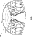
- FIG. 1 illustrates an example embodiment of an aircraft 100 that includes an overhead lighting system (e.g., lighting system 300) with a plurality of flexible light guides 200 configured as panels along an overhead portion 102 of the aircraft 100.
- the flexible light guides 200 are coupled to light sources 302 (e.g., LEDs, fluorescent lights, incandescent lights, etc.) disposed on the left side and/or right side of the overhead portion 102 of the aircraft 100.
- the light sources 302 may include one or more LED strips lining the left side and/or right side of the overhead portion 102 of the aircraft 100. While FIG.
- the lighting system 300 is not limited to aircraft installations and may be used in other vehicles (e.g., cars, trains, busses, boats, etc.), buildings, billboards, street signs, and so forth.
- vehicles e.g., cars, trains, busses, boats, etc.
- buildings e.g., billboards, street signs, and so forth.
- a flexible light guide 200 comprises a flexible substrate.
- the terms “flexible light guide” and “flexible substrate” are sometimes used interchangeably.
- the flexible light guide 200 includes the flexible substrate and may also include additional components (e.g., reflectors, coatings, diffusers, light steering features, etc.) that can be embedded within or coupled to the flexible substrate.
- the flexible light guide 200 has high transmission characteristics and may be flame-retardant as well.
- the flexible light guide 200 can be formed from silicon because it has the foregoing characteristics and is also flexible and casts well.
- the flexible light guide 200 is formed from an optically clear silicone (e.g., DOW CORNING SYLGARD 184, or the like).
- the flexible light guide 200 can also be formed other materials or compositions of materials that have similar transmission characteristics and physical properties to the transmission characteristics and physical properties of silicon.
- the flexible light guide 200 has at least two outer surfaces.
- the flexible light guide 200 in FIGS. 2A through 2C has a first outer surface 202 and a second outer surface 204 that is opposite the first outer surface 202.
- the flexible light guide 200 also has one or more edges surrounding the outer surfaces 202 and 204.
- the flexible light guide 200 can be rectangular with four edges (e.g., edges 206, 208, 212, and 214) surrounding the outer surfaces 202 and 204.
- the flexible light guide 200 may have any number of edges.
- the flexible light guide 200 can be another polygonal prism (e.g., triangular prism, pentagonal prism, etc.) with more or less edges, a circular or elliptical prism with only one edge surrounding the two outer surfaces 202 and 204, or a complex shape with a combination of straight and curved edges (e.g., such as the flexible light guide 200 shown in FIG. 11 ).
- another polygonal prism e.g., triangular prism, pentagonal prism, etc.
- a circular or elliptical prism with only one edge surrounding the two outer surfaces 202 and 204
- a complex shape with a combination of straight and curved edges e.g., such as the flexible light guide 200 shown in FIG. 11 ).
- At least one of the two outer surfaces 202 and 204 defines a light emitting area.
- the first surface 202 and/or the second surface 204 can be configured to emit at least a portion of light that is propagated through the flexible light guide 200 in between the two outer surfaces 202 and 204.
- the flexible light guide 200 includes a plurality of light extraction features 210 in between the outer surfaces 202 and 204.
- the light extraction features 210 include bubbles (e.g., fluid bubbles such as gas (e.g., air) or liquid bubbles) formed in between the outer surfaces 202 and 204.
- the light extraction features 210 are formed by a solid or semi-sold (e.g., gel) material embedded within the flexible light guide 200 that has different transmission characteristics than material (e.g., silicon) that makes up the flexible light guide 200.
- the light extraction features 210 are configured to cause a portion of the light propagating through the flexible light guide 200 to be released from a light emitting area defined by the first surface 202 and/or the second surface 204.
- the light extraction features 210 have a controlled distribution that affects a propagation of light in between the outer surfaces 202 and 204 and an emission of light from the light emitting area (i.e., from the first surface 202 and/or the second surface 204).
- FIGS. 3 through 8 show embodiments (300A-300F) of a lighting system 300 that includes the light guide 200 with its light extraction features 210 in various arrangements that allow for a lower percentage of the light propagating in between the outer surfaces 202 and 204 to emit from portions of the light emitting area near a light source 302 than other portions of the light emitting area that are further from the light source 302.
- regions of the light guide 200 that are further from the light source 302 will have less total light propagating in between the outer surfaces 202 and 204 than the regions that are near the light source 302 (e.g., due transmission losses and/or light emissions near the light source 302).
- the regions of the light guide 200 that are further from the light source 302 must emit a higher percentage of the remaining light if it is required to have a same or similar emission of photons as the regions that are closer to the light source 302.
- the flexible light guide 200 is configured to receive light from a light source 302 that is coupled to at least one edge of the flexible light guide 200.
- a lighting system 300 is shown to include a light source 302 coupled to an edge 206 of the flexible light guide 200.
- a reflector 216 may be disposed upon at least a portion of the other edges (e.g., edge 208, edge 212, and/or edge 214 not shown in Fig. 3 ) and/or other portions of edge 206 that are not coupled to the light source 302.
- the reflector 216 can be a reflective coating, reflective tape, and/or other reflective structure that is applied, adhered, or otherwise disposed upon edge 208, edge 212, edge 214, and/or other surfaces of the flexible light guide 200 that are not configured to receive or emit light.
- the first outer surface 202 may be fully or partially covered by a reflector 216, while the second outer surface 204 defines the light emitting area of the flexible light guide 200, or vice versa.
- the first outer surface 202 and the second outer surface 204 both define light emitting areas (e.g., where there is no reflector 216 covering either of the outer surfaces 202 or 204).
- the first outer surface 202 and/or the second outer surface 204 are partially covered.
- one or both of the outer surfaces 202 and 204 can be partially covered by a respective reflector 216 so that the outer surface 202/204 is configured to partially define a light emitting area.
- the light extraction features 210 are arranged according to a non-uniform distribution.
- a first region 218 of the flexible light guide 200 has less light extraction features 210 (or a lower density of light extraction features 210) than a second region 220 of the flexible light guide 200.
- the first region 218 is closer to the light source 302 than the second region 220, and the light guide 200 will therefore have more light propagating through the first region 218 than the second region 220 at any given time. Consequently, the first region 218 does not need to emit as high of a percentage of the light in order to produce the same light emissions as the second region 220.
- FIG. 7 shows an example embodiment of the light guide 200 with smaller light extraction features 210 in the first region 218 than in the second region 220.
- a light extraction feature 210A in the first region 218 that is close to the light source 302 may be smaller than a light extraction feature 210B in the second region 220 that is further from the light source 302.
- a combination of varying sizes of light extraction features 210 and number/density of light extraction features 210 in a region can be used to control the propagation of light between the outer surfaces 202 and 204 and/or the emission of light from the light emitting area defined by the first outer surface 202 and/or the second outer surface 204.
- the lighting system 300B may include a plurality of light sources 302.
- a first light source 302A is coupled to one edge 206 of the flexible light guide 200
- a second light source 302B is coupled to another edge 208 of the flexible light guide 200.
- a reflector 216 may be disposed upon at least a portion of the other edges (e.g., edge 212 and/or edge 214) and/or other portions of the light guide 200 that are not coupled to the light sources 302.
- the reflector 216 can be a reflective coating, reflective tape, and/or other reflective structure that is applied, adhered, or otherwise disposed upon edge 212, edge 214, and/or other surfaces of the flexible light guide 200 that are not configured to receive or emit light.
- the first outer surface 202 may be fully or partially covered by a reflector 216, while the second outer surface 204 defines the light emitting area of the flexible light guide 200, or vice versa.
- the first outer surface 202 and the second outer surface 204 both define light emitting areas (e.g., where there is no reflector 216 covering either of the outer surfaces 202 or 204).
- the first outer surface 202 and/or the second outer surface 204 are partially covered.
- one or both of the outer surfaces 202 and 204 can be partially covered by a respective reflector 216 so that the outer surface 202/204 is configured to partially define a light emitting area.
- the light extraction features 210 are also arranged according to a non-uniform distribution.
- edge regions 222 and 224 of the flexible light guide 200 have less light extraction features 210 (or a lower density of light extraction features 210) than an inner region 226 of the flexible light guide 200.
- the edge regions 222 and 224 are closer to the light sources 302 (e.g., the first light source 302A and the second light source 302B, respectively) than the inner region 226, and the light guide 200 will therefore have more light propagating through the edge regions 222 and 224 than the inner region 226 at any given time.
- the edge regions 222 and 224 do not need to emit as high of a percentage of the light if it is required to produce the same light emissions as the inner region 226.
- the volume or size of the light extraction features can be varied throughout different regions of the flexible light guide 200.
- FIG. 8 shows an example embodiment of the light guide 200 with smaller light extraction features 210 in the edge regions 222 and 224 than in the inner region 226.
- light extraction features 210C and 210D in the edge regions 222 and 224 may be smaller than a light extraction feature 210E in the inner region 226 that is further away from the light sources 302 than the edge regions 222 and 224.
- a combination of varying sizes of light extraction features 210 and number/density of light extraction features 210 in a region can be used to control the propagation of light between the outer surfaces 202 and 204 and/or the emission of light from the light emitting area defined by the first outer surface 202 and/or the second outer surface 204.
- FIGS. 5 and 6 illustrate embodiments 300C and 300D, respectively of the flexible light guide 200 having a non-uniform thickness.
- the edge 206 that is coupled to the light source 302 has a first thickness T1 and an inner portion (e.g., region 220) of the flexible light guide 200 has a second thickness T2 that is less than the first thickness T1.
- the flexible light guide 200 may be tapered so that the thickness of the flexible light guide 200 gradually decreases from the first thickness T1 to the second thickness T2 over the region 218 of the flexible light guide 200 that is proximate to the edge 206.
- the edge 208 that is opposite edge 206 can also have thickness T2.
- FIG. 1 the edge 208 that is opposite edge 206 can also have thickness T2.
- the light guide 200 has two edges 206 and 208 that are coupled to respective light sources 302A and 302B, respectively.
- the edges 206 and 208 may have greater thicknesses (e.g., thickness T1) than the thickness (e.g., thickness T2) of the inner region 226.
- the edge regions 222 and 224 can be tapered so that the thickness of the flexible light guide 200 gradually decreases from thickness T1 at the edges 206 and 208 to thickness T2 at the inner region 226.
- the flexible light guide 200 can be formed from less material. Having a slimmer form-factor can also provide for reduced space requirements for the lighting system 300 and enhanced aesthetic appearance.
- the flexible light guide 200 can be coupled to a light source 302 by a variety of different techniques.
- FIGS. 9 and 10 show example embodiments of the light source 302 coupled to the edge 206 of the flexible light guide 200.
- the light source 302 may include a support substrate 306 (e.g., a printed circuit board (PCB) or the like) with one or more light elements 308 (e.g., light emitting diodes (LEDs) or the like) disposed upon the support substrate 306.
- the light source 302 can be configured to direct light into the flexible light guide 200 through the edge 206.
- the light source 302 can be coupled directly to the edge 206 of the flexible light guide 200.
- the light source 302 includes an edge support structure 304 that is configured to receive at least a portion of the edge 206 within the edge support structure 304 and is further configured to hold the support substrate 306 so that the one or more light elements 308 are pointed at or into the edge 206.
- FIG. 10 shows another example embodiment where the light source 302 is configured to direct light into the flexible light guide 200 through a portion of the outer surface 204 that is adjacent to the edge 206.
- the edge 206 may be covered or coated by a reflector 216 so that the light that is directed into the flexible light guide 200 through the portion of the outer surface 204 can reflect off the edge 206 and propagate towards inner regions of the flexible light guide 200.
- the light source 302 itself can include a light guide structure (e.g., fiber optic, acrylic light guide, etc.).
- the light source 302 can include another flexible light guide 200.
- two or more flexible light guides 200 can be daisy chained by placing the flexible light guides 200 edge-to-edge without reflectors 216 covering the interfacing edges. In this manner, two or more flexible light guides 200 can be operable as one larger light guide structure.
- the light source 302 can be integrated within the flexible light guide 200.
- at least a portion of the light source 302 can be embedded with the flexible light guide 200.
- the light source 302 may be embedded within the flexible light guide 200 during an injection molding process or by removing a portion of the flexible light guide 200 and inserting at least a portion of the light source 302 in place of the removed portion.
- FIG. 11 shows an embodiment of a lighting system 300G where the flexible light guide 200 is shaped like a person (e.g., for a washroom sign or the like).
- the flexible light guide 200 in FIG. 11 has an edge 228 coupled to the light source 302 while its other edges or edge regions (e.g., edge 230 and so forth) are covered by reflector 216.
- the outer surfaces (e.g., surfaces 202 and 204) of the flexible light guide 200 are both configured to emit light (e.g., no reflector 216 is disposed on either of the surfaces 202 or 204).
- the flexible light guide 200 may be suspended longitudinally (e.g., as shown in FIG. 11 ) so both of the outer surfaces 202 and 204 of the flexible light guide 200 by individuals looking from the front or the back.
- This arrangement can be useful for signage (e.g., washroom signs, exit signs, etc.), emergency lighting applications, decorative lighting, and so forth.
- signage e.g., washroom signs, exit signs, etc.
- emergency lighting applications e.g., decorative lighting, and so forth.
- only one of the outer surfaces e.g., surface 204
- the other outer surface e.g., surface 202
- a reflector 216 so that most of the light is emitted by the visible outer surface (e.g., surface 204).
- the flexible light guide 200 can include one or more light steering features to control the propagation of light in between the two outer surfaces 202 and 204.
- a light steering feature can be configured to redirect a portion of the light propagating in between the two outer surfaces 202 and 204 when the light at least partially reflects off of the light steering feature.
- the one or more light steering features include reflectors 216 (e.g., reflective coating, reflective elements, etc.) disposed upon one or more outer edges (e.g., edges 208, 212, and/or 214) of the flexible light guide 200.
- the one or more light steering features can include reflective elements 232 embedded within the flexible light guide 200 (e.g., at least partially between the two outer surfaces 202 and 204).
- reflective elements 232 can include, but are not limited to, reflective/refractive lenses, prisms, mirrors, or the like.
- the reflective elements 232 can be formed from one or more materials with different refractive indices than the material (e.g., silicon) of the flexible light guide 200.
- the reflective elements 232 may be embedded within the flexible light guide 200 during an injection molding process or by removing a portion of the flexible light guide 200 and inserting a reflective element 232 in place of the removed portion.
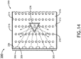
- the one or more light steering features can additionally or alternatively include a reflector 236 (e.g., the same as or similar to reflector 216) that is disposed upon at least a portion of an inner edge of a cutout portion 234 of the flexible light guide 200.
- a portion of the flexible light guide 200 can be removed, leaving a cutout portion 234.
- the reflector 236 can then be coated, adhered, or otherwise disposed upon the edges surrounding the cutout portion 234.
- one or more light steering features are configured to direct light towards one or more regions of the flexible light guide 200 (e.g., towards the center, away from the center and towards one or more sides, etc.).
- the light may be directed away from the center and towards the side portions of the flexible light guide 200 if one light source 302 is used to illuminate two signs, where a first sign is formed by a first side portion of the flexible light guide 200 and a second sign is formed by a second side portion of the flexible light guide 200.
- the lighting system 300 includes a light fixture system that is configured to support the flexible light guide 200 against a surface for installation (e.g., against the overhead portion 102 of the aircraft 100 in FIG. 1 ).
- the light fixture system can be configured to support the flexible light guide 200 against a curved surface, planar surface, angled surface, or any combination thereof.
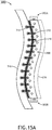
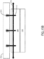
- FIGS. 15A through 15C show example embodiments of the lighting system 300 with light fixture system components.
- the light fixture system includes at least one longitudinal support member 310 with first projections 314 and second projections 312 extending outwardly from the longitudinal support member 310 in opposing directions.
- the first projections 314 are configured to couple the longitudinal support member 310 with a support surface 316.
- the first projections 314 may include snap fit connectors (e.g., connector balls or other male/female connectors) that attach the first projections 314 to cooperative snap fit connectors (e.g., connector sockets or other female/male connectors) formed or disposed on/in the support surface 316.
- the second projections 312 at least partially extend through an outer surface (e.g., outer surface 202) of the flexible light guide 200 to couple the flexible light guide 200 to the support surface 316.
- the second projections 312 are embedded within the flexible light guide 200 during an injection molding process or by removing portions of the flexible light guide 200 and inserting the second projections 312 in place of the removed portions.
- the second projections 312 may be forced into the flexible light guide 200 (e.g., like nails or spikes).
- the lighting system 300 may include a plurality of longitudinal support structures 310 for affixing the flexible light guide 200 to the support surface 316.
- the lighting system 300 also includes a plurality of support surfaces 316.
- the flexible light guide 200 or a plurality of flexible light guides 200 can be fixed along a structure lined with a plurality of support surfaces 316 configured to support the flexible light guide 200 or plurality of flexible light guides 200.
- a diffuser 238 may be disposed upon the flexible light guide 200.
- the diffuser 238 can be formed from a layer (e.g., diffused material layer, such as diffused silicon or the like) on the flexible light guide 200.
- the diffuser 238 is a coating disposed upon the outer surface (e.g., outer surface 202 or 204) that defines the light emitting area.
- the diffuser 238 is a textured or patterned portion of the outer surface (e.g., outer surface 202 or 204) that defines the light emitting area.
- the diffuser 238 is a sheet (e.g., plastic sheet or the like) that is disposed adjacent to the outer surface (e.g., outer surface 202 or 204) that defines the light emitting area.
- the diffuser 238 can be configured to diffuse the light emitted from the light emitting area to improve uniformity of light emission from the flexible light guide 200.
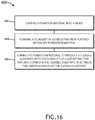
- FIG. 16 illustrates an example implementation of a method 400 of manufacturing a flexible light guide, such as the flexible light guide 200 shown in FIGS. 1 through 15C .
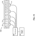
- FIGS. 17 through 19 illustrate example embodiments of a system 500 that can be used to implement the method 400.
- other tools can also be employed to implement the step, operations, or process blocks of the method 400.
- operations of disclosed processes e.g., method 400
- the method 400 includes casting formation material (e.g., silicon) into a mold or tool (block 402).
- the system 500 includes a mold 504 configured to receive formation material 502 within a cavity defined by the mold 504.
- the formation material 502 is flowed or injected into the mold 504.
- the formation material 502 may be injected into the mold 504 at a selected pressure.
- the method 400 further includes forming a plurality of light extraction features within the formation material (block 404).
- the system 500 is configured to produce a controlled distribution of light extraction features 510 (e.g., bubbles) within the formation material 502 after the formation material 502 is disposed within the mold 504.
- the light extraction features 510 may be produced by injecting air through pores 506 in the mold 504 after casting the formation material 502 into the mold 504.
- air generally refers to any gas or mixture of gases.
- a gas source 508 e.g., an air compressor, a pressurized canister, or the like
- the gas source 508 is fluidically coupled to one or more control valves 512 that manage the flow rate of air through the pores 506.
- the pores 506 may be positioned according to the controlled distribution.
- a first region of the resulting flexible substrate e.g., flexible light guide 200
- a second region of the flexible substrate that is configured to be further from the light source (e.g., light source 302) than the first region.
- the gas source 508 and/or control valves 512 are configured to inject more air through pores 506 in one area than in another area.
- a first region of the resulting flexible substrate (e.g., flexible light guide 200) may have smaller light extraction 510 features than a second region of the flexible substrate that is configured to be further from the light source (e.g., light source 302) than the first region.
- the light source e.g., light source 302
- the distribution of the light extraction features 510 throughout the formation material 502 is controlled by applying vibrations to the formation material 502 to selectively release bubbles from regions of the formation material 502 after the formation material 502 is cast into the mold 504.
- a plurality of transducers 514 e.g., piezo electric transducers or the like
- the transducers 514 have a non-uniform distribution.
- the transducers 514 are uniformly distributed but controlled according to a non-uniform actuation scheme.
- the transducers 514 may be coupled to a controller 516 (e.g., micro-controller, processor, programmable logic device, etc.) that is configured to control energy furnished to respective ones of the transducers 514 from an energy source 518 (e.g., electrical outlet, battery, generator, or the like).
- the controller 516 may be configured to execute an actuation scheme based on program instructions stored in memory of the controller 516.
- the system 500 may further include a camera system that monitors the quantity and/or distribution of the light extraction features 510 (e.g., bubbles) and updates the actuation scheme based on detected changes in the quantity and/or distribution of the light extraction features 510.
- the formation material 502 is cured to produce a flexible substrate (e.g., flexible light guide 200).
- the formation material 502 can be cured by allowing the formation material 502 to dry.
- the formation material 502 is cured by heating or cooling the formation material 502 to selected temperature.
- the formation material 502 is cured by applying electromagnetic radiation (e.g., UV light or another wavelength of illumination appropriate for curing the formation material 502).
- the formation material 502 may be cured by applying a curing agent to the formation material 502.
- embodiments of the methods according to the inventive concepts disclosed herein may include one or more of the steps described herein. Further, such steps may be carried out in any desired order and two or more of the steps may be carried out simultaneously with one another. Two or more of the steps disclosed herein may be combined in a single step, and in some embodiments, one or more of the steps may be carried out as two or more sub-steps. Further, other steps or sub-steps may be carried in addition to, or as substitutes to one or more of the steps disclosed herein.
- inventive concepts disclosed herein are well adapted to carry out the objects and to attain the advantages mentioned herein as well as those inherent in the inventive concepts disclosed herein. While presently preferred embodiments of the inventive concepts disclosed herein have been described for purposes of this disclosure, it will be understood that numerous changes may be made which will readily suggest themselves to those skilled in the art and which are accomplished within the broad scope and coverage of the inventive concepts claimed herein.
Landscapes
- Physics & Mathematics (AREA)
- General Physics & Mathematics (AREA)
- Optics & Photonics (AREA)
- Engineering & Computer Science (AREA)
- Manufacturing & Machinery (AREA)
- Mechanical Engineering (AREA)
- Aviation & Aerospace Engineering (AREA)
- Health & Medical Sciences (AREA)
- Ophthalmology & Optometry (AREA)
- Planar Illumination Modules (AREA)
- Non-Portable Lighting Devices Or Systems Thereof (AREA)
Abstract
Description
- Edge lighting may be desirable in an aircraft because, in an edge-lit system, a light source and its associated hardware can be placed in a convenient (out of the way) location while a light guide transmits light from the light source to a light emitting surface. On the other hand, backlit systems require the light source to be positioned directly behind the light emitting surface. This makes installation of backlit systems more complicated. For example, backlit systems may require additional wiring in order to have the light source positioned behind the light emitting surface; or in some cases, it may be impossible to install the light emitting surface at a desired location due to wiring and/or spatial limitations.
- Acrylics are often used for edge lighting. However, most acrylics do not meet aviation industry standards because they are too flammable to be used on an aircraft. The next viable option would be polycarbonate, which is inherently flame-retardant. However, polycarbonate has a high transmission loss when light travels through it. This material characteristic of polycarbonate renders it a non-ideal material for a light guide. There is a need for new edge lighting solutions, particularly ones that meet aviation industry standards.
- In one aspect, embodiments of the inventive concepts disclosed herein are directed to a flexible light guide. The flexible light guide comprises a flexible substrate having two outer surfaces with at least one of the two outer surfaces defining a light emitting area. At least one edge of the flexible substrate is configured to receive light from a light source coupled to the edge. The flexible light guide also includes a plurality of light extraction features formed within the flexible substrate in between the two outer surfaces. The light extraction features is arranged according to a controlled distribution that affects a propagation of light in between the two outer surfaces and an emission of light from the light emitting area.
- In a further aspect, embodiments of the inventive concepts disclosed herein are directed to a method of manufacturing a flexible light guide. The method includes casting formation material into a mold and forming a plurality of light extraction features within the formation material. The formation material is then cured to produce a flexible substrate with the plurality of light extraction features embedded within the flexible substrate (e.g., embedded in between two outer surfaces of the flexible substrate). The light extraction features formed within the formation material are arranged according to a controlled distribution that affects a propagation of light in between the two outer surfaces the resulting flexible substrate and an emission of light from a light emitting area defined by at least one of the two outer surfaces.
- In a further aspect, embodiments of the inventive concepts disclosed herein are directed to a lighting system. The lighting system includes a light source, a light fixture, and a light guide coupled to the light source and the light fixture. The light fixture includes at least one longitudinal support member with first projections and second projections. The first projections are configured to couple the longitudinal support member with a curved support surface. The light guide is configured to extend along the curved support surface. The light guide comprises a flexible substrate having two outer surfaces. A first outer surface defines a light emitting area, and a second outer surface is coupled to the second projections of the light fixture. The second projections at least partially extend through the second outer surface of the flexible substrate to couple the flexible substrate to the curved support surface. At least one edge of the flexible substrate is configured to receive light from a light source coupled to the edge. The light guide also includes a plurality of light extraction features formed within the flexible substrate in between the two outer surfaces. The light extraction features is arranged according to a controlled distribution that affects a propagation of light in between the two outer surfaces and an emission of light from the light emitting area.
- This summary is provided solely as an introduction to subject matter that is fully described in the description and drawings. The summary should not be considered to describe essential features nor be used to determine the scope of the claims. Moreover, it is to be understood that both the foregoing summary and the following description are example and explanatory only and are not necessarily restrictive of the subject matter claimed.
- Implementations of the inventive concepts disclosed herein may be better understood when consideration is given to the following detailed description thereof. Such description makes reference to the included drawings, which are not necessarily to scale, and in which some features may be exaggerated and some features may be omitted or may be represented schematically in the interest of clarity. Like reference numerals in the drawings may represent and refer to the same or similar element, feature, or function. In the drawings:
-
FIG. 1 is an illustration of an aircraft environment in which a lighting system can be implemented in accordance with the instant invention, where the lighting system includes at least one flexible light guide; -
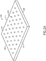
FIG. 2A is a perspective top view of a flexible light guide in accordance with the instant invention; -
FIG. 2B is a perspective bottom view of a flexible light guide ofFig. 2A ; -
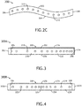
FIG. 2C is a cross-sectional side view of the flexible light guide ofFig. 2A and2B ; -
FIG. 3 is a cross-sectional side view of a lighting system that includes a flexible light guide in accordance with the instant invention; -
FIG. 4 is a cross-sectional side view of another lighting system that includes a flexible light guide in accordance with the instant invention; -
FIG. 5 is a cross-sectional side view of yet another lighting system that includes a flexible light guide in accordance with the instant invention; -
FIG. 6 is a cross-sectional side view of still another lighting system that includes a flexible light guide in accordance with the instant invention; -
FIG. 7 is a cross-sectional side view of another lighting system that includes a flexible light guide in accordance with the instant invention; -
FIG. 8 is a cross-sectional side view of yet another lighting system that includes a flexible light guide in accordance with the instant invention; -
FIG. 9 is a partial cross-sectional side view illustrating a connection between a light source and a flexible light guide in accordance with the instant invention; -
FIG. 10 is a partial cross-sectional side view illustrating a connection between the light source and the flexible light guide ofFig. 9 ; -
FIG. 11 is a top view of a lighting system that includes a flexible light guide in accordance with the instant invention; -
FIG. 12 is a top view of another lighting system that includes a flexible light guide in accordance with the instant invention; -
FIG. 13 is a top view of a lighting system that includes a flexible light guide with one or more embedded reflective elements for steering light in accordance with the instant invention; -
FIG. 14 is a partial top view of a lighting system that includes a flexible light guide with one or more cutout portions for steering light in accordance with the instant invention; -
FIG. 15A is a cross-sectional side view of a lighting system that includes a flexible light guide in accordance with the instant invention, where the lighting system includes one or more light fixture components at least partially embedded within the flexible light guide; -
FIG. 15B is a cross-sectional side view of a lighting system that includes a flexible light guide in accordance with the instant invention, where the lighting system includes one or more light fixture components at least partially embedded within the flexible light guide; -
FIG. 15C is a top view of a lighting system that includes a flexible light guide in accordance with the instant invention, where the lighting system includes one or more light fixture components at least partially embedded within the flexible light guide; -
FIG. 16 is a flow diagram illustrating an example implementation of a method for manufacturing a flexible light guide in accordance with the instant invention; -
FIG. 17 is a cross-sectional side view of a system for manufacturing a flexible light guide in accordance with the instant invention; -
FIG. 18 is a cross-sectional side view of another system for manufacturing a flexible light guide in accordance with the instant invention and -
FIG. 19 is a cross-sectional side view of yet another system for manufacturing a flexible light guide in accordance with the instant invention. - Before explaining at least one embodiment of the inventive concepts disclosed herein in detail, it is to be understood that the inventive concepts are limited by the appendant independent claims. The invention is not limited further in their application to the details of construction and the arrangement of the components or steps or methodologies set forth in the following description or illustrated in the drawings. For example, in the following detailed description of embodiments of the instant inventive concepts, numerous specific details are set forth in order to provide a more thorough understanding of the inventive concepts. However, it will be apparent to one of ordinary skill in the art having the benefit of the instant disclosure that the inventive concepts disclosed herein may be practiced without these specific details. In other instances, well-known features may not be described in detail to avoid unnecessarily complicating the instant disclosure. The inventive concepts disclosed herein are capable of other embodiments or of being practiced or carried out in various ways. Also, it is to be understood that the phraseology and terminology employed herein is for the purpose of description and should not be regarded as limiting.
- As used herein a letter following a reference numeral is intended to reference an embodiment of the feature or element that may be similar, but not necessarily identical, to a previously described element or feature bearing the same reference numeral (e.g., 1, 1a, 1b). Such shorthand notations are used for purposes of convenience only, and should not be construed to limit the inventive concepts disclosed herein in any way unless expressly stated to the contrary. Also similar but not identical features may be referred to with the same reference numeral.
- Further, unless expressly stated to the contrary, "or" refers to an inclusive or and not to an exclusive or. For example, a condition A or B is satisfied by anyone of the following: A is true (or present) and B is false (or not present), A is false (or not present) and B is true (or present), and both A and B are true (or present).
- In addition, use of the "a" or "an" are employed to describe elements and components of embodiments of the instant inventive concepts. This is done merely for convenience and to give a general sense of the inventive concepts, and "a' and "an" are intended to include one or at least one and the singular also includes the plural unless it is obvious that it is meant otherwise.
- Finally, as used herein any reference to "one embodiment," or "some embodiments" means that a particular element, feature, structure, or characteristic described in connection with the embodiment is included in at least one embodiment of the inventive concepts disclosed herein. The appearances of the phrase "in some embodiments" in various places in the specification are not necessarily all referring to the same embodiment, and embodiments of the inventive concepts disclosed may include one or more of the features expressly described or inherently present herein, or any combination of sub-combination of two or more such features, along with any other features which may not necessarily be expressly described or inherently present in the instant disclosure.
- Broadly, embodiments of the inventive concepts disclosed herein are directed to flexible light guides and techniques for manufacturing the same. Embodiments of the inventive concepts herein are also directed to lighting systems that include flexible light guides (e.g., for edge lighting solutions). The light guide structures and systems disclosed herein may allow for highly controlled color accuracy and dimming capabilities as well as consistency from lighting panel to panel. The flexibility of the disclosed light guide structures are well-suited for aircraft interiors due to the complex curvatures that currently exist within aircrafts. Furthermore, the light guide structures can be formed from materials that meet aviation industry standards (e.g., fire, smoke, and toxicity requirements). It is also contemplated that the light guide structures and systems disclosed herein can be implemented in other environments (e.g., lighting systems for other types of vehicles, indoor/outdoor lighting systems, etc.).
-
FIG. 1 illustrates an example embodiment of anaircraft 100 that includes an overhead lighting system (e.g., lighting system 300) with a plurality of flexible light guides 200 configured as panels along anoverhead portion 102 of theaircraft 100. The flexible light guides 200 are coupled to light sources 302 (e.g., LEDs, fluorescent lights, incandescent lights, etc.) disposed on the left side and/or right side of theoverhead portion 102 of theaircraft 100. For example, thelight sources 302 may include one or more LED strips lining the left side and/or right side of theoverhead portion 102 of theaircraft 100. WhileFIG. 1 illustrates an example embodiment of thelighting system 300 in anaircraft 100, thelighting system 300 is not limited to aircraft installations and may be used in other vehicles (e.g., cars, trains, busses, boats, etc.), buildings, billboards, street signs, and so forth. - Referring now to
FIGS. 2A through 2C , a flexiblelight guide 200 comprises a flexible substrate. As used herein, the terms "flexible light guide" and "flexible substrate" are sometimes used interchangeably. It is to be understood that the flexiblelight guide 200 includes the flexible substrate and may also include additional components (e.g., reflectors, coatings, diffusers, light steering features, etc.) that can be embedded within or coupled to the flexible substrate. The flexiblelight guide 200 has high transmission characteristics and may be flame-retardant as well. In embodiments, the flexiblelight guide 200 can be formed from silicon because it has the foregoing characteristics and is also flexible and casts well. In some embodiments, the flexiblelight guide 200 is formed from an optically clear silicone (e.g., DOW CORNING SYLGARD 184, or the like). The flexiblelight guide 200 can also be formed other materials or compositions of materials that have similar transmission characteristics and physical properties to the transmission characteristics and physical properties of silicon. - The flexible
light guide 200 has at least two outer surfaces. For example, the flexiblelight guide 200 inFIGS. 2A through 2C has a firstouter surface 202 and a secondouter surface 204 that is opposite the firstouter surface 202. The flexiblelight guide 200 also has one or more edges surrounding theouter surfaces light guide 200 can be rectangular with four edges (e.g., edges 206, 208, 212, and 214) surrounding theouter surfaces light guide 200 may have any number of edges. For example, in other embodiments, the flexiblelight guide 200 can be another polygonal prism (e.g., triangular prism, pentagonal prism, etc.) with more or less edges, a circular or elliptical prism with only one edge surrounding the twoouter surfaces light guide 200 shown inFIG. 11 ). - At least one of the two
outer surfaces first surface 202 and/or thesecond surface 204 can be configured to emit at least a portion of light that is propagated through the flexiblelight guide 200 in between the twoouter surfaces light guide 200 includes a plurality of light extraction features 210 in between theouter surfaces outer surfaces light guide 200 that has different transmission characteristics than material (e.g., silicon) that makes up the flexiblelight guide 200. The light extraction features 210 are configured to cause a portion of the light propagating through the flexiblelight guide 200 to be released from a light emitting area defined by thefirst surface 202 and/or thesecond surface 204. - The light extraction features 210 have a controlled distribution that affects a propagation of light in between the
outer surfaces first surface 202 and/or the second surface 204). For example,FIGS. 3 through 8 show embodiments (300A-300F) of alighting system 300 that includes thelight guide 200 with its light extraction features 210 in various arrangements that allow for a lower percentage of the light propagating in between theouter surfaces light source 302 than other portions of the light emitting area that are further from thelight source 302. As further described herein, the arrangements of light extraction features 210 illustrated inFIGS. 3 through 8 can achieve uniformity (or near uniformity) of light emissions across the light emitting area because regions of thelight guide 200 that are further from thelight source 302 will have less total light propagating in between theouter surfaces light guide 200 that are further from thelight source 302 must emit a higher percentage of the remaining light if it is required to have a same or similar emission of photons as the regions that are closer to thelight source 302. - The flexible
light guide 200 is configured to receive light from alight source 302 that is coupled to at least one edge of the flexiblelight guide 200. In the example embodiment shown inFIG. 3 , alighting system 300 is shown to include alight source 302 coupled to anedge 206 of the flexiblelight guide 200. To maintain internal reflection of light within thelight guide 200, areflector 216 may be disposed upon at least a portion of the other edges (e.g.,edge 208,edge 212, and/or edge 214 not shown inFig. 3 ) and/or other portions ofedge 206 that are not coupled to thelight source 302. For example, thereflector 216 can be a reflective coating, reflective tape, and/or other reflective structure that is applied, adhered, or otherwise disposed uponedge 208,edge 212,edge 214, and/or other surfaces of the flexiblelight guide 200 that are not configured to receive or emit light. In embodiments, the firstouter surface 202 may be fully or partially covered by areflector 216, while the secondouter surface 204 defines the light emitting area of the flexiblelight guide 200, or vice versa. In some embodiments, the firstouter surface 202 and the secondouter surface 204 both define light emitting areas (e.g., where there is noreflector 216 covering either of theouter surfaces 202 or 204). In other embodiments, the firstouter surface 202 and/or the secondouter surface 204 are partially covered. For example, one or both of theouter surfaces respective reflector 216 so that theouter surface 202/204 is configured to partially define a light emitting area. - In the embodiment shown in
FIG. 3 , the light extraction features 210 are arranged according to a non-uniform distribution. For example, afirst region 218 of the flexiblelight guide 200 has less light extraction features 210 (or a lower density of light extraction features 210) than asecond region 220 of the flexiblelight guide 200. Thefirst region 218 is closer to thelight source 302 than thesecond region 220, and thelight guide 200 will therefore have more light propagating through thefirst region 218 than thesecond region 220 at any given time. Consequently, thefirst region 218 does not need to emit as high of a percentage of the light in order to produce the same light emissions as thesecond region 220. In some embodiments, instead of varying the number or density of light extraction features in regions of the flexiblelight guide 200, the volume or size of the light extraction features can be varied throughout different regions of the flexiblelight guide 200.FIG. 7 shows an example embodiment of thelight guide 200 with smaller light extraction features 210 in thefirst region 218 than in thesecond region 220. For example, alight extraction feature 210A in thefirst region 218 that is close to thelight source 302 may be smaller than alight extraction feature 210B in thesecond region 220 that is further from thelight source 302. In other embodiments, a combination of varying sizes of light extraction features 210 and number/density of light extraction features 210 in a region can be used to control the propagation of light between theouter surfaces outer surface 202 and/or the secondouter surface 204. - As shown in
FIG. 4 , thelighting system 300B may include a plurality oflight sources 302. For example, a firstlight source 302A is coupled to oneedge 206 of the flexiblelight guide 200, and a secondlight source 302B is coupled to anotheredge 208 of the flexiblelight guide 200. To maintain internal reflection of light within thelight guide 200, areflector 216 may be disposed upon at least a portion of the other edges (e.g.,edge 212 and/or edge 214) and/or other portions of thelight guide 200 that are not coupled to thelight sources 302. For example, thereflector 216 can be a reflective coating, reflective tape, and/or other reflective structure that is applied, adhered, or otherwise disposed uponedge 212,edge 214, and/or other surfaces of the flexiblelight guide 200 that are not configured to receive or emit light. In embodiments, the firstouter surface 202 may be fully or partially covered by areflector 216, while the secondouter surface 204 defines the light emitting area of the flexiblelight guide 200, or vice versa. In some embodiments, the firstouter surface 202 and the secondouter surface 204 both define light emitting areas (e.g., where there is noreflector 216 covering either of theouter surfaces 202 or 204). In other embodiments, the firstouter surface 202 and/or the secondouter surface 204 are partially covered. For example, one or both of theouter surfaces respective reflector 216 so that theouter surface 202/204 is configured to partially define a light emitting area. - In the embodiment shown in
FIG. 4 , the light extraction features 210 are also arranged according to a non-uniform distribution. For example,edge regions light guide 200 have less light extraction features 210 (or a lower density of light extraction features 210) than aninner region 226 of the flexiblelight guide 200. Theedge regions light source 302A and the secondlight source 302B, respectively) than theinner region 226, and thelight guide 200 will therefore have more light propagating through theedge regions inner region 226 at any given time. Consequently, theedge regions inner region 226. In some embodiments, instead of varying the number or density of light extraction features in regions of the flexiblelight guide 200, the volume or size of the light extraction features can be varied throughout different regions of the flexiblelight guide 200.FIG. 8 shows an example embodiment of thelight guide 200 with smaller light extraction features 210 in theedge regions inner region 226. For example, light extraction features 210C and 210D in theedge regions light extraction feature 210E in theinner region 226 that is further away from thelight sources 302 than theedge regions outer surfaces outer surface 202 and/or the secondouter surface 204. -
FIGS. 5 and 6 illustrateembodiments light guide 200 having a non-uniform thickness. For example, in an embodiment shown inFIG. 5 , theedge 206 that is coupled to thelight source 302 has a first thickness T1 and an inner portion (e.g., region 220) of the flexiblelight guide 200 has a second thickness T2 that is less than the first thickness T1. The flexiblelight guide 200 may be tapered so that the thickness of the flexiblelight guide 200 gradually decreases from the first thickness T1 to the second thickness T2 over theregion 218 of the flexiblelight guide 200 that is proximate to theedge 206. In the embodiment shown inFIG. 5 , theedge 208 that isopposite edge 206 can also have thickness T2.FIG. 6 illustrates another embodiment where thelight guide 200 has twoedges light sources edges inner region 226. Theedge regions light guide 200 gradually decreases from thickness T1 at theedges inner region 226. When the flexiblelight guide 200 is tapered in the manner illustrated inFIGS. 5 and 6 , or the like, the flexiblelight guide 200 can be formed from less material. Having a slimmer form-factor can also provide for reduced space requirements for thelighting system 300 and enhanced aesthetic appearance. - The flexible
light guide 200 can be coupled to alight source 302 by a variety of different techniques.FIGS. 9 and 10 show example embodiments of thelight source 302 coupled to theedge 206 of the flexiblelight guide 200. Thelight source 302 may include a support substrate 306 (e.g., a printed circuit board (PCB) or the like) with one or more light elements 308 (e.g., light emitting diodes (LEDs) or the like) disposed upon thesupport substrate 306. As shown inFIG. 9 , thelight source 302 can be configured to direct light into the flexiblelight guide 200 through theedge 206. For example, thelight source 302 can be coupled directly to theedge 206 of the flexiblelight guide 200. In embodiments, thelight source 302 includes anedge support structure 304 that is configured to receive at least a portion of theedge 206 within theedge support structure 304 and is further configured to hold thesupport substrate 306 so that the one or morelight elements 308 are pointed at or into theedge 206.FIG. 10 shows another example embodiment where thelight source 302 is configured to direct light into the flexiblelight guide 200 through a portion of theouter surface 204 that is adjacent to theedge 206. In such embodiments, theedge 206 may be covered or coated by areflector 216 so that the light that is directed into the flexiblelight guide 200 through the portion of theouter surface 204 can reflect off theedge 206 and propagate towards inner regions of the flexiblelight guide 200. - It is contemplated that various techniques may be employed to direct light into the flexible
light guide 200 at one or more edges (e.g., edges 206, 208, 212, and/or 214) or portions thereof. For example, in other embodiments, thelight source 302 itself can include a light guide structure (e.g., fiber optic, acrylic light guide, etc.). In some embodiments, thelight source 302 can include another flexiblelight guide 200. For example, two or more flexible light guides 200 can be daisy chained by placing the flexible light guides 200 edge-to-edge withoutreflectors 216 covering the interfacing edges. In this manner, two or more flexible light guides 200 can be operable as one larger light guide structure. - In some embodiments, the
light source 302 can be integrated within the flexiblelight guide 200. For example, at least a portion of thelight source 302 can be embedded with the flexiblelight guide 200. Thelight source 302 may be embedded within the flexiblelight guide 200 during an injection molding process or by removing a portion of the flexiblelight guide 200 and inserting at least a portion of thelight source 302 in place of the removed portion. - As previously discussed, the flexible
light guide 200 can be formed in virtually any shape depending on the lighting application. For example,FIG. 11 shows an embodiment of alighting system 300G where the flexiblelight guide 200 is shaped like a person (e.g., for a washroom sign or the like). The flexiblelight guide 200 inFIG. 11 has anedge 228 coupled to thelight source 302 while its other edges or edge regions (e.g.,edge 230 and so forth) are covered byreflector 216. In some embodiments, the outer surfaces (e.g., surfaces 202 and 204) of the flexiblelight guide 200 are both configured to emit light (e.g., noreflector 216 is disposed on either of thesurfaces 202 or 204). For example, the flexiblelight guide 200 may be suspended longitudinally (e.g., as shown inFIG. 11 ) so both of theouter surfaces light guide 200 by individuals looking from the front or the back. This arrangement can be useful for signage (e.g., washroom signs, exit signs, etc.), emergency lighting applications, decorative lighting, and so forth. In other applications, such as the aircraft lighting application illustrated inFIG. 1 , only one of the outer surfaces (e.g., surface 204) is visible when thelighting system 300 is installed and therefore it is more efficient to cover the other outer surface (e.g., surface 202) with areflector 216 so that most of the light is emitted by the visible outer surface (e.g., surface 204). - Referring now to
FIGS. 12 through 14 , the flexiblelight guide 200 can include one or more light steering features to control the propagation of light in between the twoouter surfaces outer surfaces FIG. 12 , the one or more light steering features include reflectors 216 (e.g., reflective coating, reflective elements, etc.) disposed upon one or more outer edges (e.g., edges 208, 212, and/or 214) of the flexiblelight guide 200. - In some embodiments, for example as shown in
FIG. 13 , the one or more light steering features can includereflective elements 232 embedded within the flexible light guide 200 (e.g., at least partially between the twoouter surfaces 202 and 204). Examples ofreflective elements 232 can include, but are not limited to, reflective/refractive lenses, prisms, mirrors, or the like. Thereflective elements 232 can be formed from one or more materials with different refractive indices than the material (e.g., silicon) of the flexiblelight guide 200. Thereflective elements 232 may be embedded within the flexiblelight guide 200 during an injection molding process or by removing a portion of the flexiblelight guide 200 and inserting areflective element 232 in place of the removed portion. - As shown in
FIG. 14 , the one or more light steering features can additionally or alternatively include a reflector 236 (e.g., the same as or similar to reflector 216) that is disposed upon at least a portion of an inner edge of acutout portion 234 of the flexiblelight guide 200. For example, a portion of the flexiblelight guide 200 can be removed, leaving acutout portion 234. Thereflector 236 can then be coated, adhered, or otherwise disposed upon the edges surrounding thecutout portion 234. - In some embodiments, one or more light steering features are configured to direct light towards one or more regions of the flexible light guide 200 (e.g., towards the center, away from the center and towards one or more sides, etc.). For example, the light may be directed away from the center and towards the side portions of the flexible
light guide 200 if onelight source 302 is used to illuminate two signs, where a first sign is formed by a first side portion of the flexiblelight guide 200 and a second sign is formed by a second side portion of the flexiblelight guide 200. - In embodiments, the
lighting system 300 includes a light fixture system that is configured to support the flexiblelight guide 200 against a surface for installation (e.g., against theoverhead portion 102 of theaircraft 100 inFIG. 1 ). For example, the light fixture system can be configured to support the flexiblelight guide 200 against a curved surface, planar surface, angled surface, or any combination thereof.FIGS. 15A through 15C show example embodiments of thelighting system 300 with light fixture system components. The light fixture system includes at least onelongitudinal support member 310 withfirst projections 314 andsecond projections 312 extending outwardly from thelongitudinal support member 310 in opposing directions. Thefirst projections 314 are configured to couple thelongitudinal support member 310 with asupport surface 316. For example, thefirst projections 314 may include snap fit connectors (e.g., connector balls or other male/female connectors) that attach thefirst projections 314 to cooperative snap fit connectors (e.g., connector sockets or other female/male connectors) formed or disposed on/in thesupport surface 316. Thesecond projections 312 at least partially extend through an outer surface (e.g., outer surface 202) of the flexiblelight guide 200 to couple the flexiblelight guide 200 to thesupport surface 316. In some embodiments, thesecond projections 312 are embedded within the flexiblelight guide 200 during an injection molding process or by removing portions of the flexiblelight guide 200 and inserting thesecond projections 312 in place of the removed portions. In other embodiments, thesecond projections 312 may be forced into the flexible light guide 200 (e.g., like nails or spikes). - As shown in
FIG. 15C , thelighting system 300 may include a plurality oflongitudinal support structures 310 for affixing the flexiblelight guide 200 to thesupport surface 316. In some embodiments, thelighting system 300 also includes a plurality of support surfaces 316. For example, the flexiblelight guide 200 or a plurality of flexible light guides 200 can be fixed along a structure lined with a plurality of support surfaces 316 configured to support the flexiblelight guide 200 or plurality of flexible light guides 200. - Referring again to
FIGS. 15A and15B , adiffuser 238 may be disposed upon the flexiblelight guide 200. For example, thediffuser 238 can be formed from a layer (e.g., diffused material layer, such as diffused silicon or the like) on the flexiblelight guide 200. In some embodiments, thediffuser 238 is a coating disposed upon the outer surface (e.g.,outer surface 202 or 204) that defines the light emitting area. In other embodiments, thediffuser 238 is a textured or patterned portion of the outer surface (e.g.,outer surface 202 or 204) that defines the light emitting area. In other embodiments, thediffuser 238 is a sheet (e.g., plastic sheet or the like) that is disposed adjacent to the outer surface (e.g.,outer surface 202 or 204) that defines the light emitting area. Thediffuser 238 can be configured to diffuse the light emitted from the light emitting area to improve uniformity of light emission from the flexiblelight guide 200. -
FIG. 16 illustrates an example implementation of amethod 400 of manufacturing a flexible light guide, such as the flexiblelight guide 200 shown inFIGS. 1 through 15C .FIGS. 17 through 19 illustrate example embodiments of asystem 500 that can be used to implement themethod 400. However, it is contemplated that other tools can also be employed to implement the step, operations, or process blocks of themethod 400. In general, operations of disclosed processes (e.g., method 400) may be performed in an arbitrary order, unless otherwise provided in the claims. - The
method 400 includes casting formation material (e.g., silicon) into a mold or tool (block 402). For example, as shown inFIGS. 17 through 19 , thesystem 500 includes amold 504 configured to receiveformation material 502 within a cavity defined by themold 504. In some implementations, theformation material 502 is flowed or injected into themold 504. For example, theformation material 502 may be injected into themold 504 at a selected pressure. - The
method 400 further includes forming a plurality of light extraction features within the formation material (block 404). For example, as shown inFIGS. 17 through 19 , thesystem 500 is configured to produce a controlled distribution of light extraction features 510 (e.g., bubbles) within theformation material 502 after theformation material 502 is disposed within themold 504. - As shown in
FIGS. 17 and 18 , the light extraction features 510 may be produced by injecting air throughpores 506 in themold 504 after casting theformation material 502 into themold 504. As used herein, "air" generally refers to any gas or mixture of gases. A gas source 508 (e.g., an air compressor, a pressurized canister, or the like) may be configured to inject air into theformation material 502 through thepores 506 in themold 504. In some embodiments, thegas source 508 is fluidically coupled to one ormore control valves 512 that manage the flow rate of air through thepores 506. As shown inFIG. 17 , thepores 506 may be positioned according to the controlled distribution. For example, there may be a higher number ofpores 506 in one area than in another area so that, after curing theformation material 502, a first region of the resulting flexible substrate (e.g., flexible light guide 200) has less light extraction features 510 than a second region of the flexible substrate that is configured to be further from the light source (e.g., light source 302) than the first region. In some embodiments (e.g., as shown inFIG. 18 ), instead of or in addition to varying the number of light extraction features from one region to another, thegas source 508 and/orcontrol valves 512 are configured to inject more air throughpores 506 in one area than in another area. Consequently, after curing theformation material 502, a first region of the resulting flexible substrate (e.g., flexible light guide 200) may have smallerlight extraction 510 features than a second region of the flexible substrate that is configured to be further from the light source (e.g., light source 302) than the first region. - In some embodiments, the distribution of the light extraction features 510 throughout the
formation material 502 is controlled by applying vibrations to theformation material 502 to selectively release bubbles from regions of theformation material 502 after theformation material 502 is cast into themold 504. For example, as shown inFIG. 19 , a plurality of transducers 514 (e.g., piezo electric transducers or the like) can be configured to agitate the formation. In some embodiments, thetransducers 514 have a non-uniform distribution. In other embodiments, thetransducers 514 are uniformly distributed but controlled according to a non-uniform actuation scheme. Thetransducers 514 may be coupled to a controller 516 (e.g., micro-controller, processor, programmable logic device, etc.) that is configured to control energy furnished to respective ones of thetransducers 514 from an energy source 518 (e.g., electrical outlet, battery, generator, or the like). For example, thecontroller 516 may be configured to execute an actuation scheme based on program instructions stored in memory of thecontroller 516. In some embodiments, thesystem 500 may further include a camera system that monitors the quantity and/or distribution of the light extraction features 510 (e.g., bubbles) and updates the actuation scheme based on detected changes in the quantity and/or distribution of the light extraction features 510. - After producing light extraction features 510 and/or controlling the distribution of the light extraction features 510 in the
formation material 502, theformation material 502 is cured to produce a flexible substrate (e.g., flexible light guide 200). For example, theformation material 502 can be cured by allowing theformation material 502 to dry. In some embodiments, theformation material 502 is cured by heating or cooling theformation material 502 to selected temperature. In other embodiments, theformation material 502 is cured by applying electromagnetic radiation (e.g., UV light or another wavelength of illumination appropriate for curing the formation material 502). In other embodiments, theformation material 502 may be cured by applying a curing agent to theformation material 502. - It is to be understood that embodiments of the methods according to the inventive concepts disclosed herein may include one or more of the steps described herein. Further, such steps may be carried out in any desired order and two or more of the steps may be carried out simultaneously with one another. Two or more of the steps disclosed herein may be combined in a single step, and in some embodiments, one or more of the steps may be carried out as two or more sub-steps. Further, other steps or sub-steps may be carried in addition to, or as substitutes to one or more of the steps disclosed herein.
- From the above description, it is clear that the inventive concepts disclosed herein are well adapted to carry out the objects and to attain the advantages mentioned herein as well as those inherent in the inventive concepts disclosed herein. While presently preferred embodiments of the inventive concepts disclosed herein have been described for purposes of this disclosure, it will be understood that numerous changes may be made which will readily suggest themselves to those skilled in the art and which are accomplished within the broad scope and coverage of the inventive concepts claimed herein.
Claims (15)
- A light guide (200), comprising:a flexible substrate having two outer surfaces (202, 204), at least one of the two outer surfaces (202, 204) defining a light emitting area;at least one edge (206, 208, 212, 214) of the flexible substrate configured to receive light from a light source (302, 302A, 302B) coupled to the at least one edge (206, 208, 212, 214); anda plurality of light extraction features (210) formed within the flexible substrate in between the two outer surfaces (202, 204), the plurality of light extraction features (210) having a controlled distribution that affects a propagation of light in between the two outer surfaces (202, 204) and an emission of light from the light emitting area.
- The light guide according to claim 1, wherein the flexible substrate is a flexible silicon substrate.
- The light guide according to claim 1 of 2, wherein the plurality of light extraction features (210) include a plurality of bubbles formed within the flexible substrate.
- The light guide according to one or more of claims 1-3, wherein the controlled distribution of the plurality of light extraction features (210) is a non-uniform distribution of light extraction features, and wherein a first region of the flexible substrate preferably has less light extraction features (210) than a second region of the flexible substrate, and the first region is closer to the at least one edge than the second region and/or wherein a first region of the flexible substrate preferably has smaller light extraction features (210) than a second region of the flexible substrate, and the first region is closer to the at least one edge than the second region.
- The light guide according to one or more of claims 1-4, wherein the at least one edge of the flexible substrate has a first thickness, and an inner portion of the flexible substrate has a second thickness that is less than the first thickness, wherein a portion of the flexible substrate in proximity to the at least one edge preferably is tapered from the first thickness to the second thickness.
- The light guide according to one or more of claims 1-5, wherein the flexible substrate includes at least one light steering feature configured to redirect a portion of the light propagating in between the two outer surfaces (202, 204) when the light at least partially reflects off of the at least one light steering feature.
- The light guide according to claim 6, wherein the at least one light steering feature comprises a reflector (216, 236) disposed upon at least a portion of an outer edge of the flexible substrate and/or a reflective element (232) embedded within the flexible substrate so that at least a portion of the reflective element (232) is in between the two outer surfaces (202, 204) of the flexible substrate and/or a reflector (236) disposed upon at least a portion of an inner edge of a cutout portion of the flexible substrate.
- A method of manufacturing a flexible light guide, the method comprising:casting formation material (502) into a mold (504);forming a plurality of light extraction features (510) within the formation material (502); andcuring the formation material (502) to produce a flexible substrate with the plurality of light extraction features (510) formed in the flexible substrate in between two outer surfaces of the flexible substrate, the plurality of light extraction features (510) having a controlled distribution that affects a propagation of light in between the two outer surfaces and an emission of light from a light emitting area defined by at least one of the two outer surfaces.
- The method according to claim 8, wherein the plurality of light extraction features (510) are formed within the formation material (502) by producing bubbles (510) within the formation material (502) prior to curing the formation material (502).
- The method according to claim 9, wherein the bubbles (510) within the formation material (502) are produced by injecting air through pores (506) in the mold (504) after casting the formation material (502) into the mold (504), the pores (506) being positioned according to the controlled distribution.
- The method according to claim 9 or 10, wherein the bubbles (510) within the formation material (502) are produced when the formation material (502) is cast into the mold (504), wherein the controlled distribution is achieved by selectively vibrating portions of the formation material (502) to release a portion of the bubbles (510) from the portions of the formation material prior to curing the formation material (502).
- The method according to one or more of claims 8-11, wherein the controlled distribution of the plurality of light extraction features (510) is a non-uniform distribution of light extraction features.
- The method according to claim 12, wherein a first region of the flexible substrate has less light extraction features than a second region of the flexible substrate, and the first region is closer to the at least one edge than the second region.
- The method according to claim 12 of 13 wherein a first region of the flexible substrate has smaller light extraction features than a second region of the flexible substrate, and the first region is closer to the at least one edge than the second region.
- A lighting system, comprising:a light source (302); a light fixture, the light fixture including at least one longitudinal support member (310) with first projections (314) and second projections (312), the first projections (314) configured to couple the longitudinal support member (310) with a curved support surface (316); anda light guide (200) according to one or more of claims 1-7 coupled to the light source and the light fixture, the light guide (200) configured to extend along the curved support surface (316), the light guide (200) further including:
a flexible substrate having two outer surfaces (302, 304), the two outer surfaces including the first outer surface that defines a light emitting area and a second outer surface that is coupled to the second projections (312) of the light fixture, the second projections (312) at least partially extending through the second outer surface to couple the flexible substrate to the curved support surface.
Applications Claiming Priority (1)
| Application Number | Priority Date | Filing Date | Title |
|---|---|---|---|
| US15/924,063 US10684406B2 (en) | 2018-03-16 | 2018-03-16 | Flexible light guide and lighting system |
Publications (3)
| Publication Number | Publication Date |
|---|---|
| EP3540301A2 true EP3540301A2 (en) | 2019-09-18 |
| EP3540301A3 EP3540301A3 (en) | 2020-02-26 |
| EP3540301B1 EP3540301B1 (en) | 2024-05-15 |
Family
ID=65686682
Family Applications (1)
| Application Number | Title | Priority Date | Filing Date |
|---|---|---|---|
| EP19159670.9A Active EP3540301B1 (en) | 2018-03-16 | 2019-02-27 | Method of manufacturing a flexible light guide and system for the implementation of the method |
Country Status (3)
| Country | Link |
|---|---|
| US (1) | US10684406B2 (en) |
| EP (1) | EP3540301B1 (en) |
| CN (1) | CN110275242A (en) |
Cited By (1)
| Publication number | Priority date | Publication date | Assignee | Title |
|---|---|---|---|---|
| WO2024146727A1 (en) * | 2023-01-03 | 2024-07-11 | Signify Holding B.V. | Light generating system with triangular light guide panel |
Families Citing this family (2)
| Publication number | Priority date | Publication date | Assignee | Title |
|---|---|---|---|---|
| EP4088060A4 (en) * | 2020-01-10 | 2024-01-31 | Hubbell Incorporated | Luminaire having edge-lit light panel with sub-surface optical features |
| IT202000015274A1 (en) * | 2020-06-25 | 2021-12-25 | Olsa Spa | LIGHT GUIDES FOR LIGHTS, LIGHTS FOR CARS AND ASSEMBLY METHOD OF SUCH LIGHT GUIDES. |
Family Cites Families (33)
| Publication number | Priority date | Publication date | Assignee | Title |
|---|---|---|---|---|
| US5128842A (en) * | 1991-06-03 | 1992-07-07 | Sunarrow Co., Inc. | Uniform illumination plate |
| SG89265A1 (en) | 1997-09-30 | 2002-06-18 | Texas Instruments Inc | Method and system for molding |
| JP4216577B2 (en) * | 2002-12-20 | 2009-01-28 | シチズン電子株式会社 | Light guide plate |
| US20080043490A1 (en) * | 2005-09-09 | 2008-02-21 | Fusion Optix Inc. | Enhanced Light Guide |
| US7278775B2 (en) * | 2004-09-09 | 2007-10-09 | Fusion Optix Inc. | Enhanced LCD backlight |
| US8434909B2 (en) | 2007-10-09 | 2013-05-07 | Flex Lighting Ii, Llc | Light emitting display with light mixing within a film |
| WO2009048863A1 (en) | 2007-10-09 | 2009-04-16 | Nichol Anthony J | Light coupling into illuminated films |
| US8905610B2 (en) | 2009-01-26 | 2014-12-09 | Flex Lighting Ii, Llc | Light emitting device comprising a lightguide film |
| CN102292591B (en) | 2009-01-26 | 2013-11-13 | 弗莱克斯照明第二有限责任公司 | Lighting through flexible films |
| US8917962B1 (en) | 2009-06-24 | 2014-12-23 | Flex Lighting Ii, Llc | Method of manufacturing a light input coupler and lightguide |
| EP2558775B1 (en) | 2010-04-16 | 2019-11-13 | FLEx Lighting II, LLC | Illumination device comprising a film-based lightguide |
| US9028123B2 (en) | 2010-04-16 | 2015-05-12 | Flex Lighting Ii, Llc | Display illumination device with a film-based lightguide having stacked incident surfaces |
| US9651729B2 (en) | 2010-04-16 | 2017-05-16 | Flex Lighting Ii, Llc | Reflective display comprising a frontlight with extraction features and a light redirecting optical element |
| WO2011130720A2 (en) | 2010-04-16 | 2011-10-20 | Flex Lighting Ii, Llc | Sign comprising a film-based lightguide |
| WO2012016047A1 (en) | 2010-07-28 | 2012-02-02 | Flex Lighting Ii, Llc | Light emitting device with optical redundancy |
| WO2012068543A1 (en) | 2010-11-18 | 2012-05-24 | Flex Lighting Ii, Llc | Light emitting device comprising a lightguide film and aligned coupling lightguides |
| WO2012088315A1 (en) | 2010-12-21 | 2012-06-28 | Flex Lighting Ii, Llc | Packaging comprising a lightguide |
| JP5827578B2 (en) | 2011-02-14 | 2015-12-02 | 株式会社半導体エネルギー研究所 | Method for producing optical element |
| AU2012225244A1 (en) | 2011-03-09 | 2013-10-03 | Flex Lighting Ii, Llc | Light emitting device with adjustable light output profile |
| US20120287665A1 (en) * | 2011-05-13 | 2012-11-15 | Seiren Co., Ltd. | Light guide plate, surface light source device, transmission-type image display device, method of designing light distribution pattern for light guide plate, and method of manufacturing light guide plate |
| US20120287674A1 (en) | 2011-05-13 | 2012-11-15 | Flex Lighting Ii, Llc | Illumination device comprising oriented coupling lightguides |
| WO2012158460A1 (en) | 2011-05-13 | 2012-11-22 | Flex Lighting Ii, Llc | Solar energy system including a lightguide film |
| CN102298169A (en) * | 2011-08-24 | 2011-12-28 | 深圳市华星光电技术有限公司 | Light guide plate and manufacturing method thereof |
| US20130050831A1 (en) * | 2011-08-24 | 2013-02-28 | Shenzhen China Star Optoelectronics Technology Co., Ltd. | Light guide plate and manufacturing method thereof |
| US20140063853A1 (en) | 2012-08-29 | 2014-03-06 | Flex Lighting Ii, Llc | Film-based lightguide including a wrapped stack of input couplers and light emitting device including the same |
| WO2014033686A2 (en) * | 2012-08-31 | 2014-03-06 | Koninklijke Philips N.V. | Illumination device based on light guide with light diffusing particles |
| US9690032B1 (en) | 2013-03-12 | 2017-06-27 | Flex Lighting Ii Llc | Lightguide including a film with one or more bends |
| US9566751B1 (en) | 2013-03-12 | 2017-02-14 | Flex Lighting Ii, Llc | Methods of forming film-based lightguides |
| CN203701400U (en) * | 2013-12-16 | 2014-07-09 | 杭州瑞苒科技有限公司 | Connecting structure for matched groove keel for ceiling |
| CN104375235B (en) | 2014-11-26 | 2017-03-08 | 深圳市华星光电技术有限公司 | Light guide plate, backlight module and display |
| US10026721B2 (en) * | 2015-06-30 | 2018-07-17 | Apple Inc. | Electronic devices with soft input-output components |
| SG11201803984SA (en) | 2015-11-20 | 2018-06-28 | Univ Nanyang Tech | Lighting apparatus and method of forming the same |
| CN107246101A (en) * | 2017-07-24 | 2017-10-13 | 杭州瑞苒科技有限公司 | Keel component and ceiling structure |
-
2018
- 2018-03-16 US US15/924,063 patent/US10684406B2/en active Active
-
2019
- 2019-02-27 EP EP19159670.9A patent/EP3540301B1/en active Active
- 2019-03-15 CN CN201910196134.8A patent/CN110275242A/en active Pending
Non-Patent Citations (1)
| Title |
|---|
| None |
Cited By (1)
| Publication number | Priority date | Publication date | Assignee | Title |
|---|---|---|---|---|
| WO2024146727A1 (en) * | 2023-01-03 | 2024-07-11 | Signify Holding B.V. | Light generating system with triangular light guide panel |
Also Published As
| Publication number | Publication date |
|---|---|
| US20190285792A1 (en) | 2019-09-19 |
| US10684406B2 (en) | 2020-06-16 |
| EP3540301B1 (en) | 2024-05-15 |
| CN110275242A (en) | 2019-09-24 |
| EP3540301A3 (en) | 2020-02-26 |
Similar Documents
| Publication | Publication Date | Title |
|---|---|---|
| US10422939B2 (en) | Waveguide having unidrectional illuminance | |
| US20210404615A1 (en) | T-bar lighting assembly | |
| EP3540301B1 (en) | Method of manufacturing a flexible light guide and system for the implementation of the method | |
| US6882111B2 (en) | Strip lighting system incorporating light emitting devices | |
| US8882298B2 (en) | LED module for light distribution | |
| JP5603943B2 (en) | Lighting system | |
| CN101715563B (en) | Method of manufacturing transparent light emitting members | |
| CN104766553B (en) | Method for producing a light panel | |
| US20150055371A1 (en) | Luminaire with Selectable Luminous Intensity Pattern | |
| CN105593596B (en) | Modularization light guide lamp | |
| US9182091B2 (en) | LED panel light fixture | |
| JPH07120485B2 (en) | Large area thin uniform illumination device especially suitable for automobiles | |
| CN110337384A (en) | Lighting equipment for interior trim | |
| KR20120066658A (en) | Light-emitting device | |
| CN103688100A (en) | light blade lamps | |
| US20240201433A1 (en) | Light Fixture and Light Fixture Assemblies with Electrically Controlled Lighting Distributions | |
| CN103727461A (en) | Inclined Emitter Channel Text Lighting Device | |
| KR20220023611A (en) | Slim typed light emitting structure for interior of vehicles | |
| TW201506297A (en) | An improved edge-lit panel protection layer | |
| CN224229823U (en) | Special-shaped Rayleigh scattering panel lamp | |
| CN208907561U (en) | A 360-degree light-emitting LED strip | |
| RU181901U1 (en) | RADIATION LED PANEL | |
| WO2018029285A1 (en) | A planar led light source module | |
| US10584835B2 (en) | Lighting strip and kit | |
| CN120858251A (en) | Luminaire having a reflector comprising microstructures |
Legal Events
| Date | Code | Title | Description |
|---|---|---|---|
| PUAI | Public reference made under article 153(3) epc to a published international application that has entered the european phase |
Free format text: ORIGINAL CODE: 0009012 |
|
| STAA | Information on the status of an ep patent application or granted ep patent |
Free format text: STATUS: THE APPLICATION HAS BEEN PUBLISHED |
|
| AK | Designated contracting states |
Kind code of ref document: A2 Designated state(s): AL AT BE BG CH CY CZ DE DK EE ES FI FR GB GR HR HU IE IS IT LI LT LU LV MC MK MT NL NO PL PT RO RS SE SI SK SM TR |
|
| AX | Request for extension of the european patent |
Extension state: BA ME |
|
| PUAL | Search report despatched |
Free format text: ORIGINAL CODE: 0009013 |
|
| AK | Designated contracting states |
Kind code of ref document: A3 Designated state(s): AL AT BE BG CH CY CZ DE DK EE ES FI FR GB GR HR HU IE IS IT LI LT LU LV MC MK MT NL NO PL PT RO RS SE SI SK SM TR |
|
| AX | Request for extension of the european patent |
Extension state: BA ME |
|
| RIC1 | Information provided on ipc code assigned before grant |
Ipc: F21V 8/00 20060101AFI20200122BHEP |
|
| STAA | Information on the status of an ep patent application or granted ep patent |
Free format text: STATUS: REQUEST FOR EXAMINATION WAS MADE |
|
| 17P | Request for examination filed |
Effective date: 20200710 |
|
| RBV | Designated contracting states (corrected) |
Designated state(s): AL AT BE BG CH CY CZ DE DK EE ES FI FR GB GR HR HU IE IS IT LI LT LU LV MC MK MT NL NO PL PT RO RS SE SI SK SM TR |
|
| STAA | Information on the status of an ep patent application or granted ep patent |
Free format text: STATUS: EXAMINATION IS IN PROGRESS |
|
| 17Q | First examination report despatched |
Effective date: 20220127 |
|
| P01 | Opt-out of the competence of the unified patent court (upc) registered |
Effective date: 20230606 |
|
| RIC1 | Information provided on ipc code assigned before grant |
Ipc: B29L 11/00 20060101ALN20231128BHEP Ipc: B29C 45/17 20060101ALN20231128BHEP Ipc: B29D 11/00 20060101ALI20231128BHEP Ipc: B29C 39/42 20060101ALI20231128BHEP Ipc: F21V 8/00 20060101AFI20231128BHEP |
|
| GRAP | Despatch of communication of intention to grant a patent |
Free format text: ORIGINAL CODE: EPIDOSNIGR1 |
|
| STAA | Information on the status of an ep patent application or granted ep patent |
Free format text: STATUS: GRANT OF PATENT IS INTENDED |
|
| RIC1 | Information provided on ipc code assigned before grant |
Ipc: B29L 11/00 20060101ALN20231220BHEP Ipc: B29C 45/17 20060101ALN20231220BHEP Ipc: B29D 11/00 20060101ALI20231220BHEP Ipc: B29C 39/42 20060101ALI20231220BHEP Ipc: F21V 8/00 20060101AFI20231220BHEP |
|
| INTG | Intention to grant announced |
Effective date: 20240124 |
|
| GRAS | Grant fee paid |
Free format text: ORIGINAL CODE: EPIDOSNIGR3 |
|
| GRAA | (expected) grant |
Free format text: ORIGINAL CODE: 0009210 |
|
| STAA | Information on the status of an ep patent application or granted ep patent |
Free format text: STATUS: THE PATENT HAS BEEN GRANTED |
|
| AK | Designated contracting states |
Kind code of ref document: B1 Designated state(s): AL AT BE BG CH CY CZ DE DK EE ES FI FR GB GR HR HU IE IS IT LI LT LU LV MC MK MT NL NO PL PT RO RS SE SI SK SM TR |
|
| REG | Reference to a national code |
Ref country code: CH Ref legal event code: EP |
|
| REG | Reference to a national code |
Ref country code: DE Ref legal event code: R096 Ref document number: 602019052153 Country of ref document: DE |
|
| REG | Reference to a national code |
Ref country code: IE Ref legal event code: FG4D |
|
| REG | Reference to a national code |
Ref country code: LT Ref legal event code: MG9D |
|
| REG | Reference to a national code |
Ref country code: NL Ref legal event code: MP Effective date: 20240515 |
|
| PG25 | Lapsed in a contracting state [announced via postgrant information from national office to epo] |
Ref country code: IS Free format text: LAPSE BECAUSE OF FAILURE TO SUBMIT A TRANSLATION OF THE DESCRIPTION OR TO PAY THE FEE WITHIN THE PRESCRIBED TIME-LIMIT Effective date: 20240915 |
|
| PG25 | Lapsed in a contracting state [announced via postgrant information from national office to epo] |
Ref country code: BG Free format text: LAPSE BECAUSE OF FAILURE TO SUBMIT A TRANSLATION OF THE DESCRIPTION OR TO PAY THE FEE WITHIN THE PRESCRIBED TIME-LIMIT Effective date: 20240515 |
|
| PG25 | Lapsed in a contracting state [announced via postgrant information from national office to epo] |
Ref country code: FI Free format text: LAPSE BECAUSE OF FAILURE TO SUBMIT A TRANSLATION OF THE DESCRIPTION OR TO PAY THE FEE WITHIN THE PRESCRIBED TIME-LIMIT Effective date: 20240515 Ref country code: HR Free format text: LAPSE BECAUSE OF FAILURE TO SUBMIT A TRANSLATION OF THE DESCRIPTION OR TO PAY THE FEE WITHIN THE PRESCRIBED TIME-LIMIT Effective date: 20240515 |
|
| PG25 | Lapsed in a contracting state [announced via postgrant information from national office to epo] |
Ref country code: GR Free format text: LAPSE BECAUSE OF FAILURE TO SUBMIT A TRANSLATION OF THE DESCRIPTION OR TO PAY THE FEE WITHIN THE PRESCRIBED TIME-LIMIT Effective date: 20240816 |
|
| PG25 | Lapsed in a contracting state [announced via postgrant information from national office to epo] |
Ref country code: PT Free format text: LAPSE BECAUSE OF FAILURE TO SUBMIT A TRANSLATION OF THE DESCRIPTION OR TO PAY THE FEE WITHIN THE PRESCRIBED TIME-LIMIT Effective date: 20240916 |
|
| REG | Reference to a national code |
Ref country code: AT Ref legal event code: MK05 Ref document number: 1687179 Country of ref document: AT Kind code of ref document: T Effective date: 20240515 |
|
| PG25 | Lapsed in a contracting state [announced via postgrant information from national office to epo] |
Ref country code: NL Free format text: LAPSE BECAUSE OF FAILURE TO SUBMIT A TRANSLATION OF THE DESCRIPTION OR TO PAY THE FEE WITHIN THE PRESCRIBED TIME-LIMIT Effective date: 20240515 |
|
| PG25 | Lapsed in a contracting state [announced via postgrant information from national office to epo] |
Ref country code: ES Free format text: LAPSE BECAUSE OF FAILURE TO SUBMIT A TRANSLATION OF THE DESCRIPTION OR TO PAY THE FEE WITHIN THE PRESCRIBED TIME-LIMIT Effective date: 20240515 |
|
| PG25 | Lapsed in a contracting state [announced via postgrant information from national office to epo] |
Ref country code: AT Free format text: LAPSE BECAUSE OF FAILURE TO SUBMIT A TRANSLATION OF THE DESCRIPTION OR TO PAY THE FEE WITHIN THE PRESCRIBED TIME-LIMIT Effective date: 20240515 |
|
| PG25 | Lapsed in a contracting state [announced via postgrant information from national office to epo] |
Ref country code: PL Free format text: LAPSE BECAUSE OF FAILURE TO SUBMIT A TRANSLATION OF THE DESCRIPTION OR TO PAY THE FEE WITHIN THE PRESCRIBED TIME-LIMIT Effective date: 20240515 |
|
| PG25 | Lapsed in a contracting state [announced via postgrant information from national office to epo] |
Ref country code: LV Free format text: LAPSE BECAUSE OF FAILURE TO SUBMIT A TRANSLATION OF THE DESCRIPTION OR TO PAY THE FEE WITHIN THE PRESCRIBED TIME-LIMIT Effective date: 20240515 |
|
| PG25 | Lapsed in a contracting state [announced via postgrant information from national office to epo] |
Ref country code: PT Free format text: LAPSE BECAUSE OF FAILURE TO SUBMIT A TRANSLATION OF THE DESCRIPTION OR TO PAY THE FEE WITHIN THE PRESCRIBED TIME-LIMIT Effective date: 20240916 Ref country code: PL Free format text: LAPSE BECAUSE OF FAILURE TO SUBMIT A TRANSLATION OF THE DESCRIPTION OR TO PAY THE FEE WITHIN THE PRESCRIBED TIME-LIMIT Effective date: 20240515 Ref country code: NO Free format text: LAPSE BECAUSE OF FAILURE TO SUBMIT A TRANSLATION OF THE DESCRIPTION OR TO PAY THE FEE WITHIN THE PRESCRIBED TIME-LIMIT Effective date: 20240815 Ref country code: NL Free format text: LAPSE BECAUSE OF FAILURE TO SUBMIT A TRANSLATION OF THE DESCRIPTION OR TO PAY THE FEE WITHIN THE PRESCRIBED TIME-LIMIT Effective date: 20240515 Ref country code: LV Free format text: LAPSE BECAUSE OF FAILURE TO SUBMIT A TRANSLATION OF THE DESCRIPTION OR TO PAY THE FEE WITHIN THE PRESCRIBED TIME-LIMIT Effective date: 20240515 Ref country code: IS Free format text: LAPSE BECAUSE OF FAILURE TO SUBMIT A TRANSLATION OF THE DESCRIPTION OR TO PAY THE FEE WITHIN THE PRESCRIBED TIME-LIMIT Effective date: 20240915 Ref country code: HR Free format text: LAPSE BECAUSE OF FAILURE TO SUBMIT A TRANSLATION OF THE DESCRIPTION OR TO PAY THE FEE WITHIN THE PRESCRIBED TIME-LIMIT Effective date: 20240515 Ref country code: GR Free format text: LAPSE BECAUSE OF FAILURE TO SUBMIT A TRANSLATION OF THE DESCRIPTION OR TO PAY THE FEE WITHIN THE PRESCRIBED TIME-LIMIT Effective date: 20240816 Ref country code: FI Free format text: LAPSE BECAUSE OF FAILURE TO SUBMIT A TRANSLATION OF THE DESCRIPTION OR TO PAY THE FEE WITHIN THE PRESCRIBED TIME-LIMIT Effective date: 20240515 Ref country code: ES Free format text: LAPSE BECAUSE OF FAILURE TO SUBMIT A TRANSLATION OF THE DESCRIPTION OR TO PAY THE FEE WITHIN THE PRESCRIBED TIME-LIMIT Effective date: 20240515 Ref country code: BG Free format text: LAPSE BECAUSE OF FAILURE TO SUBMIT A TRANSLATION OF THE DESCRIPTION OR TO PAY THE FEE WITHIN THE PRESCRIBED TIME-LIMIT Effective date: 20240515 Ref country code: AT Free format text: LAPSE BECAUSE OF FAILURE TO SUBMIT A TRANSLATION OF THE DESCRIPTION OR TO PAY THE FEE WITHIN THE PRESCRIBED TIME-LIMIT Effective date: 20240515 Ref country code: RS Free format text: LAPSE BECAUSE OF FAILURE TO SUBMIT A TRANSLATION OF THE DESCRIPTION OR TO PAY THE FEE WITHIN THE PRESCRIBED TIME-LIMIT Effective date: 20240815 |
|
| PG25 | Lapsed in a contracting state [announced via postgrant information from national office to epo] |
Ref country code: DK Free format text: LAPSE BECAUSE OF FAILURE TO SUBMIT A TRANSLATION OF THE DESCRIPTION OR TO PAY THE FEE WITHIN THE PRESCRIBED TIME-LIMIT Effective date: 20240515 |
|
| PG25 | Lapsed in a contracting state [announced via postgrant information from national office to epo] |
Ref country code: EE Free format text: LAPSE BECAUSE OF FAILURE TO SUBMIT A TRANSLATION OF THE DESCRIPTION OR TO PAY THE FEE WITHIN THE PRESCRIBED TIME-LIMIT Effective date: 20240515 |
|
| PG25 | Lapsed in a contracting state [announced via postgrant information from national office to epo] |
Ref country code: CZ Free format text: LAPSE BECAUSE OF FAILURE TO SUBMIT A TRANSLATION OF THE DESCRIPTION OR TO PAY THE FEE WITHIN THE PRESCRIBED TIME-LIMIT Effective date: 20240515 |
|
| PG25 | Lapsed in a contracting state [announced via postgrant information from national office to epo] |
Ref country code: SK Free format text: LAPSE BECAUSE OF FAILURE TO SUBMIT A TRANSLATION OF THE DESCRIPTION OR TO PAY THE FEE WITHIN THE PRESCRIBED TIME-LIMIT Effective date: 20240515 Ref country code: RO Free format text: LAPSE BECAUSE OF FAILURE TO SUBMIT A TRANSLATION OF THE DESCRIPTION OR TO PAY THE FEE WITHIN THE PRESCRIBED TIME-LIMIT Effective date: 20240515 |
|
| PG25 | Lapsed in a contracting state [announced via postgrant information from national office to epo] |
Ref country code: SM Free format text: LAPSE BECAUSE OF FAILURE TO SUBMIT A TRANSLATION OF THE DESCRIPTION OR TO PAY THE FEE WITHIN THE PRESCRIBED TIME-LIMIT Effective date: 20240515 |
|
| PG25 | Lapsed in a contracting state [announced via postgrant information from national office to epo] |
Ref country code: SM Free format text: LAPSE BECAUSE OF FAILURE TO SUBMIT A TRANSLATION OF THE DESCRIPTION OR TO PAY THE FEE WITHIN THE PRESCRIBED TIME-LIMIT Effective date: 20240515 Ref country code: SK Free format text: LAPSE BECAUSE OF FAILURE TO SUBMIT A TRANSLATION OF THE DESCRIPTION OR TO PAY THE FEE WITHIN THE PRESCRIBED TIME-LIMIT Effective date: 20240515 Ref country code: RO Free format text: LAPSE BECAUSE OF FAILURE TO SUBMIT A TRANSLATION OF THE DESCRIPTION OR TO PAY THE FEE WITHIN THE PRESCRIBED TIME-LIMIT Effective date: 20240515 Ref country code: EE Free format text: LAPSE BECAUSE OF FAILURE TO SUBMIT A TRANSLATION OF THE DESCRIPTION OR TO PAY THE FEE WITHIN THE PRESCRIBED TIME-LIMIT Effective date: 20240515 Ref country code: DK Free format text: LAPSE BECAUSE OF FAILURE TO SUBMIT A TRANSLATION OF THE DESCRIPTION OR TO PAY THE FEE WITHIN THE PRESCRIBED TIME-LIMIT Effective date: 20240515 Ref country code: CZ Free format text: LAPSE BECAUSE OF FAILURE TO SUBMIT A TRANSLATION OF THE DESCRIPTION OR TO PAY THE FEE WITHIN THE PRESCRIBED TIME-LIMIT Effective date: 20240515 |
|
| PG25 | Lapsed in a contracting state [announced via postgrant information from national office to epo] |
Ref country code: IT Free format text: LAPSE BECAUSE OF FAILURE TO SUBMIT A TRANSLATION OF THE DESCRIPTION OR TO PAY THE FEE WITHIN THE PRESCRIBED TIME-LIMIT Effective date: 20240515 |
|
| REG | Reference to a national code |
Ref country code: DE Ref legal event code: R097 Ref document number: 602019052153 Country of ref document: DE |
|
| PLBE | No opposition filed within time limit |
Free format text: ORIGINAL CODE: 0009261 |
|
| STAA | Information on the status of an ep patent application or granted ep patent |
Free format text: STATUS: NO OPPOSITION FILED WITHIN TIME LIMIT |
|
| 26N | No opposition filed |
Effective date: 20250218 |
|
| PG25 | Lapsed in a contracting state [announced via postgrant information from national office to epo] |
Ref country code: SI Free format text: LAPSE BECAUSE OF FAILURE TO SUBMIT A TRANSLATION OF THE DESCRIPTION OR TO PAY THE FEE WITHIN THE PRESCRIBED TIME-LIMIT Effective date: 20240515 |
|
| PG25 | Lapsed in a contracting state [announced via postgrant information from national office to epo] |
Ref country code: SE Free format text: LAPSE BECAUSE OF FAILURE TO SUBMIT A TRANSLATION OF THE DESCRIPTION OR TO PAY THE FEE WITHIN THE PRESCRIBED TIME-LIMIT Effective date: 20240515 |
|
| PG25 | Lapsed in a contracting state [announced via postgrant information from national office to epo] |
Ref country code: MC Free format text: LAPSE BECAUSE OF FAILURE TO SUBMIT A TRANSLATION OF THE DESCRIPTION OR TO PAY THE FEE WITHIN THE PRESCRIBED TIME-LIMIT Effective date: 20240515 |
|
| REG | Reference to a national code |
Ref country code: CH Ref legal event code: PL |
|
| PG25 | Lapsed in a contracting state [announced via postgrant information from national office to epo] |
Ref country code: LU Free format text: LAPSE BECAUSE OF NON-PAYMENT OF DUE FEES Effective date: 20250227 |
|
| PG25 | Lapsed in a contracting state [announced via postgrant information from national office to epo] |
Ref country code: CH Free format text: LAPSE BECAUSE OF NON-PAYMENT OF DUE FEES Effective date: 20250228 |
|
| REG | Reference to a national code |
Ref country code: BE Ref legal event code: MM Effective date: 20250228 |
|
| PG25 | Lapsed in a contracting state [announced via postgrant information from national office to epo] |
Ref country code: BE Free format text: LAPSE BECAUSE OF NON-PAYMENT OF DUE FEES Effective date: 20250228 |
|
| PG25 | Lapsed in a contracting state [announced via postgrant information from national office to epo] |
Ref country code: IE Free format text: LAPSE BECAUSE OF NON-PAYMENT OF DUE FEES Effective date: 20250227 |
|
| PGFP | Annual fee paid to national office [announced via postgrant information from national office to epo] |
Ref country code: GB Payment date: 20260121 Year of fee payment: 8 |
|
| PGFP | Annual fee paid to national office [announced via postgrant information from national office to epo] |
Ref country code: DE Payment date: 20260121 Year of fee payment: 8 |
|
| PGFP | Annual fee paid to national office [announced via postgrant information from national office to epo] |
Ref country code: FR Payment date: 20260121 Year of fee payment: 8 |