EP3540079B1 - Pelt-retaining device for retaining a pelt on a pelt board - Google Patents
Pelt-retaining device for retaining a pelt on a pelt board Download PDFInfo
- Publication number
- EP3540079B1 EP3540079B1 EP18162047.7A EP18162047A EP3540079B1 EP 3540079 B1 EP3540079 B1 EP 3540079B1 EP 18162047 A EP18162047 A EP 18162047A EP 3540079 B1 EP3540079 B1 EP 3540079B1
- Authority
- EP
- European Patent Office
- Prior art keywords
- pelt
- elongated element
- outer end
- end portion
- elongated
- Prior art date
- Legal status (The legal status is an assumption and is not a legal conclusion. Google has not performed a legal analysis and makes no representation as to the accuracy of the status listed.)
- Active
Links
Images





Classifications
-
- C—CHEMISTRY; METALLURGY
- C14—SKINS; HIDES; PELTS; LEATHER
- C14B—MECHANICAL TREATMENT OR PROCESSING OF SKINS, HIDES OR LEATHER IN GENERAL; PELT-SHEARING MACHINES; INTESTINE-SPLITTING MACHINES
- C14B15/00—Mechanical treatment of furs
- C14B15/04—Fur dressing
- C14B15/06—Fur-stretching devices
Definitions
- the present invention relates to a retaining device and a method for, after stretching and during drying, retaining a stretched tubular pelt, such as a mink pelt having an inner pelt side and an outer pelt side to a predetermined transversely circumferential section of a pelt board having a first major side and opposite second major side and a first lateral side and an opposite second lateral side.
- a stretched tubular pelt such as a mink pelt having an inner pelt side and an outer pelt side to a predetermined transversely circumferential section of a pelt board having a first major side and opposite second major side and a first lateral side and an opposite second lateral side.
- the pelt After skinning and scraping of the flesh side of pelts, such as mink pelts, the pelt is mounted on a pelt board and longitudinally stretched and thereafter fixed or retained to the pelt board in order to maintain the increased the length of the pelt during drying of the pelt.
- a bag or sleeve of a fat-absorbing material, such as paper, is arranged on the pelt board prior to mounting and stretching the pelt on the pelt board.
- a traditional pelt board is a flat board of wood or a similar suitable material having parallel first and second major sides and lateral sides which are essentially parallel at the lower part of the pelt board and taper inwardly at the upper part of the pelt board.
- the pelt is in the stretched state fixed to the pelt board by means of staples at the lower end or tail end of the pelt.
- EP 1 285 094 B1 discloses a method where a sleeve with a shape corresponding to the pelt board with the pelt mounted and stretched is drawn down over the pelt into tight contact with the fur side of the pelt for fixing the pelt to the pelt board.
- EP 1 723 262 B1 discloses a method where the pelt is secured to the pelt board by winding the lower end of the pelt with a winding material, such as band, after stretching of the pelt.
- EP 3 034 630 A1 discloses a fixing device for surrounding and fixing a pelt to a pelt board after stretching of the pelt comprising a radially inner expandable part partially surrounded by an outer fixed part, the expanded part including at least one filler neck allowing for filling the expandable part for fixing the pelt to the pelt board.
- the strongest part of a pelt is the central longitudinal part of the back of the pelt body and the tail being an extension of said central longitudinal part.
- the central longitudinal part of the back of the pelt body can therefore be subjected to higher stretching stress than the rest of the pelt, especially than the lower belly portion of the pelt.
- a higher fixation stress is therefore in general needed for maintaining the central part of the pelt in the stretched position during drying than for the rest of the pelt. This is especially the case when pelts including the central longitudinal back part are highly stretched for obtaining the optimal length of the pelt.
- the object of the present invention is to provide a retaining device allowing for a reliable fixation of the pelt to the pelt board, especially a reliable fixation of the central longitudinal part of the back of the pelt during drying after stretching.
- a further object of the present invention is to provide a retaining device allowing for providing the fixation stress of the pelt towards the pelt board that is higher at the central longitudinal part of at least one of the major sides of the pelt board, said major side being the side of the pelt board on which the back portion of the pelt is to be mounted.
- An additional object of the present invention is to provide a retaining device allowing for adjusting the force or stress by which the pelts are pressed against the pelt board.
- a further object of the present invention is to provide a retaining device useable over a length of the pelt board over which the length of the circumference of the pelt board varies.
- An additional object of the present invention is to provide a reusable retaining device.
- the present invention provides a pelt-retaining device for surrounding and retaining a stretched tubular pelt having an outer and an inner pelt side to a predetermined transversely circumferential section of a pelt board having a first major side and an opposite second major side, and a first lateral side and an opposite second lateral side, comprising:
- the inner surfaces of the first and second elongated elements are preferably provided with such a shape relative to the shape of the first and second major surfaces of the pelt board type for which they are to be used that, when they are bend and their opposite end surfaces is moved towards each other, the central portions of the elongated elements are first brought into engagement with the pelt part at the longitudinally central part of the major sides of the pelt board and thereby also the longitudinally central part of the back part of the pelt.
- the longitudinally central part of the back of the pelt is pressed harder against the pelt board than more lateral parts of the pelt, and an optimal fixation or securing of the pelt to the pelt board is thereby obtained.
- the inner surface of the elongated elements can be generally planar or convex.
- the inner surface of the elongated elements can also have a generally concave curvature with a radius of curvature larger than the radius of curvature of the pelt board in the predetermined transverse section of the pelt board.
- the inner surface of the elongated elements has a generally convex curvature.
- the elongated elements press the pelt harder against the longitudinally central part of the pelt board than against the more lateral parts of the pelt board.
- each longitudinal element can be generally parallel.
- the elongated elements of the pelt-retaining device can advantageously have the shape of a strip with rectangular cross-section.
- the length of the elongated elements is preferably considerably longer than the width thereof, and the width of the elongated elements can be greater than the thickness thereof.
- the inner surface or the elongated elements can have a texture comprising a plurality of protrusions, such as a plurality of linear or punctual protrusions.
- a texture comprising a plurality of protrusions, such as a plurality of linear or punctual protrusions.
- the texture of the inner surface of the elongated elements can comprise a plurality of hemispherical protrusions.
- the elongated elements can be formed of a polymeric material having a relatively high rigidity, strength, and hardness, e.g. polyoxymethylene (POM).
- a polymeric material having a relatively high rigidity, strength, and hardness e.g. polyoxymethylene (POM).
- POM polyoxymethylene
- the elongated elements can be formed by injection moulding.
- the elongated elements can also be formed of or comprise an elongated element of spring steel or another springy material.
- the elongated elements can be provided with a coating forming the inner surface thereof, the coating being of a relatively soft polymeric material or rubber material being softer than other parts of the elongated elements.
- the elongated elements can be provided with a softer coating by two-component injection moulding or by the softer coating being connected to or supplied to a separately formed elongated element.
- the soft material provides for an improvement of the grip between the elongated elements and the pelt, and also between the pelt and the pelt board as the soft material can adapt to the surface structure of the major sides of the pelt board.
- the first connecting arrangement comprises a first tie configured to be wound around the first outer end portion of the first elongated element and one of the outer end portions of the second elongated element and tightened
- the second connecting arrangement comprises a second tie configured to be wound around the second outer end portion of the first elongated element and the other one of outer end portions of the second elongated element and tightened, the outer end portions of each of the elongated elements being optionally provided with positioning means, such as a recess or a protrusion, in order to control the position of the tie.
- the first and second ties are locked to maintain the elongated element in the bend shape providing the desired pressure of the elongated elements against the pelt.
- the desired pressure is maintained until the ties are removed, e.g. by being cut after drying of the pelt.
- the positioning means can e.g. be provided in the outer surface of the elongated elements.
- the tie can be a binding wire, a tying wire, a cable tie, a zip tie etc. of metal or a polymeric material.
- each connecting arrangement comprises a guide means provided in each outer end portion of each longitudinal element, such as a transverse groove or a transverse bore, and a U-shaped item having two essentially parallel legs configured and shaped to be preferably releasably received in respective guide means in the outer end portions of two adjacent longitudinal elements.
- each connecting arrangement comprises a primary connecting part comprising at least one first engagement means, optionally several consecutively arranged first engagement means, and a secondary connecting part comprising a second engagement means configured to preferably releasably engage the at least one first engagement means, the primary connecting part being integrated with the first end portion of the first elongated element, and the secondary connecting part being integrated with the first or second outer end portion of the second elongated element.
- the primary connection part and the secondary part of the first connection arrangement are brought into engagement, and the primary connection part and the secondary part of the second connection arrangement are brought into engagement.
- the desired pressure of the elongated elements against the pelt on the pelt board is obtained and can be maintained until the pelt has been dried.
- the first elongated element can comprise a second primary connecting part with at least one first engagement means being integrated with the second outer end portion of the first elongated element
- the second elongated element can comprise a secondary connecting part with a second engagement means being integrated with the first end portion of the second elongated element and a secondary connecting part with a second engagement means being integrated with second outer end portion of the second elongated element.
- the first elongated element is provided with a primary connection part at each outer end portion
- the second outer connection element is provided with a secondary connection part at each outer end portion
- the first elongated element can comprise a secondary connecting part with a second engagement means being integrated with the second outer end portion of the first elongated element
- the second elongated element can comprise a secondary connecting part with a second engagement means being integrated with the first outer end portion of the second elongated element and a primary connecting part with at least one first engagement means and being integrated with the second outer end portion of the second elongated element.
- first and second elongated elements can advantageously be identical.
- the primary and secondary connection parts can advantageously be integrally formed with the respective outer end portions of the respective first and second elongated element.
- a primary and a second primary connecting part with at least one first connection means can be a ratchet bar or tie with at least one tooth and preferably several consecutive teeth
- the secondary connecting part comprising a second engagement means can be a pawl configured to preferably releasably engage the at least one tooth
- each connecting arrangement can comprise a ratchet mechanism comprising a ratchet bar or tie provided with at least one tooth, preferably several consecutively arranged teeth, each having a ramp face followed by a vertical face, and a pawl means configured to ride up along the ramp face and drop down behind the vertical face, the ratchet bar or tie being integrated with the first end portion of the first elongated element, and the pawl means being integrated with the first or second outer end portion of the second elongated element.
- a ratchet mechanism comprising a ratchet bar or tie provided with at least one tooth, preferably several consecutively arranged teeth, each having a ramp face followed by a vertical face, and a pawl means configured to ride up along the ramp face and drop down behind the vertical face, the ratchet bar or tie being integrated with the first end portion of the first elongated element, and the pawl means being integrated with the first or second outer end portion of the second elongated element.
- the pawl means of the ratchet mechanism can be arranged at an inner wall of a through-going opening of an outer end portion of the elongated element in question in a way similar to that known from cable ties.
- the first elongated element can comprise a second ratchet bar or tie being integrated with the second outer end portion of the first elongated element
- the second elongated element can comprise a pawl means being integrated with the first outer end portion of the second elongated element, and a pawl means being integrated with the second outer end portion of the second elongated element.
- the first elongated element can comprise a pawl means being integrated with the second outer end portion of the first elongated element
- the second elongated element can comprise a pawl means being integrated with the first outer end portion of the second elongated element, and a ratchet bar or tie being integrated with the second outer end portion of the second elongated element.
- first and second elongated elements can advantageously be identical.
- the ties and pall means can be integrally formed with the respective outer end portions of the respective first and second elongated elements.
- a primary and a second primary connecting part with at least one first connection means can be a band or tie with at least one and preferably several consecutive holes
- a secondary connecting part comprising a second engagement means can be a stud or button configured to preferably releasably engage the at least one hole
- a primary connecting part with at least one first connection means can also be a band or tie with at least one and preferably several consecutive studs or buttons
- a secondary connecting part comprising a second engagement means can be a hole configured to preferably releasably engage the at least one stud or button.
- each connecting arrangement can comprise a band or tie provided with at least one hole, preferably several consecutive arranged holes, and a stud or button configured to be releasably received in the at least one hole, the band or tie being integrated with the first end portion of the first elongated element, and the stud or button being integrated with the first or second end of the outer end portion of the second elongated element.
- the first elongated element can comprise a second band or tie being integrated with the second outer end portion of the first elongated element
- the second elongated element can comprise a stud or button being integrated with the first outer end portion of the second elongated element, and a stud or button being integrated with the second outer end of the second elongated element.
- the first elongated element can comprise a stud or button being integrated with the second outer end portion of the first elongated element
- the second elongated element can comprise a stud or button being integrated with the first outer end portion of the second elongated element, and a band or tie being integrated with the second outer end portion of the second elongated element.
- first and second elongated elements can advantageously be identical.
- the ties and studs can be integrally formed with the respective outer end portions of the respective first and second elongated element.
- a primary and a second primary connecting part with at least one first connection means can be a band or tie with at least one and preferably several consecutive hooks
- a secondary connecting part comprising a second engagement means can be an eye configured to be preferably releasably engaged by the at least one hook.
- a primary connecting part with at least one first connection means can also be a band or tie with at least one and preferably several consecutive eyes
- a secondary connecting part comprising a second engagement means can be a hook configured to preferably releasably engage the at least one eye
- each connecting arrangement can comprise a tie or band provided at least one hook, preferably several consecutive arranged hooks, and an eye configured to be releasably engaged by the at least one hook, the hook being integrated with the first end portion of the first elongated element, and the eye being integrated with the first or second end of the outer end portion of the second elongated element.
- the first elongated element can comprise a second tie or band provided with at least one hook, preferably several consecutive arranged hooks, and being integrated with the second outer end portion of the first elongated element, and the second elongated element can comprise an eye being integrated with the first outer end portion of the second elongated element and an eye being integrated with the second outer end of the second elongated element.
- the first elongated element can comprise an eye being integrated with the second outer end portion of the first elongated element
- the second elongated element can comprise an eye being integrated with the first outer end portion of the second elongated element and a tie or band provided with at least one hook, preferably several consecutive arranged hooks, and being integrated with the second outer end portion of the second elongated element.
- first and second elongated elements can advantageously be identical.
- the ties and eyes can be integrally formed with the respective outer end portions of the respective first and second elongated element.
- the present invention provides a method for retaining a stretched tubular pelt having an outer and an inner pelt side on a predetermined transversely circumferential section of a pelt board having a first major side and an opposite second major side and a first lateral side and an opposite second lateral side, comprising:
- the present invention relates to the use of a pelt-retaining device according to the present invention for carrying out the method according to the present invention
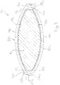
- Fig. 1 discloses a section of a pelt board 1 having a first major side 2 and an opposed second major side 3 and additionally a first lateral side 4 and an opposite second lateral side 5.
- the first major side 2 and the second major side 3 are convex in a cross-sectional view as is more clearly shown in Fig. 2a and Fig. 2b .
- a tubular mink pelt 6 is mounted and longitudinally stretched on the pelt board 1.
- the pelt 6 has an inner pelt side 7 being the flesh side, and an outer pelt side 8 being the fur side.
- the outer pelt side shown in Fig. 1 is the back 9 of the pelt 6, and the central longitudinal part of back 9 continues into the tail 10 and is the strongest part of the pelt.
- the pelt 6 is retained, i.e. secured, to the pelt board by means of a first example of a pelt-retaining device 11 according to the present invention.
- the pelt-retaining device 11 comprises a first elongated element 13 and a second elongated element 12.
- the first and second elongated elements are identical and each has the general shape of an elongated strip with rectangular cross-section and a length, a width, and a thickness.
- Each elongated element 12,13 has a length allowing the elongated element to extend beyond each of the lateral sides of the belt board over a certain length thereof when arranged transversely of the pelt board, so that the elongated elements and thereby the pelt-retaining device can be used to fix essentially any pelt size intended to be stretched and dried on the pelt board in question.
- Each elongated element 12,13 is made of a first polymeric material having a relatively high rigidity, strength, and hardness, such as e.g. polyoxymethylene (POM), forming the outer surface 16 of the elongated element and a softer polymeric material or rubber material forming the inner surface 17 of the elongated element.
- POM polyoxymethylene
- each elongated element 12,13 has a first longitudinally outer end portion 14 and a second longitudinally outer end portion 15.
- a cylindrical formation 19 is formed at each outer end portion of each elongated element at the outer surface 16 of the elongated element 12,13.
- the cylindrical formations 19 extend in the direction of the width of the elongated elements and are each provided with a through-going bore 20.
- a groove 21 is formed between each cylindrical formation and the adjacent outer surface 16 of elongated element 12,13.
- the elongated elements 12, 13 are elastically bendable 12, 13 to allow them to be bent when they are arranged transversely of the pelt board 1 and opposite each other on respective sides of the pelt board, and the end potions 14, 15 of the first elongated element 12 are moved towards the end portions 14, 15 of the second elongated element 13.
- the inner surface 17 of the first elongated element 12 is brought into retaining engagement with the outer surface of the pelt portion arranged on the first major side 2 of the pelt board 1
- the inner surface 17 of the second elongated element 13 is brought into retaining engagement with the outer surface of the pelt portion arranged on the second major surface 3 of the pelt board 1.
- the elongated elements apply a pressure on the pelt to press the pelt into retaining engagement with the outer surface of the pelt board.
- the pressure applied to the pelt when the elongated elements 12, 13 are bent over the convex major sides 1, 2 of the pelt board 1 is highest at the longitudinally central portion of said sides and decreases towards the lateral sides 4, 5 of the pelt board 1.
- This effect is advantageous in that the longitudinally central portion of the back of the pelt is the strongest part, and this portion of the back of the pelt is subjected to the highest pressure towards the pelt board.
- the pelt-retaining device 11 comprises a first connecting arrangement 22 and a second connecting arrangement 23.
- the first connecting arrangement 22 is configured for connecting the first outer end portion 14 of the first elongated element 12 with the first outer or second outer end portion 14,15 of the second elongated element 13.
- the second connecting arrangement 23 is configured for connecting the second outer end portion 15 of the first elongated element 12 with the first or second outer end portion of the second elongated element 13.
- the object of the connecting arrangements is to maintain the elongated elements in the above-described bent position after stretching of the pelt and during drying of the pelt and thereby secure the pelt to the pelt board.
- the first connecting arrangement 22 is a first tie 24 in the form of a metal binding wire configured to be wound around the first outer end portion 14 of the first elongated element 12 and one of the end portions of the second elongated element and tightened and locked by twisting the outer ends of the tie to maintain the elongated elements in the bend state
- the second connection arrangement 23 is a second tie 25 in the form of a metal binding wire configured to be wound around the second outer end portion 15 of the first elongated element 12 and the other one of the outer end portions of the second elongated element 13 and tightened and locked by twisting the outer ends of the tie to maintain the elongated elements in the bend state.
- Fig. 5 discloses that the first and second connection arrangements could comprise a tie in the form of a cable tie 26 instead of comprising a tie in the form of a metal binding wire.
- the above-described example of a pelt-retaining device was configured for retaining pelts on pelt boards having convex major sides.
- the modified pelt-retaining device 11a is configured to retain pelts on a traditional pelt board having a rectangular cross-section and parallel major sides 2a, 3a.
- the modified retaining device 11a only differs from the above-described pelt-retaining device 11 in that the first and second elongated elements 12a, 13a are not essentially straight but are instead convex curved.
- the elongated elements 12a, 13a of the modified pelt-retaining device 11a can be considered a convex bent version of the above-described elongated elements.
- the suffix a has therefore been added to the reference numerals of the above-described example of the invention.
- the elongated elements 12a og 13a of the modified pelt-retaining device 11a is shown in Fig 3a on opposite sides of the pelt board. 1a.
- the elongated elements are convexly curved such that the inner surface 17a has convex shape and the outer surface 16a a concave shape.
- the inner surface is provided with hemispherical protrusions 18a.
- Each elongated element 12a, 13a is at the first and the second longitudinally outer end portion 14a, 15a provided with the cylindrical formation 19a provided with a through-going bore 20a.
- Each of the first and the second connecting arrangements 22a and 22b comprises a tie in the form of a metal binding wire 24a, 25a.
- the adjacent outer end portions 14a, 15a of the elongated elements 12a, 13a are moved towards each other.
- the elongated elements are straightened to bring the inner surface 17 of each elongated element into contact with the pelt of the fur and thereby bringing the inner surface of the pelt into retaining engagement with the first and the second major surface 2a, 3a of the pelt board 1a, as shown in Fig. 3b .
- the central longitudinal portion of the pelt board and the central longitudinal portion of the back of the pelt is advantageously subjected to a higher pressure towards the pelt board than the more lateral portion of the pelt.
- the tie 24a, 26a of the first and second connecting arrangements 22a and 23a are wound around the respective adjacent outer end portions 14a, 15a, tightened and locked by twisting the outer ends of the tie in the form of a binding wire as described above.
- the stretched pelt secured to the pelt board is now ready for drying.
- Fig. 6a and 6b illustrate a second example of a peltretaining device 116 according to the invention.
- the first and second elongated elements 12, 13 are identical to the first and second elongated elements described above with reference to Figs. 1 , 2a . 2b and 4 .
- the second example only differs from the first example in that the first and second connection arrangements each is a U-shaped connecting part 29 having two essentially parallel legs 27, 28 configured and shaped to be inserted in the respective one of the through-going bores 20 in the respective one set of adjacent end portions of the elongated elements 12,13 after the elongated elements have been bent to a position where the pelt is secured to the pelt board.
- the engagement of the legs 27of the U-shaped connecting part in the bores 20 maintains the elongated elements in the position where the pelt is secured to the pelt board.
- Figs. 7a and 7b disclose a schematically perspective view of the connection arrangement of a third example of a pelt-retaining device according to the present invention.
- the third example corresponds essentially to the above-described first and second example apart from the connecting arrangements for connecting adjacent outer end portions of a first and a second elongated element and apart from the structures or features of said outer end portions of the first and second elongated element of said elongated elements.
- the suffix b has therefore been added to the reference numerals of the above-described example of the invention for identifying identical or similar features or parts.
- the pelt-retaining device comprises a first elongated element 32 and a second elongated element 33.
- the elongated elements 32 and 33 are only partly shown, but they are identical.
- Each connecting arrangement of the pelt-retaining device comprises a primary connecting part 34 and a secondary connecting part 35.
- the first outer end portion 14b of each elongated element is provided with the primary connection part 34 and the second outer end portion 15b of each elongated element is provided with the secondary connection part 35.
- the primary connection part 34 is a ratchet bar or tie 36 with a single tooth 37.
- the secondary connection part is a pawl 38 configured to preferably releasably engage the tooth 37 e.g.
- the pawl 38 is provided on the outer wall 39 of a through-going opening 40 at the outer end of the elongated element 32 in question.
- the ratchet tooth and the pawl of the adjacent outer end portion of the elongated elements arranged on opposite sides of the pelt board are brought into engagement after the elongated elements have been moved into the state where the pelt is secured to the pelt board. Thereafter, the pelt on the pelt board can be dried.
- the modified pelt-retaining device comprises a first elongated element 32c and a second elongated element 33c.
- the elongated elements 32c and 33c are identical.
- Each connecting arrangement of the pelt-retaining device comprises a primary connecting part 34c and a secondary connecting part 35c.
- the first outer end portion 14c of each elongated element is provided with the primary connection part 34c, and the second outer end portion 15c of each elongated element is provided with the secondary connection part 35c.
- the primary connection part 34c is a ratchet bar or ratchet tie 36c with a plurality of consecutively arranged teeth 37c.
- the secondary connection part is a pawl 38c configured to preferably releasably engage a tooth 37c e.g.
- the pawl 38c is provided on the outer wall 39c of a through-going opening 40c at the outer end of the elongated element 32c in question.
- a ratchet mechanism having a ratchet bar or tie with a plurality of consecutively arranged teeth allows for adjusting the pressure applied to the pelt by the elongated element, and further allows for obtaining the desired pressure on the pelt over a desired length of the pelt board so that the pelt-retaining device can be used for at least essentially all the sizes of pelts for which the pelt board is intended to be used.
Landscapes
- Engineering & Computer Science (AREA)
- Mechanical Engineering (AREA)
- Chemical & Material Sciences (AREA)
- Organic Chemistry (AREA)
- Clamps And Clips (AREA)
Description
- The present invention relates to a retaining device and a method for, after stretching and during drying, retaining a stretched tubular pelt, such as a mink pelt having an inner pelt side and an outer pelt side to a predetermined transversely circumferential section of a pelt board having a first major side and opposite second major side and a first lateral side and an opposite second lateral side.
- After skinning and scraping of the flesh side of pelts, such as mink pelts, the pelt is mounted on a pelt board and longitudinally stretched and thereafter fixed or retained to the pelt board in order to maintain the increased the length of the pelt during drying of the pelt. Frequently, a bag or sleeve of a fat-absorbing material, such as paper, is arranged on the pelt board prior to mounting and stretching the pelt on the pelt board.
- A traditional pelt board is a flat board of wood or a similar suitable material having parallel first and second major sides and lateral sides which are essentially parallel at the lower part of the pelt board and taper inwardly at the upper part of the pelt board. The pelt is in the stretched state fixed to the pelt board by means of staples at the lower end or tail end of the pelt.
- Today, most pelt boards have convex major sides provided with openings and are additionally circumferentially expandable, thereby allowing an easier removal of the pelt from the pelt board after drying.
- Different retaining or fixing methods and means have been proposed for retaining the pelt to the above pelt boards after stretching of the pelt.
-
EP 1 285 094 B1 -
EP 1 723 262 B1 -
EP 3 034 630 A1 - The strongest part of a pelt is the central longitudinal part of the back of the pelt body and the tail being an extension of said central longitudinal part. The central longitudinal part of the back of the pelt body can therefore be subjected to higher stretching stress than the rest of the pelt, especially than the lower belly portion of the pelt. A higher fixation stress is therefore in general needed for maintaining the central part of the pelt in the stretched position during drying than for the rest of the pelt. This is especially the case when pelts including the central longitudinal back part are highly stretched for obtaining the optimal length of the pelt.
- The object of the present invention is to provide a retaining device allowing for a reliable fixation of the pelt to the pelt board, especially a reliable fixation of the central longitudinal part of the back of the pelt during drying after stretching.
- A further object of the present invention is to provide a retaining device allowing for providing the fixation stress of the pelt towards the pelt board that is higher at the central longitudinal part of at least one of the major sides of the pelt board, said major side being the side of the pelt board on which the back portion of the pelt is to be mounted.
- An additional object of the present invention is to provide a retaining device allowing for adjusting the force or stress by which the pelts are pressed against the pelt board.
- A further object of the present invention is to provide a retaining device useable over a length of the pelt board over which the length of the circumference of the pelt board varies.
- An additional object of the present invention is to provide a reusable retaining device.
- The present invention provides a pelt-retaining device for surrounding and retaining a stretched tubular pelt having an outer and an inner pelt side to a predetermined transversely circumferential section of a pelt board having a first major side and an opposite second major side, and a first lateral side and an opposite second lateral side, comprising:
- a first elongating element and a second elongated element, each having a length, a width and a thickness
- the first elongated element having a first longitudinally outer end portion and a second longitudinally outer end portion and an inner surface and an opposite outer surface, and
- the second elongated element having a first longitudinally outer end portion and a second longitudinally outer end portion and an inner surface and an opposite outer surface,
- the first and second elongated elements each having a longitudinal length allowing the end portions thereof to extend beyond the first and second lateral side, respectively, of the pelt board in a predetermined lateral section of the pelt board, and
- a first connecting arrangement and a second connecting arrangement
- the first connecting arrangement being configured for connecting the first outer end portion of the first elongated element with the first or second outer end portion of the second elongated element, and
- the second connecting arrangement being configured for connecting the second outer end portion of the first elongated element with the first or second outer end portion of the second elongated element,
- The inner surfaces of the first and second elongated elements are preferably provided with such a shape relative to the shape of the first and second major surfaces of the pelt board type for which they are to be used that, when they are bend and their opposite end surfaces is moved towards each other, the central portions of the elongated elements are first brought into engagement with the pelt part at the longitudinally central part of the major sides of the pelt board and thereby also the longitudinally central part of the back part of the pelt. As a result, the longitudinally central part of the back of the pelt is pressed harder against the pelt board than more lateral parts of the pelt, and an optimal fixation or securing of the pelt to the pelt board is thereby obtained.
- For the presently most common used pelt boards having convex major surfaces, the inner surface of the elongated elements can be generally planar or convex. However, in this case, the inner surface of the elongated elements can also have a generally concave curvature with a radius of curvature larger than the radius of curvature of the pelt board in the predetermined transverse section of the pelt board.
- For the traditional pelt boards of wood or similar material, it is advantageous that the inner surface of the elongated elements has a generally convex curvature. Thereby, the elongated elements press the pelt harder against the longitudinally central part of the pelt board than against the more lateral parts of the pelt board.
- The inner and outer surface of each longitudinal element can be generally parallel.
- According to the invention, the elongated elements of the pelt-retaining device can advantageously have the shape of a strip with rectangular cross-section.
- The length of the elongated elements is preferably considerably longer than the width thereof, and the width of the elongated elements can be greater than the thickness thereof.
- Additionally, according to the invention, the inner surface or the elongated elements can have a texture comprising a plurality of protrusions, such as a plurality of linear or punctual protrusions. Thereby, an improved grip is obtained between the elongated elements and pelt and pelt and pelt board.
- The texture of the inner surface of the elongated elements can comprise a plurality of hemispherical protrusions.
- Further, according to the invention the elongated elements can be formed of a polymeric material having a relatively high rigidity, strength, and hardness, e.g. polyoxymethylene (POM).
- The elongated elements can be formed by injection moulding.
- The elongated elements can also be formed of or comprise an elongated element of spring steel or another springy material.
- Furthermore, according to the invention, the elongated elements can be provided with a coating forming the inner surface thereof, the coating being of a relatively soft polymeric material or rubber material being softer than other parts of the elongated elements.
- The elongated elements can be provided with a softer coating by two-component injection moulding or by the softer coating being connected to or supplied to a separately formed elongated element.
- The soft material provides for an improvement of the grip between the elongated elements and the pelt, and also between the pelt and the pelt board as the soft material can adapt to the surface structure of the major sides of the pelt board.
- According to a first example of the present invention, the first connecting arrangement comprises a first tie configured to be wound around the first outer end portion of the first elongated element and one of the outer end portions of the second elongated element and tightened, and the second connecting arrangement comprises a second tie configured to be wound around the second outer end portion of the first elongated element and the other one of outer end portions of the second elongated element and tightened, the outer end portions of each of the elongated elements being optionally provided with positioning means, such as a recess or a protrusion, in order to control the position of the tie.
- When the desired pressure of the elongated elements against the pelt is obtained, the first and second ties are locked to maintain the elongated element in the bend shape providing the desired pressure of the elongated elements against the pelt. The desired pressure is maintained until the ties are removed, e.g. by being cut after drying of the pelt.
- The positioning means can e.g. be provided in the outer surface of the elongated elements.
- The tie can be a binding wire, a tying wire, a cable tie, a zip tie etc. of metal or a polymeric material.
- Further, according to a second example of the present invention, each connecting arrangement comprises a guide means provided in each outer end portion of each longitudinal element, such as a transverse groove or a transverse bore, and a U-shaped item having two essentially parallel legs configured and shaped to be preferably releasably received in respective guide means in the outer end portions of two adjacent longitudinal elements.
- In the bent state of the elongated elements against the pelt, the legs of the U-shaped item are brought into engagement with respective guide means in the outer end portion of the respective elongated element. Thereby, the pressure of the elongated elements against the pelt is maintained until the U-shaped connecting part is disengaged after drying of the pelt.
- Additionally, according to a third example of the present invention, each connecting arrangement comprises a primary connecting part comprising at least one first engagement means, optionally several consecutively arranged first engagement means, and a secondary connecting part comprising a second engagement means configured to preferably releasably engage the at least one first engagement means, the primary connecting part being integrated with the first end portion of the first elongated element, and the secondary connecting part being integrated with the first or second outer end portion of the second elongated element.
- In the desired bend state of the elongated elements, the primary connection part and the secondary part of the first connection arrangement are brought into engagement, and the primary connection part and the secondary part of the second connection arrangement are brought into engagement. Thereby, the desired pressure of the elongated elements against the pelt on the pelt board is obtained and can be maintained until the pelt has been dried. By providing the primary connecting part of each connecting arrangement with several consecutively arranged first engagement means, the desired pressure of the elongated elements against the pelt on the pelt board can be obtained over a desired length of the pelt board with varying width.
- In the above mentioned third example of the present invention, the first elongated element can comprise a second primary connecting part with at least one first engagement means being integrated with the second outer end portion of the first elongated element, and the second elongated element can comprise a secondary connecting part with a second engagement means being integrated with the first end portion of the second elongated element and a secondary connecting part with a second engagement means being integrated with second outer end portion of the second elongated element.
- Thereby, the first elongated element is provided with a primary connection part at each outer end portion, and the second outer connection element is provided with a secondary connection part at each outer end portion.
- Alternatively, in the above-mentioned third example of the present invention, the first elongated element can comprise a secondary connecting part with a second engagement means being integrated with the second outer end portion of the first elongated element, and the second elongated element can comprise a secondary connecting part with a second engagement means being integrated with the first outer end portion of the second elongated element and a primary connecting part with at least one first engagement means and being integrated with the second outer end portion of the second elongated element.
- In the above case, the first and second elongated elements can advantageously be identical.
- In the above-mentioned example of the invention, the primary and secondary connection parts can advantageously be integrally formed with the respective outer end portions of the respective first and second elongated element.
- In the above-mentioned example according to any of the
claims 8 to 10 of the present invention, a primary and a second primary connecting part with at least one first connection means can be a ratchet bar or tie with at least one tooth and preferably several consecutive teeth, and the secondary connecting part comprising a second engagement means can be a pawl configured to preferably releasably engage the at least one tooth. - In other words, each connecting arrangement can comprise a ratchet mechanism comprising a ratchet bar or tie provided with at least one tooth, preferably several consecutively arranged teeth, each having a ramp face followed by a vertical face, and a pawl means configured to ride up along the ramp face and drop down behind the vertical face, the ratchet bar or tie being integrated with the first end portion of the first elongated element, and the pawl means being integrated with the first or second outer end portion of the second elongated element.
- The pawl means of the ratchet mechanism can be arranged at an inner wall of a through-going opening of an outer end portion of the elongated element in question in a way similar to that known from cable ties.
- The first elongated element can comprise a second ratchet bar or tie being integrated with the second outer end portion of the first elongated element, and the second elongated element can comprise a pawl means being integrated with the first outer end portion of the second elongated element, and a pawl means being integrated with the second outer end portion of the second elongated element.
- Alternatively, the first elongated element can comprise a pawl means being integrated with the second outer end portion of the first elongated element, and the second elongated element can comprise a pawl means being integrated with the first outer end portion of the second elongated element, and a ratchet bar or tie being integrated with the second outer end portion of the second elongated element.
- In the above case, the first and second elongated elements can advantageously be identical.
- The ties and pall means can be integrally formed with the respective outer end portions of the respective first and second elongated elements.
- In the above-mentioned third example according to any of the
claims 8 to 10 of the present invention, a primary and a second primary connecting part with at least one first connection means can be a band or tie with at least one and preferably several consecutive holes, and a secondary connecting part comprising a second engagement means can be a stud or button configured to preferably releasably engage the at least one hole. - It should be noted that a primary connecting part with at least one first connection means can also be a band or tie with at least one and preferably several consecutive studs or buttons, and a secondary connecting part comprising a second engagement means can be a hole configured to preferably releasably engage the at least one stud or button.
- In other words, each connecting arrangement can comprise a band or tie provided with at least one hole, preferably several consecutive arranged holes, and a stud or button configured to be releasably received in the at least one hole, the band or tie being integrated with the first end portion of the first elongated element, and the stud or button being integrated with the first or second end of the outer end portion of the second elongated element.
- The first elongated element can comprise a second band or tie being integrated with the second outer end portion of the first elongated element, and the second elongated element can comprise a stud or button being integrated with the first outer end portion of the second elongated element, and a stud or button being integrated with the second outer end of the second elongated element.
- Alternatively, the first elongated element can comprise a stud or button being integrated with the second outer end portion of the first elongated element, and the second elongated element can comprise a stud or button being integrated with the first outer end portion of the second elongated element, and a band or tie being integrated with the second outer end portion of the second elongated element.
- In the above case, the first and second elongated elements can advantageously be identical.
- The ties and studs can be integrally formed with the respective outer end portions of the respective first and second elongated element.
- In the above-mentioned third example according to any of the
claims 8 to 10 of the present invention, a primary and a second primary connecting part with at least one first connection means can be a band or tie with at least one and preferably several consecutive hooks, and a secondary connecting part comprising a second engagement means can be an eye configured to be preferably releasably engaged by the at least one hook. - It should be noted that a primary connecting part with at least one first connection means can also be a band or tie with at least one and preferably several consecutive eyes, and a secondary connecting part comprising a second engagement means can be a hook configured to preferably releasably engage the at least one eye.
- In other words, each connecting arrangement can comprise a tie or band provided at least one hook, preferably several consecutive arranged hooks, and an eye configured to be releasably engaged by the at least one hook, the hook being integrated with the first end portion of the first elongated element, and the eye being integrated with the first or second end of the outer end portion of the second elongated element.
- The first elongated element can comprise a second tie or band provided with at least one hook, preferably several consecutive arranged hooks, and being integrated with the second outer end portion of the first elongated element, and the second elongated element can comprise an eye being integrated with the first outer end portion of the second elongated element and an eye being integrated with the second outer end of the second elongated element.
- Alternatively, the first elongated element can comprise an eye being integrated with the second outer end portion of the first elongated element, and the second elongated element can comprise an eye being integrated with the first outer end portion of the second elongated element and a tie or band provided with at least one hook, preferably several consecutive arranged hooks, and being integrated with the second outer end portion of the second elongated element.
- In the above case, the first and second elongated elements can advantageously be identical.
- The ties and eyes can be integrally formed with the respective outer end portions of the respective first and second elongated element.
- Further, the present invention provides a method for retaining a stretched tubular pelt having an outer and an inner pelt side on a predetermined transversely circumferential section of a pelt board having a first major side and an opposite second major side and a first lateral side and an opposite second lateral side, comprising:
- arranging the tubular pelt on the pelt board with the inner pelt side being the flesh side facing the first and the second major side of the pelt board, and the outer pelt side being the fur side facing outwardly,
- providing a first elastically bendable elongated element and a second elastically bendable elongated element,
- the first elongated element having a first longitudinally outer end portion and a second longitudinally outer end portion and an inner surface and an opposite outer surface, and
- the second elongated element having a first longitudinally outer end portion and a second longitudinally outer end portion and an inner surface and an opposite outer surface,
- the first and second elongated element each having a longitudinal length allowing the end portions thereof to extend beyond the first and second lateral side, respectively, of the pelt board in a predetermined lateral section of the pelt board,
- arranging the elongated elements opposite each other on respective sides of the pelt at the predetermined transversely circumferential section of a pelt board,
- moving the opposite end portions of the first elongated element transversely towards the adjacent opposite end portions of the second elongated element and thereby bending the elastically bendable elongated elements and bringing the inner surface of the first elongating element into retaining engagement with the outer side of the pelt and the inner surface of the second elongated element into retaining engagement with the outer side of the pelt and the inner surface of the pelt into retaining engagement with the first and second major side of the pelt board,
- interconnecting the transversely adjacent opposite end portions of the first and second elongated elements by means of a first and a second connecting arrangement to maintain the retaining engagement between the inner surfaces of the elongated elements and the outer pelt side and to maintain the retaining engagement between the inner pelt side and the first and second major side of the pelt board.
- Finally, the present invention relates to the use of a pelt-retaining device according to the present invention for carrying out the method according to the present invention
- Embodiments of the invention will be described in more detail in the following with regard to the accompanying figures. The figures show one way of implementing the present invention and are not to be construed as being limiting to other possible embodiments falling within the scope of the attached claim set.
-
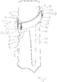
Fig. 1 illustrates in a schematically perspective view a reusable pelt board having opposite convex major sides and on which pelt board, a tubular pelt has been mounted and longitudinally stretched, and being at its lower end retained or secured to the pelt board by means of a first example of a pelt-retaining device according to the invention, -
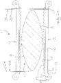
Fig. 2a schematically illustrates a cross-sectional view ofFig. 1 , the pelt having been omitted for illustrative purposes, and the pelt-retaining device not yet having been brought into retaining engagement with the pelt, -
Fig. 2b schematically illustrates a cross-sectional view similar to that ofFig. 2a , but where the pelt-retaining device has been brought into a position where the omitted pelt is retained to the pelt board, -
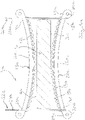
Fig. 3a is a schematically cross-sectional view corresponding to that ofFig. 2a , but where the pelt board is a traditional pelt of e.g. wood having a rectangular cross section, and where the pelt-retaining device has not yet been brought into engagement with the omitted pelt on the pelt board, -
Fig 3b schematically illustrates a cross-sectional view similar to that ofFig. 3a , but where the pelt-retaining device has been brought into a position where the omitted pelt is retained to the pelt board, -
Fig.4 is a schematically perspective view of the connection arrangement shown inFig. 1 to 3 between adjacent outer end portions of the elongated element of the first embodiment of the pelt-retaining device according to the invention, the connection arrangement comprising a binding or tying wire of metal being wound around the outer end portions of the adjacent outer end portions and locked by being twisted, -
Fig. 5 is a schematically perspective view corresponding to that ofFig. 4 , but where the tie is a cable or zip tie instead of a binding or tying wire. -
Fig. 6a is a schematically perspective view of the connection arrangement of a second example pf a reusable pelt-retaining device according to the present invention, adjacent outer end portions of elongated elements of the pelt-retaining device having not yet been connected, -
Fig. 6b is a schematically perspective view of the connection arrangement shown inFig. 6a , but where the adjacent outer end portions of elongated elements of the pelt-retaining device having have been connected by means of a U-shaped item, -
Fig. 7a is a schematically perspective view of the connection arrangement of a third example of a reusable pelt-retaining device according to the present invention, adjacent outer end portions of elongated elements of the pelt-retaining device having not yet been connected, the connection arrangement being a ratchet mechanism comprising a ratchet bar with a single tooth at the outer end portion of one of two adjacent end portions, and the other end portion comprises a pawl mean, the tooth and the pawl means not yet being in mutual engagement, -
Fig. 7b is a schematically perspective view of the connection arrangement shown inFig. 7a , but where the tooth of the ratchet bar and the tooth of pawl means have been brought into mutual engagement, -
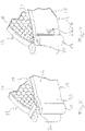
Fig. 8 is a cross-sectional view of a pelt board and a third embodiment of a reusable pelt-retaining device according to the invention, the connecting arrangement thereof being an improved modification of the connection arrangement shown inFig. 7a and Fig. 7b . as the ratchet bar comprises several consecutive teeth, the ratchet bars having not yet been brought into engagement with the respective adjacent pawl means, -
Fig. 9 is a schematically perspective view corresponding toFig. 8 , but where a tooth of the ratchet bar and a tooth of the pawl means have been brought into mutual engagement and the elongated elements pressed against the not shown pelt and the pelt thereby being pressed against the pelt board and thereby retained to the pelt board, and -
Fig. 10 illustrates in a schematically perspective view of the situation illustrated inFig. 9 , but where it is shown that the pelt-retaining device according to the invention surrounds the lower end of the pelt and presses the lower end of the pelt towards the pelt board and thereby retains or secures the pelt to the pelt board. -
Fig. 1 discloses a section of apelt board 1 having a firstmajor side 2 and an opposed secondmajor side 3 and additionally a first lateral side 4 and an opposite secondlateral side 5. The firstmajor side 2 and the secondmajor side 3 are convex in a cross-sectional view as is more clearly shown inFig. 2a andFig. 2b . - A tubular mink pelt 6 is mounted and longitudinally stretched on the
pelt board 1. The pelt 6 has an inner pelt side 7 being the flesh side, and anouter pelt side 8 being the fur side. The outer pelt side shown inFig. 1 is theback 9 of the pelt 6, and the central longitudinal part ofback 9 continues into the tail 10 and is the strongest part of the pelt. - The pelt 6 is retained, i.e. secured, to the pelt board by means of a first example of a pelt-retaining device 11 according to the present invention. The pelt-retaining device 11 comprises a first
elongated element 13 and a secondelongated element 12. The first and second elongated elements are identical and each has the general shape of an elongated strip with rectangular cross-section and a length, a width, and a thickness. Eachelongated element elongated element outer surface 16 of the elongated element and a softer polymeric material or rubber material forming theinner surface 17 of the elongated element. The inner surface has a texture of comprising a plurality of protrusions beinghemispherical protrusions 18 as most clearly shown inFig 2a . Additionally, eachelongated element outer end portion 14 and a second longitudinally outer end portion 15. Acylindrical formation 19 is formed at each outer end portion of each elongated element at theouter surface 16 of theelongated element cylindrical formations 19 extend in the direction of the width of the elongated elements and are each provided with a through-goingbore 20. Agroove 21 is formed between each cylindrical formation and the adjacentouter surface 16 ofelongated element - As disclosed in
Fig. 1 and as it appears by comparingFig. 2a andFig. 2b , theelongated elements pelt board 1 and opposite each other on respective sides of the pelt board, and theend potions 14, 15 of the firstelongated element 12 are moved towards theend portions 14, 15 of the secondelongated element 13. By this bending of theelongated elements inner surface 17 of the firstelongated element 12 is brought into retaining engagement with the outer surface of the pelt portion arranged on the firstmajor side 2 of thepelt board 1, and theinner surface 17 of the secondelongated element 13 is brought into retaining engagement with the outer surface of the pelt portion arranged on the secondmajor surface 3 of thepelt board 1. Additionally, by the above bending of the elongated elements, the elongated elements apply a pressure on the pelt to press the pelt into retaining engagement with the outer surface of the pelt board. - The pressure applied to the pelt when the
elongated elements major sides pelt board 1 is highest at the longitudinally central portion of said sides and decreases towards thelateral sides 4, 5 of thepelt board 1. This effect is advantageous in that the longitudinally central portion of the back of the pelt is the strongest part, and this portion of the back of the pelt is subjected to the highest pressure towards the pelt board. - Additionally, the pelt-retaining device 11 comprises a first connecting
arrangement 22 and a second connectingarrangement 23. The first connectingarrangement 22 is configured for connecting the firstouter end portion 14 of the firstelongated element 12 with the first outer or secondouter end portion 14,15 of the secondelongated element 13. The second connectingarrangement 23 is configured for connecting the second outer end portion 15 of the firstelongated element 12 with the first or second outer end portion of the secondelongated element 13. The object of the connecting arrangements is to maintain the elongated elements in the above-described bent position after stretching of the pelt and during drying of the pelt and thereby secure the pelt to the pelt board. - In the first example of the invention shown in
Figs.1 and2a and2b and4 ., the first connectingarrangement 22 is afirst tie 24 in the form of a metal binding wire configured to be wound around the firstouter end portion 14 of the firstelongated element 12 and one of the end portions of the second elongated element and tightened and locked by twisting the outer ends of the tie to maintain the elongated elements in the bend state, and thesecond connection arrangement 23 is asecond tie 25 in the form of a metal binding wire configured to be wound around the second outer end portion 15 of the firstelongated element 12 and the other one of the outer end portions of the secondelongated element 13 and tightened and locked by twisting the outer ends of the tie to maintain the elongated elements in the bend state. -
Fig. 5 discloses that the first and second connection arrangements could comprise a tie in the form of acable tie 26 instead of comprising a tie in the form of a metal binding wire. - The above-described example of a pelt-retaining device was configured for retaining pelts on pelt boards having convex major sides. Below and by reference to
Fig. 3a and3b a modification of the above-described pelt-retaining device is described. The modified pelt-retaining device 11a is configured to retain pelts on a traditional pelt board having a rectangular cross-section and parallelmajor sides elongated elements elongated elements - The
elongated 13a of the modified pelt-retaining device 11a is shown inelements 12a ogFig 3a on opposite sides of the pelt board. 1a. The elongated elements are convexly curved such that theinner surface 17a has convex shape and theouter surface 16a a concave shape. The inner surface is provided withhemispherical protrusions 18a. Eachelongated element outer end portion cylindrical formation 19a provided with a through-going bore 20a. - Each of the first and the second connecting
arrangements 22a and 22b comprises a tie in the form of ametal binding wire - After the elongated elements have been arranged on opposite sides of the pelt board as shown in
Fig. 3a , the adjacentouter end portions elongated elements inner surface 17 of each elongated element into contact with the pelt of the fur and thereby bringing the inner surface of the pelt into retaining engagement with the first and the secondmajor surface Fig. 3b . Due to the convex shape of the pelt board, the central longitudinal portion of the pelt board and the central longitudinal portion of the back of the pelt is advantageously subjected to a higher pressure towards the pelt board than the more lateral portion of the pelt. - In the retaining or securing state of the elongated elements, the
tie 24a, 26a of the first and second connectingarrangements outer end portions -
Fig. 6a and 6b illustrate a second example of a peltretaining device 116 according to the invention. The first and secondelongated elements Figs. 1 ,2a .2b and4 . The second example only differs from the first example in that the first and second connection arrangements each is a U-shaped connectingpart 29 having two essentiallyparallel legs bores 20 in the respective one set of adjacent end portions of theelongated elements bores 20 maintains the elongated elements in the position where the pelt is secured to the pelt board. -
Figs. 7a and 7b disclose a schematically perspective view of the connection arrangement of a third example of a pelt-retaining device according to the present invention. The third example corresponds essentially to the above-described first and second example apart from the connecting arrangements for connecting adjacent outer end portions of a first and a second elongated element and apart from the structures or features of said outer end portions of the first and second elongated element of said elongated elements. The suffix b has therefore been added to the reference numerals of the above-described example of the invention for identifying identical or similar features or parts. - In the third example of the present invention, the pelt-retaining device comprises a first
elongated element 32 and a secondelongated element 33. Theelongated elements part 34 and a secondary connectingpart 35. The firstouter end portion 14b of each elongated element is provided with theprimary connection part 34 and the second outer end portion 15b of each elongated element is provided with thesecondary connection part 35. Theprimary connection part 34 is a ratchet bar or tie 36 with asingle tooth 37. The secondary connection part is apawl 38 configured to preferably releasably engage thetooth 37 e.g. by riding up along the leading face of thetooth 37 and drop down behind the trailing face of thetooth 37 of theratchet bar 36. As shown inFigs. 7a and 7b , thepawl 38 is provided on theouter wall 39 of a through-going opening 40 at the outer end of theelongated element 32 in question. - Similar to what has been previously described, the ratchet tooth and the pawl of the adjacent outer end portion of the elongated elements arranged on opposite sides of the pelt board are brought into engagement after the elongated elements have been moved into the state where the pelt is secured to the pelt board. Thereafter, the pelt on the pelt board can be dried.
- Reference is now made to
Figs. 8 ,9 and10 disclosing an improved and important modification of the third example of the pelt-retaining device shown inFigs. 7a and 7b . - The modified pelt-retaining device comprises a first elongated element 32c and a second elongated element 33c. The elongated elements 32c and 33c are identical. Each connecting arrangement of the pelt-retaining device comprises a primary connecting part 34c and a secondary connecting part 35c. The first outer end portion 14c of each elongated element is provided with the primary connection part 34c, and the second
outer end portion 15c of each elongated element is provided with the secondary connection part 35c. The primary connection part 34c is a ratchet bar or ratchettie 36c with a plurality of consecutively arranged teeth 37c. The secondary connection part is a pawl 38c configured to preferably releasably engage a tooth 37c e.g. by riding up along the leading face of the tooth 37c and drop down behind the trailing face of the tooth 37c of the ratchet bar or ratchettie 36c. As most clearly seen inFig. 10 , the pawl 38c is provided on the outer wall 39c of a through-going opening 40c at the outer end of the elongated element 32c in question. - One of the advantages of a ratchet mechanism having a ratchet bar or tie with a plurality of consecutively arranged teeth is that such a ratchet mechanism allows for adjusting the pressure applied to the pelt by the elongated element, and further allows for obtaining the desired pressure on the pelt over a desired length of the pelt board so that the pelt-retaining device can be used for at least essentially all the sizes of pelts for which the pelt board is intended to be used.
- With reference to
Figs. 1 ,2a og 2b, the method according to the present invention is carried out as follows: - arranging a tubular pelt 6 on the
pelt board 1 with the inner pelt side 7 being the flesh side facing the first and the secondmajor side pelt board 1 and theouter pelt side 8 being the fur side facing outwardly, - providing a first elastically bendable
elongated element 12 and a second elastically bendableelongated element 13, - longitudinally stretching the pelt 6 on the pelt board,
- arranging the
elongated elements pelt board 1, - moving the
opposite end portions 14, 15 of the first elongated element transversely towards the adjacent opposite end portions of the second elongated element and thereby bending the elastically bendableelongated elements inner surface 17 of the first elongatingelement 12 into retaining engagement with theouter side 8 of the pelt 6 and theinner surface 17 of the secondelongated element 13 into retaining engagement with theouter side 8 of the pelt 6 and the inner surface 7 of the pelt 6 into retaining engagement with the first and secondmajor side pelt board 1. - interconnecting the transversely adjacent opposite end portions of the first and second
elongated element arrangement elongated elements major side pelt board 1. -
- 1, 1a,1c
- pelt board
- 2,2a
- first major side
- 3,3a
- second major side
- 4
- first lateral side
- 5
- second lateral side
- 6,6c
- tubular pelt
- 7
- inner pelt side
- 8
- outer pelt side
- 9
- back
- 10
- tail
- 11, 11a,11b,11c
- pelt retaining device
- 12,12a
- first elongated element
- 13,13a
- second elongated element
- 14,14a,14b,14c
- first longitudinally outer end portion
- 15,15a,15b, 15c
- second longitudinally outer end portion
- 16, 16a,16b,16c
- outer surface of elongated element
- 17,17a,17b,17c
- inner surface of elongated element
- 18,18a
- hemispherical protrusion
- 19,19a
- cylindrical formation
- 20,20a
- through-going bore
- 21,21a
- groove
- 22,22a
- first connecting device
- 23.23a
- second connecting device
- 24
- first tie
- 25
- second tie
- 26
- cable tie
- 27,28
- parallel legs
- 29
- U-shaped part
- 30 31 32,32c
- first elongated element
- 33,33c
- second elongated element
- 34,34c
- primary connection part
- 35,35c
- secondary connection part
- 36, 36c
- ratchet bar or tie
- 37,37c
- tooth
- 38,38c
- pawl
- 39,39c
- outer wall
- 40,40c
- through-going opening
Claims (15)
- A pelt-retaining device (11,11a,11b,11c) for surrounding and retaining a stretched tubular pelt (6,6c) having an outer and an inner pelt side to a predetermined transversely circumferential section of a pelt board (1,1a,1c) having a first major side (2,2a) and an opposite second major side (3,3a), and a first lateral side (4) and an opposite second lateral side (5), comprising:- a first elongating element (12,12a, 32,32c) and a second elongated element (13,13a, 33, 33c), each having a length, a width, and a thickness- the first elongated element (12,12a, 32, 32c) having a first longitudinally outer end portion (14,14a,14b,14c) and a second longitudinally outer end portion (15,15a,15b,15c) and an inner surface (17,17a,17b,17c) and an opposite outer surface (16,16a,16b,16c), and- the second elongated element (13,13a, 33,33c) having a first longitudinally outer end portion (14,14a,14b,14c) and a second longitudinally outer end portion (15,15a,15b,15c) and an inner surface (17,17a,17b,17c) and an opposite outer surface (16,16a,16b,16c),- the first and second elongated element (12,12a,32,32c; 13,13a,33,33c) each having a longitudinal length allowing the end portions thereof to extend beyond the first and second lateral side (4;5), respectively, of the pelt board (1,1a,1c) in a predetermined lateral section of the pelt board, and- a first connecting arrangement (22,22a) and a second connecting arrangement (23,23a),- the first connecting arrangement (22,22a) being configured for connecting the first outer end portion (14,14a,14b,14c) of the first elongated element (12,12a,32,32c) with the first or second outer end portion (14,14a,14b,14c; 15,15a,15b,15c) of the second elongated element (13.13a,33,33a), and- the second connecting arrangement (23,23a) being configured for connecting the second outer end portion (15,15a,15b,15c) of the first elongated element (12,12a,32,32c) with the first or second outer end portion (14,14a,14b,14c; 15,15a,15b,15c) of the second elongated element (13,13a,33,33c),characterized in that the first and second elongated elements (12,12a,32,32c, 13,13a,33,33c) are elastically bendable to allow bending of the elongated elements when the elongated elements are arranged opposite each other on respective sides of the pelt, and the opposite end portions of the first elongated element (12,12a, 32,32c) are moved towards the adjacent opposite end portions of the second elongated element (13,13a,33,33c) and thereby bringing the inner surface (17,17a,17b,17c) of the first elongating element (12,12a,32,32c) into retaining engagement with the outer side (8) of the pelt, and the inner surface (17,17a,17b,17c) of the second elongated element (13,13a,33,33c) into retaining engagement with the outer side (8) of the pelt, and the inner surface (7) of the pelt into retaining engagement with the first and second major side (2,2a; 3,3a) of the pelt board (1,1a,1c).
- A pelt-retaining device according to claim 1, wherein the elongated elements (12,12a,32,32c; 13,13a,33,33c) have the general shape of a strip with rectangular cross-section.
- A pelt-retaining device according to any of the preceding claims, wherein the inner surface (17,17a,17b,17c) of the elongated elements (12,12a,32,32c; 13,13a,3333c) has a texture comprising a plurality of protrusions such as a plurality of linear or punctual protrusions (18,18a).
- A pelt-retaining device according to any of the preceding claims and being formed of a polymeric material having a relatively high rigidity, strength, and hardness, e.g. polyoxymethylene (POM).
- A pelt-retaining device according to any of the preceding claims, wherein the elongated elements (12,12a,3232c; 13,13a,33,33c) are provided with a coating forming the inner surface thereof, the coating being of a relatively soft polymeric material or rubber material being softer than other parts of the elongated elements.
- A pelt-retaining device according to any of the preceding claims, wherein the first connecting arrangement (22,22a) comprises a first tie (24) configured to be wound around a first outer end portion (14,14a) of the first elongated element (12,12a) and one of the outer end portions of the second elongated element (23,23a) and tightened, and the second connecting arrangement (23,23a) comprises a second tie (25) configured to be wound around the second outer end portion (15,15a) of the first elongated element (12,12a) and the other one of outer end portions of the second elongated (13,13a) element and tightened, the outer end portions (14,14a,15,15a) of each of the elongated elements (12,12a; 13,13a) being optionally provided with positioning means, such as a recess or a protrusion, in order to control the position of the tie.
- A pelt-retaining device according to any of the preceding claims 1 to 5, wherein each connecting arrangement (22;23) comprises a guide means provided in the outer end portion of each longitudinal element, such as a transverse groove or a transverse bore (20), and a U-shaped connecting part (29) having two essentially parallel legs (27,28) configured and shaped to be preferably releasable received in respective guide means in the outer end portions of two adjacent longitudinal elements (12,13).
- A pelt-retaining device according to any of the preceding claims 1 to 5, wherein each connecting arrangement (22,23) comprises a primary connecting part (34,34c) comprising at least one first engagement means, optionally several consecutively arranged first engagement means, and a secondary connecting part (35,35c) comprising a second engagement means configured to preferably releasably engage the at least one first engagement means, the primary connecting part (34,34c) being integrated with the first end portion of the first elongated element (32,32c) and the secondary connecting part (35,35c) being integrated with the first or second outer end portion of the second elongated element (33,33c).
- A pelt-retaining device according to claim 8, wherein the first elongated element (32,32c) comprises a second primary connecting part (34,34c) with at least one first engagement means being integrated with the second outer end portion of the first elongated element (32,32c), and the second elongated element (33,33c) comprises a secondary connecting part (35,35c) with a second engagement means being integrated with the first end portion of the second elongated element (33,33c) and a secondary connecting part (35,35c) with a second engagement means being integrated with second outer end portion of the second elongated element (33,33c).
- A pelt-retaining device according to claim 8, wherein the first elongated element (32,32c) comprises a secondary connecting part (35,35c) with a second engagement means being integrated with the second outer end portion of the first elongated element (32,32c), and the second elongated element (33,33c) comprises a secondary connecting part (35, 35c) with a second engagement means being integrated with the first outer end portion of the second elongated element (33,33c) and a primary connecting part with at least one first engagement means and being integrated with the second outer end portion of the second elongated element (33,33c).
- A pelt-retaining device according to any of the preceding claims 8 to 10, wherein a primary and a second primary connecting part (34,34c) with at least one first connection means is a ratchet baror tie (36,36c) with at least one tooth (37,37c) and preferably several consecutive teeth, and a secondary connecting part (35,35c) comprising a second engagement means is a pawl (38,38c) configured to preferably releasably engage the at least one tooth (37,37c).
- A pelt-retaining device according to any of the preceding claims 8 to 10, wherein a primary and a second primary connecting part (34,34c) with at least one first connection means is a band or tie with at least one and preferably several consecutive holes, and a secondary connecting part (35,35c) comprising a second engagement means is a stud or button configured to preferably releasably engage the at least one hole.
- A pelt-retaining device according to any of the preceding claims 8 to 10, wherein a primary and a second primary connecting part (34,34c) with at least one first connection means is a band or tie with at least one and preferably several consecutive hooks, and a secondary connecting part (35,35c) comprising a second engagement means is an eye configured to be preferably releasably engage the at least one hook.
- A method for retaining a stretched tubular pelt (6,6c) having an outer and an inner pelt side (8;7) on a predetermined transversely circumferential section of a pelt board (1,1a,1c)during drying, the pelt board having a first major side(2,2a) and an opposite second major side (3,3a) and a first lateral side (4) and an opposite second lateral side (5), comprising:- arranging the tubular pelt (6,6c) on the pelt board with (1,1a,1c) the inner pelt side (7) being the flesh side facing the first and the second major side (2,2a; 3,3a) of the pelt board, and the outer pelt side (8) being the fur side facing outwardly,- providing a first elastically bendable elongated element (12,12a,32,32c) and a second elastically bendable elongated element (13,13a, 33,33c),- the first elongated element (12,12a,32,32c) having a first longitudinally outer end portion and a second longitudinally outer end portion, and an inner surface (17,17a,17b,17c) and an opposite outer surface (16,16a,16b,16c), and- the second elongated element (13,13a, 33,33c) having a first longitudinally outer end portion and a second longitudinally outer end portion, and an inner surface (17,17a,17b,17c) and an opposite outer surface(16,16a,16b,16c)- the first and second elongated element (12,12a,32,32c, 13,13a, 33,33c) each having a longitudinal length allowing the end portions thereof to extend beyond the first and second lateral side (4,5) of the pelt board (1,1a,1c), respectively, in predetermined lateral section of the pelt board,- arranging the elongated elements (12,12a,32,32c, 13,13a, 33,33c) opposite each other on respective sides of the pelt at the predetermined transversely circumferential section of a pelt board,- moving the opposite end portions of the first elongated element (12,12a,32,32c) transversely towards the adjacent opposite end portions of the second elongated element (13,13a, 33,33c) and thereby bending the elastically bendable elongated elements and bringing the inner surface (17,17a,17b,17c) of the first elongating element(12,12a,32,32c) into retaining engagement with the outer side (8 ) of the pelt, and the inner surface (17,17a,17b,17c) of the second elongated element (13,13a, 33,33c) into retaining engagement with the outer side (8) of the pelt, and the inner surface (7) of the pelt into retaining engagement with the first and second major side (2,2a, 3,3a) of the pelt board,- interconnecting the transversely adjacent opposite end portions of the first and second elongated element (12,12a,32,32c, 13,13a, 33,33c) by means of a first and a second connecting arrangement (22,22a, 23,23a) to maintain the retaining engagement between the inner surfaces of the elongated elements (12,12a,32,32c, 13,13a, 33,33c) and the outer pelt side and to maintain the retaining engagement between the inner pelt side and the first and second major side (2,2a, 3,3a) of the pelt board (1,1a,1c).
- Use of a pelt-retaining device according to any of the preceding claims 1 to 13 for retaining a stretched tubular pelt (6,6c) to a pelt board (1,1a,1c) during drying and for carrying out the method according to claim 14.
Priority Applications (3)
| Application Number | Priority Date | Filing Date | Title |
|---|---|---|---|
| EP18162047.7A EP3540079B1 (en) | 2018-03-15 | 2018-03-15 | Pelt-retaining device for retaining a pelt on a pelt board |
| DK18162047.7T DK3540079T3 (en) | 2018-03-15 | 2018-03-15 | SKIN RETAINING DEVICE FOR RETAINING A SKIN ON A TANE |
| PL18162047.7T PL3540079T3 (en) | 2018-03-15 | 2018-03-15 | Pelt-retaining device for retaining a pelt on a pelt board |
Applications Claiming Priority (1)
| Application Number | Priority Date | Filing Date | Title |
|---|---|---|---|
| EP18162047.7A EP3540079B1 (en) | 2018-03-15 | 2018-03-15 | Pelt-retaining device for retaining a pelt on a pelt board |
Publications (2)
| Publication Number | Publication Date |
|---|---|
| EP3540079A1 EP3540079A1 (en) | 2019-09-18 |
| EP3540079B1 true EP3540079B1 (en) | 2022-05-11 |
Family
ID=61683679
Family Applications (1)
| Application Number | Title | Priority Date | Filing Date |
|---|---|---|---|
| EP18162047.7A Active EP3540079B1 (en) | 2018-03-15 | 2018-03-15 | Pelt-retaining device for retaining a pelt on a pelt board |
Country Status (3)
| Country | Link |
|---|---|
| EP (1) | EP3540079B1 (en) |
| DK (1) | DK3540079T3 (en) |
| PL (1) | PL3540079T3 (en) |
Families Citing this family (1)
| Publication number | Priority date | Publication date | Assignee | Title |
|---|---|---|---|---|
| PL3274479T3 (en) | 2015-03-25 | 2020-03-31 | Minkpapir A/S | Apparatuses and methods for stretching a pelt on a pelt board |
Family Cites Families (5)
| Publication number | Priority date | Publication date | Assignee | Title |
|---|---|---|---|---|
| DK1285094T3 (en) | 2000-02-25 | 2007-04-23 | Majgaard Invest As | Method and means for drying and fastening skins drawn on a tane |
| DK176100B1 (en) | 2004-02-24 | 2006-06-06 | 4M Globe Man Ltd | Method and apparatus for fixing a fur animal skin on a tane |
| DK177976B8 (en) * | 2013-07-10 | 2021-04-22 | Jasopels As | Apparatus and method for stretching a pelt on a pelt board |
| DK178571B1 (en) | 2014-12-19 | 2016-07-04 | Pamutec Patents Aps | Tan lock with fixatives |
| EP3181706A1 (en) * | 2015-12-15 | 2017-06-21 | Minkpapir A/S | Apparatuses and methods for stretching a pelt on a pelt board |
-
2018
- 2018-03-15 PL PL18162047.7T patent/PL3540079T3/en unknown
- 2018-03-15 DK DK18162047.7T patent/DK3540079T3/en active
- 2018-03-15 EP EP18162047.7A patent/EP3540079B1/en active Active
Also Published As
| Publication number | Publication date |
|---|---|
| DK3540079T3 (en) | 2022-08-15 |
| PL3540079T3 (en) | 2022-08-22 |
| EP3540079A1 (en) | 2019-09-18 |
Similar Documents
| Publication | Publication Date | Title |
|---|---|---|
| US7404238B2 (en) | Securing strap | |
| US3369278A (en) | Reversible belt and buckle having stretch character | |
| US6938306B2 (en) | High strength hook, in particular for elastic cable | |
| US10543023B2 (en) | Device and system for fixing a spinal vertebra to a rod | |
| CN215381878U (en) | Device for adjusting and clamping a belt, adjusting and clamping system and rope belt | |
| US20110252604A1 (en) | Length-adjustable elastic strap | |
| MX2015000015A (en) | Cord provided with a tubular cord body. | |
| JP4384168B2 (en) | Cable ties | |
| EP3540079A1 (en) | Pelt-retaining device for retaining a pelt on a pelt board | |
| US20170156428A1 (en) | Method of making a wig clip | |
| US20180298983A1 (en) | Bungee cord lock and method of use | |
| US4833816A (en) | Super setter plastic fishing hook | |
| US2916746A (en) | Coupler hangers for trampolines | |
| US2228926A (en) | Fastener for transmission belts and the like | |
| FI76189C (en) | Device for anchoring in concrete | |
| US2327823A (en) | Cattle marker | |
| WO2017220952A1 (en) | Ground stabilising device | |
| RU2261032C2 (en) | Retaining and/or connecting device | |
| US4850181A (en) | Safety crupper | |
| US2780108A (en) | Chain shortening device | |
| US1789191A (en) | Belt-lacing hook | |
| KR101403404B1 (en) | Fishing hook assembly for catching squids | |
| US1220298A (en) | Mount for belt-hooks. | |
| JP3008593U (en) | Shoelace | |
| AU2005100390A4 (en) | Securing Strap |
Legal Events
| Date | Code | Title | Description |
|---|---|---|---|
| PUAI | Public reference made under article 153(3) epc to a published international application that has entered the european phase |
Free format text: ORIGINAL CODE: 0009012 |
|
| STAA | Information on the status of an ep patent application or granted ep patent |
Free format text: STATUS: THE APPLICATION HAS BEEN PUBLISHED |
|
| AK | Designated contracting states |
Kind code of ref document: A1 Designated state(s): AL AT BE BG CH CY CZ DE DK EE ES FI FR GB GR HR HU IE IS IT LI LT LU LV MC MK MT NL NO PL PT RO RS SE SI SK SM TR |
|
| AX | Request for extension of the european patent |
Extension state: BA ME |
|
| STAA | Information on the status of an ep patent application or granted ep patent |
Free format text: STATUS: REQUEST FOR EXAMINATION WAS MADE |
|
| 17P | Request for examination filed |
Effective date: 20200318 |
|
| RBV | Designated contracting states (corrected) |
Designated state(s): AL AT BE BG CH CY CZ DE DK EE ES FI FR GB GR HR HU IE IS IT LI LT LU LV MC MK MT NL NO PL PT RO RS SE SI SK SM TR |
|
| GRAP | Despatch of communication of intention to grant a patent |
Free format text: ORIGINAL CODE: EPIDOSNIGR1 |
|
| STAA | Information on the status of an ep patent application or granted ep patent |
Free format text: STATUS: GRANT OF PATENT IS INTENDED |
|
| INTG | Intention to grant announced |
Effective date: 20220222 |
|
| GRAS | Grant fee paid |
Free format text: ORIGINAL CODE: EPIDOSNIGR3 |
|
| GRAA | (expected) grant |
Free format text: ORIGINAL CODE: 0009210 |
|
| STAA | Information on the status of an ep patent application or granted ep patent |
Free format text: STATUS: THE PATENT HAS BEEN GRANTED |
|
| AK | Designated contracting states |
Kind code of ref document: B1 Designated state(s): AL AT BE BG CH CY CZ DE DK EE ES FI FR GB GR HR HU IE IS IT LI LT LU LV MC MK MT NL NO PL PT RO RS SE SI SK SM TR |
|
| REG | Reference to a national code |
Ref country code: GB Ref legal event code: FG4D |
|
| REG | Reference to a national code |
Ref country code: CH Ref legal event code: EP |
|
| REG | Reference to a national code |
Ref country code: AT Ref legal event code: REF Ref document number: 1491469 Country of ref document: AT Kind code of ref document: T Effective date: 20220515 |
|
| REG | Reference to a national code |
Ref country code: DE Ref legal event code: R096 Ref document number: 602018035260 Country of ref document: DE |
|
| REG | Reference to a national code |
Ref country code: IE Ref legal event code: FG4D |
|
| REG | Reference to a national code |
Ref country code: DK Ref legal event code: T3 Effective date: 20220810 |
|
| REG | Reference to a national code |
Ref country code: LT Ref legal event code: MG9D |
|
| REG | Reference to a national code |
Ref country code: NL Ref legal event code: MP Effective date: 20220511 |
|
| REG | Reference to a national code |
Ref country code: AT Ref legal event code: MK05 Ref document number: 1491469 Country of ref document: AT Kind code of ref document: T Effective date: 20220511 |
|
| PG25 | Lapsed in a contracting state [announced via postgrant information from national office to epo] |
Ref country code: SE Free format text: LAPSE BECAUSE OF FAILURE TO SUBMIT A TRANSLATION OF THE DESCRIPTION OR TO PAY THE FEE WITHIN THE PRESCRIBED TIME-LIMIT Effective date: 20220511 Ref country code: PT Free format text: LAPSE BECAUSE OF FAILURE TO SUBMIT A TRANSLATION OF THE DESCRIPTION OR TO PAY THE FEE WITHIN THE PRESCRIBED TIME-LIMIT Effective date: 20220912 Ref country code: NO Free format text: LAPSE BECAUSE OF FAILURE TO SUBMIT A TRANSLATION OF THE DESCRIPTION OR TO PAY THE FEE WITHIN THE PRESCRIBED TIME-LIMIT Effective date: 20220811 Ref country code: NL Free format text: LAPSE BECAUSE OF FAILURE TO SUBMIT A TRANSLATION OF THE DESCRIPTION OR TO PAY THE FEE WITHIN THE PRESCRIBED TIME-LIMIT Effective date: 20220511 Ref country code: LT Free format text: LAPSE BECAUSE OF FAILURE TO SUBMIT A TRANSLATION OF THE DESCRIPTION OR TO PAY THE FEE WITHIN THE PRESCRIBED TIME-LIMIT Effective date: 20220511 Ref country code: HR Free format text: LAPSE BECAUSE OF FAILURE TO SUBMIT A TRANSLATION OF THE DESCRIPTION OR TO PAY THE FEE WITHIN THE PRESCRIBED TIME-LIMIT Effective date: 20220511 Ref country code: GR Free format text: LAPSE BECAUSE OF FAILURE TO SUBMIT A TRANSLATION OF THE DESCRIPTION OR TO PAY THE FEE WITHIN THE PRESCRIBED TIME-LIMIT Effective date: 20220812 Ref country code: FI Free format text: LAPSE BECAUSE OF FAILURE TO SUBMIT A TRANSLATION OF THE DESCRIPTION OR TO PAY THE FEE WITHIN THE PRESCRIBED TIME-LIMIT Effective date: 20220511 Ref country code: ES Free format text: LAPSE BECAUSE OF FAILURE TO SUBMIT A TRANSLATION OF THE DESCRIPTION OR TO PAY THE FEE WITHIN THE PRESCRIBED TIME-LIMIT Effective date: 20220511 Ref country code: BG Free format text: LAPSE BECAUSE OF FAILURE TO SUBMIT A TRANSLATION OF THE DESCRIPTION OR TO PAY THE FEE WITHIN THE PRESCRIBED TIME-LIMIT Effective date: 20220811 Ref country code: AT Free format text: LAPSE BECAUSE OF FAILURE TO SUBMIT A TRANSLATION OF THE DESCRIPTION OR TO PAY THE FEE WITHIN THE PRESCRIBED TIME-LIMIT Effective date: 20220511 |
|
| PG25 | Lapsed in a contracting state [announced via postgrant information from national office to epo] |
Ref country code: RS Free format text: LAPSE BECAUSE OF FAILURE TO SUBMIT A TRANSLATION OF THE DESCRIPTION OR TO PAY THE FEE WITHIN THE PRESCRIBED TIME-LIMIT Effective date: 20220511 Ref country code: LV Free format text: LAPSE BECAUSE OF FAILURE TO SUBMIT A TRANSLATION OF THE DESCRIPTION OR TO PAY THE FEE WITHIN THE PRESCRIBED TIME-LIMIT Effective date: 20220511 Ref country code: IS Free format text: LAPSE BECAUSE OF FAILURE TO SUBMIT A TRANSLATION OF THE DESCRIPTION OR TO PAY THE FEE WITHIN THE PRESCRIBED TIME-LIMIT Effective date: 20220911 |
|
| PG25 | Lapsed in a contracting state [announced via postgrant information from national office to epo] |
Ref country code: SM Free format text: LAPSE BECAUSE OF FAILURE TO SUBMIT A TRANSLATION OF THE DESCRIPTION OR TO PAY THE FEE WITHIN THE PRESCRIBED TIME-LIMIT Effective date: 20220511 Ref country code: SK Free format text: LAPSE BECAUSE OF FAILURE TO SUBMIT A TRANSLATION OF THE DESCRIPTION OR TO PAY THE FEE WITHIN THE PRESCRIBED TIME-LIMIT Effective date: 20220511 Ref country code: RO Free format text: LAPSE BECAUSE OF FAILURE TO SUBMIT A TRANSLATION OF THE DESCRIPTION OR TO PAY THE FEE WITHIN THE PRESCRIBED TIME-LIMIT Effective date: 20220511 Ref country code: EE Free format text: LAPSE BECAUSE OF FAILURE TO SUBMIT A TRANSLATION OF THE DESCRIPTION OR TO PAY THE FEE WITHIN THE PRESCRIBED TIME-LIMIT Effective date: 20220511 Ref country code: CZ Free format text: LAPSE BECAUSE OF FAILURE TO SUBMIT A TRANSLATION OF THE DESCRIPTION OR TO PAY THE FEE WITHIN THE PRESCRIBED TIME-LIMIT Effective date: 20220511 |
|
| REG | Reference to a national code |
Ref country code: DE Ref legal event code: R097 Ref document number: 602018035260 Country of ref document: DE |
|
| PLBE | No opposition filed within time limit |
Free format text: ORIGINAL CODE: 0009261 |
|
| STAA | Information on the status of an ep patent application or granted ep patent |
Free format text: STATUS: NO OPPOSITION FILED WITHIN TIME LIMIT |
|
| PG25 | Lapsed in a contracting state [announced via postgrant information from national office to epo] |
Ref country code: AL Free format text: LAPSE BECAUSE OF FAILURE TO SUBMIT A TRANSLATION OF THE DESCRIPTION OR TO PAY THE FEE WITHIN THE PRESCRIBED TIME-LIMIT Effective date: 20220511 |
|
| 26N | No opposition filed |
Effective date: 20230214 |
|
| PG25 | Lapsed in a contracting state [announced via postgrant information from national office to epo] |
Ref country code: SI Free format text: LAPSE BECAUSE OF FAILURE TO SUBMIT A TRANSLATION OF THE DESCRIPTION OR TO PAY THE FEE WITHIN THE PRESCRIBED TIME-LIMIT Effective date: 20220511 |
|
| REG | Reference to a national code |
Ref country code: DE Ref legal event code: R119 Ref document number: 602018035260 Country of ref document: DE |
|
| PG25 | Lapsed in a contracting state [announced via postgrant information from national office to epo] |
Ref country code: MC Free format text: LAPSE BECAUSE OF FAILURE TO SUBMIT A TRANSLATION OF THE DESCRIPTION OR TO PAY THE FEE WITHIN THE PRESCRIBED TIME-LIMIT Effective date: 20220511 |
|
| REG | Reference to a national code |
Ref country code: CH Ref legal event code: PL |
|
| GBPC | Gb: european patent ceased through non-payment of renewal fee |
Effective date: 20230315 |
|
| REG | Reference to a national code |
Ref country code: BE Ref legal event code: MM Effective date: 20230331 |
|
| PG25 | Lapsed in a contracting state [announced via postgrant information from national office to epo] |
Ref country code: LU Free format text: LAPSE BECAUSE OF NON-PAYMENT OF DUE FEES Effective date: 20230315 |
|
| REG | Reference to a national code |
Ref country code: IE Ref legal event code: MM4A |
|
| PG25 | Lapsed in a contracting state [announced via postgrant information from national office to epo] |
Ref country code: GB Free format text: LAPSE BECAUSE OF NON-PAYMENT OF DUE FEES Effective date: 20230315 |
|
| PG25 | Lapsed in a contracting state [announced via postgrant information from national office to epo] |
Ref country code: LI Free format text: LAPSE BECAUSE OF NON-PAYMENT OF DUE FEES Effective date: 20230331 Ref country code: IT Free format text: LAPSE BECAUSE OF FAILURE TO SUBMIT A TRANSLATION OF THE DESCRIPTION OR TO PAY THE FEE WITHIN THE PRESCRIBED TIME-LIMIT Effective date: 20220511 Ref country code: IE Free format text: LAPSE BECAUSE OF NON-PAYMENT OF DUE FEES Effective date: 20230315 Ref country code: GB Free format text: LAPSE BECAUSE OF NON-PAYMENT OF DUE FEES Effective date: 20230315 Ref country code: FR Free format text: LAPSE BECAUSE OF NON-PAYMENT OF DUE FEES Effective date: 20230331 Ref country code: DE Free format text: LAPSE BECAUSE OF NON-PAYMENT OF DUE FEES Effective date: 20231003 Ref country code: CH Free format text: LAPSE BECAUSE OF NON-PAYMENT OF DUE FEES Effective date: 20230331 |
|
| PG25 | Lapsed in a contracting state [announced via postgrant information from national office to epo] |
Ref country code: BE Free format text: LAPSE BECAUSE OF NON-PAYMENT OF DUE FEES Effective date: 20230331 |
|
| PG25 | Lapsed in a contracting state [announced via postgrant information from national office to epo] |
Ref country code: BG Free format text: LAPSE BECAUSE OF FAILURE TO SUBMIT A TRANSLATION OF THE DESCRIPTION OR TO PAY THE FEE WITHIN THE PRESCRIBED TIME-LIMIT Effective date: 20220511 |
|
| PG25 | Lapsed in a contracting state [announced via postgrant information from national office to epo] |
Ref country code: BG Free format text: LAPSE BECAUSE OF FAILURE TO SUBMIT A TRANSLATION OF THE DESCRIPTION OR TO PAY THE FEE WITHIN THE PRESCRIBED TIME-LIMIT Effective date: 20220511 |
|
| PG25 | Lapsed in a contracting state [announced via postgrant information from national office to epo] |
Ref country code: CY Free format text: LAPSE BECAUSE OF FAILURE TO SUBMIT A TRANSLATION OF THE DESCRIPTION OR TO PAY THE FEE WITHIN THE PRESCRIBED TIME-LIMIT; INVALID AB INITIO Effective date: 20180315 |
|
| PG25 | Lapsed in a contracting state [announced via postgrant information from national office to epo] |
Ref country code: HU Free format text: LAPSE BECAUSE OF FAILURE TO SUBMIT A TRANSLATION OF THE DESCRIPTION OR TO PAY THE FEE WITHIN THE PRESCRIBED TIME-LIMIT; INVALID AB INITIO Effective date: 20180315 |
|
| PG25 | Lapsed in a contracting state [announced via postgrant information from national office to epo] |
Ref country code: TR Free format text: LAPSE BECAUSE OF FAILURE TO SUBMIT A TRANSLATION OF THE DESCRIPTION OR TO PAY THE FEE WITHIN THE PRESCRIBED TIME-LIMIT Effective date: 20220511 |
|
| PGFP | Annual fee paid to national office [announced via postgrant information from national office to epo] |
Ref country code: DK Payment date: 20260313 Year of fee payment: 9 |
|
| PGFP | Annual fee paid to national office [announced via postgrant information from national office to epo] |
Ref country code: PL Payment date: 20260219 Year of fee payment: 9 |