EP3539866A1 - Counter-rotating propeller system with capability to stop rotation of one row - Google Patents
Counter-rotating propeller system with capability to stop rotation of one row Download PDFInfo
- Publication number
- EP3539866A1 EP3539866A1 EP19163472.4A EP19163472A EP3539866A1 EP 3539866 A1 EP3539866 A1 EP 3539866A1 EP 19163472 A EP19163472 A EP 19163472A EP 3539866 A1 EP3539866 A1 EP 3539866A1
- Authority
- EP
- European Patent Office
- Prior art keywords
- blade sets
- propeller system
- blade
- set forth
- power operation
- Prior art date
- Legal status (The legal status is an assumption and is not a legal conclusion. Google has not performed a legal analysis and makes no representation as to the accuracy of the status listed.)
- Granted
Links
Images

Classifications
-
- B—PERFORMING OPERATIONS; TRANSPORTING
- B64—AIRCRAFT; AVIATION; COSMONAUTICS
- B64C—AEROPLANES; HELICOPTERS
- B64C11/00—Propellers, e.g. of ducted type; Features common to propellers and rotors for rotorcraft
- B64C11/30—Blade pitch-changing mechanisms
- B64C11/306—Blade pitch-changing mechanisms specially adapted for contrarotating propellers
-
- B—PERFORMING OPERATIONS; TRANSPORTING
- B64—AIRCRAFT; AVIATION; COSMONAUTICS
- B64C—AEROPLANES; HELICOPTERS
- B64C11/00—Propellers, e.g. of ducted type; Features common to propellers and rotors for rotorcraft
- B64C11/30—Blade pitch-changing mechanisms
-
- B—PERFORMING OPERATIONS; TRANSPORTING
- B64—AIRCRAFT; AVIATION; COSMONAUTICS
- B64C—AEROPLANES; HELICOPTERS
- B64C11/00—Propellers, e.g. of ducted type; Features common to propellers and rotors for rotorcraft
- B64C11/30—Blade pitch-changing mechanisms
- B64C11/306—Blade pitch-changing mechanisms specially adapted for contrarotating propellers
- B64C11/308—Blade pitch-changing mechanisms specially adapted for contrarotating propellers automatic
-
- B—PERFORMING OPERATIONS; TRANSPORTING
- B64—AIRCRAFT; AVIATION; COSMONAUTICS
- B64C—AEROPLANES; HELICOPTERS
- B64C11/00—Propellers, e.g. of ducted type; Features common to propellers and rotors for rotorcraft
- B64C11/46—Arrangements of, or constructional features peculiar to, multiple propellers
- B64C11/48—Units of two or more coaxial propellers
-
- B—PERFORMING OPERATIONS; TRANSPORTING
- B64—AIRCRAFT; AVIATION; COSMONAUTICS
- B64D—EQUIPMENT FOR FITTING IN OR TO AIRCRAFT; FLIGHT SUITS; PARACHUTES; ARRANGEMENT OR MOUNTING OF POWER PLANTS OR PROPULSION TRANSMISSIONS IN AIRCRAFT
- B64D35/00—Transmitting power from power plants to propellers or rotors; Arrangements of transmissions
- B64D35/04—Transmitting power from power plants to propellers or rotors; Arrangements of transmissions characterised by the transmission driving a plurality of propellers or rotors
-
- B—PERFORMING OPERATIONS; TRANSPORTING
- B64—AIRCRAFT; AVIATION; COSMONAUTICS
- B64D—EQUIPMENT FOR FITTING IN OR TO AIRCRAFT; FLIGHT SUITS; PARACHUTES; ARRANGEMENT OR MOUNTING OF POWER PLANTS OR PROPULSION TRANSMISSIONS IN AIRCRAFT
- B64D35/00—Transmitting power from power plants to propellers or rotors; Arrangements of transmissions
- B64D35/04—Transmitting power from power plants to propellers or rotors; Arrangements of transmissions characterised by the transmission driving a plurality of propellers or rotors
- B64D35/06—Transmitting power from power plants to propellers or rotors; Arrangements of transmissions characterised by the transmission driving a plurality of propellers or rotors the propellers or rotors being counter-rotating
-
- B—PERFORMING OPERATIONS; TRANSPORTING
- B64—AIRCRAFT; AVIATION; COSMONAUTICS
- B64D—EQUIPMENT FOR FITTING IN OR TO AIRCRAFT; FLIGHT SUITS; PARACHUTES; ARRANGEMENT OR MOUNTING OF POWER PLANTS OR PROPULSION TRANSMISSIONS IN AIRCRAFT
- B64D27/00—Arrangement or mounting of power plants in aircraft; Aircraft characterised by the type or position of power plants
- B64D2027/005—Aircraft with an unducted turbofan comprising contra-rotating rotors, e.g. contra-rotating open rotors [CROR]
-
- B—PERFORMING OPERATIONS; TRANSPORTING
- B64—AIRCRAFT; AVIATION; COSMONAUTICS
- B64D—EQUIPMENT FOR FITTING IN OR TO AIRCRAFT; FLIGHT SUITS; PARACHUTES; ARRANGEMENT OR MOUNTING OF POWER PLANTS OR PROPULSION TRANSMISSIONS IN AIRCRAFT
- B64D27/00—Arrangement or mounting of power plants in aircraft; Aircraft characterised by the type or position of power plants
- B64D27/02—Aircraft characterised by the type or position of power plants
- B64D27/10—Aircraft characterised by the type or position of power plants of gas-turbine type
-
- Y—GENERAL TAGGING OF NEW TECHNOLOGICAL DEVELOPMENTS; GENERAL TAGGING OF CROSS-SECTIONAL TECHNOLOGIES SPANNING OVER SEVERAL SECTIONS OF THE IPC; TECHNICAL SUBJECTS COVERED BY FORMER USPC CROSS-REFERENCE ART COLLECTIONS [XRACs] AND DIGESTS
- Y02—TECHNOLOGIES OR APPLICATIONS FOR MITIGATION OR ADAPTATION AGAINST CLIMATE CHANGE
- Y02T—CLIMATE CHANGE MITIGATION TECHNOLOGIES RELATED TO TRANSPORTATION
- Y02T50/00—Aeronautics or air transport
- Y02T50/60—Efficient propulsion technologies, e.g. for aircraft
Definitions
- This application relates to counter-rotating propeller systems, such as for use on aircraft where one of the rows can be selectively stopped from rotating and its blades utilized as guide vanes during lower power operation.
- Propeller systems are known and often utilized to provide propulsion to aircraft.
- One known type of propeller system has two co-axial sets of rotating blades rotating with separate hubs. In many cases, the two sets of blades rotate in opposite directions. These are called counter-rotating propeller systems.
- guide vanes either upstream or downstream of a propeller, which may have a variable angle of incidence, such as to redirect flow upstream or capture swirl downstream of the propeller blades.
- a propeller system has a pair of rotors and a pair of blade sets and at least one drive input to drive a first of the rotors and blade sets and a second of the rotors and blade sets.
- the blade sets are positioned such that when both are driven, air will be driven across the first blade set and then across the second blade set.
- the pitch change mechanism of the stopped blade set can still change the angle of incidence when the device has stopped rotation.
- a method is also disclosed.
- FIG. 1 shows a propeller system 20.
- An engine such as a turbine engine 21, is illustrated schematically and drives hubs 22 and 26.
- An inlet 23 provides air to the turbine engine 21.
- Other drives could be utilized.
- a first set of blades 24 rotates in one direction with a forward hub portion 22.
- a second set of blades 28 rotates in the opposite direction with a hub portion 26.
- Air is driven by blades 24 and then across blades 28 which drive additional air flow.
- Figure 2 schematically shows a feature of the blades 28 and, namely, that an angle of incidence or pitch angle of the blades can change about a pivot axis 30.
- the same is true of the blades 24.
- blades 24 have a pitch change, but blades 28 do not.
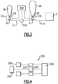
- FIG. 3 shows further schematic details of one system.
- a pitch change mechanism 40 allows the blades 24 to pivot about the axis 30.
- a pitch change mechanism 41 can change the pitch angle of the blades 28 about their respective axis 30.
- Pitch change mechanisms are known, and mechanisms 40/41 may be known.
- the pitch change of propeller systems in normal operation serves two functions. One is to allow for efficient conversion of power into thrust over a range of operating conditions including varying forward speeds by properly aligning the propeller blades with the incoming flow.
- the second is to allow the propeller system to control its speed of rotation.
- Figure 3 shows a drive input X driving a shaft portion 110 to, in turn, drive a shaft portion 111 through a clutch 109.
- the clutch 109 is shown as being controlled by a control 300.
- the control 300 further controls the pitch change mechanisms 40 and 41.
- the control 300 may open the clutch 109 stopping rotation of the hub 22 and blades 24.
- the angle of the blades 24 can still be changed by pitch change mechanism 40, such that the now stopped blades 24 can provide the function of guide vanes, as described below.
- the guide vane function is provided without the requirement of having a separate guide vane row.
- the use of such guide vanes becomes particularly valuable at lower power operation, and when it is not necessary to have both blade sets 24 and 28 to provide sufficient propulsion.
- the lower power operation could be cruise of the associated aircraft, and the higher power operation could be take-off of the associated aircraft.
- Allowing the stopped blade row to change pitch is intended to allow the blades to operate efficiently as guide vanes over a range of operating conditions including varying flight speeds.
- the vanes turn the swirling flow from the propeller in the axial direction converting some of the wasted energy in the swirling flow into thrust.
- the flow is swirled coming into the rotating row such that the flow exiting the rotating row is more predominantly in the axial direction, and thus generating more thrust, than it would have done without the guide vanes.
- a skilled worker in this art would recognize when a particular angle is desirable.
- FIG. 4 shows yet another embodiment, which is shown schematically.
- embodiment 200 has a first drive 202 for driving one hub 204.
- a second separate drive 206 drives the second hub 208.
- Both drives 202 and 206 are controlled by control 300.
- the control 300 may stop the drive 202 or 206, as appropriate, to stop rotation of the particular hub 204 or 208. This embodiment would operate as those described above.
- any number of mechanisms can be employed to stop drive of one of the blade sets. Those disclosed here are examples.
Landscapes
- Engineering & Computer Science (AREA)
- Aviation & Aerospace Engineering (AREA)
- Mechanical Engineering (AREA)
- Control Of Turbines (AREA)
- Structures Of Non-Positive Displacement Pumps (AREA)
- Transmission Devices (AREA)
Abstract
Description
- This application relates to counter-rotating propeller systems, such as for use on aircraft where one of the rows can be selectively stopped from rotating and its blades utilized as guide vanes during lower power operation.
- Propeller systems are known and often utilized to provide propulsion to aircraft. One known type of propeller system has two co-axial sets of rotating blades rotating with separate hubs. In many cases, the two sets of blades rotate in opposite directions. These are called counter-rotating propeller systems.
- It is also known to provide guide vanes either upstream or downstream of a propeller, which may have a variable angle of incidence, such as to redirect flow upstream or capture swirl downstream of the propeller blades. In at least one known system, there are dedicated guide vanes positioned downstream of the rotor and blades.
- A propeller system has a pair of rotors and a pair of blade sets and at least one drive input to drive a first of the rotors and blade sets and a second of the rotors and blade sets. The blade sets are positioned such that when both are driven, air will be driven across the first blade set and then across the second blade set. There is a pitch change mechanism to change an angle of incidence of the blade in at least one of the first and second blade sets. There is a device for selectively stopping rotation of the at least one of the first or second rotor and blade set while still allowing rotation of the other rotor and blade set. The pitch change mechanism of the stopped blade set can still change the angle of incidence when the device has stopped rotation.
- A method is also disclosed.
- These and other features may be best understood from the following drawings and specification.
-
-
Figure 1 schematically shows a propeller system. -
Figure 2 schematically shows a blade angle. -
Figure 3 schematically shows a first drive arrangement. -
Figure 4 schematically shows another alternative drive. -
Figure 1 shows apropeller system 20. An engine, such as aturbine engine 21, is illustrated schematically and driveshubs inlet 23 provides air to theturbine engine 21. Other drives could be utilized. A first set ofblades 24 rotates in one direction with aforward hub portion 22. A second set ofblades 28 rotates in the opposite direction with ahub portion 26. - Air is driven by
blades 24 and then acrossblades 28 which drive additional air flow. -
Figure 2 schematically shows a feature of theblades 28 and, namely, that an angle of incidence or pitch angle of the blades can change about apivot axis 30. In one embodiment, the same is true of theblades 24. In yet anotherembodiment blades 24 have a pitch change, butblades 28 do not. -
Figure 3 shows further schematic details of one system. Apitch change mechanism 40 allows theblades 24 to pivot about theaxis 30. - A
pitch change mechanism 41 can change the pitch angle of theblades 28 about theirrespective axis 30. - Pitch change mechanisms are known, and
mechanisms 40/41 may be known. - The pitch change of propeller systems in normal operation serves two functions. One is to allow for efficient conversion of power into thrust over a range of operating conditions including varying forward speeds by properly aligning the propeller blades with the incoming flow.
- The second is to allow the propeller system to control its speed of rotation.
-
Figure 3 shows a drive input X driving ashaft portion 110 to, in turn, drive ashaft portion 111 through aclutch 109. - The
clutch 109 is shown as being controlled by acontrol 300. Thecontrol 300 further controls thepitch change mechanisms - Now, at lower power operation, the
control 300 may open theclutch 109 stopping rotation of thehub 22 andblades 24. The angle of theblades 24 can still be changed bypitch change mechanism 40, such that the now stoppedblades 24 can provide the function of guide vanes, as described below. Thus, the guide vane function is provided without the requirement of having a separate guide vane row. The use of such guide vanes becomes particularly valuable at lower power operation, and when it is not necessary to have bothblade sets - Allowing the stopped blade row to change pitch is intended to allow the blades to operate efficiently as guide vanes over a range of operating conditions including varying flight speeds. In the case where the guide vanes are aft of the rotating row, the vanes turn the swirling flow from the propeller in the axial direction converting some of the wasted energy in the swirling flow into thrust. Similarly, in the situation where the guide vanes are in front of the rotating blade row, the flow is swirled coming into the rotating row such that the flow exiting the rotating row is more predominantly in the axial direction, and thus generating more thrust, than it would have done without the guide vanes. A skilled worker in this art would recognize when a particular angle is desirable.
- In another embodiment, a clutch could be positioned to stop the rotation of the
hub 26 andblades 28 which would then serve as guide vanes for the flow exiting the rotating front blade set 24.Figure 4 shows yet another embodiment, which is shown schematically. Here,embodiment 200 has afirst drive 202 for driving onehub 204. A secondseparate drive 206 drives thesecond hub 208. Bothdrives control 300. In this embodiment, thecontrol 300 may stop thedrive particular hub - As can be appreciated, any number of mechanisms can be employed to stop drive of one of the blade sets. Those disclosed here are examples.
- Although embodiments have been disclosed, a worker of ordinary skill in this art would recognize that certain modifications would come within the scope of this disclosure. For that reason, the following claims should be studied to determine the true scope and content of this disclosure.
Claims (15)
- A propeller system comprising:a pair of rotors and a pair of blade sets (24, 28) and at least one drive input to drive a first of said rotors and blade sets and a second of said rotors and blade sets;said blade sets (24, 28) being positioned such that when both are driven, air will be driven across said first blade set (24), and then across said second blade set (28);there being a pitch change mechanism (40, 41) to change an angle of incidence in at least one of said first and second blade sets (24, 28), and there being a device for selectively stopping rotation of said at least one of said first and second blade sets (24, 28) while still allowing rotation of the other of said first and second blade sets (24, 28); andsaid pitch change mechanism (40, 41) of said at least one of said first and second blade sets (24, 28) still allowing change of said angle of incidence when said device has stopped rotation.
- The propeller system as set forth in claim 1, wherein said at least one drive input is a single drive input.
- The propeller system as set forth in claim 2, wherein said device is a clutch (109).
- The propeller system as set forth in any of claims 1-3, wherein a control (300) selectively changes the angle of incidence of said one of said first and second blade sets (24, 28) and also selectively controls said device.
- The propeller system as set forth in any preceding claim, said control (300) causing said one of said first and second blade sets (24, 28) to be driven when at higher power operation of an associated aircraft, and stopping rotation of said one of said first and second blade sets (24, 28) at lower power operation of said aircraft, and preferably wherein said higher power operation includes a take-off condition for the associated aircraft, and more preferably wherein said lower power operation includes a cruise condition of the associated aircraft.
- The propeller system as set forth in any preceding claim, wherein said device is a clutch (109) for stopping rotation of said one of said first and second blade sets (24, 28).
- The propeller system as set forth in any preceding claim, wherein said at least one drive input to said first and second rotors and blade sets (24, 28) are two separate drive inputs, and said device is a control for stopping drive input from a respective one of said first and second drive inputs, and preferably wherein a control (300) causes said one of said first and second blade sets to be driven at higher power operation of an associated aircraft, and stops rotation of said one of said first and second blade sets (24, 28) at lower power operation of said aircraft.
- A method of operating a propeller system mounted on an aircraft comprising the steps of:(a) providing a pair of rotors and a pair of blade sets and driving a first of said rotors and blade sets and a second of said rotors and blade sets; and(b) stopping rotation of one of said first and second blade sets, while still rotating a second of said first and second blade sets, and changing an angle of incidence of said one of said first and second blade sets while it is stopped from rotating.
- The propeller system as set forth in claim 8, wherein a control selectively changing the angle of incidence of one of said first and second blade sets and also selectively controlling a device to stop rotation of said at least one of said first and second blade sets.
- The propeller system as set forth in claim 9, wherein said control causing said one of said first and second blade sets to be driven at higher power operation of an associated aircraft, and stopping rotation of said one of said first and second blade sets at lower power operations.
- The propeller system as set forth in claim 10, wherein said higher power operation includes a take-off condition for the associated aircraft.
- The propeller system as set forth in claim 11, wherein said lower power operation includes a cruise condition of the associated aircraft.
- The propeller system as set forth in claim 11, wherein a control causing said one of said first and second blade sets to be driven at higher power operation of an associated aircraft, and stopping rotation of said one of said first and second blade sets at lower power operations, and preferably wherein said higher power operation includes a take-off condition for the associated aircraft.
- The propeller system as set forth in any of claims 11-13, wherein a clutch is opened for stopping rotation of said one of said first and second blade sets.
- The propeller system as set forth in any of claims 11-14, wherein said drive to said first and second rotors and blade sets is provided by two separate drive inputs, and a control stopping drive input from a respective one of said two drive inputs.
Applications Claiming Priority (1)
| Application Number | Priority Date | Filing Date | Title |
|---|---|---|---|
| US15/924,030 US20190283864A1 (en) | 2018-03-16 | 2018-03-16 | Counter-rotating propeller system with capability to stop rotation of one row |
Publications (2)
| Publication Number | Publication Date |
|---|---|
| EP3539866A1 true EP3539866A1 (en) | 2019-09-18 |
| EP3539866B1 EP3539866B1 (en) | 2023-04-26 |
Family
ID=65818346
Family Applications (1)
| Application Number | Title | Priority Date | Filing Date |
|---|---|---|---|
| EP19163472.4A Active EP3539866B1 (en) | 2018-03-16 | 2019-03-18 | Counter-rotating propeller system with capability to stop rotation of one row |
Country Status (4)
| Country | Link |
|---|---|
| US (1) | US20190283864A1 (en) |
| EP (1) | EP3539866B1 (en) |
| CN (1) | CN110271682B (en) |
| CA (1) | CA3036856A1 (en) |
Families Citing this family (5)
| Publication number | Priority date | Publication date | Assignee | Title |
|---|---|---|---|---|
| US11738862B2 (en) * | 2020-01-28 | 2023-08-29 | Overair, Inc. | Fail-operational vtol aircraft |
| EP4269240B1 (en) * | 2020-12-22 | 2025-02-26 | Panasonic Intellectual Property Management Co., Ltd. | Motor unit and flying object |
| US12565328B2 (en) | 2024-07-15 | 2026-03-03 | Rtx Corporation | Differential driven open rotor with brake |
| US20260092556A1 (en) * | 2024-10-01 | 2026-04-02 | Rtx Corporation | Open rotor propulsion system with forward exhaust outlet(s) |
| US20260104019A1 (en) * | 2024-10-11 | 2026-04-16 | Rtx Corporation | Aircraft propulsion system with selectively rotatable open propulsor rotor |
Citations (4)
| Publication number | Priority date | Publication date | Assignee | Title |
|---|---|---|---|---|
| US20120000177A1 (en) * | 2010-07-05 | 2012-01-05 | Snecma | Turbine engine with nonstreamlined impellers |
| US20150104309A1 (en) * | 2013-10-16 | 2015-04-16 | Hamilton Sundstrand Corporation | Aircraft control system and method |
| EP2907747A1 (en) * | 2014-02-12 | 2015-08-19 | Hamilton Sundstrand Corporation | Cyclic pitch actuation system for counter-rotating propellers |
| US20170313430A1 (en) * | 2016-04-28 | 2017-11-02 | Airbus Operations Sas | Aircraft engine assembly comprising a pylon leading edge incorporated with an annular row of unfaired after-guide vanes |
Family Cites Families (18)
| Publication number | Priority date | Publication date | Assignee | Title |
|---|---|---|---|---|
| FR862210A (en) * | 1939-02-16 | 1941-03-01 | Pitch variation mechanism for propellers | |
| US2312624A (en) * | 1939-12-30 | 1943-03-02 | United Aircraft Corp | Counterrotating propeller |
| US2380889A (en) * | 1941-07-26 | 1945-07-31 | Waseige Charles Raymond | Polyengine bipropeller drive |
| US2389161A (en) * | 1942-09-11 | 1945-11-20 | Howard M Mccoy | Controllable pitch change mechanism for dual rotation propellers |
| US2826255A (en) * | 1951-06-14 | 1958-03-11 | Gen Motors Corp | Propeller drives |
| US3957229A (en) * | 1973-08-09 | 1976-05-18 | Davis Harry C | Convertible auxiliary turbine for aircraft |
| DE3347679C2 (en) * | 1983-12-31 | 1985-11-14 | Sita Bauelemente Gmbh, 2080 Pinneberg | Double propeller |
| US4642029A (en) * | 1985-06-17 | 1987-02-10 | General Motors Corporation | Brake for counter rotating bladed members |
| US5242265A (en) * | 1990-07-23 | 1993-09-07 | General Electric Company | Aircraft pitch change mechanism |
| US5954479A (en) * | 1996-12-16 | 1999-09-21 | Smith; Ronald A. | Twin engine, coaxial, dual-propeller propulsion system |
| US6761144B2 (en) * | 2002-05-17 | 2004-07-13 | Paul A. Schwam | Rotary engine with counter-rotating housing and output shaft mounted on stationary spindle |
| WO2005049423A2 (en) * | 2003-11-18 | 2005-06-02 | Distributed Thermal Systems Ltd. | Coaxial propulsion systems with flow modification element |
| US8661781B2 (en) * | 2009-02-13 | 2014-03-04 | The Boeing Company | Counter rotating fan design and variable blade row spacing optimization for low environmental impact |
| FR2964948B1 (en) * | 2010-09-16 | 2012-08-31 | Eurocopter France | ROTARY VESSEL AIRCRAFT WITH A PROPULSIVE MEANS AND METHOD APPLIED THERETO |
| US8955335B2 (en) * | 2010-12-30 | 2015-02-17 | Rolls-Royce Corporation | System, propulsion system and vehicle |
| US9835093B2 (en) * | 2013-09-19 | 2017-12-05 | The Boeing Company | Contra-rotating open fan propulsion system |
| CN203698651U (en) * | 2013-12-13 | 2014-07-09 | 左承龙 | Variable pitch propeller of fixed wing aircraft |
| US10752352B2 (en) * | 2017-12-07 | 2020-08-25 | Textron Innovations Inc. | Dual rotor propulsion systems for tiltrotor aircraft |
-
2018
- 2018-03-16 US US15/924,030 patent/US20190283864A1/en not_active Abandoned
-
2019
- 2019-03-15 CA CA3036856A patent/CA3036856A1/en active Pending
- 2019-03-15 CN CN201910197566.0A patent/CN110271682B/en active Active
- 2019-03-18 EP EP19163472.4A patent/EP3539866B1/en active Active
Patent Citations (4)
| Publication number | Priority date | Publication date | Assignee | Title |
|---|---|---|---|---|
| US20120000177A1 (en) * | 2010-07-05 | 2012-01-05 | Snecma | Turbine engine with nonstreamlined impellers |
| US20150104309A1 (en) * | 2013-10-16 | 2015-04-16 | Hamilton Sundstrand Corporation | Aircraft control system and method |
| EP2907747A1 (en) * | 2014-02-12 | 2015-08-19 | Hamilton Sundstrand Corporation | Cyclic pitch actuation system for counter-rotating propellers |
| US20170313430A1 (en) * | 2016-04-28 | 2017-11-02 | Airbus Operations Sas | Aircraft engine assembly comprising a pylon leading edge incorporated with an annular row of unfaired after-guide vanes |
Also Published As
| Publication number | Publication date |
|---|---|
| BR102019003313A2 (en) | 2019-10-29 |
| CN110271682B (en) | 2023-12-08 |
| EP3539866B1 (en) | 2023-04-26 |
| US20190283864A1 (en) | 2019-09-19 |
| CN110271682A (en) | 2019-09-24 |
| CA3036856A1 (en) | 2019-09-16 |
Similar Documents
| Publication | Publication Date | Title |
|---|---|---|
| EP3653859B1 (en) | Multi-engine system and method | |
| EP3539866B1 (en) | Counter-rotating propeller system with capability to stop rotation of one row | |
| US5054998A (en) | Thrust reversing system for counter rotating propellers | |
| US11230385B2 (en) | Hybrid-electric propulsion system for an aircraft | |
| US20130104522A1 (en) | Gas turbine engine with variable pitch first stage fan section | |
| EP2540989B1 (en) | Variable cycle turbine engine | |
| US7395988B2 (en) | Rotor wing aircraft having an adjustable tail nozzle | |
| EP2163730B1 (en) | Method and system for controlling propeller overspeed | |
| US10316857B2 (en) | Variable-pitch fan with low pitch of a turbine engine | |
| US20070130913A1 (en) | Coaxial propulsion systems with flow modification element | |
| EP2902608B1 (en) | Aft shrouded geared turbofan | |
| EP4279708B1 (en) | Gas turbine engine | |
| US20070095969A1 (en) | Rotor wing aircraft having a bypassable radial inflow turbine | |
| EP3839227B1 (en) | Gas turbine engine with variable speed output | |
| US12044182B2 (en) | Shaft power transfer for a multi spool gas turbine engine | |
| US10830066B2 (en) | Low-pitch variable-setting fan of a turbine engine | |
| EP4123149A1 (en) | Gas turbine engine with low-pressure compressor bypass | |
| BR102019003313B1 (en) | PROPELLER SYSTEM, AND, METHOD OF OPERATING A PROPELLER SYSTEM | |
| US3279546A (en) | Rotor-tip-mounted propulsion system for helicopters | |
| NO129700B (en) |
Legal Events
| Date | Code | Title | Description |
|---|---|---|---|
| PUAI | Public reference made under article 153(3) epc to a published international application that has entered the european phase |
Free format text: ORIGINAL CODE: 0009012 |
|
| STAA | Information on the status of an ep patent application or granted ep patent |
Free format text: STATUS: THE APPLICATION HAS BEEN PUBLISHED |
|
| AK | Designated contracting states |
Kind code of ref document: A1 Designated state(s): AL AT BE BG CH CY CZ DE DK EE ES FI FR GB GR HR HU IE IS IT LI LT LU LV MC MK MT NL NO PL PT RO RS SE SI SK SM TR |
|
| AX | Request for extension of the european patent |
Extension state: BA ME |
|
| STAA | Information on the status of an ep patent application or granted ep patent |
Free format text: STATUS: REQUEST FOR EXAMINATION WAS MADE |
|
| 17P | Request for examination filed |
Effective date: 20200313 |
|
| RBV | Designated contracting states (corrected) |
Designated state(s): AL AT BE BG CH CY CZ DE DK EE ES FI FR GB GR HR HU IE IS IT LI LT LU LV MC MK MT NL NO PL PT RO RS SE SI SK SM TR |
|
| STAA | Information on the status of an ep patent application or granted ep patent |
Free format text: STATUS: EXAMINATION IS IN PROGRESS |
|
| 17Q | First examination report despatched |
Effective date: 20201013 |
|
| REG | Reference to a national code |
Ref country code: DE Ref legal event code: R079 Ref document number: 602019027941 Country of ref document: DE Free format text: PREVIOUS MAIN CLASS: B64C0011480000 Ipc: B64C0011300000 |
|
| RIC1 | Information provided on ipc code assigned before grant |
Ipc: B64D 27/00 20060101ALN20220930BHEP Ipc: B64D 27/10 20060101ALN20220930BHEP Ipc: B64C 11/48 20060101ALI20220930BHEP Ipc: B64D 35/06 20060101ALI20220930BHEP Ipc: B64D 35/04 20060101ALI20220930BHEP Ipc: B64C 11/30 20060101AFI20220930BHEP |
|
| GRAP | Despatch of communication of intention to grant a patent |
Free format text: ORIGINAL CODE: EPIDOSNIGR1 |
|
| STAA | Information on the status of an ep patent application or granted ep patent |
Free format text: STATUS: GRANT OF PATENT IS INTENDED |
|
| RIC1 | Information provided on ipc code assigned before grant |
Ipc: B64D 27/00 20060101ALN20221019BHEP Ipc: B64D 27/10 20060101ALN20221019BHEP Ipc: B64C 11/48 20060101ALI20221019BHEP Ipc: B64D 35/06 20060101ALI20221019BHEP Ipc: B64D 35/04 20060101ALI20221019BHEP Ipc: B64C 11/30 20060101AFI20221019BHEP |
|
| RIC1 | Information provided on ipc code assigned before grant |
Ipc: B64D 27/00 20060101ALN20221102BHEP Ipc: B64D 27/10 20060101ALN20221102BHEP Ipc: B64C 11/48 20060101ALI20221102BHEP Ipc: B64D 35/06 20060101ALI20221102BHEP Ipc: B64D 35/04 20060101ALI20221102BHEP Ipc: B64C 11/30 20060101AFI20221102BHEP |
|
| INTG | Intention to grant announced |
Effective date: 20221122 |
|
| GRAS | Grant fee paid |
Free format text: ORIGINAL CODE: EPIDOSNIGR3 |
|
| GRAA | (expected) grant |
Free format text: ORIGINAL CODE: 0009210 |
|
| STAA | Information on the status of an ep patent application or granted ep patent |
Free format text: STATUS: THE PATENT HAS BEEN GRANTED |
|
| AK | Designated contracting states |
Kind code of ref document: B1 Designated state(s): AL AT BE BG CH CY CZ DE DK EE ES FI FR GB GR HR HU IE IS IT LI LT LU LV MC MK MT NL NO PL PT RO RS SE SI SK SM TR |
|
| REG | Reference to a national code |
Ref country code: GB Ref legal event code: FG4D |
|
| REG | Reference to a national code |
Ref country code: CH Ref legal event code: EP |
|
| REG | Reference to a national code |
Ref country code: DE Ref legal event code: R096 Ref document number: 602019027941 Country of ref document: DE |
|
| REG | Reference to a national code |
Ref country code: AT Ref legal event code: REF Ref document number: 1562653 Country of ref document: AT Kind code of ref document: T Effective date: 20230515 |
|
| REG | Reference to a national code |
Ref country code: IE Ref legal event code: FG4D |
|
| REG | Reference to a national code |
Ref country code: LT Ref legal event code: MG9D |
|
| REG | Reference to a national code |
Ref country code: NL Ref legal event code: MP Effective date: 20230426 |
|
| REG | Reference to a national code |
Ref country code: AT Ref legal event code: MK05 Ref document number: 1562653 Country of ref document: AT Kind code of ref document: T Effective date: 20230426 |
|
| PG25 | Lapsed in a contracting state [announced via postgrant information from national office to epo] |
Ref country code: NL Free format text: LAPSE BECAUSE OF FAILURE TO SUBMIT A TRANSLATION OF THE DESCRIPTION OR TO PAY THE FEE WITHIN THE PRESCRIBED TIME-LIMIT Effective date: 20230426 |
|
| PG25 | Lapsed in a contracting state [announced via postgrant information from national office to epo] |
Ref country code: SE Free format text: LAPSE BECAUSE OF FAILURE TO SUBMIT A TRANSLATION OF THE DESCRIPTION OR TO PAY THE FEE WITHIN THE PRESCRIBED TIME-LIMIT Effective date: 20230426 Ref country code: PT Free format text: LAPSE BECAUSE OF FAILURE TO SUBMIT A TRANSLATION OF THE DESCRIPTION OR TO PAY THE FEE WITHIN THE PRESCRIBED TIME-LIMIT Effective date: 20230828 Ref country code: NO Free format text: LAPSE BECAUSE OF FAILURE TO SUBMIT A TRANSLATION OF THE DESCRIPTION OR TO PAY THE FEE WITHIN THE PRESCRIBED TIME-LIMIT Effective date: 20230726 Ref country code: ES Free format text: LAPSE BECAUSE OF FAILURE TO SUBMIT A TRANSLATION OF THE DESCRIPTION OR TO PAY THE FEE WITHIN THE PRESCRIBED TIME-LIMIT Effective date: 20230426 Ref country code: AT Free format text: LAPSE BECAUSE OF FAILURE TO SUBMIT A TRANSLATION OF THE DESCRIPTION OR TO PAY THE FEE WITHIN THE PRESCRIBED TIME-LIMIT Effective date: 20230426 |
|
| PG25 | Lapsed in a contracting state [announced via postgrant information from national office to epo] |
Ref country code: RS Free format text: LAPSE BECAUSE OF FAILURE TO SUBMIT A TRANSLATION OF THE DESCRIPTION OR TO PAY THE FEE WITHIN THE PRESCRIBED TIME-LIMIT Effective date: 20230426 Ref country code: PL Free format text: LAPSE BECAUSE OF FAILURE TO SUBMIT A TRANSLATION OF THE DESCRIPTION OR TO PAY THE FEE WITHIN THE PRESCRIBED TIME-LIMIT Effective date: 20230426 Ref country code: LV Free format text: LAPSE BECAUSE OF FAILURE TO SUBMIT A TRANSLATION OF THE DESCRIPTION OR TO PAY THE FEE WITHIN THE PRESCRIBED TIME-LIMIT Effective date: 20230426 Ref country code: LT Free format text: LAPSE BECAUSE OF FAILURE TO SUBMIT A TRANSLATION OF THE DESCRIPTION OR TO PAY THE FEE WITHIN THE PRESCRIBED TIME-LIMIT Effective date: 20230426 Ref country code: IS Free format text: LAPSE BECAUSE OF FAILURE TO SUBMIT A TRANSLATION OF THE DESCRIPTION OR TO PAY THE FEE WITHIN THE PRESCRIBED TIME-LIMIT Effective date: 20230826 Ref country code: HR Free format text: LAPSE BECAUSE OF FAILURE TO SUBMIT A TRANSLATION OF THE DESCRIPTION OR TO PAY THE FEE WITHIN THE PRESCRIBED TIME-LIMIT Effective date: 20230426 Ref country code: GR Free format text: LAPSE BECAUSE OF FAILURE TO SUBMIT A TRANSLATION OF THE DESCRIPTION OR TO PAY THE FEE WITHIN THE PRESCRIBED TIME-LIMIT Effective date: 20230727 |
|
| PG25 | Lapsed in a contracting state [announced via postgrant information from national office to epo] |
Ref country code: FI Free format text: LAPSE BECAUSE OF FAILURE TO SUBMIT A TRANSLATION OF THE DESCRIPTION OR TO PAY THE FEE WITHIN THE PRESCRIBED TIME-LIMIT Effective date: 20230426 |
|
| PG25 | Lapsed in a contracting state [announced via postgrant information from national office to epo] |
Ref country code: SK Free format text: LAPSE BECAUSE OF FAILURE TO SUBMIT A TRANSLATION OF THE DESCRIPTION OR TO PAY THE FEE WITHIN THE PRESCRIBED TIME-LIMIT Effective date: 20230426 |
|
| REG | Reference to a national code |
Ref country code: DE Ref legal event code: R097 Ref document number: 602019027941 Country of ref document: DE |
|
| PG25 | Lapsed in a contracting state [announced via postgrant information from national office to epo] |
Ref country code: SM Free format text: LAPSE BECAUSE OF FAILURE TO SUBMIT A TRANSLATION OF THE DESCRIPTION OR TO PAY THE FEE WITHIN THE PRESCRIBED TIME-LIMIT Effective date: 20230426 Ref country code: SK Free format text: LAPSE BECAUSE OF FAILURE TO SUBMIT A TRANSLATION OF THE DESCRIPTION OR TO PAY THE FEE WITHIN THE PRESCRIBED TIME-LIMIT Effective date: 20230426 Ref country code: RO Free format text: LAPSE BECAUSE OF FAILURE TO SUBMIT A TRANSLATION OF THE DESCRIPTION OR TO PAY THE FEE WITHIN THE PRESCRIBED TIME-LIMIT Effective date: 20230426 Ref country code: EE Free format text: LAPSE BECAUSE OF FAILURE TO SUBMIT A TRANSLATION OF THE DESCRIPTION OR TO PAY THE FEE WITHIN THE PRESCRIBED TIME-LIMIT Effective date: 20230426 Ref country code: DK Free format text: LAPSE BECAUSE OF FAILURE TO SUBMIT A TRANSLATION OF THE DESCRIPTION OR TO PAY THE FEE WITHIN THE PRESCRIBED TIME-LIMIT Effective date: 20230426 Ref country code: CZ Free format text: LAPSE BECAUSE OF FAILURE TO SUBMIT A TRANSLATION OF THE DESCRIPTION OR TO PAY THE FEE WITHIN THE PRESCRIBED TIME-LIMIT Effective date: 20230426 |
|
| PLBE | No opposition filed within time limit |
Free format text: ORIGINAL CODE: 0009261 |
|
| STAA | Information on the status of an ep patent application or granted ep patent |
Free format text: STATUS: NO OPPOSITION FILED WITHIN TIME LIMIT |
|
| 26N | No opposition filed |
Effective date: 20240129 |
|
| PG25 | Lapsed in a contracting state [announced via postgrant information from national office to epo] |
Ref country code: SI Free format text: LAPSE BECAUSE OF FAILURE TO SUBMIT A TRANSLATION OF THE DESCRIPTION OR TO PAY THE FEE WITHIN THE PRESCRIBED TIME-LIMIT Effective date: 20230426 |
|
| PG25 | Lapsed in a contracting state [announced via postgrant information from national office to epo] |
Ref country code: SI Free format text: LAPSE BECAUSE OF FAILURE TO SUBMIT A TRANSLATION OF THE DESCRIPTION OR TO PAY THE FEE WITHIN THE PRESCRIBED TIME-LIMIT Effective date: 20230426 |
|
| REG | Reference to a national code |
Ref country code: CH Ref legal event code: PL |
|
| PG25 | Lapsed in a contracting state [announced via postgrant information from national office to epo] |
Ref country code: BG Free format text: LAPSE BECAUSE OF FAILURE TO SUBMIT A TRANSLATION OF THE DESCRIPTION OR TO PAY THE FEE WITHIN THE PRESCRIBED TIME-LIMIT Effective date: 20230426 |
|
| PG25 | Lapsed in a contracting state [announced via postgrant information from national office to epo] |
Ref country code: LU Free format text: LAPSE BECAUSE OF NON-PAYMENT OF DUE FEES Effective date: 20240318 |
|
| PG25 | Lapsed in a contracting state [announced via postgrant information from national office to epo] |
Ref country code: MC Free format text: LAPSE BECAUSE OF FAILURE TO SUBMIT A TRANSLATION OF THE DESCRIPTION OR TO PAY THE FEE WITHIN THE PRESCRIBED TIME-LIMIT Effective date: 20230426 |
|
| PG25 | Lapsed in a contracting state [announced via postgrant information from national office to epo] |
Ref country code: MC Free format text: LAPSE BECAUSE OF FAILURE TO SUBMIT A TRANSLATION OF THE DESCRIPTION OR TO PAY THE FEE WITHIN THE PRESCRIBED TIME-LIMIT Effective date: 20230426 Ref country code: LU Free format text: LAPSE BECAUSE OF NON-PAYMENT OF DUE FEES Effective date: 20240318 Ref country code: BG Free format text: LAPSE BECAUSE OF FAILURE TO SUBMIT A TRANSLATION OF THE DESCRIPTION OR TO PAY THE FEE WITHIN THE PRESCRIBED TIME-LIMIT Effective date: 20230426 |
|
| REG | Reference to a national code |
Ref country code: BE Ref legal event code: MM Effective date: 20240331 |
|
| PG25 | Lapsed in a contracting state [announced via postgrant information from national office to epo] |
Ref country code: BE Free format text: LAPSE BECAUSE OF NON-PAYMENT OF DUE FEES Effective date: 20240331 |
|
| PG25 | Lapsed in a contracting state [announced via postgrant information from national office to epo] |
Ref country code: IE Free format text: LAPSE BECAUSE OF NON-PAYMENT OF DUE FEES Effective date: 20240318 |
|
| PG25 | Lapsed in a contracting state [announced via postgrant information from national office to epo] |
Ref country code: IE Free format text: LAPSE BECAUSE OF NON-PAYMENT OF DUE FEES Effective date: 20240318 Ref country code: BE Free format text: LAPSE BECAUSE OF NON-PAYMENT OF DUE FEES Effective date: 20240331 Ref country code: CH Free format text: LAPSE BECAUSE OF NON-PAYMENT OF DUE FEES Effective date: 20240331 |
|
| PG25 | Lapsed in a contracting state [announced via postgrant information from national office to epo] |
Ref country code: CY Free format text: LAPSE BECAUSE OF FAILURE TO SUBMIT A TRANSLATION OF THE DESCRIPTION OR TO PAY THE FEE WITHIN THE PRESCRIBED TIME-LIMIT; INVALID AB INITIO Effective date: 20190318 |
|
| PG25 | Lapsed in a contracting state [announced via postgrant information from national office to epo] |
Ref country code: HU Free format text: LAPSE BECAUSE OF FAILURE TO SUBMIT A TRANSLATION OF THE DESCRIPTION OR TO PAY THE FEE WITHIN THE PRESCRIBED TIME-LIMIT; INVALID AB INITIO Effective date: 20190318 |
|
| PG25 | Lapsed in a contracting state [announced via postgrant information from national office to epo] |
Ref country code: TR Free format text: LAPSE BECAUSE OF FAILURE TO SUBMIT A TRANSLATION OF THE DESCRIPTION OR TO PAY THE FEE WITHIN THE PRESCRIBED TIME-LIMIT Effective date: 20230426 |
|
| P01 | Opt-out of the competence of the unified patent court (upc) registered |
Free format text: CASE NUMBER: UPC_APP_0017959_3539866/2025 Effective date: 20251217 |
|
| PGFP | Annual fee paid to national office [announced via postgrant information from national office to epo] |
Ref country code: GB Payment date: 20260219 Year of fee payment: 8 |
|
| PGFP | Annual fee paid to national office [announced via postgrant information from national office to epo] |
Ref country code: DE Payment date: 20260219 Year of fee payment: 8 |
|
| PGFP | Annual fee paid to national office [announced via postgrant information from national office to epo] |
Ref country code: IT Payment date: 20260219 Year of fee payment: 8 |
|
| PGFP | Annual fee paid to national office [announced via postgrant information from national office to epo] |
Ref country code: FR Payment date: 20260219 Year of fee payment: 8 |