EP3539861A1 - Small boat - Google Patents
Small boat Download PDFInfo
- Publication number
- EP3539861A1 EP3539861A1 EP19161786.9A EP19161786A EP3539861A1 EP 3539861 A1 EP3539861 A1 EP 3539861A1 EP 19161786 A EP19161786 A EP 19161786A EP 3539861 A1 EP3539861 A1 EP 3539861A1
- Authority
- EP
- European Patent Office
- Prior art keywords
- output
- operation amount
- signal
- maximum
- voltage value
- Prior art date
- Legal status (The legal status is an assumption and is not a legal conclusion. Google has not performed a legal analysis and makes no representation as to the accuracy of the status listed.)
- Granted
Links
Images




Classifications
-
- G—PHYSICS
- G05—CONTROLLING; REGULATING
- G05G—CONTROL DEVICES OR SYSTEMS INSOFAR AS CHARACTERISED BY MECHANICAL FEATURES ONLY
- G05G1/00—Controlling members, e.g. knobs or handles; Assemblies or arrangements thereof; Indicating position of controlling members
- G05G1/04—Controlling members for hand actuation by pivoting movement, e.g. levers
-
- B—PERFORMING OPERATIONS; TRANSPORTING
- B63—SHIPS OR OTHER WATERBORNE VESSELS; RELATED EQUIPMENT
- B63H—MARINE PROPULSION OR STEERING
- B63H21/00—Use of propulsion power plant or units on vessels
- B63H21/21—Control means for engine or transmission, specially adapted for use on marine vessels
- B63H21/213—Levers or the like for controlling the engine or the transmission, e.g. single hand control levers
-
- B—PERFORMING OPERATIONS; TRANSPORTING
- B63—SHIPS OR OTHER WATERBORNE VESSELS; RELATED EQUIPMENT
- B63B—SHIPS OR OTHER WATERBORNE VESSELS; EQUIPMENT FOR SHIPPING
- B63B34/00—Vessels specially adapted for water sports or leisure; Body-supporting devices specially adapted for water sports or leisure
- B63B34/10—Power-driven personal watercraft, e.g. water scooters; Accessories therefor
Definitions
- the present invention relates to a small boat.
- a throttle operating device (a small boat) including a throttle operator is known in general.
- Such a throttle operating device (a small boat) is disclosed in Japanese Patent No. 5543224 , for example.
- Japanese Patent No. 5543224 discloses a lever-type throttle operating device (hereinafter referred to as a "throttle operating device”) including a throttle lever.
- the throttle operating device includes an angle sensor that detects the rotational operation angle of the throttle lever and a board that acquires a detection signal from the angle sensor and outputs an output signal.
- the board outputs the output signal to an engine control unit (hereinafter referred to as an "ECU") via a wiring cord.
- the ECU controls driving of an engine based on the acquired output signal (detection signal).
- horsepower regulations or output regulations may be implemented by varying the upper limit of horsepower based on the license acquired by a boat operator who operates the small boat and the age of the boat operator.
- the upper limit of the output value of the output signal output from the throttle operating device may be conceivably limited by mechanically limiting the movable range of the throttle lever.
- the throttle lever may conceivably include a stopper that mechanically limits the movable range of the throttle lever.
- a small boat includes a throttle operator through which a throttle opening degree of an engine is controlled, an engine controller that is configured to control the throttle opening degree, and an forward signal output that is configured to output, to the engine controller, an output signal having an output value at which the throttle opening degree increases as an operation amount of the throttle operator increases, and is configured to output, to the engine controller, the output signal having, as an upper limit, a limit output value at which the throttle opening degree becomes smaller than that at a maximum output voltage value at which the throttle opening degree becomes maximum.
- the forward signal output is configured to output, to the engine controller, the output signal having, as an upper limit, the limit output value at which the throttle opening degree becomes smaller than that at the maximum output value at which the throttle opening degree becomes maximum. Accordingly, the horsepower of the small boat (engine) is limited to an amount corresponding to the limit output value without limiting the upper limit of the operation amount of the throttle operator (without mechanically limiting the movable range). Consequently, unlike the case in which the movable range of the throttle operator is mechanically limited, no error is caused due to the structure that limits the movable range, and thus the upper limit of the output signal is more accurately limited.
- the horsepower is more accurately limited as compared with the case in which the movable range of the throttle operator is mechanically limited.
- the horsepower corresponding to the limit output value the amount of horsepower limited by laws and regulations, for example
- the horsepower of the engine of the small boat is limited to an amount corresponding to the limit output value.
- the small boat complies with horsepower regulations while an increase in the number of engine types is significantly reduce or prevented.
- the horsepower is limited by the engine controller (ECU)
- the control program of the engine controller for each limited horsepower, and when the control program is changed, an inspection to operate the engine controller is required for each small boat.
- the forward signal output is configured to output the output signal having the limit output value as an upper limit to the engine controller such that the horsepower of the small boat is limited by changing (replacing) the output (throttle operating device, for example) without changing the control program of the engine controller.
- the small boat complies with horsepower regulations while the number of inspection steps of the engine controller that operates the entire small boat is reduced as compared with the case in which the control program of the engine controller (ECU) is changed.
- the forward signal output is configured to output the output signal having the limit output value to the engine controller when the operation amount is a maximum operation amount. Accordingly, even when the throttle operator is operated to the maximum operation amount (when the operation amount of the throttle operator is not limited), the output signal having the limit output value as an upper limit is output, and thus the small boat complies with horsepower regulations without changing the range (movable range) of the operation amount of the throttle operator.
- the forward signal output is configured to output the output signal having the limit output value to the engine controller when the operation amount is equal to or larger than an operation amount threshold that is smaller than the maximum operation amount. Accordingly, output of the output signal that exceeds the limit output value is prevented even when the throttle operator is operated to the operation amount equal to or larger than the predetermined operation amount threshold.
- the forward signal output is configured to output, to the engine controller, the output signal having the output value at which the throttle opening degree increases as the operation amount increases over a range from the operation amount of 0 to the maximum operation amount. Accordingly, the output value corresponding to the operation amount is output (the throttle opening degree is adjusted) over the range from the operation amount of 0 to the maximum operation amount while the upper limit of the output value is limited to the limit output value, and thus while the small boat complies with horsepower regulations, the output value is more precisely adjusted as compared with the case in which the output signal having the limit output value (constant value) at the operation amount equal to or larger than the operation amount threshold is output.
- the forward signal output is configured to output, to the engine controller, the output signal having the output value at which the throttle opening degree increases as the operation amount increases such that the operation amount and the output value have a linear function relationship over the range from the operation amount of 0 to the maximum operation amount. Accordingly, even when the upper limit of the output value is limited to the limit output value, a boat operator more intuitively adjusts the output value as compared with the case in which the operation amount and the output value have a relatively complicated relationship (output characteristics) other than the linear function.
- the throttle operator is preferably rotationally operated
- the small boat preferably further includes an angle detector that is configured to detect a rotation angle of the throttle operator, and the forward signal output is configured to output the output signal having the limit output value, assuming that the operation amount is the maximum operation amount, to the engine controller when the rotation angle that is detected by the angle detector is a maximum angle. Accordingly, the upper limit of the output value of the output signal is limited to the limit output value without limiting the rotation angle of the throttle operator to an angle smaller than the maximum angle (without changing the movable range).
- the throttle operator preferably extends from a rotation shaft disposed in a vicinity of a grip grasped by a boat operator in a radial direction of the rotation shaft, and is preferably a lever that is configured to be rotated about the rotation shaft toward the grip
- the angle detector preferably faces the rotation shaft in the radial direction, and is configured to detect a rotation angle of the rotation shaft as the operation amount
- the forward signal output is configured to output the output signal having the limit output value, assuming that the operation amount is the maximum operation amount, to the engine controller when the rotation angle that is detected by the angle detector is the maximum angle.
- a small boat may conceivably include an angle detector disposed away from a rotation shaft of a lever and that detects the rotation angle of the rotation shaft via a mechanical wire provided on the rotation shaft.
- the angle detector faces the rotation shaft in the radial direction and detects the rotation angle of the rotation shaft as the operation amount such that the rotation angle is detected without providing a mechanical wire, and the output signal corresponding to the rotation angle is output to the engine controller. Consequently, a mechanical wire is not provided, and thus an increase in the number of components in the small boat is significantly reduced or prevented while an increase in the load required to rotate the lever is significantly reduced or prevented.
- the forward signal output is configured to output the output signal having the output value corresponding to the operation amount to the engine controller based on output limitation characteristics information in which the output value including the limit output value as an upper limit and the operation amount are associated with each other. Accordingly, the output easily generates the output signal having the output value corresponding to the operation amount and including the limit output value as an upper limit, referring to the output limitation characteristics information, and outputs the output signal to the engine controller.
- the operation amount and an output voltage value as the output value are preferably associated with each other, and the forward signal output is configured to output the output signal having a limit output voltage value, which is the output voltage value corresponding to the limit output value, as an upper limit to the engine controller. Accordingly, the forward signal output is configured to output the voltage value corresponding to the operation amount, referring to the output limitation characteristics information, and thus the forward signal output is configured to easily output the output signal having the output value including the limit output value as an upper limit.
- a small boat in which the output signal is output based on the output limitation characteristics information preferably further includes a setter that is configured to set one of the output limitation characteristics information and output non-limitation characteristics information in which the output value including the maximum output voltage value as an upper limit and the operation amount are associated with each other, and the forward signal output is configured to output the output signal having the output value corresponding to the operation amount to the engine controller based on one of the output limitation characteristics information and the output non-limitation characteristics information set by the setter. Accordingly, setting of the output limitation characteristics information and the output non-limitation characteristics information is switched such that output signals having different output values as upper limits are output from the output using the same type of engine (small boat).
- the upper limit of the output value of the output signal is changed according to the limited horsepower (horsepower regulations) using the same type of engine (small boat), and thus even when the boat operator is changed (to a boat operator with a different license) or even when the small boat is moved across countries in which different horsepower regulations are set up, the small boat complies with horsepower regulations.
- the setter preferably includes a setting operator that is configured to receive an operation of setting one of the output limitation characteristics information and the output non-limitation characteristics information. Accordingly, the boat operator or a setting worker operates the setting operator to easily set (select) one of the output limitation characteristics information and the output non-limitation characteristics information.
- the output preferably includes a storage that is configured to store the output limitation characteristics information and the output non-limitation characteristics information. Accordingly, the output limitation characteristics information and the output non-limitation characteristics information are stored in the storage of the output, and thus the output signal is generated using the output limitation characteristics information and the output non-limitation characteristics information stored in the storage without providing the output limitation characteristics information and the output non-limitation characteristics information separately from the output (small boat).
- the output preferably includes a maximum signal output that is configured to output a maximum signal, which is a signal having the maximum output voltage value, when the operation amount is the maximum operation amount, and an output limiter that is configured to output the output signal in a state in which the maximum output voltage value of the maximum signal output from the maximum signal output is reduced to the limit output value when the operation amount is the maximum operation amount, or is configured to output the output signal in a state in which the maximum output voltage value of the maximum signal output from the maximum signal output is limited to the limit output value when the operation amount is equal to or larger than an operation amount threshold that is smaller than the maximum operation amount. Accordingly, the output limiter is added to the structure of the existing output such that the output easily outputs the output signal having the limit output value as an upper limit.
- a small boat preferably further includes a throttle operating device main body in which the throttle operator and the output are disposed and being replaceable from a boat body. Accordingly, a throttle operating device main body to which the output signal having the maximum output value as an upper limit is output from the output is replaced with the throttle operating device main body to which the output signal having the limit output value as an upper limit is output from the output such that a state in which the upper limit of the output value of the output signal output from the output becomes the maximum output value is easily changed to a state in which the upper limit of the output value of the output signal output from the output becomes the limit output value using the same type of engine.
- the boat operator recognizes whether or not the upper limit of the output value of the output signal output from the output is limited to the limit output value by visually recognizing the throttle operating device main body.
- the structure of a small boat 100 is now described with reference to Figs. 1 to 6 .
- the small boat 100 is a personal watercraft (PWC), for example, and is a water jet propelled boat (water motorcycle). That is, the small boat 100 is a straddled watercraft.
- PWC personal watercraft
- water motorcycle water jet propelled boat
- the small boat 100 includes a boat body 1, an engine 2, an engine controller 3, a fuel tank 4, a fuel injection system 5 (hereinafter referred to as an "FI system 5"), and a handle unit 6 including a forward throttle operating unit 10a (hereinafter referred to as a "forward operating unit 10a").
- the forward throttle operating unit 10a is an example of a “throttle operating device” or a “throttle operating device main body”.
- the boat body 1 includes a deck 1a and a hull 1b.
- the boat body 1 is immersed up to a predetermined height (a water surface T in Fig. 1 ) in a stationary state.
- An engine room 1c that houses the engine 2 driven when the boat body 1 is propelled, the engine controller 3, the fuel tank 4, and the Fl system 5 is provided in the boat body 1.
- the engine 2 obtains a drive force to rotate a crankshaft 21 by burning an air-fuel mixture in a combustion chamber.
- the engine 2 includes a throttle valve 22 and a throttle valve actuator 23.
- the opening degree (throttle opening degree) of the throttle valve 22 is changed by the throttle valve actuator 23 such that the amount of air supplied to the combustion chamber of the engine 2 is adjusted.
- the Fl system 5 includes a fuel injection system that supplies fuel at the predetermined timing and an ignition system that ignites an air-fuel mixture at the predetermined timing.
- the throttle valve actuator 23 and the FI system 5 are electrically connected to the engine controller 3, and are controlled based on commands from the engine controller 3.
- the crankshaft 21 is connected to an impeller shaft 24 via a coupling (not shown).
- the impeller shaft 24 extends rearward from the engine room 1c.
- An impeller 25 is attached in the vicinity of a rear end of the impeller shaft 24.
- the impeller 25 is disposed inside an impeller housing 1e connected to a rear portion of a water intake 1d, suctions water below the water surface T from the water intake 1d, and jets the water rearward from a nozzle 1f provided behind the impeller housing 1e.
- the boat body 1 includes a deflector 1g and a bucket 1h.
- the deflector 1g is located behind the nozzle 1f, and changes the direction of the water jetted rearward from the nozzle 1f to a right-left direction.
- the handle unit 6 is operated such that the orientation of the deflector 1g is changed via a steering cable (not shown) connected to a steering shaft 62 (see Fig. 3 ) of the handle unit 6 described below. That is, when a pair of grips 12 described below are operated by a rider P, the orientation of the deflector 1g is changed, and the small boat 100 is steered.
- the bucket 1h is moved between the upper side and the rear side of the deflector 1g by a bucket actuator 1i.
- a bucket actuator 1i When the bucket 1h is moved to the rear side of the deflector 1g, the bucket 1h changes the direction of water jetted rearward from the nozzle 1f and the deflector 1g to a forward direction.
- the driving of the bucket actuator 1i is controlled by the engine controller 3, as shown in Fig. 2 .
- a seat 1j on which the rider P is seated and the handle unit 6 operated to steer the boat body 1 are provided on a portion of the deck 1a above the engine 2 in the boat body 1.
- the handle unit 6 is disposed in front of the seat 1j.
- the engine controller 3 is an ECU (engine control unit), and controls the driving of the engine 2 based on an operation signal (output signal S) from the handle unit 6.
- the engine controller 3 is electrically connected to the forward operating unit 10a (forward signal output 42) and a rearward throttle operating unit 10b (hereinafter referred to as a "rearward operating unit 10b").
- the engine controller 3 controls the driving of the bucket actuator 1i, the FI system 5, and the throttle valve actuator 23 based on a control program.
- the engine controller 3 drives the throttle valve actuator 23 such that the opening degree of the throttle valve 22 increases as the output voltage value V of the acquired output signal S increases.
- the engine controller 3 drives the throttle valve actuator 23 such that the opening degree of the throttle valve 22 is maximum (fully opened, for example).
- the engine controller 3 controls the bucket actuator 1i to move the bucket 1h to the upper side of the deflector 1g so as to move the small boat 100 forward.
- the engine controller 3 controls the bucket actuator 1i to move the bucket 1h to the rear side of the deflector 1g so as to move the small boat 100 rearward.
- the engine controller 3 when acquiring the output signal S having the output voltage value V less than an abnormality detection output voltage value Ve described below from the forward operating unit 10a or the rearward operating unit 10b, the engine controller 3 stops the driving of the engine 2 or sets the engine 2 to idle.
- the term "idle” indicates a state in which the engine controller 3 controls the throttle valve actuator 23 and the FI system 5 such that the engine 2 reaches a rotational speed within an idling rotational speed range.
- the engine controller 3 detects the abnormality of the forward operating unit 10a or the rearward operating unit 10b, or the abnormality of wiring between the forward operating unit 10a or the rearward operating unit 10b and the engine controller 3.
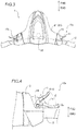
- the handle unit 6 includes the forward operating unit 10a grasped by the right hand and the rearward operating unit 10b grasped by the left hand, for example, when the rider P steers. Furthermore, the handle unit 6 includes a handle main body 61 to which the forward operating unit 10a and the rearward operating unit 10b are attached. According to the first preferred embodiment, the forward operating unit 10a and the rearward operating unit 10b are replaceable (detachable) from the handle main body 61. For example, the forward operating unit 10a and the rearward operating unit 10b shown by solid lines are detachable from a dotted portion of the handle main body 61 shown in Fig. 3 by removing fasteners (not shown).
- the handle main body 61 includes the steering shaft 62 and a case 63 that covers the steering shaft 62.
- the steering shaft 62 rotates in response to the positions of the forward operating unit 10a and the rearward operating unit 10b.
- the steering shaft 62 transmits the rotation to the deflector 1g via the steering cable (not shown).
- the forward operating unit 10a includes a throttle lever 11 (hereinafter referred to as a "lever 11") that controls the opening degree (throttle opening degree) of the throttle valve 22 of the engine 2, a grip 12 grasped by the rider P, and an operating unit housing 13 to which the lever 11 and the grip 12 are attached.
- the lever 11 is operated by being rotated with respect to the operating unit housing 13.
- the lever 11 is an example of a "throttle operator”.
- the forward operating unit 10a includes an angle detector 41, the forward signal output 42, and a board 43 disposed inside the operating unit housing 13.
- An accelerator position sensor (APS) includes the angle detector 41 and the forward signal output 42.
- the angle detector 41 detects the operation amount (the rotation angle ⁇ described below) of the lever 11.
- the forward signal output 42 outputs the output signal S to the engine controller 3 based on a detection signal (information about the rotation angle ⁇ ) from the angle detector 41.
- the angle detector 41 and the forward signal output 42 are disposed on the board 43, for example.
- the forward signal output 42 is mounted as an element on the board 43.
- the forward signal output 42 is an example of an "output".
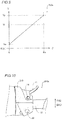
- the forward signal output 42 is electrically connected to the engine controller 3 (see Fig. 2 ). As shown in Fig. 6 , according to the first preferred embodiment, the forward signal output 42 outputs the output signal S having the output voltage value V at which the opening degree of the throttle valve 22 increases as the rotation angle ⁇ of the lever 11 increases, and outputs the output signal S having, as an upper limit, the limit output voltage value Vr at which the opening degree of the throttle valve 22 becomes smaller than that at the maximum output voltage value V M at which the opening degree of the throttle valve 22 becomes maximum, to the engine controller 3.
- the upper limit of the output voltage value V of the output signal S is limited to the limit output voltage value Vr.
- the lever 11 shown in Fig. 4 it is distinguishable by color that the upper limit of the output voltage value V of the output signal S is limited to the limit output voltage value Vr.
- the color of the lever 11 according to the first preferred embodiment is different from the color of a lever in which the upper limit of the output voltage value V of the output signal S is set (not limited) to the maximum output voltage value V M . That is, when visually recognizing the color of the lever 11, the rider P determines whether the lever 11 (forward operating unit 10a) according to the first preferred embodiment is mounted on the small boat 100 or an unlimited lever (forward operating unit) is mounted on the small boat 100.
- the forward operating unit 10a includes a rotation shaft 14.
- the rotation shaft 14 is a shaft that serves as the rotation center of the lever 11.
- the maximum angle ⁇ M is an example of a "maximum operation amount".
- the rotation shaft 14 is fixed to the operating unit housing 13 so as to be rotatable integrally with the lever 11 with respect to the operating unit housing 13.
- the rotation shaft 14 is fixed to the operating unit housing 13 via a biasing member (not shown). A biasing force is applied to the rotation shaft 14 by the biasing member, and when the rider P does not grasp the lever 11, the rotation shaft 14 moves (returns) the lever 11 to the position at a rotation angle of 0 degrees.
- the angle detector 41 faces the rotation shaft 14 in the radial direction, and detects the rotation angle ⁇ of the rotation shaft 14 as a rotation angle that serves as the operation amount.
- the angle detector 41 is an element (magnetic detection element) that detects a magnetic change, for example.
- the angle detector 41 is mounted on the board 43.
- the rotation shaft 14 includes a magnet 15.
- the thickness of the magnet 15 in the radial direction is non-uniform in a circumferential direction such that the magnitude of the magnetism detected by the angle detector 41 varies according to the rotation angle ⁇ of the rotation shaft 14.
- the angle detector 41 outputs a detection signal having a voltage value corresponding to the rotation angle ⁇ of the rotation shaft 14 to the forward signal output 42 via a circuit on the board 43.
- the forward signal output 42 includes a processor 51 including a CPU (central processing unit), for example, and a storage 52 (nonvolatile memory, for example) that stores a control program 52a and characteristics information 52b described below in advance.
- the processor 51 performs control processing based on the rotation angle ⁇ acquired from the angle detector 41 and the control program 52a and the characteristics information 52b stored in the storage 52.
- the characteristics information 52b is an example of "output limitation characteristics information".
- the characteristics information 52b is data in which the output voltage value V including the limit output voltage value Vr as an upper limit and the rotation angle ⁇ are associated with each other.
- the output signal S having the output voltage value V corresponding to the rotation angle ⁇ is output to the engine controller 3 based on (referring to) the characteristics information 52b.
- the abnormality detection output voltage value Ve (lower limit) is set as the output voltage value V corresponding to a rotation angle of 0 degrees (the operation amount is 0).
- the abnormality detection output voltage value Ve is a voltage value larger than 0 [V] and smaller than the limit output voltage value Vr, for example.
- the abnormality detection output voltage value Ve is an example of an "abnormality detection output value".
- the threshold angle ⁇ t is an example of an "operation amount threshold".
- the output voltage value V at which the opening degree of the throttle valve 22 increases as the rotation angle ⁇ increases such that the rotation angle ⁇ and the output voltage value V have a substantially linear function relationship (proportional relationship) is set. That is, according to the first preferred embodiment, the forward signal output 42 outputs, to the engine controller 3, the output signal S having the output voltage value V at which the opening degree of the throttle valve 22 increases as the rotation angle ⁇ increases such that the rotation angle ⁇ and the output voltage value V have a substantially linear function relationship (proportional relationship).
- a dotted portion in Fig. 6 shows data (hereinafter referred to as "non-limitation information") in which the output voltage value V including the maximum output voltage value V M as an upper limit (not limited) and the rotation angle ⁇ are associated with each other.
- the characteristics of a portion (range R1) of the characteristics information 52b in which the rotation angle ⁇ and the output voltage value V have a substantially linear function relationship are substantially the same as the characteristics of the range R1 of the non-limitation information. That is, in the range R1, the forward signal output 42 outputs the same output signal S as when the output voltage value V is not limited.
- the limit output voltage value Vr (constant value) is set in a range R2 in which the rotation angle ⁇ is not less than the threshold angle ⁇ t and not more than the maximum angle ⁇ M . That is, according to the first preferred embodiment, when the rotation angle ⁇ detected by the angle detector 41 is the maximum angle ⁇ M (in the range R2 of not less than the threshold angle ⁇ t and not more than the maximum angle ⁇ M ), the forward signal output 42 outputs the output signal S having the limit output voltage value Vr, assuming that the operation amount of the lever 11 is the maximum operation amount, to the engine controller 3.
- the structure of the rearward operating unit 10b is similar to the structure of the forward operating unit 10a, and thus description thereof is omitted.
- the forward signal output 42 outputs, to the engine controller 3, the output signal S having, as an upper limit, the limit output voltage value Vr at which the opening degree of the throttle valve 22 becomes smaller than that at the maximum output voltage value V M at which the opening degree of the throttle valve 22 becomes maximum. Accordingly, the horsepower of the small boat 100 (engine 2) is limited to an amount corresponding to the limit output voltage value Vr without limiting the upper limit of the rotation angle ⁇ of the lever 11 (without mechanically limiting the movable range). Consequently, unlike the case in which the movable range of the lever 11 is mechanically limited, no error is caused due to the structure that limits the movable range, and thus the upper limit of the output signal S is more accurately limited.
- the horsepower is more accurately limited as compared with the case in which the movable range of the lever 11 is mechanically limited.
- the horsepower corresponding to the limit output voltage value Vr the amount of horsepower limited by laws and regulations, for example
- the small boat 100 complies with horsepower regulations while an increase in the number of engine 2 types is significantly reduce or prevented.
- the forward signal output 42 outputs the output signal S having the limit output voltage value Vr as an upper limit to the engine controller 3 such that the horsepower of the small boat 100 is limited by changing (replacing) the forward operating unit 10a without changing the control program of the engine controller 3.
- the small boat 100 complies with horsepower regulations while the number of inspection steps of the engine controller 3 that operates the entire small boat 100 is reduced as compared with the case in which the control program of the engine controller 3 (ECU) is changed.
- the forward signal output 42 outputs the output signal S having the limit output voltage value Vr to the engine controller 3 when the operation amount (rotation angle ⁇ ) is the maximum operation amount (maximum angle ⁇ M ). Accordingly, even when the lever 11 is operated from the rotation angle ⁇ to the maximum angle ⁇ M (when the rotation angle ⁇ of the lever 11 is not limited), the output signal S having the limit output voltage value Vr as an upper limit is output, and thus the small boat 100 complies with horsepower regulations without changing the range (movable range) of the operation amount of the lever 11.
- the forward signal output 42 outputs the output signal S having the limit output voltage value Vr to the engine controller 3 when the operation amount (rotation angle ⁇ ) is equal to or larger than the threshold angle ⁇ t smaller than the maximum operation amount (maximum angle ⁇ M ). Accordingly, output of the output signal S that exceeds the limit output voltage value Vr is prevented even when the lever 11 is operated to the rotation angle ⁇ equal to or more than the predetermined threshold angle ⁇ t.
- the lever 11 is rotationally operated. Furthermore, the forward operating unit 10a includes the angle detector 41 that detects the rotation angle ⁇ of the lever 11. When the rotation angle ⁇ detected by the angle detector 41 is the maximum angle ⁇ M , the forward signal output 42 outputs the output signal S having the limit output voltage value Vr, assuming that the operation amount is the maximum operation amount, to the engine controller 3. Accordingly, the upper limit of the output voltage value V of the output signal S is limited to the limit output voltage value Vr without limiting the rotation angle ⁇ of the lever 11 to an angle smaller than the maximum angle ⁇ M (without changing the movable range).
- the lever 11 extends from the rotation shaft 14 disposed in the vicinity of the grip 12 grasped by the rider P in the radial direction of the rotation shaft 14, and is rotatable about the rotation shaft 14 toward the grip 12. Furthermore, the angle detector 41 faces the rotation shaft 14 in the radial direction, and detects the rotation angle ⁇ of the rotation shaft 14 as the operation amount.
- the forward signal output 42 outputs the output signal S having the limit output voltage value Vr, assuming that the operation amount is the maximum operation amount, to the engine controller 3. Accordingly, the rotation angle ⁇ is detected without providing a mechanical wire, and the output signal S corresponding to the rotation angle ⁇ is output to the engine controller 3. Consequently, a mechanical wire is not provided, and thus an increase in the number of components in the small boat 100 is significantly reduced or prevented, and an increase in the load required to rotate the lever 11 is significantly reduced or prevented.
- the forward signal output 42 outputs the output signal S having the output voltage value V corresponding to the rotation angle ⁇ to the engine controller 3 based on the characteristics information 52b in which the output voltage value V (output value) including the limit output voltage value Vr (limit output value) as an upper limit and the rotation angle ⁇ (operation amount) are associated with each other. Accordingly, the forward signal output 42 easily generates the output signal S having the output voltage value V corresponding to the rotation angle ⁇ and including the limit output voltage value Vr as an upper limit, referring to the characteristics information 52b, and outputs the output signal S to the engine controller 3.
- the rotation angle ⁇ and the output voltage value V as the output value are associated with each other. Furthermore, the forward signal output 42 outputs the output signal S having the limit output voltage value Vr, which is the output voltage value V corresponding to the limit output value, as an upper limit to the engine controller 3. Accordingly, the forward signal output 42 outputs the voltage value corresponding to the rotation angle ⁇ , referring to the characteristics information 52b, and thus the forward signal output 42 easily outputs the output signal S having the output voltage value V including the limit output voltage value Vr as an upper limit.
- the forward operating unit 10a includes the lever 11 and the forward signal output 42, and is replaceable from the boat body 1. Accordingly, a forward operating unit to which the output signal S having the maximum output voltage value V M as an upper limit is output from the forward signal output is replaced with the forward operating unit 10a to which the output signal S having the limit output voltage value Vr as an upper limit is output from the forward signal output 42 such that a state in which the upper limit of the output voltage value V of the output signal S output from the forward signal output 42 becomes the maximum output voltage value V M is easily changed to a state in which the upper limit of the output voltage value V of the output signal S output from the forward signal output 42 becomes the limit output voltage value Vr using the same type of engine 2.
- the rider P recognizes whether or not the upper limit of the output voltage value V of the output signal S output from the forward signal output 42 is limited to the limit output voltage value Vr by visually recognizing the forward operating unit 10a.
- the forward operating unit 10a (preferably the lever 11), it is distinguishable by color that the upper limit of the output voltage value V of the output signal S is limited to the limit output voltage value Vr. Accordingly, the color of the forward operating unit 10a in which the upper limit of the output voltage value V of the output signal S output from the forward signal output 42 is limited to the limit output voltage value Vr is made different from the color of a forward operating unit in which the upper limit of the output voltage value V is not limited to the limit output voltage value Vr such that the rider P more intuitively recognizes whether or not the upper limit of the output voltage value V of the output signal S is limited to the limit output voltage value Vr.
- the forward signal output 42 outputs the abnormality detection output voltage value Ve as the output signal S to the engine controller 3 when the rotation angle ⁇ is 0, and outputs the output signal S having the limit output voltage value Vr, which is larger than the abnormality detection output voltage value Ve, as an upper limit to the engine controller 3 when the rotation angle ⁇ is larger than 0. Furthermore, the engine controller 3 stops the engine 2 or sets the engine 2 to idle when acquiring the output signal S having the output voltage value V less than the abnormality detection output voltage value Ve.
- the small boat 100 includes an abnormality detection function of stopping the engine 2 or setting the engine 2 to idle when acquiring the output signal S having the output voltage value V less than the abnormality detection output voltage value Ve, and the output signal S having the limit output voltage value Vr as an upper limit is output to the engine controller 3.
- a small boat 200 according to a second preferred embodiment The structure of a small boat 200 according to a second preferred embodiment is now described with reference to Figs. 1 and 7 .
- an output signal S having an output voltage value V at which the opening degree of a throttle valve 22 increases as the rotation angle ⁇ of a lever 11 increases over a range R3 from a rotation angle of 0 degrees to a maximum angle ⁇ M is output, unlike the small boat 100 according to the first preferred embodiment in which the constant limit output voltage value Vr is output when the rotation angle ⁇ is equal to or more than the threshold angle ⁇ t.
- the same structures as those of the first preferred embodiment are denoted by the same reference numerals, and description thereof is omitted.
- the small boat 200 includes a handle unit 206.
- the handle unit 206 includes a forward operating unit 210a and a rearward operating unit 210b.
- the forward operating unit 210a includes a forward signal output 242.
- the forward signal output 242 includes a storage 252 that stores characteristics information 252b.
- the rotation angle ⁇ and the output voltage value V including a limit output voltage value Vr as an upper limit are associated with each other such that the rotation angle ⁇ and the output voltage value V have a substantially linear function relationship over the range R3 in which the rotation angle ⁇ (operation amount) of the lever 11 (see Fig. 4 ) is 0 degrees to the maximum angle ⁇ M (maximum operation amount).
- the forward signal output 242 outputs, to an engine controller 3, the output signal S having the output voltage value V (high output voltage value V) at which the opening degree of the throttle valve 22 increases as the rotation angle ⁇ increases over the range R3 in which the rotation angle ⁇ of the lever 11 is 0 degrees to the maximum angle ⁇ M .
- the output voltage value V including the limit output voltage value Vr as an upper limit and the rotation angle ⁇ have a substantially linear function relationship.
- the slope of the output voltage value V with respect to the rotation angle ⁇ in the characteristics information 252b (solid line) is smaller than the slope of the output voltage value V with respect to the rotation angle ⁇ in the range R3 of non-limitation information (dotted line).
- the output voltage value V corresponding to the maximum angle ⁇ M becomes the limit output voltage value Vr.
- the remaining structures of the second preferred embodiment are similar to those of the first preferred embodiment.
- the forward signal output 242 outputs, to the engine controller 3, the output signal S having the output voltage value V at which the throttle opening degree increases as the rotation angle ⁇ increases over the range R3 from a rotation angle ⁇ of 0 degrees to the maximum angle ⁇ M .
- the output voltage value V corresponding to the rotation angle ⁇ is output (the throttle opening degree is adjusted) over the range R3 from the rotation angle ⁇ of 0 degrees to the maximum angle ⁇ M while the upper limit of the output voltage value V is limited to the limit output voltage value Vr, and thus while the small boat 200 complies with horsepower regulations, the output voltage value V is more precisely adjusted as compared with the case in which the output signal S having the limit output voltage value Vr (constant value) at the rotation angle ⁇ equal to or more than the threshold angle ⁇ t is output.
- the forward signal output 242 outputs, to the engine controller 3, the output signal S having the output voltage value V at which the throttle opening degree increases as the rotation angle ⁇ increases such that the rotation angle ⁇ and the output voltage value V have a substantially linear function relationship over the range R3 from a rotation angle ⁇ of 0 degrees to the maximum operation amount ⁇ M . Accordingly, even when the upper limit of the output voltage value V is limited to the limit output voltage value Vr, a rider P more intuitively adjusts the output voltage value V as compared with the case in which the rotation angle ⁇ and the output voltage value V have a relatively complicated relationship (output characteristics) other than the linear function.
- the remaining effects of the second preferred embodiment are similar to those of the first preferred embodiment.
- a forward signal output 342 includes a first storage 352 that stores limitation characteristics information 352a and a second storage 353 that stores non-limitation characteristics information 353a.
- first storage 352 that stores limitation characteristics information 352a
- second storage 353 that stores non-limitation characteristics information 353a.
- the small boat 300 includes a handle unit 306.
- the handle unit 306 includes a forward operating unit 310a and a rearward operating unit 310b.
- the forward operating unit 310a includes the forward signal output 342.
- the forward signal output 342 includes a processor 351, the first storage 352 that stores the limitation characteristics information 352a, and the second storage 353 that stores the non-limitation characteristics information 353a.
- the limitation characteristics information 352a is similar to the characteristics information 52b (see Fig. 6 ) according to the first preferred embodiment. As shown in Fig.
- an output voltage value V including a maximum output voltage value V M as an upper limit and a rotation angle ⁇ are associated with each other.
- the limitation characteristics information 352a is an example of "output limitation characteristics information”.
- the non-limitation characteristics information 353a is an example of "output non-limitation characteristics information”.
- the forward operating unit 310a includes a setter 360 that sets one of the limitation characteristics information 352a and the non-limitation characteristics information 353a.
- the setter 360 includes a setting operator 361 and a setting switch 362.
- the setting operator 361 is disposed on an operating unit housing 313 of the forward operating unit 310a, and is a push button, for example.
- one operation method (pressing for a short time, for example) of the existing operator of the forward operating unit 310a is changed to another operation method (pressing for a long time, for example) such that the operation is received as an operation on the setting operator 361.
- the setting switch 362 is a switch that switches between a state in which the processor 351 is connected to the first storage 352 and a state in which the processor 351 is connected to the second storage 353 according to an operation on the setting operator 361.
- the forward signal output 342 outputs an output signal S based on the limitation characteristics information 352a to an engine controller 3 when the processor 351 is connected to the first storage 352, and outputs an output signal S based on the non-limitation characteristics information 353a to the engine controller 3 when the processor 351 is connected to the second storage 353.
- the forward signal output 342 outputs the output signal S based on the limitation characteristics information 352a to the engine controller 3 due to setting of the setter 360.
- the forward signal output 342 outputs the output signal S based on the non-limitation characteristics information 353a to the engine controller 3 due to setting of the setter 360.
- the rearward operating unit 310b is structurally similar to the forward operating unit 310a.
- the remaining structures of the third preferred embodiment are similar to those of the first preferred embodiment.
- the forward operating unit 310a includes the setter 360 that sets one of the limitation characteristics information 352a and the non-limitation characteristics information 353a in which the output voltage value V including the maximum output voltage value V M as an upper limit and the rotation angle ⁇ are associated with each other. Furthermore, the forward signal output 342 outputs the output signal S having the output voltage value V corresponding to the rotation angle ⁇ to the engine controller 3 based on one of the limitation characteristics information 352a and the non-limitation characteristics information 353a set by the setter 360.
- setting of the limitation characteristics information 352a and the non-limitation characteristics information 353a is switched such that output signals S having different output voltage values V as upper limits are output from the forward signal output 342 using the same type of engine 2 (small boat 300). Consequently, the upper limit of the output voltage value V of the output signal S is changed according to the limited horsepower using the same type of engine 2 (small boat 300), and thus even when the rider P is changed (to a rider with a different license) or even when the small boat 300 is moved across countries in which different horsepower regulations are set up, the small boat 300 complies with horsepower regulations.
- the setter 360 includes the setting operator 361 that receives an operation of setting one of the limitation characteristics information 352a and the non-limitation characteristics information 353a. Accordingly, the rider P or a setting worker operates the setting operator 361 to easily set (select) one of the limitation characteristics information 352a and the non-limitation characteristics information 353a.
- the forward signal output 342 includes the first storage 352 that stores the limitation characteristics information 352a and the second storage 353 that stores the non-limitation characteristics information 353a. Accordingly, the limitation characteristics information 352a and the non-limitation characteristics information 353a are stored in the first storage 352 and the second storage 353 of the forward signal output 342, and thus the output signal S is generated using the limitation characteristics information 352a and the non-limitation characteristics information 353a stored in the first storage 352 and the second storage 353 without providing the limitation characteristics information 352a and the non-limitation characteristics information 353a separately from the forward signal output 342 (small boat 300).
- the limitation characteristics information 352a and the non-limitation characteristics information 353a are written in the first storage 352 and the second storage 353 of the forward signal output 342 such that the forward signal output 342 easily outputs the output signal S corresponding to the limitation characteristics information 352a or the non-limitation characteristics information 353a.
- the remaining effects of the third preferred embodiment are similar to those of the first preferred embodiment.
- a small boat 400 when a lever 11 is at a maximum angle ⁇ M , an output signal S is output in a state in which a maximum output voltage value V M of a maximum signal S M output from a maximum signal output 442a is reduced to a limit output voltage value Vr.
- the same structures as those of the first to third preferred embodiments are denoted by the same reference numerals, and description thereof is omitted.
- the small boat 400 includes a handle unit 406.
- the handle unit 406 includes a forward operating unit 410a and a rearward operating unit 410b.
- the forward operating unit 410a includes a forward signal output 442.
- the forward signal output 442 includes the maximum signal output 442a that outputs the maximum signal S M , which is a signal having the maximum output voltage value V M , when the rotation angle ⁇ of the lever 11 is the maximum angle ⁇ M , and an output limiter 442b that outputs the output signal S in a state in which the maximum output voltage value V M of the maximum signal S M output from the maximum signal output 442a is reduced to the limit output voltage value Vr.
- the maximum signal output 442a includes a processor 451a and a storage 452a that stores non-limitation characteristics information 353a (similar to the non-limitation characteristics information 353a according to the third preferred embodiment).
- the maximum signal output 442a outputs an output signal Sa having the maximum output voltage value V M as an upper limit to the output limiter 442b.
- the output signal Sa has the maximum output voltage value V M , the same is defined as the maximum signal S M .
- the output limiter 442b lowers the output voltage value V of the output signal Sa.
- the output limiter 442b includes a resistor.
- the output limiter 442b converts the output signal Sa having the maximum output voltage value V M as an upper limit to the output signal S having the limit output voltage value Vr as an upper limit, and outputs the same to an engine controller 3.
- the rearward operating unit 410b is structurally similar to the forward operating unit 410a.
- the remaining structures of the fourth preferred embodiment are similar to those of the first preferred embodiment.
- the forward signal output 442 includes the maximum signal output 442a that outputs the maximum signal S M , which is a signal having the maximum output voltage value V M , when the rotation angle ⁇ is the maximum angle ⁇ M , and the output limiter 442b that outputs the output signal S in a state in which the maximum output voltage value V M of the maximum signal S M output from the maximum signal output 442a is reduced to the limit output voltage value Vr when the rotation angle ⁇ is the maximum angle ⁇ M .
- the output limiter 442b is added to the structure of the existing maximum signal output 442a such that the forward signal output 442 easily outputs the output signal S having the limit output voltage value Vr as an upper limit.
- the small boat is preferably a PWC and a water jet propelled boat in each of the first to fourth preferred embodiments described above, the present invention is not restricted to this.
- a propulsion device an inboard motor or an outboard motor
- a jet may alternatively be provided in the small boat.
- the rotation angle of the lever is preferably used as the operation amount in each of the first to fourth preferred embodiments described above, the present invention is not restricted to this.
- the parallel movement amount of the operator that moves in parallel may alternatively be used as the operation amount, or the grip may alternatively be rotatable and the rotation angle of the grip may alternatively be used as the operation amount.
- the forward signal output preferably outputs, to the engine controller, the output signal having the output voltage value that increases as the rotation angle increases such that the rotation angle of the lever and the output voltage value have a substantially linear function relationship in each of the first to fourth preferred embodiments described above
- the present invention is not restricted to this.
- the forward signal output may alternatively output, to the engine controller, the output signal having the output voltage value that increases as the rotation angle increases such that the rotation angle of the lever and the output voltage value have a quadratic function or logarithmic function relationship.
- the present invention is not restricted to this.
- a mechanical wire may alternatively be connected to the rotation shaft, and the rotation angle may alternatively be detected by the angle detector disposed away from the rotation shaft (in the vicinity of the engine controller, for example).
- the output value is preferably an output voltage value in each of the first to fourth preferred embodiments described above, the present invention is not restricted to this.
- the output value may alternatively be an output current value.
- the present invention is not restricted to this.
- the engine controller may alternatively perform control such that the throttle opening degree increases as the output voltage value decreases.
- the "upper limit of the output voltage value" indicates the smallest output voltage value at which the throttle opening degree becomes maximum.
- the forward signal output preferably outputs the output voltage value corresponding to the rotation angle with the processor that refers to the characteristics information stored in the storage in each of the first to fourth preferred embodiments described above
- the present invention is not restricted to this.
- the forward signal output may alternatively include a combination (hardware) of a plurality of electric components disposed on the board.
- the characteristics information is preferably set from one piece of limitation characteristics information and one piece of non-limitation characteristics information in the third preferred embodiment described above, the present invention is not restricted to this.
- the characteristics information may alternatively be set from a plurality of pieces of limitation characteristics information and one piece of non-limitation characteristics information.
- the output limiter 442b preferably includes a resistor that lowers the voltage value, and the output signal S is preferably output in a state in which the maximum output voltage value V M is reduced to the limit output voltage value Vr in the fourth preferred embodiment described above, the present invention is not restricted to this.
- the output limiter 442b may alternatively include an electronic component that serves as a limiter that limits a voltage value exceeding the limit output voltage value Vr to the limit output voltage value Vr, and when the rotation angle ⁇ is equal to or more than the threshold angle ⁇ t, the output signal S may alternatively be output in a state in which the maximum output voltage value V M of the maximum signal S M output from the maximum signal output 442a is limited to the limit output voltage value Vr.
- an indicator indicating that the upper limit of the output voltage value of the output signal is limited to the limit output voltage value may alternatively be affixed to the operating unit housing or the grip such that it is distinguishable.
- the lower limit of the output voltage value is preferably set as the abnormality detection output voltage value in each of the first to fourth preferred embodiments described above, the present invention is not restricted to this.
- the lower limit of the output voltage value may alternatively be 0 [V].
Landscapes
- Engineering & Computer Science (AREA)
- Chemical & Material Sciences (AREA)
- Combustion & Propulsion (AREA)
- Mechanical Engineering (AREA)
- Ocean & Marine Engineering (AREA)
- Physics & Mathematics (AREA)
- General Physics & Mathematics (AREA)
- Automation & Control Theory (AREA)
- Control Of Throttle Valves Provided In The Intake System Or In The Exhaust System (AREA)
- Combined Controls Of Internal Combustion Engines (AREA)
- Electrical Control Of Air Or Fuel Supplied To Internal-Combustion Engine (AREA)
Abstract
Description
- The present invention relates to a small boat.
- A throttle operating device (a small boat) including a throttle operator is known in general. Such a throttle operating device (a small boat) is disclosed in Japanese Patent No.
5543224 - Japanese Patent No.
5543224 - Here, depending on an area (country) in which a small boat including a throttle operating device as disclosed in Japanese Patent No.
5543224 - It is an object of the present invention to provide small boat and throttle operating method for a small boat in which the horsepower is more accurately limited. Accordingly to the present invention said object is solved by a small boat having the features of independent claim 1. Moreover, said object is also solved by a throttle operating method for a small boat having the features of
independent claim 15. Preferred embodiments are laid down in the dependent claims. - A small boat according to a preferred embodiment includes a throttle operator through which a throttle opening degree of an engine is controlled, an engine controller that is configured to control the throttle opening degree, and an forward signal output that is configured to output, to the engine controller, an output signal having an output value at which the throttle opening degree increases as an operation amount of the throttle operator increases, and is configured to output, to the engine controller, the output signal having, as an upper limit, a limit output value at which the throttle opening degree becomes smaller than that at a maximum output voltage value at which the throttle opening degree becomes maximum.
- In a small boat according to a preferred embodiment, the forward signal output is configured to output, to the engine controller, the output signal having, as an upper limit, the limit output value at which the throttle opening degree becomes smaller than that at the maximum output value at which the throttle opening degree becomes maximum. Accordingly, the horsepower of the small boat (engine) is limited to an amount corresponding to the limit output value without limiting the upper limit of the operation amount of the throttle operator (without mechanically limiting the movable range). Consequently, unlike the case in which the movable range of the throttle operator is mechanically limited, no error is caused due to the structure that limits the movable range, and thus the upper limit of the output signal is more accurately limited. That is, the horsepower is more accurately limited as compared with the case in which the movable range of the throttle operator is mechanically limited. In addition, even when the maximum horsepower (the amount of horsepower to be a specification value) of the engine mounted on the small boat is larger than the horsepower corresponding to the limit output value (the amount of horsepower limited by laws and regulations, for example), the horsepower of the engine of the small boat is limited to an amount corresponding to the limit output value. Thus, it is not necessary to prepare the engine that sets the horsepower corresponding to the limit output value to the maximum horsepower separately from the engine having the maximum horsepower larger than the horsepower corresponding to the limit output value, and thus an increase in the number of engine types in the small boat is significantly reduced or prevented. Consequently, the small boat complies with horsepower regulations while an increase in the number of engine types is significantly reduce or prevented. In addition, when the horsepower is limited by the engine controller (ECU), it is necessary to prepare a plurality of types of control programs of the engine controller. In this case, it is necessary to design the control program of the engine controller for each limited horsepower, and when the control program is changed, an inspection to operate the engine controller is required for each small boat. Thus, the number of inspection steps is increased. On the other hand, according to preferred embodiments, the forward signal output is configured to output the output signal having the limit output value as an upper limit to the engine controller such that the horsepower of the small boat is limited by changing (replacing) the output (throttle operating device, for example) without changing the control program of the engine controller. Thus, the small boat complies with horsepower regulations while the number of inspection steps of the engine controller that operates the entire small boat is reduced as compared with the case in which the control program of the engine controller (ECU) is changed.
- In a small boat according to a preferred embodiment, the forward signal output is configured to output the output signal having the limit output value to the engine controller when the operation amount is a maximum operation amount. Accordingly, even when the throttle operator is operated to the maximum operation amount (when the operation amount of the throttle operator is not limited), the output signal having the limit output value as an upper limit is output, and thus the small boat complies with horsepower regulations without changing the range (movable range) of the operation amount of the throttle operator.
- In such a case, the forward signal output is configured to output the output signal having the limit output value to the engine controller when the operation amount is equal to or larger than an operation amount threshold that is smaller than the maximum operation amount. Accordingly, output of the output signal that exceeds the limit output value is prevented even when the throttle operator is operated to the operation amount equal to or larger than the predetermined operation amount threshold.
- In a small boat in which the output signal having the limit output value is output when the operation amount is the maximum operation amount, the forward signal output is configured to output, to the engine controller, the output signal having the output value at which the throttle opening degree increases as the operation amount increases over a range from the operation amount of 0 to the maximum operation amount. Accordingly, the output value corresponding to the operation amount is output (the throttle opening degree is adjusted) over the range from the operation amount of 0 to the maximum operation amount while the upper limit of the output value is limited to the limit output value, and thus while the small boat complies with horsepower regulations, the output value is more precisely adjusted as compared with the case in which the output signal having the limit output value (constant value) at the operation amount equal to or larger than the operation amount threshold is output.
- In such a case, the forward signal output is configured to output, to the engine controller, the output signal having the output value at which the throttle opening degree increases as the operation amount increases such that the operation amount and the output value have a linear function relationship over the range from the operation amount of 0 to the maximum operation amount. Accordingly, even when the upper limit of the output value is limited to the limit output value, a boat operator more intuitively adjusts the output value as compared with the case in which the operation amount and the output value have a relatively complicated relationship (output characteristics) other than the linear function.
- In a small boat in which the output signal having the limit output value is output when the operation amount is the maximum operation amount, the throttle operator is preferably rotationally operated, the small boat preferably further includes an angle detector that is configured to detect a rotation angle of the throttle operator, and the forward signal output is configured to output the output signal having the limit output value, assuming that the operation amount is the maximum operation amount, to the engine controller when the rotation angle that is detected by the angle detector is a maximum angle. Accordingly, the upper limit of the output value of the output signal is limited to the limit output value without limiting the rotation angle of the throttle operator to an angle smaller than the maximum angle (without changing the movable range).
- In such a case, the throttle operator preferably extends from a rotation shaft disposed in a vicinity of a grip grasped by a boat operator in a radial direction of the rotation shaft, and is preferably a lever that is configured to be rotated about the rotation shaft toward the grip, the angle detector preferably faces the rotation shaft in the radial direction, and is configured to detect a rotation angle of the rotation shaft as the operation amount, and the forward signal output is configured to output the output signal having the limit output value, assuming that the operation amount is the maximum operation amount, to the engine controller when the rotation angle that is detected by the angle detector is the maximum angle. Here, a small boat may conceivably include an angle detector disposed away from a rotation shaft of a lever and that detects the rotation angle of the rotation shaft via a mechanical wire provided on the rotation shaft. However, in such a small boat, due to the mechanical wire, the number of components increases, and the load required to rotate the lever increases. On the other hand, according to preferred embodiments, the angle detector faces the rotation shaft in the radial direction and detects the rotation angle of the rotation shaft as the operation amount such that the rotation angle is detected without providing a mechanical wire, and the output signal corresponding to the rotation angle is output to the engine controller. Consequently, a mechanical wire is not provided, and thus an increase in the number of components in the small boat is significantly reduced or prevented while an increase in the load required to rotate the lever is significantly reduced or prevented.
- In a small boat according to a preferred embodiment, the forward signal output is configured to output the output signal having the output value corresponding to the operation amount to the engine controller based on output limitation characteristics information in which the output value including the limit output value as an upper limit and the operation amount are associated with each other. Accordingly, the output easily generates the output signal having the output value corresponding to the operation amount and including the limit output value as an upper limit, referring to the output limitation characteristics information, and outputs the output signal to the engine controller.
- In such a case, in the output limitation characteristics information, the operation amount and an output voltage value as the output value are preferably associated with each other, and the forward signal output is configured to output the output signal having a limit output voltage value, which is the output voltage value corresponding to the limit output value, as an upper limit to the engine controller. Accordingly, the forward signal output is configured to output the voltage value corresponding to the operation amount, referring to the output limitation characteristics information, and thus the forward signal output is configured to easily output the output signal having the output value including the limit output value as an upper limit.
- A small boat in which the output signal is output based on the output limitation characteristics information preferably further includes a setter that is configured to set one of the output limitation characteristics information and output non-limitation characteristics information in which the output value including the maximum output voltage value as an upper limit and the operation amount are associated with each other, and the forward signal output is configured to output the output signal having the output value corresponding to the operation amount to the engine controller based on one of the output limitation characteristics information and the output non-limitation characteristics information set by the setter. Accordingly, setting of the output limitation characteristics information and the output non-limitation characteristics information is switched such that output signals having different output values as upper limits are output from the output using the same type of engine (small boat). Consequently, the upper limit of the output value of the output signal is changed according to the limited horsepower (horsepower regulations) using the same type of engine (small boat), and thus even when the boat operator is changed (to a boat operator with a different license) or even when the small boat is moved across countries in which different horsepower regulations are set up, the small boat complies with horsepower regulations.
- In such a case, the setter preferably includes a setting operator that is configured to receive an operation of setting one of the output limitation characteristics information and the output non-limitation characteristics information. Accordingly, the boat operator or a setting worker operates the setting operator to easily set (select) one of the output limitation characteristics information and the output non-limitation characteristics information.
- When the small boat includes the setter, the output preferably includes a storage that is configured to store the output limitation characteristics information and the output non-limitation characteristics information. Accordingly, the output limitation characteristics information and the output non-limitation characteristics information are stored in the storage of the output, and thus the output signal is generated using the output limitation characteristics information and the output non-limitation characteristics information stored in the storage without providing the output limitation characteristics information and the output non-limitation characteristics information separately from the output (small boat).
- In a small boat in which the output signal having the limit output value is output when the operation amount is the maximum operation amount, the output preferably includes a maximum signal output that is configured to output a maximum signal, which is a signal having the maximum output voltage value, when the operation amount is the maximum operation amount, and an output limiter that is configured to output the output signal in a state in which the maximum output voltage value of the maximum signal output from the maximum signal output is reduced to the limit output value when the operation amount is the maximum operation amount, or is configured to output the output signal in a state in which the maximum output voltage value of the maximum signal output from the maximum signal output is limited to the limit output value when the operation amount is equal to or larger than an operation amount threshold that is smaller than the maximum operation amount. Accordingly, the output limiter is added to the structure of the existing output such that the output easily outputs the output signal having the limit output value as an upper limit.
- A small boat according to a preferred embodiment preferably further includes a throttle operating device main body in which the throttle operator and the output are disposed and being replaceable from a boat body. Accordingly, a throttle operating device main body to which the output signal having the maximum output value as an upper limit is output from the output is replaced with the throttle operating device main body to which the output signal having the limit output value as an upper limit is output from the output such that a state in which the upper limit of the output value of the output signal output from the output becomes the maximum output value is easily changed to a state in which the upper limit of the output value of the output signal output from the output becomes the limit output value using the same type of engine.
- In such a case, on the throttle operating device main body, it is preferably visually distinguishable that an upper limit of the output value of the output signal is limited to the limit output value. Accordingly, even when the same type of engine is used, the boat operator recognizes whether or not the upper limit of the output value of the output signal output from the output is limited to the limit output value by visually recognizing the throttle operating device main body.
- The above and other elements, features, steps, characteristics and advantages of preferred embodiments will become more apparent from the following detailed description of the preferred embodiments with reference to the attached drawings.
-
-
Fig. 1 is a side sectional view showing the overall structure of a small boat according to a first preferred embodiment. -
Fig. 2 is a block diagram showing the structure of the small boat according to the first preferred embodiment. -
Fig. 3 is a plan view showing the structure of a handle unit according to the first preferred embodiment. -
Fig. 4 is a plan view showing the structure of a forward throttle operating unit according to the first preferred embodiment. -
Fig. 5 is a diagram illustrating detection of a rotation angle according to the first preferred embodiment. -
Fig. 6 is a diagram illustrating characteristics information according to the first preferred embodiment. -
Fig. 7 is a diagram illustrating characteristics information according to a second preferred embodiment. -
Fig. 8 is a block diagram showing the structure of a small boat according to a third preferred embodiment. -
Fig. 9 is a diagram illustrating unlimited characteristics information according to the third preferred embodiment. -
Fig. 10 is a diagram illustrating the placement position of a setting operator according to the third preferred embodiment. -
Fig. 11 is a block diagram showing the structure of a small boat according to a fourth preferred embodiment. -
Fig. 12 is a diagram illustrating the structure of a forward signal output according to the fourth preferred embodiment. - Preferred embodiments are hereinafter described with reference to the drawings.
- The structure of a
small boat 100 according to a first preferred embodiment is now described with reference toFigs. 1 to 6 . Thesmall boat 100 is a personal watercraft (PWC), for example, and is a water jet propelled boat (water motorcycle). That is, thesmall boat 100 is a straddled watercraft. - As shown in
Fig. 1 , thesmall boat 100 includes a boat body 1, anengine 2, anengine controller 3, afuel tank 4, a fuel injection system 5 (hereinafter referred to as an "FI system 5"), and ahandle unit 6 including a forwardthrottle operating unit 10a (hereinafter referred to as a "forward operatingunit 10a"). The forwardthrottle operating unit 10a is an example of a "throttle operating device" or a "throttle operating device main body". - The boat body 1 includes a
deck 1a and ahull 1b. The boat body 1 is immersed up to a predetermined height (a water surface T inFig. 1 ) in a stationary state. Anengine room 1c that houses theengine 2 driven when the boat body 1 is propelled, theengine controller 3, thefuel tank 4, and theFl system 5 is provided in the boat body 1. - The
engine 2 obtains a drive force to rotate acrankshaft 21 by burning an air-fuel mixture in a combustion chamber. Specifically, theengine 2 includes athrottle valve 22 and athrottle valve actuator 23. The opening degree (throttle opening degree) of thethrottle valve 22 is changed by thethrottle valve actuator 23 such that the amount of air supplied to the combustion chamber of theengine 2 is adjusted. As the opening degree of thethrottle valve 22 increases, the rotational speed of theengine 2 increases, and the horsepower of theengine 2 increases. TheFl system 5 includes a fuel injection system that supplies fuel at the predetermined timing and an ignition system that ignites an air-fuel mixture at the predetermined timing. Thethrottle valve actuator 23 and theFI system 5 are electrically connected to theengine controller 3, and are controlled based on commands from theengine controller 3. - The
crankshaft 21 is connected to an impeller shaft 24 via a coupling (not shown). The impeller shaft 24 extends rearward from theengine room 1c. An impeller 25 is attached in the vicinity of a rear end of the impeller shaft 24. The impeller 25 is disposed inside an impeller housing 1e connected to a rear portion of awater intake 1d, suctions water below the water surface T from thewater intake 1d, and jets the water rearward from a nozzle 1f provided behind the impeller housing 1e. - The boat body 1 includes a deflector 1g and a
bucket 1h. The deflector 1g is located behind the nozzle 1f, and changes the direction of the water jetted rearward from the nozzle 1f to a right-left direction. Thehandle unit 6 is operated such that the orientation of the deflector 1g is changed via a steering cable (not shown) connected to a steering shaft 62 (seeFig. 3 ) of thehandle unit 6 described below. That is, when a pair ofgrips 12 described below are operated by a rider P, the orientation of the deflector 1g is changed, and thesmall boat 100 is steered. - The
bucket 1h is moved between the upper side and the rear side of the deflector 1g by abucket actuator 1i. When thebucket 1h is moved to the rear side of the deflector 1g, thebucket 1h changes the direction of water jetted rearward from the nozzle 1f and the deflector 1g to a forward direction. The driving of thebucket actuator 1i is controlled by theengine controller 3, as shown inFig. 2 . - As shown in
Fig. 1 , aseat 1j on which the rider P is seated and thehandle unit 6 operated to steer the boat body 1 are provided on a portion of thedeck 1a above theengine 2 in the boat body 1. Thehandle unit 6 is disposed in front of theseat 1j. - As shown in
Fig. 2 , theengine controller 3 is an ECU (engine control unit), and controls the driving of theengine 2 based on an operation signal (output signal S) from thehandle unit 6. Specifically, theengine controller 3 is electrically connected to theforward operating unit 10a (forward signal output 42) and a rearwardthrottle operating unit 10b (hereinafter referred to as a "rearward operatingunit 10b"). Theengine controller 3 controls the driving of thebucket actuator 1i, theFI system 5, and thethrottle valve actuator 23 based on a control program. - The
engine controller 3 drives thethrottle valve actuator 23 such that the opening degree of thethrottle valve 22 increases as the output voltage value V of the acquired output signal S increases. When acquiring a maximum output voltage value VM, theengine controller 3 drives thethrottle valve actuator 23 such that the opening degree of thethrottle valve 22 is maximum (fully opened, for example). - When the output voltage value V of the output signal S from the
forward operating unit 10a is larger than the output voltage value V of the output signal S from therearward operating unit 10b, theengine controller 3 controls thebucket actuator 1i to move thebucket 1h to the upper side of the deflector 1g so as to move thesmall boat 100 forward. When the output voltage value V of the output signal S from theforward operating unit 10a is smaller than the output voltage value V of the output signal S from therearward operating unit 10b, theengine controller 3 controls thebucket actuator 1i to move thebucket 1h to the rear side of the deflector 1g so as to move thesmall boat 100 rearward. - According to the first preferred embodiment, when acquiring the output signal S having the output voltage value V less than an abnormality detection output voltage value Ve described below from the
forward operating unit 10a or therearward operating unit 10b, theengine controller 3 stops the driving of theengine 2 or sets theengine 2 to idle. Note that the term "idle" indicates a state in which theengine controller 3 controls thethrottle valve actuator 23 and theFI system 5 such that theengine 2 reaches a rotational speed within an idling rotational speed range. That is, when acquiring the output signal S having the output voltage value V (0 [V], for example) less than the abnormality detection output voltage value Ve as a lower limit from theforward operating unit 10a or therearward operating unit 10b, theengine controller 3 detects the abnormality of theforward operating unit 10a or therearward operating unit 10b, or the abnormality of wiring between theforward operating unit 10a or therearward operating unit 10b and theengine controller 3. - As shown in
Fig. 3 , thehandle unit 6 includes theforward operating unit 10a grasped by the right hand and therearward operating unit 10b grasped by the left hand, for example, when the rider P steers. Furthermore, thehandle unit 6 includes a handlemain body 61 to which theforward operating unit 10a and therearward operating unit 10b are attached. According to the first preferred embodiment, theforward operating unit 10a and therearward operating unit 10b are replaceable (detachable) from the handlemain body 61. For example, theforward operating unit 10a and therearward operating unit 10b shown by solid lines are detachable from a dotted portion of the handlemain body 61 shown inFig. 3 by removing fasteners (not shown). - The handle
main body 61 includes the steeringshaft 62 and acase 63 that covers the steeringshaft 62. The steeringshaft 62 rotates in response to the positions of theforward operating unit 10a and therearward operating unit 10b. The steeringshaft 62 transmits the rotation to the deflector 1g via the steering cable (not shown). - As shown in
Fig. 4 , according to the first preferred embodiment, theforward operating unit 10a includes a throttle lever 11 (hereinafter referred to as a "lever 11") that controls the opening degree (throttle opening degree) of thethrottle valve 22 of theengine 2, agrip 12 grasped by the rider P, and anoperating unit housing 13 to which thelever 11 and thegrip 12 are attached. Thelever 11 is operated by being rotated with respect to theoperating unit housing 13. Thelever 11 is an example of a "throttle operator". - As shown in
Fig. 5 , theforward operating unit 10a includes anangle detector 41, theforward signal output 42, and aboard 43 disposed inside the operatingunit housing 13. An accelerator position sensor (APS) includes theangle detector 41 and theforward signal output 42. Theangle detector 41 detects the operation amount (the rotation angle θ described below) of thelever 11. Theforward signal output 42 outputs the output signal S to theengine controller 3 based on a detection signal (information about the rotation angle θ) from theangle detector 41. Theangle detector 41 and theforward signal output 42 are disposed on theboard 43, for example. Theforward signal output 42 is mounted as an element on theboard 43. Theforward signal output 42 is an example of an "output". - The
forward signal output 42 is electrically connected to the engine controller 3 (seeFig. 2 ). As shown inFig. 6 , according to the first preferred embodiment, theforward signal output 42 outputs the output signal S having the output voltage value V at which the opening degree of thethrottle valve 22 increases as the rotation angle θ of thelever 11 increases, and outputs the output signal S having, as an upper limit, the limit output voltage value Vr at which the opening degree of thethrottle valve 22 becomes smaller than that at the maximum output voltage value VM at which the opening degree of thethrottle valve 22 becomes maximum, to theengine controller 3. - On the
forward operating unit 10a, it is visually distinguishable that the upper limit of the output voltage value V of the output signal S is limited to the limit output voltage value Vr. Specifically, on thelever 11 shown inFig. 4 , it is distinguishable by color that the upper limit of the output voltage value V of the output signal S is limited to the limit output voltage value Vr. More specifically, the color of thelever 11 according to the first preferred embodiment is different from the color of a lever in which the upper limit of the output voltage value V of the output signal S is set (not limited) to the maximum output voltage value VM. That is, when visually recognizing the color of thelever 11, the rider P determines whether the lever 11 (forward operatingunit 10a) according to the first preferred embodiment is mounted on thesmall boat 100 or an unlimited lever (forward operating unit) is mounted on thesmall boat 100. - As shown in
Fig. 4 , theforward operating unit 10a includes arotation shaft 14. Therotation shaft 14 is a shaft that serves as the rotation center of thelever 11. According to the first preferred embodiment, thelever 11 extends from therotation shaft 14 in the radial direction of therotation shaft 14, and rotates about therotation shaft 14 from a rotation angle of 0 degrees (θ = 0) to a maximum angle θM (θ = θM) toward thegrip 12. The maximum angle θM is an example of a "maximum operation amount". - The
rotation shaft 14 is fixed to theoperating unit housing 13 so as to be rotatable integrally with thelever 11 with respect to theoperating unit housing 13. For example, therotation shaft 14 is fixed to theoperating unit housing 13 via a biasing member (not shown). A biasing force is applied to therotation shaft 14 by the biasing member, and when the rider P does not grasp thelever 11, therotation shaft 14 moves (returns) thelever 11 to the position at a rotation angle of 0 degrees. - As shown in
Fig. 5 , theangle detector 41 faces therotation shaft 14 in the radial direction, and detects the rotation angle θ of therotation shaft 14 as a rotation angle that serves as the operation amount. Specifically, theangle detector 41 is an element (magnetic detection element) that detects a magnetic change, for example. Theangle detector 41 is mounted on theboard 43. Therotation shaft 14 includes amagnet 15. For example, the thickness of themagnet 15 in the radial direction is non-uniform in a circumferential direction such that the magnitude of the magnetism detected by theangle detector 41 varies according to the rotation angle θ of therotation shaft 14. Thus, theangle detector 41 outputs a detection signal having a voltage value corresponding to the rotation angle θ of therotation shaft 14 to theforward signal output 42 via a circuit on theboard 43. - As shown in
Fig. 2 , theforward signal output 42 includes aprocessor 51 including a CPU (central processing unit), for example, and a storage 52 (nonvolatile memory, for example) that stores acontrol program 52a andcharacteristics information 52b described below in advance. Theprocessor 51 performs control processing based on the rotation angle θ acquired from theangle detector 41 and thecontrol program 52a and thecharacteristics information 52b stored in thestorage 52. Thecharacteristics information 52b is an example of "output limitation characteristics information". - As shown in
Fig. 6 , thecharacteristics information 52b is data in which the output voltage value V including the limit output voltage value Vr as an upper limit and the rotation angle θ are associated with each other. According to the first preferred embodiment, the output signal S having the output voltage value V corresponding to the rotation angle θ is output to theengine controller 3 based on (referring to) thecharacteristics information 52b. Specifically, in thecharacteristics information 52b, the abnormality detection output voltage value Ve (lower limit) is set as the output voltage value V corresponding to a rotation angle of 0 degrees (the operation amount is 0). The abnormality detection output voltage value Ve is a voltage value larger than 0 [V] and smaller than the limit output voltage value Vr, for example. The abnormality detection output voltage value Ve is an example of an "abnormality detection output value". - In the
characteristics information 52b, the output voltage value V at which the opening degree of thethrottle valve 22 increases as the rotation angle θ increases over a range R1 from a rotation angle of 0 degrees to a threshold angle θt, which is the rotation angle θ smaller than the maximum angle θM, is set. That is, when the rotation angle θ is larger than 0 degrees, theforward signal output 42 outputs the output signal S having the output voltage value V larger than the abnormality detection output voltage value Ve. The threshold angle θt is an example of an "operation amount threshold". - Specifically, in the
characteristics information 52b, the output voltage value V at which the opening degree of thethrottle valve 22 increases as the rotation angle θ increases such that the rotation angle θ and the output voltage value V have a substantially linear function relationship (proportional relationship) is set. That is, according to the first preferred embodiment, theforward signal output 42 outputs, to theengine controller 3, the output signal S having the output voltage value V at which the opening degree of thethrottle valve 22 increases as the rotation angle θ increases such that the rotation angle θ and the output voltage value V have a substantially linear function relationship (proportional relationship). - A dotted portion in
Fig. 6 shows data (hereinafter referred to as "non-limitation information") in which the output voltage value V including the maximum output voltage value VM as an upper limit (not limited) and the rotation angle θ are associated with each other. Here, the characteristics of a portion (range R1) of thecharacteristics information 52b in which the rotation angle θ and the output voltage value V have a substantially linear function relationship are substantially the same as the characteristics of the range R1 of the non-limitation information. That is, in the range R1, theforward signal output 42 outputs the same output signal S as when the output voltage value V is not limited. - In the
characteristics information 52b, the limit output voltage value Vr (constant value) is set in a range R2 in which the rotation angle θ is not less than the threshold angle θt and not more than the maximum angle θM. That is, according to the first preferred embodiment, when the rotation angle θ detected by theangle detector 41 is the maximum angle θM (in the range R2 of not less than the threshold angle θt and not more than the maximum angle θM), theforward signal output 42 outputs the output signal S having the limit output voltage value Vr, assuming that the operation amount of thelever 11 is the maximum operation amount, to theengine controller 3. The structure of therearward operating unit 10b is similar to the structure of theforward operating unit 10a, and thus description thereof is omitted. - According to the first preferred embodiment, the following advantageous effects are achieved.
- According to the first preferred embodiment, the
forward signal output 42 outputs, to theengine controller 3, the output signal S having, as an upper limit, the limit output voltage value Vr at which the opening degree of thethrottle valve 22 becomes smaller than that at the maximum output voltage value VM at which the opening degree of thethrottle valve 22 becomes maximum. Accordingly, the horsepower of the small boat 100 (engine 2) is limited to an amount corresponding to the limit output voltage value Vr without limiting the upper limit of the rotation angle θ of the lever 11 (without mechanically limiting the movable range). Consequently, unlike the case in which the movable range of thelever 11 is mechanically limited, no error is caused due to the structure that limits the movable range, and thus the upper limit of the output signal S is more accurately limited. That is, the horsepower is more accurately limited as compared with the case in which the movable range of thelever 11 is mechanically limited. In addition, even when the maximum horsepower (the amount of horsepower to be a specification value) of theengine 2 mounted on thesmall boat 100 is larger than the horsepower corresponding to the limit output voltage value Vr (the amount of horsepower limited by laws and regulations, for example), the horsepower of theengine 2 of thesmall boat 100 is limited to an amount corresponding to the limit output voltage value Vr. Thus, it is not necessary to prepare theengine 2 that sets the horsepower corresponding to the limit output voltage value Vr to the specification value (maximum horsepower) separately from theengine 2 having the maximum horsepower larger than the horsepower corresponding to the limit output voltage value Vr, and thus an increase in the number ofengine 2 types in thesmall boat 100 is significantly reduced or prevented. Consequently, thesmall boat 100 complies with horsepower regulations while an increase in the number ofengine 2 types is significantly reduce or prevented. Furthermore, according to the first preferred embodiment, theforward signal output 42 outputs the output signal S having the limit output voltage value Vr as an upper limit to theengine controller 3 such that the horsepower of thesmall boat 100 is limited by changing (replacing) theforward operating unit 10a without changing the control program of theengine controller 3. Thus, thesmall boat 100 complies with horsepower regulations while the number of inspection steps of theengine controller 3 that operates the entiresmall boat 100 is reduced as compared with the case in which the control program of the engine controller 3 (ECU) is changed. - According to the first preferred embodiment, the
forward signal output 42 outputs the output signal S having the limit output voltage value Vr to theengine controller 3 when the operation amount (rotation angle θ) is the maximum operation amount (maximum angle θM). Accordingly, even when thelever 11 is operated from the rotation angle θ to the maximum angle θM (when the rotation angle θ of thelever 11 is not limited), the output signal S having the limit output voltage value Vr as an upper limit is output, and thus thesmall boat 100 complies with horsepower regulations without changing the range (movable range) of the operation amount of thelever 11. - According to the first preferred embodiment, the
forward signal output 42 outputs the output signal S having the limit output voltage value Vr to theengine controller 3 when the operation amount (rotation angle θ) is equal to or larger than the threshold angle θt smaller than the maximum operation amount (maximum angle θM). Accordingly, output of the output signal S that exceeds the limit output voltage value Vr is prevented even when thelever 11 is operated to the rotation angle θ equal to or more than the predetermined threshold angle θt. - According to the first preferred embodiment, the
lever 11 is rotationally operated. Furthermore, theforward operating unit 10a includes theangle detector 41 that detects the rotation angle θ of thelever 11. When the rotation angle θ detected by theangle detector 41 is the maximum angle θM, theforward signal output 42 outputs the output signal S having the limit output voltage value Vr, assuming that the operation amount is the maximum operation amount, to theengine controller 3. Accordingly, the upper limit of the output voltage value V of the output signal S is limited to the limit output voltage value Vr without limiting the rotation angle θ of thelever 11 to an angle smaller than the maximum angle θM (without changing the movable range). - According to the first preferred embodiment, the
lever 11 extends from therotation shaft 14 disposed in the vicinity of thegrip 12 grasped by the rider P in the radial direction of therotation shaft 14, and is rotatable about therotation shaft 14 toward thegrip 12. Furthermore, theangle detector 41 faces therotation shaft 14 in the radial direction, and detects the rotation angle θ of therotation shaft 14 as the operation amount. When the rotation angle θ detected by theangle detector 41 is the maximum angle θM, theforward signal output 42 outputs the output signal S having the limit output voltage value Vr, assuming that the operation amount is the maximum operation amount, to theengine controller 3. Accordingly, the rotation angle θ is detected without providing a mechanical wire, and the output signal S corresponding to the rotation angle θ is output to theengine controller 3. Consequently, a mechanical wire is not provided, and thus an increase in the number of components in thesmall boat 100 is significantly reduced or prevented, and an increase in the load required to rotate thelever 11 is significantly reduced or prevented. - According to the first preferred embodiment, the
forward signal output 42 outputs the output signal S having the output voltage value V corresponding to the rotation angle θ to theengine controller 3 based on thecharacteristics information 52b in which the output voltage value V (output value) including the limit output voltage value Vr (limit output value) as an upper limit and the rotation angle θ (operation amount) are associated with each other. Accordingly, theforward signal output 42 easily generates the output signal S having the output voltage value V corresponding to the rotation angle θ and including the limit output voltage value Vr as an upper limit, referring to thecharacteristics information 52b, and outputs the output signal S to theengine controller 3. - According to the first preferred embodiment, in the
characteristics information 52b, the rotation angle θ and the output voltage value V as the output value are associated with each other. Furthermore, theforward signal output 42 outputs the output signal S having the limit output voltage value Vr, which is the output voltage value V corresponding to the limit output value, as an upper limit to theengine controller 3. Accordingly, theforward signal output 42 outputs the voltage value corresponding to the rotation angle θ, referring to thecharacteristics information 52b, and thus theforward signal output 42 easily outputs the output signal S having the output voltage value V including the limit output voltage value Vr as an upper limit. - According to the first preferred embodiment, the
forward operating unit 10a includes thelever 11 and theforward signal output 42, and is replaceable from the boat body 1. Accordingly, a forward operating unit to which the output signal S having the maximum output voltage value VM as an upper limit is output from the forward signal output is replaced with theforward operating unit 10a to which the output signal S having the limit output voltage value Vr as an upper limit is output from theforward signal output 42 such that a state in which the upper limit of the output voltage value V of the output signal S output from theforward signal output 42 becomes the maximum output voltage value VM is easily changed to a state in which the upper limit of the output voltage value V of the output signal S output from theforward signal output 42 becomes the limit output voltage value Vr using the same type ofengine 2. - According to the first preferred embodiment, on the
forward operating unit 10a (preferably the lever 11), it is visually distinguishable that the upper limit of the output voltage value V of the output signal S is limited to the limit output voltage value Vr. Accordingly, even when the same type ofengine 2 is used, the rider P recognizes whether or not the upper limit of the output voltage value V of the output signal S output from theforward signal output 42 is limited to the limit output voltage value Vr by visually recognizing theforward operating unit 10a. - According to the first preferred embodiment, on the
forward operating unit 10a (preferably the lever 11), it is distinguishable by color that the upper limit of the output voltage value V of the output signal S is limited to the limit output voltage value Vr. Accordingly, the color of theforward operating unit 10a in which the upper limit of the output voltage value V of the output signal S output from theforward signal output 42 is limited to the limit output voltage value Vr is made different from the color of a forward operating unit in which the upper limit of the output voltage value V is not limited to the limit output voltage value Vr such that the rider P more intuitively recognizes whether or not the upper limit of the output voltage value V of the output signal S is limited to the limit output voltage value Vr. - According to the first preferred embodiment, the
forward signal output 42 outputs the abnormality detection output voltage value Ve as the output signal S to theengine controller 3 when the rotation angle θ is 0, and outputs the output signal S having the limit output voltage value Vr, which is larger than the abnormality detection output voltage value Ve, as an upper limit to theengine controller 3 when the rotation angle θ is larger than 0. Furthermore, theengine controller 3 stops theengine 2 or sets theengine 2 to idle when acquiring the output signal S having the output voltage value V less than the abnormality detection output voltage value Ve. Accordingly, thesmall boat 100 includes an abnormality detection function of stopping theengine 2 or setting theengine 2 to idle when acquiring the output signal S having the output voltage value V less than the abnormality detection output voltage value Ve, and the output signal S having the limit output voltage value Vr as an upper limit is output to theengine controller 3. - The structure of a small boat 200 according to a second preferred embodiment is now described with reference to
Figs. 1 and7 . In the small boat 200 according to the second preferred embodiment, an output signal S having an output voltage value V at which the opening degree of athrottle valve 22 increases as the rotation angle θ of alever 11 increases over a range R3 from a rotation angle of 0 degrees to a maximum angle θM is output, unlike thesmall boat 100 according to the first preferred embodiment in which the constant limit output voltage value Vr is output when the rotation angle θ is equal to or more than the threshold angle θt. In the second preferred embodiment, the same structures as those of the first preferred embodiment are denoted by the same reference numerals, and description thereof is omitted. - As shown in
Fig. 2 , the small boat 200 according to the second preferred embodiment includes ahandle unit 206. Thehandle unit 206 includes aforward operating unit 210a and arearward operating unit 210b. Theforward operating unit 210a includes aforward signal output 242. Theforward signal output 242 includes astorage 252 that storescharacteristics information 252b. - As shown in
Fig. 7 , according to the second preferred embodiment, in thecharacteristics information 252b, the rotation angle θ and the output voltage value V including a limit output voltage value Vr as an upper limit are associated with each other such that the rotation angle θ and the output voltage value V have a substantially linear function relationship over the range R3 in which the rotation angle θ (operation amount) of the lever 11 (seeFig. 4 ) is 0 degrees to the maximum angle θM (maximum operation amount). Thus, theforward signal output 242 outputs, to anengine controller 3, the output signal S having the output voltage value V (high output voltage value V) at which the opening degree of thethrottle valve 22 increases as the rotation angle θ increases over the range R3 in which the rotation angle θ of thelever 11 is 0 degrees to the maximum angle θM. The output voltage value V including the limit output voltage value Vr as an upper limit and the rotation angle θ have a substantially linear function relationship. Thus, the slope of the output voltage value V with respect to the rotation angle θ in thecharacteristics information 252b (solid line) is smaller than the slope of the output voltage value V with respect to the rotation angle θ in the range R3 of non-limitation information (dotted line). - In the
characteristics information 252b, the output voltage value V corresponding to the maximum angle θM becomes the limit output voltage value Vr. The remaining structures of the second preferred embodiment are similar to those of the first preferred embodiment. - According to the second preferred embodiment, the following advantageous effects are achieved.
- According to the second preferred embodiment, the
forward signal output 242 outputs, to theengine controller 3, the output signal S having the output voltage value V at which the throttle opening degree increases as the rotation angle θ increases over the range R3 from a rotation angle θ of 0 degrees to the maximum angle θM. Accordingly, the output voltage value V corresponding to the rotation angle θ is output (the throttle opening degree is adjusted) over the range R3 from the rotation angle θ of 0 degrees to the maximum angle θM while the upper limit of the output voltage value V is limited to the limit output voltage value Vr, and thus while the small boat 200 complies with horsepower regulations, the output voltage value V is more precisely adjusted as compared with the case in which the output signal S having the limit output voltage value Vr (constant value) at the rotation angle θ equal to or more than the threshold angle θt is output. - According to the second preferred embodiment, the
forward signal output 242 outputs, to theengine controller 3, the output signal S having the output voltage value V at which the throttle opening degree increases as the rotation angle θ increases such that the rotation angle θ and the output voltage value V have a substantially linear function relationship over the range R3 from a rotation angle θ of 0 degrees to the maximum operation amount θM. Accordingly, even when the upper limit of the output voltage value V is limited to the limit output voltage value Vr, a rider P more intuitively adjusts the output voltage value V as compared with the case in which the rotation angle θ and the output voltage value V have a relatively complicated relationship (output characteristics) other than the linear function. The remaining effects of the second preferred embodiment are similar to those of the first preferred embodiment. - The structure of a small boat 300 according to a third preferred embodiment is now described with reference to
Figs. 8 and9 . In the small boat 300 according to the third preferred embodiment, aforward signal output 342 includes afirst storage 352 that storeslimitation characteristics information 352a and asecond storage 353 that storesnon-limitation characteristics information 353a. In the third preferred embodiment, the same structures as those of the first and second preferred embodiments are denoted by the same reference numerals, and description thereof is omitted. - As shown in
Fig. 8 , the small boat 300 according to the third preferred embodiment includes ahandle unit 306. Thehandle unit 306 includes aforward operating unit 310a and arearward operating unit 310b. Theforward operating unit 310a includes theforward signal output 342. Theforward signal output 342 includes aprocessor 351, thefirst storage 352 that stores thelimitation characteristics information 352a, and thesecond storage 353 that stores thenon-limitation characteristics information 353a. Thelimitation characteristics information 352a is similar to thecharacteristics information 52b (seeFig. 6 ) according to the first preferred embodiment. As shown inFig. 9 , in thenon-limitation characteristics information 353a, an output voltage value V including a maximum output voltage value VM as an upper limit and a rotation angle θ are associated with each other. Thelimitation characteristics information 352a is an example of "output limitation characteristics information". Thenon-limitation characteristics information 353a is an example of "output non-limitation characteristics information". - As shown in
Fig. 8 , according to the third preferred embodiment, theforward operating unit 310a includes asetter 360 that sets one of thelimitation characteristics information 352a and thenon-limitation characteristics information 353a. Thesetter 360 includes asetting operator 361 and a settingswitch 362. - As shown in
Fig. 10 , thesetting operator 361 is disposed on anoperating unit housing 313 of theforward operating unit 310a, and is a push button, for example. Preferably, one operation method (pressing for a short time, for example) of the existing operator of theforward operating unit 310a is changed to another operation method (pressing for a long time, for example) such that the operation is received as an operation on thesetting operator 361. - The setting
switch 362 is a switch that switches between a state in which theprocessor 351 is connected to thefirst storage 352 and a state in which theprocessor 351 is connected to thesecond storage 353 according to an operation on thesetting operator 361. - The
forward signal output 342 outputs an output signal S based on thelimitation characteristics information 352a to anengine controller 3 when theprocessor 351 is connected to thefirst storage 352, and outputs an output signal S based on thenon-limitation characteristics information 353a to theengine controller 3 when theprocessor 351 is connected to thesecond storage 353. - Thus, when a rider P operates the small boat 300 in an area in which the upper limit of the horsepower corresponding to a limit output voltage value Vr is regulated, or when a rider P not permitted to operate the small boat 300 having horsepower that exceeds the horsepower corresponding to the limit output voltage value Vr operates the small boat 300, the
forward signal output 342 outputs the output signal S based on thelimitation characteristics information 352a to theengine controller 3 due to setting of thesetter 360. When the rider P operates the small boat 300 in an area in which the horsepower is not regulated, for example, theforward signal output 342 outputs the output signal S based on thenon-limitation characteristics information 353a to theengine controller 3 due to setting of thesetter 360. Note that therearward operating unit 310b is structurally similar to theforward operating unit 310a. The remaining structures of the third preferred embodiment are similar to those of the first preferred embodiment. - According to the third preferred embodiment, the following advantageous effects are achieved.
- According to the third preferred embodiment, the
forward operating unit 310a includes thesetter 360 that sets one of thelimitation characteristics information 352a and thenon-limitation characteristics information 353a in which the output voltage value V including the maximum output voltage value VM as an upper limit and the rotation angle θ are associated with each other. Furthermore, theforward signal output 342 outputs the output signal S having the output voltage value V corresponding to the rotation angle θ to theengine controller 3 based on one of thelimitation characteristics information 352a and thenon-limitation characteristics information 353a set by thesetter 360. Accordingly, setting of thelimitation characteristics information 352a and thenon-limitation characteristics information 353a is switched such that output signals S having different output voltage values V as upper limits are output from theforward signal output 342 using the same type of engine 2 (small boat 300). Consequently, the upper limit of the output voltage value V of the output signal S is changed according to the limited horsepower using the same type of engine 2 (small boat 300), and thus even when the rider P is changed (to a rider with a different license) or even when the small boat 300 is moved across countries in which different horsepower regulations are set up, the small boat 300 complies with horsepower regulations. - According to the third preferred embodiment, the
setter 360 includes thesetting operator 361 that receives an operation of setting one of thelimitation characteristics information 352a and thenon-limitation characteristics information 353a. Accordingly, the rider P or a setting worker operates thesetting operator 361 to easily set (select) one of thelimitation characteristics information 352a and thenon-limitation characteristics information 353a. - According to the third preferred embodiment, the
forward signal output 342 includes thefirst storage 352 that stores thelimitation characteristics information 352a and thesecond storage 353 that stores thenon-limitation characteristics information 353a. Accordingly, thelimitation characteristics information 352a and thenon-limitation characteristics information 353a are stored in thefirst storage 352 and thesecond storage 353 of theforward signal output 342, and thus the output signal S is generated using thelimitation characteristics information 352a and thenon-limitation characteristics information 353a stored in thefirst storage 352 and thesecond storage 353 without providing thelimitation characteristics information 352a and thenon-limitation characteristics information 353a separately from the forward signal output 342 (small boat 300). Thus, thelimitation characteristics information 352a and thenon-limitation characteristics information 353a are written in thefirst storage 352 and thesecond storage 353 of theforward signal output 342 such that theforward signal output 342 easily outputs the output signal S corresponding to thelimitation characteristics information 352a or thenon-limitation characteristics information 353a. The remaining effects of the third preferred embodiment are similar to those of the first preferred embodiment. - The structure of a
small boat 400 according to a fourth preferred embodiment is now described with reference toFigs. 11 and 12 . In the fourth preferred embodiment, when alever 11 is at a maximum angle θM, an output signal S is output in a state in which a maximum output voltage value VM of a maximum signal SM output from amaximum signal output 442a is reduced to a limit output voltage value Vr. In the fourth preferred embodiment, the same structures as those of the first to third preferred embodiments are denoted by the same reference numerals, and description thereof is omitted. - As shown in
Fig. 11 , thesmall boat 400 according to the fourth preferred embodiment includes ahandle unit 406. Thehandle unit 406 includes aforward operating unit 410a and arearward operating unit 410b. Theforward operating unit 410a includes aforward signal output 442. Theforward signal output 442 includes themaximum signal output 442a that outputs the maximum signal SM, which is a signal having the maximum output voltage value VM, when the rotation angle θ of thelever 11 is the maximum angle θM, and anoutput limiter 442b that outputs the output signal S in a state in which the maximum output voltage value VM of the maximum signal SM output from themaximum signal output 442a is reduced to the limit output voltage value Vr. - Specifically, the
maximum signal output 442a includes a processor 451a and a storage 452a that storesnon-limitation characteristics information 353a (similar to thenon-limitation characteristics information 353a according to the third preferred embodiment). Themaximum signal output 442a outputs an output signal Sa having the maximum output voltage value VM as an upper limit to theoutput limiter 442b. When the output signal Sa has the maximum output voltage value VM, the same is defined as the maximum signal SM. - The
output limiter 442b lowers the output voltage value V of the output signal Sa. For example, theoutput limiter 442b includes a resistor. Thus, as shown inFig. 12 , theoutput limiter 442b converts the output signal Sa having the maximum output voltage value VM as an upper limit to the output signal S having the limit output voltage value Vr as an upper limit, and outputs the same to anengine controller 3. Note that therearward operating unit 410b is structurally similar to theforward operating unit 410a. The remaining structures of the fourth preferred embodiment are similar to those of the first preferred embodiment. - According to the fourth preferred embodiment, the following advantageous effects are achieved.
- According to the fourth preferred embodiment, the
forward signal output 442 includes themaximum signal output 442a that outputs the maximum signal SM, which is a signal having the maximum output voltage value VM, when the rotation angle θ is the maximum angle θM, and theoutput limiter 442b that outputs the output signal S in a state in which the maximum output voltage value VM of the maximum signal SM output from themaximum signal output 442a is reduced to the limit output voltage value Vr when the rotation angle θ is the maximum angle θM. Accordingly, theoutput limiter 442b is added to the structure of the existingmaximum signal output 442a such that theforward signal output 442 easily outputs the output signal S having the limit output voltage value Vr as an upper limit. The remaining effects of the fourth preferred embodiment are similar to those of the first preferred embodiment. - The preferred embodiments described above are illustrative in all points and not restrictive. The extent of the present invention is not defined by the above description of the preferred embodiments but by the scope of the claims, and all modifications within the meaning and range equivalent to the scope of the claims are further included.
- For example, while the small boat is preferably a PWC and a water jet propelled boat in each of the first to fourth preferred embodiments described above, the present invention is not restricted to this. For example, a propulsion device (an inboard motor or an outboard motor) other than a jet may alternatively be provided in the small boat.
- While the rotation angle of the lever is preferably used as the operation amount in each of the first to fourth preferred embodiments described above, the present invention is not restricted to this. For example, the parallel movement amount of the operator that moves in parallel may alternatively be used as the operation amount, or the grip may alternatively be rotatable and the rotation angle of the grip may alternatively be used as the operation amount.
- While the forward signal output preferably outputs, to the engine controller, the output signal having the output voltage value that increases as the rotation angle increases such that the rotation angle of the lever and the output voltage value have a substantially linear function relationship in each of the first to fourth preferred embodiments described above, the present invention is not restricted to this. For example, the forward signal output may alternatively output, to the engine controller, the output signal having the output voltage value that increases as the rotation angle increases such that the rotation angle of the lever and the output voltage value have a quadratic function or logarithmic function relationship.
- While the rotation angle of the rotation shaft that integrally rotates with the lever is preferably detected by the angle detector that faces the rotation shaft in the radial direction (no mechanical wire is preferably provided) in each of the first to fourth preferred embodiments described above, the present invention is not restricted to this. For example, a mechanical wire may alternatively be connected to the rotation shaft, and the rotation angle may alternatively be detected by the angle detector disposed away from the rotation shaft (in the vicinity of the engine controller, for example).
- While the output value is preferably an output voltage value in each of the first to fourth preferred embodiments described above, the present invention is not restricted to this. For example, the output value may alternatively be an output current value.
- While the engine controller preferably performs control such that the throttle opening degree increases as the output voltage value increases in each of the first to fourth preferred embodiments described above, the present invention is not restricted to this. For example, the engine controller may alternatively perform control such that the throttle opening degree increases as the output voltage value decreases. In this case, the "upper limit of the output voltage value" indicates the smallest output voltage value at which the throttle opening degree becomes maximum.
- While the forward signal output preferably outputs the output voltage value corresponding to the rotation angle with the processor that refers to the characteristics information stored in the storage in each of the first to fourth preferred embodiments described above, the present invention is not restricted to this. For example, the forward signal output may alternatively include a combination (hardware) of a plurality of electric components disposed on the board.
- While the characteristics information is preferably set from one piece of limitation characteristics information and one piece of non-limitation characteristics information in the third preferred embodiment described above, the present invention is not restricted to this. For example, the characteristics information may alternatively be set from a plurality of pieces of limitation characteristics information and one piece of non-limitation characteristics information.
- While the
output limiter 442b preferably includes a resistor that lowers the voltage value, and the output signal S is preferably output in a state in which the maximum output voltage value VM is reduced to the limit output voltage value Vr in the fourth preferred embodiment described above, the present invention is not restricted to this. For example, theoutput limiter 442b may alternatively include an electronic component that serves as a limiter that limits a voltage value exceeding the limit output voltage value Vr to the limit output voltage value Vr, and when the rotation angle θ is equal to or more than the threshold angle θt, the output signal S may alternatively be output in a state in which the maximum output voltage value VM of the maximum signal SM output from themaximum signal output 442a is limited to the limit output voltage value Vr. - While on the lever, it is preferably distinguishable by color that the upper limit of the output voltage value of the output signal is limited to the limit output voltage value in the first to fourth preferred embodiments described above, the present invention is not restricted to this. For example, an indicator (sticker) indicating that the upper limit of the output voltage value of the output signal is limited to the limit output voltage value may alternatively be affixed to the operating unit housing or the grip such that it is distinguishable.
- While the lower limit of the output voltage value is preferably set as the abnormality detection output voltage value in each of the first to fourth preferred embodiments described above, the present invention is not restricted to this. For example, when abnormality detection is not required, the lower limit of the output voltage value may alternatively be 0 [V].
Claims (15)
- A small boat (100, 200, 300, 400) comprising:a throttle operator through which a throttle opening degree of an engine (2) is controlled;an engine controller (3) that is configured to control the throttle opening degree; anda forward signal output (42, 242, 342, 442) that is configured to output, to the engine controller (3), an output signal (S) having an output value at which the throttle opening degree increases as an operation amount of the throttle operator increases, and is configured to output, to the engine controller (3), the output signal (S) having, as an upper limit, a limit output value at which the throttle opening degree becomes smaller than that at a maximum output voltage value (VM) at which the throttle opening degree becomes maximum.
- A small boat (100, 200, 300, 400) according to claim 1, wherein the forward signal output (42, 242, 342, 442) is configured to output the output signal (S) having the limit output value to the engine controller (3) when the operation amount is a maximum operation amount.
- A small boat (100, 200, 300, 400) according to claim 2, wherein the forward signal output (42, 242, 342, 442) is configured to output the output signal (S) having the limit output value to the engine controller (3) when the operation amount is equal to or larger than an operation amount threshold that is smaller than the maximum operation amount.
- A small boat (100, 200, 300, 400) according to claim 2 or 3, wherein the forward signal output (42, 242, 342, 442) is configured to output, to the engine controller (3), the output signal (S) having the output value at which the throttle opening degree increases as the operation amount increases over a range from the operation amount of 0 to the maximum operation amount.
- A small boat (100, 200, 300, 400) according to claim 4, wherein the forward signal output (42, 242, 342, 442) is configured to output, to the engine controller (3), the output signal (S) having the output value at which the throttle opening degree increases as the operation amount increases such that the operation amount and the output value have a linear function relationship over the range from the operation amount of 0 to the maximum operation amount.
- A small boat (100, 200, 300, 400) according to any of claims 2 to 5, wherein
the throttle operator is rotationally operated;
the small boat (100, 200, 300, 400) further comprises an angle detector (41) that is configured to detect a rotation angle (θ) of the throttle operator; and
the forward signal output (42, 242, 342, 442) is configured to output the output signal (S) having the limit output value, assuming that the operation amount is the maximum operation amount, to the engine controller (3) when the rotation angle (θ) that is detected by the angle detector (41) is a maximum angle (θM). - A small boat (100, 200, 300, 400) according to claim 6, wherein
the throttle operator extends from a rotation shaft (14) disposed in a vicinity of a grip (12) grasped by a boat operator (P) in a radial direction of the rotation shaft (14), and is a lever (11) that is configured to be rotated about the rotation shaft (14) toward the grip (12);
the angle detector (41) faces the rotation shaft (14) in the radial direction, and is configured to detect a rotation angle (θ) of the rotation shaft (14) as the operation amount; and
the forward signal output (42) is configured to output the output signal (S) having the limit output value, assuming that the operation amount is the maximum operation amount, to the engine controller (3) when the rotation angle (θ) that is detected by the angle detector (41) is the maximum angle (θM). - A small boat (100, 200, 300, 400) according to any of claims 1 to 7, wherein the forward signal output (42, 242, 342, 442) is configured to output the output signal (S) having the output value (V) corresponding to the operation amount to the engine controller (3) based on output limitation characteristics information (52b, 252b, 352a) in which the output value including the limit output value as an upper limit and the operation amount are associated with each other.
- A small boat (100, 200, 300, 400) according to claim 8, wherein
in the output limitation characteristics information (52b, 252b, 352a), the operation amount and an output voltage value as the output value are associated with each other; and
the forward signal output (42, 242, 342, 442) is configured to output the output signal (S) having a limit output voltage value (Vr), which is the output voltage value corresponding to the limit output value, as an upper limit to the engine controller (3). - A small boat (300) according to claim 8 or 9, further comprising a setter (360) that is configured to set one of the output limitation characteristics information (352a) and output non-limitation characteristics information (353a) in which the output value including the maximum output voltage value (VM) as an upper limit and the operation amount are associated with each other; wherein
the forward signal output (342) is configured to output the output signal (S) having the output value corresponding to the operation amount to the engine controller (3) based on one of the output limitation characteristics information (352a) and the output non-limitation characteristics information (353a) set by the setter (360). - A small boat (300) according to claim 10, wherein the setter (360) includes a setting operator (361) that is configured to receive an operation of setting one of the output limitation characteristics information (352a) and the output non-limitation characteristics information (353a).
- A small boat (300) according to claim 10 or 11, wherein the forward signal output (342) includes a storage (352, 353) that is configured to store the output limitation characteristics information (352a) and the output non-limitation characteristics information (353a).
- A small boat (100, 200, 300, 400) according to any of claims 2 to 7, wherein the forward signal output (442) includes a maximum signal output (442a) that is configured to output a maximum signal (SM), which is a signal having the maximum output voltage value (VM), when the operation amount is the maximum operation amount, and an output limiter (442b) that is configured to output the output signal (S) in a state in which the maximum output voltage value (VM) of the maximum signal (SM) output from the maximum signal output (442a) is reduced to the limit output value when the operation amount is the maximum operation amount, or is configured to output the output signal (S) in a state in which the maximum output voltage value (VM) of the maximum signal (SM) output from the maximum signal output (442a) is limited to the limit output value when the operation amount is equal to or larger than an operation amount threshold that is smaller than the maximum operation amount.
- A small boat (100, 200, 300, 400) according to any of claims 1 to 13, further comprising a throttle operating device main body (10a, 210a, 310a, 410a) in which the throttle operator and the forward signal output (42, 242, 342, 442) are disposed and being replaceable from a boat body (1) and wherein on the throttle operating device main body (10a, 210a, 310a, 410a), it is visually distinguishable that an upper limit of the output value of the output signal (S) is limited to the limit output value.
- A throttle operating method for a small boat comprising:controlling a throttle opening degree; andoutputting, to a engine controller (3), an output signal (S) having an output value at which the throttle opening degree increases as an operation amount of the throttle operator increases, and outputting, to the engine controller (3), the output signal (S) having, as an upper limit, a limit output value at which the throttle opening degree becomes smaller than that at a maximum output voltage value (VM) at which the throttle opening degree becomes maximum.
Applications Claiming Priority (1)
| Application Number | Priority Date | Filing Date | Title |
|---|---|---|---|
| JP2018049499A JP2019157829A (en) | 2018-03-16 | 2018-03-16 | Small ship and throttle operation device |
Publications (2)
| Publication Number | Publication Date |
|---|---|
| EP3539861A1 true EP3539861A1 (en) | 2019-09-18 |
| EP3539861B1 EP3539861B1 (en) | 2020-07-08 |
Family
ID=65991504
Family Applications (1)
| Application Number | Title | Priority Date | Filing Date |
|---|---|---|---|
| EP19161786.9A Active EP3539861B1 (en) | 2018-03-16 | 2019-03-11 | Small boat |
Country Status (5)
| Country | Link |
|---|---|
| US (1) | US11204617B2 (en) |
| EP (1) | EP3539861B1 (en) |
| JP (1) | JP2019157829A (en) |
| ES (1) | ES2806925T3 (en) |
| PT (1) | PT3539861T (en) |
Families Citing this family (2)
| Publication number | Priority date | Publication date | Assignee | Title |
|---|---|---|---|---|
| JP2019157829A (en) * | 2018-03-16 | 2019-09-19 | ヤマハ発動機株式会社 | Small ship and throttle operation device |
| JP7553909B2 (en) * | 2020-12-04 | 2024-09-19 | 朝日電装株式会社 | Throttle control device |
Citations (4)
| Publication number | Priority date | Publication date | Assignee | Title |
|---|---|---|---|---|
| JPS5543224B2 (en) | 1973-04-13 | 1980-11-05 | ||
| US20030171044A1 (en) * | 2002-02-19 | 2003-09-11 | Yoshimoto Matsuda | Leisure vehicle |
| US20080299847A1 (en) * | 2007-05-30 | 2008-12-04 | Yamaha Hatsudoki Kabushiki Kaisha | Marine vessel running controlling apparatus, and marine vessel including the same |
| US20150040866A1 (en) * | 2013-08-08 | 2015-02-12 | Yamaha Hatsudoki Kabushiki Kaisha | Engine system for vessel propulsion device and vessel including the same |
Family Cites Families (6)
| Publication number | Priority date | Publication date | Assignee | Title |
|---|---|---|---|---|
| US6065448A (en) * | 1998-07-17 | 2000-05-23 | Cummins Engine Co., Inc. | Dual throttle control to a single throttle input |
| US6551152B2 (en) * | 2000-06-09 | 2003-04-22 | Kawasaki Jukogyo Kabushiki Kaisha | Jet-propulsive watercraft |
| JP3962236B2 (en) * | 2001-10-25 | 2007-08-22 | ヤマハマリン株式会社 | Ship control system, ship control input system, ship control device |
| JP5543224B2 (en) | 2010-01-07 | 2014-07-09 | 朝日電装株式会社 | Lever type throttle operating device |
| JP2011208551A (en) | 2010-03-29 | 2011-10-20 | Toyota Motor Corp | Vehicle control system |
| JP2019157829A (en) * | 2018-03-16 | 2019-09-19 | ヤマハ発動機株式会社 | Small ship and throttle operation device |
-
2018
- 2018-03-16 JP JP2018049499A patent/JP2019157829A/en active Pending
-
2019
- 2019-02-13 US US16/274,296 patent/US11204617B2/en active Active
- 2019-03-11 ES ES19161786T patent/ES2806925T3/en active Active
- 2019-03-11 EP EP19161786.9A patent/EP3539861B1/en active Active
- 2019-03-11 PT PT191617869T patent/PT3539861T/en unknown
Patent Citations (4)
| Publication number | Priority date | Publication date | Assignee | Title |
|---|---|---|---|---|
| JPS5543224B2 (en) | 1973-04-13 | 1980-11-05 | ||
| US20030171044A1 (en) * | 2002-02-19 | 2003-09-11 | Yoshimoto Matsuda | Leisure vehicle |
| US20080299847A1 (en) * | 2007-05-30 | 2008-12-04 | Yamaha Hatsudoki Kabushiki Kaisha | Marine vessel running controlling apparatus, and marine vessel including the same |
| US20150040866A1 (en) * | 2013-08-08 | 2015-02-12 | Yamaha Hatsudoki Kabushiki Kaisha | Engine system for vessel propulsion device and vessel including the same |
Also Published As
| Publication number | Publication date |
|---|---|
| JP2019157829A (en) | 2019-09-19 |
| US20190286183A1 (en) | 2019-09-19 |
| EP3539861B1 (en) | 2020-07-08 |
| PT3539861T (en) | 2020-08-31 |
| ES2806925T3 (en) | 2021-02-19 |
| US11204617B2 (en) | 2021-12-21 |
Similar Documents
| Publication | Publication Date | Title |
|---|---|---|
| US10377458B1 (en) | Joystick system for a watercraft | |
| US6336833B1 (en) | Watercraft with steer-responsive throttle | |
| US9517826B1 (en) | Method of decelerating a watercraft | |
| JP4420738B2 (en) | Speed control device for water jet propulsion boat | |
| US10689070B2 (en) | Boat and personal watercraft | |
| US7270068B2 (en) | Steering control system for boat | |
| US20020042233A1 (en) | Watercraft with steer-responsive throttle | |
| US8491348B2 (en) | Lever position sensor | |
| US9623943B2 (en) | Jet propulsion boat | |
| US20130344754A1 (en) | Water jet propulsion boat | |
| EP3539861B1 (en) | Small boat | |
| US8177592B2 (en) | Personal watercraft | |
| CN108069014B (en) | Device for predetermining the gear stage of an electric drive of a ship | |
| US20080096445A1 (en) | Personal watercraft | |
| US10040518B1 (en) | Personal watercraft | |
| US6776676B2 (en) | Personal watercraft | |
| JP5100019B2 (en) | Remote control device, remote control ECU and ship | |
| US20090105894A1 (en) | Outboard motor control apparatus | |
| US20230242233A1 (en) | Cruise control system and method for a watercraft | |
| US10227123B1 (en) | Personal watercraft | |
| JP2002180861A (en) | Small planing boat | |
| US9598162B2 (en) | Watercraft | |
| US6705904B2 (en) | Leisure vehicle | |
| US8335633B2 (en) | Driving control system for personal watercraft | |
| JP2024039840A (en) | How to maintain bow-up attitude of water jet propulsion boats and water jet propulsion boats |
Legal Events
| Date | Code | Title | Description |
|---|---|---|---|
| PUAI | Public reference made under article 153(3) epc to a published international application that has entered the european phase |
Free format text: ORIGINAL CODE: 0009012 |
|
| STAA | Information on the status of an ep patent application or granted ep patent |
Free format text: STATUS: THE APPLICATION HAS BEEN PUBLISHED |
|
| AK | Designated contracting states |
Kind code of ref document: A1 Designated state(s): AL AT BE BG CH CY CZ DE DK EE ES FI FR GB GR HR HU IE IS IT LI LT LU LV MC MK MT NL NO PL PT RO RS SE SI SK SM TR |
|
| AX | Request for extension of the european patent |
Extension state: BA ME |
|
| STAA | Information on the status of an ep patent application or granted ep patent |
Free format text: STATUS: REQUEST FOR EXAMINATION WAS MADE |
|
| 17P | Request for examination filed |
Effective date: 20191030 |
|
| RBV | Designated contracting states (corrected) |
Designated state(s): AL AT BE BG CH CY CZ DE DK EE ES FI FR GB GR HR HU IE IS IT LI LT LU LV MC MK MT NL NO PL PT RO RS SE SI SK SM TR |
|
| GRAP | Despatch of communication of intention to grant a patent |
Free format text: ORIGINAL CODE: EPIDOSNIGR1 |
|
| STAA | Information on the status of an ep patent application or granted ep patent |
Free format text: STATUS: GRANT OF PATENT IS INTENDED |
|
| INTG | Intention to grant announced |
Effective date: 20200211 |
|
| RAP1 | Party data changed (applicant data changed or rights of an application transferred) |
Owner name: YAMAHA HATSUDOKI KABUSHIKI KAISHA |
|
| GRAS | Grant fee paid |
Free format text: ORIGINAL CODE: EPIDOSNIGR3 |
|
| GRAA | (expected) grant |
Free format text: ORIGINAL CODE: 0009210 |
|
| STAA | Information on the status of an ep patent application or granted ep patent |
Free format text: STATUS: THE PATENT HAS BEEN GRANTED |
|
| AK | Designated contracting states |
Kind code of ref document: B1 Designated state(s): AL AT BE BG CH CY CZ DE DK EE ES FI FR GB GR HR HU IE IS IT LI LT LU LV MC MK MT NL NO PL PT RO RS SE SI SK SM TR |
|
| REG | Reference to a national code |
Ref country code: CH Ref legal event code: EP Ref country code: AT Ref legal event code: REF Ref document number: 1288179 Country of ref document: AT Kind code of ref document: T Effective date: 20200715 |
|
| REG | Reference to a national code |
Ref country code: DE Ref legal event code: R096 Ref document number: 602019000235 Country of ref document: DE |
|
| REG | Reference to a national code |
Ref country code: IE Ref legal event code: FG4D |
|
| REG | Reference to a national code |
Ref country code: PT Ref legal event code: SC4A Ref document number: 3539861 Country of ref document: PT Date of ref document: 20200831 Kind code of ref document: T Free format text: AVAILABILITY OF NATIONAL TRANSLATION Effective date: 20200820 |
|
| REG | Reference to a national code |
Ref country code: LT Ref legal event code: MG4D |
|
| REG | Reference to a national code |
Ref country code: AT Ref legal event code: MK05 Ref document number: 1288179 Country of ref document: AT Kind code of ref document: T Effective date: 20200708 |
|
| REG | Reference to a national code |
Ref country code: NL Ref legal event code: MP Effective date: 20200708 |
|
| PG25 | Lapsed in a contracting state [announced via postgrant information from national office to epo] |
Ref country code: GR Free format text: LAPSE BECAUSE OF FAILURE TO SUBMIT A TRANSLATION OF THE DESCRIPTION OR TO PAY THE FEE WITHIN THE PRESCRIBED TIME-LIMIT Effective date: 20201009 Ref country code: BG Free format text: LAPSE BECAUSE OF FAILURE TO SUBMIT A TRANSLATION OF THE DESCRIPTION OR TO PAY THE FEE WITHIN THE PRESCRIBED TIME-LIMIT Effective date: 20201008 Ref country code: AT Free format text: LAPSE BECAUSE OF FAILURE TO SUBMIT A TRANSLATION OF THE DESCRIPTION OR TO PAY THE FEE WITHIN THE PRESCRIBED TIME-LIMIT Effective date: 20200708 Ref country code: NO Free format text: LAPSE BECAUSE OF FAILURE TO SUBMIT A TRANSLATION OF THE DESCRIPTION OR TO PAY THE FEE WITHIN THE PRESCRIBED TIME-LIMIT Effective date: 20201008 Ref country code: LT Free format text: LAPSE BECAUSE OF FAILURE TO SUBMIT A TRANSLATION OF THE DESCRIPTION OR TO PAY THE FEE WITHIN THE PRESCRIBED TIME-LIMIT Effective date: 20200708 Ref country code: FI Free format text: LAPSE BECAUSE OF FAILURE TO SUBMIT A TRANSLATION OF THE DESCRIPTION OR TO PAY THE FEE WITHIN THE PRESCRIBED TIME-LIMIT Effective date: 20200708 Ref country code: SE Free format text: LAPSE BECAUSE OF FAILURE TO SUBMIT A TRANSLATION OF THE DESCRIPTION OR TO PAY THE FEE WITHIN THE PRESCRIBED TIME-LIMIT Effective date: 20200708 Ref country code: HR Free format text: LAPSE BECAUSE OF FAILURE TO SUBMIT A TRANSLATION OF THE DESCRIPTION OR TO PAY THE FEE WITHIN THE PRESCRIBED TIME-LIMIT Effective date: 20200708 |
|
| REG | Reference to a national code |
Ref country code: ES Ref legal event code: FG2A Ref document number: 2806925 Country of ref document: ES Kind code of ref document: T3 Effective date: 20210219 |
|
| PG25 | Lapsed in a contracting state [announced via postgrant information from national office to epo] |
Ref country code: LV Free format text: LAPSE BECAUSE OF FAILURE TO SUBMIT A TRANSLATION OF THE DESCRIPTION OR TO PAY THE FEE WITHIN THE PRESCRIBED TIME-LIMIT Effective date: 20200708 Ref country code: PL Free format text: LAPSE BECAUSE OF FAILURE TO SUBMIT A TRANSLATION OF THE DESCRIPTION OR TO PAY THE FEE WITHIN THE PRESCRIBED TIME-LIMIT Effective date: 20200708 Ref country code: RS Free format text: LAPSE BECAUSE OF FAILURE TO SUBMIT A TRANSLATION OF THE DESCRIPTION OR TO PAY THE FEE WITHIN THE PRESCRIBED TIME-LIMIT Effective date: 20200708 Ref country code: IS Free format text: LAPSE BECAUSE OF FAILURE TO SUBMIT A TRANSLATION OF THE DESCRIPTION OR TO PAY THE FEE WITHIN THE PRESCRIBED TIME-LIMIT Effective date: 20201108 |
|
| PG25 | Lapsed in a contracting state [announced via postgrant information from national office to epo] |
Ref country code: NL Free format text: LAPSE BECAUSE OF FAILURE TO SUBMIT A TRANSLATION OF THE DESCRIPTION OR TO PAY THE FEE WITHIN THE PRESCRIBED TIME-LIMIT Effective date: 20200708 |
|
| REG | Reference to a national code |
Ref country code: DE Ref legal event code: R097 Ref document number: 602019000235 Country of ref document: DE |
|
| PG25 | Lapsed in a contracting state [announced via postgrant information from national office to epo] |
Ref country code: IT Free format text: LAPSE BECAUSE OF FAILURE TO SUBMIT A TRANSLATION OF THE DESCRIPTION OR TO PAY THE FEE WITHIN THE PRESCRIBED TIME-LIMIT Effective date: 20200708 Ref country code: SM Free format text: LAPSE BECAUSE OF FAILURE TO SUBMIT A TRANSLATION OF THE DESCRIPTION OR TO PAY THE FEE WITHIN THE PRESCRIBED TIME-LIMIT Effective date: 20200708 Ref country code: DK Free format text: LAPSE BECAUSE OF FAILURE TO SUBMIT A TRANSLATION OF THE DESCRIPTION OR TO PAY THE FEE WITHIN THE PRESCRIBED TIME-LIMIT Effective date: 20200708 Ref country code: CZ Free format text: LAPSE BECAUSE OF FAILURE TO SUBMIT A TRANSLATION OF THE DESCRIPTION OR TO PAY THE FEE WITHIN THE PRESCRIBED TIME-LIMIT Effective date: 20200708 Ref country code: RO Free format text: LAPSE BECAUSE OF FAILURE TO SUBMIT A TRANSLATION OF THE DESCRIPTION OR TO PAY THE FEE WITHIN THE PRESCRIBED TIME-LIMIT Effective date: 20200708 Ref country code: EE Free format text: LAPSE BECAUSE OF FAILURE TO SUBMIT A TRANSLATION OF THE DESCRIPTION OR TO PAY THE FEE WITHIN THE PRESCRIBED TIME-LIMIT Effective date: 20200708 |
|
| PLBE | No opposition filed within time limit |
Free format text: ORIGINAL CODE: 0009261 |
|
| STAA | Information on the status of an ep patent application or granted ep patent |
Free format text: STATUS: NO OPPOSITION FILED WITHIN TIME LIMIT |
|
| PG25 | Lapsed in a contracting state [announced via postgrant information from national office to epo] |
Ref country code: AL Free format text: LAPSE BECAUSE OF FAILURE TO SUBMIT A TRANSLATION OF THE DESCRIPTION OR TO PAY THE FEE WITHIN THE PRESCRIBED TIME-LIMIT Effective date: 20200708 |
|
| 26N | No opposition filed |
Effective date: 20210409 |
|
| PG25 | Lapsed in a contracting state [announced via postgrant information from national office to epo] |
Ref country code: SK Free format text: LAPSE BECAUSE OF FAILURE TO SUBMIT A TRANSLATION OF THE DESCRIPTION OR TO PAY THE FEE WITHIN THE PRESCRIBED TIME-LIMIT Effective date: 20200708 |
|
| PG25 | Lapsed in a contracting state [announced via postgrant information from national office to epo] |
Ref country code: SI Free format text: LAPSE BECAUSE OF FAILURE TO SUBMIT A TRANSLATION OF THE DESCRIPTION OR TO PAY THE FEE WITHIN THE PRESCRIBED TIME-LIMIT Effective date: 20200708 |
|
| REG | Reference to a national code |
Ref country code: DE Ref legal event code: R119 Ref document number: 602019000235 Country of ref document: DE |
|
| PG25 | Lapsed in a contracting state [announced via postgrant information from national office to epo] |
Ref country code: MC Free format text: LAPSE BECAUSE OF FAILURE TO SUBMIT A TRANSLATION OF THE DESCRIPTION OR TO PAY THE FEE WITHIN THE PRESCRIBED TIME-LIMIT Effective date: 20200708 |
|
| REG | Reference to a national code |
Ref country code: BE Ref legal event code: MM Effective date: 20210331 |
|
| PG25 | Lapsed in a contracting state [announced via postgrant information from national office to epo] |
Ref country code: LU Free format text: LAPSE BECAUSE OF NON-PAYMENT OF DUE FEES Effective date: 20210311 Ref country code: IE Free format text: LAPSE BECAUSE OF NON-PAYMENT OF DUE FEES Effective date: 20210311 Ref country code: DE Free format text: LAPSE BECAUSE OF NON-PAYMENT OF DUE FEES Effective date: 20211001 |
|
| PG25 | Lapsed in a contracting state [announced via postgrant information from national office to epo] |
Ref country code: BE Free format text: LAPSE BECAUSE OF NON-PAYMENT OF DUE FEES Effective date: 20210331 |
|
| REG | Reference to a national code |
Ref country code: CH Ref legal event code: PL |
|
| PG25 | Lapsed in a contracting state [announced via postgrant information from national office to epo] |
Ref country code: LI Free format text: LAPSE BECAUSE OF NON-PAYMENT OF DUE FEES Effective date: 20220331 Ref country code: CH Free format text: LAPSE BECAUSE OF NON-PAYMENT OF DUE FEES Effective date: 20220331 |
|
| PG25 | Lapsed in a contracting state [announced via postgrant information from national office to epo] |
Ref country code: CY Free format text: LAPSE BECAUSE OF FAILURE TO SUBMIT A TRANSLATION OF THE DESCRIPTION OR TO PAY THE FEE WITHIN THE PRESCRIBED TIME-LIMIT Effective date: 20200708 |
|
| P01 | Opt-out of the competence of the unified patent court (upc) registered |
Effective date: 20230527 |
|
| PG25 | Lapsed in a contracting state [announced via postgrant information from national office to epo] |
Ref country code: HU Free format text: LAPSE BECAUSE OF FAILURE TO SUBMIT A TRANSLATION OF THE DESCRIPTION OR TO PAY THE FEE WITHIN THE PRESCRIBED TIME-LIMIT; INVALID AB INITIO Effective date: 20190311 |
|
| GBPC | Gb: european patent ceased through non-payment of renewal fee |
Effective date: 20230311 |
|
| PG25 | Lapsed in a contracting state [announced via postgrant information from national office to epo] |
Ref country code: GB Free format text: LAPSE BECAUSE OF NON-PAYMENT OF DUE FEES Effective date: 20230311 |
|
| PG25 | Lapsed in a contracting state [announced via postgrant information from national office to epo] |
Ref country code: GB Free format text: LAPSE BECAUSE OF NON-PAYMENT OF DUE FEES Effective date: 20230311 |
|
| PG25 | Lapsed in a contracting state [announced via postgrant information from national office to epo] |
Ref country code: MK Free format text: LAPSE BECAUSE OF FAILURE TO SUBMIT A TRANSLATION OF THE DESCRIPTION OR TO PAY THE FEE WITHIN THE PRESCRIBED TIME-LIMIT Effective date: 20200708 |
|
| PG25 | Lapsed in a contracting state [announced via postgrant information from national office to epo] |
Ref country code: TR Free format text: LAPSE BECAUSE OF FAILURE TO SUBMIT A TRANSLATION OF THE DESCRIPTION OR TO PAY THE FEE WITHIN THE PRESCRIBED TIME-LIMIT Effective date: 20200708 |
|
| PG25 | Lapsed in a contracting state [announced via postgrant information from national office to epo] |
Ref country code: MT Free format text: LAPSE BECAUSE OF FAILURE TO SUBMIT A TRANSLATION OF THE DESCRIPTION OR TO PAY THE FEE WITHIN THE PRESCRIBED TIME-LIMIT Effective date: 20200708 |
|
| PGFP | Annual fee paid to national office [announced via postgrant information from national office to epo] |
Ref country code: ES Payment date: 20250429 Year of fee payment: 7 |
|
| PGFP | Annual fee paid to national office [announced via postgrant information from national office to epo] |
Ref country code: FR Payment date: 20260320 Year of fee payment: 8 |
|
| PGFP | Annual fee paid to national office [announced via postgrant information from national office to epo] |
Ref country code: PT Payment date: 20260226 Year of fee payment: 8 |