EP3539803A1 - Refrigeration system generator monitoring - Google Patents
Refrigeration system generator monitoring Download PDFInfo
- Publication number
- EP3539803A1 EP3539803A1 EP19159902.6A EP19159902A EP3539803A1 EP 3539803 A1 EP3539803 A1 EP 3539803A1 EP 19159902 A EP19159902 A EP 19159902A EP 3539803 A1 EP3539803 A1 EP 3539803A1
- Authority
- EP
- European Patent Office
- Prior art keywords
- generator
- temperature
- refrigeration system
- load
- cooling apparatus
- Prior art date
- Legal status (The legal status is an assumption and is not a legal conclusion. Google has not performed a legal analysis and makes no representation as to the accuracy of the status listed.)
- Granted
Links
Images

Classifications
-
- B—PERFORMING OPERATIONS; TRANSPORTING
- B60—VEHICLES IN GENERAL
- B60H—ARRANGEMENTS OF HEATING, COOLING, VENTILATING OR OTHER AIR-TREATING DEVICES SPECIALLY ADAPTED FOR PASSENGER OR GOODS SPACES OF VEHICLES
- B60H1/00—Heating, cooling or ventilating devices
- B60H1/00421—Driving arrangements for parts of a vehicle air-conditioning
- B60H1/00428—Driving arrangements for parts of a vehicle air-conditioning electric
-
- F—MECHANICAL ENGINEERING; LIGHTING; HEATING; WEAPONS; BLASTING
- F25—REFRIGERATION OR COOLING; COMBINED HEATING AND REFRIGERATION SYSTEMS; HEAT PUMP SYSTEMS; MANUFACTURE OR STORAGE OF ICE; LIQUEFACTION SOLIDIFICATION OF GASES
- F25B—REFRIGERATION MACHINES, PLANTS OR SYSTEMS; COMBINED HEATING AND REFRIGERATION SYSTEMS; HEAT PUMP SYSTEMS
- F25B49/00—Arrangement or mounting of control or safety devices
- F25B49/02—Arrangement or mounting of control or safety devices for compression type machines, plants or systems
-
- B—PERFORMING OPERATIONS; TRANSPORTING
- B60—VEHICLES IN GENERAL
- B60H—ARRANGEMENTS OF HEATING, COOLING, VENTILATING OR OTHER AIR-TREATING DEVICES SPECIALLY ADAPTED FOR PASSENGER OR GOODS SPACES OF VEHICLES
- B60H1/00—Heating, cooling or ventilating devices
- B60H1/00642—Control systems or circuits; Control members or indication devices for heating, cooling or ventilating devices
- B60H1/00735—Control systems or circuits characterised by their input, i.e. by the detection, measurement or calculation of particular conditions, e.g. signal treatment, dynamic models
-
- B—PERFORMING OPERATIONS; TRANSPORTING
- B60—VEHICLES IN GENERAL
- B60H—ARRANGEMENTS OF HEATING, COOLING, VENTILATING OR OTHER AIR-TREATING DEVICES SPECIALLY ADAPTED FOR PASSENGER OR GOODS SPACES OF VEHICLES
- B60H1/00—Heating, cooling or ventilating devices
- B60H1/32—Cooling devices
- B60H1/3204—Cooling devices using compression
- B60H1/3205—Control means therefor
-
- B—PERFORMING OPERATIONS; TRANSPORTING
- B60—VEHICLES IN GENERAL
- B60H—ARRANGEMENTS OF HEATING, COOLING, VENTILATING OR OTHER AIR-TREATING DEVICES SPECIALLY ADAPTED FOR PASSENGER OR GOODS SPACES OF VEHICLES
- B60H1/00—Heating, cooling or ventilating devices
- B60H1/32—Cooling devices
- B60H1/3204—Cooling devices using compression
- B60H1/3232—Cooling devices using compression particularly adapted for load transporting vehicles
-
- G—PHYSICS
- G01—MEASURING; TESTING
- G01K—MEASURING TEMPERATURE; MEASURING QUANTITY OF HEAT; THERMALLY-SENSITIVE ELEMENTS NOT OTHERWISE PROVIDED FOR
- G01K1/00—Details of thermometers not specially adapted for particular types of thermometer
- G01K1/02—Means for indicating or recording specially adapted for thermometers
- G01K1/026—Means for indicating or recording specially adapted for thermometers arrangements for monitoring a plurality of temperatures, e.g. by multiplexing
-
- G—PHYSICS
- G01—MEASURING; TESTING
- G01K—MEASURING TEMPERATURE; MEASURING QUANTITY OF HEAT; THERMALLY-SENSITIVE ELEMENTS NOT OTHERWISE PROVIDED FOR
- G01K1/00—Details of thermometers not specially adapted for particular types of thermometer
- G01K1/14—Supports; Fastening devices; Arrangements for mounting thermometers in particular locations
-
- G—PHYSICS
- G01—MEASURING; TESTING
- G01R—MEASURING ELECTRIC VARIABLES; MEASURING MAGNETIC VARIABLES
- G01R31/00—Arrangements for testing electric properties; Arrangements for locating electric faults; Arrangements for electrical testing characterised by what is being tested not provided for elsewhere
- G01R31/34—Testing dynamo-electric machines
- G01R31/346—Testing of armature or field windings
-
- H—ELECTRICITY
- H02—GENERATION; CONVERSION OR DISTRIBUTION OF ELECTRIC POWER
- H02P—CONTROL OR REGULATION OF ELECTRIC MOTORS, ELECTRIC GENERATORS OR DYNAMO-ELECTRIC CONVERTERS; CONTROLLING TRANSFORMERS, REACTORS OR CHOKE COILS
- H02P29/00—Arrangements for regulating or controlling electric motors, appropriate for both AC and DC motors
- H02P29/60—Controlling or determining the temperature of the motor or of the drive
- H02P29/64—Controlling or determining the temperature of the winding
-
- B—PERFORMING OPERATIONS; TRANSPORTING
- B60—VEHICLES IN GENERAL
- B60P—VEHICLES ADAPTED FOR LOAD TRANSPORTATION OR TO TRANSPORT, TO CARRY, OR TO COMPRISE SPECIAL LOADS OR OBJECTS
- B60P3/00—Vehicles adapted to transport, to carry or to comprise special loads or objects
- B60P3/20—Refrigerated goods vehicles
-
- F—MECHANICAL ENGINEERING; LIGHTING; HEATING; WEAPONS; BLASTING
- F25—REFRIGERATION OR COOLING; COMBINED HEATING AND REFRIGERATION SYSTEMS; HEAT PUMP SYSTEMS; MANUFACTURE OR STORAGE OF ICE; LIQUEFACTION SOLIDIFICATION OF GASES
- F25B—REFRIGERATION MACHINES, PLANTS OR SYSTEMS; COMBINED HEATING AND REFRIGERATION SYSTEMS; HEAT PUMP SYSTEMS
- F25B2700/00—Sensing or detecting of parameters; Sensors therefor
- F25B2700/15—Power, e.g. by voltage or current
- F25B2700/151—Power, e.g. by voltage or current of the compressor motor
-
- F—MECHANICAL ENGINEERING; LIGHTING; HEATING; WEAPONS; BLASTING
- F25—REFRIGERATION OR COOLING; COMBINED HEATING AND REFRIGERATION SYSTEMS; HEAT PUMP SYSTEMS; MANUFACTURE OR STORAGE OF ICE; LIQUEFACTION SOLIDIFICATION OF GASES
- F25B—REFRIGERATION MACHINES, PLANTS OR SYSTEMS; COMBINED HEATING AND REFRIGERATION SYSTEMS; HEAT PUMP SYSTEMS
- F25B2700/00—Sensing or detecting of parameters; Sensors therefor
- F25B2700/21—Temperatures
- F25B2700/2106—Temperatures of fresh outdoor air
-
- F—MECHANICAL ENGINEERING; LIGHTING; HEATING; WEAPONS; BLASTING
- F25—REFRIGERATION OR COOLING; COMBINED HEATING AND REFRIGERATION SYSTEMS; HEAT PUMP SYSTEMS; MANUFACTURE OR STORAGE OF ICE; LIQUEFACTION SOLIDIFICATION OF GASES
- F25B—REFRIGERATION MACHINES, PLANTS OR SYSTEMS; COMBINED HEATING AND REFRIGERATION SYSTEMS; HEAT PUMP SYSTEMS
- F25B2700/00—Sensing or detecting of parameters; Sensors therefor
- F25B2700/21—Temperatures
- F25B2700/2115—Temperatures of a compressor or the drive means therefor
- F25B2700/21156—Temperatures of a compressor or the drive means therefor of the motor
-
- F—MECHANICAL ENGINEERING; LIGHTING; HEATING; WEAPONS; BLASTING
- F25—REFRIGERATION OR COOLING; COMBINED HEATING AND REFRIGERATION SYSTEMS; HEAT PUMP SYSTEMS; MANUFACTURE OR STORAGE OF ICE; LIQUEFACTION SOLIDIFICATION OF GASES
- F25D—REFRIGERATORS; COLD ROOMS; ICE-BOXES; COOLING OR FREEZING APPARATUS NOT OTHERWISE PROVIDED FOR
- F25D11/00—Self-contained movable devices, e.g. domestic refrigerators
- F25D11/003—Transport containers
-
- Y—GENERAL TAGGING OF NEW TECHNOLOGICAL DEVELOPMENTS; GENERAL TAGGING OF CROSS-SECTIONAL TECHNOLOGIES SPANNING OVER SEVERAL SECTIONS OF THE IPC; TECHNICAL SUBJECTS COVERED BY FORMER USPC CROSS-REFERENCE ART COLLECTIONS [XRACs] AND DIGESTS
- Y02—TECHNOLOGIES OR APPLICATIONS FOR MITIGATION OR ADAPTATION AGAINST CLIMATE CHANGE
- Y02T—CLIMATE CHANGE MITIGATION TECHNOLOGIES RELATED TO TRANSPORTATION
- Y02T10/00—Road transport of goods or passengers
- Y02T10/80—Technologies aiming to reduce greenhouse gasses emissions common to all road transportation technologies
- Y02T10/88—Optimized components or subsystems, e.g. lighting, actively controlled glasses
Definitions
- Refrigeration systems provide the ability to control the temperature of an enclosed space. Some refrigeration systems are used as part of a heating, ventilation and air conditioning (HVAC) system for a building. Others are used for transporting items in railway cars, trailers or trucks, for example.
- HVAC heating, ventilation and air conditioning
- Some refrigeration systems depend on electrical power from a generator that is powered by an engine, such as an internal combustion engine. Ensuring adequate operation of such systems depends, at least in part, on keeping the various components in good working order. There is a need for a technique of monitoring the generator of such systems.
- An illustrative example refrigeration system includes a cooling apparatus, a generator that provides electrical power to the cooling apparatus, and an engine that provides mechanical power to the generator.
- a processor is configured to determine an ambient temperature, determine a load of the generator, determine a temperature of the generator, and determine whether the temperature of the generator exceeds a threshold, which is dependent on the ambient temperature and the load of the generator.
- An example embodiment having one or more features of the refrigeration system of the previous paragraph includes at least one temperature sensor that provides an indication of the temperature of the generator to the processor.
- An example embodiment having one or more features of the refrigeration system of any of the previous paragraphs includes a compartment containing the generator and the engine and the temperature sensor is situated in the compartment.
- the temperature sensor is situated in or on the generator and provides an indication of the temperature of windings of the generator.
- the determined temperature of the generator is indicative of a temperature of windings of the generator.
- the processor is configured to provide an output when the temperature of the generator exceeds the threshold.
- the threshold is based on a predetermined relationship between ambient temperature, generator load and generator temperature.
- An example embodiment having one or more features of the refrigeration system of any of the previous paragraphs includes a transport container and the cooling apparatus is configured to control a temperature in the transport container.
- the engine and the generator are supported for movement with the transport container.
- the processor is configured to control at least the cooling apparatus in a manner that alters a load on the generator when the determined temperature of the generator exceeds the threshold.
- the processor is configured to alter operation of the cooling apparatus to reduce the load on the generator.
- An illustrative example method of monitoring a refrigeration system includes determining an ambient temperature; determining a load of a generator; determining a temperature of the generator; and determining whether the temperature of the generator exceeds a threshold, which is dependent on the ambient temperature and the load of the generator.
- An example embodiment having one or more features of the method of the previous paragraph includes using at least one temperature sensor to obtain an indication of the temperature of the generator.
- the temperature sensor is situated in a compartment containing the generator and the engine.
- the temperature sensor is situated in or on the generator and provides an indication of the temperature of windings of the generator.
- the determined temperature of the generator is indicative of a temperature of windings of the generator.
- An example embodiment having one or more features of the method of any of the previous paragraphs includes providing an output when the temperature of the generator exceeds the threshold.
- the threshold is based on a predetermined relationship between ambient temperature, generator load and generator temperature.
- An example embodiment having one or more features of the method of any of the previous paragraphs includes controlling at least the cooling apparatus in a manner that alters a load on the generator when the determined temperature of the generator exceeds the threshold.
- controlling at least the cooling apparatus comprises altering operation of the cooling apparatus to reduce the load on the generator.
- Embodiments of this invention facilitate monitoring the generator of a refrigeration system to provide enhanced control over the function of the system.
- Monitoring a generator according to an embodiment of this invention facilitates detecting or predicting whether the generator is performing properly to provide optimum refrigeration system performance.
- an undesired generator condition such as winding temperature, exists, control over the refrigeration system operation allows for achieving the desired condition.
- FIG. 1 schematically illustrates a refrigeration system 20.
- the refrigeration system 20 is a transport refrigeration system.
- the illustrated example includes a transport container 22, which may be a railway car or truck trailer, for example.
- the example transport container 22 includes a temperature controlled portion 24 and an engine compartment 26.
- a cooling apparatus 30 provides refrigeration or air conditioning to the temperature controlled compartment 24.
- the example cooling apparatus 30 includes a compressor 32 that delivers refrigerant to a condenser 34.
- a fan 36 associated with the condenser 34 causes airflow across the condenser 34, which in an air conditioning mode removes heat from the refrigerant in the condenser 34.
- a metering device 38 such as an expansion valve, is situated between the condenser 34 and an evaporator 40.
- a fan 42 associated with the evaporator directs air over the evaporator 40 and into the temperature controlled compartment 24.
- the cooling apparatus 30 is schematically illustrated for discussion purposes and embodiments of this invention are not limited to any particular cooling apparatus configuration. Those skilled in the art who have the benefit of this description will understand how the components of the cooling apparatus 30 are situated relative to the temperature controlled compartment 24 to have the desired cooling effect and will be able to select a cooling apparatus arrangement that meets their particular needs.
- a generator 50 provides electrical power to the electrically operated components of the cooling apparatus 30, such as the compressor 32 and the fans 36 and 42.
- An engine 52 provides mechanical power to the generator 50.
- the engine 52 in some embodiments is an internal combustion engine, which may operate on diesel fuel.
- a processor 54 which includes a computing device and associated memory, monitors operation of the generator 50 to detect any existing or potential malfunction of the generator 50 that might adversely affect the operation of the refrigeration system 20. In the illustrated example, the processor 54 utilizes information indicative of a temperature of windings 56 of the generator 50 to determine an operating condition of the generator 50.
- a temperature sensor 58 is situated within the compartment 26 and provides an indication of a temperature of the windings 56.
- the sensor 58 in the illustrated example includes a first temperature sensor 58a, such as a thermistor, on the windings 56 or otherwise within the generator 50 where the sensor 58a can detect the temperature of the windings.
- the first temperature sensor 58a provides an indication of the temperature of the windings 56 to the processor 54.
- the illustrated example includes a second temperature sensor 58b within the engine compartment 26. The second temperature sensor 58b is in the vicinity of at least one of the generator 50 and the engine 52 and, while not directly measuring the temperature of the generator windings 56, provides an indication of a corresponding temperature of those windings 56 to the processor 54.
- Another temperature sensor 60 is situated to provide information to the processor 54 regarding an ambient temperature in the vicinity of the refrigeration system 20.
- the ambient temperature has an effect on the temperature detected by the sensor 58 at least because the ambient temperature affects a temperature within the compartment 26 and an operating temperature of the engine 52.
- the processor 54 is also configured to determine a load of the generator 50. In some embodiments, the processor 54 uses known techniques based on voltage and current associated with the generator 50 to determine the generator load.
- the processor 54 has access to predetermined relationship information regarding a relationship between the ambient temperature, the temperature of the generator windings 56 and the generator load.
- the load on the generator 50 dictates how much heat is generated in the windings 56.
- such information is stored in the memory of the processor 54.
- the processor 54 accesses such information from a remote memory or database using known communication techniques.
- Figure 2 includes a flowchart diagram 70 that summarizes an example method of monitoring the generator 50 of the refrigeration system 20.
- the processor 54 utilizes information from the sensor 60 to determine the ambient temperature.
- the processor 54 determines the load of the generator 50, which will depend in part on the operation of the cooling apparatus 30.
- the processor 54 also determines a temperature of the generator 50 at 76. This temperature determination is based on information from at least one of the sensors 58a and 58b. In some examples, the determined temperature is the temperature of the windings 56 as indicated by the sensor 58a.
- the processor 54 determines whether the temperature of the generator 50 exceeds a threshold, which is dependent on the ambient temperature and the load of the generator 50.
- Processor 54 utilizes the predetermined relationship among the ambient temperature, generator load and generator temperature to determine the threshold appropriate for the monitored operating conditions.
- the predetermined relationship information includes different thresholds for different combinations of temperature and load conditions. For example, a particular generator load may have an associated generator temperature that is acceptable for a first ambient temperature but is considered too high for a second, lower ambient temperature. When the ambient temperature is higher, the expected or acceptable generator temperature may also be higher under some conditions.
- empirical data is collected as baseline data to define or establish the relationship between generator winding temperatures, generator loads and ambient temperatures for setting or selecting thresholds that are useful for providing an indication of acceptable or satisfactory generator performance.
- the processor 54 provides an output indicating that the generator 50 is or may soon be operating in an undesired or less than optimum manner.
- the output of the processor 54 includes a warning or alarm indicating that the generator 50 requires service.
- the thresholds are selected to result in an output from the processor 54 that indicates when preventative maintenance would be useful for improve generator reliability and the useful life of the generator 50.
- the processor 54 controls operation of the refrigeration system 20 in a manner that will permit the generator winding temperature to decrease.
- the processor 54 will cause the cooling apparatus 30 of the refrigeration system 20 to operate in a manner that places a lower load on the generator 50, which will allow the winding temperature to decrease.
- the processor 54 in some examples repeatedly or continuously monitors the temperature of the generator 50 until the temperature returns to a level below the threshold and then returns the operation of the cooling apparatus 30 to the state of operation that existed prior to the generator temperature exceeding the threshold.
- the generator monitoring and refrigeration system control of the disclosed example embodiment enhances the overall function of the refrigeration system 20 by providing enhanced control over the operating condition of the generator 50, which is necessary for providing adequate electrical power to the components of the cooling apparatus 30.
Landscapes
- Physics & Mathematics (AREA)
- Engineering & Computer Science (AREA)
- Thermal Sciences (AREA)
- Mechanical Engineering (AREA)
- General Physics & Mathematics (AREA)
- General Engineering & Computer Science (AREA)
- Power Engineering (AREA)
- Devices That Are Associated With Refrigeration Equipment (AREA)
Abstract
Description
- Refrigeration systems provide the ability to control the temperature of an enclosed space. Some refrigeration systems are used as part of a heating, ventilation and air conditioning (HVAC) system for a building. Others are used for transporting items in railway cars, trailers or trucks, for example.
- Some refrigeration systems depend on electrical power from a generator that is powered by an engine, such as an internal combustion engine. Ensuring adequate operation of such systems depends, at least in part, on keeping the various components in good working order. There is a need for a technique of monitoring the generator of such systems.
- An illustrative example refrigeration system includes a cooling apparatus, a generator that provides electrical power to the cooling apparatus, and an engine that provides mechanical power to the generator. A processor is configured to determine an ambient temperature, determine a load of the generator, determine a temperature of the generator, and determine whether the temperature of the generator exceeds a threshold, which is dependent on the ambient temperature and the load of the generator.
- An example embodiment having one or more features of the refrigeration system of the previous paragraph includes at least one temperature sensor that provides an indication of the temperature of the generator to the processor.
- An example embodiment having one or more features of the refrigeration system of any of the previous paragraphs includes a compartment containing the generator and the engine and the temperature sensor is situated in the compartment.
- In an example embodiment having one or more features of the refrigeration system of any of the previous paragraphs the temperature sensor is situated in or on the generator and provides an indication of the temperature of windings of the generator.
- In an example embodiment having one or more features of the refrigeration system of any of the previous paragraphs, the determined temperature of the generator is indicative of a temperature of windings of the generator.
- In an example embodiment having one or more features of the refrigeration system of any of the previous paragraphs the processor is configured to provide an output when the temperature of the generator exceeds the threshold.
- In an example embodiment having one or more features of the refrigeration system of any of the previous paragraphs, the threshold is based on a predetermined relationship between ambient temperature, generator load and generator temperature.
- An example embodiment having one or more features of the refrigeration system of any of the previous paragraphs includes a transport container and the cooling apparatus is configured to control a temperature in the transport container. The engine and the generator are supported for movement with the transport container.
- In an example embodiment having one or more features of the refrigeration system of any of the previous paragraphs, the processor is configured to control at least the cooling apparatus in a manner that alters a load on the generator when the determined temperature of the generator exceeds the threshold.
- In an example embodiment having one or more features of the refrigeration system of any of the previous paragraphs, the processor is configured to alter operation of the cooling apparatus to reduce the load on the generator.
- An illustrative example method of monitoring a refrigeration system includes determining an ambient temperature; determining a load of a generator; determining a temperature of the generator; and determining whether the temperature of the generator exceeds a threshold, which is dependent on the ambient temperature and the load of the generator.
- An example embodiment having one or more features of the method of the previous paragraph includes using at least one temperature sensor to obtain an indication of the temperature of the generator.
- In an example embodiment having one or more features of the method of any of the previous paragraphs, the temperature sensor is situated in a compartment containing the generator and the engine.
- In an example embodiment having one or more features of the method of any of the previous paragraphs, the temperature sensor is situated in or on the generator and provides an indication of the temperature of windings of the generator.
- In an example embodiment having one or more features of the method of any of the previous paragraphs, the determined temperature of the generator is indicative of a temperature of windings of the generator.
- An example embodiment having one or more features of the method of any of the previous paragraphs includes providing an output when the temperature of the generator exceeds the threshold.
- In an example embodiment having one or more features of the method of any of the previous paragraphs, the threshold is based on a predetermined relationship between ambient temperature, generator load and generator temperature.
- An example embodiment having one or more features of the method of any of the previous paragraphs includes controlling at least the cooling apparatus in a manner that alters a load on the generator when the determined temperature of the generator exceeds the threshold.
- In an example embodiment having one or more features of the method of any of the previous paragraphs, controlling at least the cooling apparatus comprises altering operation of the cooling apparatus to reduce the load on the generator.
- Variations and modifications to at least one disclosed example embodiment will become apparent to those skilled in the art from the following detailed description. The drawings that accompany the detailed description can be briefly described as follows.
-
-
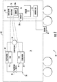
Figure 1 schematically illustrates a refrigeration system designed according to an embodiment of this invention. -
Figure 2 is a flowchart diagram summarizing an example method of monitoring a refrigeration system designed according to an embodiment of this invention. - Embodiments of this invention facilitate monitoring the generator of a refrigeration system to provide enhanced control over the function of the system. Monitoring a generator according to an embodiment of this invention facilitates detecting or predicting whether the generator is performing properly to provide optimum refrigeration system performance. When an undesired generator condition, such as winding temperature, exists, control over the refrigeration system operation allows for achieving the desired condition.
-
Figure 1 schematically illustrates arefrigeration system 20. In the illustrated example, therefrigeration system 20 is a transport refrigeration system. The illustrated example includes atransport container 22, which may be a railway car or truck trailer, for example. Theexample transport container 22 includes a temperature controlledportion 24 and anengine compartment 26. - A
cooling apparatus 30 provides refrigeration or air conditioning to the temperature controlledcompartment 24. Theexample cooling apparatus 30 includes acompressor 32 that delivers refrigerant to acondenser 34. Afan 36 associated with thecondenser 34 causes airflow across thecondenser 34, which in an air conditioning mode removes heat from the refrigerant in thecondenser 34. Ametering device 38, such as an expansion valve, is situated between thecondenser 34 and anevaporator 40. Afan 42 associated with the evaporator directs air over theevaporator 40 and into the temperature controlledcompartment 24. Thecooling apparatus 30 is schematically illustrated for discussion purposes and embodiments of this invention are not limited to any particular cooling apparatus configuration. Those skilled in the art who have the benefit of this description will understand how the components of thecooling apparatus 30 are situated relative to the temperature controlledcompartment 24 to have the desired cooling effect and will be able to select a cooling apparatus arrangement that meets their particular needs. - A
generator 50 provides electrical power to the electrically operated components of thecooling apparatus 30, such as thecompressor 32 and thefans engine 52 provides mechanical power to thegenerator 50. Theengine 52 in some embodiments is an internal combustion engine, which may operate on diesel fuel. Aprocessor 54, which includes a computing device and associated memory, monitors operation of thegenerator 50 to detect any existing or potential malfunction of thegenerator 50 that might adversely affect the operation of therefrigeration system 20. In the illustrated example, theprocessor 54 utilizes information indicative of a temperature ofwindings 56 of thegenerator 50 to determine an operating condition of thegenerator 50. - In the illustrated example, a temperature sensor 58 is situated within the
compartment 26 and provides an indication of a temperature of thewindings 56. The sensor 58 in the illustrated example includes afirst temperature sensor 58a, such as a thermistor, on thewindings 56 or otherwise within thegenerator 50 where thesensor 58a can detect the temperature of the windings. Thefirst temperature sensor 58a provides an indication of the temperature of thewindings 56 to theprocessor 54. The illustrated example includes asecond temperature sensor 58b within theengine compartment 26. Thesecond temperature sensor 58b is in the vicinity of at least one of thegenerator 50 and theengine 52 and, while not directly measuring the temperature of thegenerator windings 56, provides an indication of a corresponding temperature of thosewindings 56 to theprocessor 54. - Another
temperature sensor 60 is situated to provide information to theprocessor 54 regarding an ambient temperature in the vicinity of therefrigeration system 20. The ambient temperature has an effect on the temperature detected by the sensor 58 at least because the ambient temperature affects a temperature within thecompartment 26 and an operating temperature of theengine 52. - The
processor 54 is also configured to determine a load of thegenerator 50. In some embodiments, theprocessor 54 uses known techniques based on voltage and current associated with thegenerator 50 to determine the generator load. - The
processor 54 has access to predetermined relationship information regarding a relationship between the ambient temperature, the temperature of thegenerator windings 56 and the generator load. The load on thegenerator 50 dictates how much heat is generated in thewindings 56. In some embodiments, such information is stored in the memory of theprocessor 54. In other embodiments, theprocessor 54 accesses such information from a remote memory or database using known communication techniques. -
Figure 2 includes a flowchart diagram 70 that summarizes an example method of monitoring thegenerator 50 of therefrigeration system 20. At 72, theprocessor 54 utilizes information from thesensor 60 to determine the ambient temperature. At 74, theprocessor 54 determines the load of thegenerator 50, which will depend in part on the operation of thecooling apparatus 30. Theprocessor 54 also determines a temperature of thegenerator 50 at 76. This temperature determination is based on information from at least one of thesensors windings 56 as indicated by thesensor 58a. - At 78, the
processor 54 determines whether the temperature of thegenerator 50 exceeds a threshold, which is dependent on the ambient temperature and the load of thegenerator 50.Processor 54 utilizes the predetermined relationship among the ambient temperature, generator load and generator temperature to determine the threshold appropriate for the monitored operating conditions. The predetermined relationship information includes different thresholds for different combinations of temperature and load conditions. For example, a particular generator load may have an associated generator temperature that is acceptable for a first ambient temperature but is considered too high for a second, lower ambient temperature. When the ambient temperature is higher, the expected or acceptable generator temperature may also be higher under some conditions. In some embodiments, empirical data is collected as baseline data to define or establish the relationship between generator winding temperatures, generator loads and ambient temperatures for setting or selecting thresholds that are useful for providing an indication of acceptable or satisfactory generator performance. - In the event that the determined temperature of the generator exceeds the appropriate threshold, the
processor 54 provides an output indicating that thegenerator 50 is or may soon be operating in an undesired or less than optimum manner. In some cases the output of theprocessor 54 includes a warning or alarm indicating that thegenerator 50 requires service. In some embodiments, the thresholds are selected to result in an output from theprocessor 54 that indicates when preventative maintenance would be useful for improve generator reliability and the useful life of thegenerator 50. - In some embodiments the
processor 54 controls operation of therefrigeration system 20 in a manner that will permit the generator winding temperature to decrease. For example, theprocessor 54 will cause thecooling apparatus 30 of therefrigeration system 20 to operate in a manner that places a lower load on thegenerator 50, which will allow the winding temperature to decrease. Theprocessor 54 in some examples repeatedly or continuously monitors the temperature of thegenerator 50 until the temperature returns to a level below the threshold and then returns the operation of thecooling apparatus 30 to the state of operation that existed prior to the generator temperature exceeding the threshold. - The generator monitoring and refrigeration system control of the disclosed example embodiment enhances the overall function of the
refrigeration system 20 by providing enhanced control over the operating condition of thegenerator 50, which is necessary for providing adequate electrical power to the components of thecooling apparatus 30. - The preceding description is exemplary rather than limiting in nature. Variations and modifications to the disclosed examples may become apparent to those skilled in the art that do not necessarily depart from the essence of this invention. The scope of legal protection given to this invention can only be determined by studying the following claims.
Claims (15)
- A refrigeration system (20), comprising:a cooling apparatus (30);a generator (50) that provides electrical power to the cooling apparatus (30);an engine (52) that provides mechanical power to the generator (50); anda processor (54) configured to
determine an ambient temperature,
determine a load of the generator (50),
determine a temperature of the generator (50), and
determine whether the temperature of the generator (50) exceeds a threshold, wherein the threshold is dependent on the ambient temperature and the load of the generator (50). - The refrigeration system of claim 1, comprising at least one temperature sensor (58a, 58b) that provides an indication of the temperature of the generator (50) to the processor.
- The refrigeration system of claim 2, comprising a compartment (26) containing the generator (50) and the engine (52) and wherein the temperature sensor (58b) is situated in the compartment (26).
- The refrigeration system of claims 2 or 3, wherein the temperature sensor (58a) is situated in or on the generator (50) and provides an indication of the temperature of windings (56) of the generator (50).
- The refrigeration system of any preceding claim, wherein the determined temperature of the generator (50) is indicative of a temperature of windings (56) of the generator (50).
- The refrigeration system of any preceding claim, wherein the processor (54) is configured to provide an output when the temperature of the generator (50) exceeds the threshold,
and/or wherein the threshold is based on a predetermined relationship between ambient temperature, generator load and generator temperature. - The refrigeration system of any preceding claim, wherein the processor (54) is configured to control at least the cooling apparatus (30) in a manner that alters a load on the generator (50) when the determined temperature of the generator (50) exceeds the threshold,
optionally wherein the processor (54) is configured to alter operation of the cooling apparatus (30) to reduce the load on the generator (50). - A transport container (22) comprising the refrigeration system (20) of any preceding claim, wherein
the cooling apparatus (30) is configured to control a temperature in the transport container (22); and
the engine (52) and the generator (50) are supported for movement with the transport container (22). - A method of monitoring a refrigeration system (20) that includes a cooling apparatus (30), a generator (50) that provides electrical power to the cooling apparatus (30) and an engine (52) that provides power to the generator (50), the method comprising using a processor (54) for:determining an ambient temperature;determining a load of the generator (50);determining a temperature of the generator (50); anddetermining whether the temperature of the generator (50) exceeds a threshold, wherein the threshold is dependent on the ambient temperature and the load of the generator (50).
- The method of claim 9, comprising using at least one temperature sensor (58a, 58b) to obtain an indication of the temperature of the generator (50).
- The method of claim 10, wherein the temperature sensor (58b) is situated in a compartment (26) containing the generator (50) and the engine (52).
- The method of claim 10 or 11, wherein the temperature sensor (58a) is situated in or on the generator (50) and provides an indication of the temperature of windings (56) of the generator (50).
- The method of any of claims 9 to 12, wherein the determined temperature of the generator (50) is indicative of a temperature of windings (56) of the generator (50).
- The method of any of claims 9 to 13, comprising providing an output when the temperature of the generator (50) exceeds the threshold,
and/or wherein the threshold is based on a predetermined relationship between ambient temperature, generator load and generator temperature. - The method of any of claims 9 to 14, comprising controlling at least the cooling apparatus (30) in a manner that alters a load on the generator (50) when the determined temperature of the generator (50) exceeds the threshold,
optionally, wherein controlling at least the cooling apparatus (30) comprises altering operation of the cooling apparatus (30) to reduce the load on the generator (50).
Applications Claiming Priority (1)
| Application Number | Priority Date | Filing Date | Title |
|---|---|---|---|
| US201862643985P | 2018-03-16 | 2018-03-16 |
Publications (2)
| Publication Number | Publication Date |
|---|---|
| EP3539803A1 true EP3539803A1 (en) | 2019-09-18 |
| EP3539803B1 EP3539803B1 (en) | 2022-03-30 |
Family
ID=65635506
Family Applications (1)
| Application Number | Title | Priority Date | Filing Date |
|---|---|---|---|
| EP19159902.6A Active EP3539803B1 (en) | 2018-03-16 | 2019-02-28 | Refrigeration system generator monitoring |
Country Status (3)
| Country | Link |
|---|---|
| US (1) | US20190285325A1 (en) |
| EP (1) | EP3539803B1 (en) |
| CN (1) | CN110275109A (en) |
Families Citing this family (1)
| Publication number | Priority date | Publication date | Assignee | Title |
|---|---|---|---|---|
| CN113886371A (en) * | 2021-08-31 | 2022-01-04 | 华能澜沧江水电股份有限公司 | Monitoring method and system for air cooler of water turbine generator set |
Citations (4)
| Publication number | Priority date | Publication date | Assignee | Title |
|---|---|---|---|---|
| US20090241570A1 (en) * | 2008-03-27 | 2009-10-01 | Denso Corporation | Refrigerant cycle system |
| US20100154729A1 (en) * | 2008-12-18 | 2010-06-24 | Caterpillar Inc. | Systems and methods for controlling engine temperature |
| US20120230843A1 (en) * | 2011-03-07 | 2012-09-13 | Caterpillar Inc. | Cooling system for an electric drive machine and method |
| DE102016005981A1 (en) * | 2016-05-13 | 2017-11-16 | Liebherr-Transportation Systems Gmbh & Co. Kg | "Method for Controlling a Cooling System" |
Family Cites Families (2)
| Publication number | Priority date | Publication date | Assignee | Title |
|---|---|---|---|---|
| US9019108B2 (en) * | 2010-08-05 | 2015-04-28 | General Electric Company | Thermal measurement system for fault detection within a power generation system |
| WO2013170014A1 (en) * | 2012-05-09 | 2013-11-14 | Thermo King Corporation | Remote monitoring of a transport refrigeration system |
-
2019
- 2019-02-11 US US16/272,294 patent/US20190285325A1/en not_active Abandoned
- 2019-02-28 EP EP19159902.6A patent/EP3539803B1/en active Active
- 2019-03-15 CN CN201910197726.1A patent/CN110275109A/en active Pending
Patent Citations (4)
| Publication number | Priority date | Publication date | Assignee | Title |
|---|---|---|---|---|
| US20090241570A1 (en) * | 2008-03-27 | 2009-10-01 | Denso Corporation | Refrigerant cycle system |
| US20100154729A1 (en) * | 2008-12-18 | 2010-06-24 | Caterpillar Inc. | Systems and methods for controlling engine temperature |
| US20120230843A1 (en) * | 2011-03-07 | 2012-09-13 | Caterpillar Inc. | Cooling system for an electric drive machine and method |
| DE102016005981A1 (en) * | 2016-05-13 | 2017-11-16 | Liebherr-Transportation Systems Gmbh & Co. Kg | "Method for Controlling a Cooling System" |
Also Published As
| Publication number | Publication date |
|---|---|
| CN110275109A (en) | 2019-09-24 |
| EP3539803B1 (en) | 2022-03-30 |
| US20190285325A1 (en) | 2019-09-19 |
Similar Documents
| Publication | Publication Date | Title |
|---|---|---|
| CN110962535B (en) | Climate control system and method for monitoring and displaying energy usage and energy cost thereof | |
| US10562372B2 (en) | Systems and methods for starting-up a vehicular air-conditioning system | |
| CN113015641B (en) | Heated gas detector | |
| EP1038703A2 (en) | Voltage control using engine speed | |
| CA2974750A1 (en) | Mobile hybrid electric refrigeration system | |
| US20160131605A1 (en) | Method and system for predicting remaining useful life of transport units | |
| WO2010007448A1 (en) | Automatic refrigerant leak detection system of indirect means for use on cooling and refrigeration units installed on vehicles and other transportation means. | |
| JP2004226061A (en) | Temperature control using infrared detection | |
| US12499377B2 (en) | System and method to detect symptoms of impending climate control failures of transport climate control systems | |
| EP3539803B1 (en) | Refrigeration system generator monitoring | |
| US20070294005A1 (en) | Device And Method For Monitoring The Filling Level Of A Coolant Circuit Of A Vehicle Air Conditioning System | |
| CN112776603B (en) | Power and fault management of electrical components in transportation climate control systems powered by electric vehicles | |
| EP4067134A1 (en) | Transport climate control remote management | |
| EP3303949B1 (en) | Cargo-neutral diagnostic system, climate controlled mobile cargo container having a cargo-neutral diagnostic system and method | |
| KR100957159B1 (en) | Diagnosis Device and Method of Air Conditioning System of Vehicle | |
| US20200384825A1 (en) | Transportation vehicle climate control unit with air contaminant detection | |
| US10696138B2 (en) | Control apparatus and method for compressor of vehicle | |
| EP3704427B1 (en) | Transport refrigeration system and method for controlling the same | |
| KR102152080B1 (en) | Monitoring apparatus for a cooling apparatus | |
| US20190101313A1 (en) | Vehicular air conditioning systems | |
| Zima et al. | Improving the fuel efficiency of mobile A/C systems with variable displacement compressors | |
| WO2015027232A1 (en) | System and method for controlling air conditioning system | |
| KR20100081438A (en) | Method of controlling vehicle's fan speed | |
| KR20150011053A (en) | Railway vehicle operation-control system |
Legal Events
| Date | Code | Title | Description |
|---|---|---|---|
| PUAI | Public reference made under article 153(3) epc to a published international application that has entered the european phase |
Free format text: ORIGINAL CODE: 0009012 |
|
| STAA | Information on the status of an ep patent application or granted ep patent |
Free format text: STATUS: THE APPLICATION HAS BEEN PUBLISHED |
|
| AK | Designated contracting states |
Kind code of ref document: A1 Designated state(s): AL AT BE BG CH CY CZ DE DK EE ES FI FR GB GR HR HU IE IS IT LI LT LU LV MC MK MT NL NO PL PT RO RS SE SI SK SM TR |
|
| AX | Request for extension of the european patent |
Extension state: BA ME |
|
| STAA | Information on the status of an ep patent application or granted ep patent |
Free format text: STATUS: REQUEST FOR EXAMINATION WAS MADE |
|
| 17P | Request for examination filed |
Effective date: 20200318 |
|
| RBV | Designated contracting states (corrected) |
Designated state(s): AL AT BE BG CH CY CZ DE DK EE ES FI FR GB GR HR HU IE IS IT LI LT LU LV MC MK MT NL NO PL PT RO RS SE SI SK SM TR |
|
| R17P | Request for examination filed (corrected) |
Effective date: 20200318 |
|
| GRAP | Despatch of communication of intention to grant a patent |
Free format text: ORIGINAL CODE: EPIDOSNIGR1 |
|
| STAA | Information on the status of an ep patent application or granted ep patent |
Free format text: STATUS: GRANT OF PATENT IS INTENDED |
|
| RIC1 | Information provided on ipc code assigned before grant |
Ipc: B60H 1/00 20060101AFI20210519BHEP Ipc: B60H 1/32 20060101ALI20210519BHEP Ipc: F25D 11/00 20060101ALN20210519BHEP |
|
| INTG | Intention to grant announced |
Effective date: 20210615 |
|
| GRAJ | Information related to disapproval of communication of intention to grant by the applicant or resumption of examination proceedings by the epo deleted |
Free format text: ORIGINAL CODE: EPIDOSDIGR1 |
|
| STAA | Information on the status of an ep patent application or granted ep patent |
Free format text: STATUS: REQUEST FOR EXAMINATION WAS MADE |
|
| INTC | Intention to grant announced (deleted) | ||
| RIC1 | Information provided on ipc code assigned before grant |
Ipc: F25D 11/00 20060101ALN20211123BHEP Ipc: B60H 1/32 20060101ALI20211123BHEP Ipc: B60H 1/00 20060101AFI20211123BHEP |
|
| GRAP | Despatch of communication of intention to grant a patent |
Free format text: ORIGINAL CODE: EPIDOSNIGR1 |
|
| STAA | Information on the status of an ep patent application or granted ep patent |
Free format text: STATUS: GRANT OF PATENT IS INTENDED |
|
| INTG | Intention to grant announced |
Effective date: 20220104 |
|
| GRAS | Grant fee paid |
Free format text: ORIGINAL CODE: EPIDOSNIGR3 |
|
| GRAA | (expected) grant |
Free format text: ORIGINAL CODE: 0009210 |
|
| STAA | Information on the status of an ep patent application or granted ep patent |
Free format text: STATUS: THE PATENT HAS BEEN GRANTED |
|
| AK | Designated contracting states |
Kind code of ref document: B1 Designated state(s): AL AT BE BG CH CY CZ DE DK EE ES FI FR GB GR HR HU IE IS IT LI LT LU LV MC MK MT NL NO PL PT RO RS SE SI SK SM TR |
|
| REG | Reference to a national code |
Ref country code: GB Ref legal event code: FG4D |
|
| REG | Reference to a national code |
Ref country code: CH Ref legal event code: EP |
|
| REG | Reference to a national code |
Ref country code: AT Ref legal event code: REF Ref document number: 1478860 Country of ref document: AT Kind code of ref document: T Effective date: 20220415 |
|
| REG | Reference to a national code |
Ref country code: DE Ref legal event code: R096 Ref document number: 602019012933 Country of ref document: DE |
|
| REG | Reference to a national code |
Ref country code: IE Ref legal event code: FG4D |
|
| REG | Reference to a national code |
Ref country code: NL Ref legal event code: FP |
|
| REG | Reference to a national code |
Ref country code: LT Ref legal event code: MG9D |
|
| PG25 | Lapsed in a contracting state [announced via postgrant information from national office to epo] |
Ref country code: SE Free format text: LAPSE BECAUSE OF FAILURE TO SUBMIT A TRANSLATION OF THE DESCRIPTION OR TO PAY THE FEE WITHIN THE PRESCRIBED TIME-LIMIT Effective date: 20220330 Ref country code: RS Free format text: LAPSE BECAUSE OF FAILURE TO SUBMIT A TRANSLATION OF THE DESCRIPTION OR TO PAY THE FEE WITHIN THE PRESCRIBED TIME-LIMIT Effective date: 20220330 Ref country code: NO Free format text: LAPSE BECAUSE OF FAILURE TO SUBMIT A TRANSLATION OF THE DESCRIPTION OR TO PAY THE FEE WITHIN THE PRESCRIBED TIME-LIMIT Effective date: 20220630 Ref country code: LT Free format text: LAPSE BECAUSE OF FAILURE TO SUBMIT A TRANSLATION OF THE DESCRIPTION OR TO PAY THE FEE WITHIN THE PRESCRIBED TIME-LIMIT Effective date: 20220330 Ref country code: HR Free format text: LAPSE BECAUSE OF FAILURE TO SUBMIT A TRANSLATION OF THE DESCRIPTION OR TO PAY THE FEE WITHIN THE PRESCRIBED TIME-LIMIT Effective date: 20220330 Ref country code: BG Free format text: LAPSE BECAUSE OF FAILURE TO SUBMIT A TRANSLATION OF THE DESCRIPTION OR TO PAY THE FEE WITHIN THE PRESCRIBED TIME-LIMIT Effective date: 20220630 |
|
| REG | Reference to a national code |
Ref country code: AT Ref legal event code: MK05 Ref document number: 1478860 Country of ref document: AT Kind code of ref document: T Effective date: 20220330 |
|
| PG25 | Lapsed in a contracting state [announced via postgrant information from national office to epo] |
Ref country code: LV Free format text: LAPSE BECAUSE OF FAILURE TO SUBMIT A TRANSLATION OF THE DESCRIPTION OR TO PAY THE FEE WITHIN THE PRESCRIBED TIME-LIMIT Effective date: 20220330 Ref country code: GR Free format text: LAPSE BECAUSE OF FAILURE TO SUBMIT A TRANSLATION OF THE DESCRIPTION OR TO PAY THE FEE WITHIN THE PRESCRIBED TIME-LIMIT Effective date: 20220701 Ref country code: FI Free format text: LAPSE BECAUSE OF FAILURE TO SUBMIT A TRANSLATION OF THE DESCRIPTION OR TO PAY THE FEE WITHIN THE PRESCRIBED TIME-LIMIT Effective date: 20220330 |
|
| PG25 | Lapsed in a contracting state [announced via postgrant information from national office to epo] |
Ref country code: SM Free format text: LAPSE BECAUSE OF FAILURE TO SUBMIT A TRANSLATION OF THE DESCRIPTION OR TO PAY THE FEE WITHIN THE PRESCRIBED TIME-LIMIT Effective date: 20220330 Ref country code: SK Free format text: LAPSE BECAUSE OF FAILURE TO SUBMIT A TRANSLATION OF THE DESCRIPTION OR TO PAY THE FEE WITHIN THE PRESCRIBED TIME-LIMIT Effective date: 20220330 Ref country code: RO Free format text: LAPSE BECAUSE OF FAILURE TO SUBMIT A TRANSLATION OF THE DESCRIPTION OR TO PAY THE FEE WITHIN THE PRESCRIBED TIME-LIMIT Effective date: 20220330 Ref country code: PT Free format text: LAPSE BECAUSE OF FAILURE TO SUBMIT A TRANSLATION OF THE DESCRIPTION OR TO PAY THE FEE WITHIN THE PRESCRIBED TIME-LIMIT Effective date: 20220801 Ref country code: ES Free format text: LAPSE BECAUSE OF FAILURE TO SUBMIT A TRANSLATION OF THE DESCRIPTION OR TO PAY THE FEE WITHIN THE PRESCRIBED TIME-LIMIT Effective date: 20220330 Ref country code: EE Free format text: LAPSE BECAUSE OF FAILURE TO SUBMIT A TRANSLATION OF THE DESCRIPTION OR TO PAY THE FEE WITHIN THE PRESCRIBED TIME-LIMIT Effective date: 20220330 Ref country code: CZ Free format text: LAPSE BECAUSE OF FAILURE TO SUBMIT A TRANSLATION OF THE DESCRIPTION OR TO PAY THE FEE WITHIN THE PRESCRIBED TIME-LIMIT Effective date: 20220330 Ref country code: AT Free format text: LAPSE BECAUSE OF FAILURE TO SUBMIT A TRANSLATION OF THE DESCRIPTION OR TO PAY THE FEE WITHIN THE PRESCRIBED TIME-LIMIT Effective date: 20220330 |
|
| PG25 | Lapsed in a contracting state [announced via postgrant information from national office to epo] |
Ref country code: PL Free format text: LAPSE BECAUSE OF FAILURE TO SUBMIT A TRANSLATION OF THE DESCRIPTION OR TO PAY THE FEE WITHIN THE PRESCRIBED TIME-LIMIT Effective date: 20220330 Ref country code: IS Free format text: LAPSE BECAUSE OF FAILURE TO SUBMIT A TRANSLATION OF THE DESCRIPTION OR TO PAY THE FEE WITHIN THE PRESCRIBED TIME-LIMIT Effective date: 20220730 Ref country code: AL Free format text: LAPSE BECAUSE OF FAILURE TO SUBMIT A TRANSLATION OF THE DESCRIPTION OR TO PAY THE FEE WITHIN THE PRESCRIBED TIME-LIMIT Effective date: 20220330 |
|
| REG | Reference to a national code |
Ref country code: DE Ref legal event code: R097 Ref document number: 602019012933 Country of ref document: DE |
|
| PG25 | Lapsed in a contracting state [announced via postgrant information from national office to epo] |
Ref country code: DK Free format text: LAPSE BECAUSE OF FAILURE TO SUBMIT A TRANSLATION OF THE DESCRIPTION OR TO PAY THE FEE WITHIN THE PRESCRIBED TIME-LIMIT Effective date: 20220330 |
|
| PLBE | No opposition filed within time limit |
Free format text: ORIGINAL CODE: 0009261 |
|
| STAA | Information on the status of an ep patent application or granted ep patent |
Free format text: STATUS: NO OPPOSITION FILED WITHIN TIME LIMIT |
|
| 26N | No opposition filed |
Effective date: 20230103 |
|
| PG25 | Lapsed in a contracting state [announced via postgrant information from national office to epo] |
Ref country code: SI Free format text: LAPSE BECAUSE OF FAILURE TO SUBMIT A TRANSLATION OF THE DESCRIPTION OR TO PAY THE FEE WITHIN THE PRESCRIBED TIME-LIMIT Effective date: 20220330 |
|
| PG25 | Lapsed in a contracting state [announced via postgrant information from national office to epo] |
Ref country code: IT Free format text: LAPSE BECAUSE OF FAILURE TO SUBMIT A TRANSLATION OF THE DESCRIPTION OR TO PAY THE FEE WITHIN THE PRESCRIBED TIME-LIMIT Effective date: 20220330 |
|
| PG25 | Lapsed in a contracting state [announced via postgrant information from national office to epo] |
Ref country code: MC Free format text: LAPSE BECAUSE OF FAILURE TO SUBMIT A TRANSLATION OF THE DESCRIPTION OR TO PAY THE FEE WITHIN THE PRESCRIBED TIME-LIMIT Effective date: 20220330 |
|
| REG | Reference to a national code |
Ref country code: CH Ref legal event code: PL |
|
| REG | Reference to a national code |
Ref country code: BE Ref legal event code: MM Effective date: 20230228 |
|
| PG25 | Lapsed in a contracting state [announced via postgrant information from national office to epo] |
Ref country code: LU Free format text: LAPSE BECAUSE OF NON-PAYMENT OF DUE FEES Effective date: 20230228 Ref country code: LI Free format text: LAPSE BECAUSE OF NON-PAYMENT OF DUE FEES Effective date: 20230228 Ref country code: CH Free format text: LAPSE BECAUSE OF NON-PAYMENT OF DUE FEES Effective date: 20230228 |
|
| REG | Reference to a national code |
Ref country code: IE Ref legal event code: MM4A |
|
| PG25 | Lapsed in a contracting state [announced via postgrant information from national office to epo] |
Ref country code: IE Free format text: LAPSE BECAUSE OF NON-PAYMENT OF DUE FEES Effective date: 20230228 |
|
| PG25 | Lapsed in a contracting state [announced via postgrant information from national office to epo] |
Ref country code: BE Free format text: LAPSE BECAUSE OF NON-PAYMENT OF DUE FEES Effective date: 20230228 |
|
| PGFP | Annual fee paid to national office [announced via postgrant information from national office to epo] |
Ref country code: NL Payment date: 20250121 Year of fee payment: 7 |
|
| PG25 | Lapsed in a contracting state [announced via postgrant information from national office to epo] |
Ref country code: CY Free format text: LAPSE BECAUSE OF FAILURE TO SUBMIT A TRANSLATION OF THE DESCRIPTION OR TO PAY THE FEE WITHIN THE PRESCRIBED TIME-LIMIT; INVALID AB INITIO Effective date: 20190228 |
|
| PG25 | Lapsed in a contracting state [announced via postgrant information from national office to epo] |
Ref country code: HU Free format text: LAPSE BECAUSE OF FAILURE TO SUBMIT A TRANSLATION OF THE DESCRIPTION OR TO PAY THE FEE WITHIN THE PRESCRIBED TIME-LIMIT; INVALID AB INITIO Effective date: 20190228 |
|
| PG25 | Lapsed in a contracting state [announced via postgrant information from national office to epo] |
Ref country code: TR Free format text: LAPSE BECAUSE OF FAILURE TO SUBMIT A TRANSLATION OF THE DESCRIPTION OR TO PAY THE FEE WITHIN THE PRESCRIBED TIME-LIMIT Effective date: 20220330 |
|
| PGFP | Annual fee paid to national office [announced via postgrant information from national office to epo] |
Ref country code: GB Payment date: 20260121 Year of fee payment: 8 |
|
| PGFP | Annual fee paid to national office [announced via postgrant information from national office to epo] |
Ref country code: DE Payment date: 20260121 Year of fee payment: 8 |
|
| PGFP | Annual fee paid to national office [announced via postgrant information from national office to epo] |
Ref country code: FR Payment date: 20260121 Year of fee payment: 8 |