EP3539723A1 - Cable staple tool assembly with a self-adjusting cable guide - Google Patents
Cable staple tool assembly with a self-adjusting cable guide Download PDFInfo
- Publication number
- EP3539723A1 EP3539723A1 EP19152412.3A EP19152412A EP3539723A1 EP 3539723 A1 EP3539723 A1 EP 3539723A1 EP 19152412 A EP19152412 A EP 19152412A EP 3539723 A1 EP3539723 A1 EP 3539723A1
- Authority
- EP
- European Patent Office
- Prior art keywords
- guide
- self
- cable
- cable guide
- adjusting
- Prior art date
- Legal status (The legal status is an assumption and is not a legal conclusion. Google has not performed a legal analysis and makes no representation as to the accuracy of the status listed.)
- Granted
Links
Images




Classifications
-
- B—PERFORMING OPERATIONS; TRANSPORTING
- B25—HAND TOOLS; PORTABLE POWER-DRIVEN TOOLS; MANIPULATORS
- B25C—HAND-HELD NAILING OR STAPLING TOOLS; MANUALLY OPERATED PORTABLE STAPLING TOOLS
- B25C5/00—Manually operated portable stapling tools; Hand-held power-operated stapling tools; Staple feeding devices therefor
- B25C5/06—Manually operated portable stapling tools; Hand-held power-operated stapling tools; Staple feeding devices therefor without provision for bending the ends of the staples on to the work
-
- B—PERFORMING OPERATIONS; TRANSPORTING
- B25—HAND TOOLS; PORTABLE POWER-DRIVEN TOOLS; MANIPULATORS
- B25C—HAND-HELD NAILING OR STAPLING TOOLS; MANUALLY OPERATED PORTABLE STAPLING TOOLS
- B25C7/00—Accessories for nailing or stapling tools, e.g. supports
-
- B—PERFORMING OPERATIONS; TRANSPORTING
- B25—HAND TOOLS; PORTABLE POWER-DRIVEN TOOLS; MANIPULATORS
- B25C—HAND-HELD NAILING OR STAPLING TOOLS; MANUALLY OPERATED PORTABLE STAPLING TOOLS
- B25C5/00—Manually operated portable stapling tools; Hand-held power-operated stapling tools; Staple feeding devices therefor
- B25C5/10—Driving means
-
- H—ELECTRICITY
- H02—GENERATION; CONVERSION OR DISTRIBUTION OF ELECTRIC POWER
- H02G—INSTALLATION OF ELECTRIC CABLES OR LINES, OR OF COMBINED OPTICAL AND ELECTRIC CABLES OR LINES
- H02G1/00—Methods or apparatus specially adapted for installing, maintaining, repairing or dismantling electric cables or lines
- H02G1/06—Methods or apparatus specially adapted for installing, maintaining, repairing or dismantling electric cables or lines for laying cables, e.g. laying apparatus on vehicle
Definitions
- the present disclosure relates to a cable staple tool assembly including a cable guide.
- Cable staple tools are used in stapling tubes or electrical cables to a workpiece, such as a wooden two-by-four.
- the nosepiece of cable staple tools can include a cable guide that is intended to assure the electrical cable is properly centered relative to the cable staple tool. This helps insure that the legs of the staple pass outside the cable so that neither leg of the staple is driven into the cable.
- Wire guides typically consist of a central recess between two guide legs.
- the height of the recess, or the length of each guide leg, of wire guides is fixed.
- the corresponding heights of electrical cables that the tool is intended to staple are variable.
- the cable guide leg length or recess height is too long for such a thin cable, then the cable guide legs will engage the workpiece before the nosepiece of the tool engages the surface of the cable. This will cause a gap between the cable and the nosepiece of the tool. This, in turn, means the staple driver will not extend far enough to drive the staple into contact with the thin cable, resulting in a cable that is not firmly secured.
- Cable staple tools can also be provided with a contact trip arm.
- a contact trip arm can operate together with the cable guide to prevent operation of the staple driving tool until the contact arm is moved from an extended, inactive position to a retracted, active position through contact with a cable positioned within the cable guide.
- the disclosed combination of self-adjusting cable guide and contact trip arm can help prevent the tool from firing until the tool is properly positioned relative to the cable as discussed hereinafter.
- a cable staple tool assembly according to claim 1 wherein optional features thereof are defined in dependent claims 2 to 8.
- a cable staple tool assembly according to claim 9 wherein optional features thereof are defined in dependent claims 10 to 15.
- a cable staple tool assembly can include a cable staple driver.
- a nosepiece assembly can define a driver channel through which the cable staple driver is driven.
- the nosepiece assembly can have a contact end.
- a self-adjusting cable guide can be coupled to the nosepiece assembly and movable between an extended guide position and a retracted guide position relative to the contact end of the nosepiece assembly.
- the self-adjusting cable guide can include a guide recess between two arms extending outwardly away from the contact end of the nosepiece assembly.
- a contact trip arm can be adjacent the self-adjusting cable guide and can have a distal end positioned to contact a cable received within a guide recess of the self-adjusting cable guide.
- the contact trip arm can be movable between an extended arm position corresponding to an inactive state of the tool and a retracted arm position corresponding to an active state of the tool.
- a cable staple tool assembly can include a cable staple driver.
- a nosepiece assembly can define a driver channel through which the cable staple driver is driven.
- the nosepiece assembly can have a contact end.
- a self-adjusting cable guide can be coupled to the nosepiece assembly and movable between an extended guide position and a retracted guide position relative to the contact end of the nosepiece assembly.
- the self-adjusting cable guide can include a guide recess between two arms extending outwardly away from the contact end of the nosepiece assembly.
- a contact trip arm can be adjacent the self-adjusting cable guide and can have a distal end positioned to contact a cable received within a guide recess of the self-adjusting cable guide.
- the contact trip arm can be movable between an extended arm position corresponding to an inactive state of the tool and a retracted arm position corresponding to an active state of the tool.
- the self-adjusting cable guide can be movable between an aligned orientation and a non-aligned orientation relative to the nosepiece assembly. When the self-adjusting cable guide is in the non-aligned orientation, cooperating misalignment stop surfaces can engage each other to stop movement of the self-adjusting cable guide toward the retracted guide position. When the self-adjusting cable guide is in the aligned orientation, the self-adjusting cable guide can be permitted to move toward the retracted guide position without engagement of the cooperating misalignment stop surface to stop movement of the self-adjusting cable guide.
- Figs. 1 - 11 illustrate one example embodiment of a cable staple tool assembly 20 of a cable staple tool 18.
- the cable staple assembly 20 can include a cable staple driver 22, and a nosepiece assembly 24 that at least partially defines a driver channel 26 through which the cable staple driver 22 is driven.
- the nosepiece assembly 24 can include a nose 28 and a nose cover 30.
- the nosepiece assembly 24 can also include a distal or contact end 32. In this example embodiment, the distal or contact end 32 of the nosepiece assembly 24 is provided by the nose 28 and the nose cover 30 defines at least a portion of the driver channel 26 of the nosepiece assembly 24.
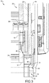
- a self-adjusting cable guide 34 is coupled to the nosepiece assembly 24 to be movable between an extended guide position (e.g., Figs. 1 and 3 ) and a retracted guide position (e.g., Figs. 2 and 4 ) relative to the distal end 32 of the nosepiece assembly 24.
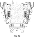
- a biasing member 42 such as the illustrated pair of laterally spaced springs, can bias the self-adjusting cable guide 34 toward the extended guide position.
- the biasing member 42 can be positioned between the nose cover 30 of the nosepiece assembly 24 and the self-adjusting cable guide 34. Referring to Figs.
- a tool housing 44 can include an outward retention surface 46, which can be provided as a detent of the tool housing 44, that engages a corresponding outward retention surface 48, which can be provided as a protrusion, of the self-adjusting cable guide 34 to retain the self-adjusting cable guide 34 to the tool 18 and preventing it from moving past the extended guide position.
- the nose cover 30 can include a main body 30b and a cover 30a that define a portion of the driver channel 26 therebetween.
- the self-adjusting cable guide 34 can include a guide recess 36 between two guide legs 38 that extend downwardly or outwardly from the distal end 32 of the nose 28 of the nosepiece assembly 24.
- the lateral distance between the pair of guide legs 38 or width "W" of the guide recess 36 is designed to accommodate corresponding lateral widths of the tubes or cables 12 that the tool 18 is intended to secure, and is positioned to protect the cables 12 from staple legs 17.
- the guide legs 38 can include distal ends 50 that can, in some cases, engage the workpiece 14.
- the guide recess 36 can include an upper surface or wall 40 extending between the guide legs 38. Such an upper wall 40 can contact a corresponding, opposing upper surface of a cable 12; at least in some situations.
- the height "H" of the legs 38 of a guide recess 36 having an upper wall 40 can be designed to be sufficient to adequately center both of a pair of stacked cables 12 in a dual stacked configuration ( Fig. 7 ) so that a staple leg 17 of a driven staple 16 will not pierce either of the dual stacked cables 12.
- a contact trip arm 52 can be positioned adjacent the self-adjusting cable guide 34 and can have a distal end 54 positioned to contact a cable 12 received within the guide recess 36 of the self-adjusting cable guide 34.
- the contact trip arm 52 can be movable between an extended arm position (e.g., Figs. 1 and 3 ) corresponding to an inactive state of the tool 18 and a retracted arm position (e.g., Figs, 2 , and 4-7 ) corresponding to an active state of the tool 18.
- the distal end 54 of the contact trip arm 52 in its retracted arm position can be at a vertical height or position that is substantially the same as the vertical height or position of the distal end 32 of the nose 28. This is because both the distal end 32 of the nose 28 and the distal end 54 of the contact trip arm 52 rests upon the cable or cables 12 when the tool 18 is ready to fire a staple 16 into workpiece 14 around the cable or cables 12.
- This same vertical height or position can also generally correspond to a position or location of the distal end 56 of the driver 22 when the driver 22 is in its terminal or extended driver position. This can insure that the driver 22 fully drives the staple 16 into the workpiece 14 and snugly up against the cable or cables 12, but without the staple 16 unduly biting into the cable or cables 12.
- the self-adjusting cable guide 34 automatically or self-adjusts for use with cables 12 of various vertical heights or thicknesses.
- the self-adjusting cable guide 34 can self-adjust or move to a first vertical position exemplified in Figs. 2 , 4 and 6 to accommodate a single cable 12 having a vertical height that is about one-half that of the height "H" of the recess 36. Even though the cable 12 does not contact the upper wall 40 of the guide recess 36 of the self-adjusting cable guide 34 in this exemplary first vertical position, both the distal end 32 of the nose 28 and the distal end 54 of the contact trip arm 52 contact the top of the cable 12.
- the distal end 32 of the nose 28 and the distal end 54 of the contact trip arm 52 are substantially vertically aligned with each other with the contact trip arm 52 in its retracted arm position, placing the tool 18 in its active state ready to drive the staple 16.
- the guide legs 38 extend along opposite sides of the cable 12 to insure proper centering of the cable 12 so that a leg 17 of a driven staple 16 will not pierce the cable 12.
- the self-adjusting cable guide 34 can automatically adjust or move to a second vertical position exemplified in Figs. 5 and 7 to accommodate, e.g., two cables 12 that each have a vertical height that can be about one-half that of the height "H" of the recess 36.
- the upper cable 12 can contact the upper wall 40 of the guide recess 36 of the self-adjusting cable guide 34.
- the self-adjusting cable guide 34 is in the second vertical position, the distal end 32 of the nose 28, the distal end 54 of the contact trip arm 52, and the upper wall 40 of the guide recess 36 can all contact the top of the upper cable 12.
- the distal end 32 of the nose 28 and the distal end 54 of the contact trip arm 52 are substantially vertically aligned with each other with the contact trip arm 52 in its retracted arm position, placing the tool 18 in its active state ready to drive the staple 16.
- the upper wall 40 of the guide recess 36 of the self-adjusting cable guide 34 can also contact the top of the upper cable 12 with the guide legs 38 extending along opposite sides of the cables 12 to insure proper centering of the cable 12, so that a staple leg 17 of a driven staple 16 will not pierce the cable 12.
- the guide recess 36 or guide leg 38 height "H” can be more than one times the height of the cables 12 that the tool is intended to staple in a dual stacked configuration.
- the guide recess 36 or guide leg 38 height "H” can be between about 1.3 and about 1.7 times a corresponding height of the cables 12 that the tool 18 and assembly 20 is intended to secure in a dual stacked configuration.
- the guide recess 36 or guide leg 38 height "H” can be between about 1.5 times a corresponding height of the cables 12 that the tool 18 and assembly 20 is intended to secure in a dual stacked configuration.
- the guide recess 36 or guide leg 38 height "H” can be between about 5 mm and about 10 mm.
- the guide recess 36 or guide leg 38 height "H” can be between about 6 mm and about 8 mm.
- the self-adjusting cable guide 34 can also help insure that the contact trip arm 52 cannot be moved to its retracted arm position, placing the tool 18 in its active state, when the cable or cables 12 are not properly centered between the guide legs 38.
- the self-adjusting cable guide 34 can be mounted for limited lateral rocking movement relative to the nose cover 30 of the nosepiece assembly 24 between an aligned orientation and a non-aligned orientation relative to the nose cover 30 of the nosepiece assembly 24.
- the self-adjusting cable guide 34 can include fault or misalignment detents or stop surfaces 58 that engage cooperating fault or misalignment detents or stop surfaces 60 of the nose cover 30 of the nosepiece assembly 24 when the self-adjusting cable guide 34 is in the non-aligned orientation to stop movement of the self-adjusting cable guide 34 toward the retracted guide position.
- the misalignment stop surfaces 58, 60 can be positioned to engage each other to stop the upper wall 40 at a vertical height that is below the vertical height of the distal end 54 of the contact trip arm 52 when the contact trip arm 52 is in its retracted arm position corresponding to the active state of the tool 18.
- the self-adjusting cable guide 34 can minimize or prevent a staple 16 from being driven when the recess 36 is misaligned with the cable 12 as a result of one the guide legs 38 being positioned on the cable 12 causing the self-adjusting cable guide 34 to move into the non-aligned orientation ( Figs. 7 and 8 ).
- the cooperating misalignment stop surfaces 58, 60 are positioned to move past each other without engaging and stopping the upward movement of the self-adjusting cable guide 34.
- the self-adjusting cable guide 34 is able to move to a vertical height that allows the distal end 54 of the contact trip arm 52 to move into its retracted position corresponding to the active state of the tool, and allowing a staple 16 to be driven by the tool 18.
- the self-adjusting cable guide 34 can include an inward stop surface 68 that is engageable with a corresponding inward stop surface 70 of the nosepiece assembly 20 to prevent the self-adjusting cable guide 36 from moving inward beyond the retracted guide position.
- the inward stop surface 70 can be provided on the nose cover 30 and can partially or completely comprise a shared common surface 70 with the misalignment stop surface 60.
- the other cooperating inward stop surface 68 can be provided on the self-adjusting cable guide 34. As with the other stop surfaces, the cooperating inward stop surfaces 68, 70 can be provided as protrusions or detents.
Landscapes
- Engineering & Computer Science (AREA)
- Mechanical Engineering (AREA)
- Portable Nailing Machines And Staplers (AREA)
Abstract
Description
- The present disclosure relates to a cable staple tool assembly including a cable guide.
- This section provides background information related to the present disclosure which is not necessarily prior art.
- Cable staple tools are used in stapling tubes or electrical cables to a workpiece, such as a wooden two-by-four. The nosepiece of cable staple tools can include a cable guide that is intended to assure the electrical cable is properly centered relative to the cable staple tool. This helps insure that the legs of the staple pass outside the cable so that neither leg of the staple is driven into the cable.
- Wire guides typically consist of a central recess between two guide legs. The height of the recess, or the length of each guide leg, of wire guides is fixed. In contrast, the corresponding heights of electrical cables that the tool is intended to staple are variable.
- For example, it is sometimes desirable to staple a single, relatively thin, low-height, cable. If the cable guide leg length or recess height is too long for such a thin cable, then the cable guide legs will engage the workpiece before the nosepiece of the tool engages the surface of the cable. This will cause a gap between the cable and the nosepiece of the tool. This, in turn, means the staple driver will not extend far enough to drive the staple into contact with the thin cable, resulting in a cable that is not firmly secured.
- In addition, it is sometimes desirable to staple two stacked cables simultaneously, resulting in a double-height cable. If the cable guide leg length, or recess height, is too short for such a stacked cable stapling situation, then the wire guide will only operate to insure the upper cable is properly centered. The cable guide legs will not be long enough to insure the lower cable is properly centered. As a result, the cable guide will not insure that one of the legs of the staple will not pierce the lower cable.
- In order to optimize the cable guide for different cable heights, a user is typically required to remove and replace one cable guide with another cable guide. It has alternatively been proposed to provide cable guides that are manually adjustable by a user between different fixed positions relative to the nosepiece of the tool. When a user does not replace the cable guide with the correct one, or does not properly adjust such manually adjustable cable guides into the proper fixed position, these proposed solutions can suffer from the same problems as those discussed above.
- Cable staple tools can also be provided with a contact trip arm. Such a contact trip arm can operate together with the cable guide to prevent operation of the staple driving tool until the contact arm is moved from an extended, inactive position to a retracted, active position through contact with a cable positioned within the cable guide. The disclosed combination of self-adjusting cable guide and contact trip arm can help prevent the tool from firing until the tool is properly positioned relative to the cable as discussed hereinafter.
- According to a first aspect of the present invention there is provided a cable staple tool assembly according to claim 1, wherein optional features thereof are defined in dependent claims 2 to 8. According to a second aspect of the present invention there is provided a cable staple tool assembly according to claim 9, wherein optional features thereof are defined in dependent claims 10 to 15.
- This section provides a general summary of the disclosure, and is not a comprehensive disclosure of its full scope or all of its features.
- In accordance with one aspect of the present disclosure, a cable staple tool assembly can include a cable staple driver. A nosepiece assembly can define a driver channel through which the cable staple driver is driven. The nosepiece assembly can have a contact end. A self-adjusting cable guide can be coupled to the nosepiece assembly and movable between an extended guide position and a retracted guide position relative to the contact end of the nosepiece assembly. The self-adjusting cable guide can include a guide recess between two arms extending outwardly away from the contact end of the nosepiece assembly. A contact trip arm can be adjacent the self-adjusting cable guide and can have a distal end positioned to contact a cable received within a guide recess of the self-adjusting cable guide. The contact trip arm can be movable between an extended arm position corresponding to an inactive state of the tool and a retracted arm position corresponding to an active state of the tool.
- In accordance with another aspect of the present disclosure, a cable staple tool assembly can include a cable staple driver. A nosepiece assembly can define a driver channel through which the cable staple driver is driven. The nosepiece assembly can have a contact end. A self-adjusting cable guide can be coupled to the nosepiece assembly and movable between an extended guide position and a retracted guide position relative to the contact end of the nosepiece assembly. The self-adjusting cable guide can include a guide recess between two arms extending outwardly away from the contact end of the nosepiece assembly. A contact trip arm can be adjacent the self-adjusting cable guide and can have a distal end positioned to contact a cable received within a guide recess of the self-adjusting cable guide. The contact trip arm can be movable between an extended arm position corresponding to an inactive state of the tool and a retracted arm position corresponding to an active state of the tool. The self-adjusting cable guide can be movable between an aligned orientation and a non-aligned orientation relative to the nosepiece assembly. When the self-adjusting cable guide is in the non-aligned orientation, cooperating misalignment stop surfaces can engage each other to stop movement of the self-adjusting cable guide toward the retracted guide position. When the self-adjusting cable guide is in the aligned orientation, the self-adjusting cable guide can be permitted to move toward the retracted guide position without engagement of the cooperating misalignment stop surface to stop movement of the self-adjusting cable guide.
- Further areas of applicability will become apparent from the description provided herein. The description and specific examples in this summary are intended for purposes of illustration only and are not intended to limit the scope of the present disclosure.
- Various aspects and embodiments of the invention will now be described by way of non-limiting example with reference to the accompanying drawings, in which.
-
Fig. 1 is an elevation view of certain components of the example cable staple tool assembly with a self-adjusting cable guide ofFigs. 3-5 in accordance with the present disclosure, with the self-adjusting cable guide and the contact trip arm in their extended positions. -
Fig. 2 is an elevation view of the components ofFig. 1 , with the self-adjusting cable guide in a single cable retracted guide position and the contact trip arm in its retracted arm position. -
Fig. 3 is a partial cross-section view of the example cable staple tool assembly, with the self-adjusting cable guide and the contact trip arm in their extended positions. -
Fig. 4 is a partial cross-section view of the example cable staple tool assembly, with the self-adjusting cable guide in a single cable retracted guide position and the contact trip arm in its retracted arm position. -
Fig. 5 is a partial cross-section view of the example cable staple tool assembly, with the self-adjusting cable guide in a double cable retracted guide position and the contact trip arm in its retracted arm position. -
Fig. 6 is an elevation view of the components ofFig. 1 of the example cable staple tool assembly, with the self-adjusting cable guide in a single cable retracted guide position and the contact trip arm in its retracted arm position, and showing a cable and workpiece. -
Fig. 7 is an elevation view of the components ofFig. 1 of the example cable staple tool assembly, with the self-adjusting cable guide in a double cable retracted guide position and the contact trip arm in its retracted arm position, and showing a cable and workpiece. -
Fig. 8 is an elevation view of the components ofFig. 1 of the example cable staple tool assembly, with the self-adjusting cable guide in a non-aligned orientation as a result of an end of one guide leg contacting the cable. -
Fig. 9 is another elevation view similar toFig. 8 . -
Fig. 10 is a partial cross-section view of the example cable staple tool assembly with a self-adjusting cable guide. -
Fig. 11 is an exploded perspective view including the self-adjusting cable guide and nose cover of the example cable staple tool assembly. - Corresponding reference numerals indicate corresponding parts throughout the several views of the drawings.
- Example embodiments will now be described more fully with reference to the accompanying drawings.
-
Figs. 1 - 11 illustrate one example embodiment of a cablestaple tool assembly 20 of acable staple tool 18. Such anassembly 20 andcable staple tool 18 are specifically designed to drive astaple 16 into aworkpiece 14 straddling a tube orelectrical cable 12 to secure thecable 12 to theworkpiece 14. Thecable staple assembly 20 can include acable staple driver 22, and anosepiece assembly 24 that at least partially defines adriver channel 26 through which thecable staple driver 22 is driven. Thenosepiece assembly 24 can include anose 28 and anose cover 30. Thenosepiece assembly 24 can also include a distal orcontact end 32. In this example embodiment, the distal or contact end 32 of thenosepiece assembly 24 is provided by thenose 28 and thenose cover 30 defines at least a portion of thedriver channel 26 of thenosepiece assembly 24. - A self-adjusting
cable guide 34 is coupled to thenosepiece assembly 24 to be movable between an extended guide position (e.g.,Figs. 1 and3 ) and a retracted guide position (e.g.,Figs. 2 and4 ) relative to thedistal end 32 of thenosepiece assembly 24. A biasingmember 42, such as the illustrated pair of laterally spaced springs, can bias the self-adjustingcable guide 34 toward the extended guide position. The biasingmember 42 can be positioned between thenose cover 30 of thenosepiece assembly 24 and the self-adjustingcable guide 34. Referring toFigs. 10 and11 , atool housing 44 can include anoutward retention surface 46, which can be provided as a detent of thetool housing 44, that engages a correspondingoutward retention surface 48, which can be provided as a protrusion, of the self-adjustingcable guide 34 to retain the self-adjustingcable guide 34 to thetool 18 and preventing it from moving past the extended guide position. In addition, thenose cover 30 can include amain body 30b and acover 30a that define a portion of thedriver channel 26 therebetween. - The self-adjusting
cable guide 34 can include aguide recess 36 between two guidelegs 38 that extend downwardly or outwardly from thedistal end 32 of thenose 28 of thenosepiece assembly 24. The lateral distance between the pair ofguide legs 38 or width "W" of theguide recess 36 is designed to accommodate corresponding lateral widths of the tubes orcables 12 that thetool 18 is intended to secure, and is positioned to protect thecables 12 fromstaple legs 17. Theguide legs 38 can include distal ends 50 that can, in some cases, engage theworkpiece 14. - As in the illustrated example, the
guide recess 36 can include an upper surface orwall 40 extending between theguide legs 38. Such anupper wall 40 can contact a corresponding, opposing upper surface of acable 12; at least in some situations. The height "H" of thelegs 38 of aguide recess 36 having anupper wall 40 can be designed to be sufficient to adequately center both of a pair of stackedcables 12 in a dual stacked configuration (Fig. 7 ) so that astaple leg 17 of a drivenstaple 16 will not pierce either of the dualstacked cables 12. - A
contact trip arm 52 can be positioned adjacent the self-adjustingcable guide 34 and can have adistal end 54 positioned to contact acable 12 received within theguide recess 36 of the self-adjustingcable guide 34. Thecontact trip arm 52 can be movable between an extended arm position (e.g.,Figs. 1 and3 ) corresponding to an inactive state of thetool 18 and a retracted arm position (e.g.,Figs, 2 , and4-7 ) corresponding to an active state of thetool 18. As shown inFigs. 4 and5 , thedistal end 54 of thecontact trip arm 52 in its retracted arm position can be at a vertical height or position that is substantially the same as the vertical height or position of thedistal end 32 of thenose 28. This is because both thedistal end 32 of thenose 28 and thedistal end 54 of thecontact trip arm 52 rests upon the cable orcables 12 when thetool 18 is ready to fire a staple 16 intoworkpiece 14 around the cable orcables 12. - This same vertical height or position can also generally correspond to a position or location of the
distal end 56 of thedriver 22 when thedriver 22 is in its terminal or extended driver position. This can insure that thedriver 22 fully drives the staple 16 into theworkpiece 14 and snugly up against the cable orcables 12, but without the staple 16 unduly biting into the cable orcables 12. - The self-adjusting
cable guide 34 automatically or self-adjusts for use withcables 12 of various vertical heights or thicknesses. The self-adjustingcable guide 34 can self-adjust or move to a first vertical position exemplified inFigs. 2 ,4 and6 to accommodate asingle cable 12 having a vertical height that is about one-half that of the height "H" of therecess 36. Even though thecable 12 does not contact theupper wall 40 of theguide recess 36 of the self-adjustingcable guide 34 in this exemplary first vertical position, both thedistal end 32 of thenose 28 and thedistal end 54 of thecontact trip arm 52 contact the top of thecable 12. Thus, thedistal end 32 of thenose 28 and thedistal end 54 of thecontact trip arm 52 are substantially vertically aligned with each other with thecontact trip arm 52 in its retracted arm position, placing thetool 18 in its active state ready to drive thestaple 16. In addition, theguide legs 38 extend along opposite sides of thecable 12 to insure proper centering of thecable 12 so that aleg 17 of a drivenstaple 16 will not pierce thecable 12. - The self-adjusting
cable guide 34 can automatically adjust or move to a second vertical position exemplified inFigs. 5 and7 to accommodate, e.g., twocables 12 that each have a vertical height that can be about one-half that of the height "H" of therecess 36. In this exemplary second vertical position, theupper cable 12 can contact theupper wall 40 of theguide recess 36 of the self-adjustingcable guide 34. When the self-adjustingcable guide 34 is in the second vertical position, thedistal end 32 of thenose 28, thedistal end 54 of thecontact trip arm 52, and theupper wall 40 of theguide recess 36 can all contact the top of theupper cable 12. - In the second vertical position (like the first vertical position), the
distal end 32 of thenose 28 and thedistal end 54 of thecontact trip arm 52 are substantially vertically aligned with each other with thecontact trip arm 52 in its retracted arm position, placing thetool 18 in its active state ready to drive thestaple 16. In addition, theupper wall 40 of theguide recess 36 of the self-adjustingcable guide 34 can also contact the top of theupper cable 12 with theguide legs 38 extending along opposite sides of thecables 12 to insure proper centering of thecable 12, so that astaple leg 17 of a drivenstaple 16 will not pierce thecable 12. In cases where a height "H" of theguide recess 36 is greater than the overall height of the stackedcables 12, theupper wall 40 of theguide recess 36 of the self-adjustingcable guide 34 will not contact the top of theupper cable 12. In cases where a height "H" of theguide recess 36 is less than the overall height of the stackedcables 12, there can be a gap (not shown) between thedistal end 50 of theguide legs 38 and theworkpiece 14. Nevertheless, theguide legs 38 can extend sufficiently along the opposite sides of thelowermost cable 12 to insure bothcables 12 are properly centered. - For example, the
guide recess 36 or guideleg 38 height "H" can be more than one times the height of thecables 12 that the tool is intended to staple in a dual stacked configuration. In some instances, theguide recess 36 or guideleg 38 height "H" can be between about 1.3 and about 1.7 times a corresponding height of thecables 12 that thetool 18 andassembly 20 is intended to secure in a dual stacked configuration. In some instances, theguide recess 36 or guideleg 38 height "H" can be between about 1.5 times a corresponding height of thecables 12 that thetool 18 andassembly 20 is intended to secure in a dual stacked configuration. In some instances, theguide recess 36 or guideleg 38 height "H" can be between about 5 mm and about 10 mm. In some instances, theguide recess 36 or guideleg 38 height "H" can be between about 6 mm and about 8 mm. - Referring to
Figs. 8 and 9 , the self-adjustingcable guide 34 can also help insure that thecontact trip arm 52 cannot be moved to its retracted arm position, placing thetool 18 in its active state, when the cable orcables 12 are not properly centered between theguide legs 38. For example, when the cable orcables 12 contact thedistal end 50 of one of theguide legs 38, instead of passing between theguide legs 38, astaple leg 17 of a staple 16 driven from thetool 18 would pierce thecable 12. In order to avoid this, the self-adjustingcable guide 34 can be mounted for limited lateral rocking movement relative to thenose cover 30 of thenosepiece assembly 24 between an aligned orientation and a non-aligned orientation relative to thenose cover 30 of thenosepiece assembly 24. - For example, the self-adjusting
cable guide 34 can include fault or misalignment detents or stopsurfaces 58 that engage cooperating fault or misalignment detents or stopsurfaces 60 of thenose cover 30 of thenosepiece assembly 24 when the self-adjustingcable guide 34 is in the non-aligned orientation to stop movement of the self-adjustingcable guide 34 toward the retracted guide position. The misalignment stop surfaces 58, 60 can be positioned to engage each other to stop theupper wall 40 at a vertical height that is below the vertical height of thedistal end 54 of thecontact trip arm 52 when thecontact trip arm 52 is in its retracted arm position corresponding to the active state of thetool 18. Thus, the self-adjustingcable guide 34 can minimize or prevent a staple 16 from being driven when therecess 36 is misaligned with thecable 12 as a result of one theguide legs 38 being positioned on thecable 12 causing the self-adjustingcable guide 34 to move into the non-aligned orientation (Figs. 7 and8 ). - In the aligned orientation (e.g.,
Figs 6 and 7 ) when therecess 36 is properly aligned with thecable 12 and theguide legs 38 are properly positioned around the cable orcables 12, the cooperating misalignment stop surfaces 58, 60 are positioned to move past each other without engaging and stopping the upward movement of the self-adjustingcable guide 34. Thus, the self-adjustingcable guide 34 is able to move to a vertical height that allows thedistal end 54 of thecontact trip arm 52 to move into its retracted position corresponding to the active state of the tool, and allowing a staple 16 to be driven by thetool 18. - The self-adjusting
cable guide 34 can include aninward stop surface 68 that is engageable with a correspondinginward stop surface 70 of thenosepiece assembly 20 to prevent the self-adjustingcable guide 36 from moving inward beyond the retracted guide position. As in the illustrated example, theinward stop surface 70 can be provided on thenose cover 30 and can partially or completely comprise a sharedcommon surface 70 with themisalignment stop surface 60. The other cooperating inward stopsurface 68 can be provided on the self-adjustingcable guide 34. As with the other stop surfaces, the cooperating inward stop surfaces 68, 70 can be provided as protrusions or detents. - It will be appreciated that whilst various aspects and embodiments have heretofore been described, the scope of the present invention is not limited thereto and instead extends to encompass all arrangements, and modifications and alterations thereto, which fall within the scope of the appended claims.
Claims (15)
- A cable staple tool assembly comprising:a cable staple driver;a nosepiece assembly defining a driver channel through which the cable staple driver is driven, the nosepiece assembly having a contact end;a self-adjusting cable guide coupled to the nosepiece assembly and movable between an extended guide position and a retracted guide position relative to the contact end of the nosepiece assembly, the self-adjusting cable guide including a guide recess between two arms extending outwardly away from the contact end of the nosepiece assembly;a contact trip arm adjacent the self-adjusting cable guide and having a distal end positioned to contact a cable received within a guide recess of the self-adjusting cable guide, the contact trip arm being movable between an extended arm position corresponding to an inactive state of the tool and a retracted arm position corresponding to an active state of the tool.
- The cable staple tool assembly of claim 1, wherein the nosepiece assembly comprises a nose cover fixedly coupled to a nose, and the nose defines the contact end of the nosepiece assembly, optionally wherein the nose cover defines a portion of the driver channel of the nosepiece assembly.
- The cable staple tool assembly of any preceding claim, wherein a height of the guide recess is designed to correspond to between 1.3 and 1.7 times a height of a cable intended to be stapled.
- The cable staple tool assembly of any preceding claim, wherein a height of the guide recess of the self-adjusting cable guide is between about 5 mm and about 10 mm.
- The cable staple tool assembly of any preceding claim, wherein a biasing member biases the self-adjusting cable guide toward the extended guide position, optionally wherein the biasing member comprises a pair of laterally spaced springs positioned between the nosepiece assembly and the self-adjusting cable guide.
- The cable staple tool assembly of any preceding claim, wherein the self-adjusting cable guide includes an outward retention stop surface engageable with a corresponding outward retention stop surface of the nosepiece assembly to prevent the self-adjusting cable guide from moving outward beyond the extended guide position, optionally wherein the nosepiece assembly includes a housing and the corresponding outward retention stop surface is provided on the housing.
- The cable staple tool assembly of claim 6, wherein the outward stop surface of the self-adjusting cable guide is provided by a protrusion and the corresponding outward stop surface of the nosepiece assembly is provided by a detent.
- The cable staple tool assembly of any preceding claim, wherein the nosepiece assembly includes a housing and the self-adjusting cable guide includes an inward stop surface engageable with a corresponding inward stop surface of the nosepiece assembly to prevent the self-adjusting cable guide from moving inward beyond the retracted guide position.
- A cable staple tool assembly comprising:a cable staple driver;a nosepiece assembly defining a driver channel through which the cable staple driver is driven, the nosepiece assembly having contact end;a self-adjusting cable guide coupled to the nosepiece assembly and movable between an extended guide position and a retracted guide position relative to the contact end of the nosepiece assembly, the self-adjusting cable guide including a guide recess between two arms extending outwardly away from the contact end of the nosepiece assembly;a contact trip arm adjacent the self-adjusting cable guide and having a distal end positioned to contact a cable received within a guide recess of the self-adjusting cable guide, the contact trip arm being movable between an extended arm position corresponding to an inactive state of the tool and a retracted arm position corresponding to an active state of the tool;wherein the self-adjusting cable guide is movable between an aligned orientation and a non-aligned orientation relative to the nosepiece assembly, and when the self-adjusting cable guide is in the non-aligned orientation, cooperating misalignment stop surfaces engage each other to stop movement of the self-adjusting cable guide toward the retracted guide position, and when the self-adjusting cable guide is in the aligned orientation, the self-adjusting cable guide is permitted to move toward the retracted guide position without engagement of the cooperating misalignment stop surface to stop movement of the self-adjusting cable guide.
- The cable staple tool assembly of claim 9, wherein the self-adjusting cable guide is mounted for limited lateral rocking movement relative to the nosepiece assembly between the aligned orientation and the non-aligned orientation relative to the nosepiece assembly, optionally wherein the nosepiece assembly includes a housing, and wherein the cooperating misalignment surfaces comprise a first pair of laterally spaced surfaces of the self-adjusting cable guide, and the cooperating misalignment surfaces comprise a second pair of laterally spaced surfaces of the nosepiece assembly.
- The cable staple tool assembly of claim 9 or 10, wherein the nosepiece assembly includes a nose cover, and wherein the cooperating misalignment surfaces comprise a first pair of laterally spaced surfaces of the self-adjusting cable guide, and the cooperating misalignment surfaces comprise a second pair of laterally spaced surfaces of the nose cover, optionally wherein the self-adjusting cable guide is mounted for limited lateral rocking movement relative to the nosepiece assembly between the aligned orientation and the non-aligned orientation relative to the nosepiece assembly.
- The cable staple tool assembly of claim 9, wherein the cooperating misalignment stop surfaces are positioned to engage each other to stop movement of the self-adjusting cable guide at a position in which an uppermost central portion of the recess is at a vertical height that is below the vertical height of the distal end of the contact trip arm when the contact trip arm is in the retracted arm position corresponding to the active state of the tool.
- The cable staple tool assembly of claim 12, wherein the self-adjusting cable guide is mounted for limited lateral rocking movement relative to the nosepiece assembly between the aligned orientation and the non-aligned orientation relative to the nosepiece assembly.
- The cable staple tool assembly of claim 13, wherein the nosepiece assembly includes a housing, and wherein the cooperating misalignment surfaces comprise a first pair of laterally spaced surfaces of the self-adjusting cable guide, and the cooperating misalignment surfaces comprise a second pair of laterally spaced surfaces of the nosepiece assembly.
- The cable staple tool assembly of claim 13, wherein the nosepiece assembly includes a nose cover, and wherein the cooperating misalignment surfaces comprise a first pair of laterally spaced surfaces of the self-adjusting cable guide, and the cooperating misalignment surfaces comprise a second pair of laterally spaced surfaces of the nose cover.
Applications Claiming Priority (1)
| Application Number | Priority Date | Filing Date | Title |
|---|---|---|---|
| US15/876,584 US11090794B2 (en) | 2018-01-22 | 2018-01-22 | Cable staple tool assembly with a self-adjusting cable guide |
Publications (2)
| Publication Number | Publication Date |
|---|---|
| EP3539723A1 true EP3539723A1 (en) | 2019-09-18 |
| EP3539723B1 EP3539723B1 (en) | 2022-08-31 |
Family
ID=65036730
Family Applications (1)
| Application Number | Title | Priority Date | Filing Date |
|---|---|---|---|
| EP19152412.3A Active EP3539723B1 (en) | 2018-01-22 | 2019-01-17 | Cable staple tool assembly with a self-adjusting cable guide |
Country Status (2)
| Country | Link |
|---|---|
| US (1) | US11090794B2 (en) |
| EP (1) | EP3539723B1 (en) |
Families Citing this family (6)
| Publication number | Priority date | Publication date | Assignee | Title |
|---|---|---|---|---|
| TWI812797B (en) * | 2019-10-23 | 2023-08-21 | 鑽全實業股份有限公司 | Impact device of flywheel electric nail gun |
| CN212240877U (en) * | 2020-05-12 | 2020-12-29 | 杭州新星光电有限公司 | Nailing device and nailing gun comprising same |
| US12162125B2 (en) | 2020-10-30 | 2024-12-10 | Milwaukee Electric Tool Corporation | Powered fastener driver |
| EP4281253A4 (en) | 2021-01-20 | 2024-11-27 | Milwaukee Electric Tool Corporation | ELECTRIC FIXING ELEMENT DRIVE DEVICE |
| US12202112B2 (en) | 2021-01-20 | 2025-01-21 | Milwaukee Electric Tool Corporation | Powered fastener driver |
| US20220362915A1 (en) * | 2021-05-17 | 2022-11-17 | Christopher Dumph | Wire stapler |
Citations (5)
| Publication number | Priority date | Publication date | Assignee | Title |
|---|---|---|---|---|
| US4227637A (en) * | 1978-11-30 | 1980-10-14 | Haytayan Harry M | Pneumatic fastening tool |
| US4552296A (en) * | 1983-10-19 | 1985-11-12 | Wang Sheng | Stapling gun |
| US4621758A (en) * | 1985-09-13 | 1986-11-11 | Anstett Edgar P | Nailing machine |
| US20080179371A1 (en) * | 2007-01-29 | 2008-07-31 | The Halex Company | Portable fastener driving device |
| WO2015030950A1 (en) * | 2013-08-30 | 2015-03-05 | Illinois Tool Works Inc. | Staple tool |
Family Cites Families (26)
| Publication number | Priority date | Publication date | Assignee | Title |
|---|---|---|---|---|
| US2716749A (en) | 1952-02-18 | 1955-09-06 | Timmerbeil Ewald Rudolf | Stapling machine for simultaneously inserting at least two staples |
| US3198412A (en) | 1963-07-08 | 1965-08-03 | Inv S Man Corp | Magazine and safety trip for fastening device |
| US3612379A (en) * | 1965-05-24 | 1971-10-12 | Spotnails | Pneumatically operated fastener-driving machine |
| US3762620A (en) | 1972-05-15 | 1973-10-02 | Fastener Corp | Safety assembly for fastener driving tool |
| US3858781A (en) | 1973-05-14 | 1975-01-07 | Fastener Corp | Safety mechanism for fastener driving tool |
| US4087035A (en) * | 1976-12-08 | 1978-05-02 | Everette Harmon | Attachment for stapling gun |
| FR2420409A1 (en) | 1978-03-20 | 1979-10-19 | Renault | SAFETY DEVICE FOR FIXING DEVICES |
| US4380312A (en) * | 1980-07-17 | 1983-04-19 | Minnesota Mining And Manufacturing Company | Stapling tool |
| US4805824A (en) | 1985-10-01 | 1989-02-21 | Erickson Gary W | Apparatus for attaching cable to a surface |
| US5197646A (en) | 1992-03-09 | 1993-03-30 | Illinois Tool Works Inc. | Combustion-powered tool assembly |
| US5263626A (en) * | 1992-12-29 | 1993-11-23 | Illinois Tool Works Inc. | Fastener-driving tool with actuating structure biased by dual biasing means |
| US5735444A (en) | 1996-09-23 | 1998-04-07 | Arrow Fastener Co., Inc. | Insulated staple driving system |
| US5931364A (en) | 1997-06-25 | 1999-08-03 | Acme Staple Company, Inc. | Fastening tool for securing an object to a substrate |
| US5918790A (en) * | 1998-08-27 | 1999-07-06 | Donnell; Robert D. | Stapling gun adapter restraining loose linear entities |
| JP4239731B2 (en) * | 2003-07-04 | 2009-03-18 | マックス株式会社 | Contact mechanism of power driven nailer |
| US7055729B2 (en) | 2004-09-24 | 2006-06-06 | Illinois Tool Works Inc. | Tool-free depth-of-drive adjustment for a fastener-driving tool |
| TW200920562A (en) * | 2007-11-02 | 2009-05-16 | Jann Yei Industry Co Ltd | Staple gun safety device |
| TW200920567A (en) | 2007-11-15 | 2009-05-16 | Apex Mfg Co Ltd | A staple gun which is suitable for multiple types of staple nail |
| NZ587759A (en) * | 2008-03-07 | 2013-04-26 | Arrow Fastener Co Llc | Wire guide for an automatic staple gun with a substantially planar wire guide operated by a cam |
| US8042717B2 (en) * | 2009-04-13 | 2011-10-25 | Stanley Fastening Systems, Lp | Fastener driving device with contact trip having an electrical actuator |
| US8336748B2 (en) | 2009-09-15 | 2012-12-25 | Robert Bosch Gmbh | Fastener driver with driver assembly blocking member |
| JP2011088269A (en) | 2009-09-25 | 2011-05-06 | Makita Corp | Driving tool |
| US8292143B2 (en) | 2010-10-12 | 2012-10-23 | Stanley Fastening Systems, L.P. | Dry fire lockout with bypass for fastener driving device |
| US8240535B2 (en) | 2010-11-15 | 2012-08-14 | Arrow Fastener Co., Llc | Staple gun wire guide |
| US10150208B2 (en) * | 2015-10-02 | 2018-12-11 | Nailermate Enterprise Corporation | Muzzle suitable for holding nail clamps |
| CA2981019A1 (en) * | 2016-10-10 | 2018-04-10 | Power Tech Staple and Nail, Inc. | Accessory attachment for driven fastener hand tool |
-
2018
- 2018-01-22 US US15/876,584 patent/US11090794B2/en active Active
-
2019
- 2019-01-17 EP EP19152412.3A patent/EP3539723B1/en active Active
Patent Citations (5)
| Publication number | Priority date | Publication date | Assignee | Title |
|---|---|---|---|---|
| US4227637A (en) * | 1978-11-30 | 1980-10-14 | Haytayan Harry M | Pneumatic fastening tool |
| US4552296A (en) * | 1983-10-19 | 1985-11-12 | Wang Sheng | Stapling gun |
| US4621758A (en) * | 1985-09-13 | 1986-11-11 | Anstett Edgar P | Nailing machine |
| US20080179371A1 (en) * | 2007-01-29 | 2008-07-31 | The Halex Company | Portable fastener driving device |
| WO2015030950A1 (en) * | 2013-08-30 | 2015-03-05 | Illinois Tool Works Inc. | Staple tool |
Also Published As
| Publication number | Publication date |
|---|---|
| US11090794B2 (en) | 2021-08-17 |
| US20190224834A1 (en) | 2019-07-25 |
| EP3539723B1 (en) | 2022-08-31 |
Similar Documents
| Publication | Publication Date | Title |
|---|---|---|
| EP3539723B1 (en) | Cable staple tool assembly with a self-adjusting cable guide | |
| US11532918B2 (en) | Detection device and method for detecting insertion depth of terminal of cable connector | |
| US9723746B2 (en) | Slide rail assembly | |
| US9125489B2 (en) | Fixing device for a slide assembly | |
| EP3292788A1 (en) | Slide rail assembly | |
| US20110089126A1 (en) | Holder assembly for a socket | |
| US6237747B1 (en) | Delivery device for a setting tool with a nail magazine | |
| US9382918B2 (en) | Ceiling fan | |
| US7563995B2 (en) | Safety switch mounting | |
| US9572277B2 (en) | Slide rail assembly | |
| US8915416B2 (en) | Nail guiding device for nailers | |
| JP2015176670A (en) | Terminal fitting and connector | |
| JP2008505468A (en) | Equipment for welding workpieces with ultrasonic welding equipment | |
| US20150056835A1 (en) | Bus structure, terminal block, and terminal block assembly formed therefrom | |
| US9498061B2 (en) | Slide rail assembly | |
| US20180065219A1 (en) | Workpiece clamping device clamping and securing workpiece | |
| US4811886A (en) | Staple positioning tab | |
| EP0207035B1 (en) | Tool for fastening an elongated object on a supporting surface by means of u-shaped clips | |
| US20170217040A1 (en) | Cutting machine for window covering | |
| JPWO2012165527A1 (en) | Window regulator | |
| EP3058847B1 (en) | Slide rail assembly | |
| US9085088B2 (en) | Stapler | |
| JP2016188095A (en) | Electric wire binding member | |
| US10821587B2 (en) | Stapling tool assembly including a wire alignment contact trip | |
| KR200495590Y1 (en) | Fastening apparatus |
Legal Events
| Date | Code | Title | Description |
|---|---|---|---|
| PUAI | Public reference made under article 153(3) epc to a published international application that has entered the european phase |
Free format text: ORIGINAL CODE: 0009012 |
|
| STAA | Information on the status of an ep patent application or granted ep patent |
Free format text: STATUS: THE APPLICATION HAS BEEN PUBLISHED |
|
| AK | Designated contracting states |
Kind code of ref document: A1 Designated state(s): AL AT BE BG CH CY CZ DE DK EE ES FI FR GB GR HR HU IE IS IT LI LT LU LV MC MK MT NL NO PL PT RO RS SE SI SK SM TR |
|
| AX | Request for extension of the european patent |
Extension state: BA ME |
|
| STAA | Information on the status of an ep patent application or granted ep patent |
Free format text: STATUS: REQUEST FOR EXAMINATION WAS MADE |
|
| STAA | Information on the status of an ep patent application or granted ep patent |
Free format text: STATUS: EXAMINATION IS IN PROGRESS |
|
| 17P | Request for examination filed |
Effective date: 20200311 |
|
| RBV | Designated contracting states (corrected) |
Designated state(s): AL AT BE BG CH CY CZ DE DK EE ES FI FR GB GR HR HU IE IS IT LI LT LU LV MC MK MT NL NO PL PT RO RS SE SI SK SM TR |
|
| 17Q | First examination report despatched |
Effective date: 20200408 |
|
| GRAP | Despatch of communication of intention to grant a patent |
Free format text: ORIGINAL CODE: EPIDOSNIGR1 |
|
| STAA | Information on the status of an ep patent application or granted ep patent |
Free format text: STATUS: GRANT OF PATENT IS INTENDED |
|
| INTG | Intention to grant announced |
Effective date: 20210922 |
|
| GRAJ | Information related to disapproval of communication of intention to grant by the applicant or resumption of examination proceedings by the epo deleted |
Free format text: ORIGINAL CODE: EPIDOSDIGR1 |
|
| STAA | Information on the status of an ep patent application or granted ep patent |
Free format text: STATUS: EXAMINATION IS IN PROGRESS |
|
| INTC | Intention to grant announced (deleted) | ||
| INTG | Intention to grant announced |
Effective date: 20220304 |
|
| INTG | Intention to grant announced |
Effective date: 20220426 |
|
| GRAS | Grant fee paid |
Free format text: ORIGINAL CODE: EPIDOSNIGR3 |
|
| STAA | Information on the status of an ep patent application or granted ep patent |
Free format text: STATUS: GRANT OF PATENT IS INTENDED |
|
| GRAA | (expected) grant |
Free format text: ORIGINAL CODE: 0009210 |
|
| STAA | Information on the status of an ep patent application or granted ep patent |
Free format text: STATUS: THE PATENT HAS BEEN GRANTED |
|
| AK | Designated contracting states |
Kind code of ref document: B1 Designated state(s): AL AT BE BG CH CY CZ DE DK EE ES FI FR GB GR HR HU IE IS IT LI LT LU LV MC MK MT NL NO PL PT RO RS SE SI SK SM TR |
|
| REG | Reference to a national code |
Ref country code: CH Ref legal event code: EP Ref country code: GB Ref legal event code: FG4D |
|
| REG | Reference to a national code |
Ref country code: AT Ref legal event code: REF Ref document number: 1514970 Country of ref document: AT Kind code of ref document: T Effective date: 20220915 |
|
| REG | Reference to a national code |
Ref country code: DE Ref legal event code: R096 Ref document number: 602019018806 Country of ref document: DE |
|
| REG | Reference to a national code |
Ref country code: IE Ref legal event code: FG4D |
|
| REG | Reference to a national code |
Ref country code: LT Ref legal event code: MG9D |
|
| REG | Reference to a national code |
Ref country code: NL Ref legal event code: MP Effective date: 20220831 |
|
| PG25 | Lapsed in a contracting state [announced via postgrant information from national office to epo] |
Ref country code: SE Free format text: LAPSE BECAUSE OF FAILURE TO SUBMIT A TRANSLATION OF THE DESCRIPTION OR TO PAY THE FEE WITHIN THE PRESCRIBED TIME-LIMIT Effective date: 20220831 Ref country code: RS Free format text: LAPSE BECAUSE OF FAILURE TO SUBMIT A TRANSLATION OF THE DESCRIPTION OR TO PAY THE FEE WITHIN THE PRESCRIBED TIME-LIMIT Effective date: 20220831 Ref country code: NO Free format text: LAPSE BECAUSE OF FAILURE TO SUBMIT A TRANSLATION OF THE DESCRIPTION OR TO PAY THE FEE WITHIN THE PRESCRIBED TIME-LIMIT Effective date: 20221130 Ref country code: LV Free format text: LAPSE BECAUSE OF FAILURE TO SUBMIT A TRANSLATION OF THE DESCRIPTION OR TO PAY THE FEE WITHIN THE PRESCRIBED TIME-LIMIT Effective date: 20220831 Ref country code: LT Free format text: LAPSE BECAUSE OF FAILURE TO SUBMIT A TRANSLATION OF THE DESCRIPTION OR TO PAY THE FEE WITHIN THE PRESCRIBED TIME-LIMIT Effective date: 20220831 Ref country code: FI Free format text: LAPSE BECAUSE OF FAILURE TO SUBMIT A TRANSLATION OF THE DESCRIPTION OR TO PAY THE FEE WITHIN THE PRESCRIBED TIME-LIMIT Effective date: 20220831 |
|
| REG | Reference to a national code |
Ref country code: AT Ref legal event code: MK05 Ref document number: 1514970 Country of ref document: AT Kind code of ref document: T Effective date: 20220831 |
|
| PG25 | Lapsed in a contracting state [announced via postgrant information from national office to epo] |
Ref country code: PL Free format text: LAPSE BECAUSE OF FAILURE TO SUBMIT A TRANSLATION OF THE DESCRIPTION OR TO PAY THE FEE WITHIN THE PRESCRIBED TIME-LIMIT Effective date: 20220831 Ref country code: IS Free format text: LAPSE BECAUSE OF FAILURE TO SUBMIT A TRANSLATION OF THE DESCRIPTION OR TO PAY THE FEE WITHIN THE PRESCRIBED TIME-LIMIT Effective date: 20221231 Ref country code: HR Free format text: LAPSE BECAUSE OF FAILURE TO SUBMIT A TRANSLATION OF THE DESCRIPTION OR TO PAY THE FEE WITHIN THE PRESCRIBED TIME-LIMIT Effective date: 20220831 Ref country code: GR Free format text: LAPSE BECAUSE OF FAILURE TO SUBMIT A TRANSLATION OF THE DESCRIPTION OR TO PAY THE FEE WITHIN THE PRESCRIBED TIME-LIMIT Effective date: 20221201 |
|
| PG25 | Lapsed in a contracting state [announced via postgrant information from national office to epo] |
Ref country code: SM Free format text: LAPSE BECAUSE OF FAILURE TO SUBMIT A TRANSLATION OF THE DESCRIPTION OR TO PAY THE FEE WITHIN THE PRESCRIBED TIME-LIMIT Effective date: 20220831 Ref country code: RO Free format text: LAPSE BECAUSE OF FAILURE TO SUBMIT A TRANSLATION OF THE DESCRIPTION OR TO PAY THE FEE WITHIN THE PRESCRIBED TIME-LIMIT Effective date: 20220831 Ref country code: PT Free format text: LAPSE BECAUSE OF FAILURE TO SUBMIT A TRANSLATION OF THE DESCRIPTION OR TO PAY THE FEE WITHIN THE PRESCRIBED TIME-LIMIT Effective date: 20230102 Ref country code: ES Free format text: LAPSE BECAUSE OF FAILURE TO SUBMIT A TRANSLATION OF THE DESCRIPTION OR TO PAY THE FEE WITHIN THE PRESCRIBED TIME-LIMIT Effective date: 20220831 Ref country code: DK Free format text: LAPSE BECAUSE OF FAILURE TO SUBMIT A TRANSLATION OF THE DESCRIPTION OR TO PAY THE FEE WITHIN THE PRESCRIBED TIME-LIMIT Effective date: 20220831 Ref country code: CZ Free format text: LAPSE BECAUSE OF FAILURE TO SUBMIT A TRANSLATION OF THE DESCRIPTION OR TO PAY THE FEE WITHIN THE PRESCRIBED TIME-LIMIT Effective date: 20220831 Ref country code: AT Free format text: LAPSE BECAUSE OF FAILURE TO SUBMIT A TRANSLATION OF THE DESCRIPTION OR TO PAY THE FEE WITHIN THE PRESCRIBED TIME-LIMIT Effective date: 20220831 |
|
| PG25 | Lapsed in a contracting state [announced via postgrant information from national office to epo] |
Ref country code: SK Free format text: LAPSE BECAUSE OF FAILURE TO SUBMIT A TRANSLATION OF THE DESCRIPTION OR TO PAY THE FEE WITHIN THE PRESCRIBED TIME-LIMIT Effective date: 20220831 Ref country code: EE Free format text: LAPSE BECAUSE OF FAILURE TO SUBMIT A TRANSLATION OF THE DESCRIPTION OR TO PAY THE FEE WITHIN THE PRESCRIBED TIME-LIMIT Effective date: 20220831 |
|
| REG | Reference to a national code |
Ref country code: DE Ref legal event code: R097 Ref document number: 602019018806 Country of ref document: DE |
|
| PG25 | Lapsed in a contracting state [announced via postgrant information from national office to epo] |
Ref country code: NL Free format text: LAPSE BECAUSE OF FAILURE TO SUBMIT A TRANSLATION OF THE DESCRIPTION OR TO PAY THE FEE WITHIN THE PRESCRIBED TIME-LIMIT Effective date: 20220831 Ref country code: AL Free format text: LAPSE BECAUSE OF FAILURE TO SUBMIT A TRANSLATION OF THE DESCRIPTION OR TO PAY THE FEE WITHIN THE PRESCRIBED TIME-LIMIT Effective date: 20220831 |
|
| PLBE | No opposition filed within time limit |
Free format text: ORIGINAL CODE: 0009261 |
|
| STAA | Information on the status of an ep patent application or granted ep patent |
Free format text: STATUS: NO OPPOSITION FILED WITHIN TIME LIMIT |
|
| 26N | No opposition filed |
Effective date: 20230601 |
|
| PG25 | Lapsed in a contracting state [announced via postgrant information from national office to epo] |
Ref country code: SI Free format text: LAPSE BECAUSE OF FAILURE TO SUBMIT A TRANSLATION OF THE DESCRIPTION OR TO PAY THE FEE WITHIN THE PRESCRIBED TIME-LIMIT Effective date: 20220831 |
|
| REG | Reference to a national code |
Ref country code: CH Ref legal event code: PL |
|
| PG25 | Lapsed in a contracting state [announced via postgrant information from national office to epo] |
Ref country code: LU Free format text: LAPSE BECAUSE OF NON-PAYMENT OF DUE FEES Effective date: 20230117 |
|
| REG | Reference to a national code |
Ref country code: BE Ref legal event code: MM Effective date: 20230131 |
|
| P01 | Opt-out of the competence of the unified patent court (upc) registered |
Effective date: 20230912 |
|
| PG25 | Lapsed in a contracting state [announced via postgrant information from national office to epo] |
Ref country code: LI Free format text: LAPSE BECAUSE OF NON-PAYMENT OF DUE FEES Effective date: 20230131 Ref country code: CH Free format text: LAPSE BECAUSE OF NON-PAYMENT OF DUE FEES Effective date: 20230131 |
|
| PG25 | Lapsed in a contracting state [announced via postgrant information from national office to epo] |
Ref country code: FR Free format text: LAPSE BECAUSE OF NON-PAYMENT OF DUE FEES Effective date: 20230131 Ref country code: BE Free format text: LAPSE BECAUSE OF NON-PAYMENT OF DUE FEES Effective date: 20230131 |
|
| PG25 | Lapsed in a contracting state [announced via postgrant information from national office to epo] |
Ref country code: IE Free format text: LAPSE BECAUSE OF NON-PAYMENT OF DUE FEES Effective date: 20230117 |
|
| PG25 | Lapsed in a contracting state [announced via postgrant information from national office to epo] |
Ref country code: IT Free format text: LAPSE BECAUSE OF FAILURE TO SUBMIT A TRANSLATION OF THE DESCRIPTION OR TO PAY THE FEE WITHIN THE PRESCRIBED TIME-LIMIT Effective date: 20220831 |
|
| PG25 | Lapsed in a contracting state [announced via postgrant information from national office to epo] |
Ref country code: MC Free format text: LAPSE BECAUSE OF FAILURE TO SUBMIT A TRANSLATION OF THE DESCRIPTION OR TO PAY THE FEE WITHIN THE PRESCRIBED TIME-LIMIT Effective date: 20220831 |
|
| PG25 | Lapsed in a contracting state [announced via postgrant information from national office to epo] |
Ref country code: MC Free format text: LAPSE BECAUSE OF FAILURE TO SUBMIT A TRANSLATION OF THE DESCRIPTION OR TO PAY THE FEE WITHIN THE PRESCRIBED TIME-LIMIT Effective date: 20220831 |
|
| PG25 | Lapsed in a contracting state [announced via postgrant information from national office to epo] |
Ref country code: BG Free format text: LAPSE BECAUSE OF FAILURE TO SUBMIT A TRANSLATION OF THE DESCRIPTION OR TO PAY THE FEE WITHIN THE PRESCRIBED TIME-LIMIT Effective date: 20220831 |
|
| PG25 | Lapsed in a contracting state [announced via postgrant information from national office to epo] |
Ref country code: BG Free format text: LAPSE BECAUSE OF FAILURE TO SUBMIT A TRANSLATION OF THE DESCRIPTION OR TO PAY THE FEE WITHIN THE PRESCRIBED TIME-LIMIT Effective date: 20220831 |
|
| PG25 | Lapsed in a contracting state [announced via postgrant information from national office to epo] |
Ref country code: CY Free format text: LAPSE BECAUSE OF FAILURE TO SUBMIT A TRANSLATION OF THE DESCRIPTION OR TO PAY THE FEE WITHIN THE PRESCRIBED TIME-LIMIT; INVALID AB INITIO Effective date: 20190117 |
|
| PG25 | Lapsed in a contracting state [announced via postgrant information from national office to epo] |
Ref country code: HU Free format text: LAPSE BECAUSE OF FAILURE TO SUBMIT A TRANSLATION OF THE DESCRIPTION OR TO PAY THE FEE WITHIN THE PRESCRIBED TIME-LIMIT; INVALID AB INITIO Effective date: 20190117 |
|
| PG25 | Lapsed in a contracting state [announced via postgrant information from national office to epo] |
Ref country code: TR Free format text: LAPSE BECAUSE OF FAILURE TO SUBMIT A TRANSLATION OF THE DESCRIPTION OR TO PAY THE FEE WITHIN THE PRESCRIBED TIME-LIMIT Effective date: 20220831 |
|
| PGFP | Annual fee paid to national office [announced via postgrant information from national office to epo] |
Ref country code: GB Payment date: 20260122 Year of fee payment: 8 |
|
| PGFP | Annual fee paid to national office [announced via postgrant information from national office to epo] |
Ref country code: DE Payment date: 20260120 Year of fee payment: 8 |