EP3539711A1 - Laser processing method with first and second irradiation processes with different output values - Google Patents
Laser processing method with first and second irradiation processes with different output values Download PDFInfo
- Publication number
- EP3539711A1 EP3539711A1 EP19161001.3A EP19161001A EP3539711A1 EP 3539711 A1 EP3539711 A1 EP 3539711A1 EP 19161001 A EP19161001 A EP 19161001A EP 3539711 A1 EP3539711 A1 EP 3539711A1
- Authority
- EP
- European Patent Office
- Prior art keywords
- laser
- laser light
- output value
- processing object
- irradiation
- Prior art date
- Legal status (The legal status is an assumption and is not a legal conclusion. Google has not performed a legal analysis and makes no representation as to the accuracy of the status listed.)
- Granted
Links
Images


Classifications
-
- B—PERFORMING OPERATIONS; TRANSPORTING
- B23—MACHINE TOOLS; METAL-WORKING NOT OTHERWISE PROVIDED FOR
- B23K—SOLDERING OR UNSOLDERING; WELDING; CLADDING OR PLATING BY SOLDERING OR WELDING; CUTTING BY APPLYING HEAT LOCALLY, e.g. FLAME CUTTING; WORKING BY LASER BEAM
- B23K26/00—Working by laser beam, e.g. welding, cutting or boring
- B23K26/02—Positioning or observing the workpiece, e.g. with respect to the point of impact; Aligning, aiming or focusing the laser beam
- B23K26/06—Shaping the laser beam, e.g. by masks or multi-focusing
- B23K26/062—Shaping the laser beam, e.g. by masks or multi-focusing by direct control of the laser beam
- B23K26/0626—Energy control of the laser beam
-
- B—PERFORMING OPERATIONS; TRANSPORTING
- B23—MACHINE TOOLS; METAL-WORKING NOT OTHERWISE PROVIDED FOR
- B23K—SOLDERING OR UNSOLDERING; WELDING; CLADDING OR PLATING BY SOLDERING OR WELDING; CUTTING BY APPLYING HEAT LOCALLY, e.g. FLAME CUTTING; WORKING BY LASER BEAM
- B23K26/00—Working by laser beam, e.g. welding, cutting or boring
- B23K26/02—Positioning or observing the workpiece, e.g. with respect to the point of impact; Aligning, aiming or focusing the laser beam
- B23K26/06—Shaping the laser beam, e.g. by masks or multi-focusing
- B23K26/062—Shaping the laser beam, e.g. by masks or multi-focusing by direct control of the laser beam
- B23K26/0622—Shaping the laser beam, e.g. by masks or multi-focusing by direct control of the laser beam by shaping pulses
-
- B—PERFORMING OPERATIONS; TRANSPORTING
- B23—MACHINE TOOLS; METAL-WORKING NOT OTHERWISE PROVIDED FOR
- B23K—SOLDERING OR UNSOLDERING; WELDING; CLADDING OR PLATING BY SOLDERING OR WELDING; CUTTING BY APPLYING HEAT LOCALLY, e.g. FLAME CUTTING; WORKING BY LASER BEAM
- B23K26/00—Working by laser beam, e.g. welding, cutting or boring
- B23K26/20—Bonding
- B23K26/21—Bonding by welding
-
- B—PERFORMING OPERATIONS; TRANSPORTING
- B23—MACHINE TOOLS; METAL-WORKING NOT OTHERWISE PROVIDED FOR
- B23K—SOLDERING OR UNSOLDERING; WELDING; CLADDING OR PLATING BY SOLDERING OR WELDING; CUTTING BY APPLYING HEAT LOCALLY, e.g. FLAME CUTTING; WORKING BY LASER BEAM
- B23K26/00—Working by laser beam, e.g. welding, cutting or boring
- B23K26/20—Bonding
- B23K26/21—Bonding by welding
- B23K26/22—Spot welding
-
- B—PERFORMING OPERATIONS; TRANSPORTING
- B23—MACHINE TOOLS; METAL-WORKING NOT OTHERWISE PROVIDED FOR
- B23K—SOLDERING OR UNSOLDERING; WELDING; CLADDING OR PLATING BY SOLDERING OR WELDING; CUTTING BY APPLYING HEAT LOCALLY, e.g. FLAME CUTTING; WORKING BY LASER BEAM
- B23K26/00—Working by laser beam, e.g. welding, cutting or boring
- B23K26/20—Bonding
- B23K26/21—Bonding by welding
- B23K26/24—Seam welding
- B23K26/26—Seam welding of rectilinear seams
-
- B—PERFORMING OPERATIONS; TRANSPORTING
- B23—MACHINE TOOLS; METAL-WORKING NOT OTHERWISE PROVIDED FOR
- B23K—SOLDERING OR UNSOLDERING; WELDING; CLADDING OR PLATING BY SOLDERING OR WELDING; CUTTING BY APPLYING HEAT LOCALLY, e.g. FLAME CUTTING; WORKING BY LASER BEAM
- B23K2103/00—Materials to be soldered, welded or cut
- B23K2103/08—Non-ferrous metals or alloys
- B23K2103/10—Aluminium or alloys thereof
Definitions
- Embodiments described herein relate generally to a laser processing method.
- a joining method that uses laser welding is used as a processing method having good production efficiency. For example, components that are included in an apparatus are welded to each other using laser light such as a pulsed laser, etc. In laser welding, there are cases where cracks and/or bubbles occur in the welded portion, and the reliability of the apparatus decreases.
- a laser processing method includes a first irradiation process and a second irradiation process.
- first irradiation process a first laser light is irradiated on a first region of a processing object including a metal.
- a first output value of the first laser light is 3000 W or more.
- second irradiation process a second laser light is irradiated on the first region.
- a second output value of the second laser light is not less than 60% and not more than 70% of the first output value.
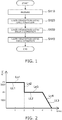
- FIG. 1 is a flowchart showing a laser processing method according to an embodiment.
- a processing object is prepared as shown in FIG. 1 (step S110).
- the processing object 10 (referring to FIG. 3A ) is, for example, a structure body including a metal material.
- the processing object 10 includes, for example, a metal.
- the metal includes, for example, at least one selected from the group consisting of aluminum (Al) and iron (Fe).
- the processing object 10 may include, for example, an alloy including the metal recited above.
- the processing object 10 includes, for example, an aluminum alloy.
- the aluminum alloy includes at least one selected from the group consisting of aluminum, manganese (Mn), and magnesium (Mg).
- step S120 an irradiation based on a first condition is performed (step S120).
- a first laser light is irradiated on a first region 10r of the processing object 10 (referring to FIG. 3A ).
- the first region 10r includes, for example, at least a portion of a surface 10s of the processing object 10 (referring to FIG. 3A ).
- the first laser light is irradiated on the first region 10r; and a portion of the processing object 10 (a portion including the first region 10r) is heated.
- a pulsed laser or the like is used as the laser emitting the first laser light.
- the output value of the first laser light is 3000 W or more.
- the output value of the first laser light may be, for example, not less than 3000 W and not more than 3300 W.
- the irradiation time of the first laser light is not less than 1.0 ms and not more than 2.0 ms.
- step S130 an irradiation based on a second condition is performed (step S130).
- a second laser light is irradiated on the first region 10r of the processing object 10 recited above.
- the second laser light is irradiated on the first region 10r of the processing object 10; and a portion of the processing object 10 (a portion including the first region 10r) is heated.
- the pulsed laser or the like of step S120 may be used as the laser emitting the second laser light.
- Such a second laser light is irradiated on the first region 10r of the processing object 10 (the region where the first laser light is irradiated in step S120).
- the output value of the second laser light is not less than 60% and not more than 70% of the output value of the first laser light of the first condition.
- the output value of the second laser light is, for example, not less than 1800 W and not more than 2310 W.
- the irradiation time of the second laser light is not less than 2.0 ms and not more than 3.0 ms.
- step S140 an irradiation based on a third condition is performed (step S140).
- the third laser light is further irradiated on the first region 10r of the processing object 10 recited above.
- the third laser light is irradiated on the first region 10r of the processing object 10; and a portion of the processing object 10 (a portion including the first region 10r) is heated.
- the pulsed laser or the like of steps S120 and S130 may be used as the laser emitting the third laser light.
- the output value of the third laser light of the third condition is lower than the output value of the second laser light of the second condition.
- the output value of the third laser light may decrease as time elapses.
- the temporal change of the output value of the third laser light may be set to decrease linearly as time elapses.
- the irradiation time of the third laser light is not less than 0.5 ms and not more than 1.5 ms.
- the irradiation time of the third laser light may be about 1.0 ms.
- the laser light of the multiple conditions recited above is irradiated on the processing object 10; and a weld portion 20 inside the processing object 10 (referring to FIG. 3B , etc.) is heated.
- the weld portion 20 includes at least a portion of the first region 10r (referring to FIG. 3A ).
- the metal at the weld portion 20 is melted by the heat due to the laser light.
- the welding is performed by the melted metal solidifying after the melting.
- the laser processing method according to the embodiment is applicable to a method for manufacturing a secondary cell, etc.
- a case inside the secondary cell can be joined using the laser processing method according to the embodiment.
- the terminals of multiple secondary cells can be electrically connected to each other using the laser processing method according to the embodiment.
- Examples of irradiation conditions of the laser for the laser processing will now be described.
- An example of the irradiation conditions of the laser light in the case where the laser light is emitted from a pulsed laser and irradiated on the processing object 10 will now be described.
- FIG. 2 is a figure showing the output of the laser.
- FIG. 2 shows an example of the relationship between the output value of the laser light and the irradiation time.
- the horizontal axis of FIG. 2 corresponds to a time t (ms).
- the vertical axis of FIG. 2 shows an output value P (W) of the laser light.
- a first laser light LL1 based on the first condition is irradiated on the surface 10s (the first region 10r) of the processing object 10.
- the output value P is a first output value P1; and the irradiation time is 2.0 ms.
- the first output value P1 is 3100 W.
- the first laser light LL1 of the first output value P1 is irradiated on the surface 10s (the first region 10r) of the processing object 10 for a time of 2.0 ms.
- the line Ln1 shown in FIG. 2 corresponds to the irradiation condition of the laser light of step S120 of FIG. 1 .
- the output value P of the laser light is set to be lower.
- a second laser light LL2 based on the second condition is irradiated on the surface 10s (the first region 10r) of the processing object 10.
- the output value P is a second output value P2; and the irradiation time is 2.0.
- the second output value P2 is 2000 W.
- the second laser light LL2 of the second output value P2 is irradiated on the surface 10s (the first region 10r) of the processing object 10 for a time of 2.0 ms.
- the line Ln3 of FIG. 2 corresponds to the irradiation condition of the laser light of step S130 of FIG. 1 .
- a third laser light LL3 based on the third condition is irradiated on the surface 10s (the first region 10r) of the processing object 10.
- the output value P is lower than the second output value P2; and the irradiation time is 1.0 ms.
- the output value P of the third laser light LL3 gradually decreases. For example, at least a portion of the gradual decrease is linear as the time t elapses.
- the line Ln4 of FIG. 2 corresponds to the irradiation condition of the laser of step S140 of FIG. 1 .
- the output value P of the pulsed laser may include, for example, the conditions illustrated by the lines Ln1 to Ln4 of FIG. 2 . Pulsed lasers that have such conditions are irradiated on the processing object 10.
- FIG. 3A, FIG. 3B , FIG. 4A, FIG. 4B , FIG. 5A, FIG. 5B , FIG. 6A, and FIG. 6B are drawings showing states of the processing object 10.
- FIGS. 1-10 show, in stages, the states of the weld portion 20 of the processing object 10 in the laser processing method according to the embodiment. Examples of the states of the processing object 10 are described hereinbelow for the case where the pulsed laser is irradiated on the processing object 10 from above in the drawing.
- the processing object 10 is prepared as shown in FIG. 3A .
- the processing object 10 is, for example, a structure body including a metal material.
- the state of the processing object 10 shown in FIG. 3A is the state of the processing object 10 before the laser light is irradiated. This state corresponds to the state of the processing object 10 of step S110 of FIG. 1 .
- the processing object 10 includes the first region 10r.
- the first region 10r includes the surface 10s of the processing object 10.
- the first laser light LL1 of the first condition is irradiated on the first region 10r of the processing object 10.
- the first laser light LL1 that is 3000 W or more is irradiated on the surface 10s of the processing object 10.
- the surface 10s of the processing object 10 is heated by the laser; thereby, the processing object 10 melts; and a liquid portion 10a is formed.
- the liquid portion 10a is a liquid metal.
- the weld portion 20 that includes a hole 20a is formed.
- the weld portion 20 includes the liquid portion 10a and the hole 20a.
- the irradiation based on the first condition is performed further.
- the processing object 10 is melted further; and the volume of the liquid portion 10a becomes large.
- the temperature of the upper portion of the weld portion 20 becomes high.
- the volume of the liquid portion 10a becomes large easily at the upper portion.
- a void 20b forms at the lower portion of the weld portion 20 due to differences of how the volume of the liquid portion 10a increases within the weld portion 20.
- the states of the processing object 10 shown in FIG. 3B and FIG. 4A correspond to the state of the processing object 10 of step S120 of FIG. 1 .
- one void 20b is formed at the lower portion of the weld portion 20.
- multiple voids 20b are formed.
- the irradiation based on the second condition is performed.
- the output value P of the laser light of the second condition is not less than 60% and not more than 70% of the output value P of the first condition.
- the volume of the hole 20a increases; and the volume of the void 20b decreases.
- the liquid portion 10a at the periphery of the void 20b vibrates.
- the volume of the void 20b decreases.
- the irradiation based on the second condition is performed further.
- the void 20b is removed; and the hole 20a remains in the weld portion 20.
- the liquid portion 10a at the periphery of the void 20b vibrates; and the void 20b is removed.
- the void 20b that is formed by the irradiation using the first condition (referring to FIG. 4A ) is removed.
- the states of the processing object 10 shown in FIG. 4B and FIG. 5A correspond to the state of the processing object 10 of step S130 of FIG. 1 .
- the void 20b is removed after the volume of the void 20b decreases.
- the void 20b remains after the volume of the void 20b decreases.
- the irradiation based on the third condition is performed.
- the output value P of the laser light of the third condition is lower than the output value P of the second condition.
- the volume of the liquid portion 10a increases; and the remaining space of the hole 20a becomes small.
- the irradiation based on the third condition is continued.
- the liquid portion 10a is formed in the hole 20a to fill the hole 20a.
- the states of the processing object 10 shown in FIG. 5B and FIG. 6A correspond to the state of the processing object 10 of step S140 of FIG. 1 .
- the liquid portion 10a changes into a solid portion 10b by, for example, the liquid metal solidifying at the weld portion 20.
- the welding processing is performed by the solidification of the melted metal.
- FIG. 7 is a drawing showing the configuration example of the laser processing apparatus.
- FIG. 8A and FIG. 8B are drawings showing portions of the laser processing apparatus.
- the laser processing apparatus 50 for performing the laser processing method according to the embodiment is shown in FIG. 7 ; and configuration examples of a laser processing head 4 are shown in FIG. 8A and FIG. 8B .
- a laser oscillator 1, an optical fiber 2, a controller 3, and the laser processing head 4 are provided in the laser processing apparatus 50.
- the laser oscillator 1 is, for example, a laser based on a crystal such as YAG, etc.
- the laser includes, for example, at least one of a fiber laser or a disk laser.
- the light of the pulsed laser propagates through the optical fiber 2.
- the controller 3 is connected to the laser oscillator 1 and makes pulse oscillation possible.
- the controller 3 sets the temporal change of the output value P of the pulsed laser.
- the controller 3 sets the oscillation frequency and the emission energy of the pulsed laser emitted from the laser oscillator 1.
- Laser light L is emitted from the laser processing head 4.
- lenses 5a1 and 5a2 and a mirror 5b are provided in a laser processing head 4A.
- Laser light L1 from the optical fiber 2 is supplied to the laser processing head 4A.
- the laser light L1 is condensed by the lens 5a1, subsequently reflected by the mirror 5b, and again condensed by the lens 5a2.
- lenses 6a1 and 6a2 are provided in a laser processing head 4B.
- the lens 6a1 is, for example, a collimating lens.
- Laser light L2 from the optical fiber 2 is adjusted to be substantially parallel light by the lens 6a1.
- the laser light L2 from the optical fiber 2 is supplied to the laser processing head 4B. Inside the laser processing head 4B, the laser light L2 is caused to be substantially parallel light by the lens 6a1, and subsequently is condensed by the lens 6a2.
- the configuration of one of the laser processing head 4A or 4B is applicable to the laser processing head 4 of FIG. 7 .
- the laser light L that is output from the laser oscillator 1 enters the optical fiber 2.
- the laser light L from the optical fiber 2 is supplied to the laser processing head 4. Subsequently, the laser light L from the laser processing head 4 is irradiated on the surface 10s of the processing object 10.
- a laser having the output value P of 3000 W or more is irradiated on the processing object 10; subsequently, as the second condition, a laser having the output value P of not less than 60% and not more than 70% of the output value P of the first condition is irradiated on the processing object 10.
- the occurrence of the void 20b at the weld portion 20 can be suppressed by irradiating the laser on the processing object 10 in stages.
- FIG. 9 is a figure showing the relationship between the laser output and the void occurrence rate.
- the vertical axis is a diameter d1 of the void 20b.
- the output value P of the first irradiation is 3100 W.
- the diameter d1 of the void 20b corresponds to the diameter of a sphere in the case where the configuration of the void 20b is spherical.
- the round symbols illustrate the diameter d1 of the void 20b when the ratio R1 is 20% to 100%.
- the square symbol of FIG. 9 shows the diameter d1 of the void 20b in the case where the ratio R1 is 0% and the second laser irradiation is not performed.
- the diameter d1 of the void 20b is smaller when the ratio R1 is not less than 60% and not more than 70%.
- the straight lines extending above and below the round symbols show the ranges of the diameter d1 of the void 20b.
- the value of the diameter d1 of the void 20b is in the range of 0.1 mm to 0.45 mm.
- FIG. 10 is a figure showing the relationship between the laser output and the void occurrence rate.
- the horizontal axis is the ratio R1 of the output value P of the laser of the second irradiation to the output value P of the laser of the first irradiation.
- the vertical axis of FIG. 10 is a number Nb1 of the voids 20b.
- the output value P of the first irradiation is 3100 W.
- the round symbols show the number Nb1 of the voids 20b when the ratio R1 is 20% to 100%.
- the square symbol shows the number Nb1 of the voids 20b in the case where the ratio R1 is 0% and the second irradiation is not performed. It can be seen from FIG. 10 that compared to the other ranges of the ratio R1, the number Nb1 of the voids 20b is smaller when the ratio R1 is not less than 60% and not more than 70%.
- FIG. 11 is a drawing showing the state of a weld portion of a reference example.
- the welding processing is performed by irradiating the laser on the surface of a processing object 100, by the processing object 100 melting, and by the melted metal solidifying and changing into a solid portion 100b.
- a void 200b occurs easily at the lower portion of a weld portion 200.
- the quality of the welding processing decreases due to the occurrence of the void 200b.
- the reliability of the apparatus may decrease due to the occurrence of the void 200b.
- a laser having the output value P of 3000 W or more is irradiated on the processing object 10 as the first condition; subsequently, a laser having the output value P of not less than 60% and not more than 70% of the output value P of the first condition is irradiated on the processing object 10 as the second condition.
- the volume of the void 20b is reduced by irradiating the laser on the weld portion 20 using the condition of the output value P of the laser light being not less than 60% and not more than 70% of the output value P of the first condition.
- the void 20b is removed after the volume decreases. The occurrence of the void 20b at the weld portion 20 is suppressed.
- a laser processing method having higher reliability is provided.
Landscapes
- Physics & Mathematics (AREA)
- Optics & Photonics (AREA)
- Engineering & Computer Science (AREA)
- Plasma & Fusion (AREA)
- Mechanical Engineering (AREA)
- Laser Beam Processing (AREA)
Abstract
Description
- Embodiments described herein relate generally to a laser processing method.
- A joining method that uses laser welding is used as a processing method having good production efficiency. For example, components that are included in an apparatus are welded to each other using laser light such as a pulsed laser, etc. In laser welding, there are cases where cracks and/or bubbles occur in the welded portion, and the reliability of the apparatus decreases.
-
-
FIG. 1 is a flowchart showing a laser processing method according to an embodiment; -
FIG. 2 is a figure showing the output of the laser; -
FIG. 3A and FIG. 3B are drawings showing states of a weld portion; -
FIG. 4A and FIG. 4B are drawings showing states of the weld portion; -
FIG. 5A and FIG. 5B are drawings showing states of the weld portion; -
FIG. 6A and FIG. 6B are drawings showing states of the weld portion; -
FIG. 7 is a drawing showing the configuration example of a laser processing apparatus; -
FIG. 8A and FIG. 8B are drawings showing portions of the laser processing apparatus; -
FIG. 9 is a figure showing the relationship between the laser output and the void occurrence rate; -
FIG. 10 is a figure showing the relationship between the laser output and the void occurrence rate; and -
FIG. 11 is a drawing showing the state of a weld portion of a reference example. - According to an embodiment of the invention, a laser processing method includes a first irradiation process and a second irradiation process. In the first irradiation process, a first laser light is irradiated on a first region of a processing object including a metal. A first output value of the first laser light is 3000 W or more. In the second irradiation process, a second laser light is irradiated on the first region. A second output value of the second laser light is not less than 60% and not more than 70% of the first output value.
- Various embodiments are described below with reference to the accompanying drawings.
- The drawings are schematic and conceptual; and the relationships between the thickness and width of portions, the proportions of sizes among portions, etc., are not necessarily the same as the actual values. The dimensions and proportions may be illustrated differently among drawings, even for identical portions.
- In the specification and drawings, components similar to those described previously or illustrated in an antecedent drawing are marked with like reference numerals, and a detailed description is omitted as appropriate.
-
FIG. 1 is a flowchart showing a laser processing method according to an embodiment. - A processing object is prepared as shown in
FIG. 1 (step S110). The processing object 10 (referring toFIG. 3A ) is, for example, a structure body including a metal material. Theprocessing object 10 includes, for example, a metal. The metal includes, for example, at least one selected from the group consisting of aluminum (Al) and iron (Fe). Theprocessing object 10 may include, for example, an alloy including the metal recited above. Theprocessing object 10 includes, for example, an aluminum alloy. The aluminum alloy includes at least one selected from the group consisting of aluminum, manganese (Mn), and magnesium (Mg). - After step S110, an irradiation based on a first condition is performed (step S120). In step S120, a first laser light is irradiated on a
first region 10r of the processing object 10 (referring toFIG. 3A ). Thefirst region 10r includes, for example, at least a portion of asurface 10s of the processing object 10 (referring toFIG. 3A ). The first laser light is irradiated on thefirst region 10r; and a portion of the processing object 10 (a portion including thefirst region 10r) is heated. A pulsed laser or the like is used as the laser emitting the first laser light. In the first condition, the output value of the first laser light is 3000 W or more. In the first condition, the output value of the first laser light may be, for example, not less than 3000 W and not more than 3300 W. In the first condition of one example, the irradiation time of the first laser light is not less than 1.0 ms and not more than 2.0 ms. - After step S120, an irradiation based on a second condition is performed (step S130). In step S130, a second laser light is irradiated on the
first region 10r of theprocessing object 10 recited above. The second laser light is irradiated on thefirst region 10r of theprocessing object 10; and a portion of the processing object 10 (a portion including thefirst region 10r) is heated. For example, the pulsed laser or the like of step S120 may be used as the laser emitting the second laser light. Such a second laser light is irradiated on thefirst region 10r of the processing object 10 (the region where the first laser light is irradiated in step S120). In the second condition, the output value of the second laser light is not less than 60% and not more than 70% of the output value of the first laser light of the first condition. In the second condition, the output value of the second laser light is, for example, not less than 1800 W and not more than 2310 W. In the second condition of one example, the irradiation time of the second laser light is not less than 2.0 ms and not more than 3.0 ms. - After step S130, an irradiation based on a third condition is performed (step S140). In step S140, the third laser light is further irradiated on the
first region 10r of theprocessing object 10 recited above. The third laser light is irradiated on thefirst region 10r of theprocessing object 10; and a portion of the processing object 10 (a portion including thefirst region 10r) is heated. For example, the pulsed laser or the like of steps S120 and S130 may be used as the laser emitting the third laser light. The output value of the third laser light of the third condition is lower than the output value of the second laser light of the second condition. For example, in the third condition, the output value of the third laser light may decrease as time elapses. For example, at least a portion of the temporal change of the output value of the third laser light may be set to decrease linearly as time elapses. In the third condition of one example, the irradiation time of the third laser light is not less than 0.5 ms and not more than 1.5 ms. For example, in the third condition, the irradiation time of the third laser light may be about 1.0 ms. - By steps S120 to S140, the laser light of the multiple conditions recited above is irradiated on the
processing object 10; and aweld portion 20 inside the processing object 10 (referring toFIG. 3B , etc.) is heated. Theweld portion 20 includes at least a portion of thefirst region 10r (referring toFIG. 3A ). The metal at theweld portion 20 is melted by the heat due to the laser light. The welding is performed by the melted metal solidifying after the melting. For example, the laser processing method according to the embodiment is applicable to a method for manufacturing a secondary cell, etc. For example, a case inside the secondary cell can be joined using the laser processing method according to the embodiment. The terminals of multiple secondary cells can be electrically connected to each other using the laser processing method according to the embodiment. - Examples of irradiation conditions of the laser for the laser processing will now be described. An example of the irradiation conditions of the laser light in the case where the laser light is emitted from a pulsed laser and irradiated on the
processing object 10 will now be described. -
FIG. 2 is a figure showing the output of the laser. -
FIG. 2 shows an example of the relationship between the output value of the laser light and the irradiation time. The horizontal axis ofFIG. 2 corresponds to a time t (ms). The vertical axis ofFIG. 2 shows an output value P (W) of the laser light. - As shown by a line Ln1 of
FIG. 2 , a first laser light LL1 based on the first condition is irradiated on thesurface 10s (thefirst region 10r) of theprocessing object 10. For example, for the first laser light LL1, the output value P is a first output value P1; and the irradiation time is 2.0 ms. In the example, the first output value P1 is 3100 W. For example, the first laser light LL1 of the first output value P1 is irradiated on thesurface 10s (thefirst region 10r) of theprocessing object 10 for a time of 2.0 ms. The line Ln1 shown inFIG. 2 corresponds to the irradiation condition of the laser light of step S120 ofFIG. 1 . - Then, as shown by a line Ln2 of
FIG. 2 , the output value P of the laser light is set to be lower. - Then, as shown by a line Ln3 of
FIG. 2 , a second laser light LL2 based on the second condition is irradiated on thesurface 10s (thefirst region 10r) of theprocessing object 10. For example, for the second laser light LL2, the output value P is a second output value P2; and the irradiation time is 2.0. In the example, the second output value P2 is 2000 W. For example, the second laser light LL2 of the second output value P2 is irradiated on thesurface 10s (thefirst region 10r) of theprocessing object 10 for a time of 2.0 ms. The line Ln3 ofFIG. 2 corresponds to the irradiation condition of the laser light of step S130 ofFIG. 1 . - Then, as shown by a line Ln4 of
FIG. 2 , a third laser light LL3 based on the third condition is irradiated on thesurface 10s (thefirst region 10r) of theprocessing object 10. For example, for the third laser light LL3, the output value P is lower than the second output value P2; and the irradiation time is 1.0 ms. The output value P of the third laser light LL3 gradually decreases. For example, at least a portion of the gradual decrease is linear as the time t elapses. The line Ln4 ofFIG. 2 corresponds to the irradiation condition of the laser of step S140 ofFIG. 1 . - In the embodiment, the output value P of the pulsed laser may include, for example, the conditions illustrated by the lines Ln1 to Ln4 of
FIG. 2 . Pulsed lasers that have such conditions are irradiated on theprocessing object 10. - Examples of states of the
processing object 10 due to the laser processing will now be described. -
FIG. 3A, FIG. 3B ,FIG. 4A, FIG. 4B ,FIG. 5A, FIG. 5B ,FIG. 6A, and FIG. 6B are drawings showing states of theprocessing object 10. - These drawings show, in stages, the states of the
weld portion 20 of theprocessing object 10 in the laser processing method according to the embodiment. Examples of the states of theprocessing object 10 are described hereinbelow for the case where the pulsed laser is irradiated on theprocessing object 10 from above in the drawing. - The
processing object 10 is prepared as shown inFIG. 3A . Theprocessing object 10 is, for example, a structure body including a metal material. - The state of the
processing object 10 shown inFIG. 3A is the state of theprocessing object 10 before the laser light is irradiated. This state corresponds to the state of theprocessing object 10 of step S110 ofFIG. 1 . As shown inFIG. 3A , theprocessing object 10 includes thefirst region 10r. Thefirst region 10r includes thesurface 10s of theprocessing object 10. - As shown in
FIG. 3B , the first laser light LL1 of the first condition is irradiated on thefirst region 10r of theprocessing object 10. The first laser light LL1 that is 3000 W or more is irradiated on thesurface 10s of theprocessing object 10. Thesurface 10s of theprocessing object 10 is heated by the laser; thereby, theprocessing object 10 melts; and aliquid portion 10a is formed. In the case where theprocessing object 10 is formed of a metal material, theliquid portion 10a is a liquid metal. By melting theprocessing object 10, theweld portion 20 that includes ahole 20a is formed. Theweld portion 20 includes theliquid portion 10a and thehole 20a. - As shown in
FIG. 4A , the irradiation based on the first condition is performed further. By the irradiation using the first condition, theprocessing object 10 is melted further; and the volume of theliquid portion 10a becomes large. By the irradiation of the laser, the temperature of the upper portion of theweld portion 20 becomes high. Compared to the lower portion of theweld portion 20, the volume of theliquid portion 10a becomes large easily at the upper portion. A void 20b forms at the lower portion of theweld portion 20 due to differences of how the volume of theliquid portion 10a increases within theweld portion 20. - The states of the
processing object 10 shown inFIG. 3B andFIG. 4A correspond to the state of theprocessing object 10 of step S120 ofFIG. 1 . In the example shown inFIG. 4A , onevoid 20b is formed at the lower portion of theweld portion 20. There are also cases wheremultiple voids 20b are formed. - As shown in
FIG. 4B , the irradiation based on the second condition is performed. The output value P of the laser light of the second condition is not less than 60% and not more than 70% of the output value P of the first condition. Thereby, the volume of thehole 20a increases; and the volume of the void 20b decreases. For example, by irradiating the laser using the second condition via thehole 20a, theliquid portion 10a at the periphery of the void 20b vibrates. As a result, the volume of the void 20b decreases. - As shown in
FIG. 5A , the irradiation based on the second condition is performed further. By the irradiation using the second condition, for example, the void 20b is removed; and thehole 20a remains in theweld portion 20. For example, by continuing the irradiation using the second condition via thehole 20a, theliquid portion 10a at the periphery of the void 20b vibrates; and the void 20b is removed. Thus, the void 20b that is formed by the irradiation using the first condition (referring toFIG. 4A ) is removed. - The states of the
processing object 10 shown inFIG. 4B andFIG. 5A correspond to the state of theprocessing object 10 of step S130 ofFIG. 1 . In the example ofFIG. 4B andFIG. 5A , the void 20b is removed after the volume of the void 20b decreases. There are also cases where the void 20b remains after the volume of the void 20b decreases. - As shown in
FIG. 5B , the irradiation based on the third condition is performed. In the third condition, the output value P of the laser light of the third condition is lower than the output value P of the second condition. Thereby, the volume of theliquid portion 10a increases; and the remaining space of thehole 20a becomes small. - As shown in
FIG. 6A , the irradiation based on the third condition is continued. By the irradiation using the third condition, theliquid portion 10a is formed in thehole 20a to fill thehole 20a. - The states of the
processing object 10 shown inFIG. 5B andFIG. 6A correspond to the state of theprocessing object 10 of step S140 ofFIG. 1 . - Subsequently, after the irradiation of the laser as shown in
FIG. 6B , theliquid portion 10a changes into asolid portion 10b by, for example, the liquid metal solidifying at theweld portion 20. Thus, the welding processing is performed by the solidification of the melted metal. - A configuration example of a laser processing apparatus will now be described.
-
FIG. 7 is a drawing showing the configuration example of the laser processing apparatus. -
FIG. 8A and FIG. 8B are drawings showing portions of the laser processing apparatus. - The
laser processing apparatus 50 for performing the laser processing method according to the embodiment is shown inFIG. 7 ; and configuration examples of alaser processing head 4 are shown inFIG. 8A and FIG. 8B . - As shown in
FIG. 7 , alaser oscillator 1, anoptical fiber 2, acontroller 3, and thelaser processing head 4 are provided in thelaser processing apparatus 50. - The
laser oscillator 1 is, for example, a laser based on a crystal such as YAG, etc. The laser includes, for example, at least one of a fiber laser or a disk laser. The light of the pulsed laser propagates through theoptical fiber 2. Thecontroller 3 is connected to thelaser oscillator 1 and makes pulse oscillation possible. Thecontroller 3 sets the temporal change of the output value P of the pulsed laser. Thecontroller 3 sets the oscillation frequency and the emission energy of the pulsed laser emitted from thelaser oscillator 1. Laser light L is emitted from thelaser processing head 4. - As shown in
FIG. 8A , lenses 5a1 and 5a2 and amirror 5b are provided in alaser processing head 4A. Laser light L1 from theoptical fiber 2 is supplied to thelaser processing head 4A. Inside thelaser processing head 4A, the laser light L1 is condensed by the lens 5a1, subsequently reflected by themirror 5b, and again condensed by the lens 5a2. - As shown in
FIG. 8B , lenses 6a1 and 6a2 are provided in alaser processing head 4B. The lens 6a1 is, for example, a collimating lens. Laser light L2 from theoptical fiber 2 is adjusted to be substantially parallel light by the lens 6a1. The laser light L2 from theoptical fiber 2 is supplied to thelaser processing head 4B. Inside thelaser processing head 4B, the laser light L2 is caused to be substantially parallel light by the lens 6a1, and subsequently is condensed by the lens 6a2. - For example, the configuration of one of the
laser processing head laser processing head 4 ofFIG. 7 . - As illustrated in
FIG. 7 , the laser light L that is output from thelaser oscillator 1 enters theoptical fiber 2. The laser light L from theoptical fiber 2 is supplied to thelaser processing head 4. Subsequently, the laser light L from thelaser processing head 4 is irradiated on thesurface 10s of theprocessing object 10. - In the laser processing method according to the embodiment, as the first condition, a laser having the output value P of 3000 W or more is irradiated on the
processing object 10; subsequently, as the second condition, a laser having the output value P of not less than 60% and not more than 70% of the output value P of the first condition is irradiated on theprocessing object 10. By such irradiation conditions, the occurrence of the void 20b at theweld portion 20 can be suppressed by irradiating the laser on theprocessing object 10 in stages. - The investigation results that formed the basis of discovering the irradiation conditions of the laser such as those recited above will now be described.
-
FIG. 9 is a figure showing the relationship between the laser output and the void occurrence rate. - In
FIG. 9 , the horizontal axis is a ratio R1 of the output value P of the laser of the second irradiation to the output value P of the laser of the first irradiation (R1 = (P2/P1)×100%). The vertical axis is a diameter d1 of the void 20b. In the example ofFIG. 9 , the output value P of the first irradiation is 3100 W. For example, the diameter d1 of the void 20b corresponds to the diameter of a sphere in the case where the configuration of the void 20b is spherical. - In
FIG. 9 , the round symbols illustrate the diameter d1 of the void 20b when the ratio R1 is 20% to 100%. The square symbol ofFIG. 9 shows the diameter d1 of the void 20b in the case where the ratio R1 is 0% and the second laser irradiation is not performed. As shown inFIG. 9 , compared to the other ranges of the ratio R1, the diameter d1 of the void 20b is smaller when the ratio R1 is not less than 60% and not more than 70%. - In
FIG. 9 , the straight lines extending above and below the round symbols show the ranges of the diameter d1 of the void 20b. For example, in the case where the ratio R1 is 20%, the value of the diameter d1 of the void 20b is in the range of 0.1 mm to 0.45 mm. -
FIG. 10 is a figure showing the relationship between the laser output and the void occurrence rate. - In
FIG. 10 , the horizontal axis is the ratio R1 of the output value P of the laser of the second irradiation to the output value P of the laser of the first irradiation. The vertical axis ofFIG. 10 is a number Nb1 of thevoids 20b. In the example ofFIG. 10 , the output value P of the first irradiation is 3100 W. - As shown in
FIG. 10 , the round symbols show the number Nb1 of thevoids 20b when the ratio R1 is 20% to 100%. The square symbol shows the number Nb1 of thevoids 20b in the case where the ratio R1 is 0% and the second irradiation is not performed. It can be seen fromFIG. 10 that compared to the other ranges of the ratio R1, the number Nb1 of thevoids 20b is smaller when the ratio R1 is not less than 60% and not more than 70%. -
FIG. 11 is a drawing showing the state of a weld portion of a reference example. - Cracks and/or bubbles occur easily in the welded portion in laser welding using laser light such as a pulsed laser, etc. For example, as shown in
FIG. 11 , the welding processing is performed by irradiating the laser on the surface of aprocessing object 100, by theprocessing object 100 melting, and by the melted metal solidifying and changing into asolid portion 100b. In such a case, a void 200b occurs easily at the lower portion of aweld portion 200. There are cases where the quality of the welding processing decreases due to the occurrence of the void 200b. In the case where components used in an apparatus are welded to each other, the reliability of the apparatus may decrease due to the occurrence of the void 200b. - In the laser processing method according to the embodiment, a laser having the output value P of 3000 W or more is irradiated on the
processing object 10 as the first condition; subsequently, a laser having the output value P of not less than 60% and not more than 70% of the output value P of the first condition is irradiated on theprocessing object 10 as the second condition. By such irradiation conditions of the laser, the occurrence of the void 20b at theweld portion 20 can be suppressed by irradiating the laser light on theprocessing object 10 in stages. - For example, as shown in
FIG. 4B andFIG. 5A , the volume of the void 20b is reduced by irradiating the laser on theweld portion 20 using the condition of the output value P of the laser light being not less than 60% and not more than 70% of the output value P of the first condition. For example, the void 20b is removed after the volume decreases. The occurrence of the void 20b at theweld portion 20 is suppressed. - According to the embodiment, a laser processing method having higher reliability is provided.
- While certain embodiments have been described, these embodiments have been presented by way of example only, and are not intended to limit the scope of the inventions. Indeed, the novel embodiments described herein may be embodied in a variety of other forms; furthermore, various omissions, substitutions and changes in the form of the embodiments described herein may be made without departing from the spirit of the inventions. The accompanying claims and their equivalents are intended to cover such forms or modifications as would fall within the scope and spirit of the invention.
Claims (6)
- A laser processing method, comprising:a first irradiation process of irradiating a first laser light on a first region of a processing object, the processing object including a metal, a first output value of the first laser light being 3000 W or more; anda second irradiation process of irradiating a second laser light on the first region, a second output value of the second laser light being not less than 60% and not more than 70% of the first output value.
- The method according to claim 1, wherein
an irradiation time of the first laser light is not less than 1.0 ms and not more than 2.0 ms, and
an irradiation time of the second laser light is not less than 2.0 ms and not more than 3.0 ms. - The method according to claim 1 or 2, wherein the first output value is not less than 3000 W and not more than 3300 W.
- The method according to any one of claims 1 to 3, wherein
the processing object includes aluminum, and
the first laser light and the second laser light are pulse laser light. - The method according to any one of claims 1 to 4, further comprising a third irradiation process of irradiating a third laser light on the first region,
a third output value of the third laser light being lower than the second output value. - The method according to any one of claims 1 to 5, wherein at least a portion of the first region melts in the first irradiation process.
Applications Claiming Priority (1)
| Application Number | Priority Date | Filing Date | Title |
|---|---|---|---|
| JP2018045612A JP6845170B2 (en) | 2018-03-13 | 2018-03-13 | Laser processing method |
Publications (2)
| Publication Number | Publication Date |
|---|---|
| EP3539711A1 true EP3539711A1 (en) | 2019-09-18 |
| EP3539711B1 EP3539711B1 (en) | 2021-01-06 |
Family
ID=65717880
Family Applications (1)
| Application Number | Title | Priority Date | Filing Date |
|---|---|---|---|
| EP19161001.3A Active EP3539711B1 (en) | 2018-03-13 | 2019-03-06 | Laser processing method with pulsed first and second irradiations process with different output values |
Country Status (4)
| Country | Link |
|---|---|
| US (1) | US11458568B2 (en) |
| EP (1) | EP3539711B1 (en) |
| JP (1) | JP6845170B2 (en) |
| CN (1) | CN110270758A (en) |
Families Citing this family (4)
| Publication number | Priority date | Publication date | Assignee | Title |
|---|---|---|---|---|
| JP7515074B2 (en) * | 2020-06-19 | 2024-07-12 | パナソニックIpマネジメント株式会社 | Laser welding method and apparatus |
| WO2022054211A1 (en) * | 2020-09-10 | 2022-03-17 | Primetals Technologies Japan株式会社 | Laser processing method |
| CN116135398B (en) * | 2021-11-16 | 2025-07-04 | 通快(中国)有限公司 | Improvement method, welding method, processing system, control device, program product |
| JP7834858B2 (en) * | 2022-07-08 | 2026-03-24 | エルジー エナジー ソリューション リミテッド | Welding equipment, welding method, battery manufacturing equipment, and automobile manufacturing equipment |
Citations (4)
| Publication number | Priority date | Publication date | Assignee | Title |
|---|---|---|---|---|
| JPH10216973A (en) * | 1996-12-06 | 1998-08-18 | Nippon Light Metal Co Ltd | Laser welding method of aluminum and aluminum alloy |
| CN102091871A (en) * | 2011-01-10 | 2011-06-15 | 哈尔滨工业大学 | Laser pulse spot welding method for metal sheet |
| US20170001261A1 (en) * | 2014-01-10 | 2017-01-05 | Panasonic Intellectual Property Management Co., Ltd. | Laser welding method and laser welding device |
| WO2017022238A1 (en) * | 2015-08-05 | 2017-02-09 | パナソニックIpマネジメント株式会社 | Laser welding method |
Family Cites Families (14)
| Publication number | Priority date | Publication date | Assignee | Title |
|---|---|---|---|---|
| CA2093286A1 (en) * | 1992-04-03 | 1993-10-04 | Koichi Haruta | Pulse laser irradiation apparatus for coated metal material |
| JP3568387B2 (en) * | 1998-03-23 | 2004-09-22 | 三洋電機株式会社 | Manufacturing method of sealed battery |
| JP2003001452A (en) * | 2001-06-15 | 2003-01-08 | Furukawa Electric Co Ltd:The | Laser welding method and semiconductor laser module manufactured using the method |
| JP4191539B2 (en) * | 2003-06-05 | 2008-12-03 | パナソニック株式会社 | Output stabilization method of solid-state laser oscillator |
| CN101569961B (en) * | 2009-03-06 | 2011-08-03 | 深圳市大族激光科技股份有限公司 | Laser welding method for butting two pieces of metal sheets |
| JP5484147B2 (en) * | 2010-03-25 | 2014-05-07 | 株式会社神戸製鋼所 | Pulse laser welding method of aluminum alloy material |
| CN103071924B (en) * | 2013-02-05 | 2015-05-20 | 天津滨海雷克斯激光科技发展有限公司 | Method for laser welding thin metal workpieces with plating thickness smaller than 10Mu m |
| DE102014201715A1 (en) * | 2014-01-31 | 2015-08-06 | Trumpf Laser Gmbh | Method and device for spot welding of workpieces by means of laser pulses with green wavelength |
| CN105081573B (en) * | 2015-09-17 | 2017-10-03 | 中国电子科技集团公司第四十八研究所 | The laser seal welding technique of 3A21 aluminum alloy casings |
| CN105729036A (en) * | 2016-03-24 | 2016-07-06 | 远利(天津)海业机械工程有限公司 | Alloy material and technology for repairing turbocharger nozzle ring through pulse laser precision welding and addition |
| CN106001924A (en) * | 2016-05-30 | 2016-10-12 | 远利(天津)海业机械工程有限公司 | Laser additive remanufacturing and erosion-resistant surface strengthening technological method for erosive abraded precision workpiece in drilling tool of directional well |
| US10486272B2 (en) * | 2018-03-06 | 2019-11-26 | General Electric Company | Turbine blade tip rail formation and repair using laser welding |
| CN108511857A (en) * | 2018-03-16 | 2018-09-07 | 航天恒星科技有限公司 | A kind of thin cover board aluminium alloy air-tightness Laser seal welding structure of large scale and method |
| CN111001933A (en) * | 2019-11-24 | 2020-04-14 | 扬州海科电子科技有限公司 | Silicon-aluminum alloy cavity laser sealing and welding method of eight-channel TR component |
-
2018
- 2018-03-13 JP JP2018045612A patent/JP6845170B2/en active Active
-
2019
- 2019-03-05 US US16/292,391 patent/US11458568B2/en active Active
- 2019-03-06 EP EP19161001.3A patent/EP3539711B1/en active Active
- 2019-03-07 CN CN201910172080.1A patent/CN110270758A/en active Pending
Patent Citations (4)
| Publication number | Priority date | Publication date | Assignee | Title |
|---|---|---|---|---|
| JPH10216973A (en) * | 1996-12-06 | 1998-08-18 | Nippon Light Metal Co Ltd | Laser welding method of aluminum and aluminum alloy |
| CN102091871A (en) * | 2011-01-10 | 2011-06-15 | 哈尔滨工业大学 | Laser pulse spot welding method for metal sheet |
| US20170001261A1 (en) * | 2014-01-10 | 2017-01-05 | Panasonic Intellectual Property Management Co., Ltd. | Laser welding method and laser welding device |
| WO2017022238A1 (en) * | 2015-08-05 | 2017-02-09 | パナソニックIpマネジメント株式会社 | Laser welding method |
Also Published As
| Publication number | Publication date |
|---|---|
| US20190283175A1 (en) | 2019-09-19 |
| US11458568B2 (en) | 2022-10-04 |
| JP6845170B2 (en) | 2021-03-17 |
| EP3539711B1 (en) | 2021-01-06 |
| CN110270758A (en) | 2019-09-24 |
| JP2019155421A (en) | 2019-09-19 |
Similar Documents
| Publication | Publication Date | Title |
|---|---|---|
| EP3539711B1 (en) | Laser processing method with pulsed first and second irradiations process with different output values | |
| Katayama | Fundamentals and details of laser welding | |
| TWI694882B (en) | Laser welding method and laser welding apparatus | |
| US8105712B2 (en) | Sealed secondary battery, and method for manufacturing the battery | |
| CN102049614B (en) | Fusion welding method and fusion welding apparatus | |
| US11123817B2 (en) | Method of welding laminated metal foils | |
| JP6512474B2 (en) | Laser processing apparatus and laser welding quality determination method for battery | |
| US20150183058A1 (en) | Welding device, welding method, and method for producing battery (as amended) | |
| JPWO2011016200A1 (en) | Sealed battery and manufacturing method thereof | |
| JP2019005768A (en) | Welding method for laminated metal foil | |
| CN106392327B (en) | Metal plate laser welding fixture | |
| EP1537939B1 (en) | Solid-state laser welding process with a laser beam diameter controller having an aperture | |
| CN117655525B (en) | Automatic welding method and device for power battery connecting sheet | |
| KR101826389B1 (en) | Secondary Battery | |
| JP2019129126A (en) | Method for manufacturing battery | |
| KR102301294B1 (en) | Process for Preparing Battery Cell Comprising Ablation Step of Burr Using Fiber Pulse Type Laser | |
| US11338388B2 (en) | Laser keyhole welding structure of aluminum material and laser keyhole welding method | |
| JP2018111120A (en) | Laser welding success / failure judgment method | |
| KR20130133646A (en) | System and method utilizing fiber lasers for titanium welding using an argon cover gas | |
| US20250128353A1 (en) | Welding device, welding method, battery manufacturing device and vehicle manufacturing device | |
| JPH11245066A (en) | Laser welding method and secondary battery manufacturing method | |
| US20240399498A1 (en) | Welding method and welding structure of metal member | |
| CN114985913A (en) | Light beam shaping device for laser spot welding of dissimilar metal and laser welding equipment | |
| CN118043164A (en) | Welding device, welding method, battery manufacturing device, and vehicle manufacturing device | |
| JP5311207B2 (en) | Metal foil connection method and capacitor |
Legal Events
| Date | Code | Title | Description |
|---|---|---|---|
| PUAI | Public reference made under article 153(3) epc to a published international application that has entered the european phase |
Free format text: ORIGINAL CODE: 0009012 |
|
| STAA | Information on the status of an ep patent application or granted ep patent |
Free format text: STATUS: REQUEST FOR EXAMINATION WAS MADE |
|
| 17P | Request for examination filed |
Effective date: 20190306 |
|
| AK | Designated contracting states |
Kind code of ref document: A1 Designated state(s): AL AT BE BG CH CY CZ DE DK EE ES FI FR GB GR HR HU IE IS IT LI LT LU LV MC MK MT NL NO PL PT RO RS SE SI SK SM TR |
|
| AX | Request for extension of the european patent |
Extension state: BA ME |
|
| GRAP | Despatch of communication of intention to grant a patent |
Free format text: ORIGINAL CODE: EPIDOSNIGR1 |
|
| STAA | Information on the status of an ep patent application or granted ep patent |
Free format text: STATUS: GRANT OF PATENT IS INTENDED |
|
| RIC1 | Information provided on ipc code assigned before grant |
Ipc: B23K 26/26 20140101ALI20200724BHEP Ipc: B23K 26/22 20060101ALI20200724BHEP Ipc: B23K 26/06 20140101AFI20200724BHEP Ipc: B23K 26/0622 20140101ALI20200724BHEP |
|
| INTG | Intention to grant announced |
Effective date: 20200824 |
|
| GRAS | Grant fee paid |
Free format text: ORIGINAL CODE: EPIDOSNIGR3 |
|
| GRAA | (expected) grant |
Free format text: ORIGINAL CODE: 0009210 |
|
| STAA | Information on the status of an ep patent application or granted ep patent |
Free format text: STATUS: THE PATENT HAS BEEN GRANTED |
|
| AK | Designated contracting states |
Kind code of ref document: B1 Designated state(s): AL AT BE BG CH CY CZ DE DK EE ES FI FR GB GR HR HU IE IS IT LI LT LU LV MC MK MT NL NO PL PT RO RS SE SI SK SM TR |
|
| REG | Reference to a national code |
Ref country code: GB Ref legal event code: FG4D |
|
| REG | Reference to a national code |
Ref country code: AT Ref legal event code: REF Ref document number: 1351838 Country of ref document: AT Kind code of ref document: T Effective date: 20210115 Ref country code: CH Ref legal event code: EP |
|
| REG | Reference to a national code |
Ref country code: DE Ref legal event code: R096 Ref document number: 602019002024 Country of ref document: DE |
|
| REG | Reference to a national code |
Ref country code: IE Ref legal event code: FG4D |
|
| REG | Reference to a national code |
Ref country code: NL Ref legal event code: MP Effective date: 20210106 |
|
| REG | Reference to a national code |
Ref country code: AT Ref legal event code: MK05 Ref document number: 1351838 Country of ref document: AT Kind code of ref document: T Effective date: 20210106 |
|
| REG | Reference to a national code |
Ref country code: LT Ref legal event code: MG9D |
|
| PG25 | Lapsed in a contracting state [announced via postgrant information from national office to epo] |
Ref country code: BG Free format text: LAPSE BECAUSE OF FAILURE TO SUBMIT A TRANSLATION OF THE DESCRIPTION OR TO PAY THE FEE WITHIN THE PRESCRIBED TIME-LIMIT Effective date: 20210406 Ref country code: FI Free format text: LAPSE BECAUSE OF FAILURE TO SUBMIT A TRANSLATION OF THE DESCRIPTION OR TO PAY THE FEE WITHIN THE PRESCRIBED TIME-LIMIT Effective date: 20210106 Ref country code: HR Free format text: LAPSE BECAUSE OF FAILURE TO SUBMIT A TRANSLATION OF THE DESCRIPTION OR TO PAY THE FEE WITHIN THE PRESCRIBED TIME-LIMIT Effective date: 20210106 Ref country code: GR Free format text: LAPSE BECAUSE OF FAILURE TO SUBMIT A TRANSLATION OF THE DESCRIPTION OR TO PAY THE FEE WITHIN THE PRESCRIBED TIME-LIMIT Effective date: 20210407 Ref country code: PT Free format text: LAPSE BECAUSE OF FAILURE TO SUBMIT A TRANSLATION OF THE DESCRIPTION OR TO PAY THE FEE WITHIN THE PRESCRIBED TIME-LIMIT Effective date: 20210506 Ref country code: NO Free format text: LAPSE BECAUSE OF FAILURE TO SUBMIT A TRANSLATION OF THE DESCRIPTION OR TO PAY THE FEE WITHIN THE PRESCRIBED TIME-LIMIT Effective date: 20210406 Ref country code: LT Free format text: LAPSE BECAUSE OF FAILURE TO SUBMIT A TRANSLATION OF THE DESCRIPTION OR TO PAY THE FEE WITHIN THE PRESCRIBED TIME-LIMIT Effective date: 20210106 |
|
| PG25 | Lapsed in a contracting state [announced via postgrant information from national office to epo] |
Ref country code: AT Free format text: LAPSE BECAUSE OF FAILURE TO SUBMIT A TRANSLATION OF THE DESCRIPTION OR TO PAY THE FEE WITHIN THE PRESCRIBED TIME-LIMIT Effective date: 20210106 Ref country code: PL Free format text: LAPSE BECAUSE OF FAILURE TO SUBMIT A TRANSLATION OF THE DESCRIPTION OR TO PAY THE FEE WITHIN THE PRESCRIBED TIME-LIMIT Effective date: 20210106 Ref country code: RS Free format text: LAPSE BECAUSE OF FAILURE TO SUBMIT A TRANSLATION OF THE DESCRIPTION OR TO PAY THE FEE WITHIN THE PRESCRIBED TIME-LIMIT Effective date: 20210106 Ref country code: LV Free format text: LAPSE BECAUSE OF FAILURE TO SUBMIT A TRANSLATION OF THE DESCRIPTION OR TO PAY THE FEE WITHIN THE PRESCRIBED TIME-LIMIT Effective date: 20210106 Ref country code: SE Free format text: LAPSE BECAUSE OF FAILURE TO SUBMIT A TRANSLATION OF THE DESCRIPTION OR TO PAY THE FEE WITHIN THE PRESCRIBED TIME-LIMIT Effective date: 20210106 |
|
| PG25 | Lapsed in a contracting state [announced via postgrant information from national office to epo] |
Ref country code: IS Free format text: LAPSE BECAUSE OF FAILURE TO SUBMIT A TRANSLATION OF THE DESCRIPTION OR TO PAY THE FEE WITHIN THE PRESCRIBED TIME-LIMIT Effective date: 20210506 |
|
| REG | Reference to a national code |
Ref country code: DE Ref legal event code: R097 Ref document number: 602019002024 Country of ref document: DE |
|
| PG25 | Lapsed in a contracting state [announced via postgrant information from national office to epo] |
Ref country code: MC Free format text: LAPSE BECAUSE OF FAILURE TO SUBMIT A TRANSLATION OF THE DESCRIPTION OR TO PAY THE FEE WITHIN THE PRESCRIBED TIME-LIMIT Effective date: 20210106 Ref country code: CZ Free format text: LAPSE BECAUSE OF FAILURE TO SUBMIT A TRANSLATION OF THE DESCRIPTION OR TO PAY THE FEE WITHIN THE PRESCRIBED TIME-LIMIT Effective date: 20210106 Ref country code: EE Free format text: LAPSE BECAUSE OF FAILURE TO SUBMIT A TRANSLATION OF THE DESCRIPTION OR TO PAY THE FEE WITHIN THE PRESCRIBED TIME-LIMIT Effective date: 20210106 Ref country code: SM Free format text: LAPSE BECAUSE OF FAILURE TO SUBMIT A TRANSLATION OF THE DESCRIPTION OR TO PAY THE FEE WITHIN THE PRESCRIBED TIME-LIMIT Effective date: 20210106 |
|
| PLBE | No opposition filed within time limit |
Free format text: ORIGINAL CODE: 0009261 |
|
| STAA | Information on the status of an ep patent application or granted ep patent |
Free format text: STATUS: NO OPPOSITION FILED WITHIN TIME LIMIT |
|
| PG25 | Lapsed in a contracting state [announced via postgrant information from national office to epo] |
Ref country code: SK Free format text: LAPSE BECAUSE OF FAILURE TO SUBMIT A TRANSLATION OF THE DESCRIPTION OR TO PAY THE FEE WITHIN THE PRESCRIBED TIME-LIMIT Effective date: 20210106 Ref country code: RO Free format text: LAPSE BECAUSE OF FAILURE TO SUBMIT A TRANSLATION OF THE DESCRIPTION OR TO PAY THE FEE WITHIN THE PRESCRIBED TIME-LIMIT Effective date: 20210106 Ref country code: DK Free format text: LAPSE BECAUSE OF FAILURE TO SUBMIT A TRANSLATION OF THE DESCRIPTION OR TO PAY THE FEE WITHIN THE PRESCRIBED TIME-LIMIT Effective date: 20210106 |
|
| 26N | No opposition filed |
Effective date: 20211007 |
|
| REG | Reference to a national code |
Ref country code: BE Ref legal event code: MM Effective date: 20210331 |
|
| PG25 | Lapsed in a contracting state [announced via postgrant information from national office to epo] |
Ref country code: AL Free format text: LAPSE BECAUSE OF FAILURE TO SUBMIT A TRANSLATION OF THE DESCRIPTION OR TO PAY THE FEE WITHIN THE PRESCRIBED TIME-LIMIT Effective date: 20210106 Ref country code: LU Free format text: LAPSE BECAUSE OF NON-PAYMENT OF DUE FEES Effective date: 20210306 Ref country code: IE Free format text: LAPSE BECAUSE OF NON-PAYMENT OF DUE FEES Effective date: 20210306 Ref country code: ES Free format text: LAPSE BECAUSE OF FAILURE TO SUBMIT A TRANSLATION OF THE DESCRIPTION OR TO PAY THE FEE WITHIN THE PRESCRIBED TIME-LIMIT Effective date: 20210106 |
|
| PG25 | Lapsed in a contracting state [announced via postgrant information from national office to epo] |
Ref country code: SI Free format text: LAPSE BECAUSE OF FAILURE TO SUBMIT A TRANSLATION OF THE DESCRIPTION OR TO PAY THE FEE WITHIN THE PRESCRIBED TIME-LIMIT Effective date: 20210106 |
|
| PG25 | Lapsed in a contracting state [announced via postgrant information from national office to epo] |
Ref country code: IT Free format text: LAPSE BECAUSE OF FAILURE TO SUBMIT A TRANSLATION OF THE DESCRIPTION OR TO PAY THE FEE WITHIN THE PRESCRIBED TIME-LIMIT Effective date: 20210106 |
|
| PG25 | Lapsed in a contracting state [announced via postgrant information from national office to epo] |
Ref country code: IS Free format text: LAPSE BECAUSE OF FAILURE TO SUBMIT A TRANSLATION OF THE DESCRIPTION OR TO PAY THE FEE WITHIN THE PRESCRIBED TIME-LIMIT Effective date: 20210506 |
|
| PG25 | Lapsed in a contracting state [announced via postgrant information from national office to epo] |
Ref country code: BE Free format text: LAPSE BECAUSE OF NON-PAYMENT OF DUE FEES Effective date: 20210331 |
|
| REG | Reference to a national code |
Ref country code: CH Ref legal event code: PL |
|
| PG25 | Lapsed in a contracting state [announced via postgrant information from national office to epo] |
Ref country code: LI Free format text: LAPSE BECAUSE OF NON-PAYMENT OF DUE FEES Effective date: 20220331 Ref country code: CH Free format text: LAPSE BECAUSE OF NON-PAYMENT OF DUE FEES Effective date: 20220331 |
|
| PG25 | Lapsed in a contracting state [announced via postgrant information from national office to epo] |
Ref country code: NL Free format text: LAPSE BECAUSE OF NON-PAYMENT OF DUE FEES Effective date: 20210206 Ref country code: CY Free format text: LAPSE BECAUSE OF FAILURE TO SUBMIT A TRANSLATION OF THE DESCRIPTION OR TO PAY THE FEE WITHIN THE PRESCRIBED TIME-LIMIT Effective date: 20210106 |
|
| PG25 | Lapsed in a contracting state [announced via postgrant information from national office to epo] |
Ref country code: HU Free format text: LAPSE BECAUSE OF FAILURE TO SUBMIT A TRANSLATION OF THE DESCRIPTION OR TO PAY THE FEE WITHIN THE PRESCRIBED TIME-LIMIT; INVALID AB INITIO Effective date: 20190306 |
|
| PG25 | Lapsed in a contracting state [announced via postgrant information from national office to epo] |
Ref country code: MK Free format text: LAPSE BECAUSE OF FAILURE TO SUBMIT A TRANSLATION OF THE DESCRIPTION OR TO PAY THE FEE WITHIN THE PRESCRIBED TIME-LIMIT Effective date: 20210106 |
|
| PG25 | Lapsed in a contracting state [announced via postgrant information from national office to epo] |
Ref country code: TR Free format text: LAPSE BECAUSE OF FAILURE TO SUBMIT A TRANSLATION OF THE DESCRIPTION OR TO PAY THE FEE WITHIN THE PRESCRIBED TIME-LIMIT Effective date: 20210106 |
|
| PG25 | Lapsed in a contracting state [announced via postgrant information from national office to epo] |
Ref country code: MT Free format text: LAPSE BECAUSE OF FAILURE TO SUBMIT A TRANSLATION OF THE DESCRIPTION OR TO PAY THE FEE WITHIN THE PRESCRIBED TIME-LIMIT Effective date: 20210106 |
|
| PGFP | Annual fee paid to national office [announced via postgrant information from national office to epo] |
Ref country code: FR Payment date: 20241231 Year of fee payment: 7 |
|
| PGFP | Annual fee paid to national office [announced via postgrant information from national office to epo] |
Ref country code: GB Payment date: 20250102 Year of fee payment: 7 |
|
| PGFP | Annual fee paid to national office [announced via postgrant information from national office to epo] |
Ref country code: DE Payment date: 20260102 Year of fee payment: 8 |