EP3539514A1 - Knee joint - Google Patents
Knee joint Download PDFInfo
- Publication number
- EP3539514A1 EP3539514A1 EP17869954.2A EP17869954A EP3539514A1 EP 3539514 A1 EP3539514 A1 EP 3539514A1 EP 17869954 A EP17869954 A EP 17869954A EP 3539514 A1 EP3539514 A1 EP 3539514A1
- Authority
- EP
- European Patent Office
- Prior art keywords
- knee joint
- linear motion
- driven member
- crank mechanism
- knee
- Prior art date
- Legal status (The legal status is an assumption and is not a legal conclusion. Google has not performed a legal analysis and makes no representation as to the accuracy of the status listed.)
- Granted
Links
Images











Classifications
-
- A—HUMAN NECESSITIES
- A61—MEDICAL OR VETERINARY SCIENCE; HYGIENE
- A61F—FILTERS IMPLANTABLE INTO BLOOD VESSELS; PROSTHESES; DEVICES PROVIDING PATENCY TO, OR PREVENTING COLLAPSING OF, TUBULAR STRUCTURES OF THE BODY, e.g. STENTS; ORTHOPAEDIC, NURSING OR CONTRACEPTIVE DEVICES; FOMENTATION; TREATMENT OR PROTECTION OF EYES OR EARS; BANDAGES, DRESSINGS OR ABSORBENT PADS; FIRST-AID KITS
- A61F2/00—Filters implantable into blood vessels; Prostheses, i.e. artificial substitutes or replacements for parts of the body; Appliances for connecting them with the body; Devices providing patency to, or preventing collapsing of, tubular structures of the body, e.g. stents
- A61F2/50—Prostheses not implantable in the body
- A61F2/60—Artificial legs or feet or parts thereof
- A61F2/64—Knee joints
-
- A—HUMAN NECESSITIES
- A61—MEDICAL OR VETERINARY SCIENCE; HYGIENE
- A61F—FILTERS IMPLANTABLE INTO BLOOD VESSELS; PROSTHESES; DEVICES PROVIDING PATENCY TO, OR PREVENTING COLLAPSING OF, TUBULAR STRUCTURES OF THE BODY, e.g. STENTS; ORTHOPAEDIC, NURSING OR CONTRACEPTIVE DEVICES; FOMENTATION; TREATMENT OR PROTECTION OF EYES OR EARS; BANDAGES, DRESSINGS OR ABSORBENT PADS; FIRST-AID KITS
- A61F2/00—Filters implantable into blood vessels; Prostheses, i.e. artificial substitutes or replacements for parts of the body; Appliances for connecting them with the body; Devices providing patency to, or preventing collapsing of, tubular structures of the body, e.g. stents
- A61F2/50—Prostheses not implantable in the body
- A61F2/68—Operating or control means
-
- A—HUMAN NECESSITIES
- A61—MEDICAL OR VETERINARY SCIENCE; HYGIENE
- A61F—FILTERS IMPLANTABLE INTO BLOOD VESSELS; PROSTHESES; DEVICES PROVIDING PATENCY TO, OR PREVENTING COLLAPSING OF, TUBULAR STRUCTURES OF THE BODY, e.g. STENTS; ORTHOPAEDIC, NURSING OR CONTRACEPTIVE DEVICES; FOMENTATION; TREATMENT OR PROTECTION OF EYES OR EARS; BANDAGES, DRESSINGS OR ABSORBENT PADS; FIRST-AID KITS
- A61F2/00—Filters implantable into blood vessels; Prostheses, i.e. artificial substitutes or replacements for parts of the body; Appliances for connecting them with the body; Devices providing patency to, or preventing collapsing of, tubular structures of the body, e.g. stents
- A61F2/50—Prostheses not implantable in the body
- A61F2/68—Operating or control means
- A61F2/70—Operating or control means electrical
-
- A—HUMAN NECESSITIES
- A61—MEDICAL OR VETERINARY SCIENCE; HYGIENE
- A61F—FILTERS IMPLANTABLE INTO BLOOD VESSELS; PROSTHESES; DEVICES PROVIDING PATENCY TO, OR PREVENTING COLLAPSING OF, TUBULAR STRUCTURES OF THE BODY, e.g. STENTS; ORTHOPAEDIC, NURSING OR CONTRACEPTIVE DEVICES; FOMENTATION; TREATMENT OR PROTECTION OF EYES OR EARS; BANDAGES, DRESSINGS OR ABSORBENT PADS; FIRST-AID KITS
- A61F2/00—Filters implantable into blood vessels; Prostheses, i.e. artificial substitutes or replacements for parts of the body; Appliances for connecting them with the body; Devices providing patency to, or preventing collapsing of, tubular structures of the body, e.g. stents
- A61F2/50—Prostheses not implantable in the body
- A61F2/76—Means for assembling, fitting or testing prostheses, e.g. for measuring or balancing
-
- A—HUMAN NECESSITIES
- A61—MEDICAL OR VETERINARY SCIENCE; HYGIENE
- A61F—FILTERS IMPLANTABLE INTO BLOOD VESSELS; PROSTHESES; DEVICES PROVIDING PATENCY TO, OR PREVENTING COLLAPSING OF, TUBULAR STRUCTURES OF THE BODY, e.g. STENTS; ORTHOPAEDIC, NURSING OR CONTRACEPTIVE DEVICES; FOMENTATION; TREATMENT OR PROTECTION OF EYES OR EARS; BANDAGES, DRESSINGS OR ABSORBENT PADS; FIRST-AID KITS
- A61F2/00—Filters implantable into blood vessels; Prostheses, i.e. artificial substitutes or replacements for parts of the body; Appliances for connecting them with the body; Devices providing patency to, or preventing collapsing of, tubular structures of the body, e.g. stents
- A61F2/50—Prostheses not implantable in the body
- A61F2002/5016—Prostheses not implantable in the body adjustable
-
- A—HUMAN NECESSITIES
- A61—MEDICAL OR VETERINARY SCIENCE; HYGIENE
- A61F—FILTERS IMPLANTABLE INTO BLOOD VESSELS; PROSTHESES; DEVICES PROVIDING PATENCY TO, OR PREVENTING COLLAPSING OF, TUBULAR STRUCTURES OF THE BODY, e.g. STENTS; ORTHOPAEDIC, NURSING OR CONTRACEPTIVE DEVICES; FOMENTATION; TREATMENT OR PROTECTION OF EYES OR EARS; BANDAGES, DRESSINGS OR ABSORBENT PADS; FIRST-AID KITS
- A61F2/00—Filters implantable into blood vessels; Prostheses, i.e. artificial substitutes or replacements for parts of the body; Appliances for connecting them with the body; Devices providing patency to, or preventing collapsing of, tubular structures of the body, e.g. stents
- A61F2/50—Prostheses not implantable in the body
- A61F2002/5072—Prostheses not implantable in the body having spring elements
- A61F2002/5073—Helical springs, e.g. having at least one helical spring
- A61F2002/5075—Multiple spring systems including two or more helical springs
-
- A—HUMAN NECESSITIES
- A61—MEDICAL OR VETERINARY SCIENCE; HYGIENE
- A61F—FILTERS IMPLANTABLE INTO BLOOD VESSELS; PROSTHESES; DEVICES PROVIDING PATENCY TO, OR PREVENTING COLLAPSING OF, TUBULAR STRUCTURES OF THE BODY, e.g. STENTS; ORTHOPAEDIC, NURSING OR CONTRACEPTIVE DEVICES; FOMENTATION; TREATMENT OR PROTECTION OF EYES OR EARS; BANDAGES, DRESSINGS OR ABSORBENT PADS; FIRST-AID KITS
- A61F2/00—Filters implantable into blood vessels; Prostheses, i.e. artificial substitutes or replacements for parts of the body; Appliances for connecting them with the body; Devices providing patency to, or preventing collapsing of, tubular structures of the body, e.g. stents
- A61F2/50—Prostheses not implantable in the body
- A61F2/68—Operating or control means
- A61F2002/6836—Gears specially adapted therefor, e.g. reduction gears
-
- A—HUMAN NECESSITIES
- A61—MEDICAL OR VETERINARY SCIENCE; HYGIENE
- A61F—FILTERS IMPLANTABLE INTO BLOOD VESSELS; PROSTHESES; DEVICES PROVIDING PATENCY TO, OR PREVENTING COLLAPSING OF, TUBULAR STRUCTURES OF THE BODY, e.g. STENTS; ORTHOPAEDIC, NURSING OR CONTRACEPTIVE DEVICES; FOMENTATION; TREATMENT OR PROTECTION OF EYES OR EARS; BANDAGES, DRESSINGS OR ABSORBENT PADS; FIRST-AID KITS
- A61F2/00—Filters implantable into blood vessels; Prostheses, i.e. artificial substitutes or replacements for parts of the body; Appliances for connecting them with the body; Devices providing patency to, or preventing collapsing of, tubular structures of the body, e.g. stents
- A61F2/50—Prostheses not implantable in the body
- A61F2/68—Operating or control means
- A61F2/70—Operating or control means electrical
- A61F2002/701—Operating or control means electrical operated by electrically controlled means, e.g. solenoids or torque motors
-
- A—HUMAN NECESSITIES
- A61—MEDICAL OR VETERINARY SCIENCE; HYGIENE
- A61F—FILTERS IMPLANTABLE INTO BLOOD VESSELS; PROSTHESES; DEVICES PROVIDING PATENCY TO, OR PREVENTING COLLAPSING OF, TUBULAR STRUCTURES OF THE BODY, e.g. STENTS; ORTHOPAEDIC, NURSING OR CONTRACEPTIVE DEVICES; FOMENTATION; TREATMENT OR PROTECTION OF EYES OR EARS; BANDAGES, DRESSINGS OR ABSORBENT PADS; FIRST-AID KITS
- A61F2/00—Filters implantable into blood vessels; Prostheses, i.e. artificial substitutes or replacements for parts of the body; Appliances for connecting them with the body; Devices providing patency to, or preventing collapsing of, tubular structures of the body, e.g. stents
- A61F2/50—Prostheses not implantable in the body
- A61F2/76—Means for assembling, fitting or testing prostheses, e.g. for measuring or balancing
- A61F2002/7615—Measuring means
- A61F2002/7625—Measuring means for measuring angular position
-
- A—HUMAN NECESSITIES
- A61—MEDICAL OR VETERINARY SCIENCE; HYGIENE
- A61F—FILTERS IMPLANTABLE INTO BLOOD VESSELS; PROSTHESES; DEVICES PROVIDING PATENCY TO, OR PREVENTING COLLAPSING OF, TUBULAR STRUCTURES OF THE BODY, e.g. STENTS; ORTHOPAEDIC, NURSING OR CONTRACEPTIVE DEVICES; FOMENTATION; TREATMENT OR PROTECTION OF EYES OR EARS; BANDAGES, DRESSINGS OR ABSORBENT PADS; FIRST-AID KITS
- A61F2/00—Filters implantable into blood vessels; Prostheses, i.e. artificial substitutes or replacements for parts of the body; Appliances for connecting them with the body; Devices providing patency to, or preventing collapsing of, tubular structures of the body, e.g. stents
- A61F2/50—Prostheses not implantable in the body
- A61F2/76—Means for assembling, fitting or testing prostheses, e.g. for measuring or balancing
- A61F2002/7615—Measuring means
- A61F2002/7645—Measuring means for measuring torque, e.g. hinge or turning moment, moment of force
-
- A—HUMAN NECESSITIES
- A61—MEDICAL OR VETERINARY SCIENCE; HYGIENE
- A61H—PHYSICAL THERAPY APPARATUS, e.g. DEVICES FOR LOCATING OR STIMULATING REFLEX POINTS IN THE BODY; ARTIFICIAL RESPIRATION; MASSAGE; BATHING DEVICES FOR SPECIAL THERAPEUTIC OR HYGIENIC PURPOSES OR SPECIFIC PARTS OF THE BODY
- A61H3/00—Appliances for aiding patients or disabled persons to walk about
- A61H2003/005—Appliances for aiding patients or disabled persons to walk about with knee, leg or stump rests
-
- A—HUMAN NECESSITIES
- A61—MEDICAL OR VETERINARY SCIENCE; HYGIENE
- A61H—PHYSICAL THERAPY APPARATUS, e.g. DEVICES FOR LOCATING OR STIMULATING REFLEX POINTS IN THE BODY; ARTIFICIAL RESPIRATION; MASSAGE; BATHING DEVICES FOR SPECIAL THERAPEUTIC OR HYGIENIC PURPOSES OR SPECIFIC PARTS OF THE BODY
- A61H3/00—Appliances for aiding patients or disabled persons to walk about
Definitions
- the present invention relates to a knee joint used in a prosthetic leg.
- a prosthetic leg is made up of a socket that is fixed to a section of a leg, a knee joint that is connected to a lower end of the socket, and a grounding part that is connected to a lower end of the knee joint.
- the knee joint similarly to a human knee joint, is capable of extending and bending within a specified angular range.
- a knee joint drive method As a knee joint drive method, three methods exist, namely a passive method, an electronic control method, and an active method.
- a passive method the wearer moves the prosthetic leg, and the knee joint passively bends/extends using a damper of a hydraulic pressure cylinder or pneumatic cylinder and spring force etc. in accordance with movement of the prosthetic leg.
- an electronic control method movement resistance to bending and extension of the knee joint is adjusted using electronic control, and operation of the knee joint can be improved.
- An electronic control method knee joint is shown in patent publication 1 below.
- an active method by actively controlling bending angle of the knee joint using a motor, knee joint movement for operations such as going up and down stairs is supported.
- a conventional active method knee joint has a problem in that not only is cost high due to its complicated structure, it is also likely that the wearer will become tired due to the weight.
- a conventional active method knee joint it is necessary to always operate a motor that is mounted on the knee joint, and since energy efficiency is not good a large capacity battery is required, which tends to make the knee joint large and heavy.
- an active method knee joint that moves a knee joint by converting linear motion from a series elastic actuator to rotational movement using a pulley is disclosed in non-patent publication 1 below.
- walking energy is utilized by using a spring of a series elastic actuator, and high energy efficiency is obtained compared to energy efficiency of a conventional active method knee joint.
- this technology in order to convert linear motion of the series elastic actuator to rotational motion of the knee, it results in a mechanism that rotates the knee by means of a belt having two pulleys fixed to elastic elements that move linearly. In order to prevent interference between the elastic elements that move linearly and the knee, it is necessary to arrange the belt and pulleys at a side surface of the knee joint.
- a structure for rotatably attaching a knee member to an upper end of a lower limb member, and attaching a foot member to a lower end of the lower limb member is described in patent publication 2 below.
- a projecting member is integrally formed with a side section of the knee member, and a linear actuator is attached between this projecting member and a lower part of a lower limb member.
- a main object of the present invention is to provide a knee joint that is capable of widening a moveable range, and that has good energy efficiency and is small and light weight.
- a knee joint comprising a drive section, a series elastic mechanism, and a crank mechanism
- the series elastic mechanism comprises a driven member, an elastic member, and a linear motion member
- the drive section is configured to move the driven member
- the elastic member is arranged between the driven member and the linear motion member
- the linear motion member is configured to elastically move in at least one direction, in accordance with movement of the driven member, by means of the elastic member
- the crank mechanism is configured to convert linear motion of the linear motion member to rotational motion.
- the knee joint of aspect 1 further comprising an upper connection section for connecting a socket and the knee joint, and wherein the crank mechanism is configured to cause rotational movement of the upper connection section in forward and backward directions.
- the knee joint of aspect 1 and aspect 2 further comprising a frame, wherein the linear motion member is capable of movement in at least one direction with respect to the frame.
- the knee joint of aspect 1 and aspect 2 further comprising a frame, wherein a rotational shaft of the crank mechanism is supported by the frame.
- the drive section comprises a motor, a speed change mechanism, and a ball screw
- the motor is configured to cause rotation of the ball screw in forward and backward directions by means of the speed change mechanism
- the driven member is configured to move linearly in response to rotation of the ball screw
- the linear motion member comprises a first contact section and a second contact section that are arranged facing each other, either side of the driven member
- the elastic member comprises a first spring and a second spring
- the first spring is arranged between the first contact section and the driven member
- the second spring is arranged between the second contact section and the driven member.
- a prosthetic leg provided with the knee joint of any one of aspect 1 to aspect 6.
- a knee joint that has good energy efficiency, is small and light, and is capable of broadening movement range. Also, according to the present invention it is possible to provide a knee joint that is of an active type, but comparatively inexpensive.
- FIG. 1 to Fig. 10 show a state where a cover 51 (described later) of a frame 5 has been removed, while Fig. 6 to Fig. 10 show a state where the cover 51 has been attached.
- the knee joint 100 of this embodiment can constitute a prosthetic leg by combining a socket 200 and a foot section 300, as shown in Fig. 21 (described later).
- the structure of the knee joint 100 of this embodiment will be described in the following.
- the knee joint 100 of this embodiment comprises a drive section 1, a series elastic mechanism 2 and a crank mechanism 3.
- This knee joint 100 further comprises an upper connection section 4, a frame 5 and a lower connection section 6.
- the drive section 1 comprises a motor 11, a speed change mechanism 12 and a ball screw 13 (refer to Fig. 5 )
- the motor 11 is configured to cause forward and backward rotation of the ball screw 13 by means of the speed change mechanism 12.
- the drive section 1 of this embodiment is provided with a battery (not illustrated), and it is possible to drive the motor 11 using electrical power supplied from this battery. However, it is also possible to have a configuration whereby the motor 11 is driven using an external power supply (for example, a commercial power supply).
- the drive section 1 is provided with sensors (not illustrated) that detect rotation angle of the crank mechanism 3 and load on the motor 11, and it is possible to control torque and rotation angle of the motor 11 in accordance with outputs of these sensors.
- the motor 11, speed change mechanism 12 and ball screw 13 of this embodiment are supported by the frame 5 via appropriate attachment members or shaft bearings.
- the series elastic mechanism 2 comprises a driven member 21, an elastic member 22, and a linear motion member 23.
- the series elastic mechanism 2 of this embodiment also comprises a guide shaft 24 for guiding the driven member 21, and first and second contact sections 231 and 232 of the linear motion member 23.
- the driven member 21 is configured to be moved along the guide shaft 24 (in the vertical direction in Fig. 1 ) by drive force of the drive section 1. More specifically, the driven member 21 of the series elastic mechanism 2 of this embodiment is configured to reciprocate in a linear direction in response to rotation of the ball screw 13 of the drive section 1.
- the elastic member 22 is arranged between the driven member 21 and the linear motion member 23. More specifically, the elastic member 22 of this embodiment comprises two first springs 221 and two second springs 222 (refer to Fig. 1 and Fig. 3 ).
- the first springs 221 are arranged between the first contact section 231 (described later) of the linear motion member 23 and the driven member 21, but in a state of not being fixed to these members.
- the second springs 222 are arranged between the second contact section 232 (described later) of the linear motion member 23 and the driven member 21, but in a state of not being fixed to these members.
- the linear motion member 23 is configured to elastically move in at least one direction, in accordance with movement of the driven member 21, by means of the elastic member 22. More specifically, as was mentioned previously, the linear motion member 23 of this embodiment is provided with a first contact section 231 and a second contact section 232 that are arranged facing each other either side of the driven member 21, and linear motion rods 233. Also, the first contact section 231 and the second contact section 232 are linked by struts 234 (refer to Fig. 3 ). Each strut 234 penetrates through a driven member 21, and relative movement is possible between the strut 234 and the driven member 21.
- each strut 234 is arranged in a state respectively passing through the inside of a first spring 221 and a second spring 222 of the elastic member 22.
- bottom ends of the linear motion rods 233 and upper ends of the struts 234 are connected, and these parts constitute an integrated component.
- the two guide shafts 24 are not fixed to the driven member 21, the first contact section 231 and the second contact section 233, and in this way it is possible for the driven member 21, the first contact section 231 and the second contact section 233 to move along an extending direction of the guide shafts 24 (that is, in the vertical direction in Fig. 2 ).
- the linear motion rods 233 of the linear motion member 23 penetrate through the upper base 52 of the frame 5 and are fixed to an upper surface of the first contact section 231 (refer to Fig. 2 and Fig. 3 ), and reciprocate along the extending direction of the guide shafts 24 (that is, the vertical direction in Fig. 1 ) in accordance with movement of the first contact section 231 and the second contact section 232.
- the crank mechanism 3 is configured to convert linear motion of the linear motion member 23 to rotational motion.
- the crank mechanism 3 of this embodiment comprises a connecting rod 31, an arm member 32, and a rotation shaft 33.
- One end of the connecting rod 31 is pin connected to the upper end of the linear motion rods 233 of the linear motion member 23 so as to enable mutual rotation.
- the arm member 32 is pin connected to the other end of the connecting rod 31 so as to enable mutual rotation. Also, the arm member 32 is made capable of swinging with the rotation shaft 33 as a center.
- the upper connection section 4 is attached to an upper part of the arm member 32.
- the rotation shaft 33 is attached to the cover 51 (described later) of the frame 5, and relative position between the rotation shaft 33 and the frame 5 is fixed.
- the upper connection section 4 is for connecting a socket 200 (refer to Fig. 21 which will be described later) and the knee joint 100.
- the upper connection section 4 realizes extension and bending operations of the prosthetic leg by rotational movement in forward and backward directions using the crank mechanism 3.
- the upper connection section 4 is also called a pyramid connector, and it is possible to connect to the socket 200 using an existing method.
- the frame 5 of this embodiment comprises the cover 51 (refer to Fig. 6 to Fig. 10 ), the upper base 52, and the lower base 53.
- the linear motion member 23 is made capable of movement in at least one direction with respect to the upper and lower bases 52 and 53 of the frame 5 (specifically, the vertical direction in Fig. 1 ).
- the rotation shaft 33 of the crank mechanism 3 is supported in a state capable of rotation by the cover 51 of the frame 5.
- the upper base 52 and the lower base 53 are respectively fixed with respect to the cover 51, so that there is no relative movement.
- the lower connection section 6 is for connecting a foot section 300 (refer to Fig. 21 which will be described later) and the knee joint 100.
- the lower connection section 6 is fixed to the lower base 53 of the frame 5.
- the lower connection section 6 is also called a pyramid connector, and it is possible to connect to the foot section 300 using an existing method.
- the bending state shown in Fig. 1 is defined as the angle of the knee joint being 0°. Operation to bend the bending angle of the knee joint from this state to 60° will be described in the following.
- the motor 11 of the drive section 1 is made to rotate. If this is done, the ball screw 13 is rotated by means of the speed change mechanism 12, and the driven member 21 of the series elastic mechanism 2 moves in one direction (with this example, the downward direction in Fig. 1 ).
- the driven member 21 applies compression force to the second spring 222 of the elastic member 22, and the linear motion member 23 is moved in one direction (with this example the downward direction in Fig. 1 ), by mean of this spring.
- the connecting rod 31 of the crank mechanism 3 is lowered, and as a result of that lowering the arm member 32 rotates with the rotation shaft 33 as a center (refer to Fig. 11 to Fig. 15 ).
- the upper connection section 4 it is possible to cause the upper connection section 4 to rotate by a desired angle.
- a knee angle of a person walking repeatedly changes from 0° (extended state) to 60° (bent state). Accordingly, after knee bending to 60° the motor 11 is reverse rotated, and the knee returns to the 0° extended state due to the application of compression force to the first spring 221.
- Operation from a knee angle of 60° to 120° is operation at the time when the user is seated, sitting in the seiza style (sitting on their legs, or kneeling on the floor). At the time of sitting, in particularly, the motor is not operated, but in the case of standing from a seated state it is possible to provide assistance by operating the motor.
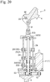
- FIG. 16 An example of the knee joint having been bent beyond 60° is shown in Fig. 16 to Fig. 20 .
- a lower end of the socket 200 is connected to the upper connection section 4 of the knee joint 100
- the foot section 300 is connected to the lower connection section 6 of the knee joint 100.
- the prosthetic leg is made up of the knee joint 100, the socket 200 and the foot section 300. It should be noted that for the connection of the upper connection section 4 and the socket 200, and the connection of the lower connection section 6 and the foot section 300, it is possible to use a similar attachment (not illustrated) to that in the conventional art.
- a repulsive force from the floor that has acted on the foot section is transmitted to the user by means of the elastic member 22, which means that it is possible to absorb impact at the time of grounding, and it is possible to reduce advancement of fatigue on the user.
- the energy that was stored in the elastic member 22 is released.
- the linear motion member 23 is caused to move and it is possible to extend the knee joint.
- the motor 11 is made to operate to bend the knee joint (refer, for example, to Fig. 12 ). In this way it is possible to store energy in the elastic member 22.
- crank mechanism 3 of this embodiment will be described in detail with further reference to Fig. 23 to Fig. 28 .
- Fig. 23 the structure of the knee joint of the previously described embodiment is schematically shown in Fig. 23 .
- the motor 11, speed change mechanism 12, and elastic member 22 are shown as a single actuator.
- the mechanism of Fig. 23 is further shown schematically in Fig. 24 .
- K Sin ⁇ ⁇ ⁇ C ⁇ o ⁇ s ⁇ ⁇
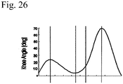
- Fig. 26 One example of change over time of knee angle in accordance with a person walking is shown in Fig. 26 .
- the knee angle changes between about 0° and 80°.
- a large change from a knee angle of about 80° to a knee angle of about 0° in a case such as this where a large angle change is necessary from a deep knee angle, then in order to cause rotation of the knee joint a large torque becomes necessary.
- a deep knee angle of about 80° it is possible to obtain a high reduction ratio. If this is done, there is the advantage that it is possible to provide a large torque to the knee joint without imposing a large load on the motor 11.
- FIG. 27 An example where offset amount between center of rotation of the crank mechanism 3 and the series elastic mechanism 2 has been changed is shown in Fig. 27 .
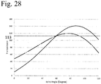
- a characteristic of reduction ratio after change in offset amount is shown by the solid line in Fig. 28 .
- the dot and dash line in Fig. 28 is a characteristic of the example of Fig. 25 .
Landscapes
- Health & Medical Sciences (AREA)
- Transplantation (AREA)
- Vascular Medicine (AREA)
- Life Sciences & Earth Sciences (AREA)
- Oral & Maxillofacial Surgery (AREA)
- Engineering & Computer Science (AREA)
- Biomedical Technology (AREA)
- Heart & Thoracic Surgery (AREA)
- Veterinary Medicine (AREA)
- Cardiology (AREA)
- Animal Behavior & Ethology (AREA)
- General Health & Medical Sciences (AREA)
- Public Health (AREA)
- Orthopedic Medicine & Surgery (AREA)
- Prostheses (AREA)
- Manipulator (AREA)
- Rehabilitation Tools (AREA)
Abstract
Description
- The present invention relates to a knee joint used in a prosthetic leg.
- Generally, a prosthetic leg is made up of a socket that is fixed to a section of a leg, a knee joint that is connected to a lower end of the socket, and a grounding part that is connected to a lower end of the knee joint. The knee joint, similarly to a human knee joint, is capable of extending and bending within a specified angular range.
- As a knee joint drive method, three methods exist, namely a passive method, an electronic control method, and an active method. With a passive method, the wearer moves the prosthetic leg, and the knee joint passively bends/extends using a damper of a hydraulic pressure cylinder or pneumatic cylinder and spring force etc. in accordance with movement of the prosthetic leg. With an electronic control method, movement resistance to bending and extension of the knee joint is adjusted using electronic control, and operation of the knee joint can be improved. One example of an electronic control method knee joint is shown in
patent publication 1 below. Also, with an active method, by actively controlling bending angle of the knee joint using a motor, knee joint movement for operations such as going up and down stairs is supported. - However, a conventional active method knee joint has a problem in that not only is cost high due to its complicated structure, it is also likely that the wearer will become tired due to the weight. In particular, with a conventional active method knee joint it is necessary to always operate a motor that is mounted on the knee joint, and since energy efficiency is not good a large capacity battery is required, which tends to make the knee joint large and heavy.
- On the other hand, an active method knee joint that moves a knee joint by converting linear motion from a series elastic actuator to rotational movement using a pulley is disclosed in
non-patent publication 1 below. With this technology, walking energy is utilized by using a spring of a series elastic actuator, and high energy efficiency is obtained compared to energy efficiency of a conventional active method knee joint. However, with this technology, in order to convert linear motion of the series elastic actuator to rotational motion of the knee, it results in a mechanism that rotates the knee by means of a belt having two pulleys fixed to elastic elements that move linearly. In order to prevent interference between the elastic elements that move linearly and the knee, it is necessary to arrange the belt and pulleys at a side surface of the knee joint. If this is done, then a need arises to use two belts in a single knee joint, in order to maintain balance. Accordingly, with this technology there is a problem that the mechanism becomes extremely complicated, and there are a lot of components. If an angle through which the knee joint can be moved (moveable range) is widened, then the belt and the pulley become large in size, and the knee joint becomes difficult to use due to the size and weight. Also, since a belt for moving the pulleys has a problem from a point of view of durability, there is a tendency for cost to increase easily because of maintenance and replacement of the belt. - Also, a structure for rotatably attaching a knee member to an upper end of a lower limb member, and attaching a foot member to a lower end of the lower limb member, is described in
patent publication 2 below. A projecting member is integrally formed with a side section of the knee member, and a linear actuator is attached between this projecting member and a lower part of a lower limb member. With this technology it is possible to supplement rotational movement of the knee member using drive force of this linear actuator. However, with this technology, because of the structure where the linear actuator is directly connected to the knee member without a reduction gear, there is problem in that a high load acts on the linear actuator in order to acquire high driving torque. -
- Patent Publication 1: Japanese patent laid-open No.
2004-167106 - Patent Publication 2: International patent application
2004/017872 - [non-patent publication 1]Elliott J. Rouse, Luke M. Mooney and Hugh M. Herr, "Clutchable series-elastic actuator: Implications for prosthetic knee design" October 9, 2014, doi: 10.1177/0278364914545673 The International Journal of Robotics Research November 2014 vol. 33 no. 13 1611-1625
- The present invention has been conceived based on the previously described situation. A main object of the present invention is to provide a knee joint that is capable of widening a moveable range, and that has good energy efficiency and is small and light weight.
- Means for solving the above described problem can be described as in the following aspects.
- A knee joint, comprising a drive section, a series elastic mechanism, and a crank mechanism, wherein the series elastic mechanism comprises a driven member, an elastic member, and a linear motion member, the drive section is configured to move the driven member, the elastic member is arranged between the driven member and the linear motion member, the linear motion member is configured to elastically move in at least one direction, in accordance with movement of the driven member, by means of the elastic member, and the crank mechanism is configured to convert linear motion of the linear motion member to rotational motion.
- The knee joint of
aspect 1, further comprising an upper connection section for connecting a socket and the knee joint, and wherein the crank mechanism is configured to cause rotational movement of the upper connection section in forward and backward directions. - The knee joint of
aspect 1 andaspect 2, further comprising a frame, wherein the linear motion member is capable of movement in at least one direction with respect to the frame. - The knee joint of
aspect 1 andaspect 2, further comprising a frame, wherein a rotational shaft of the crank mechanism is supported by the frame. - The knee joint of any one of
aspect 1 toaspect 4, wherein the drive section comprises a motor, a speed change mechanism, and a ball screw, and wherein the motor is configured to cause rotation of the ball screw in forward and backward directions by means of the speed change mechanism, and the driven member is configured to move linearly in response to rotation of the ball screw. - The knee joint of any one of
aspect 1 toaspect 5, wherein the linear motion member comprises a first contact section and a second contact section that are arranged facing each other, either side of the driven member, the elastic member comprises a first spring and a second spring, the first spring is arranged between the first contact section and the driven member, and the second spring is arranged between the second contact section and the driven member. - A prosthetic leg provided with the knee joint of any one of
aspect 1 toaspect 6. - According to the present invention, it is possible to provide a knee joint that has good energy efficiency, is small and light, and is capable of broadening movement range. Also, according to the present invention it is possible to provide a knee joint that is of an active type, but comparatively inexpensive.
-
-
Fig. 1 is a perspective drawing of a knee joint (bending angle=0°) of one embodiment of the present invention, in a state with a cover removed. -
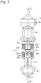
Fig. 2 is a front view ofFig. 1 . -
Fig. 3 is a left side view ofFig. 2 . -
Fig. 4 is a plan view ofFig. 2 . -
Fig. 5 is a cross sectional view taken along line A-A inFig. 3 . -
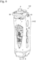
Fig. 6 is a perspective view of the knee joint ofFig. 1 in a state where the cover is attached. -
Fig. 7 is a front view ofFig. 6 . -
Fig. 8 is a left side view ofFig. 7 . -
Fig. 9 is a plan view ofFig. 7 . -
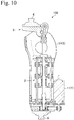
Fig. 10 is a cross sectional view taken along line A-A inFig. 8 . -
Fig. 11 is a perspective view of the knee joint ofFig. 1 , in a state where the bending angle is 60°. -
Fig. 12 is a front view ofFig. 11 . -
Fig. 13 is a left side view ofFig. 12 . -
Fig. 14 is a plan view ofFig. 12 . -
Fig. 15 is a cross sectional view taken along line A-A inFig. 13 . -
Fig. 16 is a perspective view of the knee joint ofFig. 1 , in a state where the bending angle is 120°. -
Fig. 17 is a front view ofFig. 16 . -
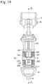
Fig. 18 is a left side view ofFig. 17 . -
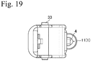
Fig. 19 is a plan view ofFig. 17 . -
Fig. 20 is a cross sectional view taken along line A-A inFig. 18 . -
Fig. 21 is a schematic explanatory drawing showing an example of having constructed a prosthetic leg using the knee joint ofFig. 1 . -
Fig. 22 is an explanatory drawing for describing operation of the prosthetic leg ofFig. 21 . -
Fig. 23 is an explanatory drawing for describing operation of a crank mechanism of the knee joint ofFig. 1 . -
Fig. 24 is a schematic explanatory drawings of the crank mechanism ofFig. 23 . -
Fig. 25 is a graph showing one example of characteristics of the crank mechanism ofFig. 24 , with the horizontal axis showing knee angle (degrees) and the vertical axis showing reduction ratio. -
Fig. 26 is a graph showing change in knee angle at the time of walking, with the horizontal axis showing time (arbitrary units) and the vertical axis showing knee angle (degrees). -
Fig. 27 is an explanatory drawing showing an example where offset amount of a series elastic mechanism with respect to a rotation shaft of a crank mechanism has changed. -
Fig. 28 is a graph showing a characteristic example of the crank mechanism ofFig. 27 overlapped on the characteristic example ofFig. 25 , with the horizontal axis showing knee angle (degrees) and the vertical axis showing reduction ratio. - A knee joint of one embodiment of the present invention will be described in the following with reference to the attached drawings (
Fig. 1 to Fig. 10 ). It should be noted that among these drawings,Fig. 1 to Fig. 5 show a state where a cover 51 (described later) of aframe 5 has been removed, whileFig. 6 to Fig. 10 show a state where thecover 51 has been attached. - The
knee joint 100 of this embodiment can constitute a prosthetic leg by combining asocket 200 and afoot section 300, as shown inFig. 21 (described later). The structure of theknee joint 100 of this embodiment will be described in the following. - The
knee joint 100 of this embodiment comprises adrive section 1, a serieselastic mechanism 2 and acrank mechanism 3. This knee joint 100 further comprises anupper connection section 4, aframe 5 and alower connection section 6. - The
drive section 1 comprises amotor 11, aspeed change mechanism 12 and a ball screw 13 (refer toFig. 5 ) Themotor 11 is configured to cause forward and backward rotation of theball screw 13 by means of thespeed change mechanism 12. Thedrive section 1 of this embodiment is provided with a battery (not illustrated), and it is possible to drive themotor 11 using electrical power supplied from this battery. However, it is also possible to have a configuration whereby themotor 11 is driven using an external power supply (for example, a commercial power supply). Also, thedrive section 1 is provided with sensors (not illustrated) that detect rotation angle of thecrank mechanism 3 and load on themotor 11, and it is possible to control torque and rotation angle of themotor 11 in accordance with outputs of these sensors. Themotor 11,speed change mechanism 12 and ball screw 13 of this embodiment are supported by theframe 5 via appropriate attachment members or shaft bearings. - The series
elastic mechanism 2 comprises a drivenmember 21, anelastic member 22, and alinear motion member 23. The serieselastic mechanism 2 of this embodiment also comprises aguide shaft 24 for guiding the drivenmember 21, and first andsecond contact sections linear motion member 23. - The driven
member 21 is configured to be moved along the guide shaft 24 (in the vertical direction inFig. 1 ) by drive force of thedrive section 1. More specifically, the drivenmember 21 of the serieselastic mechanism 2 of this embodiment is configured to reciprocate in a linear direction in response to rotation of theball screw 13 of thedrive section 1. - The
elastic member 22 is arranged between the drivenmember 21 and thelinear motion member 23. More specifically, theelastic member 22 of this embodiment comprises twofirst springs 221 and two second springs 222 (refer toFig. 1 andFig. 3 ). Thefirst springs 221 are arranged between the first contact section 231 (described later) of thelinear motion member 23 and the drivenmember 21, but in a state of not being fixed to these members. Thesecond springs 222 are arranged between the second contact section 232 (described later) of thelinear motion member 23 and the drivenmember 21, but in a state of not being fixed to these members. - The
linear motion member 23 is configured to elastically move in at least one direction, in accordance with movement of the drivenmember 21, by means of theelastic member 22. More specifically, as was mentioned previously, thelinear motion member 23 of this embodiment is provided with afirst contact section 231 and asecond contact section 232 that are arranged facing each other either side of the drivenmember 21, andlinear motion rods 233. Also, thefirst contact section 231 and thesecond contact section 232 are linked by struts 234 (refer toFig. 3 ). Eachstrut 234 penetrates through a drivenmember 21, and relative movement is possible between thestrut 234 and the drivenmember 21. Further, eachstrut 234 is arranged in a state respectively passing through the inside of afirst spring 221 and asecond spring 222 of theelastic member 22. With this example, bottom ends of thelinear motion rods 233 and upper ends of thestruts 234 are connected, and these parts constitute an integrated component. - There are two
guide shafts 24 in this embodiment, and they are respectively arranged so as to connect anupper base 52 and a lower base 53 (described later) of the frame 5 (refer toFig. 2 ). The twoguide shafts 24 are not fixed to the drivenmember 21, thefirst contact section 231 and thesecond contact section 233, and in this way it is possible for the drivenmember 21, thefirst contact section 231 and thesecond contact section 233 to move along an extending direction of the guide shafts 24 (that is, in the vertical direction inFig. 2 ). - With this embodiment, the
linear motion rods 233 of thelinear motion member 23 penetrate through theupper base 52 of theframe 5 and are fixed to an upper surface of the first contact section 231 (refer toFig. 2 andFig. 3 ), and reciprocate along the extending direction of the guide shafts 24 (that is, the vertical direction inFig. 1 ) in accordance with movement of thefirst contact section 231 and thesecond contact section 232. - The
crank mechanism 3 is configured to convert linear motion of thelinear motion member 23 to rotational motion. Thecrank mechanism 3 of this embodiment comprises a connectingrod 31, anarm member 32, and arotation shaft 33. - One end of the connecting
rod 31 is pin connected to the upper end of thelinear motion rods 233 of thelinear motion member 23 so as to enable mutual rotation. - The
arm member 32 is pin connected to the other end of the connectingrod 31 so as to enable mutual rotation. Also, thearm member 32 is made capable of swinging with therotation shaft 33 as a center. Theupper connection section 4 is attached to an upper part of thearm member 32. - With this embodiment, the
rotation shaft 33 is attached to the cover 51 (described later) of theframe 5, and relative position between therotation shaft 33 and theframe 5 is fixed. - The
upper connection section 4 is for connecting a socket 200 (refer toFig. 21 which will be described later) and theknee joint 100. Theupper connection section 4 realizes extension and bending operations of the prosthetic leg by rotational movement in forward and backward directions using thecrank mechanism 3. Theupper connection section 4 is also called a pyramid connector, and it is possible to connect to thesocket 200 using an existing method. - The
frame 5 of this embodiment comprises the cover 51 (refer toFig. 6 to Fig. 10 ), theupper base 52, and thelower base 53. With this embodiment, thelinear motion member 23 is made capable of movement in at least one direction with respect to the upper andlower bases Fig. 1 ). Also, with this embodiment, as was mentioned earlier, therotation shaft 33 of thecrank mechanism 3 is supported in a state capable of rotation by thecover 51 of theframe 5. Further, theupper base 52 and thelower base 53 are respectively fixed with respect to thecover 51, so that there is no relative movement. - The
lower connection section 6 is for connecting a foot section 300 (refer toFig. 21 which will be described later) and theknee joint 100. Thelower connection section 6 is fixed to thelower base 53 of theframe 5. Thelower connection section 6 is also called a pyramid connector, and it is possible to connect to thefoot section 300 using an existing method. - Next, operation of the
knee joint 100 of this embodiment will be described with further reference toFig. 11 to Fig. 22 . - In the description of this embodiment, the bending state shown in
Fig. 1 is defined as the angle of the knee joint being 0°. Operation to bend the bending angle of the knee joint from this state to 60° will be described in the following. - First, the
motor 11 of thedrive section 1 is made to rotate. If this is done, theball screw 13 is rotated by means of thespeed change mechanism 12, and the drivenmember 21 of the serieselastic mechanism 2 moves in one direction (with this example, the downward direction inFig. 1 ). - Once this happens, the driven
member 21 applies compression force to thesecond spring 222 of theelastic member 22, and thelinear motion member 23 is moved in one direction (with this example the downward direction inFig. 1 ), by mean of this spring. If thelinear motion member 23 is lowered by spring force, the connectingrod 31 of thecrank mechanism 3 is lowered, and as a result of that lowering thearm member 32 rotates with therotation shaft 33 as a center (refer toFig. 11 to Fig. 15 ). In this way it is possible to cause theupper connection section 4 to rotate by a desired angle. A knee angle of a person walking repeatedly changes from 0° (extended state) to 60° (bent state). Accordingly, after knee bending to 60° themotor 11 is reverse rotated, and the knee returns to the 0° extended state due to the application of compression force to thefirst spring 221. - Operation from a knee angle of 60° to 120° is operation at the time when the user is seated, sitting in the seiza style (sitting on their legs, or kneeling on the floor). At the time of sitting, in particularly, the motor is not operated, but in the case of standing from a seated state it is possible to provide assistance by operating the motor.
- An example of the knee joint having been bent beyond 60° is shown in
Fig. 16 to Fig. 20 . Similarly to the previous description, it is possible to cause bending of the knee joint up to about 120° (ideally up to about 140°) by further rotating thearm member 32 of thecrank mechanism 3. - By causing reverse rotation of the
motor 11 of thedrive section 1 it is possible to return the bending angle of the knee joint to the initial state (angle=0°). - With this embodiment, it is possible to dynamically change bending angle of the knee joint 100 by appropriately controlling torque, rotation speed or rotation angle of the
motor 11. With usage of the prosthetic leg, for example, when climbing stairs or getting up from a chair, it is possible to support actions of the prosthetic leg user (operations of walking, going up stairs by advancing one step higher on each step with left and right legs alternatively, and standing) by actively controlling rotation angle of the knee joint using drive force of thedrive section 1. - Also, with the technology described in previously mentioned
non-patent publication 1, there were the following problems. - a structure for converting linear motion of an elastic mechanism to rotational motion of a knee is extremely complex, and has many components. Accordingly, it becomes heavy;
- if movable angle of the knee joint is widened, a pulley is made large in size;
- in order to prevent interference between component parts (elastic elements) and the knee, it is necessary to arrange a pulley at a side surface of the prosthetic leg. If this is done, then in order to maintain balance a need arises to use two pulley mechanisms in a single prosthetic leg (a single pulley mechanism comprises two pulleys, a single connecting cable, and related components).
- pulley cables have a problem with regard to durability, and it s easy for maintenance costs to become high.
- By contrast, according to the knee joint of this embodiment that has been described, it is possible to demonstrate the following advantages:
- since a crank mechanism is used, it is possible to restrict size increase of the knee joint overall even when moveable angle of the knee joint is widened;
- since it is possible to use a single crank mechanism that is small and lightweight instead of the pulley mechanism, it is possible to provide a small and lightweight prosthetic leg;
- a crank mechanism generally has high durability compared to a pulley, and so it is possible to keep maintenance costs low.
- Next, an example of the knee joint of this embodiment having been fitted to a user will be described with reference to
Fig. 21 . With this example, a lower end of thesocket 200 is connected to theupper connection section 4 of the knee joint 100, and thefoot section 300 is connected to thelower connection section 6 of theknee joint 100. With the illustrated example, the prosthetic leg is made up of the knee joint 100, thesocket 200 and thefoot section 300. It should be noted that for the connection of theupper connection section 4 and thesocket 200, and the connection of thelower connection section 6 and thefoot section 300, it is possible to use a similar attachment (not illustrated) to that in the conventional art. - Next, a walking operation using the prosthetic leg of this embodiment will be described further referencing
Fig. 22 . It should be noted that in this drawing reference numeral L has been attached to the prosthetic leg. - If the foot section of the prosthetic leg lands on the floor, then with the knee joint of this embodiment a pressing force is applied downwards on the
linear motion member 23 from thesocket 200 via thecrank mechanism 3, and as a result thefirst spring 221 of theelastic member 22 is elastically deformed and that energy is stored. However, since thelinear motion member 23 is attached to theball screw 13 via the drivenmember 21, it is possible to produce a resistance force against movement of the drivenmember 21 by causing the motor to act in a direction opposite to the direction in which the ball screw rotates, and it is possible to conserve the energy of theelastic member 22. - Here, with this embodiment, by appropriately setting spring force and initial position of the
elastic member 22, it is possible to set bending angle (bending angle due to passive deformation) of the knee joint for the time points where the foot section is grounded (Fig. 22 (a) and (b) ) to about 20°. If this is done, there are the advantages that it is possible to realize a knee bending angle of about 20° for the purpose of impact absorption at the time of grounding that is innate to people, and it is possible to improve usage sensitivity for the user. - Also, with this embodiment, a repulsive force from the floor that has acted on the foot section is transmitted to the user by means of the
elastic member 22, which means that it is possible to absorb impact at the time of grounding, and it is possible to reduce advancement of fatigue on the user. - Continuing on, during a walking operation, the energy that was stored in the
elastic member 22 is released. As a result, thelinear motion member 23 is caused to move and it is possible to extend the knee joint. - After that, with this embodiment, the
motor 11 is made to operate to bend the knee joint (refer, for example, toFig. 12 ). In this way it is possible to store energy in theelastic member 22. - If walking advances further, with this embodiment the
motor 11 is driven in a reverse direction, and the knee joint is extended. Here, with this embodiment, energy that has been stored in theelastic member 22 supplements the extension operation of the knee joint and so it is possible to reduce the drive force required in themotor 11. Accordingly, with this embodiment battery size reduction and long battery life can be expected. - Also, in a case where friction resistance between the
ball screw 13 and thelinear motion member 23 has been set low, there is the advantage that it is possible to perform power regeneration with themotor 11, utilizing elastic force of the previously describedelastic member 22. - Next, operation of the
crank mechanism 3 of this embodiment will be described in detail with further reference toFig. 23 to Fig. 28 . - First of all, for the purposes of operational description, the structure of the knee joint of the previously described embodiment is schematically shown in
Fig. 23 . In this diagram, themotor 11,speed change mechanism 12, andelastic member 22 are shown as a single actuator. The mechanism ofFig. 23 is further shown schematically inFig. 24 . - A reduction ratio of the knee joint that uses this crank
mechanism 3 is expressed by the following equation.
Here, - Nm: number of teeth of a
motor 11 side pulley of thespeed change mechanism 12; - Nb: number of teeth of a
ball screw 13 side pulley of thespeed change mechanism 12; - Lb: lead of the
ball screw 13; - R: radius of gyration of the
arm member 32; - K: reduction coefficient due to crank mechanism.
- Here, since each variable other than K is considered to be a constant in this description, detailed description will be omitted. The reduction coefficient K of the crank mechanism is expressed as follows.

Here, - α: angle of
arm member 32 with respect to the vertical direction (vertical direction inFig. 24 ); - β: angle of connecting
rod 31 with respect to vertical direction (vertical direction inFig. 24 ). - Due to the influence of reduction coefficient K, the reduction ratio of the crank mechanism becomes as shown in
Fig. 25 . With this characteristic, reduction ratio changes in accordance with change in knee angle, and reduction ratio becomes maximum around knee angle α=80° Specifically, with the crank mechanism of this embodiment it is possible to move the knee joint at a different reduction ratio in accordance with change is knee angle. - One example of change over time of knee angle in accordance with a person walking is shown in
Fig. 26 . As shown in this drawing, during walking the knee angle changes between about 0° and 80°. Also, for example, when going up and down stairs or standing up from a chair, there is instantaneously a large change from a knee angle of about 80° to a knee angle of about 0°. In a case such as this where a large angle change is necessary from a deep knee angle, then in order to cause rotation of the knee joint a large torque becomes necessary. With this embodiment, for a deep knee angle of about 80°, it is possible to obtain a high reduction ratio. If this is done, there is the advantage that it is possible to provide a large torque to the knee joint without imposing a large load on themotor 11. - Also, in the case of a quick pace, with a knee joint, while a fast rotation speed is required with a shallow knee angle, high torque is not required. With the crank mechanism of this embodiment, in the case of a shallow knee angle (for example, 0° to 20°), since there is a low reduction ratio there is the advantage that increasing rotation speed of the knee joint becomes easy.
- Conversely, in the case where a pulley mechanism (refer to previously described non-patent publication 1) is used instead of the crank mechanism, then since a reduction coefficient K does not exist in the pulley mechanism, reduction ratio with the pulley mechanism becomes constant regardless of knee angle. Accordingly, in the event that large torque is necessary, a large load is liable to arise in the motor. Also, in the case where a speed change mechanism is not used (refer to previously described patent publication 2), a similar problem arises. Contrasting with this, with the knee joint of this embodiment, by using the crank mechanism there is the advantage that it is possible to reconcile high torque and high rotation speed.
- An example where offset amount between center of rotation of the
crank mechanism 3 and the serieselastic mechanism 2 has been changed is shown inFig. 27 . A characteristic of reduction ratio after change in offset amount is shown by the solid line inFig. 28 . The dot and dash line inFig. 28 is a characteristic of the example ofFig. 25 . As will be understood from this drawing, by changing offset amount it is possible to adjust a relationship between knee angle α and reduction ratio. Accordingly, according to this embodiment there is the advantage that it becomes possible to obtain maximum torque with the required knee angle, by adjusting offset amount. - It should be noted that the content of the present invention is not limited by the previously described embodiments. The present invention may additionally be subject to various changes to the basic structure, within a range disclosed in the scope of the patent claims.
-
- 1 drive section
- 11 motor
- 12 speed change mechanism
- 13 ball screw
- 2 series elastic mechanism
- 21 driven member
- 22 elastic member
- 221 first spring
- 222 second spring
- 23 linear motion member
- 231 first contact section
- 232 second contact section
- 233 linear motion rod
- 24 guide shaft
- 3 crank mechanism
- 31 connecting rod
- 32 arm member
- 33 rotation shaft
- 4 upper connection section
- 5 frame
- 51 cover
- 52 upper base
- 53 lower base
- 6 lower connection section
- 100 knee joint
- 200 socket
- 300 foot section
- L prosthetic leg
Claims (8)
- A knee joint, comprising a drive section, a series elastic mechanism, and a crank mechanism, wherein:the series elastic mechanism comprises a driven member, an elastic member and a linear motion member;the drive section is configured to move the driven member;the elastic member is arranged between the driven member and the linear motion member;the linear motion member is configured to elastically move in at least one direction, in accordance with movement of the driven member, by means of the elastic member; andthe crank mechanism is configured to convert linear motion of the linear motion member to rotational motion.
- The knee joint of claim 1, further comprising:an upper connection section for connecting a socket and the knee joint, and whereinthe crank mechanism is configured to cause rotational movement of the upper connection section in forward and backward directions.
- The knee joint of claim 1 or claim 2, further comprising:a frame, whereinthe linear motion member is capable of movement in at least one direction with respect the frame.
- The knee joint of claim 1 or claim 2, further comprising:a frame, whereina rotational shaft of the crank mechanism is supported by the frame.
- The knee joint of any one of claim 1 to claim 4, wherein:the drive section comprises a motor, a speed change mechanism and a ball screw, and whereinthe motor is configured to cause rotation of the ball screw in forward and backward directions by means of the speed change mechanism, andthe driven member is configured to move linearly in response to rotation of the ball screw.
- The knee joint of any one of claim 1 to claim 5, wherein:the linear motion member comprises a first contact section and a second contact section that are arranged facing each other, either side of the driven member;the elastic member comprises a first spring and a second spring;the first spring is arranged between the first contact section and the driven member; andthe second spring is arranged between the second contact section and the driven member.
- The knee joint of any one of claim 1 to claim 6, wherein:
a reduction ratio of the crank mechanism is configured to change in accordance with rotation angle for the rotation motion. - A prosthetic leg provided with the knee joint of any one of claim 1 to claim 7.
Applications Claiming Priority (2)
| Application Number | Priority Date | Filing Date | Title |
|---|---|---|---|
| JP2016219496 | 2016-11-10 | ||
| PCT/JP2017/031190 WO2018087997A1 (en) | 2016-11-10 | 2017-08-30 | Knee joint |
Publications (4)
| Publication Number | Publication Date |
|---|---|
| EP3539514A1 true EP3539514A1 (en) | 2019-09-18 |
| EP3539514A4 EP3539514A4 (en) | 2020-05-06 |
| EP3539514C0 EP3539514C0 (en) | 2023-07-12 |
| EP3539514B1 EP3539514B1 (en) | 2023-07-12 |
Family
ID=62110261
Family Applications (1)
| Application Number | Title | Priority Date | Filing Date |
|---|---|---|---|
| EP17869954.2A Active EP3539514B1 (en) | 2016-11-10 | 2017-08-30 | Knee joint |
Country Status (5)
| Country | Link |
|---|---|
| US (2) | US11696840B2 (en) |
| EP (1) | EP3539514B1 (en) |
| JP (2) | JP6762576B2 (en) |
| CN (2) | CN114209479A (en) |
| WO (1) | WO2018087997A1 (en) |
Cited By (1)
| Publication number | Priority date | Publication date | Assignee | Title |
|---|---|---|---|---|
| US12263101B2 (en) | 2019-03-29 | 2025-04-01 | Honda Motor Co., Ltd. | Joint device |
Families Citing this family (18)
| Publication number | Priority date | Publication date | Assignee | Title |
|---|---|---|---|---|
| JP6762576B2 (en) * | 2016-11-10 | 2020-09-30 | 国立大学法人 東京大学 | Knee joint |
| WO2019173751A1 (en) * | 2018-03-08 | 2019-09-12 | Apptronik, Inc. | Exoskeleton device with improved actuation system |
| EP3821220B1 (en) | 2018-08-22 | 2024-11-13 | University of Utah Research Foundation | Force and torque sensor for prosthetic and orthopedic devices |
| US12070398B2 (en) | 2018-08-28 | 2024-08-27 | University Of Utah Research Foundation | Variable transmission for assistive prosthesis device |
| US20220323242A1 (en) * | 2019-08-29 | 2022-10-13 | Honda Motor Co., Ltd. | Joint device |
| EP4032508B1 (en) * | 2019-09-17 | 2025-03-26 | Bionicm Inc. | Assist device and artificial limb |
| WO2021130651A1 (en) * | 2019-12-22 | 2021-07-01 | Zeynolabedin Soleymani | A passive prosthetic knee |
| US12048668B2 (en) | 2020-03-20 | 2024-07-30 | The University Of Utah Research Foundation | Self-aligning mechanisms in passive and powered exoskeletons |
| BR112022025252A2 (en) * | 2020-06-12 | 2022-12-27 | Honda Motor Co Ltd | JOINT DEVICE |
| US12521297B1 (en) | 2020-10-09 | 2026-01-13 | Apptronik, Inc. | Enhanced transparency exoskeleton |
| KR102265666B1 (en) * | 2020-10-27 | 2021-06-16 | 금오공과대학교 산학협력단 | Muscle force assisting device of the exoskeleton robot |
| WO2022145545A1 (en) * | 2020-12-30 | 2022-07-07 | 근로복지공단 | Hybrid knee prosthesis having multi-functional rotary hydraulic cylinder |
| JP7674857B2 (en) * | 2021-03-02 | 2025-05-12 | 本田技研工業株式会社 | Coupling Device |
| JP7733982B2 (en) * | 2021-03-02 | 2025-09-04 | 本田技研工業株式会社 | Coupling Device |
| WO2023017351A1 (en) * | 2021-08-09 | 2023-02-16 | Fondazione Istituto Italiano Di Tecnologia | Joint prosthesis |
| CN116211555B (en) * | 2023-05-06 | 2023-08-29 | 浙江强脑科技有限公司 | Artificial limb |
| KR102885009B1 (en) * | 2023-08-28 | 2025-11-17 | 근로복지공단 | Hybrid-type knee joint support device |
| US12433771B1 (en) * | 2025-03-17 | 2025-10-07 | University Of Utah Research Foundation | Powered prosthesis with torque-sensitive actuation |
Family Cites Families (34)
| Publication number | Priority date | Publication date | Assignee | Title |
|---|---|---|---|---|
| US4206519A (en) * | 1978-08-08 | 1980-06-10 | Chas. A. Blatchford & Sons Limited | Stabilized artificial knee mechanism |
| DE4232602C2 (en) * | 1992-09-29 | 1995-01-12 | Bock Orthopaed Ind | Joint in orthopedic prostheses and orthoses |
| FR2735018B1 (en) * | 1995-06-09 | 1997-07-11 | Proteval | PNEUMATIC PROSTHETIC PART FOR THE KNEE JOINT |
| US5650704A (en) * | 1995-06-29 | 1997-07-22 | Massachusetts Institute Of Technology | Elastic actuator for precise force control |
| JP3245828B2 (en) * | 1998-04-03 | 2002-01-15 | 株式会社ナブコ | Prosthesis with extension assist mechanism |
| US6673117B1 (en) * | 2000-11-30 | 2004-01-06 | Adam Soss | Single axis knee joint assembly |
| AU2003236750B2 (en) * | 2002-08-22 | 2006-08-10 | Victhom Human Bionics Inc. | Actuated leg prosthesis for above-knee amputees |
| US7736394B2 (en) * | 2002-08-22 | 2010-06-15 | Victhom Human Bionics Inc. | Actuated prosthesis for amputees |
| JP4129862B2 (en) * | 2002-08-30 | 2008-08-06 | 本田技研工業株式会社 | Prosthetic joint device |
| TWI276430B (en) * | 2002-11-21 | 2007-03-21 | Nabtesco Corp | Prosthetic limb having knee braking function |
| JP3938900B2 (en) | 2002-11-21 | 2007-06-27 | ナブテスコ株式会社 | Prosthetic leg with flexible knee braking function |
| DE202004008014U1 (en) * | 2004-05-18 | 2004-09-09 | Teko Automation, Mensch Und Technik Gmbh | Swing phase control device |
| US8500823B2 (en) * | 2005-03-31 | 2013-08-06 | Massachusetts Institute Of Technology | Powered artificial knee with agonist-antagonist actuation |
| US20060249315A1 (en) * | 2005-03-31 | 2006-11-09 | Massachusetts Institute Of Technology | Artificial human limbs and joints employing actuators, springs, and variable-damper elements |
| US20070043449A1 (en) | 2005-03-31 | 2007-02-22 | Massachusetts Institute Of Technology | Artificial ankle-foot system with spring, variable-damping, and series-elastic actuator components |
| US20070162152A1 (en) * | 2005-03-31 | 2007-07-12 | Massachusetts Institute Of Technology | Artificial joints using agonist-antagonist actuators |
| US20070123997A1 (en) | 2005-03-31 | 2007-05-31 | Massachusetts Institute Of Technology | Exoskeletons for running and walking |
| US7485152B2 (en) * | 2005-08-26 | 2009-02-03 | The Ohio Willow Wood Company | Prosthetic leg having electronically controlled prosthetic knee with regenerative braking feature |
| JP2008023234A (en) * | 2006-07-25 | 2008-02-07 | Tokyo Institute Of Technology | Powered walking support device |
| US8435309B2 (en) * | 2007-01-05 | 2013-05-07 | Victhom Human Bionics | Joint actuation mechanism for a prosthetic and/or orthotic device having a compliant transmission |
| US8974543B2 (en) * | 2008-04-30 | 2015-03-10 | Rizzoli Ortopedia S.P.A. | Automatic prosthesis for above-knee amputees |
| DE102008029494A1 (en) * | 2008-06-20 | 2009-12-24 | Bernd Krieg | Uniaxial brake knee joint for above-knee prosthesis for above-knee amputee, has joint middle part for receiving vertically slidable guide rod with lower end, and joint lower part including through hole for releasing swing phase control |
| KR100924842B1 (en) * | 2008-07-04 | 2009-11-02 | 연세대학교 산학협력단 | Control Method of Active Lower Limb Orthosis for Preventing Foot and Foot Disturbance in Paralyzed Patients |
| JP4744589B2 (en) * | 2008-12-17 | 2011-08-10 | 本田技研工業株式会社 | Walking assist device and its control device |
| CN101496751B (en) * | 2009-03-11 | 2011-08-10 | 河北工业大学 | Active mode human leg prosthetic limb |
| FR2968538B1 (en) * | 2010-12-09 | 2013-01-04 | Pierre Chabloz | PROSTHETIC FOR LOWER MEMBER |
| WO2013172968A1 (en) * | 2012-05-15 | 2013-11-21 | Vanderbilt University | Stair ascent and descent control for powered lower limb devices |
| WO2014151584A1 (en) * | 2013-03-15 | 2014-09-25 | Alterg, Inc. | Orthotic device drive system and method |
| CN103271783B (en) * | 2013-05-16 | 2015-04-15 | 清华大学 | Artificial limb knee joint with assistance function |
| DE102014000020B4 (en) * | 2014-01-03 | 2021-03-11 | Ottobock Se & Co. Kgaa | Prosthetic knee joint |
| CA2969884C (en) * | 2014-12-08 | 2023-03-28 | Rehabilitation Institute Of Chicago | Powered and passive assistive device and related methods |
| JP6762576B2 (en) * | 2016-11-10 | 2020-09-30 | 国立大学法人 東京大学 | Knee joint |
| US12070398B2 (en) * | 2018-08-28 | 2024-08-27 | University Of Utah Research Foundation | Variable transmission for assistive prosthesis device |
| US20220323242A1 (en) * | 2019-08-29 | 2022-10-13 | Honda Motor Co., Ltd. | Joint device |
-
2017
- 2017-08-30 JP JP2018550042A patent/JP6762576B2/en active Active
- 2017-08-30 EP EP17869954.2A patent/EP3539514B1/en active Active
- 2017-08-30 WO PCT/JP2017/031190 patent/WO2018087997A1/en not_active Ceased
- 2017-08-30 CN CN202111598448.4A patent/CN114209479A/en active Pending
- 2017-08-30 CN CN201780068657.3A patent/CN109982665B/en active Active
- 2017-08-30 US US16/348,435 patent/US11696840B2/en active Active
-
2020
- 2020-09-02 JP JP2020147229A patent/JP6927616B2/en active Active
-
2023
- 2023-05-24 US US18/323,132 patent/US20230310181A1/en active Pending
Cited By (1)
| Publication number | Priority date | Publication date | Assignee | Title |
|---|---|---|---|---|
| US12263101B2 (en) | 2019-03-29 | 2025-04-01 | Honda Motor Co., Ltd. | Joint device |
Also Published As
| Publication number | Publication date |
|---|---|
| CN114209479A (en) | 2022-03-22 |
| EP3539514C0 (en) | 2023-07-12 |
| JP6927616B2 (en) | 2021-09-01 |
| CN109982665A (en) | 2019-07-05 |
| JP2020199292A (en) | 2020-12-17 |
| WO2018087997A1 (en) | 2018-05-17 |
| EP3539514A4 (en) | 2020-05-06 |
| US20230310181A1 (en) | 2023-10-05 |
| US11696840B2 (en) | 2023-07-11 |
| JP6762576B2 (en) | 2020-09-30 |
| US20210298922A1 (en) | 2021-09-30 |
| EP3539514B1 (en) | 2023-07-12 |
| CN109982665B (en) | 2022-01-04 |
| JPWO2018087997A1 (en) | 2019-09-26 |
Similar Documents
| Publication | Publication Date | Title |
|---|---|---|
| EP3539514B1 (en) | Knee joint | |
| US9161880B2 (en) | Walking assist device | |
| EP3475033B1 (en) | Exoskeleton and master | |
| EP3365144B1 (en) | Humanoid robot foot comprising an active variable stiffness mechanism | |
| US20170181917A1 (en) | Assist device, swinging joint device, linear motion variable rigidity unit, and machine tool | |
| US20140330431A1 (en) | Joint Torque Augmentation System and Method for Gait Assistance | |
| US20160113831A1 (en) | System and Method of Bidirectional Compliant Joint Torque Actuation | |
| CA3026301C (en) | Body lightening system for gait training | |
| US20160023350A1 (en) | Gravitational Load Support System | |
| CN115741643B (en) | Active and passive combined knee exoskeleton robot | |
| US10898753B2 (en) | Treadmills having adjustable surface stiffness | |
| CN112388617B (en) | Lower limb exoskeleton robot | |
| CN110053683B (en) | A robot calf foot with pressure-controlled motion mode switching | |
| US20140259798A1 (en) | Systems and Methods for Gravitational Load Support | |
| US20200237592A1 (en) | Lifting seat | |
| CN105342811B (en) | Support member and the self-adapting seat device with the support member | |
| CN113386108A (en) | Walking robot | |
| KR101653100B1 (en) | A leg action assist apparatus with Reverse drive is easy | |
| TWI857902B (en) | Mixed-drive back-assist exoskeleton system | |
| TR202022508A2 (en) | A transfemoral prosthesis for walking, sitting up, climbing stairs. | |
| CN223231005U (en) | Drive mechanism | |
| EP4644051A1 (en) | Ankle exoskeleton | |
| Verburg et al. | Development of a Variable Stiffness Mechanism with a Linear Output for Exosuit Integration | |
| CN120131374B (en) | Lower limb exoskeleton's shank structure and exoskeleton robot | |
| CN114654453B (en) | Exoskeleton wearable shoulder booster device |
Legal Events
| Date | Code | Title | Description |
|---|---|---|---|
| STAA | Information on the status of an ep patent application or granted ep patent |
Free format text: STATUS: THE INTERNATIONAL PUBLICATION HAS BEEN MADE |
|
| PUAI | Public reference made under article 153(3) epc to a published international application that has entered the european phase |
Free format text: ORIGINAL CODE: 0009012 |
|
| STAA | Information on the status of an ep patent application or granted ep patent |
Free format text: STATUS: REQUEST FOR EXAMINATION WAS MADE |
|
| 17P | Request for examination filed |
Effective date: 20190529 |
|
| AK | Designated contracting states |
Kind code of ref document: A1 Designated state(s): AL AT BE BG CH CY CZ DE DK EE ES FI FR GB GR HR HU IE IS IT LI LT LU LV MC MK MT NL NO PL PT RO RS SE SI SK SM TR |
|
| AX | Request for extension of the european patent |
Extension state: BA ME |
|
| DAV | Request for validation of the european patent (deleted) | ||
| DAX | Request for extension of the european patent (deleted) | ||
| A4 | Supplementary search report drawn up and despatched |
Effective date: 20200407 |
|
| RIC1 | Information provided on ipc code assigned before grant |
Ipc: A61F 2/50 20060101ALN20200401BHEP Ipc: A61H 3/00 20060101ALN20200401BHEP Ipc: A61F 2/70 20060101ALI20200401BHEP Ipc: A61F 2/64 20060101AFI20200401BHEP Ipc: A61F 2/68 20060101ALN20200401BHEP |
|
| STAA | Information on the status of an ep patent application or granted ep patent |
Free format text: STATUS: EXAMINATION IS IN PROGRESS |
|
| 17Q | First examination report despatched |
Effective date: 20210318 |
|
| RIC1 | Information provided on ipc code assigned before grant |
Ipc: A61H 3/00 20060101ALN20221213BHEP Ipc: A61F 2/68 20060101ALN20221213BHEP Ipc: A61F 2/50 20060101ALN20221213BHEP Ipc: A61F 2/76 20060101ALI20221213BHEP Ipc: A61F 2/70 20060101ALI20221213BHEP Ipc: A61F 2/64 20060101AFI20221213BHEP |
|
| GRAP | Despatch of communication of intention to grant a patent |
Free format text: ORIGINAL CODE: EPIDOSNIGR1 |
|
| STAA | Information on the status of an ep patent application or granted ep patent |
Free format text: STATUS: GRANT OF PATENT IS INTENDED |
|
| INTG | Intention to grant announced |
Effective date: 20230127 |
|
| GRAS | Grant fee paid |
Free format text: ORIGINAL CODE: EPIDOSNIGR3 |
|
| GRAA | (expected) grant |
Free format text: ORIGINAL CODE: 0009210 |
|
| STAA | Information on the status of an ep patent application or granted ep patent |
Free format text: STATUS: THE PATENT HAS BEEN GRANTED |
|
| AK | Designated contracting states |
Kind code of ref document: B1 Designated state(s): AL AT BE BG CH CY CZ DE DK EE ES FI FR GB GR HR HU IE IS IT LI LT LU LV MC MK MT NL NO PL PT RO RS SE SI SK SM TR |
|
| REG | Reference to a national code |
Ref country code: CH Ref legal event code: EP |
|
| REG | Reference to a national code |
Ref country code: DE Ref legal event code: R096 Ref document number: 602017071322 Country of ref document: DE |
|
| REG | Reference to a national code |
Ref country code: IE Ref legal event code: FG4D |
|
| U01 | Request for unitary effect filed |
Effective date: 20230712 |
|
| U07 | Unitary effect registered |
Designated state(s): AT BE BG DE DK EE FI FR IT LT LU LV MT NL PT SE SI Effective date: 20230719 |
|
| U20 | Renewal fee for the european patent with unitary effect paid |
Year of fee payment: 7 Effective date: 20230828 |
|
| REG | Reference to a national code |
Ref country code: LT Ref legal event code: MG9D |
|
| PG25 | Lapsed in a contracting state [announced via postgrant information from national office to epo] |
Ref country code: GR Free format text: LAPSE BECAUSE OF FAILURE TO SUBMIT A TRANSLATION OF THE DESCRIPTION OR TO PAY THE FEE WITHIN THE PRESCRIBED TIME-LIMIT Effective date: 20231013 |
|
| PG25 | Lapsed in a contracting state [announced via postgrant information from national office to epo] |
Ref country code: ES Free format text: LAPSE BECAUSE OF FAILURE TO SUBMIT A TRANSLATION OF THE DESCRIPTION OR TO PAY THE FEE WITHIN THE PRESCRIBED TIME-LIMIT Effective date: 20230712 |
|
| PG25 | Lapsed in a contracting state [announced via postgrant information from national office to epo] |
Ref country code: IS Free format text: LAPSE BECAUSE OF FAILURE TO SUBMIT A TRANSLATION OF THE DESCRIPTION OR TO PAY THE FEE WITHIN THE PRESCRIBED TIME-LIMIT Effective date: 20231112 |
|
| PG25 | Lapsed in a contracting state [announced via postgrant information from national office to epo] |
Ref country code: RS Free format text: LAPSE BECAUSE OF FAILURE TO SUBMIT A TRANSLATION OF THE DESCRIPTION OR TO PAY THE FEE WITHIN THE PRESCRIBED TIME-LIMIT Effective date: 20230712 Ref country code: NO Free format text: LAPSE BECAUSE OF FAILURE TO SUBMIT A TRANSLATION OF THE DESCRIPTION OR TO PAY THE FEE WITHIN THE PRESCRIBED TIME-LIMIT Effective date: 20231012 Ref country code: IS Free format text: LAPSE BECAUSE OF FAILURE TO SUBMIT A TRANSLATION OF THE DESCRIPTION OR TO PAY THE FEE WITHIN THE PRESCRIBED TIME-LIMIT Effective date: 20231112 Ref country code: HR Free format text: LAPSE BECAUSE OF FAILURE TO SUBMIT A TRANSLATION OF THE DESCRIPTION OR TO PAY THE FEE WITHIN THE PRESCRIBED TIME-LIMIT Effective date: 20230712 Ref country code: GR Free format text: LAPSE BECAUSE OF FAILURE TO SUBMIT A TRANSLATION OF THE DESCRIPTION OR TO PAY THE FEE WITHIN THE PRESCRIBED TIME-LIMIT Effective date: 20231013 Ref country code: ES Free format text: LAPSE BECAUSE OF FAILURE TO SUBMIT A TRANSLATION OF THE DESCRIPTION OR TO PAY THE FEE WITHIN THE PRESCRIBED TIME-LIMIT Effective date: 20230712 |
|
| PG25 | Lapsed in a contracting state [announced via postgrant information from national office to epo] |
Ref country code: PL Free format text: LAPSE BECAUSE OF FAILURE TO SUBMIT A TRANSLATION OF THE DESCRIPTION OR TO PAY THE FEE WITHIN THE PRESCRIBED TIME-LIMIT Effective date: 20230712 |
|
| REG | Reference to a national code |
Ref country code: CH Ref legal event code: PL |
|
| REG | Reference to a national code |
Ref country code: DE Ref legal event code: R097 Ref document number: 602017071322 Country of ref document: DE |
|
| PG25 | Lapsed in a contracting state [announced via postgrant information from national office to epo] |
Ref country code: SM Free format text: LAPSE BECAUSE OF FAILURE TO SUBMIT A TRANSLATION OF THE DESCRIPTION OR TO PAY THE FEE WITHIN THE PRESCRIBED TIME-LIMIT Effective date: 20230712 Ref country code: RO Free format text: LAPSE BECAUSE OF FAILURE TO SUBMIT A TRANSLATION OF THE DESCRIPTION OR TO PAY THE FEE WITHIN THE PRESCRIBED TIME-LIMIT Effective date: 20230712 Ref country code: CZ Free format text: LAPSE BECAUSE OF FAILURE TO SUBMIT A TRANSLATION OF THE DESCRIPTION OR TO PAY THE FEE WITHIN THE PRESCRIBED TIME-LIMIT Effective date: 20230712 Ref country code: SK Free format text: LAPSE BECAUSE OF FAILURE TO SUBMIT A TRANSLATION OF THE DESCRIPTION OR TO PAY THE FEE WITHIN THE PRESCRIBED TIME-LIMIT Effective date: 20230712 Ref country code: CH Free format text: LAPSE BECAUSE OF NON-PAYMENT OF DUE FEES Effective date: 20230831 Ref country code: MC Free format text: LAPSE BECAUSE OF FAILURE TO SUBMIT A TRANSLATION OF THE DESCRIPTION OR TO PAY THE FEE WITHIN THE PRESCRIBED TIME-LIMIT Effective date: 20230712 |
|
| PLBE | No opposition filed within time limit |
Free format text: ORIGINAL CODE: 0009261 |
|
| STAA | Information on the status of an ep patent application or granted ep patent |
Free format text: STATUS: NO OPPOSITION FILED WITHIN TIME LIMIT |
|
| REG | Reference to a national code |
Ref country code: IE Ref legal event code: MM4A |
|
| 26N | No opposition filed |
Effective date: 20240415 |
|
| PG25 | Lapsed in a contracting state [announced via postgrant information from national office to epo] |
Ref country code: IE Free format text: LAPSE BECAUSE OF NON-PAYMENT OF DUE FEES Effective date: 20230830 |
|
| PG25 | Lapsed in a contracting state [announced via postgrant information from national office to epo] |
Ref country code: IE Free format text: LAPSE BECAUSE OF NON-PAYMENT OF DUE FEES Effective date: 20230830 |
|
| U20 | Renewal fee for the european patent with unitary effect paid |
Year of fee payment: 8 Effective date: 20240816 |
|
| PG25 | Lapsed in a contracting state [announced via postgrant information from national office to epo] |
Ref country code: CY Free format text: LAPSE BECAUSE OF FAILURE TO SUBMIT A TRANSLATION OF THE DESCRIPTION OR TO PAY THE FEE WITHIN THE PRESCRIBED TIME-LIMIT; INVALID AB INITIO Effective date: 20170830 |
|
| PG25 | Lapsed in a contracting state [announced via postgrant information from national office to epo] |
Ref country code: HU Free format text: LAPSE BECAUSE OF FAILURE TO SUBMIT A TRANSLATION OF THE DESCRIPTION OR TO PAY THE FEE WITHIN THE PRESCRIBED TIME-LIMIT; INVALID AB INITIO Effective date: 20170830 |
|
| U20 | Renewal fee for the european patent with unitary effect paid |
Year of fee payment: 9 Effective date: 20250822 |
|
| PGFP | Annual fee paid to national office [announced via postgrant information from national office to epo] |
Ref country code: GB Payment date: 20250812 Year of fee payment: 9 |
|
| PG25 | Lapsed in a contracting state [announced via postgrant information from national office to epo] |
Ref country code: TR Free format text: LAPSE BECAUSE OF FAILURE TO SUBMIT A TRANSLATION OF THE DESCRIPTION OR TO PAY THE FEE WITHIN THE PRESCRIBED TIME-LIMIT Effective date: 20230712 |