EP3539445A1 - Method for manufacturing a tip housing - Google Patents
Method for manufacturing a tip housing Download PDFInfo
- Publication number
- EP3539445A1 EP3539445A1 EP18161746.5A EP18161746A EP3539445A1 EP 3539445 A1 EP3539445 A1 EP 3539445A1 EP 18161746 A EP18161746 A EP 18161746A EP 3539445 A1 EP3539445 A1 EP 3539445A1
- Authority
- EP
- European Patent Office
- Prior art keywords
- housing
- tip
- moulding
- cavity
- housing material
- Prior art date
- Legal status (The legal status is an assumption and is not a legal conclusion. Google has not performed a legal analysis and makes no representation as to the accuracy of the status listed.)
- Withdrawn
Links
Images



Classifications
-
- A—HUMAN NECESSITIES
- A61—MEDICAL OR VETERINARY SCIENCE; HYGIENE
- A61B—DIAGNOSIS; SURGERY; IDENTIFICATION
- A61B1/00—Instruments for performing medical examinations of the interior of cavities or tubes of the body by visual or photographical inspection, e.g. endoscopes; Illuminating arrangements therefor
- A61B1/00064—Constructional details of the endoscope body
- A61B1/00071—Insertion part of the endoscope body
-
- A—HUMAN NECESSITIES
- A61—MEDICAL OR VETERINARY SCIENCE; HYGIENE
- A61B—DIAGNOSIS; SURGERY; IDENTIFICATION
- A61B1/00—Instruments for performing medical examinations of the interior of cavities or tubes of the body by visual or photographical inspection, e.g. endoscopes; Illuminating arrangements therefor
- A61B1/00002—Operational features of endoscopes
- A61B1/00043—Operational features of endoscopes provided with output arrangements
- A61B1/00045—Display arrangement
-
- A—HUMAN NECESSITIES
- A61—MEDICAL OR VETERINARY SCIENCE; HYGIENE
- A61B—DIAGNOSIS; SURGERY; IDENTIFICATION
- A61B1/00—Instruments for performing medical examinations of the interior of cavities or tubes of the body by visual or photographical inspection, e.g. endoscopes; Illuminating arrangements therefor
- A61B1/00002—Operational features of endoscopes
- A61B1/00057—Operational features of endoscopes provided with means for testing or calibration
-
- A—HUMAN NECESSITIES
- A61—MEDICAL OR VETERINARY SCIENCE; HYGIENE
- A61B—DIAGNOSIS; SURGERY; IDENTIFICATION
- A61B1/00—Instruments for performing medical examinations of the interior of cavities or tubes of the body by visual or photographical inspection, e.g. endoscopes; Illuminating arrangements therefor
- A61B1/00064—Constructional details of the endoscope body
- A61B1/00071—Insertion part of the endoscope body
- A61B1/0008—Insertion part of the endoscope body characterised by distal tip features
- A61B1/00091—Nozzles
-
- A—HUMAN NECESSITIES
- A61—MEDICAL OR VETERINARY SCIENCE; HYGIENE
- A61B—DIAGNOSIS; SURGERY; IDENTIFICATION
- A61B1/00—Instruments for performing medical examinations of the interior of cavities or tubes of the body by visual or photographical inspection, e.g. endoscopes; Illuminating arrangements therefor
- A61B1/00064—Constructional details of the endoscope body
- A61B1/00071—Insertion part of the endoscope body
- A61B1/0008—Insertion part of the endoscope body characterised by distal tip features
- A61B1/00096—Optical elements
-
- A—HUMAN NECESSITIES
- A61—MEDICAL OR VETERINARY SCIENCE; HYGIENE
- A61B—DIAGNOSIS; SURGERY; IDENTIFICATION
- A61B1/00—Instruments for performing medical examinations of the interior of cavities or tubes of the body by visual or photographical inspection, e.g. endoscopes; Illuminating arrangements therefor
- A61B1/00064—Constructional details of the endoscope body
- A61B1/00103—Constructional details of the endoscope body designed for single use
-
- A—HUMAN NECESSITIES
- A61—MEDICAL OR VETERINARY SCIENCE; HYGIENE
- A61B—DIAGNOSIS; SURGERY; IDENTIFICATION
- A61B1/00—Instruments for performing medical examinations of the interior of cavities or tubes of the body by visual or photographical inspection, e.g. endoscopes; Illuminating arrangements therefor
- A61B1/00064—Constructional details of the endoscope body
- A61B1/00105—Constructional details of the endoscope body characterised by modular construction
-
- A—HUMAN NECESSITIES
- A61—MEDICAL OR VETERINARY SCIENCE; HYGIENE
- A61B—DIAGNOSIS; SURGERY; IDENTIFICATION
- A61B1/00—Instruments for performing medical examinations of the interior of cavities or tubes of the body by visual or photographical inspection, e.g. endoscopes; Illuminating arrangements therefor
- A61B1/00064—Constructional details of the endoscope body
- A61B1/0011—Manufacturing of endoscope parts
-
- A—HUMAN NECESSITIES
- A61—MEDICAL OR VETERINARY SCIENCE; HYGIENE
- A61B—DIAGNOSIS; SURGERY; IDENTIFICATION
- A61B1/00—Instruments for performing medical examinations of the interior of cavities or tubes of the body by visual or photographical inspection, e.g. endoscopes; Illuminating arrangements therefor
- A61B1/00112—Connection or coupling means
- A61B1/00114—Electrical cables in or with an endoscope
-
- A—HUMAN NECESSITIES
- A61—MEDICAL OR VETERINARY SCIENCE; HYGIENE
- A61B—DIAGNOSIS; SURGERY; IDENTIFICATION
- A61B1/00—Instruments for performing medical examinations of the interior of cavities or tubes of the body by visual or photographical inspection, e.g. endoscopes; Illuminating arrangements therefor
- A61B1/005—Flexible endoscopes
- A61B1/0051—Flexible endoscopes with controlled bending of insertion part
- A61B1/0055—Constructional details of insertion parts, e.g. vertebral elements
-
- A—HUMAN NECESSITIES
- A61—MEDICAL OR VETERINARY SCIENCE; HYGIENE
- A61B—DIAGNOSIS; SURGERY; IDENTIFICATION
- A61B1/00—Instruments for performing medical examinations of the interior of cavities or tubes of the body by visual or photographical inspection, e.g. endoscopes; Illuminating arrangements therefor
- A61B1/005—Flexible endoscopes
- A61B1/008—Articulations
-
- A—HUMAN NECESSITIES
- A61—MEDICAL OR VETERINARY SCIENCE; HYGIENE
- A61B—DIAGNOSIS; SURGERY; IDENTIFICATION
- A61B1/00—Instruments for performing medical examinations of the interior of cavities or tubes of the body by visual or photographical inspection, e.g. endoscopes; Illuminating arrangements therefor
- A61B1/012—Instruments for performing medical examinations of the interior of cavities or tubes of the body by visual or photographical inspection, e.g. endoscopes; Illuminating arrangements therefor characterised by internal passages or accessories therefor
-
- A—HUMAN NECESSITIES
- A61—MEDICAL OR VETERINARY SCIENCE; HYGIENE
- A61B—DIAGNOSIS; SURGERY; IDENTIFICATION
- A61B1/00—Instruments for performing medical examinations of the interior of cavities or tubes of the body by visual or photographical inspection, e.g. endoscopes; Illuminating arrangements therefor
- A61B1/04—Instruments for performing medical examinations of the interior of cavities or tubes of the body by visual or photographical inspection, e.g. endoscopes; Illuminating arrangements therefor combined with photographic or television appliances
- A61B1/05—Instruments for performing medical examinations of the interior of cavities or tubes of the body by visual or photographical inspection, e.g. endoscopes; Illuminating arrangements therefor combined with photographic or television appliances characterised by the image sensor, e.g. camera, being in the distal end portion
- A61B1/051—Details of CCD assembly
-
- A—HUMAN NECESSITIES
- A61—MEDICAL OR VETERINARY SCIENCE; HYGIENE
- A61B—DIAGNOSIS; SURGERY; IDENTIFICATION
- A61B1/00—Instruments for performing medical examinations of the interior of cavities or tubes of the body by visual or photographical inspection, e.g. endoscopes; Illuminating arrangements therefor
- A61B1/04—Instruments for performing medical examinations of the interior of cavities or tubes of the body by visual or photographical inspection, e.g. endoscopes; Illuminating arrangements therefor combined with photographic or television appliances
- A61B1/05—Instruments for performing medical examinations of the interior of cavities or tubes of the body by visual or photographical inspection, e.g. endoscopes; Illuminating arrangements therefor combined with photographic or television appliances characterised by the image sensor, e.g. camera, being in the distal end portion
- A61B1/053—Instruments for performing medical examinations of the interior of cavities or tubes of the body by visual or photographical inspection, e.g. endoscopes; Illuminating arrangements therefor combined with photographic or television appliances characterised by the image sensor, e.g. camera, being in the distal end portion being detachable
-
- A—HUMAN NECESSITIES
- A61—MEDICAL OR VETERINARY SCIENCE; HYGIENE
- A61B—DIAGNOSIS; SURGERY; IDENTIFICATION
- A61B1/00—Instruments for performing medical examinations of the interior of cavities or tubes of the body by visual or photographical inspection, e.g. endoscopes; Illuminating arrangements therefor
- A61B1/06—Instruments for performing medical examinations of the interior of cavities or tubes of the body by visual or photographical inspection, e.g. endoscopes; Illuminating arrangements therefor with illuminating arrangements
- A61B1/0661—Endoscope light sources
-
- A—HUMAN NECESSITIES
- A61—MEDICAL OR VETERINARY SCIENCE; HYGIENE
- A61B—DIAGNOSIS; SURGERY; IDENTIFICATION
- A61B1/00—Instruments for performing medical examinations of the interior of cavities or tubes of the body by visual or photographical inspection, e.g. endoscopes; Illuminating arrangements therefor
- A61B1/06—Instruments for performing medical examinations of the interior of cavities or tubes of the body by visual or photographical inspection, e.g. endoscopes; Illuminating arrangements therefor with illuminating arrangements
- A61B1/0661—Endoscope light sources
- A61B1/0676—Endoscope light sources at distal tip of an endoscope
-
- A—HUMAN NECESSITIES
- A61—MEDICAL OR VETERINARY SCIENCE; HYGIENE
- A61B—DIAGNOSIS; SURGERY; IDENTIFICATION
- A61B1/00—Instruments for performing medical examinations of the interior of cavities or tubes of the body by visual or photographical inspection, e.g. endoscopes; Illuminating arrangements therefor
- A61B1/06—Instruments for performing medical examinations of the interior of cavities or tubes of the body by visual or photographical inspection, e.g. endoscopes; Illuminating arrangements therefor with illuminating arrangements
- A61B1/07—Instruments for performing medical examinations of the interior of cavities or tubes of the body by visual or photographical inspection, e.g. endoscopes; Illuminating arrangements therefor with illuminating arrangements using light-conductive means, e.g. optical fibres
-
- G—PHYSICS
- G02—OPTICS
- G02B—OPTICAL ELEMENTS, SYSTEMS OR APPARATUS
- G02B23/00—Telescopes, e.g. binoculars; Periscopes; Instruments for viewing the inside of hollow bodies; Viewfinders; Optical aiming or sighting devices
- G02B23/24—Instruments or systems for viewing the inside of hollow bodies, e.g. fibrescopes
- G02B23/2476—Non-optical details, e.g. housings, mountings, supports
Definitions
- the present invention relates to vision devices such as but not limited to endoscopes, more specifically to a housing for the tip of the vision device and the manufacture thereof.
- the endoscope comprises an elongated insertion tube with a handle at the proximal end as seen from the operator and visual inspections means, such as a built-in camera, at the distal end of the elongated insertion tube. Electrical wiring for the camera and other electronics such as LED lighting accommodated in the tip part at the distal end run along the inside of the elongated insertion tube from the handle to the tip part.
- endoscopes may also be fibre-optic, in which case the optical fibres run along inside of the elongated insertion tube to the tip part.
- the distal end of the endoscope may comprise a bending section with increased flexibility, e.g. a number of articulated segments of which the tip part forms the distalmost segment. This is typically done by tensioning or slacking pull wires also running along the inside of the elongated insertion tube from the tip part through the remainder of articulated segments to a control mechanism of the handle.
- a working channel may run along the inside of the insertion tube from the handle to the tip part, e.g. allowing liquid to be removed from the body cavity or allowing the insertion of surgical instruments or the like into the body cavity.
- endoscopes are used for seeing inside things, such as lungs or other human body cavities of a patient.
- Modern endoscopes are therefore typically equipped with a least one camera or similar image capturing device at the distal tip of the endoscope. Provided that sufficient light is present, this allows the operator to see where the endoscope is steered and to set the target of interest once the tip has been advanced thereto. This therefore normally requires illumination of the area in front of the distal tip of the endoscope, in particular the field of vision of the camera(s).
- One known way of achieving such illumination is to provide the above mentioned LED lighting using one or more Light Emitting Diodes (LEDs) in the tip of the endoscope, as e.g. mentioned in WO2014/106511 disclosing a disposable endoscope.
- LEDs Light Emitting Diodes
- the insertion tube of the endoscope When, as in the present invention, the insertion tube of the endoscope is intended to be inserted into a human body cavity, the insertion tube needs to be sealed in a watertight manner. This is in particular the case for the distal tip part because it accommodates the camera, LED(s) and other delicate electronics, prone to malfunction or destruction if exposed to humidity.
- a transparent monolithic housing is formed around the electronics and working channel by placing the electronics and the tube forming the working channel in a mould of transparent material, such as silicone.
- a transparent UV curable resin is then inserted from the bottom of the mould to avoid bubbles to form in the transparent resin. Because the resin rises slowly from the bottom, the air is slowly expelled from top of the mould, without any risk of air bubbles being trapped in the mould.
- the resin is then cured using UV irradiation through the transparent mould to form the monolithic housing.
- forming a monolithic housing in this way has some drawbacks. One is that it is a somewhat slow process.
- the camera or LEDs may in few cases be off-set sideways or a thin transparent layer may inadvertently be created in front of the camera and/or LEDs, thereby reducing the imaging qualities of the tip part. This will lead to the product being discarded in the quality control, thereby increasing overall cost of manufacturing.
- a further problem is the general transparency of the housing, which derives from that fact that the resin itself is and - needs to be, transparent in order for the UV radiation to penetrate and cure the resin. This may result in undesired stray light from the LEDs which through the transparent housing itself impinges on the sensor of the camera and may disturb the captured images.
- the materials which have good optical properties in terms of refraction index and transparency may not have good adhesion properties for e.g. sealant material, glue used for attaching outer sheaths or similar that involves adhesion.
- this object is achieved by a method for manufacturing a tip housing for a vision device, such as the distal tip of an endoscope, said method comprising providing a moulding tool, introducing in the moulding tool a first housing material, introducing in the moulding tool at least one further housing material different from the first housing material, allowing the at least one further housing material to set and form a combined housing component with the first moulding material, removing the combined housing component from the moulding tool.
- the moulding tool comprises a first cavity, a second cavity and a core.
- this is advantageous as the moulded object normally shrinks during cooling and therefore tends to stick to the core.
- the first housing material is allowed to set before the at least one further housing material is introduced. This provides well defined boundaries between the two materials in the final integrated unit. Moreover, it allows the first mould to stick to the core for the introduction into the second cavity of the moulding tool.
- the volume of the at least one further housing material introduced in the mould is smaller than the volume of the first housing material introduced in the mould.
- the second material is more brittle than the first material, because having a smaller volume thereof will make it less prone to stick to the mould due to shrinking, thereby making it easier to extract from the mould. Therefore, the second material may also be injected at higher pressure than the first material, because a high pressure used for the first material would make it more prone to sticking to the mould and/or cores, in turn making removal more difficult.
- the at least one further housing material is selected from the group comprising thermoplastic materials, thermoset materials and elastomers. These materials render themselves for injection molding of at least the second housing material. Injection moulding is efficient in terms of quick reproduction of identical items.
- the introduction of the first and/or the further housing material forms part of an injection moulding process.
- the at least one further housing material comprises a transparent housing material.
- Injecting the transparent material as the second housing material in many cases is advantageous, because the transparent materials which are preferred for their optical properties, may then be introduced under higher pressure than the first material. This, in turn, reduces shrinking and better control of the optical properties of the final product is therefore obtained. Furthermore, because the more brittle material constitutes only a minority part of the total housing material, it is easier to remove from the mould. Accordingly, it is also preferred when the first housing material is opaque.
- the first housing material could also be selected for other properties, such as good adhesion to sealant materials and adhesives.
- the set first material has better adhesion properties to glue than the second material.
- first cavity and the second cavity have generally cylindrical shapes. This results in a generally cylindrical tip housing which in turn is suitable for the endoscopes made with tip housing according to the present invention.
- the endoscope 1 exemplifying the vision device according to the invention is shown.
- the endoscope 1 comprises a handle 2 at the proximal end, an insertion tube 3 extending towards the distal end where it comprises an articulated bending section 4, which as the most distal segment has a distal tip part 5 according to the invention.
- the articulated bending section 4 will normally be covered by a suitable sleeve, connected at least at its own distal end to the distal tip part 5, e.g. by means of an adhesive.
- This as such is conventional and e.g. known from the aforementioned WO2014/106511 .
- the endoscope 1 of the present invention is intended as a disposable endoscope to be thrown away after use and low manufacturing costs is therefore an important issue.
- Fig. 2 the distal tip part 5 can be seen in greater detail.
- Two tubular members 6, 7 leads to the tip part from the proximal handle 2.
- the first tubular member 6 provides a working channel 8 for the endoscope 1.
- the second tubular member 7 serves as a conduit for electrical cables and/or optical fibres and/or illumination fibres, depending on which kind of illumination and imaging the endoscope 1 relies on.
- the imaging and illumination relies on an electronics section 9 with LEDs and a video camera accommodated in the distal tip part 5, but the invention is not limited thereto. Rather, the present invention relates to the tip housing 10 rather than the details of what is accommodated therein.
- the tip housing 10 is shown on its own. As will be noticed from the different hatching as well as the exploded views of Fig. 4 and 5 , the tip housing comprises two different materials 11, 12. To keep cost down, both of these materials are preferably polymer materials, in particular thermoplastic materials suitable for injection moulding, but also thermoset materials and/or elastomers can be used.
- the second material 12 is a transparent material allowing light from the light source(s) such as LED(s) to pass and illuminate objects beyond the distal end of the endoscope 1. Accordingly, the second material 12 should have good optical properties, e.g. in terms of transparency and high index of refraction. However, not all materials render themselves for economically feasible manufacture and the use in environments for which the endoscope is intended.
- the second material 12 is therefore preferably an injection mouldable polymer material such as polycarbonate, but other thermoplastic materials such as COP, COC and PMMA are also envisaged as are thermoset materials such as LSR (Liquid Silicone Rubber).
- thermoset materials such as LSR (Liquid Silicone Rubber).
- One advantage of such softer and/or more elastic materials is their impact resistance.
- a softer and/or more elastic material would also allow for an increase in the transverse dimensions of the core 16 as the softer and/or more elastic material would yield during withdrawal thereof from the mould cavity 17 in the moulding process described below.
- the first material 11 on the other hand need not have good optical properties and may therefore be selected based on entirely different criteria.
- the first material may be an opaque material. This will allow stray light from e.g. the light source to be absorbed and not disturb the images captured by the vision receptor, be it a video camera, an imaging chip, or an optical fibre. If opacity is the only desire, the first material 11 may essentially be the same as the second material 12, i.e. the same plastic material with a filler or a dye to make it opaque. This ensures that the first and second materials are very compatible, allowing them to bond well together and ensure a water and air tight housing part 5.
- the first material 11 may also be chosen for good adhesion properties to other materials, e.g. other parts of the endoscope 1.
- Such good adhesion properties could be good bonding to sealant materials, used for sealing the proximal end of the housing, e.g. around the lead-in 13 for electrical cables to the electronics section 9, to prevent ingress of water and other pollutants that could potentially harm the electronics section 9.
- good bonding to an adhesive used for attaching the external sleeve around the bending section is advantageous.
- the first material may be soft at least compared to the second material.
- it may be so soft that rather than attaching a sleeve to it, it may itself form a sleeve for the articulated bending section 4 to which it is attached as the most distal segment. Furthermore, this would facilitate or enable demoulding of undercut features inside the housing because the material may deform elastically.
- first material 11 and the second material 12 are according to the invention moulded together to form one integrated unit.
- a moulding process for this will be described below with reference to Figs. 6 to 13 .
- FIG. 6 an isometric view of a generally cylindrical first mould cavity 15 forming part of moulding tool for the use in the moulding process is shown, albeit only schematically as inlets and the like have been omitted.
- the moulding tool further comprises a core 16 adapted to be inserted into the first mould cavity to form a first configuration of the moulding tool as illustrated in the cross-sections of Figs. 8 and 9 .
- the first material is a thermoplastic material
- the hot liquefied first material 11 is injected into the mould cavity 15 under a suitable pressure.
- the liquefied first material 11 cools and solidifies it shrinks as most material do when they cool.
- the core 16 when, after the cooling, the core 16 is removed from the first mould cavity 15 the solidified first material 11 will stick to the core 16 and be removed with it. This is in particular the case if additional first material 11 is not injected under sustained pressure during the cooling stage.
- Fig. 11 shows the core 16 with the first material 11 stuck to it. If the first material is a thermoset material it will instead be injected in a cold state and subsequently heated to set or vulcanize the material.
- the core 16 with the first material stuck to it is then used as a what is effectively a new core in a second generally cylindrical mould cavity 17 forming as second configuration of the moulding tool, as can be seen in the cross-sections of Figs. 12 and 13 .
- the volume of the resulting cavity 17 is smaller than the volume of the cavity 15.
- the volume of the second material introduced in the second moulding stage is smaller than the volume of the first material introduced in the first stage. Using a smaller volume results in a smaller part, in turn keeping the surface area with which it may adhere to the mould down.
- the larger volume of the first material may be introduced at lower pressure ensuring that the shrinking material sticks to the core 16 rather than the mould, allowing for easy removal and reinsertion.
- This remaining cavity can now be filled with the hot liquefied second material 12 which fuses with the first material 11 when it solidifies and forms an integral unit as the housing part 5.
- this may be a hot liquefied injection with subsequent cooling if the second material is a thermoplastic material or a cold injection with subsequent heating if the second material is a thermosetting material. Since this part formed from the second material 12 is located in front of the light source(s) and the vision receptor, be it a video camera, an imaging chip, or an optical fibre it is important to also ensure good optical properties of the finished part.
- the second material 12 is preferably injected under high pressure to ensure good filling of the cavity 17 without internal bubbles, and with sustained high pressure under the solidifying stage to avoid shrinking, which could deteriorate smoothness of the front surface and cause internal cavities. Furthermore, apart from the optical advantages gained form injecting the transparent second material 12 last, injecting this second material which will normally have a smaller volume is advantageous. This allows the above mentioned injection at higher pressures because the smaller volume decreases the risk of the shrinking material sticking to the core and/or moulds, even if additional material is injected to compensate for the shrinking.
- the housing part 5 comprising the bonded together first and second materials 11, 12 still sticks to the core 16 and may be removed from the second moulding cavity 17 with it, when the moulding tool is opened by retracting the core 16.
- the finished housing part 5 may then be separated from the core 16 in a conventional manner by means of ejectors in the core 16 or in any other suitable manner, e.g. using a robot.
- the moulding tool may preferably comprise two identical cores for one set of first and second cavities.
- a suitable alternation arrangement e.g. a revolver
- one core 16 may be used in the first moulding cavity while simultaneously the other core 16 with the solidified first material 11 thereon is used in the second moulding cavity and subsequently vice versa in an alternating manner.
- This arrangement may of course be multiplied with more sets of first and second cavities in sequence and a corresponding number of cores used in these cavities in one after the other.
- first and second moulding cavities 15, 17 and the core 16 may differ from the illustrated embodiment resulting in a different housing part 5.
- first material and second material 12 could extend longer in the lengthwise direction i.e. from distal end towards proximal end.
- the layout of an opaque material could be shaped specifically to the output of the light sources.
- the layout of the transparent material could be shaped specifically to the light sources. As best seen in Fig. 5 this could involve the transparent second material 12 comprising integrated light guides 18, allowing the angular light distribution from LED light sources to be adapted to the field of view a video camera used as the image receptor.
- the light guides in the present example are truncated pyramids with a generally rectangular cross-section which has been found useful for the rectangular image capture chip of a video camera.
- the protective window 19 in front of the image receptor could comprise curved surfaces in order to act as a lens.
- the housing part may be moulded in a co-injection process where the first and second housing materials are introduced e.g. simultaneously into a single moulding cavity through different inlets. This will allow control to be maintained over the location of the different materials without having to open, modify and reclose the mould, i.e. moving the cores 16 with respect to the moulding cavities 15, 17.
- the housing part provided as an integral unit comprising two different materials it becomes possible to optimize the housing part for more than one parameter, e.g. for transparency vs. opacity, transparency vs. adhesion, brittleness vs. toughness, etc.
- the integral unit may be provided by other methods than the preferred one described above.
- injection moulding an opposite arrangement could be used, i.e. a single moulding cavity, and two different cores inserted sequentially in that single moulding cavity, the first moulded part then remaining in the cavity when the second core is inserted.
- a number of identical cavities could then be used.
Landscapes
- Health & Medical Sciences (AREA)
- Life Sciences & Earth Sciences (AREA)
- Surgery (AREA)
- Engineering & Computer Science (AREA)
- Biomedical Technology (AREA)
- Molecular Biology (AREA)
- Pathology (AREA)
- Radiology & Medical Imaging (AREA)
- Nuclear Medicine, Radiotherapy & Molecular Imaging (AREA)
- Biophysics (AREA)
- Physics & Mathematics (AREA)
- Heart & Thoracic Surgery (AREA)
- Medical Informatics (AREA)
- Optics & Photonics (AREA)
- Animal Behavior & Ethology (AREA)
- General Health & Medical Sciences (AREA)
- Public Health (AREA)
- Veterinary Medicine (AREA)
- Manufacturing & Machinery (AREA)
- Rehabilitation Therapy (AREA)
- Endoscopes (AREA)
- Instruments For Viewing The Inside Of Hollow Bodies (AREA)
Abstract
Method for manufacturing a tip housing (5) for the distal tip of a vision device such as an endoscope. The method comprises providing a moulding tool, introducing in the moulding tool a first housing material, introducing in the moulding at least one further housing material different from the first housing material, allowing the at least one further housing material to set and form a combined housing component with the first moulding material, removing the combined housing component from the moulding tool.
Description
- The present invention relates to vision devices such as but not limited to endoscopes, more specifically to a housing for the tip of the vision device and the manufacture thereof.
- Vision devices, such endotracheal tubes and endoscopes are well known devices for visually inspecting inaccessible places such as human body cavities. Typically, the endoscope comprises an elongated insertion tube with a handle at the proximal end as seen from the operator and visual inspections means, such as a built-in camera, at the distal end of the elongated insertion tube. Electrical wiring for the camera and other electronics such as LED lighting accommodated in the tip part at the distal end run along the inside of the elongated insertion tube from the handle to the tip part. Instead of using cameras, endoscopes may also be fibre-optic, in which case the optical fibres run along inside of the elongated insertion tube to the tip part.
- In order to be able to manoeuvre the endoscope inside the body cavity, the distal end of the endoscope may comprise a bending section with increased flexibility, e.g. a number of articulated segments of which the tip part forms the distalmost segment. This is typically done by tensioning or slacking pull wires also running along the inside of the elongated insertion tube from the tip part through the remainder of articulated segments to a control mechanism of the handle. Furthermore, a working channel may run along the inside of the insertion tube from the handle to the tip part, e.g. allowing liquid to be removed from the body cavity or allowing the insertion of surgical instruments or the like into the body cavity.
- As the name indicates, endoscopes, are used for seeing inside things, such as lungs or other human body cavities of a patient. Modern endoscopes are therefore typically equipped with a least one camera or similar image capturing device at the distal tip of the endoscope. Provided that sufficient light is present, this allows the operator to see where the endoscope is steered and to set the target of interest once the tip has been advanced thereto. This therefore normally requires illumination of the area in front of the distal tip of the endoscope, in particular the field of vision of the camera(s). One known way of achieving such illumination is to provide the above mentioned LED lighting using one or more Light Emitting Diodes (LEDs) in the tip of the endoscope, as e.g. mentioned in
WO2014/106511 disclosing a disposable endoscope. - When, as in the present invention, the insertion tube of the endoscope is intended to be inserted into a human body cavity, the insertion tube needs to be sealed in a watertight manner. This is in particular the case for the distal tip part because it accommodates the camera, LED(s) and other delicate electronics, prone to malfunction or destruction if exposed to humidity.
- One known way of sealing the tip part of an endoscope is disclosed in
WO2010/066790 . In this document a transparent monolithic housing is formed around the electronics and working channel by placing the electronics and the tube forming the working channel in a mould of transparent material, such as silicone. A transparent UV curable resin is then inserted from the bottom of the mould to avoid bubbles to form in the transparent resin. Because the resin rises slowly from the bottom, the air is slowly expelled from top of the mould, without any risk of air bubbles being trapped in the mould. The resin is then cured using UV irradiation through the transparent mould to form the monolithic housing. However, forming a monolithic housing in this way has some drawbacks. One is that it is a somewhat slow process. Another is that it can be difficult to position and maintain the components precisely in position during the insertion of the resin. Thus, the camera or LEDs may in few cases be off-set sideways or a thin transparent layer may inadvertently be created in front of the camera and/or LEDs, thereby reducing the imaging qualities of the tip part. This will lead to the product being discarded in the quality control, thereby increasing overall cost of manufacturing. - A further problem is the general transparency of the housing, which derives from that fact that the resin itself is and - needs to be, transparent in order for the UV radiation to penetrate and cure the resin. This may result in undesired stray light from the LEDs which through the transparent housing itself impinges on the sensor of the camera and may disturb the captured images.
- Furthermore, the materials which have good optical properties in terms of refraction index and transparency may not have good adhesion properties for e.g. sealant material, glue used for attaching outer sheaths or similar that involves adhesion.
- Based on this prior art it is a first object of the invention to provide a housing for a tip part of an endoscope and an endoscope with such a housing for the tip part which do not suffer from the above drawbacks.
- According to a first aspect of the invention this object is achieved by a method for manufacturing a tip housing for a vision device, such as the distal tip of an endoscope, said method comprising providing a moulding tool, introducing in the moulding tool a first housing material, introducing in the moulding tool at least one further housing material different from the first housing material, allowing the at least one further housing material to set and form a combined housing component with the first moulding material, removing the combined housing component from the moulding tool.
- This allows the provision of an integrated unit for the tip housing having different areas with different desired properties.
- According to a first preferred embodiment, the moulding tool comprises a first cavity, a second cavity and a core. In particular, in injection moulding this is advantageous as the moulded object normally shrinks during cooling and therefore tends to stick to the core.
- According to a preferred embodiment, the first housing material is allowed to set before the at least one further housing material is introduced. This provides well defined boundaries between the two materials in the final integrated unit. Moreover, it allows the first mould to stick to the core for the introduction into the second cavity of the moulding tool.
- According to another preferred embodiment, the volume of the at least one further housing material introduced in the mould is smaller than the volume of the first housing material introduced in the mould. This is in particular of advantage when the second material is more brittle than the first material, because having a smaller volume thereof will make it less prone to stick to the mould due to shrinking, thereby making it easier to extract from the mould. Therefore, the second material may also be injected at higher pressure than the first material, because a high pressure used for the first material would make it more prone to sticking to the mould and/or cores, in turn making removal more difficult.
- According to a further preferred embodiment, the at least one further housing material is selected from the group comprising thermoplastic materials, thermoset materials and elastomers. These materials render themselves for injection molding of at least the second housing material. Injection moulding is efficient in terms of quick reproduction of identical items.
- Accordingly, according to an especially preferred embodiment, the introduction of the first and/or the further housing material forms part of an injection moulding process.
- According to another preferred embodiment, the at least one further housing material comprises a transparent housing material. Injecting the transparent material as the second housing material in many cases is advantageous, because the transparent materials which are preferred for their optical properties, may then be introduced under higher pressure than the first material. This, in turn, reduces shrinking and better control of the optical properties of the final product is therefore obtained. Furthermore, because the more brittle material constitutes only a minority part of the total housing material, it is easier to remove from the mould. Accordingly, it is also preferred when the first housing material is opaque.
- Albeit the first housing material could also be selected for other properties, such as good adhesion to sealant materials and adhesives. Thus, according to a further preferred embodiment, the set first material has better adhesion properties to glue than the second material.
- According to another preferred embodiment, first cavity and the second cavity have generally cylindrical shapes. This results in a generally cylindrical tip housing which in turn is suitable for the endoscopes made with tip housing according to the present invention.
- The invention will now be described in greater detail based on non-limiting exemplary embodiments and with reference to the drawings on which:
-
Fig. 1 shows an isometric view of a distal tip part of an endoscope with a housing part according to the present invention, -
Fig. 2 shows a cross-section of the distal tip part ofFig. 1 taken along the line II-II, -
Fig. 3 shows a cross-section corresponding to that ofFig. 3 of the housing part of the distal tip only, -
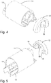
Fig. 4 shows a first exploded view of the housing part ofFig. 1 , -
Fig. 5 shows a second exploded view of the housing part ofFig. 1 , -
Fig. 6 shows an isometric view of a first mould cavity for the use in manufacturing the housing part offigs. 1 to 5 , -
Fig. 7 shows an isometric view of a core for the use in manufacturing the housing part offigs. 1 to 5 , -
Fig. 8 shows a cross-section along the line VIII-VIII offig. 6 with the core inserted, -
Fig. 9 shows a cross section along the line IX-IX offig. 7 with the core inserted, -
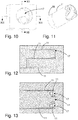
Fig. 10 shows an isometric view of a second mould cavity for the use in manufacturing the housing part offigs. 1 to 5 -
Fig. 11 shows the core ofFig. 7 with a first housing part attached, -
Fig. 12 shows a cross-section along the line XII-XII offig. 10 with the core inserted, -
Fig. 13 shows a cross section along the line XIII-XIII offig. 10 with the core inserted, and -
Fig. 14 shows an endoscope with a distal tip part in accordance with the invention. - Turning first to
Fig. 14 , anendoscope 1 exemplifying the vision device according to the invention is shown. Theendoscope 1 comprises ahandle 2 at the proximal end, aninsertion tube 3 extending towards the distal end where it comprises an articulatedbending section 4, which as the most distal segment has adistal tip part 5 according to the invention. Though omitted for illustration purposes the articulatedbending section 4 will normally be covered by a suitable sleeve, connected at least at its own distal end to thedistal tip part 5, e.g. by means of an adhesive. This as such is conventional and e.g. known from the aforementionedWO2014/106511 . Theendoscope 1 of the present invention is intended as a disposable endoscope to be thrown away after use and low manufacturing costs is therefore an important issue. - In
Fig. 2 thedistal tip part 5 can be seen in greater detail. Twotubular members proximal handle 2. The firsttubular member 6 provides a workingchannel 8 for theendoscope 1. The secondtubular member 7 serves as a conduit for electrical cables and/or optical fibres and/or illumination fibres, depending on which kind of illumination and imaging theendoscope 1 relies on. In the illustrated embodiment, the imaging and illumination relies on anelectronics section 9 with LEDs and a video camera accommodated in thedistal tip part 5, but the invention is not limited thereto. Rather, the present invention relates to thetip housing 10 rather than the details of what is accommodated therein. - In
Fig. 3 thetip housing 10 is shown on its own. As will be noticed from the different hatching as well as the exploded views ofFig. 4 and 5 , the tip housing comprises twodifferent materials second material 12 is a transparent material allowing light from the light source(s) such as LED(s) to pass and illuminate objects beyond the distal end of theendoscope 1. Accordingly, thesecond material 12 should have good optical properties, e.g. in terms of transparency and high index of refraction. However, not all materials render themselves for economically feasible manufacture and the use in environments for which the endoscope is intended. Thesecond material 12 is therefore preferably an injection mouldable polymer material such as polycarbonate, but other thermoplastic materials such as COP, COC and PMMA are also envisaged as are thermoset materials such as LSR (Liquid Silicone Rubber). One advantage of such softer and/or more elastic materials is their impact resistance. A softer and/or more elastic material would also allow for an increase in the transverse dimensions of the core 16 as the softer and/or more elastic material would yield during withdrawal thereof from themould cavity 17 in the moulding process described below. - The
first material 11 on the other hand need not have good optical properties and may therefore be selected based on entirely different criteria. - In particular the first material may be an opaque material. This will allow stray light from e.g. the light source to be absorbed and not disturb the images captured by the vision receptor, be it a video camera, an imaging chip, or an optical fibre. If opacity is the only desire, the
first material 11 may essentially be the same as thesecond material 12, i.e. the same plastic material with a filler or a dye to make it opaque. This ensures that the first and second materials are very compatible, allowing them to bond well together and ensure a water and airtight housing part 5. - Also, the
first material 11 may also be chosen for good adhesion properties to other materials, e.g. other parts of theendoscope 1. Such good adhesion properties could be good bonding to sealant materials, used for sealing the proximal end of the housing, e.g. around the lead-in 13 for electrical cables to theelectronics section 9, to prevent ingress of water and other pollutants that could potentially harm theelectronics section 9. Also, good bonding to an adhesive used for attaching the external sleeve around the bending section is advantageous. - Furthermore, the first material may be soft at least compared to the second material. In particular, it may be so soft that rather than attaching a sleeve to it, it may itself form a sleeve for the articulated
bending section 4 to which it is attached as the most distal segment. Furthermore, this would facilitate or enable demoulding of undercut features inside the housing because the material may deform elastically. - Evidently, there are numerous other design choices that come into play for the selection of the most suitable material for the
first material 11, provided of course that no further materials are used. The latter is, however, far from excluded by the present invention. Thus, if for the attachment of the tubular member 6 a number of spring likeprotrusions 14 are provided for holding the end of thetubular member 6, the material should be resilient enough to provide sufficient holding force, but of course with suitable adhesive properties, the tubular member could also be glued to the inside of theprotrusions 14 or a similar receptacle. - To achieve good tightness between the
first material 11 and thesecond material 12 they are according to the invention moulded together to form one integrated unit. A moulding process for this will be described below with reference toFigs. 6 to 13 . - Turning first to
Fig. 6 , an isometric view of a generally cylindricalfirst mould cavity 15 forming part of moulding tool for the use in the moulding process is shown, albeit only schematically as inlets and the like have been omitted. The moulding tool further comprises a core 16 adapted to be inserted into the first mould cavity to form a first configuration of the moulding tool as illustrated in the cross-sections ofFigs. 8 and 9 . Assuming that the first material is a thermoplastic material, then in this first configuration the hot liquefiedfirst material 11 is injected into themould cavity 15 under a suitable pressure. When the liquefiedfirst material 11 cools and solidifies it shrinks as most material do when they cool. Thus, when, after the cooling, thecore 16 is removed from thefirst mould cavity 15 the solidifiedfirst material 11 will stick to thecore 16 and be removed with it. This is in particular the case if additionalfirst material 11 is not injected under sustained pressure during the cooling stage.Fig. 11 shows the core 16 with thefirst material 11 stuck to it. If the first material is a thermoset material it will instead be injected in a cold state and subsequently heated to set or vulcanize the material. - The core 16 with the first material stuck to it is then used as a what is effectively a new core in a second generally
cylindrical mould cavity 17 forming as second configuration of the moulding tool, as can be seen in the cross-sections ofFigs. 12 and 13 . Here it will also be noted that in the preferred embodiment the volume of the resultingcavity 17 is smaller than the volume of thecavity 15. Accordingly, the volume of the second material introduced in the second moulding stage is smaller than the volume of the first material introduced in the first stage. Using a smaller volume results in a smaller part, in turn keeping the surface area with which it may adhere to the mould down. Filling the resultingcavity 15 at a higher pressure, and injecting additional second material as the second material cools, is therefore possible without the resulting housing sticking unnecessarily in the mould. The larger volume of the first material may be introduced at lower pressure ensuring that the shrinking material sticks to the core 16 rather than the mould, allowing for easy removal and reinsertion. - This remaining cavity can now be filled with the hot liquefied
second material 12 which fuses with thefirst material 11 when it solidifies and forms an integral unit as thehousing part 5. As described above in conjunction with the first material this may be a hot liquefied injection with subsequent cooling if the second material is a thermoplastic material or a cold injection with subsequent heating if the second material is a thermosetting material. Since this part formed from thesecond material 12 is located in front of the light source(s) and the vision receptor, be it a video camera, an imaging chip, or an optical fibre it is important to also ensure good optical properties of the finished part. Thus, thesecond material 12 is preferably injected under high pressure to ensure good filling of thecavity 17 without internal bubbles, and with sustained high pressure under the solidifying stage to avoid shrinking, which could deteriorate smoothness of the front surface and cause internal cavities. Furthermore, apart from the optical advantages gained form injecting the transparentsecond material 12 last, injecting this second material which will normally have a smaller volume is advantageous. This allows the above mentioned injection at higher pressures because the smaller volume decreases the risk of the shrinking material sticking to the core and/or moulds, even if additional material is injected to compensate for the shrinking. - After the
second material 12 has finished solidifying, thehousing part 5 comprising the bonded together first andsecond materials core 16 and may be removed from thesecond moulding cavity 17 with it, when the moulding tool is opened by retracting thecore 16. Thefinished housing part 5 may then be separated from the core 16 in a conventional manner by means of ejectors in the core 16 or in any other suitable manner, e.g. using a robot. - The moulding tool may preferably comprise two identical cores for one set of first and second cavities. With a suitable alternation arrangement, e.g. a revolver, one
core 16 may be used in the first moulding cavity while simultaneously theother core 16 with the solidifiedfirst material 11 thereon is used in the second moulding cavity and subsequently vice versa in an alternating manner. This arrangement may of course be multiplied with more sets of first and second cavities in sequence and a corresponding number of cores used in these cavities in one after the other. - The layout of the first and
second moulding cavities different housing part 5. Thus, either or both of first material andsecond material 12 could extend longer in the lengthwise direction i.e. from distal end towards proximal end. The layout of an opaque material could be shaped specifically to the output of the light sources. Likewise, the layout of the transparent material could be shaped specifically to the light sources. As best seen inFig. 5 this could involve the transparentsecond material 12 comprising integrated light guides 18, allowing the angular light distribution from LED light sources to be adapted to the field of view a video camera used as the image receptor. As can be seen the light guides in the present example are truncated pyramids with a generally rectangular cross-section which has been found useful for the rectangular image capture chip of a video camera. - Also, the
protective window 19 in front of the image receptor could comprise curved surfaces in order to act as a lens. - Furthermore, even though the description above has been given for sequential moulding it is not excluded that the housing part may be moulded in a co-injection process where the first and second housing materials are introduced e.g. simultaneously into a single moulding cavity through different inlets. This will allow control to be maintained over the location of the different materials without having to open, modify and reclose the mould, i.e. moving the
cores 16 with respect to themoulding cavities - With the housing part provided as an integral unit comprising two different materials it becomes possible to optimize the housing part for more than one parameter, e.g. for transparency vs. opacity, transparency vs. adhesion, brittleness vs. toughness, etc. The integral unit may be provided by other methods than the preferred one described above. In particular if injection moulding is used, an opposite arrangement could be used, i.e. a single moulding cavity, and two different cores inserted sequentially in that single moulding cavity, the first moulded part then remaining in the cavity when the second core is inserted. Analogous to the above, a number of identical cavities could then be used.
Claims (17)
- Method for manufacturing a tip housing for the distal tip of a vision device, such as an endoscope, said method comprising
providing a moulding tool,
introducing in the moulding tool a first housing material,
introducing in the moulding at least one further housing material different from the first housing material,
allowing the at least one further housing material to set and form a combined housing component with the first moulding material,
removing the combined housing component from the moulding tool. - Method according to claim 1, wherein the moulding tool comprises a first mould cavity, a second mould cavity and a core.
- Method according to any one of the preceding claims, wherein the first housing material is allowed to set before the at least one further housing material is introduced.
- Method according to any one of the preceding claims, wherein the volume of the at least one further housing material introduced in the mould is smaller than the volume of the first housing material introduced in the mould.
- Method according to any one of the preceding claims, wherein the at least one further housing material is selected from the group comprising thermoplastic materials, thermoset materials, and elastomers.
- Method according to any one of the preceding claims, wherein the at least one further housing material comprises a transparent housing material.
- Method according to any one of the preceding claims, wherein the first housing material is opaque.
- A method according to any one of the preceding claims wherein the set first material has better adhesion properties to glue than the set second material.
- Method according to any one of the preceding claims, wherein the first cavity and the second cavity have generally cylindrical shapes.
- Method according to any one of the preceding claims wherein the introduction of the first and/or the further housing material forms part of an injection moulding process.
- A tip housing for the distal tip of a vision device such as an endoscope obtained by the process according to any one of the preceding claims.
- A tip housing according to claim 11, wherein the at least one further housing material is a thermoplastic material.
- A tip housing according to claim 11 or 12, wherein the at least one further housing material comprises a transparent housing material.
- A tip housing according to any one of claims 11 to 13, wherein the first housing material is opaque.
- A tip housing according to any one of claims 11 to 14, wherein the set first material has better adhesion properties to glue than the set second material.
- A tip housing according to any one of claims 11 to 15, wherein the first cavity and the second cavity have generally cylindrical shapes.
- A vision device, such as an endoscope comprising a tip housing according to any one of claims 11 to 16.
Priority Applications (19)
| Application Number | Priority Date | Filing Date | Title |
|---|---|---|---|
| EP18161746.5A EP3539445A1 (en) | 2018-03-14 | 2018-03-14 | Method for manufacturing a tip housing |
| EP23198550.8A EP4273610A3 (en) | 2018-03-14 | 2019-03-11 | Method for manufacturing a pot-shaped tip housing |
| EP23205565.7A EP4286915B1 (en) | 2018-03-14 | 2019-03-11 | A tip part for an insertable vision device |
| EP21158346.3A EP3847949B1 (en) | 2018-03-14 | 2019-03-11 | A tip part for an insertable vision device |
| EP19161907.1A EP3539451B1 (en) | 2018-03-14 | 2019-03-11 | A tip part for an insertable vision device |
| EP19161898.2A EP3539450B1 (en) | 2018-03-14 | 2019-03-11 | A tip part for a vision device |
| EP19161893.3A EP3539449B1 (en) | 2018-03-14 | 2019-03-11 | Disposable insertion endoscope with a distal tip having a pot-shaped tip housing, and method for manufacturing the same |
| US16/351,632 US12053152B2 (en) | 2018-03-14 | 2019-03-13 | Tip part for a vision device |
| US16/352,437 US11291352B2 (en) | 2018-03-14 | 2019-03-13 | Method for manufacturing a tip housing |
| EP19709533.4A EP3764867A1 (en) | 2018-03-14 | 2019-03-14 | A tip part for an endoscope |
| CN201910194115.1A CN110269577B (en) | 2018-03-14 | 2019-03-14 | Method for manufacturing can-shaped tip shells |
| CN201980013807.XA CN111787841A (en) | 2018-03-14 | 2019-03-14 | tip for endoscope |
| US16/980,165 US11974723B2 (en) | 2018-03-14 | 2019-03-14 | Tip part for an endoscope |
| PCT/EP2019/056489 WO2019175350A1 (en) | 2018-03-14 | 2019-03-14 | A tip part for an endoscope |
| US17/149,686 US11779197B2 (en) | 2018-03-14 | 2021-01-14 | Tip part for a vision device |
| US17/579,294 US12185910B2 (en) | 2018-03-14 | 2022-01-19 | Method for manufacturing a tip housing |
| US18/616,999 US12245752B2 (en) | 2018-03-14 | 2024-03-26 | Tip part for an endoscope |
| US18/779,589 US20250049298A1 (en) | 2018-03-14 | 2024-07-22 | Tip Part For A Vision Device |
| US18/980,376 US20250107691A1 (en) | 2018-03-14 | 2024-12-13 | Method for manufacturing a tip housing |
Applications Claiming Priority (1)
| Application Number | Priority Date | Filing Date | Title |
|---|---|---|---|
| EP18161746.5A EP3539445A1 (en) | 2018-03-14 | 2018-03-14 | Method for manufacturing a tip housing |
Publications (1)
| Publication Number | Publication Date |
|---|---|
| EP3539445A1 true EP3539445A1 (en) | 2019-09-18 |
Family
ID=61655659
Family Applications (2)
| Application Number | Title | Priority Date | Filing Date |
|---|---|---|---|
| EP18161746.5A Withdrawn EP3539445A1 (en) | 2018-03-14 | 2018-03-14 | Method for manufacturing a tip housing |
| EP19709533.4A Pending EP3764867A1 (en) | 2018-03-14 | 2019-03-14 | A tip part for an endoscope |
Family Applications After (1)
| Application Number | Title | Priority Date | Filing Date |
|---|---|---|---|
| EP19709533.4A Pending EP3764867A1 (en) | 2018-03-14 | 2019-03-14 | A tip part for an endoscope |
Country Status (4)
| Country | Link |
|---|---|
| US (2) | US11974723B2 (en) |
| EP (2) | EP3539445A1 (en) |
| CN (2) | CN111787841A (en) |
| WO (1) | WO2019175350A1 (en) |
Cited By (2)
| Publication number | Priority date | Publication date | Assignee | Title |
|---|---|---|---|---|
| CN111685716A (en) * | 2020-07-24 | 2020-09-22 | 湖南省华芯医疗器械有限公司 | Endoscope front end assembly, endoscope and production mold |
| EP4104742A1 (en) * | 2021-06-15 | 2022-12-21 | Ambu A/S | An endoscope |
Families Citing this family (15)
| Publication number | Priority date | Publication date | Assignee | Title |
|---|---|---|---|---|
| EP3539445A1 (en) | 2018-03-14 | 2019-09-18 | Ambu A/S | Method for manufacturing a tip housing |
| EP3613327A1 (en) * | 2018-08-24 | 2020-02-26 | Ambu A/S | A tip part for a vision device |
| CN112313555B (en) * | 2018-12-05 | 2023-10-24 | Hoya株式会社 | Endoscope, front-end component and endoscope manufacturing method |
| EP3708061B1 (en) | 2019-03-14 | 2025-12-24 | Ambu A/S | A tip part for an endoscope |
| CN113349705B (en) * | 2020-03-04 | 2025-07-01 | 南微医学科技股份有限公司 | Imaging catheters, tips, tubing, and medical devices |
| EP4142565B1 (en) | 2020-04-27 | 2024-06-12 | Ambu A/S | An elongate articulated bending section body for an insertion endoscope |
| EP4056100A1 (en) | 2021-03-12 | 2022-09-14 | Ambu A/S | A tip part for a medical insertion vision device |
| CN113425227B (en) * | 2021-06-24 | 2022-09-06 | 哈尔滨工业大学 | Diagnosis-treatment integrated soft enterogastroscope medical robot |
| US12138399B2 (en) | 2021-10-28 | 2024-11-12 | Te Connectivity Solutions Gmbh | Sensor assembly with improved performance and connection |
| CN115067859B (en) * | 2022-06-20 | 2024-07-19 | 上海宇度医学科技股份有限公司 | Endoscope intubation assembly and endoscope |
| CN121568634A (en) * | 2023-08-07 | 2026-02-24 | 波士顿科学医学有限公司 | Electronic assembly for medical devices |
| EP4595862A1 (en) | 2024-01-30 | 2025-08-06 | Ambu A/S | Endoscope tip part with universal camera assembly |
| EP4595865A1 (en) | 2024-01-30 | 2025-08-06 | Ambu A/S | Endoscope tip part with universal camera assembly |
| EP4595863A1 (en) | 2024-01-30 | 2025-08-06 | Ambu A/S | Endoscope tip part with universal camera assembly |
| CN223464017U (en) * | 2024-10-30 | 2025-10-24 | 湖南省华芯医疗器械有限公司 | Front end seat, insertion part and endoscope |
Citations (11)
| Publication number | Priority date | Publication date | Assignee | Title |
|---|---|---|---|---|
| US5993378A (en) * | 1980-10-28 | 1999-11-30 | Lemelson; Jerome H. | Electro-optical instruments and methods for treating disease |
| US20040064018A1 (en) * | 2002-03-22 | 2004-04-01 | Robert Dunki-Jacobs | Integrated visualization system |
| JP3764512B2 (en) * | 1995-10-17 | 2006-04-12 | オリンパス株式会社 | Endoscopic optical components |
| WO2010066790A1 (en) | 2008-12-10 | 2010-06-17 | Ambu A/S | Endoscope having a camera housing and method for making a camera housing |
| US20120323078A1 (en) * | 2010-03-09 | 2012-12-20 | Olympus Medical Systems Corp. | Manufacturing method of resin molded article, resin molded article, resin molded article for endoscope, endoscope using resin molded article, and manufacturing apparatus of resin molded article |
| US20130175720A1 (en) * | 2010-09-02 | 2013-07-11 | Olympus Corporation | Resin molded product, method of manufacturing the same, die for resin molded product |
| US20140081085A1 (en) * | 2012-01-13 | 2014-03-20 | Olympus Medical Systems Corp. | Endoscope Tip Part and Endoscope |
| WO2014106511A1 (en) | 2013-01-07 | 2014-07-10 | Ambu A/S | An articulated tip part for an endoscope |
| US20160106306A1 (en) * | 2013-07-09 | 2016-04-21 | Olympus Corporation | Illumination device |
| US20170245734A1 (en) * | 2015-05-08 | 2017-08-31 | Olympus Corporation | Resin distal end component for endoscope |
| JP2018015250A (en) * | 2016-07-28 | 2018-02-01 | Hoya株式会社 | Endoscope illumination optical system and endoscope |
Family Cites Families (53)
| Publication number | Priority date | Publication date | Assignee | Title |
|---|---|---|---|---|
| US5609561A (en) * | 1992-06-09 | 1997-03-11 | Olympus Optical Co., Ltd | Electronic type endoscope in which image pickup unit is dismounted to execute disinfection/sterilization processing |
| EP0978251B1 (en) * | 1998-08-07 | 2005-01-26 | Olympus Corporation | Endoscope capable of being autoclaved |
| US7473218B2 (en) * | 2002-08-06 | 2009-01-06 | Olympus Corporation | Assembling method of capsule medical apparatus |
| JP4388288B2 (en) | 2003-02-19 | 2009-12-24 | オリンパス株式会社 | Endoscope |
| US20090185392A1 (en) * | 2003-03-26 | 2009-07-23 | Optim, Inc. | Detachable illumination system |
| US8435173B2 (en) | 2003-10-06 | 2013-05-07 | Olympus Corporation | Endoscope |
| US7785252B2 (en) * | 2004-11-23 | 2010-08-31 | Novare Surgical Systems, Inc. | Articulating sheath for flexible instruments |
| US8052597B2 (en) * | 2005-08-30 | 2011-11-08 | Boston Scientific Scimed, Inc. | Method for forming an endoscope articulation joint |
| US7955255B2 (en) * | 2006-04-20 | 2011-06-07 | Boston Scientific Scimed, Inc. | Imaging assembly with transparent distal cap |
| US7976459B2 (en) * | 2006-10-17 | 2011-07-12 | Intra L.L.C. | Portable endoscope for intubation |
| US8556807B2 (en) * | 2006-12-21 | 2013-10-15 | Intuitive Surgical Operations, Inc. | Hermetically sealed distal sensor endoscope |
| WO2010129324A2 (en) | 2009-05-08 | 2010-11-11 | Boston Scientific Scimed, Inc. | Endoscope with distal tip having encased optical components and display orientation capabilities |
| US9402533B2 (en) | 2011-03-07 | 2016-08-02 | Endochoice Innovation Center Ltd. | Endoscope circuit board assembly |
| US9642513B2 (en) * | 2009-06-18 | 2017-05-09 | Endochoice Inc. | Compact multi-viewing element endoscope system |
| US9713417B2 (en) * | 2009-06-18 | 2017-07-25 | Endochoice, Inc. | Image capture assembly for use in a multi-viewing elements endoscope |
| WO2012077116A1 (en) | 2010-12-09 | 2012-06-14 | Peermedical Ltd. | Flexible electronic circuit board for a multi-camera endoscope |
| KR101101658B1 (en) | 2009-11-16 | 2011-12-30 | 삼성전기주식회사 | Endoscopic camera module package and manufacturing method thereof |
| US9179831B2 (en) | 2009-11-30 | 2015-11-10 | King Systems Corporation | Visualization instrument |
| JP5189209B2 (en) * | 2010-02-01 | 2013-04-24 | オリンパスメディカルシステムズ株式会社 | Endoscope structure of endoscope |
| CN103228198B (en) * | 2010-09-08 | 2016-07-06 | 科维蒂恩有限合伙公司 | catheter with imaging assembly |
| EP2648602B1 (en) * | 2010-12-09 | 2018-07-18 | EndoChoice Innovation Center Ltd. | Flexible electronic circuit board multi-camera endoscope |
| EP2672878B1 (en) | 2011-02-07 | 2017-11-22 | Endochoice Innovation Center Ltd. | Multi-element cover for a multi-camera endoscope |
| JP5331840B2 (en) * | 2011-02-28 | 2013-10-30 | 富士フイルム株式会社 | Endoscope |
| PL2611356T3 (en) | 2011-07-11 | 2015-08-31 | Etview Ltd | Endobronchial tube |
| US9622649B2 (en) | 2011-08-05 | 2017-04-18 | Ambu A/S | Endoscope with a T-shaped flexible circuit board |
| EP2604175B1 (en) * | 2011-12-13 | 2019-11-20 | EndoChoice Innovation Center Ltd. | Removable tip endoscope |
| CN202408826U (en) * | 2012-01-26 | 2012-09-05 | 台州瀚创医疗器械科技有限公司 | Laryngoscope polarization type camera device |
| CN202821276U (en) * | 2012-08-22 | 2013-03-27 | 深圳市金科威实业有限公司 | Light source fixing device |
| US9198835B2 (en) * | 2012-09-07 | 2015-12-01 | Covidien Lp | Catheter with imaging assembly with placement aid and related methods therefor |
| EP3482673B1 (en) * | 2013-05-06 | 2020-09-16 | EndoChoice, Inc. | Image capture assembly for use in a multi-viewing elements endoscope |
| TWI583024B (en) | 2014-05-30 | 2017-05-11 | 榮晶生物科技股份有限公司 | Light-emitting diode package structure and camera module including the same |
| US10646107B2 (en) | 2015-05-27 | 2020-05-12 | Ambu A/S | Endoscope with a tool |
| US10898065B2 (en) * | 2015-06-16 | 2021-01-26 | Sharp Kabushiki Kaisha | In-vivo monitoring camera system |
| GB2555039A (en) | 2015-07-27 | 2018-04-18 | Halliburton Energy Services Inc | Methods and systems using an optical receiver and electro-optic methods to transmit data from integrated computational elements |
| US9913570B2 (en) * | 2015-08-07 | 2018-03-13 | Enlightenvue Llc | Endoscope with variable profile tip |
| US10478054B2 (en) | 2016-02-12 | 2019-11-19 | Ambu A/S | Endotracheal tube with visualization capabilities and a laryngeal mask |
| JP6617054B2 (en) * | 2016-03-03 | 2019-12-04 | 富士フイルム株式会社 | Endoscope |
| JP6326561B1 (en) * | 2016-06-27 | 2018-05-16 | オリンパス株式会社 | Endoscope, endoscope manufacturing method |
| EP3488204A4 (en) * | 2016-07-20 | 2020-07-22 | Verifood Ltd. | Accessories for handheld spectrometer |
| EP3756530B1 (en) | 2016-09-28 | 2023-01-11 | Ambu A/S | Endoscope adapted for facilitating bal procedures |
| WO2018131204A1 (en) | 2017-01-13 | 2018-07-19 | オリンパス株式会社 | Endoscope |
| WO2018150512A1 (en) * | 2017-02-16 | 2018-08-23 | オリンパス株式会社 | Optical module, endoscope, and method for manufacturing optical module |
| JP2018138111A (en) | 2017-02-24 | 2018-09-06 | オリンパス株式会社 | Led type tip optical adaptor |
| US20180344140A1 (en) * | 2017-05-30 | 2018-12-06 | Endochoice, Inc. | Illuminator window for a multiple viewing element endoscope |
| JP6860959B2 (en) | 2017-08-29 | 2021-04-21 | オリンパス株式会社 | How to replace the endoscope and the imaging device of the endoscope |
| WO2019094708A1 (en) * | 2017-11-09 | 2019-05-16 | Caldera Medical, Inc. | Rotary instruments and methods for intrauterine tissue resection |
| US12279748B2 (en) | 2018-02-14 | 2025-04-22 | Suzhou Acuvu Medical Technology Co. Ltd | Endoscopy system with off-center direction of view |
| EP4286915B1 (en) | 2018-03-14 | 2026-04-22 | Ambu A/S | A tip part for an insertable vision device |
| EP3539445A1 (en) | 2018-03-14 | 2019-09-18 | Ambu A/S | Method for manufacturing a tip housing |
| JP7026807B2 (en) | 2018-09-05 | 2022-02-28 | オリンパス株式会社 | The tip of the endoscope, the endoscope insertion part, and the endoscope |
| CN111315111B (en) | 2018-12-12 | 2023-05-23 | 荣晶生物科技股份有限公司 | Endoscope device, flexible circuit board assembly and flexible circuit board thereof |
| EP3708061B1 (en) | 2019-03-14 | 2025-12-24 | Ambu A/S | A tip part for an endoscope |
| EP4169431A1 (en) | 2021-10-25 | 2023-04-26 | Ambu A/S | An endoscope |
-
2018
- 2018-03-14 EP EP18161746.5A patent/EP3539445A1/en not_active Withdrawn
-
2019
- 2019-03-14 CN CN201980013807.XA patent/CN111787841A/en active Pending
- 2019-03-14 US US16/980,165 patent/US11974723B2/en active Active
- 2019-03-14 EP EP19709533.4A patent/EP3764867A1/en active Pending
- 2019-03-14 WO PCT/EP2019/056489 patent/WO2019175350A1/en not_active Ceased
- 2019-03-14 CN CN201910194115.1A patent/CN110269577B/en active Active
-
2024
- 2024-03-26 US US18/616,999 patent/US12245752B2/en active Active
Patent Citations (11)
| Publication number | Priority date | Publication date | Assignee | Title |
|---|---|---|---|---|
| US5993378A (en) * | 1980-10-28 | 1999-11-30 | Lemelson; Jerome H. | Electro-optical instruments and methods for treating disease |
| JP3764512B2 (en) * | 1995-10-17 | 2006-04-12 | オリンパス株式会社 | Endoscopic optical components |
| US20040064018A1 (en) * | 2002-03-22 | 2004-04-01 | Robert Dunki-Jacobs | Integrated visualization system |
| WO2010066790A1 (en) | 2008-12-10 | 2010-06-17 | Ambu A/S | Endoscope having a camera housing and method for making a camera housing |
| US20120323078A1 (en) * | 2010-03-09 | 2012-12-20 | Olympus Medical Systems Corp. | Manufacturing method of resin molded article, resin molded article, resin molded article for endoscope, endoscope using resin molded article, and manufacturing apparatus of resin molded article |
| US20130175720A1 (en) * | 2010-09-02 | 2013-07-11 | Olympus Corporation | Resin molded product, method of manufacturing the same, die for resin molded product |
| US20140081085A1 (en) * | 2012-01-13 | 2014-03-20 | Olympus Medical Systems Corp. | Endoscope Tip Part and Endoscope |
| WO2014106511A1 (en) | 2013-01-07 | 2014-07-10 | Ambu A/S | An articulated tip part for an endoscope |
| US20160106306A1 (en) * | 2013-07-09 | 2016-04-21 | Olympus Corporation | Illumination device |
| US20170245734A1 (en) * | 2015-05-08 | 2017-08-31 | Olympus Corporation | Resin distal end component for endoscope |
| JP2018015250A (en) * | 2016-07-28 | 2018-02-01 | Hoya株式会社 | Endoscope illumination optical system and endoscope |
Cited By (4)
| Publication number | Priority date | Publication date | Assignee | Title |
|---|---|---|---|---|
| CN111685716A (en) * | 2020-07-24 | 2020-09-22 | 湖南省华芯医疗器械有限公司 | Endoscope front end assembly, endoscope and production mold |
| CN111685716B (en) * | 2020-07-24 | 2022-03-22 | 湖南省华芯医疗器械有限公司 | Endoscope front end assembly, endoscope and production mold |
| EP4104742A1 (en) * | 2021-06-15 | 2022-12-21 | Ambu A/S | An endoscope |
| WO2022263506A1 (en) * | 2021-06-15 | 2022-12-22 | Ambu A/S | An endoscope |
Also Published As
| Publication number | Publication date |
|---|---|
| CN110269577B (en) | 2026-04-28 |
| US11974723B2 (en) | 2024-05-07 |
| EP3764867A1 (en) | 2021-01-20 |
| US20240225431A1 (en) | 2024-07-11 |
| WO2019175350A1 (en) | 2019-09-19 |
| CN111787841A (en) | 2020-10-16 |
| CN110269577A (en) | 2019-09-24 |
| US20200405137A1 (en) | 2020-12-31 |
| US12245752B2 (en) | 2025-03-11 |
Similar Documents
| Publication | Publication Date | Title |
|---|---|---|
| US12185910B2 (en) | Method for manufacturing a tip housing | |
| CN110269577B (en) | Method for manufacturing can-shaped tip shells | |
| US11794389B2 (en) | Tip part assembly for an endoscope | |
| US20230270319A1 (en) | Method for manufacture of a tip part and a tip part for an endoscope | |
| JP2024010148A5 (en) | ||
| EP3038510B1 (en) | Visualization instrument | |
| US20130175720A1 (en) | Resin molded product, method of manufacturing the same, die for resin molded product | |
| US20130006051A1 (en) | Video apparatus | |
| CN113905650A (en) | Housing for a disposable tip for insertion into an endoscope | |
| EP3628206B1 (en) | A method for manufacture of a tip part and a tip part for an endoscope | |
| CN109068948A (en) | Endoscope, method of manufacturing endoscope | |
| CN112545428A (en) | Tip segment for endoscope and manufacture thereof | |
| JP7459001B2 (en) | Distal end containing encapsulated components of the medical device | |
| CN110269582A (en) | For can be inserted into the point of sighting device | |
| EP3539446A1 (en) | A tip part for a vision device | |
| EP3788939B1 (en) | A tip part assembly for an endoscope and a method of manufacture of a tip part assembly of an endoscope | |
| JP4272903B2 (en) | Method for manufacturing transparent cap of endoscope with outer sheath | |
| US20260053336A1 (en) | Medical devices, systems, and methods | |
| JP2012024545A (en) | Covering body for preventing contamination of endoscopic device, and manufacturing method of the same | |
| CN114901118B (en) | Endoscope front end frame and endoscope |
Legal Events
| Date | Code | Title | Description |
|---|---|---|---|
| PUAI | Public reference made under article 153(3) epc to a published international application that has entered the european phase |
Free format text: ORIGINAL CODE: 0009012 |
|
| AK | Designated contracting states |
Kind code of ref document: A1 Designated state(s): AL AT BE BG CH CY CZ DE DK EE ES FI FR GB GR HR HU IE IS IT LI LT LU LV MC MK MT NL NO PL PT RO RS SE SI SK SM TR |
|
| AX | Request for extension of the european patent |
Extension state: BA ME |
|
| STAA | Information on the status of an ep patent application or granted ep patent |
Free format text: STATUS: THE APPLICATION IS DEEMED TO BE WITHDRAWN |
|
| 18D | Application deemed to be withdrawn |
Effective date: 20200603 |