EP3539367A1 - A tine device for an impeller apparatus - Google Patents
A tine device for an impeller apparatus Download PDFInfo
- Publication number
- EP3539367A1 EP3539367A1 EP19159987.7A EP19159987A EP3539367A1 EP 3539367 A1 EP3539367 A1 EP 3539367A1 EP 19159987 A EP19159987 A EP 19159987A EP 3539367 A1 EP3539367 A1 EP 3539367A1
- Authority
- EP
- European Patent Office
- Prior art keywords
- tine
- impeller apparatus
- rotor
- impeller
- bend angle
- Prior art date
- Legal status (The legal status is an assumption and is not a legal conclusion. Google has not performed a legal analysis and makes no representation as to the accuracy of the status listed.)
- Granted
Links
Images



Classifications
-
- A—HUMAN NECESSITIES
- A01—AGRICULTURE; FORESTRY; ANIMAL HUSBANDRY; HUNTING; TRAPPING; FISHING
- A01D—HARVESTING; MOWING
- A01D57/00—Delivering mechanisms for harvesters or mowers
- A01D57/28—Windrower attachments with tines
-
- A—HUMAN NECESSITIES
- A01—AGRICULTURE; FORESTRY; ANIMAL HUSBANDRY; HUNTING; TRAPPING; FISHING
- A01D—HARVESTING; MOWING
- A01D34/00—Mowers; Mowing apparatus of harvesters
- A01D34/01—Mowers; Mowing apparatus of harvesters characterised by features relating to the type of cutting apparatus
- A01D34/412—Mowers; Mowing apparatus of harvesters characterised by features relating to the type of cutting apparatus having rotating cutters
- A01D34/42—Mowers; Mowing apparatus of harvesters characterised by features relating to the type of cutting apparatus having rotating cutters having cutters rotating about a horizontal axis, e.g. cutting-cylinders
- A01D34/52—Cutting apparatus
- A01D34/535—Cutting apparatus with cutting members pivotally attached to the rotating axle, e.g. flails
-
- A—HUMAN NECESSITIES
- A01—AGRICULTURE; FORESTRY; ANIMAL HUSBANDRY; HUNTING; TRAPPING; FISHING
- A01D—HARVESTING; MOWING
- A01D82/00—Crop conditioners, i.e. machines for crushing or bruising stalks
Definitions
- the present disclosure relates generally to rotary impellers and, more particularly, to a tine device having a generally curved configuration that is designed for coupling to a rotor of an impeller apparatus.
- an impeller conditioner is provided with an impeller mounted for rotation about a horizontal transverse axis, and with a hood which extends arcuately, from front to rear, about the impeller.
- the impeller includes a rotor defined by a central cylindrical core to which a plurality of tines are pivotally attached at various locations along, and about, the circumference of the rotor. These tines are mounted so that, as viewed from an end of the rotor, they extend generally radially from the axis of rotation of the rotor when the impeller is being driven, with the tines then being subjected to centrifugal force.
- a tine device for an impeller apparatus comprises at least one tine element having a first end configured to be rotatably coupled to a central rotor of the impeller apparatus.
- the tine element additionally comprises a second end positioned on a first side of a radial line extending through the first end, and a curved portion located on an opposite second side of the radial line between the first and second ends.
- an impeller apparatus arranged in an agricultural mower-conditioner comprising a rotor, a plurality of coupling mechanisms arranged on the rotor; and a plurality of tine devices, in particular according to at least one of the claims 1 to 7.
- Each of the plurality of tine devices comprises at least one tine element having a first end configured to be rotatably coupled to the rotor via a respective coupling mechanism of the plurality of coupling mechanisms, a second end positioned on a first side of a radial line extending through the first end, and a curved portion located on an opposite second side of the radial line between the first and second ends.
- the at least one tine element comprises two or more tine elements arranged in opposed and mirrored relation relative to one another.
- each of the two or more tine elements is balanced about a radial centerline of the tine device.
- Embodiments of the present disclosure relates to a tine device having a generally curved configuration that is designed for coupling to a rotor of an impeller apparatus arranged in a mower-conditioner.
- a mower-conditioner header 100 is shown.
- the mower-conditioner header 100 includes a frame 102 supporting a housing 104 having opposite sides walls 105.
- a rotary cutter bar 108 extends transversely between the sides walls 105 and includes a plurality of rotary cutting units 110 mounted along the length of the cutter bar 108 in side-by-side relationship to each other.
- the converging drum 112 cooperates with the cutting units 110 to deliver cut crop to a discharge opening leading to an impeller housing 116 including opposite sides walls 113 and an arched rotor hood 114.
- Extending between, and mounted for rotation in, the sides walls 113 is an impeller 118 including a central rotor 120 defined by a cylindrical tube carrying a plurality of tine clips 122 (i.e., coupling mechanisms) to which a plurality of tine devices 130 are respectively pivotally mounted by pivot assemblies.
- the rotor hood 114 is spaced approximately concentric to a segment of the impeller 118 extending between ten and one o'clock positions of a circular path described by the outer periphery of the tine devices 130 during rotation of the impeller 118.
- a forming shield arrangement 140 Joined to and extending to the rear from the impeller housing 116 is a forming shield arrangement 140 including a horizontal top wall 142 and opposite, rearwardly converging side walls.
- a generally rectangular, vertical crop deflecting panel 146 having a forward edge hinged, as at 145 ( FIG. 2 ), for establishing a vertical pivot axis about which the deflecting panel 146 may be pivoted.
- the panels are disposed parallel to each other and inclined one way or the other relative to the vertical plane. Crop may be converged by the panels 146 by disposing the panels 146 so that they converge rearwardly.
- a rear panel 148 is mounted, as by transverse pins 150, to a rear end of the side wall 144 for pivoting vertically about a horizontal transverse axis defined by the pins 150.
- An arcuate fore-and-aft extending bracket 162 is provided at a central, rear location of the top wall 142 and contains a plurality of adjustment holes 164 for selectively receiving a coupling pin 166 for securing a connecting bracket 168 of the panel 148 to a desired adjustment hole 164 so that the rear panel is positioned in a desired position for deflecting crop toward the ground.
- a tine device 130 arranged for coupling to a rotor of an impeller apparatus is shown according to an embodiment.
- the tine device 130 can comprise at least two tine elements 230, 230a, 230b which are arranged in opposed parallel relation to one another (refer, e.g., to FIG. 3B ).
- each tine element 230, 230a, 230b can comprise a body member 235 having a first end portion 242 joined together with a second end portion 246 by an arcuate member 244.
- the body member 235 can comprise a generally high strength and rigid material such as, e.g., stainless steel.
- the second end portion 246 can comprise a generally tapered configuration that tapers outwardly from a lower end 247 to an upper end 249.
- at least one outer wall surface can comprise a generally curved configuration such as outer wall surface 250.
- the arcuate member 244 can comprise a first arcuate element 254 integrally formed with a second arcuate element 256.
- the first arcuate element 254 can be arranged to form a first bend angle 262 relative to a center axis 270 of the body member 235
- the second arcuate element 256 can be arranged to form a second bend angle 260 relative to the center axis 270 that is greater than the first bend angle 262.
- the angular orientations of the first and second arcuate elements 254, 256 relative to one another are such that the body member 235 has a first bend toward the positive lateral direction of the body member 235, and a second bend toward the opposite (negative lateral) direction of the body member 235.
- the relative arrangement of the first and second arcuate elements 254, 256 relative to one another causes at least a portion of the second end portion 246 to project outwardly and away from the center axis 270 of the body member 235.
- such features can be used to balance mass about the centerline of the tine device profile when the at least two tine elements 230, 230a, 230b are assembled together.
- the tine device 130 will have a center of mass lying on its vertical axis and thus, will not provide excessive fatigue to the pin due to side loading throughout its life and will still maintain its curved structure to allow for crop engagement off the back of the cutter bar (refer, e.g., to FIG. 1 ).
- the first end portion 242 can comprise at least one mounting aperture 243 that is sized to receive and accommodate one or more of the tine clips 122 arranged on the rotor 120.
- a lower end 241 of the second end portion 246 can comprise a generally pointed tip 245 having a recessed member 251 that is adapted for mating engaging with an outer of each tine clips 122.
- FIGS. 3A and 3B a plurality of fully assembled tine devices 130 mounted to the rotor 120 of the impeller apparatus are shown according to an embodiment.
- the tine elements 230, 230a, 230b are arranged in opposed relation to one another.
- the tine elements 230, 230a, 230b are positioned such that the first end portions 246 of each tine element 230, 230a, 230 face opposing directions.
- a generally v-shaped opening is formed between the lateral spacing areas of the first end portions 242.
- each of the second end portions 246 can also be arranged to face opposing directions and laterally spaced apart from one another by a predetermined distance.
- each of the plurality of tine devices 130 can be adjacently arranged in offset relation relative to one another such that each projects outwardly and away from an outer surface of the rotor 120.
- a technical effect of one or more of the example embodiments disclosed herein is a tine device for an impeller apparatus.
- the shape of the tine device is particularly advantageous and unique in that it provides an angle to incoming crop from a cutter bar and thus feeds better than a straight tine. Additionally, the tine device provides for a cost efficient solution to conventional approaches because it does not require expensive processes such as casting or welding in order to obtain its bend angle.
Landscapes
- Life Sciences & Earth Sciences (AREA)
- Environmental Sciences (AREA)
- Harvester Elements (AREA)
Abstract
Description
- The present disclosure relates generally to rotary impellers and, more particularly, to a tine device having a generally curved configuration that is designed for coupling to a rotor of an impeller apparatus.
- Typically, an impeller conditioner is provided with an impeller mounted for rotation about a horizontal transverse axis, and with a hood which extends arcuately, from front to rear, about the impeller. The impeller includes a rotor defined by a central cylindrical core to which a plurality of tines are pivotally attached at various locations along, and about, the circumference of the rotor. These tines are mounted so that, as viewed from an end of the rotor, they extend generally radially from the axis of rotation of the rotor when the impeller is being driven, with the tines then being subjected to centrifugal force. Additionally, when conditioning crop with an impeller of the type discussed above, some crop does not release correctly for being guided by the shields for forming the crop windrow, but rather is carried over where it is released directly to the ground. The carried over crop that is deposited outside of the normal bounds of a windrow that would normally be formed by the forming shields results in non-uniform looking windrows and causes the crop to dry at different rates. As such, to address the above concerns, there is a need in the art for an improved tine device.
- According to an aspect of the present disclosure, a tine device for an impeller apparatus is disclosed. The tine device comprises at least one tine element having a first end configured to be rotatably coupled to a central rotor of the impeller apparatus. The tine element additionally comprises a second end positioned on a first side of a radial line extending through the first end, and a curved portion located on an opposite second side of the radial line between the first and second ends.
- In another aspect, an impeller apparatus arranged in an agricultural mower-conditioner is disclosed. The device comprising a rotor, a plurality of coupling mechanisms arranged on the rotor; and a plurality of tine devices, in particular according to at least one of the claims 1 to 7. Each of the plurality of tine devices comprises at least one tine element having a first end configured to be rotatably coupled to the rotor via a respective coupling mechanism of the plurality of coupling mechanisms, a second end positioned on a first side of a radial line extending through the first end, and a curved portion located on an opposite second side of the radial line between the first and second ends. In an embodiment, the at least one tine element comprises two or more tine elements arranged in opposed and mirrored relation relative to one another. In another embodiment, each of the two or more tine elements is balanced about a radial centerline of the tine device.
- Other features and aspects will become apparent by consideration of the detailed description and accompanying drawings.
- The detailed description of the drawings refers to the accompanying figures in which:
-
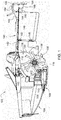
FIG. 1 is a right side cutaway view of a mower-conditioner header is shown according to an embodiment; -
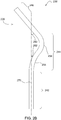
FIG. 2A is a side view of a tine element of a tine device according to an embodiment; -
FIG. 2B is a front view of the tine element ofFIG. 2A according to an embodiment; -
FIG. 2C is a front perspective view of the tine element ofFIG. 2A according to an embodiment; -
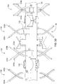
FIG. 3A is a front perspective view of a impeller apparatus arranged in the mower-conditioner header ofFIG. 1 according to an embodiment; and -
FIG. 3B is a side view of the impeller apparatus ofFIG. 3A according to an embodiment. - Embodiments of the present disclosure relates to a tine device having a generally curved configuration that is designed for coupling to a rotor of an impeller apparatus arranged in a mower-conditioner. Referring to
FIG. 1 , a mower-conditioner header 100 is shown. The mower-conditioner header 100 includes aframe 102 supporting ahousing 104 havingopposite sides walls 105. Arotary cutter bar 108 extends transversely between thesides walls 105 and includes a plurality ofrotary cutting units 110 mounted along the length of thecutter bar 108 in side-by-side relationship to each other. Located for rotation with outer end ones of thecutting units 110 is an outercrop converging drum 112. The convergingdrum 112 cooperates with thecutting units 110 to deliver cut crop to a discharge opening leading to animpeller housing 116 includingopposite sides walls 113 and anarched rotor hood 114. Extending between, and mounted for rotation in, thesides walls 113 is animpeller 118 including acentral rotor 120 defined by a cylindrical tube carrying a plurality of tine clips 122 (i.e., coupling mechanisms) to which a plurality oftine devices 130 are respectively pivotally mounted by pivot assemblies. Therotor hood 114 is spaced approximately concentric to a segment of theimpeller 118 extending between ten and one o'clock positions of a circular path described by the outer periphery of thetine devices 130 during rotation of theimpeller 118. - Joined to and extending to the rear from the
impeller housing 116 is a formingshield arrangement 140 including ahorizontal top wall 142 and opposite, rearwardly converging side walls. A generally rectangular, verticalcrop deflecting panel 146 having a forward edge hinged, as at 145 (FIG. 2 ), for establishing a vertical pivot axis about which thedeflecting panel 146 may be pivoted. - For deflecting crop to one side or the other of a vertical plane extending in the direction of operation of the mower-
conditioner header 100 and passing through a longitudinal center location of the mower-conditioner header 100, the panels are disposed parallel to each other and inclined one way or the other relative to the vertical plane. Crop may be converged by thepanels 146 by disposing thepanels 146 so that they converge rearwardly. Arear panel 148 is mounted, as bytransverse pins 150, to a rear end of theside wall 144 for pivoting vertically about a horizontal transverse axis defined by thepins 150. An arcuate fore-and-aft extending bracket 162 is provided at a central, rear location of thetop wall 142 and contains a plurality ofadjustment holes 164 for selectively receiving acoupling pin 166 for securing a connectingbracket 168 of thepanel 148 to a desiredadjustment hole 164 so that the rear panel is positioned in a desired position for deflecting crop toward the ground. - Referring to
FIGS. 2A-2C and3A-3B , atine device 130 arranged for coupling to a rotor of an impeller apparatus is shown according to an embodiment. In embodiments, thetine device 130 can comprise at least twotine elements FIG. 3B ). As depicted inFIGS. 2A-2C , eachtine element body member 235 having afirst end portion 242 joined together with asecond end portion 246 by anarcuate member 244. In various embodiments, thebody member 235 can comprise a generally high strength and rigid material such as, e.g., stainless steel. - The
second end portion 246 can comprise a generally tapered configuration that tapers outwardly from alower end 247 to anupper end 249. In some embodiments, at least one outer wall surface can comprise a generally curved configuration such asouter wall surface 250. - The
arcuate member 244 can comprise a firstarcuate element 254 integrally formed with a secondarcuate element 256. In some embodiments, the firstarcuate element 254 can be arranged to form afirst bend angle 262 relative to acenter axis 270 of thebody member 235, and the secondarcuate element 256 can be arranged to form asecond bend angle 260 relative to thecenter axis 270 that is greater than thefirst bend angle 262. - For example, the angular orientations of the first and second
arcuate elements body member 235 has a first bend toward the positive lateral direction of thebody member 235, and a second bend toward the opposite (negative lateral) direction of thebody member 235. Additionally, as depicted inFIGS. 2A and2B , the relative arrangement of the first and secondarcuate elements second end portion 246 to project outwardly and away from thecenter axis 270 of thebody member 235. Further, it should be noted that such features (i.e., the angular orientations/bend of the body member 235) can be used to balance mass about the centerline of the tine device profile when the at least twotine elements tine device 130 will have a center of mass lying on its vertical axis and thus, will not provide excessive fatigue to the pin due to side loading throughout its life and will still maintain its curved structure to allow for crop engagement off the back of the cutter bar (refer, e.g., toFIG. 1 ). - In some embodiments, the
first end portion 242 can comprise at least one mountingaperture 243 that is sized to receive and accommodate one or more of the tine clips 122 arranged on therotor 120. Alower end 241 of thesecond end portion 246 can comprise a generally pointedtip 245 having a recessedmember 251 that is adapted for mating engaging with an outer of each tine clips 122. - In
FIGS. 3A and3B , a plurality of fully assembledtine devices 130 mounted to therotor 120 of the impeller apparatus are shown according to an embodiment. As previously discussed thetine elements tine elements first end portions 246 of eachtine element first end portions 242. Similarly, each of thesecond end portions 246 can also be arranged to face opposing directions and laterally spaced apart from one another by a predetermined distance. Further, upon mounting to therotor 120, each of the plurality oftine devices 130 can be adjacently arranged in offset relation relative to one another such that each projects outwardly and away from an outer surface of therotor 120. - Without in any way limiting the scope, interpretation, or application of the claims appearing below, a technical effect of one or more of the example embodiments disclosed herein is a tine device for an impeller apparatus. The shape of the tine device is particularly advantageous and unique in that it provides an angle to incoming crop from a cutter bar and thus feeds better than a straight tine. Additionally, the tine device provides for a cost efficient solution to conventional approaches because it does not require expensive processes such as casting or welding in order to obtain its bend angle.
- While the above describes example embodiments of the present disclosure, these descriptions should not be viewed in a limiting sense. Rather, other variations and modifications may be made without departing from the scope and spirit of the present disclosure as defined in the appended claims.
Claims (15)
- A tine device for an impeller apparatus arranged in an agricultural mower-conditioner, the tine device (130) comprising: at least one tine element (230, 230a, 230b) having a first end configured to be rotatably coupled to a central rotor of the impeller apparatus, a second end positioned on a first side of a radial line extending through the first end, and a curved portion located on an opposite second side of the radial line between the first and second ends.
- The tine device of claim 1 further comprising at least one mounting aperture (243) formed in or on a portion of the first end, wherein the at least one mounting aperture (243) is sized to receive and accommodate one or more coupling mechanisms (122) arranged on the central rotor (120).
- The tine device of claim 1 or 2, wherein the curved portion comprises a first arcuate element (254) and a second arcuate element (256).
- The tine device according to at least one of the preceding claims, wherein the first arcuate element (254) and the second arcuate element (256) are arranged to respectively form a first bend angle (262) and a second bend angle (260), and wherein the second bend angle (260) is greater than the first bend angle (262).
- The tine device according to at least one of the preceding claims, wherein the second end is sized generally larger than the first end of the at least one tine element (230, 230a, 230b).
- The tine device according to at least one of the preceding claims, wherein the at least one tine device (130) comprises two or more tine elements (230, 230a, 230b) arranged in opposed and mirrored relation relative to one another.
- The tine device according to at least one of the preceding claims, wherein each of the two or more tine elements (230, 230a, 230b) is balanced about a radial centerline of the tine device (130).
- An impeller apparatus arranged in an agricultural mower-conditioner, the device comprising:a rotor (120);a plurality of coupling mechanisms (122) arranged on the rotor (120); anda plurality of tine devices (130), wherein each of the plurality of tine devices (130) comprises at least one tine element (230, 230a, 230b) having a first end configured to be rotatably coupled to the rotor (120) via a respective coupling mechanism (122) of the plurality of coupling mechanisms (122), a second end positioned on a first side of a radial line extending through the first end, and a curved portion located on an opposite second side of the radial line between the first and second ends.
- The impeller apparatus of claim 8, wherein the plurality of tine devices (130) project outwardly and away from an outer surface of the rotor (120).
- The impeller apparatus of claim 8 or 9, wherein each of the plurality of tine devices (130) is adjacently arranged in offset relation relative to one another.
- The impeller apparatus according to at least one of the claims 8 to 10, wherein the rotor (120) comprises a generally tubular configuration and is centrally arranged in the impeller apparatus.
- The impeller apparatus according to at least one of the claims 8 to 11further comprising at least one mounting aperture (243) formed in or on a portion of the first end, wherein the at least one mounting aperture (243) is sized to receive and accommodate one or more coupling mechanisms (122).
- The impeller apparatus according to at least one of the claims 8 to 12, wherein the curved portion comprises a first arcuate element (254) and a second arcuate element (256).
- The impeller apparatus according to at least one of the claims 8 to 13, wherein the first arcuate element (254) and the second arcuate element (256) are arranged to respectively form a first bend angle (262) and a second bend angle (260), and wherein the second bend angle (260) is greater than the first bend angle (262).
- The impeller apparatus according to at least one of the claims 8 to 14, wherein the second end is sized generally larger than the first end of the at least one tine element (230, 230a, 230b).
Applications Claiming Priority (1)
| Application Number | Priority Date | Filing Date | Title |
|---|---|---|---|
| US15/907,441 US10863674B2 (en) | 2018-02-28 | 2018-02-28 | Tine device for an impeller apparatus |
Publications (2)
| Publication Number | Publication Date |
|---|---|
| EP3539367A1 true EP3539367A1 (en) | 2019-09-18 |
| EP3539367B1 EP3539367B1 (en) | 2021-02-24 |
Family
ID=65635556
Family Applications (1)
| Application Number | Title | Priority Date | Filing Date |
|---|---|---|---|
| EP19159987.7A Active EP3539367B1 (en) | 2018-02-28 | 2019-02-28 | Mower-conditioner |
Country Status (2)
| Country | Link |
|---|---|
| US (1) | US10863674B2 (en) |
| EP (1) | EP3539367B1 (en) |
Families Citing this family (4)
| Publication number | Priority date | Publication date | Assignee | Title |
|---|---|---|---|---|
| US11259465B2 (en) * | 2016-10-28 | 2022-03-01 | Deere & Company | Impeller with auger for an agricultural machine |
| USD911397S1 (en) * | 2018-02-28 | 2021-02-23 | Deere & Company | Tine device |
| US11439068B2 (en) | 2019-02-08 | 2022-09-13 | Deere & Company | Impeller conditioner including a tine device with limited lateral movement |
| US11096329B2 (en) * | 2019-05-31 | 2021-08-24 | Deere & Company | Crop conditioner hood with integrated swathboard |
Citations (6)
| Publication number | Priority date | Publication date | Assignee | Title |
|---|---|---|---|---|
| GB816422A (en) * | 1955-04-16 | 1959-07-15 | Wilder Ltd John | Improvements in or relating to appliances for cutting and lifting from the ground growing crops and for lifting from the ground crops already cut |
| DE1209790B (en) * | 1964-04-24 | 1966-01-27 | Massey Ferguson Inc | Rotor for forage harvesting machines |
| NL6601022A (en) * | 1966-01-27 | 1967-07-28 | ||
| FR2776953A1 (en) * | 1998-04-07 | 1999-10-08 | Edouard Boisson | Semi-rigid rotary grass cutter |
| US20060213172A1 (en) * | 2005-03-26 | 2006-09-28 | David Beaufort | Tine of a conditioner roller |
| EP1723843A1 (en) * | 2005-05-19 | 2006-11-22 | ESM ENNEPETALER SCHNEID- UND MÄHTECHNIK GMBH & CO. KG | Apparatus for cutting and mulching of in particular high grown grass cuttings |
Family Cites Families (32)
| Publication number | Priority date | Publication date | Assignee | Title |
|---|---|---|---|---|
| US2841946A (en) * | 1955-01-07 | 1958-07-08 | Deere Mfg Co | Forage harvester knives |
| US3027702A (en) * | 1958-08-01 | 1962-04-03 | Phares & Wilkins Mfg Co | Stalk shredder |
| US2990667A (en) * | 1959-08-11 | 1961-07-04 | Sperry Rand Corp | Forage harvester |
| US3147577A (en) * | 1962-12-14 | 1964-09-08 | Deere & Co | Crop handling machine |
| US3222854A (en) * | 1964-03-02 | 1965-12-14 | Jacobsen Mfg Co | Swing-knife mounting |
| DE1215999B (en) * | 1964-09-28 | 1966-05-05 | Int Harvester Co | Holding device for the flails of a Schlegelmaehhaeckslers |
| US3335555A (en) * | 1964-12-02 | 1967-08-15 | Int Harvester Co | Flail knife structure |
| US3411279A (en) * | 1965-07-21 | 1968-11-19 | Int Harvester Co | Flail knife assembly |
| US3465507A (en) * | 1967-02-23 | 1969-09-09 | Jacobsen Mfg Co | Flail knife assembly |
| US3505800A (en) * | 1967-05-04 | 1970-04-14 | Hesston Of Delaware Inc | Cutter assembly for a flail-type mower |
| US3527038A (en) * | 1968-08-26 | 1970-09-08 | Hesston Of Delaware Inc | Quick-change flail blade |
| BE755086A (en) * | 1969-09-08 | 1971-02-01 | Mott Corp | BALANCED ROTOR FOR LAWN MOWERS AND SIMILAR MOWERS |
| US3604188A (en) * | 1969-10-31 | 1971-09-14 | Mott Corp | Cutting blade attachment for a mower |
| US3657869A (en) * | 1969-12-01 | 1972-04-25 | Anthes Imperial Ltd | Flail |
| US3678668A (en) * | 1970-09-25 | 1972-07-25 | Mott Corp | Mower blade and connection therefor |
| US3678671A (en) * | 1971-02-26 | 1972-07-25 | Int Harvester Co | Flail shredder |
| US3754384A (en) * | 1971-07-12 | 1973-08-28 | Hesston Corp | Mowing, conditioning and windrowing machine |
| US3977165A (en) * | 1971-12-08 | 1976-08-31 | National Research Development Corporation | Conditioning crops |
| US3693335A (en) * | 1972-01-03 | 1972-09-26 | Mathews B C | Flail type rotor assembly and blade for same |
| US4021995A (en) * | 1975-11-10 | 1977-05-10 | Hesston Corporation | Crop conditioning rotor |
| US4182099A (en) * | 1977-11-21 | 1980-01-08 | Deere & Company | Impeller mower-conditioner rotor |
| US4211060A (en) * | 1978-08-21 | 1980-07-08 | Hesston Corporation | Mowing rotor |
| DE3726522A1 (en) | 1987-08-10 | 1989-02-23 | Standard Elektrik Lorenz Ag | FAN WHEEL MADE FROM A METAL SHEET AND METHOD FOR THE PRODUCTION THEREOF |
| US4905460A (en) * | 1988-06-20 | 1990-03-06 | Cushman, Inc. | Mulching bar for a core processor or power rake |
| CA2066431A1 (en) * | 1989-09-18 | 1991-03-19 | Erling Roynberg | Rotary agricultural tool |
| JP2855089B2 (en) * | 1995-06-07 | 1999-02-10 | 政則 西岡 | Trailed mower |
| US6640605B2 (en) | 1999-01-27 | 2003-11-04 | Milgo Industrial, Inc. | Method of bending sheet metal to form three-dimensional structures |
| US6478674B2 (en) * | 1999-11-24 | 2002-11-12 | Leo Redekop | Apparatus including twisted blades passing between stationary blades for chopping and discharging straw from a combine harvester |
| US6511374B2 (en) * | 2001-02-02 | 2003-01-28 | Case Corporation | Hub and blade assembly for an agricultural combine residue handling system |
| FR2838602B1 (en) * | 2002-04-18 | 2004-09-03 | Kuhn Sa | FORAGE TREATMENT DEVICE AND AGRICULTURAL MOWER USING SUCH A FORAGE TREATMENT DEVICE |
| US6692351B2 (en) * | 2002-07-17 | 2004-02-17 | Case Corporation | Crop residue chopper with reconfigurable fixed offset blades |
| US8166740B2 (en) | 2005-02-21 | 2012-05-01 | Deere & Company | Impeller conditioner rotor equipped with curved tines |
-
2018
- 2018-02-28 US US15/907,441 patent/US10863674B2/en active Active
-
2019
- 2019-02-28 EP EP19159987.7A patent/EP3539367B1/en active Active
Patent Citations (6)
| Publication number | Priority date | Publication date | Assignee | Title |
|---|---|---|---|---|
| GB816422A (en) * | 1955-04-16 | 1959-07-15 | Wilder Ltd John | Improvements in or relating to appliances for cutting and lifting from the ground growing crops and for lifting from the ground crops already cut |
| DE1209790B (en) * | 1964-04-24 | 1966-01-27 | Massey Ferguson Inc | Rotor for forage harvesting machines |
| NL6601022A (en) * | 1966-01-27 | 1967-07-28 | ||
| FR2776953A1 (en) * | 1998-04-07 | 1999-10-08 | Edouard Boisson | Semi-rigid rotary grass cutter |
| US20060213172A1 (en) * | 2005-03-26 | 2006-09-28 | David Beaufort | Tine of a conditioner roller |
| EP1723843A1 (en) * | 2005-05-19 | 2006-11-22 | ESM ENNEPETALER SCHNEID- UND MÄHTECHNIK GMBH & CO. KG | Apparatus for cutting and mulching of in particular high grown grass cuttings |
Also Published As
| Publication number | Publication date |
|---|---|
| US20190261567A1 (en) | 2019-08-29 |
| US10863674B2 (en) | 2020-12-15 |
| EP3539367B1 (en) | 2021-02-24 |
Similar Documents
| Publication | Publication Date | Title |
|---|---|---|
| EP3539367B1 (en) | Mower-conditioner | |
| US5482508A (en) | Apparatus for chopping and discharging straw from a combine harvester | |
| US5042973A (en) | Straw cutter | |
| US20020004417A1 (en) | Apparatus for chopping and discharging straw from a combine harvester | |
| US8833048B2 (en) | Harvesting header bat with adjustably spaced quick release fingers | |
| US5919087A (en) | Concave latch mechanism for an agricultural combine | |
| US6343986B1 (en) | Combine straw and chaff spreader | |
| US4444000A (en) | Harvester header construction | |
| US6453654B1 (en) | Apparatus for conditioning crop materials | |
| US8166740B2 (en) | Impeller conditioner rotor equipped with curved tines | |
| US3546863A (en) | Pick-up reel for harvesting machinery | |
| EP3669636B1 (en) | A split reel combine header | |
| BR112020018484B1 (en) | AGRICULTURAL COMBINED HARVESTER | |
| EP3695704B1 (en) | An impeller conditioner including a tine device with limited lateral movement | |
| CN215122230U (en) | Width-adjustable divider and harvester | |
| US5129216A (en) | Crop blower | |
| CN216650545U (en) | Harvester divider and harvester | |
| KR102667806B1 (en) | Detachable one-stop harvesting automation equipment | |
| US20120210691A1 (en) | Bell Knife for Rotary Mower | |
| EP0841001B1 (en) | Concave latch mechanism for an agricultural combine | |
| CA2406531C (en) | Axial flow combine and impeller for rotor thereof | |
| EP0336513A1 (en) | An agricultural machine comprising a tine loss protection means | |
| EP4032391B1 (en) | Mower conditioner impeller hood actuating mechanism | |
| CN215601998U (en) | Silage harvester folding header guide rod assembly and silage harvester folding header | |
| JPH01257410A (en) | Whole culm charging combine |
Legal Events
| Date | Code | Title | Description |
|---|---|---|---|
| PUAI | Public reference made under article 153(3) epc to a published international application that has entered the european phase |
Free format text: ORIGINAL CODE: 0009012 |
|
| STAA | Information on the status of an ep patent application or granted ep patent |
Free format text: STATUS: THE APPLICATION HAS BEEN PUBLISHED |
|
| AK | Designated contracting states |
Kind code of ref document: A1 Designated state(s): AL AT BE BG CH CY CZ DE DK EE ES FI FR GB GR HR HU IE IS IT LI LT LU LV MC MK MT NL NO PL PT RO RS SE SI SK SM TR |
|
| AX | Request for extension of the european patent |
Extension state: BA ME |
|
| STAA | Information on the status of an ep patent application or granted ep patent |
Free format text: STATUS: REQUEST FOR EXAMINATION WAS MADE |
|
| 17P | Request for examination filed |
Effective date: 20200318 |
|
| RBV | Designated contracting states (corrected) |
Designated state(s): AL AT BE BG CH CY CZ DE DK EE ES FI FR GB GR HR HU IE IS IT LI LT LU LV MC MK MT NL NO PL PT RO RS SE SI SK SM TR |
|
| GRAP | Despatch of communication of intention to grant a patent |
Free format text: ORIGINAL CODE: EPIDOSNIGR1 |
|
| STAA | Information on the status of an ep patent application or granted ep patent |
Free format text: STATUS: GRANT OF PATENT IS INTENDED |
|
| RIC1 | Information provided on ipc code assigned before grant |
Ipc: A01D 34/535 20060101AFI20200917BHEP Ipc: A01D 82/00 20060101ALI20200917BHEP |
|
| INTG | Intention to grant announced |
Effective date: 20201014 |
|
| GRAS | Grant fee paid |
Free format text: ORIGINAL CODE: EPIDOSNIGR3 |
|
| GRAA | (expected) grant |
Free format text: ORIGINAL CODE: 0009210 |
|
| STAA | Information on the status of an ep patent application or granted ep patent |
Free format text: STATUS: THE PATENT HAS BEEN GRANTED |
|
| AK | Designated contracting states |
Kind code of ref document: B1 Designated state(s): AL AT BE BG CH CY CZ DE DK EE ES FI FR GB GR HR HU IE IS IT LI LT LU LV MC MK MT NL NO PL PT RO RS SE SI SK SM TR |
|
| REG | Reference to a national code |
Ref country code: CH Ref legal event code: EP |
|
| REG | Reference to a national code |
Ref country code: AT Ref legal event code: REF Ref document number: 1363294 Country of ref document: AT Kind code of ref document: T Effective date: 20210315 |
|
| REG | Reference to a national code |
Ref country code: IE Ref legal event code: FG4D |
|
| REG | Reference to a national code |
Ref country code: DE Ref legal event code: R096 Ref document number: 602019002645 Country of ref document: DE |
|
| REG | Reference to a national code |
Ref country code: LT Ref legal event code: MG9D |
|
| REG | Reference to a national code |
Ref country code: NL Ref legal event code: MP Effective date: 20210224 |
|
| PG25 | Lapsed in a contracting state [announced via postgrant information from national office to epo] |
Ref country code: BG Free format text: LAPSE BECAUSE OF FAILURE TO SUBMIT A TRANSLATION OF THE DESCRIPTION OR TO PAY THE FEE WITHIN THE PRESCRIBED TIME-LIMIT Effective date: 20210524 Ref country code: FI Free format text: LAPSE BECAUSE OF FAILURE TO SUBMIT A TRANSLATION OF THE DESCRIPTION OR TO PAY THE FEE WITHIN THE PRESCRIBED TIME-LIMIT Effective date: 20210224 Ref country code: HR Free format text: LAPSE BECAUSE OF FAILURE TO SUBMIT A TRANSLATION OF THE DESCRIPTION OR TO PAY THE FEE WITHIN THE PRESCRIBED TIME-LIMIT Effective date: 20210224 Ref country code: GR Free format text: LAPSE BECAUSE OF FAILURE TO SUBMIT A TRANSLATION OF THE DESCRIPTION OR TO PAY THE FEE WITHIN THE PRESCRIBED TIME-LIMIT Effective date: 20210525 Ref country code: NO Free format text: LAPSE BECAUSE OF FAILURE TO SUBMIT A TRANSLATION OF THE DESCRIPTION OR TO PAY THE FEE WITHIN THE PRESCRIBED TIME-LIMIT Effective date: 20210524 Ref country code: PT Free format text: LAPSE BECAUSE OF FAILURE TO SUBMIT A TRANSLATION OF THE DESCRIPTION OR TO PAY THE FEE WITHIN THE PRESCRIBED TIME-LIMIT Effective date: 20210624 Ref country code: LT Free format text: LAPSE BECAUSE OF FAILURE TO SUBMIT A TRANSLATION OF THE DESCRIPTION OR TO PAY THE FEE WITHIN THE PRESCRIBED TIME-LIMIT Effective date: 20210224 |
|
| REG | Reference to a national code |
Ref country code: AT Ref legal event code: MK05 Ref document number: 1363294 Country of ref document: AT Kind code of ref document: T Effective date: 20210224 |
|
| PG25 | Lapsed in a contracting state [announced via postgrant information from national office to epo] |
Ref country code: RS Free format text: LAPSE BECAUSE OF FAILURE TO SUBMIT A TRANSLATION OF THE DESCRIPTION OR TO PAY THE FEE WITHIN THE PRESCRIBED TIME-LIMIT Effective date: 20210224 Ref country code: PL Free format text: LAPSE BECAUSE OF FAILURE TO SUBMIT A TRANSLATION OF THE DESCRIPTION OR TO PAY THE FEE WITHIN THE PRESCRIBED TIME-LIMIT Effective date: 20210224 Ref country code: NL Free format text: LAPSE BECAUSE OF FAILURE TO SUBMIT A TRANSLATION OF THE DESCRIPTION OR TO PAY THE FEE WITHIN THE PRESCRIBED TIME-LIMIT Effective date: 20210224 Ref country code: LV Free format text: LAPSE BECAUSE OF FAILURE TO SUBMIT A TRANSLATION OF THE DESCRIPTION OR TO PAY THE FEE WITHIN THE PRESCRIBED TIME-LIMIT Effective date: 20210224 Ref country code: SE Free format text: LAPSE BECAUSE OF FAILURE TO SUBMIT A TRANSLATION OF THE DESCRIPTION OR TO PAY THE FEE WITHIN THE PRESCRIBED TIME-LIMIT Effective date: 20210224 |
|
| PG25 | Lapsed in a contracting state [announced via postgrant information from national office to epo] |
Ref country code: IS Free format text: LAPSE BECAUSE OF FAILURE TO SUBMIT A TRANSLATION OF THE DESCRIPTION OR TO PAY THE FEE WITHIN THE PRESCRIBED TIME-LIMIT Effective date: 20210624 |
|
| REG | Reference to a national code |
Ref country code: BE Ref legal event code: MM Effective date: 20210228 |
|
| PG25 | Lapsed in a contracting state [announced via postgrant information from national office to epo] |
Ref country code: LU Free format text: LAPSE BECAUSE OF NON-PAYMENT OF DUE FEES Effective date: 20210228 Ref country code: CZ Free format text: LAPSE BECAUSE OF FAILURE TO SUBMIT A TRANSLATION OF THE DESCRIPTION OR TO PAY THE FEE WITHIN THE PRESCRIBED TIME-LIMIT Effective date: 20210224 Ref country code: EE Free format text: LAPSE BECAUSE OF FAILURE TO SUBMIT A TRANSLATION OF THE DESCRIPTION OR TO PAY THE FEE WITHIN THE PRESCRIBED TIME-LIMIT Effective date: 20210224 Ref country code: AT Free format text: LAPSE BECAUSE OF FAILURE TO SUBMIT A TRANSLATION OF THE DESCRIPTION OR TO PAY THE FEE WITHIN THE PRESCRIBED TIME-LIMIT Effective date: 20210224 Ref country code: SM Free format text: LAPSE BECAUSE OF FAILURE TO SUBMIT A TRANSLATION OF THE DESCRIPTION OR TO PAY THE FEE WITHIN THE PRESCRIBED TIME-LIMIT Effective date: 20210224 |
|
| REG | Reference to a national code |
Ref country code: DE Ref legal event code: R097 Ref document number: 602019002645 Country of ref document: DE |
|
| PG25 | Lapsed in a contracting state [announced via postgrant information from national office to epo] |
Ref country code: MC Free format text: LAPSE BECAUSE OF FAILURE TO SUBMIT A TRANSLATION OF THE DESCRIPTION OR TO PAY THE FEE WITHIN THE PRESCRIBED TIME-LIMIT Effective date: 20210224 Ref country code: DK Free format text: LAPSE BECAUSE OF FAILURE TO SUBMIT A TRANSLATION OF THE DESCRIPTION OR TO PAY THE FEE WITHIN THE PRESCRIBED TIME-LIMIT Effective date: 20210224 Ref country code: SK Free format text: LAPSE BECAUSE OF FAILURE TO SUBMIT A TRANSLATION OF THE DESCRIPTION OR TO PAY THE FEE WITHIN THE PRESCRIBED TIME-LIMIT Effective date: 20210224 Ref country code: RO Free format text: LAPSE BECAUSE OF FAILURE TO SUBMIT A TRANSLATION OF THE DESCRIPTION OR TO PAY THE FEE WITHIN THE PRESCRIBED TIME-LIMIT Effective date: 20210224 |
|
| PLBE | No opposition filed within time limit |
Free format text: ORIGINAL CODE: 0009261 |
|
| STAA | Information on the status of an ep patent application or granted ep patent |
Free format text: STATUS: NO OPPOSITION FILED WITHIN TIME LIMIT |
|
| PG25 | Lapsed in a contracting state [announced via postgrant information from national office to epo] |
Ref country code: AL Free format text: LAPSE BECAUSE OF FAILURE TO SUBMIT A TRANSLATION OF THE DESCRIPTION OR TO PAY THE FEE WITHIN THE PRESCRIBED TIME-LIMIT Effective date: 20210224 Ref country code: IE Free format text: LAPSE BECAUSE OF NON-PAYMENT OF DUE FEES Effective date: 20210228 Ref country code: ES Free format text: LAPSE BECAUSE OF FAILURE TO SUBMIT A TRANSLATION OF THE DESCRIPTION OR TO PAY THE FEE WITHIN THE PRESCRIBED TIME-LIMIT Effective date: 20210224 |
|
| 26N | No opposition filed |
Effective date: 20211125 |
|
| PG25 | Lapsed in a contracting state [announced via postgrant information from national office to epo] |
Ref country code: SI Free format text: LAPSE BECAUSE OF FAILURE TO SUBMIT A TRANSLATION OF THE DESCRIPTION OR TO PAY THE FEE WITHIN THE PRESCRIBED TIME-LIMIT Effective date: 20210224 |
|
| PG25 | Lapsed in a contracting state [announced via postgrant information from national office to epo] |
Ref country code: IT Free format text: LAPSE BECAUSE OF FAILURE TO SUBMIT A TRANSLATION OF THE DESCRIPTION OR TO PAY THE FEE WITHIN THE PRESCRIBED TIME-LIMIT Effective date: 20210224 |
|
| PG25 | Lapsed in a contracting state [announced via postgrant information from national office to epo] |
Ref country code: IS Free format text: LAPSE BECAUSE OF FAILURE TO SUBMIT A TRANSLATION OF THE DESCRIPTION OR TO PAY THE FEE WITHIN THE PRESCRIBED TIME-LIMIT Effective date: 20210624 |
|
| PG25 | Lapsed in a contracting state [announced via postgrant information from national office to epo] |
Ref country code: BE Free format text: LAPSE BECAUSE OF NON-PAYMENT OF DUE FEES Effective date: 20210228 |
|
| REG | Reference to a national code |
Ref country code: CH Ref legal event code: PL |
|
| PG25 | Lapsed in a contracting state [announced via postgrant information from national office to epo] |
Ref country code: LI Free format text: LAPSE BECAUSE OF NON-PAYMENT OF DUE FEES Effective date: 20220228 Ref country code: CH Free format text: LAPSE BECAUSE OF NON-PAYMENT OF DUE FEES Effective date: 20220228 |
|
| PG25 | Lapsed in a contracting state [announced via postgrant information from national office to epo] |
Ref country code: CY Free format text: LAPSE BECAUSE OF FAILURE TO SUBMIT A TRANSLATION OF THE DESCRIPTION OR TO PAY THE FEE WITHIN THE PRESCRIBED TIME-LIMIT Effective date: 20210224 |
|
| PG25 | Lapsed in a contracting state [announced via postgrant information from national office to epo] |
Ref country code: HU Free format text: LAPSE BECAUSE OF FAILURE TO SUBMIT A TRANSLATION OF THE DESCRIPTION OR TO PAY THE FEE WITHIN THE PRESCRIBED TIME-LIMIT; INVALID AB INITIO Effective date: 20190228 |
|
| GBPC | Gb: european patent ceased through non-payment of renewal fee |
Effective date: 20230228 |
|
| PG25 | Lapsed in a contracting state [announced via postgrant information from national office to epo] |
Ref country code: GB Free format text: LAPSE BECAUSE OF NON-PAYMENT OF DUE FEES Effective date: 20230228 |
|
| PG25 | Lapsed in a contracting state [announced via postgrant information from national office to epo] |
Ref country code: GB Free format text: LAPSE BECAUSE OF NON-PAYMENT OF DUE FEES Effective date: 20230228 |
|
| PG25 | Lapsed in a contracting state [announced via postgrant information from national office to epo] |
Ref country code: MK Free format text: LAPSE BECAUSE OF FAILURE TO SUBMIT A TRANSLATION OF THE DESCRIPTION OR TO PAY THE FEE WITHIN THE PRESCRIBED TIME-LIMIT Effective date: 20210224 |
|
| PG25 | Lapsed in a contracting state [announced via postgrant information from national office to epo] |
Ref country code: TR Free format text: LAPSE BECAUSE OF FAILURE TO SUBMIT A TRANSLATION OF THE DESCRIPTION OR TO PAY THE FEE WITHIN THE PRESCRIBED TIME-LIMIT Effective date: 20210224 |
|
| PG25 | Lapsed in a contracting state [announced via postgrant information from national office to epo] |
Ref country code: MT Free format text: LAPSE BECAUSE OF FAILURE TO SUBMIT A TRANSLATION OF THE DESCRIPTION OR TO PAY THE FEE WITHIN THE PRESCRIBED TIME-LIMIT Effective date: 20210224 |
|
| PGFP | Annual fee paid to national office [announced via postgrant information from national office to epo] |
Ref country code: DE Payment date: 20260121 Year of fee payment: 8 |
|
| PGFP | Annual fee paid to national office [announced via postgrant information from national office to epo] |
Ref country code: FR Payment date: 20260225 Year of fee payment: 8 |