EP3538805B1 - Threaded fastener assembly with concealed threads - Google Patents
Threaded fastener assembly with concealed threads Download PDFInfo
- Publication number
- EP3538805B1 EP3538805B1 EP17808653.4A EP17808653A EP3538805B1 EP 3538805 B1 EP3538805 B1 EP 3538805B1 EP 17808653 A EP17808653 A EP 17808653A EP 3538805 B1 EP3538805 B1 EP 3538805B1
- Authority
- EP
- European Patent Office
- Prior art keywords
- nut
- threaded
- bore
- bolt
- diameter
- Prior art date
- Legal status (The legal status is an assumption and is not a legal conclusion. Google has not performed a legal analysis and makes no representation as to the accuracy of the status listed.)
- Active
Links
Images


Classifications
-
- F—MECHANICAL ENGINEERING; LIGHTING; HEATING; WEAPONS; BLASTING
- F16—ENGINEERING ELEMENTS AND UNITS; GENERAL MEASURES FOR PRODUCING AND MAINTAINING EFFECTIVE FUNCTIONING OF MACHINES OR INSTALLATIONS; THERMAL INSULATION IN GENERAL
- F16L—PIPES; JOINTS OR FITTINGS FOR PIPES; SUPPORTS FOR PIPES, CABLES OR PROTECTIVE TUBING; MEANS FOR THERMAL INSULATION IN GENERAL
- F16L23/00—Flanged joints
- F16L23/04—Flanged joints the flanges being connected by members tensioned in the radial plane
- F16L23/08—Flanged joints the flanges being connected by members tensioned in the radial plane connection by tangentially arranged pin and nut
- F16L23/10—Flanged joints the flanges being connected by members tensioned in the radial plane connection by tangentially arranged pin and nut with a pivoting or swinging pin
-
- A—HUMAN NECESSITIES
- A61—MEDICAL OR VETERINARY SCIENCE; HYGIENE
- A61K—PREPARATIONS FOR MEDICAL, DENTAL OR TOILETRY PURPOSES
- A61K8/00—Cosmetics or similar toiletry preparations
- A61K8/18—Cosmetics or similar toiletry preparations characterised by the composition
- A61K8/19—Cosmetics or similar toiletry preparations characterised by the composition containing inorganic ingredients
- A61K8/22—Peroxides; Oxygen; Ozone
-
- F—MECHANICAL ENGINEERING; LIGHTING; HEATING; WEAPONS; BLASTING
- F16—ENGINEERING ELEMENTS AND UNITS; GENERAL MEASURES FOR PRODUCING AND MAINTAINING EFFECTIVE FUNCTIONING OF MACHINES OR INSTALLATIONS; THERMAL INSULATION IN GENERAL
- F16L—PIPES; JOINTS OR FITTINGS FOR PIPES; SUPPORTS FOR PIPES, CABLES OR PROTECTIVE TUBING; MEANS FOR THERMAL INSULATION IN GENERAL
- F16L23/00—Flanged joints
- F16L23/04—Flanged joints the flanges being connected by members tensioned in the radial plane
- F16L23/08—Flanged joints the flanges being connected by members tensioned in the radial plane connection by tangentially arranged pin and nut
-
- F—MECHANICAL ENGINEERING; LIGHTING; HEATING; WEAPONS; BLASTING
- F16—ENGINEERING ELEMENTS AND UNITS; GENERAL MEASURES FOR PRODUCING AND MAINTAINING EFFECTIVE FUNCTIONING OF MACHINES OR INSTALLATIONS; THERMAL INSULATION IN GENERAL
- F16L—PIPES; JOINTS OR FITTINGS FOR PIPES; SUPPORTS FOR PIPES, CABLES OR PROTECTIVE TUBING; MEANS FOR THERMAL INSULATION IN GENERAL
- F16L23/00—Flanged joints
- F16L23/16—Flanged joints characterised by the sealing means
- F16L23/18—Flanged joints characterised by the sealing means the sealing means being rings
-
- F—MECHANICAL ENGINEERING; LIGHTING; HEATING; WEAPONS; BLASTING
- F16—ENGINEERING ELEMENTS AND UNITS; GENERAL MEASURES FOR PRODUCING AND MAINTAINING EFFECTIVE FUNCTIONING OF MACHINES OR INSTALLATIONS; THERMAL INSULATION IN GENERAL
- F16B—DEVICES FOR FASTENING OR SECURING CONSTRUCTIONAL ELEMENTS OR MACHINE PARTS TOGETHER, e.g. NAILS, BOLTS, CIRCLIPS, CLAMPS, CLIPS OR WEDGES; JOINTS OR JOINTING
- F16B33/00—Features common to bolt and nut
- F16B33/004—Sealing; Insulation
-
- F—MECHANICAL ENGINEERING; LIGHTING; HEATING; WEAPONS; BLASTING
- F16—ENGINEERING ELEMENTS AND UNITS; GENERAL MEASURES FOR PRODUCING AND MAINTAINING EFFECTIVE FUNCTIONING OF MACHINES OR INSTALLATIONS; THERMAL INSULATION IN GENERAL
- F16B—DEVICES FOR FASTENING OR SECURING CONSTRUCTIONAL ELEMENTS OR MACHINE PARTS TOGETHER, e.g. NAILS, BOLTS, CIRCLIPS, CLAMPS, CLIPS OR WEDGES; JOINTS OR JOINTING
- F16B33/00—Features common to bolt and nut
- F16B33/006—Non-metallic fasteners using screw-thread
-
- F—MECHANICAL ENGINEERING; LIGHTING; HEATING; WEAPONS; BLASTING
- F16—ENGINEERING ELEMENTS AND UNITS; GENERAL MEASURES FOR PRODUCING AND MAINTAINING EFFECTIVE FUNCTIONING OF MACHINES OR INSTALLATIONS; THERMAL INSULATION IN GENERAL
- F16B—DEVICES FOR FASTENING OR SECURING CONSTRUCTIONAL ELEMENTS OR MACHINE PARTS TOGETHER, e.g. NAILS, BOLTS, CIRCLIPS, CLAMPS, CLIPS OR WEDGES; JOINTS OR JOINTING
- F16B37/00—Nuts or like thread-engaging members
- F16B37/16—Wing-nuts
-
- F—MECHANICAL ENGINEERING; LIGHTING; HEATING; WEAPONS; BLASTING
- F16—ENGINEERING ELEMENTS AND UNITS; GENERAL MEASURES FOR PRODUCING AND MAINTAINING EFFECTIVE FUNCTIONING OF MACHINES OR INSTALLATIONS; THERMAL INSULATION IN GENERAL
- F16L—PIPES; JOINTS OR FITTINGS FOR PIPES; SUPPORTS FOR PIPES, CABLES OR PROTECTIVE TUBING; MEANS FOR THERMAL INSULATION IN GENERAL
- F16L2201/00—Special arrangements for pipe couplings
- F16L2201/40—Special arrangements for pipe couplings for special environments
- F16L2201/44—Special arrangements for pipe couplings for special environments sterile
Definitions
- This invention relates to equipment for sanitary clamps for joining two flanged tubes or pipes together in a way that seals the junction of the two flanged ends and which allows the tubes and associated equipment to be cleaned in place by an injection of a cleaning fluid.
- the invention is more particularly concerned with a sanitary clamp that employs a threaded closure, e.g., a bolt or an eyebolt and an associated wing nut or hex nut to secure the clamp onto the flanged tube ends, and which when screwed down onto the clamp has no exposed screw threads, which can harbor bacteria or other contaminants and which are difficult to clean.
- sanitary clamps There are a number of styles of sanitary clamps which go by names such as common tri-clamp, C-clamp, tri-clover, ferrule, sanitary ferrule, hygienic clamp, hygienic clamp ferrule, and hygienic clamp union.
- Equipment located in clean areas of food, dairy, or pharmaceutical processing or other comestible liquid processing environments are required to be cleaned periodically by wash-down, or manually cleaned by wipe-down with harsh cleaning solutions, i.e., caustics. All components of the food or other sanitary processing line have to be capable of being chemically cleaned or steam cleaned, and then rinsed in a pressure wash.
- sanitary clamp itself still employ closures with exposed threads which are notorious for collecting and harboring bacteria.
- a valve cluster or other processing equipment may have many sanitary clamps, which currently all have one or two bolt closures where there are exposed threads. This possible source of contamination in the clean environment has been overlooked and there has been no effort made to address it.
- These sanitary clamps employ either an eyebolt (swing bolt) and a wing nut or two common bolts and wing nuts or hex nuts, depending on the design. In either case these are fully threaded, and the wing nuts and hex nuts are of designs that leave their internal female threads exposed to the ambient, as well of the male threads of the threaded bolt shafts.
- the invention is defined by a threaded fastener assembly according to claim 1.
- a sanitary clamp has an annulus or ring formed of facing ring halves, each ring half with an annular channel to fit over the flanges of a pair of flanged round members, such as flanged tube ends or a flanged end cap and a flanged tube.
- the ring halves each are also formed so as to have a jaw in the form of a radially protruding finger, with a bolt slot, with the finger extending radially out from the associated ring half
- the ring halves can be hinged to close together, or they can have the extending fingers on both sides so they are held together with a bolt and nut on each side. These are pulled together to close up the facing pair of flanged round members.
- a gasket or gland is placed between tube ends to ensure the tube ends are in sealed engagement with one another.
- a bolt member is configured to penetrate the fingers (e.g., through the bolt slot) for closing them towards one another.
- the bolt member has a head (which can be a ring or eye, or can be a hex head, for example) and a shaft or shank.
- the shaft has a first smooth shaft portion extending from the head, with a smooth unthreaded wall surface and a first predetermined diameter.
- a male-threaded tip portion extending from the smooth shaft portion and aligned coaxial with it.
- This tip portion has a male spiral thread thereon, and in some embodiments may be necked down or reduced, i.e., so it has a second diameter smaller than the first diameter, i.e., smaller than the diameter of the smooth first shaft portion.
- the smooth shaft portion and the threaded tip may have the same diameter.
- the cooperating nut member is designed to thread onto this bolt member and draw the finger members towards one another to bring the ring halves into sealing engagement with the flanged tube ends.
- the nut member has a blind bore that extends from a first end of the nut, and does not penetrate out the other end.
- This blind bore has a first smooth wall portion of a first predetermined bore diameter corresponding with the diameter of the bolt's smooth shaft portion, to admit entry of the smooth shaft portion, and then has a second female-threaded bore portion extending coaxial with the first smooth wall bore portion with a diameter to match the tip of the bolt member.
- the threaded bore portion has a diameter smaller than the first predetermined bore diameter. This portion is designed and adapted for making threaded engagement with the tip portion of the bolt member.
- the bore of the nut is open only at said first end of the nut member, and a seal member or gland, e.g., a ring seal or O-ring, is disposed within the first smooth wall bore portion of the nut member adjacent said free end.
- a seal member or gland e.g., a ring seal or O-ring.
- the nut member can take the form of a wing nut having a pair of radially protruding wing members, or may take the form of a hex nut having a plurality of engaging surfaces on a its circumference or in a central recess in some cases.
- Other types of nuts are possible, such as those that accept an alien wrench, or another wrench or key.
- the threaded fastener assembly of the invention can be used in other applications where it is necessary to conceal the threads and seal them off from the ambient.
- the bolt has a head and a shaft that is threaded along a tip portion and is smooth (ie., provided without engaging threads) along a portion near the head, as described above
- the nut has a blind bore, ie., open only at one end, that is smooth walled (ie., no engaging threads) along a first portion and threaded along a second portion to accommodate the shaft of the bolt, and a seal or gland is disposed in an annular seat within the bore near the opening to seal against the smooth portion of the bolt shaft and to seal off the threads of the shaft and nut from the ambient. Any roughness or texture on the smooth first portion that is distal of the seal would be protected from the ambient.
- the bolt member shaft has a first smooth shaft portion extending from the head, with a smooth unthreaded wall surface and a first predetermined diameter.
- a male-threaded tip portion extends from the smooth shaft portion and aligns coaxially with it.
- This tip portion has a male spiral thread thereon, and here is shouldered or necked down to a second diameter smaller than the first diameter, that is, the diameter of the smooth first shaft portion.
- the cooperating nut member is designed to thread onto this bolt member, with a blind bore that extends from a first end of the nut, and does not penetrate out the other end.
- This blind bore has a first smooth wall portion of a first predetermined bore diameter corresponding with the diameter of the bolt's smooth shaft portion, to admit entry of the smooth shaft portion, and then has a second female-threaded bore portion extending coaxial with the first smooth wall bore portion and having a diameter to correspond to the tip portion of the bolt member.
- this diameter is smaller than the first predetermined bore diameter.
- the tip portion makes threaded engagement with the tip portion of the bolt member.
- the O-ring, annular seal gland, or other sealing gasket or gland can be disposed in an annular cutout formed in the wall of the blind bore near the opening, so all threads are concealed from the environment once the nut is installed and tightened down onto the shaft. This arrangement can be employed on pipe hangers, attachments, and other equipment, and is not limited only to use with C-clamps or other sanitary clamps.
- a sanitary clamp ie., a standard C-clamp or tri-clamp 10 of the prior art is presented as a standard device for joining pipe ends for processing equipment joined to a sanitary conduit, for example in a process for a dairy product, another edible product such as fruit juice, sauce or soup, or a pharmaceutical product for human or veterinary use, or a cosmetic, beauty-related, or dermatological creme or liquid.
- a dairy product e.g., a standard C-clamp or tri-clamp 10 of the prior art
- a sanitary conduit for example in a process for a dairy product, another edible product such as fruit juice, sauce or soup, or a pharmaceutical product for human or veterinary use, or a cosmetic, beauty-related, or dermatological creme or liquid.
- sanitary clamps employed in any commercial processing operation of this type.
- the sanitary clamp 10 of this example has first and second ring halves 12 and 15 joined at proximal ends at a clamp hinge member 16, with an open jaw member 18 projecting as a radial finger from the proximal end of the ring half 12, with a bolt slot 19 extending along the jaw member 18.
- a threaded closure member 20, here a swing bolt 26 or eye bolt 26, has a head or eye captured on a pivot pin or hinge pin 24 to attach it into a bolt slot of a radial finger 22 at the proximal end of the other ring half 14.
- the swing bolt or eye bolt 26 is threaded along the entire length of the shaft, and a thumb screw or wing nut 28 is threaded onto the shaft and turned down to clamp the C-clamp or tri-clamp closed.
- this clamp is used to hold together a pair of flanged tube ends 30, with a seal or gland 32 placed between them The flanges are captured in an annular channel formed in the two ring halves 12 and 14.
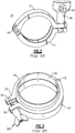
- Fig. 2 shows the clamp 10 closed together, but not installed on sanitary tubing. This view shows that the wing nut 28 leaves the threads the bolt shaft 26 open to the environment.
- Fig. 3 shows a similar C-clamp 28' in place on a pair of tube ends 30, with the wing nut 28' turned down to hold the wing nut in place against the jaw or radial finger 18.
- the wing nut 28' is a different style from the wing nut 28 of Fig. 1 , with a bore extending the length of the nut, and thus with the male threads of the bolt and the female threads of the wing nut 28' both exposed to the ambient and being a possible place where contaminates can collect.
- the improvement of the present invention can be explained with reference to the embodiment illustrated in Figs. 4 and 5 .
- the general structure of the C-clamp or tri-clamp 110 is similar to the prior-art embodiment of Figs. 1 and 2 , and elements similar to those in the sanitary clamp of Figs. 1 - 3 are identified by the same reference numbers, but raised by 100, and a detailed description can be omitted.
- the improvement here lies in the threaded fastener or closure 120, with a stepped swing bolt 126 and wing nut 128.
- the swing bolt 126 has a head or eye member 129 that is captured on a pivot pin 124 in the radially extending jaw or finger 122.
- the eye bolt or swing bolt 126 is of stepped construction, with a first smooth wall portion 130 of the shaft extending out from the eye or head 129 and a second, male-threaded tip portion 132.
- the tip member is stepped down, having a diameter smaller than the diameter of the first portion 130.
- the corresponding wing nut 128 has a blind, partly threaded bore 134, with a relatively wide initial portion 135 extending from the open end of the bore.
- This portion 135 has a predetermined diameter to approximately match the predetermined diameter of the smooth wall portion 130 of the bolt shaft.
- a narrower interior tip portion 16 of the wing nut bore continues from the end of the portion 135 along the same axis, and ends without penetrating the far end of the nut.
- This portion 136 has female threads to match the male threads of the tip portion 132 of the associated swing bolt.
- a seal ring 138 e.g., an O-ring seal or equivalent annular seal gland is situated in an annular cut out 139 adjacent the open end of the bore. As shown, with the wing nut 128 in place on the bolt 126, the seal ring 138 bears upon the smooth, unthreaded wall surface of the larger diameter portion 130 of the bolt, and effectively conceals all threads from the ambient.
- FIG. 6 An alternative construction for the sanitary clamp is shown in Fig. 6 , in which the clamp 210 is formed of a pair of mating ring halves 212 and 214 which are held together using a pair of threaded fastener devices 220, 220 one at each end of the facing ring halves.
- the fasteners each have a bolt member with a hex head 221 affixed on to the shaft 222, with the shaft having a larger-diameter smooth wall portion 226 and a smaller diameter threaded tip portion 232.
- the bolts are adapted to mate with the blind-bore wing nuts 128 of the type employed in the embodiment of Figs. 4 and 5 .
- Fig. 7 shows the bolt member 126 with an eye or pivot head 129, and a shaft with its initial smooth, unthreaded shaft portion 130 and a smaller diameter threaded tip portion 232, and with the associated wing nut 128 with the blind bore having an wide, smooth wall bore portion (provided without threads) 134 and smaller diameter female threaded tip portion 136 that does not penetrate the end of the nut.
- a seal ring 138 is seated into an annular seat 139 formed near the opening of the bore.
- Fig. 8 illustrates alternative construction of a generally equivalent threaded fastener arrangement with a bolt member having a hex head 229, a shaft 222 extending from the head and having a first, larger diameter smooth wall shaft portion 230 and a smaller-diameter male-threaded tip portion 232.
- a hex nut 228 has a plurality of flat grip surfaces to accept a wrench or a hex drive to turn the nut on the bolt.
- the nut has a stepped-diameter blind bore with a first, wider-diameter smooth wall portion 234 and a narrower-diameter female threaded tip portion 236.
- the two styles of nut 128 and 228 are interchangeable, and not specific to any bolt type.
- the bolts and nuts as shown here in Figs. 8 and 9 can have other applications beyond sanitary clamps, ie., anywhere that an application may demand that the fasteners have no exposed threads so as not to accumulate particulates or bacteria, or where there is any need to conceal threads behind a seal member so they are not exposed to the ambient.
- O-ring seal has been used in the foregoing examples, but there are many other seals and glands which are familiar in the art and which could be easily employed in other embodiments, for keeping threaded surfaces behind a seal in sanitary clamps or other applications.
Landscapes
- General Engineering & Computer Science (AREA)
- Engineering & Computer Science (AREA)
- Health & Medical Sciences (AREA)
- Mechanical Engineering (AREA)
- Life Sciences & Earth Sciences (AREA)
- Epidemiology (AREA)
- Birds (AREA)
- Animal Behavior & Ethology (AREA)
- General Health & Medical Sciences (AREA)
- Public Health (AREA)
- Veterinary Medicine (AREA)
- Inorganic Chemistry (AREA)
- Chemical & Material Sciences (AREA)
- Emergency Medicine (AREA)
- Clamps And Clips (AREA)
Description
- This invention relates to equipment for sanitary clamps for joining two flanged tubes or pipes together in a way that seals the junction of the two flanged ends and which allows the tubes and associated equipment to be cleaned in place by an injection of a cleaning fluid. The invention is more particularly concerned with a sanitary clamp that employs a threaded closure, e.g., a bolt or an eyebolt and an associated wing nut or hex nut to secure the clamp onto the flanged tube ends, and which when screwed down onto the clamp has no exposed screw threads, which can harbor bacteria or other contaminants and which are difficult to clean.
- There are a number of styles of sanitary clamps which go by names such as common tri-clamp, C-clamp, tri-clover, ferrule, sanitary ferrule, hygienic clamp, hygienic clamp ferrule, and hygienic clamp union.
- Over the past decade sanitary piping and sanitary vessels have received a great deal of scrutiny of their product design and the quality of finishes to optimize cleanability. Clamps of the type described have facilitated the cleaning of the interior of the sanitary flow line and any associated vessel or component. However, in more recent years that this scrutiny has been extended to the outside of piping and the outside of vessels, that is, to the entire clean area, including the exterior of the sanitary lines. Some sanitary lines including piping and vessels are now installed in clean manufacturing environments, i.e., clean rooms, where airborne particulate contamination has to be monitored and controlled. The response to this has been to improve the finishes and design of external components so they can be cleaned. Despite the increased interest in hygienic designs and avoiding structures and surfaces that may collect and harbor contaminates, there have been no major changes to the designs of sanitary clamps, which continue to be offered only with exposed threads.
- Equipment located in clean areas of food, dairy, or pharmaceutical processing or other comestible liquid processing environments are required to be cleaned periodically by wash-down, or manually cleaned by wipe-down with harsh cleaning solutions, i.e., caustics. All components of the food or other sanitary processing line have to be capable of being chemically cleaned or steam cleaned, and then rinsed in a pressure wash.
- Despite these requirements, designs for the sanitary clamp itself still employ closures with exposed threads which are notorious for collecting and harboring bacteria. Often a valve cluster or other processing equipment may have many sanitary clamps, which currently all have one or two bolt closures where there are exposed threads. This possible source of contamination in the clean environment has been overlooked and there has been no effort made to address it. These sanitary clamps employ either an eyebolt (swing bolt) and a wing nut or two common bolts and wing nuts or hex nuts, depending on the design. In either case these are fully threaded, and the wing nuts and hex nuts are of designs that leave their internal female threads exposed to the ambient, as well of the male threads of the threaded bolt shafts.
- With this construction it is not possible for all external exposed surfaces to be completely cleaned by washing it and rinsing it with a cleaning fluid, because of the difficulty in cleaning the threads. Any screw threads would have to be sealed off and isolated from any contact with the ambient atmosphere, but this issue has been completely overlooked in the sanitary clamp art.
-
US 2016/273572 A1 discloses a threaded fastener assembly of the prior art. -
US 5,653,481 discloses a sanitary clamp of the prior art. - It is an object of the present invention to provide an aseptic, sanitary, or hygienic clamp of straightforward construction, but with a closure designed to capable of being cleaned and with no threaded surfaces that are exposed to the ambient, so as to avoid the drawbacks, as previously mentioned, that affect the sanitary clamps of the prior art.
- It is another object to provide an aseptic, sanitary, or hygienic clamp that can be easily installed and where the required bolts and nuts can be interchanged with those on existing sanitary clamps.
- The invention is defined by a threaded fastener assembly according to claim 1.
- According to a preferred embodiment, a sanitary clamp has an annulus or ring formed of facing ring halves, each ring half with an annular channel to fit over the flanges of a pair of flanged round members, such as flanged tube ends or a flanged end cap and a flanged tube. The ring halves each are also formed so as to have a jaw in the form of a radially protruding finger, with a bolt slot, with the finger extending radially out from the associated ring half The ring halves can be hinged to close together, or they can have the extending fingers on both sides so they are held together with a bolt and nut on each side. These are pulled together to close up the facing pair of flanged round members. Typically a gasket or gland is placed between tube ends to ensure the tube ends are in sealed engagement with one another.
- A bolt member is configured to penetrate the fingers (e.g., through the bolt slot) for closing them towards one another. The bolt member has a head (which can be a ring or eye, or can be a hex head, for example) and a shaft or shank. The shaft has a first smooth shaft portion extending from the head, with a smooth unthreaded wall surface and a first predetermined diameter. Then there is a male-threaded tip portion extending from the smooth shaft portion and aligned coaxial with it. This tip portion has a male spiral thread thereon, and in some embodiments may be necked down or reduced, i.e., so it has a second diameter smaller than the first diameter, i.e., smaller than the diameter of the smooth first shaft portion. In other embodiments, the smooth shaft portion and the threaded tip may have the same diameter. The cooperating nut member is designed to thread onto this bolt member and draw the finger members towards one another to bring the ring halves into sealing engagement with the flanged tube ends. The nut member has a blind bore that extends from a first end of the nut, and does not penetrate out the other end. This blind bore has a first smooth wall portion of a first predetermined bore diameter corresponding with the diameter of the bolt's smooth shaft portion, to admit entry of the smooth shaft portion, and then has a second female-threaded bore portion extending coaxial with the first smooth wall bore portion with a diameter to match the tip of the bolt member. Here, the threaded bore portion has a diameter smaller than the first predetermined bore diameter. This portion is designed and adapted for making threaded engagement with the tip portion of the bolt member.
- In order to ensure that all the threads are concealed and no threads are exposed, the bore of the nut is open only at said first end of the nut member, and a seal member or gland, e.g., a ring seal or O-ring, is disposed within the first smooth wall bore portion of the nut member adjacent said free end. When the nut member is installed onto the bolt member, this seal ring closes off a space that contains the tip portion of the bolt member and the female threaded bore portion. Thus, there are no threads of the bolt member or of the nut member that are exposed to the ambient. Consequently, the remaining exposed surfaces, free of threads, can be easily cleansed of any microbial contaminates.
- Depending on the design the nut member can take the form of a wing nut having a pair of radially protruding wing members, or may take the form of a hex nut having a plurality of engaging surfaces on a its circumference or in a central recess in some cases. Other types of nuts are possible, such as those that accept an alien wrench, or another wrench or key.
- The threaded fastener assembly of the invention can be used in other applications where it is necessary to conceal the threads and seal them off from the ambient. Here, the bolt has a head and a shaft that is threaded along a tip portion and is smooth (ie., provided without engaging threads) along a portion near the head, as described above, and the nut has a blind bore, ie., open only at one end, that is smooth walled (ie., no engaging threads) along a first portion and threaded along a second portion to accommodate the shaft of the bolt, and a seal or gland is disposed in an annular seat within the bore near the opening to seal against the smooth portion of the bolt shaft and to seal off the threads of the shaft and nut from the ambient. Any roughness or texture on the smooth first portion that is distal of the seal would be protected from the ambient.
- The bolt member shaft has a first smooth shaft portion extending from the head, with a smooth unthreaded wall surface and a first predetermined diameter. A male-threaded tip portion extends from the smooth shaft portion and aligns coaxially with it. This tip portion has a male spiral thread thereon, and here is shouldered or necked down to a second diameter smaller than the first diameter, that is, the diameter of the smooth first shaft portion. The cooperating nut member is designed to thread onto this bolt member, with a blind bore that extends from a first end of the nut, and does not penetrate out the other end. This blind bore has a first smooth wall portion of a first predetermined bore diameter corresponding with the diameter of the bolt's smooth shaft portion, to admit entry of the smooth shaft portion, and then has a second female-threaded bore portion extending coaxial with the first smooth wall bore portion and having a diameter to correspond to the tip portion of the bolt member. Here, this diameter is smaller than the first predetermined bore diameter. The tip portion makes threaded engagement with the tip portion of the bolt member. The O-ring, annular seal gland, or other sealing gasket or gland can be disposed in an annular cutout formed in the wall of the blind bore near the opening, so all threads are concealed from the environment once the nut is installed and tightened down onto the shaft. This arrangement can be employed on pipe hangers, attachments, and other equipment, and is not limited only to use with C-clamps or other sanitary clamps.
- The above and many other objects, features, and advantages of the arrangements of the present invention will become apparent from the ensuing detailed description of preferred embodiments of the invention, when read in connection with the accompanying drawings.
-
-
Fig. 1 is perspective view of an example of sanitary clamp according to the prior art, shown open to explain its general construction. -
Figs. 2 and 3 are perspective views of sanitary clamps according to the prior art. -
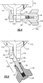
Fig. 4 is a partial elevational view of the a sanitary clamp according to one exemplary embodiment of this invention, showing portions of the bolt and nut in broken line. -
Fig. 5 is another elevational view thereof showing a portion of the bolt shaft and the associated nut in cross-section. -
Fig. 6 illustrates a sanitary clamp according to another embodiment of the invention. -
Figs. 7 and 8 are examples of bolts and mating nut members that embody the present invention. - With initial reference to
Figs. 1 to 3 , a sanitary clamp, ie., a standard C-clamp ortri-clamp 10 of the prior art is presented as a standard device for joining pipe ends for processing equipment joined to a sanitary conduit, for example in a process for a dairy product, another edible product such as fruit juice, sauce or soup, or a pharmaceutical product for human or veterinary use, or a cosmetic, beauty-related, or dermatological creme or liquid. Typically there are many of these sanitary clamps employed in any commercial processing operation of this type. - The
sanitary clamp 10 of this example has first and second ring halves 12 and 15 joined at proximal ends at aclamp hinge member 16, with anopen jaw member 18 projecting as a radial finger from the proximal end of thering half 12, with a bolt slot 19 extending along thejaw member 18. A threadedclosure member 20, here aswing bolt 26 oreye bolt 26, has a head or eye captured on a pivot pin orhinge pin 24 to attach it into a bolt slot of aradial finger 22 at the proximal end of theother ring half 14. In this case the swing bolt oreye bolt 26 is threaded along the entire length of the shaft, and a thumb screw orwing nut 28 is threaded onto the shaft and turned down to clamp the C-clamp or tri-clamp closed. - As shown in
Fig. 1 , this clamp is used to hold together a pair of flanged tube ends 30, with a seal orgland 32 placed between them The flanges are captured in an annular channel formed in the tworing halves -
Fig. 2 shows theclamp 10 closed together, but not installed on sanitary tubing. This view shows that thewing nut 28 leaves the threads thebolt shaft 26 open to the environment. -
Fig. 3 shows a similar C-clamp 28' in place on a pair of tube ends 30, with thewing nut 28' turned down to hold the wing nut in place against the jaw orradial finger 18. In this case thewing nut 28' is a different style from thewing nut 28 ofFig. 1 , with a bore extending the length of the nut, and thus with the male threads of the bolt and the female threads of thewing nut 28' both exposed to the ambient and being a possible place where contaminates can collect. - The improvement of the present invention can be explained with reference to the embodiment illustrated in
Figs. 4 and 5 . Here, the general structure of the C-clamp ortri-clamp 110 is similar to the prior-art embodiment ofFigs. 1 and2 , and elements similar to those in the sanitary clamp ofFigs. 1 - 3 are identified by the same reference numbers, but raised by 100, and a detailed description can be omitted. The improvement here lies in the threaded fastener orclosure 120, with a steppedswing bolt 126 andwing nut 128. Theswing bolt 126 has a head oreye member 129 that is captured on apivot pin 124 in the radially extending jaw orfinger 122. The eye bolt orswing bolt 126 is of stepped construction, with a firstsmooth wall portion 130 of the shaft extending out from the eye orhead 129 and a second, male-threadedtip portion 132. The tip member is stepped down, having a diameter smaller than the diameter of thefirst portion 130. - The
corresponding wing nut 128 has a blind, partly threadedbore 134, with a relatively wide initial portion 135 extending from the open end of the bore. This portion 135 has a predetermined diameter to approximately match the predetermined diameter of thesmooth wall portion 130 of the bolt shaft. A narrowerinterior tip portion 16 of the wing nut bore continues from the end of the portion 135 along the same axis, and ends without penetrating the far end of the nut. Thisportion 136 has female threads to match the male threads of thetip portion 132 of the associated swing bolt. To isolate the male and female threads of thetip portions seal ring 138, e.g., an O-ring seal or equivalent annular seal gland is situated in an annular cut out 139 adjacent the open end of the bore. As shown, with thewing nut 128 in place on thebolt 126, theseal ring 138 bears upon the smooth, unthreaded wall surface of thelarger diameter portion 130 of the bolt, and effectively conceals all threads from the ambient. - The construction of the swing bolt and nut is simple, but robust, without requiring complex shapes, and the bolt can be changed out to replace a standard swing bolt in an existing sanitary clamp of the type shown in
Figs. 1 to 3 . Thus, these improved clamps and closures are relatively inexpensive to manufacture, and simple to install and maintain. - An alternative construction for the sanitary clamp is shown in
Fig. 6 , in which theclamp 210 is formed of a pair of mating ring halves 212 and 214 which are held together using a pair of threadedfastener devices hex head 221 affixed on to theshaft 222, with the shaft having a larger-diametersmooth wall portion 226 and a smaller diameter threadedtip portion 232. The bolts are adapted to mate with the blind-bore wing nuts 128 of the type employed in the embodiment ofFigs. 4 and 5 . - Alternative constructions for the threaded fasteners, apart from the sanitary clamps, are illustrated in
Figs. 7 and 8 . -
Fig. 7 shows thebolt member 126 with an eye orpivot head 129, and a shaft with its initial smooth,unthreaded shaft portion 130 and a smaller diameter threadedtip portion 232, and with the associatedwing nut 128 with the blind bore having an wide, smooth wall bore portion (provided without threads) 134 and smaller diameter female threadedtip portion 136 that does not penetrate the end of the nut. As described earlier, aseal ring 138 is seated into anannular seat 139 formed near the opening of the bore. -
Fig. 8 illustrates alternative construction of a generally equivalent threaded fastener arrangement with a bolt member having ahex head 229, ashaft 222 extending from the head and having a first, larger diameter smoothwall shaft portion 230 and a smaller-diameter male-threadedtip portion 232. Here, ahex nut 228 has a plurality of flat grip surfaces to accept a wrench or a hex drive to turn the nut on the bolt. As in the other embodiment(s), the nut has a stepped-diameter blind bore with a first, wider-diametersmooth wall portion 234 and a narrower-diameter female threadedtip portion 236. - The two styles of
nut - The bolts and nuts as shown here in
Figs. 8 and 9 can have other applications beyond sanitary clamps, ie., anywhere that an application may demand that the fasteners have no exposed threads so as not to accumulate particulates or bacteria, or where there is any need to conceal threads behind a seal member so they are not exposed to the ambient. - An O-ring seal has been used in the foregoing examples, but there are many other seals and glands which are familiar in the art and which could be easily employed in other embodiments, for keeping threaded surfaces behind a seal in sanitary clamps or other applications.
- While the invention has been described with reference to a number of preferred embodiments, it should be understood that the invention is not limited only to those embodiments. Rather many variations are possible without departing from the scope of this invention, as defined in the appended Claims.
Claims (7)
- A threaded fastener assembly for use in an environment in which threads exposed to the ambient must be avoided, comprising:a bolt member (126) having a head and a shaft (130) that includes a first smooth shaft portion (134) extending from said head having a smooth unthreaded wall surface and a first predetermined diameter, and a male-threaded tip portion (132) extending from said smooth shaft portion and coaxial with it, with a male spiral thread thereon, and having a second diameter;a nut member (128) configured for threadably engaging said bolt member (126) and having a blind bore (134) extending from a first end of the nut and opening only at said first end, the bore having a first smooth wall portion (135) of a first predetermined bore diameter to admit entry of the first smooth shaft portion (130) of said bolt member (126), and a second female-threaded bore portion (136) extending coaxial with the first smooth wall bore portion (135) and having a female spiral thread adapted for threaded engagement with the tip portion (132) of said bolt member; whereina seal member (138) is disposed within said first smooth wall bore portion of said nut member adjacent said first end;the bore (134) of said nut member (128) is a stepped bore wherein said first diameter thereof is larger than the second diameter thereof and wherein said bolt member (126) is stepped such that the first diameter thereof (130) is larger than said second diameter of said male-threaded tip portion (132), andwherein said seal member is an annular seal which is fitted into an annular channel (139) formed in the first smooth wall bore portion (135), such that once said nut member (128) is fastened onto said bolt member (126), said seal member (138) closes off a space defined between said the tip portion of said bolt member and the female threaded bore portion, such that the male and female spiral threads of the bolt member and the nut member are entirely concealed.
- The threaded fastener assembly according to claim 1, further comprising a sanitary clamp comprising
a ring (10,110, 210) formed of facing ring halves (12,14,112,114, 212, 214), each ring half having a radially protruding finger (18,118) that extends out from the associated ring half, the ring halves being adapted for closing together onto a pair of flanged round members for holding the round members in sealed engagement with one another;
said bolt member (126, 226) being adapted to penetrate said fingers in proximity to one another; and
said nut member (128, 228) threadably engaging said bolt member and drawing said finger members towards one another to bring the ring halves into sealing engagement with said flanged round members; and
said seal member (138, 238) being disposed within said first smooth wall bore portion of said nut member adjacent said first end, such that once said nut member is fastened onto said bolt member, said seal member closes off and seals the space defined between said the tip portion of said bolt member and the female threaded bore portion, of said nut member. - The threaded fastener assembly according to any preceding claim, wherein said nut member is in the form of a wing nut (128) having a plurality of wing members projecting therefrom.
- The threaded fastener assembly according to claim 3, wherein said wing nut (128) has a pair of wing members (128) protruding radially therefrom.
- The threaded fastener assembly according to claim 1 or 2, wherein said nut has a head (228) that includes a plurality of flat engaging surface adapted to fit a wrench or driver.
- The threaded fastener assembly according to claim 1 or 2, wherein said nut is in the form of a hex nut (228) having a plurality of flat engaging surfaces on a circumference thereof.
- The threaded fastener assembly according to any preceding claim wherein said male threaded tip portion (132, 232) of said bolt member is necked down from said first smooth shaft portion (130, 230) thereof.
Applications Claiming Priority (2)
| Application Number | Priority Date | Filing Date | Title |
|---|---|---|---|
| US15/345,717 US9927052B1 (en) | 2016-11-08 | 2016-11-08 | Sanitary clamp with concealed threads |
| PCT/US2017/060147 WO2018089298A1 (en) | 2016-11-08 | 2017-11-06 | Sanitary clamp with concealed threads |
Publications (2)
| Publication Number | Publication Date |
|---|---|
| EP3538805A1 EP3538805A1 (en) | 2019-09-18 |
| EP3538805B1 true EP3538805B1 (en) | 2021-01-27 |
Family
ID=61633266
Family Applications (1)
| Application Number | Title | Priority Date | Filing Date |
|---|---|---|---|
| EP17808653.4A Active EP3538805B1 (en) | 2016-11-08 | 2017-11-06 | Threaded fastener assembly with concealed threads |
Country Status (5)
| Country | Link |
|---|---|
| US (1) | US9927052B1 (en) |
| EP (1) | EP3538805B1 (en) |
| CN (1) | CN110268186B (en) |
| ES (1) | ES2859672T3 (en) |
| WO (1) | WO2018089298A1 (en) |
Families Citing this family (12)
| Publication number | Priority date | Publication date | Assignee | Title |
|---|---|---|---|---|
| US10639237B2 (en) * | 2018-09-13 | 2020-05-05 | Ge Healthcare Bio-Sciences Corp. | Aseptic connectors with integrated wireless connectivity |
| US12152406B2 (en) * | 2020-01-10 | 2024-11-26 | Triangle Brass Manufacturing Company, Inc. | Adjustable and configurable standoff |
| US12379056B1 (en) | 2020-06-09 | 2025-08-05 | The United States Of America, As Represented By The Secretary Of The Navy | Dual cam lever hose clamp |
| US12078270B1 (en) | 2020-06-09 | 2024-09-03 | The United States Of America, As Represented By The Secretary Of The Navy | Dual cam lever hose clamp and methods of use thereof |
| US11585475B1 (en) * | 2020-06-09 | 2023-02-21 | The United States Of America, As Represented By The Secretary Of The Navy | Dual cam lever hose clamp |
| USD1026637S1 (en) * | 2020-08-27 | 2024-05-14 | Wilmarc Holdings, Llc | Clamp |
| CN114476617B (en) * | 2020-10-27 | 2025-04-22 | 中核建中核燃料元件有限公司 | Fuel rod unloading tilting rack |
| US11965613B2 (en) * | 2020-10-27 | 2024-04-23 | Zeta Gmbh | System and a method for providing a sterile fluid connection between a first fluid channel and a second fluid channel |
| US12455026B2 (en) * | 2020-11-30 | 2025-10-28 | Graco Minnesota Inc. | Sanitary clamp for diaphragm pump covers |
| AU2022410587A1 (en) | 2021-12-17 | 2024-06-20 | Lubrizol Advanced Materials, Inc. | Pipe apparatus, coupling devices, and methods |
| US11629804B1 (en) | 2022-04-20 | 2023-04-18 | Carolina Components Group, Inc. | Asymmetric clamp for joining sanitary fittings |
| CN115603240A (en) * | 2022-09-16 | 2023-01-13 | 北京特种机械研究所(Cn) | Multi-cable fixing clamp capable of being rapidly disassembled and using method |
Family Cites Families (34)
| Publication number | Priority date | Publication date | Assignee | Title |
|---|---|---|---|---|
| US2689141A (en) * | 1952-01-07 | 1954-09-14 | Elmer C Kiekhaefer | Adjustable ring clamp |
| US3534988A (en) * | 1968-11-15 | 1970-10-20 | Ite Imperial Corp | Tube end mounted sleeve |
| US3966240A (en) * | 1974-06-04 | 1976-06-29 | Nakamura Kinzoku Kogyosho, Inc. | Quick-action pipe joint |
| US4472097A (en) | 1981-03-20 | 1984-09-18 | Farathane, Inc. | Torque limiting elastomeric fastener and seal |
| US4472098A (en) | 1981-03-20 | 1984-09-18 | Farathane, Inc. | Torque limiting elastomeric fastener for screw threaded member |
| US4492817A (en) | 1982-03-01 | 1985-01-08 | Square D Company | Watertight bushing and bolt mounting assembly |
| GB8503731D0 (en) | 1985-02-14 | 1985-03-20 | Beloit Walmsley Ltd | Sealing of bolted assemblies in fluid containers |
| US4788022A (en) | 1985-02-22 | 1988-11-29 | Bridgestone Corp. | Method of manufacturing waterproof nuts |
| US4802700B1 (en) * | 1987-11-09 | 1996-10-01 | Transguard Ind Inc | Locking seal |
| US5098241A (en) | 1991-02-05 | 1992-03-24 | Xyzyx International Corp. | Variable length telescopic connector and method for use |
| USRE35358E (en) * | 1992-05-29 | 1996-10-22 | Belser; Jess L. | Fastening bolt assembly with anti-rotation device and providing both axial and radial holding forces |
| US5553984A (en) | 1995-01-10 | 1996-09-10 | Smith; Donald E. | Encapsulated nut |
| US5653481A (en) * | 1996-02-09 | 1997-08-05 | United Dominion Industries, Inc. | Pipe clamp with live loading nut assembly |
| US6347708B1 (en) | 1999-03-22 | 2002-02-19 | Cedarapids Inc. | Wheel case for a vibratory apparatus |
| DE19946578A1 (en) * | 1999-09-29 | 2001-04-05 | Hilti Ag | Quick connection system for threaded rods |
| GB9925469D0 (en) * | 1999-10-27 | 1999-12-29 | Boc Group Plc | Seal assemblies |
| GB2362428B (en) * | 1999-11-17 | 2002-04-24 | Jarzon Plastics Ltd | Nut and seat assembly for clamp |
| US6244807B1 (en) | 2000-03-06 | 2001-06-12 | Bristol Industries | Double seal nut |
| US6523866B2 (en) * | 2001-06-06 | 2003-02-25 | Peter Lin | Constant tension clamping device for flanged connections |
| WO2003046392A2 (en) * | 2001-11-21 | 2003-06-05 | Bal Seal Engineering Co., Inc. | Connector with radial spring |
| US7077611B2 (en) | 2003-05-09 | 2006-07-18 | Fisher Controls International Llc. | O-ring forming sealing washer |
| US7318390B2 (en) | 2003-10-20 | 2008-01-15 | Ron Amy | Deck mounted device with gasket |
| US7086131B2 (en) * | 2004-05-14 | 2006-08-08 | Victaulic Company | Deformable mechanical pipe coupling |
| US20050258648A1 (en) * | 2004-05-24 | 2005-11-24 | Newman Sanitary Gasket Company | Clamp assembly for joining two annular ferrules |
| US7883121B2 (en) * | 2005-02-18 | 2011-02-08 | Advanced Couplings Limited | Pipe coupling clamp |
| US7766391B2 (en) * | 2006-04-05 | 2010-08-03 | Doowon Climate Control Co., Ltd. | Pipe connecting structure |
| US8240718B2 (en) | 2006-07-28 | 2012-08-14 | Hitco, Inc. | Sanitary quick connector |
| US8328458B2 (en) * | 2007-07-20 | 2012-12-11 | Twin Bay Medical, Inc. | Sanitary clamp |
| US8371623B2 (en) | 2010-01-07 | 2013-02-12 | Herve′ X. Bronnert | Cam clamp assembly |
| US8220113B2 (en) | 2010-11-19 | 2012-07-17 | Hitco, Ltd. | Smart clamp device for connecting tubing |
| JP5456853B2 (en) * | 2012-07-25 | 2014-04-02 | アイシン高丘株式会社 | Clamping device |
| DE202014007293U1 (en) * | 2014-09-12 | 2014-10-06 | Rema Tip Top Ag | Nut for a clamping device of a Vulkanisierpresse, a clamping device, a Vulkanisierpresse and a support device for components of a Vulkanisierpresse |
| GB2536471A (en) * | 2015-03-18 | 2016-09-21 | Airbus Operations Ltd | Self-sealing fixing element |
| CN104847981A (en) * | 2015-06-12 | 2015-08-19 | 上海中船三井造船柴油机有限公司 | Connecting apparatus of dual-wall high-pressure gas pipelines |
-
2016
- 2016-11-08 US US15/345,717 patent/US9927052B1/en active Active
-
2017
- 2017-11-06 CN CN201780082529.4A patent/CN110268186B/en active Active
- 2017-11-06 EP EP17808653.4A patent/EP3538805B1/en active Active
- 2017-11-06 ES ES17808653T patent/ES2859672T3/en active Active
- 2017-11-06 WO PCT/US2017/060147 patent/WO2018089298A1/en not_active Ceased
Non-Patent Citations (1)
| Title |
|---|
| None * |
Also Published As
| Publication number | Publication date |
|---|---|
| CN110268186B (en) | 2021-05-11 |
| WO2018089298A1 (en) | 2018-05-17 |
| ES2859672T3 (en) | 2021-10-04 |
| CN110268186A (en) | 2019-09-20 |
| US9927052B1 (en) | 2018-03-27 |
| EP3538805A1 (en) | 2019-09-18 |
Similar Documents
| Publication | Publication Date | Title |
|---|---|---|
| US9927052B1 (en) | Sanitary clamp with concealed threads | |
| CN109154411B (en) | Cam type sanitary fixture | |
| JPH03177690A (en) | Connector for multiline | |
| CA2666726A1 (en) | Valve assembly and system | |
| JPWO2012144072A1 (en) | Member joint and spray nozzle unit using the same | |
| US2443394A (en) | Coupling for hoses and pipes | |
| CN104390080B (en) | Pipe joint connection structure and pipe joint adopting structure | |
| JPH08105580A (en) | Pipe joint locking device | |
| JPH02102988A (en) | Connector for piping | |
| JP2002048277A (en) | Pipe fitting | |
| JPH0552282A (en) | Device for connecting fluid system two section | |
| EP2196715B1 (en) | A compression fitting | |
| US11815730B2 (en) | Sanitary in-line sight glass assembly | |
| JPH0862079A (en) | Pressure sensor mounting device | |
| US4850615A (en) | Multi-pipe trap adapter | |
| US6874373B1 (en) | Mass flowmeter having a connecting element and a reinforcing element | |
| CN104895883A (en) | Screw nut and screw bolt combination mechanism | |
| US11525535B1 (en) | Toolless disassembly rotational vacuum coupling | |
| US20220275892A1 (en) | Connector for flexible tubing | |
| CN218378115U (en) | Flaring connecting joint for ultrapure PFA pipeline | |
| JPS6217478A (en) | Needle valve | |
| EP0292165A2 (en) | Hose pipe | |
| CN209180355U (en) | A kind of fastening seal structure for airtight valve | |
| JPH0425598Y2 (en) | ||
| US2188515A (en) | Sanitary fitting for thermometer bulbs |
Legal Events
| Date | Code | Title | Description |
|---|---|---|---|
| STAA | Information on the status of an ep patent application or granted ep patent |
Free format text: STATUS: UNKNOWN |
|
| STAA | Information on the status of an ep patent application or granted ep patent |
Free format text: STATUS: THE INTERNATIONAL PUBLICATION HAS BEEN MADE |
|
| PUAI | Public reference made under article 153(3) epc to a published international application that has entered the european phase |
Free format text: ORIGINAL CODE: 0009012 |
|
| STAA | Information on the status of an ep patent application or granted ep patent |
Free format text: STATUS: REQUEST FOR EXAMINATION WAS MADE |
|
| 17P | Request for examination filed |
Effective date: 20190531 |
|
| AK | Designated contracting states |
Kind code of ref document: A1 Designated state(s): AL AT BE BG CH CY CZ DE DK EE ES FI FR GB GR HR HU IE IS IT LI LT LU LV MC MK MT NL NO PL PT RO RS SE SI SK SM TR |
|
| AX | Request for extension of the european patent |
Extension state: BA ME |
|
| DAV | Request for validation of the european patent (deleted) | ||
| DAX | Request for extension of the european patent (deleted) | ||
| GRAP | Despatch of communication of intention to grant a patent |
Free format text: ORIGINAL CODE: EPIDOSNIGR1 |
|
| STAA | Information on the status of an ep patent application or granted ep patent |
Free format text: STATUS: GRANT OF PATENT IS INTENDED |
|
| INTG | Intention to grant announced |
Effective date: 20200630 |
|
| GRAJ | Information related to disapproval of communication of intention to grant by the applicant or resumption of examination proceedings by the epo deleted |
Free format text: ORIGINAL CODE: EPIDOSDIGR1 |
|
| STAA | Information on the status of an ep patent application or granted ep patent |
Free format text: STATUS: REQUEST FOR EXAMINATION WAS MADE |
|
| RAP1 | Party data changed (applicant data changed or rights of an application transferred) |
Owner name: FELDMEIER EQUIPMENT, INCORPORATED |
|
| GRAS | Grant fee paid |
Free format text: ORIGINAL CODE: EPIDOSNIGR3 |
|
| STAA | Information on the status of an ep patent application or granted ep patent |
Free format text: STATUS: GRANT OF PATENT IS INTENDED |
|
| GRAP | Despatch of communication of intention to grant a patent |
Free format text: ORIGINAL CODE: EPIDOSNIGR1 |
|
| INTC | Intention to grant announced (deleted) | ||
| INTG | Intention to grant announced |
Effective date: 20201125 |
|
| GRAA | (expected) grant |
Free format text: ORIGINAL CODE: 0009210 |
|
| STAA | Information on the status of an ep patent application or granted ep patent |
Free format text: STATUS: THE PATENT HAS BEEN GRANTED |
|
| AK | Designated contracting states |
Kind code of ref document: B1 Designated state(s): AL AT BE BG CH CY CZ DE DK EE ES FI FR GB GR HR HU IE IS IT LI LT LU LV MC MK MT NL NO PL PT RO RS SE SI SK SM TR |
|
| REG | Reference to a national code |
Ref country code: GB Ref legal event code: FG4D |
|
| REG | Reference to a national code |
Ref country code: CH Ref legal event code: EP |
|
| REG | Reference to a national code |
Ref country code: AT Ref legal event code: REF Ref document number: 1358647 Country of ref document: AT Kind code of ref document: T Effective date: 20210215 |
|
| REG | Reference to a national code |
Ref country code: IE Ref legal event code: FG4D |
|
| REG | Reference to a national code |
Ref country code: DE Ref legal event code: R096 Ref document number: 602017032193 Country of ref document: DE |
|
| REG | Reference to a national code |
Ref country code: NL Ref legal event code: MP Effective date: 20210127 |
|
| REG | Reference to a national code |
Ref country code: LT Ref legal event code: MG9D |
|
| REG | Reference to a national code |
Ref country code: AT Ref legal event code: MK05 Ref document number: 1358647 Country of ref document: AT Kind code of ref document: T Effective date: 20210127 |
|
| PG25 | Lapsed in a contracting state [announced via postgrant information from national office to epo] |
Ref country code: PT Free format text: LAPSE BECAUSE OF FAILURE TO SUBMIT A TRANSLATION OF THE DESCRIPTION OR TO PAY THE FEE WITHIN THE PRESCRIBED TIME-LIMIT Effective date: 20210527 Ref country code: NO Free format text: LAPSE BECAUSE OF FAILURE TO SUBMIT A TRANSLATION OF THE DESCRIPTION OR TO PAY THE FEE WITHIN THE PRESCRIBED TIME-LIMIT Effective date: 20210427 Ref country code: FI Free format text: LAPSE BECAUSE OF FAILURE TO SUBMIT A TRANSLATION OF THE DESCRIPTION OR TO PAY THE FEE WITHIN THE PRESCRIBED TIME-LIMIT Effective date: 20210127 Ref country code: GR Free format text: LAPSE BECAUSE OF FAILURE TO SUBMIT A TRANSLATION OF THE DESCRIPTION OR TO PAY THE FEE WITHIN THE PRESCRIBED TIME-LIMIT Effective date: 20210428 Ref country code: HR Free format text: LAPSE BECAUSE OF FAILURE TO SUBMIT A TRANSLATION OF THE DESCRIPTION OR TO PAY THE FEE WITHIN THE PRESCRIBED TIME-LIMIT Effective date: 20210127 Ref country code: BG Free format text: LAPSE BECAUSE OF FAILURE TO SUBMIT A TRANSLATION OF THE DESCRIPTION OR TO PAY THE FEE WITHIN THE PRESCRIBED TIME-LIMIT Effective date: 20210427 Ref country code: LT Free format text: LAPSE BECAUSE OF FAILURE TO SUBMIT A TRANSLATION OF THE DESCRIPTION OR TO PAY THE FEE WITHIN THE PRESCRIBED TIME-LIMIT Effective date: 20210127 |
|
| PG25 | Lapsed in a contracting state [announced via postgrant information from national office to epo] |
Ref country code: AT Free format text: LAPSE BECAUSE OF FAILURE TO SUBMIT A TRANSLATION OF THE DESCRIPTION OR TO PAY THE FEE WITHIN THE PRESCRIBED TIME-LIMIT Effective date: 20210127 Ref country code: RS Free format text: LAPSE BECAUSE OF FAILURE TO SUBMIT A TRANSLATION OF THE DESCRIPTION OR TO PAY THE FEE WITHIN THE PRESCRIBED TIME-LIMIT Effective date: 20210127 Ref country code: LV Free format text: LAPSE BECAUSE OF FAILURE TO SUBMIT A TRANSLATION OF THE DESCRIPTION OR TO PAY THE FEE WITHIN THE PRESCRIBED TIME-LIMIT Effective date: 20210127 Ref country code: PL Free format text: LAPSE BECAUSE OF FAILURE TO SUBMIT A TRANSLATION OF THE DESCRIPTION OR TO PAY THE FEE WITHIN THE PRESCRIBED TIME-LIMIT Effective date: 20210127 Ref country code: SE Free format text: LAPSE BECAUSE OF FAILURE TO SUBMIT A TRANSLATION OF THE DESCRIPTION OR TO PAY THE FEE WITHIN THE PRESCRIBED TIME-LIMIT Effective date: 20210127 |
|
| PG25 | Lapsed in a contracting state [announced via postgrant information from national office to epo] |
Ref country code: IS Free format text: LAPSE BECAUSE OF FAILURE TO SUBMIT A TRANSLATION OF THE DESCRIPTION OR TO PAY THE FEE WITHIN THE PRESCRIBED TIME-LIMIT Effective date: 20210527 |
|
| REG | Reference to a national code |
Ref country code: ES Ref legal event code: FG2A Ref document number: 2859672 Country of ref document: ES Kind code of ref document: T3 Effective date: 20211004 |
|
| REG | Reference to a national code |
Ref country code: DE Ref legal event code: R097 Ref document number: 602017032193 Country of ref document: DE |
|
| PG25 | Lapsed in a contracting state [announced via postgrant information from national office to epo] |
Ref country code: CZ Free format text: LAPSE BECAUSE OF FAILURE TO SUBMIT A TRANSLATION OF THE DESCRIPTION OR TO PAY THE FEE WITHIN THE PRESCRIBED TIME-LIMIT Effective date: 20210127 Ref country code: EE Free format text: LAPSE BECAUSE OF FAILURE TO SUBMIT A TRANSLATION OF THE DESCRIPTION OR TO PAY THE FEE WITHIN THE PRESCRIBED TIME-LIMIT Effective date: 20210127 Ref country code: SM Free format text: LAPSE BECAUSE OF FAILURE TO SUBMIT A TRANSLATION OF THE DESCRIPTION OR TO PAY THE FEE WITHIN THE PRESCRIBED TIME-LIMIT Effective date: 20210127 |
|
| PG25 | Lapsed in a contracting state [announced via postgrant information from national office to epo] |
Ref country code: DK Free format text: LAPSE BECAUSE OF FAILURE TO SUBMIT A TRANSLATION OF THE DESCRIPTION OR TO PAY THE FEE WITHIN THE PRESCRIBED TIME-LIMIT Effective date: 20210127 Ref country code: SK Free format text: LAPSE BECAUSE OF FAILURE TO SUBMIT A TRANSLATION OF THE DESCRIPTION OR TO PAY THE FEE WITHIN THE PRESCRIBED TIME-LIMIT Effective date: 20210127 Ref country code: RO Free format text: LAPSE BECAUSE OF FAILURE TO SUBMIT A TRANSLATION OF THE DESCRIPTION OR TO PAY THE FEE WITHIN THE PRESCRIBED TIME-LIMIT Effective date: 20210127 |
|
| PLBE | No opposition filed within time limit |
Free format text: ORIGINAL CODE: 0009261 |
|
| STAA | Information on the status of an ep patent application or granted ep patent |
Free format text: STATUS: NO OPPOSITION FILED WITHIN TIME LIMIT |
|
| 26N | No opposition filed |
Effective date: 20211028 |
|
| PG25 | Lapsed in a contracting state [announced via postgrant information from national office to epo] |
Ref country code: AL Free format text: LAPSE BECAUSE OF FAILURE TO SUBMIT A TRANSLATION OF THE DESCRIPTION OR TO PAY THE FEE WITHIN THE PRESCRIBED TIME-LIMIT Effective date: 20210127 |
|
| PG25 | Lapsed in a contracting state [announced via postgrant information from national office to epo] |
Ref country code: SI Free format text: LAPSE BECAUSE OF FAILURE TO SUBMIT A TRANSLATION OF THE DESCRIPTION OR TO PAY THE FEE WITHIN THE PRESCRIBED TIME-LIMIT Effective date: 20210127 |
|
| PG25 | Lapsed in a contracting state [announced via postgrant information from national office to epo] |
Ref country code: IT Free format text: LAPSE BECAUSE OF FAILURE TO SUBMIT A TRANSLATION OF THE DESCRIPTION OR TO PAY THE FEE WITHIN THE PRESCRIBED TIME-LIMIT Effective date: 20210127 |
|
| PG25 | Lapsed in a contracting state [announced via postgrant information from national office to epo] |
Ref country code: IS Free format text: LAPSE BECAUSE OF FAILURE TO SUBMIT A TRANSLATION OF THE DESCRIPTION OR TO PAY THE FEE WITHIN THE PRESCRIBED TIME-LIMIT Effective date: 20210527 |
|
| PG25 | Lapsed in a contracting state [announced via postgrant information from national office to epo] |
Ref country code: MC Free format text: LAPSE BECAUSE OF FAILURE TO SUBMIT A TRANSLATION OF THE DESCRIPTION OR TO PAY THE FEE WITHIN THE PRESCRIBED TIME-LIMIT Effective date: 20210127 |
|
| REG | Reference to a national code |
Ref country code: CH Ref legal event code: PL |
|
| PG25 | Lapsed in a contracting state [announced via postgrant information from national office to epo] |
Ref country code: LU Free format text: LAPSE BECAUSE OF NON-PAYMENT OF DUE FEES Effective date: 20211106 Ref country code: BE Free format text: LAPSE BECAUSE OF NON-PAYMENT OF DUE FEES Effective date: 20211130 |
|
| REG | Reference to a national code |
Ref country code: BE Ref legal event code: MM Effective date: 20211130 |
|
| PG25 | Lapsed in a contracting state [announced via postgrant information from national office to epo] |
Ref country code: LI Free format text: LAPSE BECAUSE OF NON-PAYMENT OF DUE FEES Effective date: 20211130 Ref country code: CH Free format text: LAPSE BECAUSE OF NON-PAYMENT OF DUE FEES Effective date: 20211130 |
|
| PG25 | Lapsed in a contracting state [announced via postgrant information from national office to epo] |
Ref country code: NL Free format text: LAPSE BECAUSE OF NON-PAYMENT OF DUE FEES Effective date: 20210127 Ref country code: CY Free format text: LAPSE BECAUSE OF FAILURE TO SUBMIT A TRANSLATION OF THE DESCRIPTION OR TO PAY THE FEE WITHIN THE PRESCRIBED TIME-LIMIT Effective date: 20210127 |
|
| PG25 | Lapsed in a contracting state [announced via postgrant information from national office to epo] |
Ref country code: HU Free format text: LAPSE BECAUSE OF FAILURE TO SUBMIT A TRANSLATION OF THE DESCRIPTION OR TO PAY THE FEE WITHIN THE PRESCRIBED TIME-LIMIT; INVALID AB INITIO Effective date: 20171106 |
|
| PG25 | Lapsed in a contracting state [announced via postgrant information from national office to epo] |
Ref country code: MK Free format text: LAPSE BECAUSE OF FAILURE TO SUBMIT A TRANSLATION OF THE DESCRIPTION OR TO PAY THE FEE WITHIN THE PRESCRIBED TIME-LIMIT Effective date: 20210127 |
|
| PG25 | Lapsed in a contracting state [announced via postgrant information from national office to epo] |
Ref country code: MT Free format text: LAPSE BECAUSE OF FAILURE TO SUBMIT A TRANSLATION OF THE DESCRIPTION OR TO PAY THE FEE WITHIN THE PRESCRIBED TIME-LIMIT Effective date: 20210127 |
|
| PG25 | Lapsed in a contracting state [announced via postgrant information from national office to epo] |
Ref country code: TR Free format text: LAPSE BECAUSE OF FAILURE TO SUBMIT A TRANSLATION OF THE DESCRIPTION OR TO PAY THE FEE WITHIN THE PRESCRIBED TIME-LIMIT Effective date: 20210127 |
|
| PGFP | Annual fee paid to national office [announced via postgrant information from national office to epo] |
Ref country code: DE Payment date: 20251021 Year of fee payment: 9 |
|
| PGFP | Annual fee paid to national office [announced via postgrant information from national office to epo] |
Ref country code: GB Payment date: 20251020 Year of fee payment: 9 |
|
| PGFP | Annual fee paid to national office [announced via postgrant information from national office to epo] |
Ref country code: FR Payment date: 20251021 Year of fee payment: 9 |
|
| PGFP | Annual fee paid to national office [announced via postgrant information from national office to epo] |
Ref country code: IE Payment date: 20251021 Year of fee payment: 9 |
|
| PGFP | Annual fee paid to national office [announced via postgrant information from national office to epo] |
Ref country code: ES Payment date: 20251201 Year of fee payment: 9 |