EP3538738B1 - Sensor for a rotatable element - Google Patents
Sensor for a rotatable element Download PDFInfo
- Publication number
- EP3538738B1 EP3538738B1 EP17758922.3A EP17758922A EP3538738B1 EP 3538738 B1 EP3538738 B1 EP 3538738B1 EP 17758922 A EP17758922 A EP 17758922A EP 3538738 B1 EP3538738 B1 EP 3538738B1
- Authority
- EP
- European Patent Office
- Prior art keywords
- measurements
- sensor unit
- rotatable element
- sensor
- platform
- Prior art date
- Legal status (The legal status is an assumption and is not a legal conclusion. Google has not performed a legal analysis and makes no representation as to the accuracy of the status listed.)
- Active
Links
Images




Classifications
-
- G—PHYSICS
- G01—MEASURING; TESTING
- G01C—MEASURING DISTANCES, LEVELS OR BEARINGS; SURVEYING; NAVIGATION; GYROSCOPIC INSTRUMENTS; PHOTOGRAMMETRY OR VIDEOGRAMMETRY
- G01C9/00—Measuring inclination, e.g. by clinometers, by levels
- G01C9/02—Details
- G01C9/08—Means for compensating acceleration forces due to movement of instrument
Definitions
- the present invention relates to a sensor for a rotatable element.
- sensing technology There are various types of sensing technology that are used to sense the rotation of a rotatable element that rotates continuously. However, such sensing technology generally relies on periodic measurements that result from the continuous motion, and as such is not directly applicable to a rotatable element that is rotatable within a limited range of rotation or where changes in orientation typically occur sporadically.
- the present invention tackles a potential difficulty when the rotatable element is mounted on a platform that is itself movable, such as a floating platform or a moving vehicle or swaying container, for example a floating platform as may be used for offshore drilling or exploration.
- a platform that is itself movable
- a sensor unit were provided with an orientation sensor to detect the absolute orientation of the rotatable element
- the measurements taken by the are affected by the movement of the platform, not just the orientation (rotational position) of the rotatable element with respect to platform. This can lead to difficulties in sensing the orientation of the rotatable element, and potentially to erroneous sensing.
- a sensor unit that is mountable on a rotatable element on a platform that is itself movable at a slower rate than the rotational motion of the rotatable element with respect to the platform, the sensor unit comprising: an orientation sensor arranged to take measurements that are dependent on the absolute orientation of the sensor unit; and a processor arranged to derive a rotational position signal representing the rotational position of the rotatable element with respect to the platform from the measurements; and a buffer arranged to buffer a series of recent measurements taken by the orientation sensor over a predetermined period of time, wherein the processor is arranged to derive the rotational position signal making a correction to compensate for the effect of the motion of the platform on the measurements on the basis of the overall series of measurements buffered in the buffer.
- the sensor unit is mounted on the rotatable element and includes an orientation sensor that takes measurements that are dependent on the orientation of the sensor unit.
- an orientation sensor that takes measurements that are dependent on the orientation of the sensor unit.
- such measurements allow for a simple and reliable detection of the rotational position of the rotatable element.
- the sensor unit may have a relatively low power consumption permitting use of an internal power source such as a battery and being capable of being run for extended periods of time.
- the motion of the platform can be characterised by the overall series of measurements buffered in the buffer over the predetermined period of time, despite the fact that the sensor unit is mounted on the rotatable element. This is because the platform moves with the platform, and so this motion typically occurs at a relatively slow rate compared to the movement of the rotatable element with respect to the platform, for example being caused primarily by waves in the case of a floating platform.
- the overall series of measurements taken over the predetermined period of time characterise the motion of the platform, and can be used to make a correction that compensates for that motion when deriving the rotational position signal from the measurements.
- the processor may be further arranged to associate metadata with the rotational position signal.
- metadata may include one of more of time information; sensor identity, rotatable element identity, number of rotatable element cycles, count of rotatable element being in open position, count of rotatable element being in closed position, rotatable element speed, rotatable element acceleration, rotatable element angle, battery level, orientation sensor signal level; signal polarisation, antennae signal strength, sensor location, signal triangulation, and location, which may be detected by a geolocation unit in the sensor unit.
- the sensor unit may further comprise a wireless communication interface arranged to wirelessly communicate the rotational position signal. This allows for remote location of the sensor unit, without the need to make a wired connection. That reduces installation difficulties and avoids risks associated with damage to the wires.
- the sensor unit may further comprise a light source and be arranged to modulate the light output by the light source to represent the orientation of the rotatable element. This allows for a wireless sensor unit to be provided that is suitable for use in remote locations without the need to make an electrical connection, as the output of the light source may be monitored.
- Fig. 1 shows a first type of assembly 2 comprising a mounting element 3 and a rotatable element 5 rotatably mounted on the mounting element 3 by a hinge 6.
- the rotatable element 6 is rotatable within a limited range of rotation.
- the rotatable element 5 extends generally linearly from the hinge 6 and has a limited range of rotation is approximately 90°, extending between an open position O and a closed position C.
- a sensor unit 10 is mounted on the rotatable element 5.
- Fig. 2 shows a second type of assembly 2 comprising a mounting element 3 and a rotatable element 5 rotatably mounted on the mounting element 3 by an axle 6.
- the rotatable element 6 is rotatable within a limited range of rotation.
- the rotatable element 5 has a circular shape and has a limited range of rotation that may be one complete turn or plural turns (not necessarily plural complete turns).
- Fig. 2 there is illustrated a first position V in which the sensor element 10 is vertically aligned and a second position H in which the sensor element is horizontally aligned, but these are not the limits of the range of rotation.
- a sensor unit 10 is mounted on the rotatable element 5.
- the rotatable element 2 is mounted on a mounting element 3, but the sensor unit 10 could equally be a rotatable element 2 that is not so mounted, but may in use rotate so that its orientation changes, some examples of which are given below.
- the rotatable element 2 may be any rotatable element whose orientation may change.
- the sensor unit 10 may be mounted on the rotatable element 5 in any suitable manner.
- the sensor unit 10 may be mounted on the rotatable element 5 using a mechanical fixing, for example a nut and bold, a clamp or push-fit.
- the sensor unit 10 may be mounted on the rotatable in an integrated manner.
- the sensor unit 10 may be mounted on the rotatable element 5 by adhesive.
- the mounting arrangement used to mount the sensor unit 10 on the rotatable element 5 may include a seal, for example an O-ring, that may be a resilient member that compresses when the sensor unit 10 is mounted.
- a seal for example an O-ring
- Suitable materials for such a seal include Viton or a rubber.
- the sensor unit 10 may be mounted in a manner allowing it to be retro-fitted to a rotatable element 5. Alternatively, the sensor unit 10 may be mounted on the rotatable element 5 during manufacture of the rotatable element 5.
- Plural sensor units 10 may be mounted to a set of plural assemblies 2, to provide sensing of the overall system of assemblies 2.
- the assembly 2 may be mounted on a movable platform.
- Fig. 3 illustrates a floating platform 11 as an example of a platform on which the assembly 2 may be mounted.
- the floating platform 11 may be any type of platform including a ship, typically being a platform suitable for offshore oil and gas exploration or drilling operations.
- the floating platform 11 may include a derrick 12 and other modules 13.
- the assembly 2 may be mounted anywhere on the floating platform, for example on the derrick 12 or the other modules 13.
- Figs. 1 and 2 show two types of assembly 2 with rotatable elements 5 of different forms, in general the assembly 2 may include a rotatable element 5 of any type with a limited range of rotation.
- the assembly 2 may typically have a marine application.
- the sensor unit 10 comprises a housing 11 which houses the components of the sensor unit 10, as described further below, and a mounting arrangement 14 to which the sensor unit 10 is fixed.
- the housing 11 is identical, but the mounting arrangement 14 differs. This simplifies manufacture by allowing the housing 10 and its internal components to be made to a common design, while allowing the type of the mounting arrangement 14 to be selected for different types of rotatable element 5 and different applications.
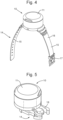
- Fig. 4 shows an example in which the mounting arrangement 14 is a strap or sling 15 having two strap portions 16 which may be connected together by a buckle 17 (or other connector such as a clasp) to mount the strap 15 around an object.
- the mounting arrangement 14 is a strap or sling 15 having two strap portions 16 which may be connected together by a buckle 17 (or other connector such as a clasp) to mount the strap 15 around an object.
- Fig. 5 shows an example in which the mounting arrangement 14 is a mounting clip 18 which may be clipped into a receiving element (not shown) which is mounted to the rotatable element 5.
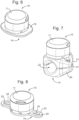
- Fig. 6 shows an example in which the mounting arrangement 14 is a base 19 having an adhesive provided on the lower surface (not shown) allowing the sensor unit 10 to be adhesively mounted to the rotatable element 5.
- Fig. 7 shows an example in which the mounting arrangement 14 is a clamp 20 comprising two clamp portions 21 having a central aperture 22.
- the clamp portions 21 may be clamped to an element, for example a pipe, arranged in the aperture 21.
- Fig. 8 shows an example in which the mounting arrangement 14 is a base 23 having flanges 24 provided with apertures 25 for receiving standard fasteners, for example a bolt, screw, rivet, or nail, by which the sensor unit 10 may be mounted to a rotatable element.
- standard fasteners for example a bolt, screw, rivet, or nail
- the sensor unit 20 may be mounted on a wide range of types rotatable elements 2, without limitation to those illustrated in Figs. 1 and 2 .
- Non-limitative examples of rotatable elements 5 on which the sensor unit 10 may be mounted include:
- Figs. 9 and 10 illustrate two examples of a sensor unit 10 mounted on a hand wheel 26 which is used to operate a valve 27.
- the sensor unit 10 has a mounting arrangement 14 that is a clamp 20 of the type shown in Fig. 7 .
- the sensor unit 10 has a mounting arrangement 14 that is a base 23 of the type shown in Fig. 8 .
- the illustrated valve 27 is a butterfly valve, but in general the valve 27 could be any type of valve controlled by a hand wheel, for example a ball valve, gate valve, globe valve, etc.
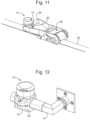
- Fig. 11 illustrates a sensor unit 10 mounted on the handle 28 of a ratchet mechanism 29 of a ratchet strap 30.
- the sensor unit 10 has a mounting arrangement 14 that is a clamp 20 of the type shown in Fig. 7 .
- Fig. 12 illustrates a sensor unit 10 mounted on a door handle 31.
- the sensor unit 10 has a mounting arrangement 14 that is a clamp 20 of the type shown in Fig. 7 .
- the sensor unit 10 could be mounted on other handles such as a window or hatch handle.
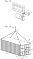
- Fig. 13 illustrates a sensor unit 10 mounted on a crane arm 32.
- the sensor unit 10 has a mounting arrangement 14 that is a base 23 of the type shown in Fig. 8 .
- Fig. 14 illustrates plural sensor units 10 mounted on a shipping container 33 that is the load of a crane (not shown). Some of the sensor units 10 are mounted to rotatable elements of the shipping container 33 itself, in particular to a hinge 34, a handle 35, and a lock 36. Some of the sensor units 10 are mounted to the crane ropes or slings 37. Similarly, sensor units 10 could be mounted to any other load of crane. The orientation of the crane ropes 37 and the container 33 itself changes as the crane is operated and such rotation may be monitored by the sensor unit 10.
- Fig. 15 illustrates a sensor unit 10 mounted on a pipe 38 that may contain a fluid 39 that flows along the pipe 38.
- the pipe 38 may be of any size and type, and the fluid 39 may be of any type, for example a fluid in oil and gas extraction or production, which may be an emulsion.
- the orientation of the pipe 38 may change in use, and such rotation may be monitored by the sensor unit 10.
- Fig. 16 illustrates plural sensor units 10 mounted on a container 40 containing fluids 41, which in this non-limitative example comprises two components 42 and 43 which are immiscible.
- the container 40 may be any type of container, and the fluids 41 may be of any type.
- the container 40 may be a container used in oil and gas extraction, production or storage.
- the container 40 may be a separator.
- Fig. 17 illustrates a sensor unit 10 mounted on a latch 44 of an assembly 2 which is a fingerboard latch assembly.
- Plural such assemblies may be mounted along a fingerboard 101 to retain a tubular of any type, for example a drill pipe, drill collar or casing.
- the latch 44 is rotatably mounted on a bracket 45 and is an example of an assembly of the first type shown in Fig. 1 .
- the latch 44 is actuated by a pneumatic cylinder 46.
- the sensor unit 10 is mounted to the latch 44, in this example within an aperture 47 in the latch 44, the sensor unit 10 being retained therein by a retaining member 48 that engages with the sensor unit 10. Further details of possible configurations of the housing 11 to allow mounting on a latch 105 are disclosed in WO2018/007804 to which reference is made.
- the housing 11 houses a sensor circuit 50 as will now be described.
- the construction of the housing 11 is as follows.
- the housing 11 comprises a base 76 and a cap 79 that is fixed over the base 76.
- the base 76 and the cap 79 form an enclosure 78 in which the electronic components of the sensor circuit 50 are contained.
- the enclosure 78 seals the electronic components and has no external electrical connections which could compromise the integrity.
- the enclosure 78 is resistant to fluids and ultraviolet light to suitable standards, for example the IP67 standard.
- the enclosure 78 contains a battery 77 that acts as a power source for the sensor circuit 50.
- a circuit board 80 on which the sensor circuit 50 is formed is provided above the battery 77.
- a capacitor 81 is fixed to the circuit board 80 adjacent the battery 77, and a first spacer 82 beside the capacitor 81 spaces the circuit board 80 from the battery 77.
- a first light emitter 83 which is typically a light emitting diode, is arranged at the bottom of the housing 11, beneath the battery 77, spaced from the battery 77 by a second spacer 84.
- the first light emitter 83 is a light source that may be used as described further below.
- a flexible circuit 85 as best shown in Fig. 19 , connects the first light emitter 83 to the circuit board 80.
- a second light emitter 87 which is typically a light emitting diode, is arranged at the top of the housing 11, on top of the circuit board 80.
- the cap 79 is sufficiently thin or transparent thin to allow output of light so that the second light emitter 87 forms an additional or alternative light source from the first light emitter 83.
- the housing 11 may be fabricated from any suitable material, typically a non-metallic material.
- the housing 11 may be made from a tough, durable material to withstand shock, vibration, temperature extremes, ice, direct sunlight, UV degradation and washing with a high-pressure jet of water at over 200 Psi.
- the housing 11 may be made from any suitable material. Suitable materials include, without limitation: carbon fibre; fibreglass (glass reinforced plastic); a fibrous material such as Kevlar; a plastic, for example Polyether ether ketone (PEEK) or any type of Polyaryletherketone (PAEK); an elastomer, for example a rubber; or other engineering thermoplastics.
- the material may be a reinforced material, for example PEEK reinforced with carbon fibre, or fibreglass.
- the material may be a composite.
- the housing 11 may also incorporate at least one non-metallic liner.
- a liner may provide compressive engagement between the sensor unit 10 and it's mounting to accommodate tolerances for the dimensions of the rotatable element 5 which can be broad, thereby increasing friction and integrity.
- Such a liner may provide, and/or sealing, for example to keep out oils and debris.
- Such a liner may be an O-ring or a sleeve.
- the housing 11 comprises liners in the form of an O-ring.
- the material of the liner may be of a type known to be suitable for use as a lining in oil and gas applications.
- Suitable materials for the non-metallic lining can include: polyisoprene, styrene butadiene rubber, ethylene propylene diene monomer rubber, polychloroprene rubber, chlorosulphonated polyethylene rubber, 'Viton', nitrile butadiene rubber. This list is non-limitative and other elastomers could be used.
- the material may also be a mixture of these and/or other materials.
- a battery 77 is provided as a power source. More generally the battery 77 may be replaced by any type of standalone power source known in the art that is capable of providing power to the sensor unit 10 may be provided.
- the power source may comprise a battery, solar cell, fuel cell, supercapacitor or capacitor.
- the power source may optionally comprise an energy harvesting device that is configured to harvest energy from the assembly 2.
- the power source may be configured to harvest energy from the motion, shock or vibration of the rotatable element 5.
- the power source may be provided integral with the sensor unit 10, or removably attached to the sensor unit 10. A sensor unit 10 that is easily maintained may thus be provided.
- the battery 77 has long life characteristics.
- the battery 77 is ideally compact in format to fit within the sensor unit 10.
- the battery 77 ideally will have sufficient capacity to power the sensor circuit 50 for tens of thousands of rotational cycles over several years (e.g. 20,000 cycles and five years).
- the battery 77 may be a Lithium Thionyl Chloride battery that has been selected and configured to last the lifetime of the equipment.
- the sensor circuit 50 may be arranged as shown in Fig. 20 as will now be described.
- the sensor circuit 50 includes an orientation sensor 18 (or plural orientation sensors), a processor 52, a wireless communication interface 57, the first light emitter 83 and/or second light emitter 87, which act as light sources, and a power source 56, that may be the battery 77 in the above description or any other known type of power source as discussed above.
- the orientation sensor 18 takes measurements that are dependent on the orientation of the sensor unit 10.
- the orientation sensor 18 may be any type of sensor suitable for detecting the orientation of the rotatable element 5.
- the sensor 18 may preferably be a low power sensor such as a MEMS sensor, which may be for example configured as an inclinometer, accelerometer, magnetometer or gyroscope.
- MEMS sensor such as a MEMS sensor
- Examples of alternative types of sensor that could be used include: tilt ball sensor; infrared; laser; optical, digital imaging, acoustic; capacitive; magnetic, antenna polarisation or Hall Effect sensors.
- the sensor 10 may be of a type that is relatively simple and of low power compared to a sensor mounted on the mounting element 3 that indirectly senses the rotatable element 5.
- the sensor unit 10 is inexpensive and capable of being run where the power source 56 has limited capacity, for example being a battery.
- the processor 52 is supplied with the measurements from the orientation sensor 18 and processes them.
- the processor 52 derives, from the measurements, a rotational position signal representing the rotational position of the rotatable element 5 with respect to the mounting element 3. In general terms, this is possible because the sensor unit 10 is mounted in the rotatable element 5 and so the orientation of the sensor unit 10 is indicative of the orientation of the rotatable element 5.
- the rotational position is uniquely identified by the orientation indicated by the measurements from the accelerometer 53.
- the rotational position may be derived from the orientation indicated by the measurements from the accelerometer 53 to provide the rotational position within a turn and from the history of the orientation indicated by the measurements from the accelerometer 53 to derive the rotational position as between different turns, for example by determining and counting the number of turns indicated by the changing orientation.
- the rotational position signal may represent the value of the present rotational position of the rotatable element 5 across its range of movement with respect to the mounting element 3.
- the rotational position signal may simply represent that the present rotational position of the rotatable element 5 is an open state corresponding to one limit of the range of rotation, a closed state corresponding to the other limit of the range of rotation, or an intermediate state corresponding to any position intermediate the limits of the range of rotation.
- the open state and the closed state may be taken to correspond to the rotatable element 5 being within a predetermined range of angles, for example 6 degrees, of the respective limits of the range of rotation.
- the open and closed state may be derived by applying a suitable threshold condition on the rotational position indicated by the successive measurements.
- a rotational position signal that represents the value of the rotational position of the rotatable element 5 may or may not be explicitly derived, but the threshold condition is related to the measurements on the basis of similar geometrical calculation.
- the wireless communication interface 57 provides wireless communication and may be a radio communication interface arranged to transmit signals using radio frequency electromagnetic waves.
- a frequency may be selected that has a wavelength that is suitable for the field of use. The frequency selected should not interfere with marine communications equipment, Optionally, the frequency selected may be between 2 and 3 GHz.
- the wireless communication interface 57 may employ any other form of wireless communication for communicating the orientation signal, for example acoustic, microwave, ultrasonic or optical communication.
- the wireless communication interface 57 may be unidirectional and merely transmit information from the sensor unit 10, or may be bidirectional and transmit and receive information.
- the wireless communication interface 57 may implement any suitable transmission protocol.
- the wireless communication interface 57 is used to wirelessly communicate the rotational position signal to a monitoring system 65 described further below, under the control of the processor 52.
- the processor may associate metadata with the rotational position signal. Such associated metadata may be wirelessly communicated with the rotational position signal.
- the metadata may be generated by the sensor units 10 monitoring rotatable elements 5 throughout an array of assemblies 2.
- the metadata may include includes time information, for example date and time.
- the metadata may include rotatable element characteristics such as sensor identity, rotatable element identity, number of rotatable element cycles, count of rotatable element being in open position, count of rotatable element being in closed position, rotatable element speed, rotatable element acceleration, sensor battery level, orientation sensor signal level, signal polarisation, antenna signal strength, sensor location, or self-diagnostic information, for example relating shocks or vibration or recorded anomalies or warnings logged.
- the sensor circuit 50 may include a geolocation unit 58 arranged to detect the location of the sensor unit 50, for example a global position system (GPS) unit.
- the metadata may include the location detected by the geolocation unit 58. This can be useful to indicate the location of plural sensor units 10 arranged across an array of assemblies 2.
- the sensor circuit 50 may include a further sensor 59, which may in general be any type of sensor that is used to monitor another characteristic of the rotatable element 5 to be monitored in parallel with its rotational position. More than one such further sensor 59 may be included.
- the further sensor 59 may be any of the following:
- Such a further sensor 59 may provide a combined condition monitoring device that operates wirelessly in harsh environments such as a floating platform used for marine transportation, hydrocarbon production, floating production and storage offshore (FPSO), drilling or exploration;
- FPSO floating production and storage offshore
- Such a further sensor 59 may provide monitoring of location, condition, integrity, security and orientation of cargo, e.g. ISO containers, retaining brackets, seals and doors.
- cargo e.g. ISO containers, retaining brackets, seals and doors.
- Such a further sensor 59 may monitoring of fluids including composition of fluids (oil, solids and water), pH, conductivity, salinity, electro-magnetism, magnetic resonance, viscosity, density and surface tension, e.g. monitoring of fluid level (which may be necessary when accurately measuring composition) in tanks, separators, pipes, conduits, manifolds, shaker header boxes, channels or other vessels with respect to orientation of a floating platform 11.
- fluids including composition of fluids (oil, solids and water), pH, conductivity, salinity, electro-magnetism, magnetic resonance, viscosity, density and surface tension
- the further sensor 59 may monitor the level 44 or composition of the fluid 39, which may vary with the orientation of the pipe 38.
- the further sensor 59 may monitor the level of a surface 45 and/or an interface 46, which may vary with the orientation of the container 40. This may be important, for example, in storage and production of oil and water.
- the sensor circuit 50 system may include other electronics and processing capability, including memory for storing software, firmware, data and records.
- any other method of communicating the rotational position signal may be used.
- the first light emitter 83 and/or second light emitter 87 act as one or more light sources as will now be described.
- the provisional of light sources is optional, but the light sources may be provided, in addition to, or as an alternative to, the use of the wireless communication interface 57 for communication of the rotational position signal and other information, such as the metadata.
- first light emitter 83 and/or second light emitter 87 may be also used, as an alternative to the first light emitter 83 and/or second light emitter 87.
- the light sources may be provided in any location in the sensor unit 10 that is visible or has a line of sight in use
- the sensor unit 10 may be mounted so that the light sources are directed downwards in the case of assemblies 2 that are mounted in a high location, so that they are visible from below. It also keeps them cleaner, reducing the risk of obscuring the output light.
- the light sources may emit light in any suitable wavelength band, for example infrared, visible or ultraviolet.
- the light output by the one or more light sources is modulated in accordance with the orientation of the rotatable element 5 sensed by the sensor 18, under the control of the processor 52.
- a reliable indication of the orientation of the rotatable element 5 may be provided.
- Modulating a light source to represent the orientation of the rotatable element 5 allows for a wireless sensor unit to be provided that is suitable for use in remote locations without the need to make an electrical connection.
- the light sources may provide instant indication of position, security or condition, of the rotatable element or monitoring device.
- the modulation of the light sources may be implemented in a number of ways, some non-limitative examples being as follows.
- the light sources may be in an on or off state corresponding to two different rotational positions of the rotatable element 5, e.g. open and closed positions.
- a lit light source may identify that the rotatable element 5 is in a closed position
- an unlit light source may indicate that the rotatable element 5 is in an open position.
- the modulation may be a change in illumination timings (e.g. flashing rate) of the light sources.
- illumination timings e.g. flashing rate
- two (or optionally more) illumination timings may indicate two (or optionally more) rotational positions of the rotatable element 5, for example a closed position and an open position (and optionally one or more other intermediate rotational positions).
- the output of the light sources is flashed on and off, but modulated by varying the period. This is advantageous because power is saved compared to a continuous output of light.
- the time for which the light source is flashed on in each period, in each of the different illumination timings may be sufficiently long to be detected by a human observer or camera system, depending on which is used to monitor the output.
- the time for which light source is flashed on is sufficiently long to be visible taking account of the persistence of vision, for example at least 5ms, preferably at least 8ms, at least 10ms, or at least 20ms.
- the time for which light source is flashed on is sufficiently long to be reliably detected thereby, taking account of the camera and processing technology used.
- the time for which light source is flashed on may the same for each modulation, i.e. irrespective of the length of the period.
- modulation may be achieved by changing the time for which light is not output (i.e. for which the light source is off).
- the time for which light is not output may be 48ms for one orientation of the rotatable element 5 and may be 480ms to indicate another orientation of the rotatable element 5.
- the modulation may be a change in the colour of light output by the light sources.
- two (or optionally more) colours may indicate two (or optionally more) rotational positions of the rotatable element 5, for example a closed position and an open position (and optionally one or more other intermediate rotational positions).
- the modulation of the light output by the light sources may be monitored by a person or remotely monitored via a camera system such as closed circuit television. Image processing may be used to provide automated monitoring.
- the modulation of the light output by the light sources 10 may also represent information in addition to the sensed rotational position of the rotatable element 5.
- modulation as between the light sources of different assemblies 2 may additionally represent the spatial location of the rotatable element 5. This is advantageous when sensor units 10 are mounted on plural assemblies 2 of an array, as the modulation may then indicate the rotational position and the spatial location of the rotatable elements 5 within the array.
- light sources of different sensor units 10 may output light of different colours in order to provide differentiation between the spatial locations of the assemblies 2 to which the sensor units 10 are mounted.
- the modulation may indicate maintenance information, for example information about the motion of the rotatable element 5 that is indicative of wear, such as an excessive time for movement between open and closed positions, or a significant bounce of the rotatable element 5 on reaching the open or closed position.
- orientation of the rotatable element 5 and the additional information may be represented by different types of modulation, for example representing orientation of the rotatable element 5 by modulation of illumination timing and indicating maintenance information by modulation of colour, for example green light indicating a positive condition and red light indicating the need for maintenance.
- the orientation sensor 18 may be implemented by an accelerometer 53 in an accelerometer chip 51 that is illustrated in Fig. 21 .
- the accelerometer chip 51 is arranged as follows.
- the accelerometer 53 may be a microelectromechanical systems (MEMS) device. Such a type of device is advantageously reliable and of low cost.
- MEMS microelectromechanical systems
- the accelerometer chip 51 further includes a low-pass filter 60, and ADC (analog-to-digital converter 61 and a buffer 54 and an accelerometer processing unit 55.
- the accelerometer processing unit 55 performs basic control functions for the accelerometer chip 51.
- the low-pass filter 60 filters the measurements output from the accelerometer 53 which is the orientation sensor in this implementation. As the measurements are analog, in this example the low-pass filter 60 is an analog device.
- the filtered measurements are supplied from the low-pass filter 60 to the ADC 61 which analog-to-digital converts the filtered measurements.
- the resultant digital measurements are supplied to the buffer 54, which buffers measurements before supply to the processor 42, as described below.
- a low-pass filter 60 is not commonplace in an accelerometer chip, but use of the accelerometer chip 51 that does include a low-pass filter 60 is advantageous in the present application for the following reasons.
- an accelerometer is suitable to detect the orientation of the rotatable element 5 reliably in benign conditions by detecting the direction of acceleration due to the earth's gravitational field.
- the change in the forces as the rotatable element 5 moves between the two positions shown in Figs. 1 and 2 i.e the open position O and the closed position C in Fig. 1 and the first position V and the second position H in Fig. 2
- the change in the forces as the rotatable element 5 moves between the two positions shown in Figs. 1 and 2 i.e the open position O and the closed position C in Fig. 1 and the first position V and the second position H in Fig. 2
- vibration which may be up to 4g
- shock of collisions or impacts which may be tens of g
- vibrational forces may be less than 0.5 g at, say, 3Hz, but around 4g at, say, 25-100Hz.
- Typical low cost accelerometers for example using MEMS technology, have a relatively high natural frequency, typically of the order of 1kHz. Such accelerometers will respond to the high frequency vibration. In many applications, that is an advantage. As a result, such accelerometers may be designed to have a sampling rate of greater than double the natural frequency to avoid the risk of aliasing.
- accelerometers with a lower natural frequency are less easily available, particularly as small size, low cost, low power devices.
- the provision of the low-pass filter 60 allows for removal of the signal from the forces on the rotatable element 5 arising from vibration and shock of collisions or impacts, without the need to low-pass filter the measurements in the processor 42.
- the low-pass filter 60 before the ADC 61, the high frequency noise can be removed with a limited power consumption in the ADC 61.
- the arrangement of the accelerometer chip 51 allows a robust system to be designed with a reduced ADC sampling frequency.
- the cut-off frequency (which may be defined for example as a 3 dB corner boundary in the frequency response at which the signal begins to be reduced) of the low-pass filter 60 may be chosen to attentuate at least some of the noise while passing signal representing the motion of the rotatable element 5 with a response time that is sufficiently short to provide useful monitoring.
- the cut-off frequency may be at most 50Hz, preferably at most 25Hz.
- a cut-off frequency of 12.5 Hz is chosen. Cut-off frequencies of such orders are low enough to reduce power consumption while still providing a useful measurement signal. A lower value down to 1Hz may provide further benefits in reducing the impact of vibration, but would introduce a small delay.
- the low-pass filter 60 may be non linear such that the effect of high shock loads on the accelerometer 53 from pipes is reduced. For example, measurements may be gathered for 200ms, that is 10 samples at 50Hz. The two largest and two smallest values may rejected and the remaining 6 samples averaged. This further helps remove the transient from pipe shocks on the rotatable element 5.
- the accelerometer chip 51 is chosen to have a relatively low power consumption.
- the accelerometer chip 51 may be an ADXL363 or alternatively an ADXL362, both commercially available from Analog Devices TM .
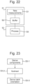
- the sensor circuit 50 operates as shown in Fig. 22 , wherein steps S1 and S2 are performed in the accelerometer chip 51 and step S3 is performed in the processor 42.
- step S1 the accelerometer 53 takes measurements representing acceleration relative to an inertial frame along two axes perpendicular to the rotational axis of the rotatable element 5. These measurements are therefore dependent on the orientation of the sensor unit 10 as the rotatable element 5 rotates.
- Figs. 1 and 2 wherein the two axes X and Z along which measurements of acceleration are taken by the accelerometer 42 are shown for the two positions illustrated therein (i.e. the open position O and the closed position C in Fig. 1 and the first position V and the second position H in Fig. 2 ).
- the axes X and Z rotate with the rotatable element 5.
- the acceleration along the axis X is zero and the acceleration along the axis Z is g, the acceleration due to gravity
- the acceleration along the axis X is g and the acceleration along the axis Z is zero.
- the accelerations along the axes X and Z vary as the orientation varies with respect to gravity. Consequently, the measurements of acceleration along the axes X and Z are represent the orientation of the sensor unit 5.
- the measurements of acceleration along both the axes X and Z are used in combination by the processor 42 to derive the orientation of the sensor unit 10 using a simple geometrical calculation (subject to the movement of the mounting element 3 as discussed below).
- a measurement of acceleration along a single one of the axes X and Z could alternatively be used to derive the orientation of the sensor unit 10, but this is not preferred as it is less accurate.
- the accelerometer 53 therefore functions as an orientation sensor.
- the accelerometer 53 could be replaced by any suitable alternative form of orientation sensor, for example a gyroscope or magnetometer.
- an accelerometer 53 provides the advantage of having a relatively lower power consumption, which is important in the present application as it may be burdensome to change the power source 56, given the inaccessible location of the sensor unit 10 in normal use on the assembly 2.
- step S2 the buffer 54 buffers a series of recent measurements taken by the accelerometer 53 over a predetermined period of time and supplied to the buffer 54 through the low-pass filter 60 and the ADC 61.
- the processor 42 processes the measurements in steps S3 as follows.
- step S3 a rotational position signal which represents the rotational position of the rotatable element 5 with respect to the mounting element 3 is derived from the measurements. If the mounting element 3 were stationary, this could be derived in a straightforward manner, because the measurements represent the orientation of the sensor unit 10, and hence the orientation of the rotatable element 5, relative to the gravitational field of the earth as described above. However, as the floating platform 11 on which the mounting element 3 is mounted moves under the influence of waves, the motion of the floating platform 11 and hence the mounting element 3 also affects the measurements.
- the first effect is that the orientation of the mounting element 3 itself changes as the floating platform 11 pitches or rolls with the waves in the same plane as the rotation of the rotatable element 5. Typically, such pitching or rolling may be up to +/- 15 degrees.
- the change in orientation of the mounting element 3 changes the orientation of the rotatable element 5 when it is stationary with respect to the mounting element 3. This changes the measurements of acceleration along the axes X and Y, in just the same way as change in orientation of the rotatable element 5 with respect to the mounting element 3. So an individual measurement cannot provide indicate whether the derived orientation arises from the orientation of the rotatable element 5 with respect to the mounting element 3 or the mounting element 3 with respect to the earth's gravitational field.
- the second effect is that the actual motion of the floating platform 11 creates accelerations along the axes X and Y in addition to those caused by change of orientation with respect to the earth's magnetic field. Accelerations may be caused by pitch and roll of the floating platform 11. These accelerations are magnified by the height at which the assembly 2 is mounted. Typically, this height is many tens of meters high, so the magnification is quite large. Such accelerations caused by pitch and roll will affect the acceleration along the axes X and Y in different ways depending on the orientation of the rotatable element 5. For example, as pitch and roll causes motion along an arc that is horizontal with respect the assembly 2 as shown in Figs.
- the accelerations are predominantly along the axis X when the rotatable element 5 is in the open position O and along the axis Z when the rotatable element 5 is in the closed position. Accelerations may also be caused by heave, surge and sway of the floating platform 11, but these accelerations are limited by the inertia of the floating platform 11.
- the predetermined period of time for which measurements are buffered is chosen to be sufficiently long to characterise wave motion of the longest period likely to be encountered in practice. This may depend on where the sensor unit 10 is deployed geographically. Typically, the predetermined period of time is at least 20 seconds, preferably at least 30 seconds.
- Step S3 is performed to derive the rotational position signal, making the correction to compensate for the effect of the motion of the mounting element 3 on the measurements, as shown in Fig. 23 and now described
- step S3-1 components of each successive measurement estimated to be caused by the motion of the mounting element 3 are derived from the overall series of measurements buffered in the buffer 54.
- the change in the measurements over the predetermined period of time may be taken to derive from the motion of the mounting element 5.
- the component of each successive measurement may be estimated from the overall series of measurements previously buffered in the buffer 54.
- Step S3-1 may be performed on the overall series of measurements buffered in the buffer 54 by any suitable analysis process, for example a filtering process.
- any suitable analysis process for example a filtering process.
- the overall series of measurements may be analysed to derive the amplitude, frequency and phase of the fundamental frequency component of the series of measurements, which in turn may be used to derive the component of each successive measurement estimated to be caused by the motion of the mounting element 3. More complicated analysis processes may take account of harmonics of the series of measurements.
- step S3-2 the components of each successive measurement derived in step S3-1 is subtracted from the corresponding successive measurements themselves. This results in the derivation of corrected measurements.
- step S3-3 the corrected measurements derived in step S3-2 are used to derive a rotational position signal.
- the derived rotational position signal represents the rotational position of the rotatable element 5 with respect to the mounting element 3, rather than the rotational position of the rotatable element 5 with respect to the earth's gravitational field.
- the rotational position signal represents the value of the present rotational position of the rotatable element 5 across its range of movement with respect to the mounting element 3
- the value of the present rotational position may be derived from the corrected measurements using a simple geometrical calculation, of the type discussed above.
- the open and closed state may be derived by applying a suitable threshold condition on the corrected measurements.
- the rotational position signal derived by the processor 42 is supplied to the wireless communication interface 57 which communicates the rotational position signal wirelessly to the monitoring system 65.
- the correction is applied to the successive measurements themselves.
- the correction may be applied by first deriving an absolute rotational position signal representing the absolute rotational position of the rotatable element 5 from the successive measurements, and then making a correction to the absolute rotational position signal that compensates for the effect of the motion of mounting element 3 on the measurements on the basis of the overall series of measurements buffered in the buffer 54.
- the correction may be made by deriving an estimated rotational position signal representing the estimated orientation of the mounting element 3 from the overall series of overall series of measurements buffered in the buffer 54, and then subtracting the estimated rotational position signal from the absolute rotational position signal.
- the corrected absolute rotational position signal is therefore the rotational position signal representing the orientation of the rotatable element 5 with respect to the mounting element 3.
- Techniques may be applied to reduce the power consumption of the sensor circuit 50.
- One possible technique for reducing power consumption uses a processor 42 that has an active state in which processing can be performed and an inactive state in which processing cannot be performed, where the processor 42 consumes less power in the inactive state than in the active state.
- the buffer 54 is arranged to continually buffer the series of recent measurements, but the processor 42 is initially in the inactive state in which it does not perform step S3.
- the accelerometer processing unit 55 monitors the buffered series of recent measurements and supplies an interrupt signal to the processor 42 when the series of recent measurements exceed a threshold condition.
- This threshold condition corresponds to a significant degree of motion, that might correspond to change in orientation of the rotatable element 5, albeit that the accelerometer processing unit 55 does not process the measurements and so cannot determine whether the motion corresponds to change in orientation of the rotatable element 5 or change in orientation of the mounting element 3.
- the processor 42 which is in the inactive state prior to receipt of the interrupt signal, enters the active state and performs step S3 to derive the rotational position signal upon receipt of the interrupt signal.
- the processor 42 which has a relatively high power consumption only perform step S3 to process the measurements when the series of recent measurements exceed the threshold condition which might correspond to movement of the rotatable element 5. Otherwise, when the series of recent measurements do not exceed the threshold condition, no power is consumed by the processor 42. While the processor 42 is in that inactive state, the power consumption by the accelerometer chip 51 is relatively low.
- the processor 42 may remain in the active state performing step S3 for a predetermined period of time, or continuously, after the rotatable element 5 has changed state into the open state or the closed state, so as to detect a subsequent change.
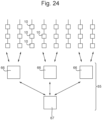
- FIG. 24 A non-limitative example of the monitoring system 65 is shown in Fig. 24 and will now be described.
- the monitoring system 65 comprises plural wireless communication transceivers 66 each arranged to receive rotational position signals wirelessly from a plurality of the sensor units 10.
- the wireless communication transceivers 66 may be implemented by conventional wireless networking equipment, for example as a router/concentrator.
- the wireless communication transceivers 66 act as gateways and are distributed to provide overall coverage of the assemblies 2 in the array.
- the wireless communication transceivers 66 may be located at valve cabinets, to maximise reception and signal coverage.
- the wireless communication transceivers 66 may be located at four locations, east, west, north and south of an array of assemblies 2.
- the wireless communication transceivers 66 may include plural antennae arranged with a spatial diversity for the purpose of maximising signal strength irrespective of the polarisation of the received signals.
- the monitoring system 65 also comprises a central unit 67 with which the wireless communication transceivers 66 are further arranged to communicate wirelessly for relaying the rotational position signals and other information from the wireless communication transceivers 66 to the central unit 67.
- the central unit 67 performs the overall monitoring and processing of the rotational position signals and other information, and may be implemented by any suitable equipment including a wireless communication interface.
- the central unit 67 may include a conventional computer for processing the received information.
- the central unit 67 is located at a suitable location to communicate with all the wireless communication transceivers 66.
- the central unit 67 may be located at, or near, the drillers' cabin and/or the Local Equipment Room (LER).
- LER Local Equipment Room
- This topology for the monitoring system 65 provides advantages of wide coverage and reliability, particularly if the wireless communication transceivers 66 have overlapping coverage.
- the monitoring system 65 shown in Fig. 24 is not limitative, and in general may have any suitable configuration.
- the monitoring system 65 receives rotational position signals and other information from sensor units 10 on each assembly 2 in an array of assemblies, for simultaneously monitoring of all the assemblies 2.
- the monitoring system 65 described above receives information from the sensor units 10 primarily by wireless communication from the wireless communication interfaces 57. Alternatively or additionally, the monitoring system 65 may monitor the light sources, for example using cameras.
- the monitoring system 65 provides an indication of the orientations of the rotatable elements 5 to a user, for example on a display or audibly.
- the monitoring system 65 may provide a warning when the orientation of any rotatable elements 5 is unexpected and/or in a dangerous state.
- the monitoring system 65 may also monitor the other information transmitted from the sensor units 10. Such information representing characteristics of the rotatable element 5 may be may be logged and analysed to identify rotatable elements 5 that are not performing to specification, or may be in need of maintenance or replacement. This information may be analysed for condition-based monitoring the rotatable elements 5 to minimise downtime and, by planning maintenance based on likelihood of failure, maximise availability and operational efficiency.
- the data logs and metadata may be presented to manufacturers, suppliers, customers or regulators to validate equipment warranty, indicate safety performance and to demonstrate compliance with best practice and compliance with regulations.
- the monitoring system 65 may be used to monitor and track information from the geolocation 58 and/or the further sensor 59 in combination with the rotational position.
- monitoring performed by the monitoring system are as follows.
- the monitoring system 65 may be used to track condition and integrity of containers, including shipping containers, for example by mounting sensing units 10 on a container 33 as shown in Fig. 14 .
- the monitoring system 65 may compare rotational position signals from different sensor units 10 and to detect anomalies therein, for example an unexpected relationship between the orientation of particular rotatable elements 5.
- a load which in this example is the container 33
- further sensors 59 that are load cells and/or strain gauges
- comparison of orientation from plural sensor units 10 or comparison of orientation with other parameters such as strain and/or load
- further sensors 59 that are load cells could be included in sensor units 10 to detect anomalous loads or shifting of loads that are provided on pallets, baskets or cradles 72.
- the monitoring system 65 may monitor the level 44 or composition of a fluid 39, as sensed by a further sensor 59, with respect to pipe orientation.
- the monitoring system 65 may monitor the level of a surface 45 and/or an interface 46, as sensed by a further sensor 59, with respect to orientation which could be important in storage and production of oil and water for example, or may monitor the output of a further sensor 59 such as a load cell and use that to compute mass or volume corrected with respect to rotational position.
Landscapes
- Physics & Mathematics (AREA)
- Engineering & Computer Science (AREA)
- General Physics & Mathematics (AREA)
- Radar, Positioning & Navigation (AREA)
- Remote Sensing (AREA)
- Arrangements For Transmission Of Measured Signals (AREA)
- Ultra Sonic Daignosis Equipment (AREA)
- Rotational Drive Of Disk (AREA)
- Measuring Fluid Pressure (AREA)
Description
- The present invention relates to a sensor for a rotatable element.
- In many applications it is desirable to sense the orientation of a rotatable element that is rotatable, for example to provide safety during operation of the rotatable element. In the event of a mechanical failure or a failure in an actuation system for the rotatable element, which may be for example pneumatic, then the rotatable element might not be in the expected position which may create safety issues.
- There are various types of sensing technology that are used to sense the rotation of a rotatable element that rotates continuously. However, such sensing technology generally relies on periodic measurements that result from the continuous motion, and as such is not directly applicable to a rotatable element that is rotatable within a limited range of rotation or where changes in orientation typically occur sporadically.
- The present invention tackles a potential difficulty when the rotatable element is mounted on a platform that is itself movable, such as a floating platform or a moving vehicle or swaying container, for example a floating platform as may be used for offshore drilling or exploration. Notionally, if a sensor unit were provided with an orientation sensor to detect the absolute orientation of the rotatable element, then the measurements taken by the are affected by the movement of the platform, not just the orientation (rotational position) of the rotatable element with respect to platform. This can lead to difficulties in sensing the orientation of the rotatable element, and potentially to erroneous sensing.
- According to the present invention, there is provided a sensor unit that is mountable on a rotatable element on a platform that is itself movable at a slower rate than the rotational motion of the rotatable element with respect to the platform, the sensor unit comprising: an orientation sensor arranged to take measurements that are dependent on the absolute orientation of the sensor unit; and a processor arranged to derive a rotational position signal representing the rotational position of the rotatable element with respect to the platform from the measurements; and a buffer arranged to buffer a series of recent measurements taken by the orientation sensor over a predetermined period of time, wherein the processor is arranged to derive the rotational position signal making a correction to compensate for the effect of the motion of the platform on the measurements on the basis of the overall series of measurements buffered in the buffer.
- The sensor unit is mounted on the rotatable element and includes an orientation sensor that takes measurements that are dependent on the orientation of the sensor unit. In principle, such measurements allow for a simple and reliable detection of the rotational position of the rotatable element. In particular, it allows the use of a type of sensor that is simpler than a typical external sensor with sufficiently reliable sensing. Similarly, the sensor unit may have a relatively low power consumption permitting use of an internal power source such as a battery and being capable of being run for extended periods of time.
- The potential difficulty when the rotatable element is mounted on a platform that is itself movable, as discussed above, issue is dealt with by buffering a series of recent measurements taken over a predetermined period of time in a buffer and using the overall buffered series of measurements to make a correction to compensate for the effect of the motion of the platform on the measurements.
- It has been appreciated that the motion of the platform can be characterised by the overall series of measurements buffered in the buffer over the predetermined period of time, despite the fact that the sensor unit is mounted on the rotatable element. This is because the platform moves with the platform, and so this motion typically occurs at a relatively slow rate compared to the movement of the rotatable element with respect to the platform, for example being caused primarily by waves in the case of a floating platform. Thus, the overall series of measurements taken over the predetermined period of time characterise the motion of the platform, and can be used to make a correction that compensates for that motion when deriving the rotational position signal from the measurements.
- The processor may be further arranged to associate metadata with the rotational position signal. Such metadata may include one of more of time information; sensor identity, rotatable element identity, number of rotatable element cycles, count of rotatable element being in open position, count of rotatable element being in closed position, rotatable element speed, rotatable element acceleration, rotatable element angle, battery level, orientation sensor signal level; signal polarisation, antennae signal strength, sensor location, signal triangulation, and location, which may be detected by a geolocation unit in the sensor unit.
- The sensor unit may further comprise a wireless communication interface arranged to wirelessly communicate the rotational position signal. This allows for remote location of the sensor unit, without the need to make a wired connection. That reduces installation difficulties and avoids risks associated with damage to the wires.
- The sensor unit may further comprise a light source and be arranged to modulate the light output by the light source to represent the orientation of the rotatable element. This allows for a wireless sensor unit to be provided that is suitable for use in remote locations without the need to make an electrical connection, as the output of the light source may be monitored.
- Further according to the present invention, there is provided a method corresponding to the operation of the sensor unit.
- Embodiments of the present invention will now be described by way of non-limitative example with reference to the accompanying drawings, of which
-
Fig. 1 is a side view of a first type of assembly including a rotatable element and a sensor element; -
Fig. 2 is a side view of a second type of assembly including a rotatable element and a sensor element; -
Fig. 3 is a schematic view of a floating platform on which the assembly may be mounted; -
Figs. 4 to 8 are perspective views of sensor units having different mounting arrangements; -
Figs. 9 and 10 are perspective views of a sensor unit mounted on a valve hand wheel; -
Fig. 11 is a perspective view of a sensor unit mounted on a ratchet strap; -
Fig. 12 is a perspective view of a sensor unit mounted on a door handle; -
Fig. 13 is a perspective view of a sensor unit mounted on a crane arm; -
Fig. 14 is a perspective view of plural sensor unit mounted on a shipping container; -
Fig. 15 is a cross-sectional view of a sensor unit mounted on a pipe; -
Fig. 16 is a of cross-sectional view of sensor units mounted on a tank containing fluids; -
Fig. 17 is a perspective view of the fingerboard latch assembly having a sensor unit mounted thereon; -
Fig. 18 is a cross-sectional view of the housing of the sensor unit; -
Fig. 19 is a cross-sectional view of the electronic components of the sensor unit, taken perpendicular to the cross-sectional view ofFig. 17 ; -
Fig. 20 is a diagram of a sensor circuit of the sensor unit; -
Fig. 21 is a detailed diagram of an accelerometer chip in one implementation of the sensor circuit; -
Fig. 22 is a flow chart of a sensing method performed by the sensor circuit; -
Fig. 23 is a flow chart of a step of deriving a rotational position signal in the sensing method; and -
Fig. 24 is a diagram of a monitoring system. -
Fig. 1 shows a first type ofassembly 2 comprising amounting element 3 and arotatable element 5 rotatably mounted on themounting element 3 by ahinge 6. Therotatable element 6 is rotatable within a limited range of rotation. In this non-limitative example, therotatable element 5 extends generally linearly from thehinge 6 and has a limited range of rotation is approximately 90°, extending between an open position O and a closed position C.A sensor unit 10 is mounted on therotatable element 5. -
Fig. 2 shows a second type ofassembly 2 comprising amounting element 3 and arotatable element 5 rotatably mounted on themounting element 3 by anaxle 6. Therotatable element 6 is rotatable within a limited range of rotation. In this non-limitative example, therotatable element 5 has a circular shape and has a limited range of rotation that may be one complete turn or plural turns (not necessarily plural complete turns). InFig. 2 there is illustrated a first position V in which thesensor element 10 is vertically aligned and a second position H in which the sensor element is horizontally aligned, but these are not the limits of the range of rotation. Asensor unit 10 is mounted on therotatable element 5. - In both of these examples, the
rotatable element 2 is mounted on amounting element 3, but thesensor unit 10 could equally be arotatable element 2 that is not so mounted, but may in use rotate so that its orientation changes, some examples of which are given below. Thus, more generally therotatable element 2, may be any rotatable element whose orientation may change. - The
sensor unit 10 may be mounted on therotatable element 5 in any suitable manner. Thesensor unit 10 may be mounted on therotatable element 5 using a mechanical fixing, for example a nut and bold, a clamp or push-fit. Thesensor unit 10 may be mounted on the rotatable in an integrated manner. Thesensor unit 10 may be mounted on therotatable element 5 by adhesive. - The mounting arrangement used to mount the
sensor unit 10 on therotatable element 5 may include a seal, for example an O-ring, that may be a resilient member that compresses when thesensor unit 10 is mounted. Suitable materials for such a seal include Viton or a rubber. - The
sensor unit 10 may be mounted in a manner allowing it to be retro-fitted to arotatable element 5. Alternatively, thesensor unit 10 may be mounted on therotatable element 5 during manufacture of therotatable element 5. -
Plural sensor units 10 may be mounted to a set ofplural assemblies 2, to provide sensing of the overall system ofassemblies 2. - The
assembly 2 may be mounted on a movable platform.Fig. 3 illustrates a floatingplatform 11 as an example of a platform on which theassembly 2 may be mounted. The floatingplatform 11 may be any type of platform including a ship, typically being a platform suitable for offshore oil and gas exploration or drilling operations. The floatingplatform 11 may include aderrick 12 andother modules 13. Depending on the nature of therotatable element 5, theassembly 2 may be mounted anywhere on the floating platform, for example on thederrick 12 or theother modules 13. - Although
Figs. 1 and 2 show two types ofassembly 2 withrotatable elements 5 of different forms, in general theassembly 2 may include arotatable element 5 of any type with a limited range of rotation. Theassembly 2 may typically have a marine application. - Some non-limitative examples of mountings for the
sensor unit 10 will now be described. In each of these examples, thesensor unit 10 comprises ahousing 11 which houses the components of thesensor unit 10, as described further below, and a mountingarrangement 14 to which thesensor unit 10 is fixed. In each example, thehousing 11 is identical, but the mountingarrangement 14 differs. This simplifies manufacture by allowing thehousing 10 and its internal components to be made to a common design, while allowing the type of the mountingarrangement 14 to be selected for different types ofrotatable element 5 and different applications. -
Fig. 4 shows an example in which the mountingarrangement 14 is a strap orsling 15 having twostrap portions 16 which may be connected together by a buckle 17 (or other connector such as a clasp) to mount thestrap 15 around an object. -
Fig. 5 shows an example in which the mountingarrangement 14 is a mountingclip 18 which may be clipped into a receiving element (not shown) which is mounted to therotatable element 5. -
Fig. 6 shows an example in which the mountingarrangement 14 is a base 19 having an adhesive provided on the lower surface (not shown) allowing thesensor unit 10 to be adhesively mounted to therotatable element 5. -
Fig. 7 shows an example in which the mountingarrangement 14 is aclamp 20 comprising twoclamp portions 21 having acentral aperture 22. Theclamp portions 21 may be clamped to an element, for example a pipe, arranged in theaperture 21. -
Fig. 8 shows an example in which the mountingarrangement 14 is a base 23 havingflanges 24 provided withapertures 25 for receiving standard fasteners, for example a bolt, screw, rivet, or nail, by which thesensor unit 10 may be mounted to a rotatable element. - The
sensor unit 20 may be mounted on a wide range of typesrotatable elements 2, without limitation to those illustrated inFigs. 1 and 2 . Non-limitative examples ofrotatable elements 5 on which thesensor unit 10 may be mounted include: - hatches, handles, wheels or watertight doors used to provide marine integrity of compartments around a vessel, so as to monitor their position and condition to demonstrate the vessel is secure;
- wheel valves in a marine application, or any other engineering application;
- valves or pressurised lines (e.g. hydraulic, pneumatic) in applications where monitoring of position and other aspects like pressure, flow and temperature may be critical;
- hinges, gates, doors, shutters and/or brackets, feedback on whose orientation or status may be required for integrity or safety monitoring;
- elevators used to handle pipe which may become misaligned between their top and bottom rails;
- latches of fingerboard latch assemblies;
- claws used to clamp or secure tubulars during pipe handling operations, to ensure position (open/closed state) is known, and to monitor other characteristics such as strain, vibration and temperature;
- clamps used to secure large, heavy pieces of equipment such as blow out preventers, skids, trucks, dollies or pumps;
- bails used to hold tubulars in the draw-works or top drive;
- cranes, or arms of cranes, to provide feedback on orientation and to monitor for safe operation and/or operation within design parameters, e.g. lifting loads in high seas;
- container brackets and/ doors, to provide data on security and integrity of cargo;
- draw-works, crown, top-drive or blocks used to apply load and torque to tubulars while drilling, so as to monitor their condition and position, vibration, oscillation, wear and temperature;
- straps, slings or brackets used to lift loads, or secure objects, to monitor them for orientation, vibration or oscillation and provide an alarm or feedback in the event of unsafe operation, dangerous conditions, excessive sway, fraying of straps or loads exceeding specified mass, e.g. integration of a monitoring device to monitor orientation of straps while lifting or securing loads;
- Some non-limitative examples of applications where the
sensor unit 10 is mounted on differentrotatable elements 5 are as follows. -
Figs. 9 and 10 illustrate two examples of asensor unit 10 mounted on ahand wheel 26 which is used to operate avalve 27. In the example ofFig. 9 , thesensor unit 10 has a mountingarrangement 14 that is aclamp 20 of the type shown inFig. 7 . In the example ofFig. 10 , thesensor unit 10 has a mountingarrangement 14 that is abase 23 of the type shown inFig. 8 . In these examples, the illustratedvalve 27 is a butterfly valve, but in general thevalve 27 could be any type of valve controlled by a hand wheel, for example a ball valve, gate valve, globe valve, etc. -
Fig. 11 illustrates asensor unit 10 mounted on thehandle 28 of aratchet mechanism 29 of aratchet strap 30. In this example, thesensor unit 10 has a mountingarrangement 14 that is aclamp 20 of the type shown inFig. 7 . -
Fig. 12 illustrates asensor unit 10 mounted on adoor handle 31. In this example, thesensor unit 10 has a mountingarrangement 14 that is aclamp 20 of the type shown inFig. 7 . Similarly, thesensor unit 10 could be mounted on other handles such as a window or hatch handle. -
Fig. 13 illustrates asensor unit 10 mounted on acrane arm 32. In this example, thesensor unit 10 has a mountingarrangement 14 that is abase 23 of the type shown inFig. 8 . -
Fig. 14 illustratesplural sensor units 10 mounted on ashipping container 33 that is the load of a crane (not shown). Some of thesensor units 10 are mounted to rotatable elements of theshipping container 33 itself, in particular to ahinge 34, ahandle 35, and alock 36. Some of thesensor units 10 are mounted to the crane ropes or slings 37. Similarly,sensor units 10 could be mounted to any other load of crane. The orientation of thecrane ropes 37 and thecontainer 33 itself changes as the crane is operated and such rotation may be monitored by thesensor unit 10. -
Fig. 15 illustrates asensor unit 10 mounted on apipe 38 that may contain a fluid 39 that flows along thepipe 38. In general, thepipe 38 may be of any size and type, and the fluid 39 may be of any type, for example a fluid in oil and gas extraction or production, which may be an emulsion. The orientation of thepipe 38 may change in use, and such rotation may be monitored by thesensor unit 10. -
Fig. 16 illustratesplural sensor units 10 mounted on acontainer 40 containingfluids 41, which in this non-limitative example comprises twocomponents 42 and 43 which are immiscible. In general, thecontainer 40 may be any type of container, and thefluids 41 may be of any type. For example, thecontainer 40 may be a container used in oil and gas extraction, production or storage. Thecontainer 40 may be a separator. -
Fig. 17 illustrates asensor unit 10 mounted on alatch 44 of anassembly 2 which is a fingerboard latch assembly. Plural such assemblies may be mounted along a fingerboard 101 to retain a tubular of any type, for example a drill pipe, drill collar or casing. Thelatch 44 is rotatably mounted on abracket 45 and is an example of an assembly of the first type shown inFig. 1 . Thelatch 44 is actuated by apneumatic cylinder 46. Thesensor unit 10 is mounted to thelatch 44, in this example within anaperture 47 in thelatch 44, thesensor unit 10 being retained therein by a retainingmember 48 that engages with thesensor unit 10. Further details of possible configurations of thehousing 11 to allow mounting on a latch 105 are disclosed inWO2018/007804 to which reference is made. - The
sensor unit 10 will now be described in more detail. As shown inFigs. 18 and 19 , thehousing 11 houses asensor circuit 50 as will now be described. - The construction of the
housing 11 is as follows. - The
housing 11 comprises abase 76 and acap 79 that is fixed over thebase 76. - The
base 76 and thecap 79 form anenclosure 78 in which the electronic components of thesensor circuit 50 are contained. Theenclosure 78 seals the electronic components and has no external electrical connections which could compromise the integrity. Theenclosure 78 is resistant to fluids and ultraviolet light to suitable standards, for example the IP67 standard. - The
enclosure 78 contains abattery 77 that acts as a power source for thesensor circuit 50. Acircuit board 80 on which thesensor circuit 50 is formed is provided above thebattery 77. Acapacitor 81 is fixed to thecircuit board 80 adjacent thebattery 77, and afirst spacer 82 beside thecapacitor 81 spaces thecircuit board 80 from thebattery 77. - A
first light emitter 83, which is typically a light emitting diode, is arranged at the bottom of thehousing 11, beneath thebattery 77, spaced from thebattery 77 by asecond spacer 84. Thefirst light emitter 83 is a light source that may be used as described further below. Aflexible circuit 85, as best shown inFig. 19 , connects thefirst light emitter 83 to thecircuit board 80. - Additionally or alternatively, a
second light emitter 87, which is typically a light emitting diode, is arranged at the top of thehousing 11, on top of thecircuit board 80. Thecap 79 is sufficiently thin or transparent thin to allow output of light so that thesecond light emitter 87 forms an additional or alternative light source from thefirst light emitter 83. - The
housing 11 may be fabricated from any suitable material, typically a non-metallic material. Thehousing 11 may be made from a tough, durable material to withstand shock, vibration, temperature extremes, ice, direct sunlight, UV degradation and washing with a high-pressure jet of water at over 200 Psi. Thehousing 11 may be made from any suitable material. Suitable materials include, without limitation: carbon fibre; fibreglass (glass reinforced plastic); a fibrous material such as Kevlar; a plastic, for example Polyether ether ketone (PEEK) or any type of Polyaryletherketone (PAEK); an elastomer, for example a rubber; or other engineering thermoplastics. The material may be a reinforced material, for example PEEK reinforced with carbon fibre, or fibreglass. The material may be a composite. - The
housing 11 may also incorporate at least one non-metallic liner. Such a liner may provide compressive engagement between thesensor unit 10 and it's mounting to accommodate tolerances for the dimensions of therotatable element 5 which can be broad, thereby increasing friction and integrity. Such a liner may provide, and/or sealing, for example to keep out oils and debris. Such a liner may be an O-ring or a sleeve. By way of example of such a liner in the second configuration of thesensor unit 10, thehousing 11 comprises liners in the form of an O-ring. - The material of the liner may be of a type known to be suitable for use as a lining in oil and gas applications. Suitable materials for the non-metallic lining can include: polyisoprene, styrene butadiene rubber, ethylene propylene diene monomer rubber, polychloroprene rubber, chlorosulphonated polyethylene rubber, 'Viton', nitrile butadiene rubber. This list is non-limitative and other elastomers could be used. The material may also be a mixture of these and/or other materials.
- In the above example, a
battery 77 is provided as a power source. More generally thebattery 77 may be replaced by any type of standalone power source known in the art that is capable of providing power to thesensor unit 10 may be provided. For example the power source may comprise a battery, solar cell, fuel cell, supercapacitor or capacitor. The power source may optionally comprise an energy harvesting device that is configured to harvest energy from theassembly 2. For example the power source may be configured to harvest energy from the motion, shock or vibration of therotatable element 5. The power source may be provided integral with thesensor unit 10, or removably attached to thesensor unit 10. Asensor unit 10 that is easily maintained may thus be provided. - In an example where the power source is a
battery 77, preferably thebattery 77 has long life characteristics. Thebattery 77 is ideally compact in format to fit within thesensor unit 10. To avoid frequent replacement of thesensor unit 10, thebattery 77 ideally will have sufficient capacity to power thesensor circuit 50 for tens of thousands of rotational cycles over several years (e.g. 20,000 cycles and five years). Optionally, thebattery 77 may be a Lithium Thionyl Chloride battery that has been selected and configured to last the lifetime of the equipment. - The
sensor circuit 50 may be arranged as shown inFig. 20 as will now be described. - The
sensor circuit 50 includes an orientation sensor 18 (or plural orientation sensors), aprocessor 52, awireless communication interface 57, thefirst light emitter 83 and/orsecond light emitter 87, which act as light sources, and apower source 56, that may be thebattery 77 in the above description or any other known type of power source as discussed above. - The
orientation sensor 18 takes measurements that are dependent on the orientation of thesensor unit 10. In general, theorientation sensor 18 may be any type of sensor suitable for detecting the orientation of therotatable element 5. Thesensor 18 may preferably be a low power sensor such as a MEMS sensor, which may be for example configured as an inclinometer, accelerometer, magnetometer or gyroscope. Examples of alternative types of sensor that could be used include: tilt ball sensor; infrared; laser; optical, digital imaging, acoustic; capacitive; magnetic, antenna polarisation or Hall Effect sensors. As thesensor unit 10 is mounted on therotatable element 5, thesensor 10 may be of a type that is relatively simple and of low power compared to a sensor mounted on the mountingelement 3 that indirectly senses therotatable element 5. Thus, thesensor unit 10 is inexpensive and capable of being run where thepower source 56 has limited capacity, for example being a battery. - The
processor 52 is supplied with the measurements from theorientation sensor 18 and processes them. Theprocessor 52 derives, from the measurements, a rotational position signal representing the rotational position of therotatable element 5 with respect to the mountingelement 3. In general terms, this is possible because thesensor unit 10 is mounted in therotatable element 5 and so the orientation of thesensor unit 10 is indicative of the orientation of therotatable element 5. - In the example of
Fig. 1 and other examples where the range of rotation is less than a complete turn, then the rotational position is uniquely identified by the orientation indicated by the measurements from theaccelerometer 53. In the example ofFig. 2 and other examples where the range or rotation is a complete turn or more, then the rotational position may be derived from the orientation indicated by the measurements from theaccelerometer 53 to provide the rotational position within a turn and from the history of the orientation indicated by the measurements from theaccelerometer 53 to derive the rotational position as between different turns, for example by determining and counting the number of turns indicated by the changing orientation. - The rotational position signal may represent the value of the present rotational position of the
rotatable element 5 across its range of movement with respect to the mountingelement 3. - Alternatively, the rotational position signal may simply represent that the present rotational position of the
rotatable element 5 is an open state corresponding to one limit of the range of rotation, a closed state corresponding to the other limit of the range of rotation, or an intermediate state corresponding to any position intermediate the limits of the range of rotation. For example the open state and the closed state may be taken to correspond to therotatable element 5 being within a predetermined range of angles, for example 6 degrees, of the respective limits of the range of rotation. In this case, the open and closed state may be derived by applying a suitable threshold condition on the rotational position indicated by the successive measurements. In this case, a rotational position signal that represents the value of the rotational position of therotatable element 5 may or may not be explicitly derived, but the threshold condition is related to the measurements on the basis of similar geometrical calculation. - The
wireless communication interface 57 provides wireless communication and may be a radio communication interface arranged to transmit signals using radio frequency electromagnetic waves. A frequency may be selected that has a wavelength that is suitable for the field of use. The frequency selected should not interfere with marine communications equipment, Optionally, the frequency selected may be between 2 and 3 GHz. - As an alternative to using radio frequency EM waves, the
wireless communication interface 57 may employ any other form of wireless communication for communicating the orientation signal, for example acoustic, microwave, ultrasonic or optical communication. - The
wireless communication interface 57 may be unidirectional and merely transmit information from thesensor unit 10, or may be bidirectional and transmit and receive information. Thewireless communication interface 57 may implement any suitable transmission protocol. - The
wireless communication interface 57 is used to wirelessly communicate the rotational position signal to amonitoring system 65 described further below, under the control of theprocessor 52. - In addition, the processor may associate metadata with the rotational position signal. Such associated metadata may be wirelessly communicated with the rotational position signal.
- The metadata may be generated by the
sensor units 10 monitoringrotatable elements 5 throughout an array ofassemblies 2. The metadata may include includes time information, for example date and time. The metadata may include rotatable element characteristics such as sensor identity, rotatable element identity, number of rotatable element cycles, count of rotatable element being in open position, count of rotatable element being in closed position, rotatable element speed, rotatable element acceleration, sensor battery level, orientation sensor signal level, signal polarisation, antenna signal strength, sensor location, or self-diagnostic information, for example relating shocks or vibration or recorded anomalies or warnings logged. - The
sensor circuit 50 may include ageolocation unit 58 arranged to detect the location of thesensor unit 50, for example a global position system (GPS) unit. In this case, the metadata may include the location detected by thegeolocation unit 58. This can be useful to indicate the location ofplural sensor units 10 arranged across an array ofassemblies 2. - The
sensor circuit 50 may include afurther sensor 59, which may in general be any type of sensor that is used to monitor another characteristic of therotatable element 5 to be monitored in parallel with its rotational position. More than one suchfurther sensor 59 may be included. - By way of non-limitative example, the
further sensor 59 may be any of the following: - a sensor that senses the contents of a
rotatable element 5 which is a container or pipe, for example a sensor that senses material properties or a sensor that measures a level of a surface or interface; - a load cell or a strain gauges etc.;
- a proximity sensor, that may optionally be an optical sensor;
- a pressure sensor;
- a temperature sensor;
- a light intensity sensor;
- a sensor;
- a corrosion sensor;
- a hardness sensor;
- a magnetic sensor;
- a ball-bearing races
- a surface wear sensor
- Such a
further sensor 59 may provide a combined condition monitoring device that operates wirelessly in harsh environments such as a floating platform used for marine transportation, hydrocarbon production, floating production and storage offshore (FPSO), drilling or exploration; - Such a
further sensor 59, optionally in combination with thegeolocation unit 58, may provide monitoring of location, condition, integrity, security and orientation of cargo, e.g. ISO containers, retaining brackets, seals and doors. - Such a
further sensor 59 may monitoring of fluids including composition of fluids (oil, solids and water), pH, conductivity, salinity, electro-magnetism, magnetic resonance, viscosity, density and surface tension, e.g. monitoring of fluid level (which may be necessary when accurately measuring composition) in tanks, separators, pipes, conduits, manifolds, shaker header boxes, channels or other vessels with respect to orientation of a floatingplatform 11. - By way of example in the case of a
sensor unit 10 mounted on apipe 38 as shown inFig. 15 , thefurther sensor 59 may monitor thelevel 44 or composition of the fluid 39, which may vary with the orientation of thepipe 38. - By way of example in the case of a
sensor unit 10 mounted on acontainer 40 as shown inFig. 16 , thefurther sensor 59 may monitor the level of asurface 45 and/or aninterface 46, which may vary with the orientation of thecontainer 40. This may be important, for example, in storage and production of oil and water. - The
sensor circuit 50 system may include other electronics and processing capability, including memory for storing software, firmware, data and records. - As an alternative to the
wireless communication interface 57, any other method of communicating the rotational position signal may be used. - The
first light emitter 83 and/orsecond light emitter 87 act as one or more light sources as will now be described. In general, the provisional of light sources is optional, but the light sources may be provided, in addition to, or as an alternative to, the use of thewireless communication interface 57 for communication of the rotational position signal and other information, such as the metadata. - In general, other forms of light source may be also used, as an alternative to the
first light emitter 83 and/orsecond light emitter 87. The light sources may be provided in any location in thesensor unit 10 that is visible or has a line of sight in use - The
sensor unit 10 may be mounted so that the light sources are directed downwards in the case ofassemblies 2 that are mounted in a high location, so that they are visible from below. It also keeps them cleaner, reducing the risk of obscuring the output light. - The light sources may emit light in any suitable wavelength band, for example infrared, visible or ultraviolet.
- The light output by the one or more light sources is modulated in accordance with the orientation of the
rotatable element 5 sensed by thesensor 18, under the control of theprocessor 52. Thus a reliable indication of the orientation of therotatable element 5 may be provided. - Modulating a light source to represent the orientation of the
rotatable element 5 allows for a wireless sensor unit to be provided that is suitable for use in remote locations without the need to make an electrical connection. The light sources may provide instant indication of position, security or condition, of the rotatable element or monitoring device. - The modulation of the light sources may be implemented in a number of ways, some non-limitative examples being as follows.
- In the simplest case, the light sources may be in an on or off state corresponding to two different rotational positions of the
rotatable element 5, e.g. open and closed positions. For example, a lit light source may identify that therotatable element 5 is in a closed position, and an unlit light source may indicate that therotatable element 5 is in an open position. - Alternatively, the modulation may be a change in illumination timings (e.g. flashing rate) of the light sources. For example, two (or optionally more) illumination timings may indicate two (or optionally more) rotational positions of the
rotatable element 5, for example a closed position and an open position (and optionally one or more other intermediate rotational positions). - In one example, the output of the light sources is flashed on and off, but modulated by varying the period. This is advantageous because power is saved compared to a continuous output of light.
- In this case, the time for which the light source is flashed on in each period, in each of the different illumination timings, may be sufficiently long to be detected by a human observer or camera system, depending on which is used to monitor the output. For a human observer, the time for which light source is flashed on is sufficiently long to be visible taking account of the persistence of vision, for example at least 5ms, preferably at least 8ms, at least 10ms, or at least 20ms. For a camera system, the time for which light source is flashed on is sufficiently long to be reliably detected thereby, taking account of the camera and processing technology used.
- To minimise power consumption, the time for which light source is flashed on may the same for each modulation, i.e. irrespective of the length of the period. In that case, modulation may be achieved by changing the time for which light is not output (i.e. for which the light source is off). For example, the time for which light is not output may be 48ms for one orientation of the
rotatable element 5 and may be 480ms to indicate another orientation of therotatable element 5. - Alternatively, the modulation may be a change in the colour of light output by the light sources. For example, two (or optionally more) colours may indicate two (or optionally more) rotational positions of the
rotatable element 5, for example a closed position and an open position (and optionally one or more other intermediate rotational positions). The modulation of the light output by the light sources may be monitored by a person or remotely monitored via a camera system such as closed circuit television. Image processing may be used to provide automated monitoring. - The modulation of the light output by the
light sources 10 may also represent information in addition to the sensed rotational position of therotatable element 5. - In one example, modulation as between the light sources of
different assemblies 2 may additionally represent the spatial location of therotatable element 5. This is advantageous whensensor units 10 are mounted onplural assemblies 2 of an array, as the modulation may then indicate the rotational position and the spatial location of therotatable elements 5 within the array. For example, light sources ofdifferent sensor units 10 may output light of different colours in order to provide differentiation between the spatial locations of theassemblies 2 to which thesensor units 10 are mounted. - In another example, the modulation may indicate maintenance information, for example information about the motion of the
rotatable element 5 that is indicative of wear, such as an excessive time for movement between open and closed positions, or a significant bounce of therotatable element 5 on reaching the open or closed position. - Where additional information to the orientation of the
rotatable element 5 is represented, then the orientation of therotatable element 5 and the additional information may be represented by different types of modulation, for example representing orientation of therotatable element 5 by modulation of illumination timing and indicating maintenance information by modulation of colour, for example green light indicating a positive condition and red light indicating the need for maintenance. - By way of example, the
orientation sensor 18 may be implemented by anaccelerometer 53 in anaccelerometer chip 51 that is illustrated inFig. 21 . Theaccelerometer chip 51 is arranged as follows. - The
accelerometer 53 may be a microelectromechanical systems (MEMS) device. Such a type of device is advantageously reliable and of low cost. - The
accelerometer chip 51 further includes a low-pass filter 60, and ADC (analog-to-digital converter 61 and abuffer 54 and anaccelerometer processing unit 55. Theaccelerometer processing unit 55 performs basic control functions for theaccelerometer chip 51. - The low-
pass filter 60 filters the measurements output from theaccelerometer 53 which is the orientation sensor in this implementation. As the measurements are analog, in this example the low-pass filter 60 is an analog device. - The filtered measurements are supplied from the low-
pass filter 60 to theADC 61 which analog-to-digital converts the filtered measurements. The resultant digital measurements are supplied to thebuffer 54, which buffers measurements before supply to theprocessor 42, as described below. - The provision of a low-
pass filter 60 is not commonplace in an accelerometer chip, but use of theaccelerometer chip 51 that does include a low-pass filter 60 is advantageous in the present application for the following reasons. - In general terms, an accelerometer is suitable to detect the orientation of the
rotatable element 5 reliably in benign conditions by detecting the direction of acceleration due to the earth's gravitational field. However the change in the forces as therotatable element 5 moves between the two positions shown inFigs. 1 and 2 (i.e the open position O and the closed position C inFig. 1 and the first position V and the second position H inFig. 2 ) is small (1g) compared to other forces on therotatable element 5 from vibration (which may be up to 4g) and shock of collisions or impacts (which may be tens of g). The effect of those forces potentially masks the change as therotatable element 5 moves which is desired to be sensed. - However, it has been appreciated that the effect of such forces is most significant at relatively high frequencies. For example, vibrational forces may be less than 0.5 g at, say, 3Hz, but around 4g at, say, 25-100Hz.
- Typical low cost accelerometers, for example using MEMS technology, have a relatively high natural frequency, typically of the order of 1kHz. Such accelerometers will respond to the high frequency vibration. In many applications, that is an advantage. As a result, such accelerometers may be designed to have a sampling rate of greater than double the natural frequency to avoid the risk of aliasing.
- To remove the signal from the forces on the
rotatable element 5 arising from vibration and shock of pipe collisions, one approach would be to apply digital low pass filtering in theprocessor 42 when it processes the measurements. However that would significantly increase the power consumption, as each ADC conversion consumes power. So use of a high sampling rate would limit the life of thepower source 56 and/or require alarge power source 56, limiting how small thesensor unit 10 could be made. - Another approach which might be considered is to use an accelerometer with a lower natural frequency. In principle, this would have the advantage of allowing a lower sampling frequency, but it would also have the disadvantage of a longer recovery time from the shock loading. Moreover, accelerometers with a suitably low natural frequency are less easily available, particularly as small size, low cost, low power devices.
- Accordingly, the provision of the low-
pass filter 60 allows for removal of the signal from the forces on therotatable element 5 arising from vibration and shock of collisions or impacts, without the need to low-pass filter the measurements in theprocessor 42. By providing the low-pass filter 60 before theADC 61, the high frequency noise can be removed with a limited power consumption in theADC 61. Thus, the arrangement of theaccelerometer chip 51 allows a robust system to be designed with a reduced ADC sampling frequency. - The cut-off frequency (which may be defined for example as a 3 dB corner boundary in the frequency response at which the signal begins to be reduced) of the low-
pass filter 60 may be chosen to attentuate at least some of the noise while passing signal representing the motion of therotatable element 5 with a response time that is sufficiently short to provide useful monitoring. Typically, the cut-off frequency may be at most 50Hz, preferably at most 25Hz. In one application, a cut-off frequency of 12.5 Hz is chosen. Cut-off frequencies of such orders are low enough to reduce power consumption while still providing a useful measurement signal. A lower value down to 1Hz may provide further benefits in reducing the impact of vibration, but would introduce a small delay. - Ideally, the low-
pass filter 60 may be non linear such that the effect of high shock loads on theaccelerometer 53 from pipes is reduced. For example, measurements may be gathered for 200ms, that is 10 samples at 50Hz. The two largest and two smallest values may rejected and the remaining 6 samples averaged. This further helps remove the transient from pipe shocks on therotatable element 5. - Ideally, the
accelerometer chip 51 is chosen to have a relatively low power consumption. By way of example, theaccelerometer chip 51 may be an ADXL363 or alternatively an ADXL362, both commercially available from Analog Devices™. - The
sensor circuit 50 operates as shown inFig. 22 , wherein steps S1 and S2 are performed in theaccelerometer chip 51 and step S3 is performed in theprocessor 42. - In step S1, the
accelerometer 53 takes measurements representing acceleration relative to an inertial frame along two axes perpendicular to the rotational axis of therotatable element 5. These measurements are therefore dependent on the orientation of thesensor unit 10 as therotatable element 5 rotates. - This is illustrated, for example, in
Figs. 1 and 2 wherein the two axes X and Z along which measurements of acceleration are taken by theaccelerometer 42 are shown for the two positions illustrated therein (i.e. the open position O and the closed position C inFig. 1 and the first position V and the second position H inFig. 2 ). The axes X and Z rotate with therotatable element 5. Thus, in the open position O inFig. 1 and the first position V inFig. 2 , the acceleration along the axis X is zero and the acceleration along the axis Z is g, the acceleration due to gravity, whereas in the closed position C inFig. 1 and the second position H inFig. 2 , the acceleration along the axis X is g and the acceleration along the axis Z is zero. Similarly at orientations intermediate the two positions illustrated inFigs. 1 and 2 , the accelerations along the axes X and Z vary as the orientation varies with respect to gravity. Consequently, the measurements of acceleration along the axes X and Z are represent the orientation of thesensor unit 5. - The measurements of acceleration along both the axes X and Z are used in combination by the
processor 42 to derive the orientation of thesensor unit 10 using a simple geometrical calculation (subject to the movement of the mountingelement 3 as discussed below). As an alternative, a measurement of acceleration along a single one of the axes X and Z could alternatively be used to derive the orientation of thesensor unit 10, but this is not preferred as it is less accurate. - The
accelerometer 53 therefore functions as an orientation sensor. As an alternative, theaccelerometer 53 could be replaced by any suitable alternative form of orientation sensor, for example a gyroscope or magnetometer. However, anaccelerometer 53 provides the advantage of having a relatively lower power consumption, which is important in the present application as it may be burdensome to change thepower source 56, given the inaccessible location of thesensor unit 10 in normal use on theassembly 2. - In step S2, the
buffer 54 buffers a series of recent measurements taken by theaccelerometer 53 over a predetermined period of time and supplied to thebuffer 54 through the low-pass filter 60 and theADC 61. Theprocessor 42 processes the measurements in steps S3 as follows. - In general terms, in step S3 a rotational position signal which represents the rotational position of the
rotatable element 5 with respect to the mountingelement 3 is derived from the measurements. If the mountingelement 3 were stationary, this could be derived in a straightforward manner, because the measurements represent the orientation of thesensor unit 10, and hence the orientation of therotatable element 5, relative to the gravitational field of the earth as described above. However, as the floatingplatform 11 on which the mountingelement 3 is mounted moves under the influence of waves, the motion of the floatingplatform 11 and hence the mountingelement 3 also affects the measurements. - This creates two types of effect on the measurements.
- The first effect is that the orientation of the mounting
element 3 itself changes as the floatingplatform 11 pitches or rolls with the waves in the same plane as the rotation of therotatable element 5. Typically, such pitching or rolling may be up to +/- 15 degrees. The change in orientation of the mountingelement 3 changes the orientation of therotatable element 5 when it is stationary with respect to the mountingelement 3. This changes the measurements of acceleration along the axes X and Y, in just the same way as change in orientation of therotatable element 5 with respect to the mountingelement 3. So an individual measurement cannot provide indicate whether the derived orientation arises from the orientation of therotatable element 5 with respect to the mountingelement 3 or the mountingelement 3 with respect to the earth's gravitational field. - The second effect is that the actual motion of the floating
platform 11 creates accelerations along the axes X and Y in addition to those caused by change of orientation with respect to the earth's magnetic field. Accelerations may be caused by pitch and roll of the floatingplatform 11. These accelerations are magnified by the height at which theassembly 2 is mounted. Typically, this height is many tens of meters high, so the magnification is quite large. Such accelerations caused by pitch and roll will affect the acceleration along the axes X and Y in different ways depending on the orientation of therotatable element 5. For example, as pitch and roll causes motion along an arc that is horizontal with respect theassembly 2 as shown inFigs. 1 and 2 , the accelerations are predominantly along the axis X when therotatable element 5 is in the open position O and along the axis Z when therotatable element 5 is in the closed position. Accelerations may also be caused by heave, surge and sway of the floatingplatform 11, but these accelerations are limited by the inertia of the floatingplatform 11. - Both of these effects change the acceleration that would otherwise be measured for the current orientation of the
rotatable element 5 with respect to the mountingelement 3. - However, these motions of the mounting
element 3 caused by motion of floatingplatform 11 occur at a much slower rate than the motion of therotatable element 5 with respect to the mountingelement 3. Movements of therotatable element 5 occur over a period typically no more than 500ms. In contrast, wave motion which is sufficiently large to affect the measurements typically occurs over a period of at least 5 seconds, more typically at least 10 seconds, although this depends to some extent on the characteristics of the floating platform 11 (e.g. mass and length/beam). This means that the change in the measurements over such a period of time may be taken to be caused by the wave motion and hence to characterise the motion of the mountingelement 3. This allows the overall series of measurements taken over the predetermined period of time to be used as the basis to make a correction for the effect of the motion of the mountingelement 3 on the measurements. - Typical wave motion increases in period as it increases in magnitude. Accordingly, the predetermined period of time for which measurements are buffered is chosen to be sufficiently long to characterise wave motion of the longest period likely to be encountered in practice. This may depend on where the
sensor unit 10 is deployed geographically. Typically, the predetermined period of time is at least 20 seconds, preferably at least 30 seconds. - Step S3 is performed to derive the rotational position signal, making the correction to compensate for the effect of the motion of the mounting
element 3 on the measurements, as shown inFig. 23 and now described - In step S3-1, components of each successive measurement estimated to be caused by the motion of the mounting
element 3 are derived from the overall series of measurements buffered in thebuffer 54. As described above, the change in the measurements over the predetermined period of time may be taken to derive from the motion of the mountingelement 5. Hence, the component of each successive measurement may be estimated from the overall series of measurements previously buffered in thebuffer 54. - Step S3-1 may be performed on the overall series of measurements buffered in the
buffer 54 by any suitable analysis process, for example a filtering process. For example, if the overall series of measurements may be analysed to derive the amplitude, frequency and phase of the fundamental frequency component of the series of measurements, which in turn may be used to derive the component of each successive measurement estimated to be caused by the motion of the mountingelement 3. More complicated analysis processes may take account of harmonics of the series of measurements. - In step S3-2, the components of each successive measurement derived in step S3-1 is subtracted from the corresponding successive measurements themselves. This results in the derivation of corrected measurements.
- In step S3-3, the corrected measurements derived in step S3-2 are used to derive a rotational position signal. As the correction made in steps S3-1 and S3-2 compensates for the effect of the motion of the mounting
element 3 on the measurements, the derived rotational position signal represents the rotational position of therotatable element 5 with respect to the mountingelement 3, rather than the rotational position of therotatable element 5 with respect to the earth's gravitational field. - Where the rotational position signal represents the value of the present rotational position of the
rotatable element 5 across its range of movement with respect to the mountingelement 3, the value of the present rotational position may be derived from the corrected measurements using a simple geometrical calculation, of the type discussed above. - Alternatively, where the rotational position signal represents that the present rotational position of the
rotatable element 5 is an open state, a closed state, or an intermediate state, the open and closed state may be derived by applying a suitable threshold condition on the corrected measurements. - The rotational position signal derived by the
processor 42 is supplied to thewireless communication interface 57 which communicates the rotational position signal wirelessly to themonitoring system 65. - Various modifications to the
sensor unit 10 may be applied, for example as follows. - In the above example, the correction is applied to the successive measurements themselves. As an alternative, the correction may be applied by first deriving an absolute rotational position signal representing the absolute rotational position of the
rotatable element 5 from the successive measurements, and then making a correction to the absolute rotational position signal that compensates for the effect of the motion of mountingelement 3 on the measurements on the basis of the overall series of measurements buffered in thebuffer 54. For example, the correction may be made by deriving an estimated rotational position signal representing the estimated orientation of the mountingelement 3 from the overall series of overall series of measurements buffered in thebuffer 54, and then subtracting the estimated rotational position signal from the absolute rotational position signal. The corrected absolute rotational position signal is therefore the rotational position signal representing the orientation of therotatable element 5 with respect to the mountingelement 3. - Techniques may be applied to reduce the power consumption of the
sensor circuit 50. - One possible technique for reducing power consumption uses a
processor 42 that has an active state in which processing can be performed and an inactive state in which processing cannot be performed, where theprocessor 42 consumes less power in the inactive state than in the active state. In this case, thebuffer 54 is arranged to continually buffer the series of recent measurements, but theprocessor 42 is initially in the inactive state in which it does not perform step S3. However, theaccelerometer processing unit 55 monitors the buffered series of recent measurements and supplies an interrupt signal to theprocessor 42 when the series of recent measurements exceed a threshold condition. This threshold condition corresponds to a significant degree of motion, that might correspond to change in orientation of therotatable element 5, albeit that theaccelerometer processing unit 55 does not process the measurements and so cannot determine whether the motion corresponds to change in orientation of therotatable element 5 or change in orientation of the mountingelement 3. - The
processor 42, which is in the inactive state prior to receipt of the interrupt signal, enters the active state and performs step S3 to derive the rotational position signal upon receipt of the interrupt signal. As a result, theprocessor 42 which has a relatively high power consumption only perform step S3 to process the measurements when the series of recent measurements exceed the threshold condition which might correspond to movement of therotatable element 5. Otherwise, when the series of recent measurements do not exceed the threshold condition, no power is consumed by theprocessor 42. While theprocessor 42 is in that inactive state, the power consumption by theaccelerometer chip 51 is relatively low. - The
processor 42 may remain in the active state performing step S3 for a predetermined period of time, or continuously, after therotatable element 5 has changed state into the open state or the closed state, so as to detect a subsequent change. - A non-limitative example of the
monitoring system 65 is shown inFig. 24 and will now be described. - The
monitoring system 65 comprises pluralwireless communication transceivers 66 each arranged to receive rotational position signals wirelessly from a plurality of thesensor units 10. Thewireless communication transceivers 66 may be implemented by conventional wireless networking equipment, for example as a router/concentrator. Thewireless communication transceivers 66 act as gateways and are distributed to provide overall coverage of theassemblies 2 in the array. For example, thewireless communication transceivers 66 may be located at valve cabinets, to maximise reception and signal coverage. Optionally, thewireless communication transceivers 66 may be located at four locations, east, west, north and south of an array ofassemblies 2. - As the wireless signals will be differently polarised depending on the orientation of the
rotatable element 5, thewireless communication transceivers 66 may include plural antennae arranged with a spatial diversity for the purpose of maximising signal strength irrespective of the polarisation of the received signals. - The
monitoring system 65 also comprises acentral unit 67 with which thewireless communication transceivers 66 are further arranged to communicate wirelessly for relaying the rotational position signals and other information from thewireless communication transceivers 66 to thecentral unit 67. Thecentral unit 67 performs the overall monitoring and processing of the rotational position signals and other information, and may be implemented by any suitable equipment including a wireless communication interface. For example, thecentral unit 67 may include a conventional computer for processing the received information. Thecentral unit 67 is located at a suitable location to communicate with all thewireless communication transceivers 66. For example thecentral unit 67 may be located at, or near, the drillers' cabin and/or the Local Equipment Room (LER). - This topology for the
monitoring system 65 provides advantages of wide coverage and reliability, particularly if thewireless communication transceivers 66 have overlapping coverage. However, themonitoring system 65 shown inFig. 24 is not limitative, and in general may have any suitable configuration. - The
monitoring system 65 receives rotational position signals and other information fromsensor units 10 on eachassembly 2 in an array of assemblies, for simultaneously monitoring of all theassemblies 2. Themonitoring system 65 described above receives information from thesensor units 10 primarily by wireless communication from the wireless communication interfaces 57. Alternatively or additionally, themonitoring system 65 may monitor the light sources, for example using cameras. - The
monitoring system 65 provides an indication of the orientations of therotatable elements 5 to a user, for example on a display or audibly. Themonitoring system 65 may provide a warning when the orientation of anyrotatable elements 5 is unexpected and/or in a dangerous state. - The
monitoring system 65 may also monitor the other information transmitted from thesensor units 10. Such information representing characteristics of therotatable element 5 may be may be logged and analysed to identifyrotatable elements 5 that are not performing to specification, or may be in need of maintenance or replacement. This information may be analysed for condition-based monitoring therotatable elements 5 to minimise downtime and, by planning maintenance based on likelihood of failure, maximise availability and operational efficiency. In addition, the data logs and metadata may be presented to manufacturers, suppliers, customers or regulators to validate equipment warranty, indicate safety performance and to demonstrate compliance with best practice and compliance with regulations. - The
monitoring system 65 may be used to monitor and track information from thegeolocation 58 and/or thefurther sensor 59 in combination with the rotational position. - Some non-limitative examples of monitoring performed by the monitoring system are as follows.
- The
monitoring system 65 may be used to track condition and integrity of containers, including shipping containers, for example by mountingsensing units 10 on acontainer 33 as shown inFig. 14 . - The
monitoring system 65 may compare rotational position signals fromdifferent sensor units 10 and to detect anomalies therein, for example an unexpected relationship between the orientation of particularrotatable elements 5. For example, inFig. 14 whereplural sensor units 10 is mounted on thecrane ropes 37 lifting a load (which in this example is the container 33), and may be integrated withfurther sensors 59 that are load cells and/or strain gauges, comparison of orientation fromplural sensor units 10, or comparison of orientation with other parameters such as strain and/or load, could be monitored as being indicative of anomalous conditions such as the crane ropes, slings or straps 37 fraying or vibrating, the load becoming unsecured , the load swaying, or the crane operating outside of design specifications. Similarly,further sensors 59 that are load cells could be included insensor units 10 to detect anomalous loads or shifting of loads that are provided on pallets, baskets or cradles 72. - By way of example in the case of a
sensor unit 10 mounted on apipe 38 as shown inFig. 15 , themonitoring system 65 may monitor thelevel 44 or composition of a fluid 39, as sensed by afurther sensor 59, with respect to pipe orientation. - By way of example in the case of a
sensor unit 10 mounted on acontainer 40 as shown inFig. 16 , themonitoring system 65 may monitor the level of asurface 45 and/or aninterface 46, as sensed by afurther sensor 59, with respect to orientation which could be important in storage and production of oil and water for example, or may monitor the output of afurther sensor 59 such as a load cell and use that to compute mass or volume corrected with respect to rotational position.
Claims (17)
- A sensor unit (10) that is mountable on a rotatable element (5) on a platform (11) that is itself movable at a slower rate than the rotational motion of the rotatable element (5) with respect to the platform (11), the sensor unit (10) comprising:an orientation sensor (18, 53) arranged to take measurements that are dependent on the absolute orientation of the sensor unit (10); anda processor (52) arranged to derive a rotational position signal representing the rotational position of the rotatable element (5) with respect to the platform (11) from the measurements; anda buffer (54) arranged to buffer a series of recent measurements taken by the orientation sensor (18, 53) over a predetermined period of time,wherein the processor (52) is arranged to derive the rotational position signal making a correction to compensate for the effect of the motion of the platform (11) on the measurements on the basis of the overall series of measurements buffered in the buffer (54).
- A sensor unit (10) according to claim 1, wherein the processor (52) is arranged to derive a rotational position signal by:correcting successive measurements to compensate for the effect of the motion of the platform (11) on the measurements on the basis of the overall series of measurements buffered in the buffer (54); andderiving the rotational position signal from the corrected successive measurements;and wherein optionally the processor (52) is arranged to perform the step of correcting the measurements by:deriving, from the overall series of measurements buffered in the buffer (54), components of successive measurements estimated to be caused by the motion of the platform (11); andsubtracting the derived components of the successive measurements estimated to be caused by the motion of the platform (11) from the successive measurements to derive the corrected measurements.
- A sensor unit (10) according to any one of the preceding claims, whereinthe processor (52) has an active state in which processing can be performed and an inactive state in which processing cannot be performed, the processor (52) consuming less power in the inactive state than in the active state,the buffer (54) is arranged to continually buffer the series of recent measurements;the sensor unit (10) further comprises a sensor processing unit (55) arranged to monitor the buffered series of recent measurements and to supply an interrupt signal to the processor (52) when the series of recent measurements exceed a threshold condition, andthe processor (52) is arranged to be in the inactive state prior to receipt of the interrupt signal and to enter the active state and to derive the rotational position signal upon receipt of the interrupt signal.
- A sensor unit (10) according to any one of the preceding claims, wherein the predetermined period of time is at least 20 seconds, preferably at least 30 seconds.
- A sensor unit (10) according to any one of the preceding claims, wherein the orientation sensor (18, 53) is an accelerometer (53) and the measurements represent acceleration relative to an inertial frame.
- A sensor unit (10) according to claim 5, wherein the sensor unit (10) further comprises a low pass-filter (60) arranged to filter the measurements supplied from the orientation sensor (18, 53) to the processor (52) and wherein optionally the low-pass filter (60) has a cut-off frequency of at most 50Hz, preferably at most 25Hz.
- A sensor unit (10) according to any one of claims 5 to 6, further comprising an analog-to-digital converter (61) arranged to analog-to-digital convert the filtered measurements supplied from the low-pass filter (60) to the processor (52).
- A sensor unit (10) according to any one of the preceding claims, wherein the platform (11) is a floating platform (11).
- A sensor unit (10) according to any one of the preceding claims, wherein the rotatable element is a latch of a fingerboard latch assembly.
- A sensor unit (10) according to any one of the preceding claims, wherein the sensor unit (10) is mounted on the rotatable element (5).
- A sensor unit according to claim 10, wherein the rotatable element (5) is mounted on a mounting element (3) that is mounted on the platform (11).
- A sensor unit according to claim 11, wherein the rotatable element (5) is rotatable within a limited range of rotation optionally being less than a complete turn.
- A sensor unit (10) according to any one of the preceding claims, further comprising a wireless communication interface (57) arranged to wirelessly communicate the rotational position signal.
- A sensor system comprising:a plurality of sensor units (10), each according to claim 13; anda monitoring system (65) comprising at least one wireless communication transceiver (66) arranged to receive the rotational position signals wirelessly from the sensor units (10);and wherein optionally the monitoring system (65) is arranged to compare rotational position signals from different sensor units (10) and to detect anomalies therein.
- An assembly (2) comprising:a mounting element (3);a rotatable element (5) rotatably mounted on the mounting element (3),a sensor unit (10) according to any one of claims 1 to 13 mounted on the rotatable element (5).
- A platform having an assembly according to claim 15 mounted thereon.
- A method of sensing the orientation of a rotatable element (5) on a platform (11) that is itself movable at a slower rate than the rotational motion of the rotatable element (5) with respect to the platform (11), the method comprising:taking measurements (S1) using a sensor unit (10) mounted on the rotatable element (5) that are dependent on the absolute orientation of the sensor unit (10);buffering (S2) a series of recent measurements taken over a predetermined period of time in a buffer (54), andderiving, from the measurements, a rotational position signal (S3) representing the rotational position of the rotatable element (5) with respect to the platform (11), making a correction to compensate for the effect of the motion of the platform (11) on the measurements on the basis of the overall series of measurements buffered in the buffer (54).
Applications Claiming Priority (6)
| Application Number | Priority Date | Filing Date | Title |
|---|---|---|---|
| GB201618910 | 2016-11-09 | ||
| GBGB1701273.3A GB201701273D0 (en) | 2017-01-25 | 2017-01-25 | Sensor for a fingerboard latch assembly |
| GBGB1703269.9A GB201703269D0 (en) | 2017-02-28 | 2017-02-28 | Intergrated finerboard latch monitor |
| GBGB1705355.4A GB201705355D0 (en) | 2017-04-03 | 2017-04-03 | Sensor for a rotatable element |
| GBGB1707923.7A GB201707923D0 (en) | 2017-05-17 | 2017-05-17 | Sensor for a rotatable element |
| PCT/GB2017/052494 WO2018087511A1 (en) | 2016-11-09 | 2017-08-24 | Sensor for a rotatable element |
Publications (3)
| Publication Number | Publication Date |
|---|---|
| EP3538738A1 EP3538738A1 (en) | 2019-09-18 |
| EP3538738C0 EP3538738C0 (en) | 2023-06-07 |
| EP3538738B1 true EP3538738B1 (en) | 2023-06-07 |
Family
ID=59745307
Family Applications (1)
| Application Number | Title | Priority Date | Filing Date |
|---|---|---|---|
| EP17758922.3A Active EP3538738B1 (en) | 2016-11-09 | 2017-08-24 | Sensor for a rotatable element |
Country Status (7)
| Country | Link |
|---|---|
| US (1) | US11402205B2 (en) |
| EP (1) | EP3538738B1 (en) |
| CN (1) | CN110192001B (en) |
| AU (1) | AU2017357634B2 (en) |
| CA (1) | CA3041945C (en) |
| ES (1) | ES2946946T3 (en) |
| WO (1) | WO2018087511A1 (en) |
Families Citing this family (10)
| Publication number | Priority date | Publication date | Assignee | Title |
|---|---|---|---|---|
| US10132660B2 (en) * | 2014-09-17 | 2018-11-20 | Salunda Limited | Sensor for a fingerboard latch assembly |
| GB201712136D0 (en) | 2017-07-27 | 2017-09-13 | Finlay Alan | A sensor network for a rotatable element |
| DK3714128T3 (en) | 2017-11-24 | 2021-07-26 | Salunda Ltd | Sensor unit for monitoring a pipe |
| NO20180946A1 (en) * | 2018-07-05 | 2020-01-06 | Mhwirth As | Position Measuring Method and System for use on a Floating Installation |
| DE102019103212A1 (en) | 2019-02-08 | 2020-08-13 | Steute Technologies Gmbh & Co. Kg | Process for the automatic calibration of a sensor module and sensor module for the detection of material containers in a storage or transport system |
| WO2020193956A1 (en) | 2019-03-26 | 2020-10-01 | Salunda Limited | Fastener assembly sensor unit |
| CN111106448B (en) * | 2019-11-22 | 2021-10-19 | Oppo广东移动通信有限公司 | customer terminal equipment |
| AR120945A1 (en) * | 2020-01-13 | 2022-03-30 | Nabors Drilling Tech Usa Inc | TUBULAR DETECTION SYSTEM FOR A FINGER HOLDER |
| CN111604901B (en) * | 2020-05-18 | 2022-06-24 | 哈尔滨工业大学 | Target rotation detection method suitable for manual operation of manipulator |
| US12546208B2 (en) | 2022-11-18 | 2026-02-10 | Walter Phillips | Apparatus for affixing a rotation sensor to a rod lift system |
Family Cites Families (63)
| Publication number | Priority date | Publication date | Assignee | Title |
|---|---|---|---|---|
| AT319137B (en) | 1971-07-16 | 1974-12-10 | Heinz Sernetz Dipl Ing Dr Tech | Rolling bearing seal with an annular, circumferential sealing washer |
| US3799364A (en) | 1973-01-05 | 1974-03-26 | Borg Warner | Automatic racker board finger pivot system |
| US4042123A (en) | 1975-02-06 | 1977-08-16 | Sheldon Loren B | Automated pipe handling system |
| US4044895A (en) | 1976-06-04 | 1977-08-30 | Barney Silis Adams, Jr. | Pipe racking system |
| CA1077918A (en) | 1976-12-22 | 1980-05-20 | Bj-Hughes Inc. | Finger latch actuation sensor |
| DE3115587A1 (en) | 1981-04-16 | 1982-11-04 | Patentverwertungs- und Finanzierungsgesellschaft SERANIA AG, 8750 Glarus | Device for holding a magnetically operable tongue contact |
| JPS61194885A (en) | 1985-02-25 | 1986-08-29 | Seiko Instr & Electronics Ltd | magnetic sensor |
| NO156700C (en) | 1985-05-28 | 1987-11-04 | Kjell Haughom | DEVICE FOR A RUDGER MANAGER. |
| US4914263A (en) | 1988-09-23 | 1990-04-03 | Automotive Systems Laboratory, Inc. | Magnetically-damped, testable accelerometer |
| US4947690A (en) | 1989-06-29 | 1990-08-14 | Allied-Signal Inc. | Acceletometers adapted for efficient connection and disconnection |
| US5866818A (en) | 1995-11-30 | 1999-02-02 | Matsushita Electric Works, Ltd. | Acceleration sensor device |
| US5829148A (en) * | 1996-04-23 | 1998-11-03 | Eaton; Homer L. | Spatial measuring device |
| US6940405B2 (en) * | 1996-05-30 | 2005-09-06 | Guardit Technologies Llc | Portable motion detector and alarm system and method |
| US7591304B2 (en) | 1999-03-05 | 2009-09-22 | Varco I/P, Inc. | Pipe running tool having wireless telemetry |
| JP3765461B2 (en) * | 1999-05-20 | 2006-04-12 | 日立建機株式会社 | Construction machine work equipment controller |
| US6533494B1 (en) | 1999-07-16 | 2003-03-18 | Bently Nevada, Llc | Transducer mounting device and method |
| US6892812B2 (en) | 2002-05-21 | 2005-05-17 | Noble Drilling Services Inc. | Automated method and system for determining the state of well operations and performing process evaluation |
| US6851306B2 (en) | 2002-08-27 | 2005-02-08 | Delphi Technologies, Inc. | Method and apparatus for probe sensor assembly |
| CA2534109A1 (en) | 2003-08-11 | 2005-02-17 | Senseair Ab | A method of compensating for a measuring error and an electronic arrangement to this end |
| AU2003286789A1 (en) | 2003-10-29 | 2005-07-14 | Varco I/P, Inc. | Fingerboard with pneumatically actuated finger latches |
| GB2428096B (en) | 2004-03-04 | 2008-10-15 | Halliburton Energy Serv Inc | Multiple distributed force measurements |
| US7134334B2 (en) | 2004-05-20 | 2006-11-14 | Analog Devices, Inc. | Integrated fastener and motion detector |
| DE102004038657A1 (en) | 2004-08-09 | 2006-02-23 | Bomag Gmbh | Device and method for determining an acceleration-independent inclination angle |
| US8826988B2 (en) | 2004-11-23 | 2014-09-09 | Weatherford/Lamb, Inc. | Latch position indicator system and method |
| CN1740746B (en) * | 2005-05-23 | 2010-08-04 | 清华大学 | Micro-miniature dynamic carrier attitude measuring device and its measuring method |
| EP1736745B1 (en) | 2005-06-21 | 2012-08-01 | Mettler-Toledo AG | Method for adaptively correcting drift conditions in a force measuring device and force measuring device for carrying out the method. |
| US7237446B2 (en) | 2005-09-16 | 2007-07-03 | Raymond Chan | System and method for measuring gait kinematics information |
| JP4669413B2 (en) * | 2006-03-01 | 2011-04-13 | 株式会社クボタ | Combine posture detection device and combine posture control device |
| US8186926B2 (en) | 2006-04-11 | 2012-05-29 | Longyear Tm, Inc. | Drill rod handler |
| JP4321554B2 (en) | 2006-06-23 | 2009-08-26 | トヨタ自動車株式会社 | Attitude angle detection device and attitude angle detection method |
| US7510028B2 (en) | 2006-08-24 | 2009-03-31 | Walter Thomas Welsh | Drill pipe racking apparatus |
| JP2008281508A (en) | 2007-05-14 | 2008-11-20 | Mitsuba Corp | Measuring device of angle of gradient |
| US8051712B2 (en) | 2008-10-15 | 2011-11-08 | General Electric Company | Electronic stator end winding accelerometer sensor |
| US8240968B2 (en) | 2008-10-27 | 2012-08-14 | Laibe Corporation | Automated rod handling system |
| US8090457B2 (en) | 2008-12-12 | 2012-01-03 | Ma Lighting Technology Gmbh | Method for operating a lighting system |
| US7841094B2 (en) * | 2009-01-27 | 2010-11-30 | Trimble Kaiserslautern Gmbh | Optical instrument with angle indicator and method for operating the same |
| EP2425090B1 (en) | 2009-04-29 | 2013-06-19 | Itrec B.V. | A tubulars storage and handling system |
| US8317448B2 (en) | 2009-06-01 | 2012-11-27 | National Oilwell Varco, L.P. | Pipe stand transfer systems and methods |
| CA2761955C (en) | 2009-06-02 | 2015-11-24 | National Oilwell Varco, L.P. | Wireless transmission system and system for monitoring a drilling rig operation |
| NL2003964C2 (en) | 2009-12-16 | 2011-06-20 | Itrec Bv | A drilling installation. |
| JP5763107B2 (en) | 2010-03-11 | 2015-08-12 | トムソン ライセンシングThomson Licensing | Apparatus and method for saving power to apparatus |
| US8700353B2 (en) | 2010-05-27 | 2014-04-15 | Incheck Technologies, Inc. | MEMS accelerometer device |
| US20120038486A1 (en) | 2010-07-19 | 2012-02-16 | Duncan Sinclair | Fingerboard Latch Detection System |
| US8961093B2 (en) | 2010-07-23 | 2015-02-24 | National Oilwell Varco, L.P. | Drilling rig pipe transfer systems and methods |
| US9016382B2 (en) | 2011-08-05 | 2015-04-28 | Invensys Systems, Inc. | Offshore drilling rig fingerboard latch position indication |
| DE202011104072U1 (en) | 2011-08-05 | 2012-11-06 | Neoperl Gmbh | aerator |
| US9298575B2 (en) | 2011-10-12 | 2016-03-29 | Lytx, Inc. | Drive event capturing based on geolocation |
| US8866470B2 (en) * | 2011-12-19 | 2014-10-21 | Harnischfeger Technologies, Inc. | Permanent magnet inclinometer for an industrial machine |
| CN202520252U (en) | 2012-03-29 | 2012-11-07 | 吉林大学 | Suspended type self-adaptive automatic drill column racking device |
| KR101360050B1 (en) | 2012-07-30 | 2014-02-10 | 기아자동차주식회사 | Apparatus and method for measuring inclination of a vehicle |
| US9261129B2 (en) | 2013-07-08 | 2016-02-16 | Lockon Llc | Through-hull fitting |
| GB201313725D0 (en) | 2013-07-31 | 2013-09-11 | Salunda Ltd | Fluid sensor |
| WO2015021558A1 (en) | 2013-08-16 | 2015-02-19 | Tot Holdings Inc. | Pipe loader system and method |
| US9371678B2 (en) * | 2013-09-13 | 2016-06-21 | The Chamberlain Group, Inc. | Barrier operator strain detection |
| CN203672369U (en) | 2014-01-08 | 2014-06-25 | 三峡大学 | Shock-proof inclinometer |
| US10132660B2 (en) * | 2014-09-17 | 2018-11-20 | Salunda Limited | Sensor for a fingerboard latch assembly |
| GB2532267A (en) | 2014-11-14 | 2016-05-18 | Nat Oilwell Varco Norway As | A method for placing and removing pipe from a finger rack |
| US10190374B2 (en) | 2015-01-20 | 2019-01-29 | Nabors Drilling Technologies Usa, Inc. | Vertical pipe handling system and method |
| CN204666159U (en) * | 2015-06-08 | 2015-09-23 | 衢州立诺电子科技有限公司 | A kind of navigational system based on dsp processor |
| WO2017038420A1 (en) * | 2015-09-02 | 2017-03-09 | セイコーインスツル株式会社 | Inclination sensor |
| US10677000B2 (en) | 2016-07-04 | 2020-06-09 | American Block | Actuatable fingerboard latch assembly |
| US10060200B2 (en) | 2016-08-31 | 2018-08-28 | Rice Electronics, Lp | System for monitoring pipe-retaining structures |
| JP6989829B2 (en) * | 2018-07-05 | 2022-01-12 | キム、テヒ | 3D tilt sensing device and tilt sensing method using it |
-
2017
- 2017-08-24 ES ES17758922T patent/ES2946946T3/en active Active
- 2017-08-24 EP EP17758922.3A patent/EP3538738B1/en active Active
- 2017-08-24 CA CA3041945A patent/CA3041945C/en active Active
- 2017-08-24 US US16/347,787 patent/US11402205B2/en active Active
- 2017-08-24 CN CN201780069210.8A patent/CN110192001B/en active Active
- 2017-08-24 AU AU2017357634A patent/AU2017357634B2/en active Active
- 2017-08-24 WO PCT/GB2017/052494 patent/WO2018087511A1/en not_active Ceased
Also Published As
| Publication number | Publication date |
|---|---|
| CA3041945C (en) | 2024-01-16 |
| CA3041945A1 (en) | 2018-05-17 |
| AU2017357634A1 (en) | 2019-06-20 |
| ES2946946T3 (en) | 2023-07-28 |
| US20190376787A1 (en) | 2019-12-12 |
| US11402205B2 (en) | 2022-08-02 |
| EP3538738C0 (en) | 2023-06-07 |
| WO2018087511A1 (en) | 2018-05-17 |
| CN110192001A (en) | 2019-08-30 |
| CN110192001B (en) | 2021-06-11 |
| AU2017357634B2 (en) | 2023-02-09 |
| EP3538738A1 (en) | 2019-09-18 |
Similar Documents
| Publication | Publication Date | Title |
|---|---|---|
| EP3538738B1 (en) | Sensor for a rotatable element | |
| US10240408B2 (en) | Sensor for a fingerboard latch assembly | |
| EP3743690B1 (en) | Fastener assembly sensor unit | |
| US20160114867A1 (en) | System and method for monitoring stability of a vessel | |
| EP3714128B1 (en) | Sensor unit for monitoring a tubular | |
| WO2002089084A1 (en) | Door mountable alarm system | |
| JP2022500319A (en) | Hybrid smart composite container and how to operate the container | |
| US20180141518A1 (en) | Wireless Thief-Hatch Monitoring System | |
| GB2604575A (en) | Monitoring indicators and rigid structures | |
| WO2020058720A2 (en) | Detection system and method for a crane | |
| KR101039324B1 (en) | Oil Pipeline Monitoring System Using Piezoelectric Sensor | |
| KR20160061573A (en) | Container management system using a gyro sensor and shock sensor and camera | |
| CN103935470B (en) | Sea oil spill buoy jettison system | |
| GB2632712A (en) | A monitoring device | |
| HK40085653A (en) | Shipping container |
Legal Events
| Date | Code | Title | Description |
|---|---|---|---|
| STAA | Information on the status of an ep patent application or granted ep patent |
Free format text: STATUS: UNKNOWN |
|
| STAA | Information on the status of an ep patent application or granted ep patent |
Free format text: STATUS: THE INTERNATIONAL PUBLICATION HAS BEEN MADE |
|
| PUAI | Public reference made under article 153(3) epc to a published international application that has entered the european phase |
Free format text: ORIGINAL CODE: 0009012 |
|
| STAA | Information on the status of an ep patent application or granted ep patent |
Free format text: STATUS: REQUEST FOR EXAMINATION WAS MADE |
|
| 17P | Request for examination filed |
Effective date: 20190513 |
|
| AK | Designated contracting states |
Kind code of ref document: A1 Designated state(s): AL AT BE BG CH CY CZ DE DK EE ES FI FR GB GR HR HU IE IS IT LI LT LU LV MC MK MT NL NO PL PT RO RS SE SI SK SM TR |
|
| AX | Request for extension of the european patent |
Extension state: BA ME |
|
| DAV | Request for validation of the european patent (deleted) | ||
| DAX | Request for extension of the european patent (deleted) | ||
| STAA | Information on the status of an ep patent application or granted ep patent |
Free format text: STATUS: EXAMINATION IS IN PROGRESS |
|
| 17Q | First examination report despatched |
Effective date: 20200325 |
|
| GRAP | Despatch of communication of intention to grant a patent |
Free format text: ORIGINAL CODE: EPIDOSNIGR1 |
|
| STAA | Information on the status of an ep patent application or granted ep patent |
Free format text: STATUS: GRANT OF PATENT IS INTENDED |
|
| INTG | Intention to grant announced |
Effective date: 20221110 |
|
| GRAS | Grant fee paid |
Free format text: ORIGINAL CODE: EPIDOSNIGR3 |
|
| GRAA | (expected) grant |
Free format text: ORIGINAL CODE: 0009210 |
|
| STAA | Information on the status of an ep patent application or granted ep patent |
Free format text: STATUS: THE PATENT HAS BEEN GRANTED |
|
| AK | Designated contracting states |
Kind code of ref document: B1 Designated state(s): AL AT BE BG CH CY CZ DE DK EE ES FI FR GB GR HR HU IE IS IT LI LT LU LV MC MK MT NL NO PL PT RO RS SE SI SK SM TR |
|
| REG | Reference to a national code |
Ref country code: GB Ref legal event code: FG4D |
|
| REG | Reference to a national code |
Ref country code: CH Ref legal event code: EP Ref country code: AT Ref legal event code: REF Ref document number: 1575648 Country of ref document: AT Kind code of ref document: T Effective date: 20230615 Ref country code: DE Ref legal event code: R096 Ref document number: 602017069622 Country of ref document: DE |
|
| REG | Reference to a national code |
Ref country code: ES Ref legal event code: FG2A Ref document number: 2946946 Country of ref document: ES Kind code of ref document: T3 Effective date: 20230728 |
|
| U01 | Request for unitary effect filed |
Effective date: 20230704 |
|
| U07 | Unitary effect registered |
Designated state(s): AT BE BG DE DK EE FI FR IT LT LU LV MT NL PT SE SI Effective date: 20230712 |
|
| REG | Reference to a national code |
Ref country code: LT Ref legal event code: MG9D |
|
| U20 | Renewal fee for the european patent with unitary effect paid |
Year of fee payment: 7 Effective date: 20230828 |
|
| REG | Reference to a national code |
Ref country code: NO Ref legal event code: T2 Effective date: 20230607 |
|
| PG25 | Lapsed in a contracting state [announced via postgrant information from national office to epo] |
Ref country code: RS Free format text: LAPSE BECAUSE OF FAILURE TO SUBMIT A TRANSLATION OF THE DESCRIPTION OR TO PAY THE FEE WITHIN THE PRESCRIBED TIME-LIMIT Effective date: 20230607 Ref country code: HR Free format text: LAPSE BECAUSE OF FAILURE TO SUBMIT A TRANSLATION OF THE DESCRIPTION OR TO PAY THE FEE WITHIN THE PRESCRIBED TIME-LIMIT Effective date: 20230607 Ref country code: GR Free format text: LAPSE BECAUSE OF FAILURE TO SUBMIT A TRANSLATION OF THE DESCRIPTION OR TO PAY THE FEE WITHIN THE PRESCRIBED TIME-LIMIT Effective date: 20230908 |
|
| PG25 | Lapsed in a contracting state [announced via postgrant information from national office to epo] |
Ref country code: SK Free format text: LAPSE BECAUSE OF FAILURE TO SUBMIT A TRANSLATION OF THE DESCRIPTION OR TO PAY THE FEE WITHIN THE PRESCRIBED TIME-LIMIT Effective date: 20230607 |
|
| PG25 | Lapsed in a contracting state [announced via postgrant information from national office to epo] |
Ref country code: IS Free format text: LAPSE BECAUSE OF FAILURE TO SUBMIT A TRANSLATION OF THE DESCRIPTION OR TO PAY THE FEE WITHIN THE PRESCRIBED TIME-LIMIT Effective date: 20231007 |
|
| PG25 | Lapsed in a contracting state [announced via postgrant information from national office to epo] |
Ref country code: SM Free format text: LAPSE BECAUSE OF FAILURE TO SUBMIT A TRANSLATION OF THE DESCRIPTION OR TO PAY THE FEE WITHIN THE PRESCRIBED TIME-LIMIT Effective date: 20230607 Ref country code: SK Free format text: LAPSE BECAUSE OF FAILURE TO SUBMIT A TRANSLATION OF THE DESCRIPTION OR TO PAY THE FEE WITHIN THE PRESCRIBED TIME-LIMIT Effective date: 20230607 Ref country code: RO Free format text: LAPSE BECAUSE OF FAILURE TO SUBMIT A TRANSLATION OF THE DESCRIPTION OR TO PAY THE FEE WITHIN THE PRESCRIBED TIME-LIMIT Effective date: 20230607 Ref country code: IS Free format text: LAPSE BECAUSE OF FAILURE TO SUBMIT A TRANSLATION OF THE DESCRIPTION OR TO PAY THE FEE WITHIN THE PRESCRIBED TIME-LIMIT Effective date: 20231007 Ref country code: CZ Free format text: LAPSE BECAUSE OF FAILURE TO SUBMIT A TRANSLATION OF THE DESCRIPTION OR TO PAY THE FEE WITHIN THE PRESCRIBED TIME-LIMIT Effective date: 20230607 |
|
| PG25 | Lapsed in a contracting state [announced via postgrant information from national office to epo] |
Ref country code: PL Free format text: LAPSE BECAUSE OF FAILURE TO SUBMIT A TRANSLATION OF THE DESCRIPTION OR TO PAY THE FEE WITHIN THE PRESCRIBED TIME-LIMIT Effective date: 20230607 |
|
| REG | Reference to a national code |
Ref country code: DE Ref legal event code: R097 Ref document number: 602017069622 Country of ref document: DE |
|
| PG25 | Lapsed in a contracting state [announced via postgrant information from national office to epo] |
Ref country code: MC Free format text: LAPSE BECAUSE OF FAILURE TO SUBMIT A TRANSLATION OF THE DESCRIPTION OR TO PAY THE FEE WITHIN THE PRESCRIBED TIME-LIMIT Effective date: 20230607 |
|
| REG | Reference to a national code |
Ref country code: CH Ref legal event code: PL |
|
| PG25 | Lapsed in a contracting state [announced via postgrant information from national office to epo] |
Ref country code: MC Free format text: LAPSE BECAUSE OF FAILURE TO SUBMIT A TRANSLATION OF THE DESCRIPTION OR TO PAY THE FEE WITHIN THE PRESCRIBED TIME-LIMIT Effective date: 20230607 |
|
| PLBE | No opposition filed within time limit |
Free format text: ORIGINAL CODE: 0009261 |
|
| STAA | Information on the status of an ep patent application or granted ep patent |
Free format text: STATUS: NO OPPOSITION FILED WITHIN TIME LIMIT |
|
| PG25 | Lapsed in a contracting state [announced via postgrant information from national office to epo] |
Ref country code: CH Free format text: LAPSE BECAUSE OF NON-PAYMENT OF DUE FEES Effective date: 20230831 |
|
| 26N | No opposition filed |
Effective date: 20240308 |
|
| REG | Reference to a national code |
Ref country code: IE Ref legal event code: MM4A |
|
| PG25 | Lapsed in a contracting state [announced via postgrant information from national office to epo] |
Ref country code: IE Free format text: LAPSE BECAUSE OF NON-PAYMENT OF DUE FEES Effective date: 20230824 |
|
| PG25 | Lapsed in a contracting state [announced via postgrant information from national office to epo] |
Ref country code: IE Free format text: LAPSE BECAUSE OF NON-PAYMENT OF DUE FEES Effective date: 20230824 |
|
| U20 | Renewal fee for the european patent with unitary effect paid |
Year of fee payment: 8 Effective date: 20240827 |
|
| PG25 | Lapsed in a contracting state [announced via postgrant information from national office to epo] |
Ref country code: CY Free format text: LAPSE BECAUSE OF FAILURE TO SUBMIT A TRANSLATION OF THE DESCRIPTION OR TO PAY THE FEE WITHIN THE PRESCRIBED TIME-LIMIT; INVALID AB INITIO Effective date: 20170824 |
|
| PG25 | Lapsed in a contracting state [announced via postgrant information from national office to epo] |
Ref country code: HU Free format text: LAPSE BECAUSE OF FAILURE TO SUBMIT A TRANSLATION OF THE DESCRIPTION OR TO PAY THE FEE WITHIN THE PRESCRIBED TIME-LIMIT; INVALID AB INITIO Effective date: 20170824 |
|
| U20 | Renewal fee for the european patent with unitary effect paid |
Year of fee payment: 9 Effective date: 20250827 |
|
| PGFP | Annual fee paid to national office [announced via postgrant information from national office to epo] |
Ref country code: ES Payment date: 20250901 Year of fee payment: 9 |
|
| PGFP | Annual fee paid to national office [announced via postgrant information from national office to epo] |
Ref country code: NO Payment date: 20250827 Year of fee payment: 9 |
|
| PGFP | Annual fee paid to national office [announced via postgrant information from national office to epo] |
Ref country code: GB Payment date: 20250827 Year of fee payment: 9 |
|
| PG25 | Lapsed in a contracting state [announced via postgrant information from national office to epo] |
Ref country code: TR Free format text: LAPSE BECAUSE OF FAILURE TO SUBMIT A TRANSLATION OF THE DESCRIPTION OR TO PAY THE FEE WITHIN THE PRESCRIBED TIME-LIMIT Effective date: 20230607 |