EP3538242B1 - Particle separation system - Google Patents
Particle separation system Download PDFInfo
- Publication number
- EP3538242B1 EP3538242B1 EP17868893.3A EP17868893A EP3538242B1 EP 3538242 B1 EP3538242 B1 EP 3538242B1 EP 17868893 A EP17868893 A EP 17868893A EP 3538242 B1 EP3538242 B1 EP 3538242B1
- Authority
- EP
- European Patent Office
- Prior art keywords
- filtration
- vessel
- filter elements
- manifold
- outlets
- Prior art date
- Legal status (The legal status is an assumption and is not a legal conclusion. Google has not performed a legal analysis and makes no representation as to the accuracy of the status listed.)
- Active
Links
Images






Classifications
-
- B—PERFORMING OPERATIONS; TRANSPORTING
- B01—PHYSICAL OR CHEMICAL PROCESSES OR APPARATUS IN GENERAL
- B01D—SEPARATION
- B01D29/00—Filters with filtering elements stationary during filtration, e.g. pressure or suction filters, not covered by groups B01D24/00 - B01D27/00; Filtering elements therefor
- B01D29/50—Filters with filtering elements stationary during filtration, e.g. pressure or suction filters, not covered by groups B01D24/00 - B01D27/00; Filtering elements therefor with multiple filtering elements, characterised by their mutual disposition
- B01D29/52—Filters with filtering elements stationary during filtration, e.g. pressure or suction filters, not covered by groups B01D24/00 - B01D27/00; Filtering elements therefor with multiple filtering elements, characterised by their mutual disposition in parallel connection
-
- B—PERFORMING OPERATIONS; TRANSPORTING
- B01—PHYSICAL OR CHEMICAL PROCESSES OR APPARATUS IN GENERAL
- B01D—SEPARATION
- B01D21/00—Separation of suspended solid particles from liquids by sedimentation
- B01D21/0012—Settling tanks making use of filters, e.g. by floating layers of particulate material
-
- B—PERFORMING OPERATIONS; TRANSPORTING
- B01—PHYSICAL OR CHEMICAL PROCESSES OR APPARATUS IN GENERAL
- B01D—SEPARATION
- B01D29/00—Filters with filtering elements stationary during filtration, e.g. pressure or suction filters, not covered by groups B01D24/00 - B01D27/00; Filtering elements therefor
- B01D29/11—Filters with filtering elements stationary during filtration, e.g. pressure or suction filters, not covered by groups B01D24/00 - B01D27/00; Filtering elements therefor with bag, cage, hose, tube, sleeve or like filtering elements
- B01D29/114—Filters with filtering elements stationary during filtration, e.g. pressure or suction filters, not covered by groups B01D24/00 - B01D27/00; Filtering elements therefor with bag, cage, hose, tube, sleeve or like filtering elements arranged for inward flow filtration
-
- B—PERFORMING OPERATIONS; TRANSPORTING
- B01—PHYSICAL OR CHEMICAL PROCESSES OR APPARATUS IN GENERAL
- B01D—SEPARATION
- B01D29/00—Filters with filtering elements stationary during filtration, e.g. pressure or suction filters, not covered by groups B01D24/00 - B01D27/00; Filtering elements therefor
- B01D29/11—Filters with filtering elements stationary during filtration, e.g. pressure or suction filters, not covered by groups B01D24/00 - B01D27/00; Filtering elements therefor with bag, cage, hose, tube, sleeve or like filtering elements
- B01D29/13—Supported filter elements
-
- B—PERFORMING OPERATIONS; TRANSPORTING
- B01—PHYSICAL OR CHEMICAL PROCESSES OR APPARATUS IN GENERAL
- B01D—SEPARATION
- B01D29/00—Filters with filtering elements stationary during filtration, e.g. pressure or suction filters, not covered by groups B01D24/00 - B01D27/00; Filtering elements therefor
- B01D29/60—Filters with filtering elements stationary during filtration, e.g. pressure or suction filters, not covered by groups B01D24/00 - B01D27/00; Filtering elements therefor integrally combined with devices for controlling the filtration
- B01D29/605—Filters with filtering elements stationary during filtration, e.g. pressure or suction filters, not covered by groups B01D24/00 - B01D27/00; Filtering elements therefor integrally combined with devices for controlling the filtration by level measuring
-
- B—PERFORMING OPERATIONS; TRANSPORTING
- B01—PHYSICAL OR CHEMICAL PROCESSES OR APPARATUS IN GENERAL
- B01D—SEPARATION
- B01D29/00—Filters with filtering elements stationary during filtration, e.g. pressure or suction filters, not covered by groups B01D24/00 - B01D27/00; Filtering elements therefor
- B01D29/62—Regenerating the filter material in the filter
- B01D29/66—Regenerating the filter material in the filter by flushing, e.g. counter-current air-bumps
-
- B—PERFORMING OPERATIONS; TRANSPORTING
- B01—PHYSICAL OR CHEMICAL PROCESSES OR APPARATUS IN GENERAL
- B01D—SEPARATION
- B01D29/00—Filters with filtering elements stationary during filtration, e.g. pressure or suction filters, not covered by groups B01D24/00 - B01D27/00; Filtering elements therefor
- B01D29/88—Filters with filtering elements stationary during filtration, e.g. pressure or suction filters, not covered by groups B01D24/00 - B01D27/00; Filtering elements therefor having feed or discharge devices
- B01D29/90—Filters with filtering elements stationary during filtration, e.g. pressure or suction filters, not covered by groups B01D24/00 - B01D27/00; Filtering elements therefor having feed or discharge devices for feeding
- B01D29/902—Filters with filtering elements stationary during filtration, e.g. pressure or suction filters, not covered by groups B01D24/00 - B01D27/00; Filtering elements therefor having feed or discharge devices for feeding containing fixed liquid displacement elements or cores
-
- B—PERFORMING OPERATIONS; TRANSPORTING
- B01—PHYSICAL OR CHEMICAL PROCESSES OR APPARATUS IN GENERAL
- B01D—SEPARATION
- B01D35/00—Filtering devices having features not specifically covered by groups B01D24/00 - B01D33/00, or for applications not specifically covered by groups B01D24/00 - B01D33/00; Auxiliary devices for filtration; Filter housing constructions
- B01D35/02—Filters adapted for location in special places, e.g. pipe-lines, pumps, stop-cocks
- B01D35/027—Filters adapted for location in special places, e.g. pipe-lines, pumps, stop-cocks rigidly mounted in or on tanks or reservoirs
- B01D35/0276—Filtering elements with a vertical rotation or symmetry axis mounted on tanks or reservoirs
-
- B—PERFORMING OPERATIONS; TRANSPORTING
- B01—PHYSICAL OR CHEMICAL PROCESSES OR APPARATUS IN GENERAL
- B01D—SEPARATION
- B01D35/00—Filtering devices having features not specifically covered by groups B01D24/00 - B01D33/00, or for applications not specifically covered by groups B01D24/00 - B01D33/00; Auxiliary devices for filtration; Filter housing constructions
- B01D35/30—Filter housing constructions
- B01D35/301—Constructions of two or more housings
- B01D35/303—Constructions of two or more housings the housings being modular, e.g. standardised
-
- C—CHEMISTRY; METALLURGY
- C02—TREATMENT OF WATER, WASTE WATER, SEWAGE, OR SLUDGE
- C02F—TREATMENT OF WATER, WASTE WATER, SEWAGE, OR SLUDGE
- C02F1/00—Treatment of water, waste water, or sewage
- C02F1/001—Processes for the treatment of water whereby the filtration technique is of importance
- C02F1/004—Processes for the treatment of water whereby the filtration technique is of importance using large scale industrial sized filters
-
- C—CHEMISTRY; METALLURGY
- C02—TREATMENT OF WATER, WASTE WATER, SEWAGE, OR SLUDGE
- C02F—TREATMENT OF WATER, WASTE WATER, SEWAGE, OR SLUDGE
- C02F1/00—Treatment of water, waste water, or sewage
- C02F1/72—Treatment of water, waste water, or sewage by oxidation
- C02F1/74—Treatment of water, waste water, or sewage by oxidation with air
-
- C—CHEMISTRY; METALLURGY
- C02—TREATMENT OF WATER, WASTE WATER, SEWAGE, OR SLUDGE
- C02F—TREATMENT OF WATER, WASTE WATER, SEWAGE, OR SLUDGE
- C02F1/00—Treatment of water, waste water, or sewage
- C02F1/28—Treatment of water, waste water, or sewage by sorption
-
- C—CHEMISTRY; METALLURGY
- C02—TREATMENT OF WATER, WASTE WATER, SEWAGE, OR SLUDGE
- C02F—TREATMENT OF WATER, WASTE WATER, SEWAGE, OR SLUDGE
- C02F9/00—Multistage treatment of water, waste water or sewage
- C02F9/20—Portable or detachable small-scale multistage treatment devices, e.g. point of use or laboratory water purification systems
Definitions
- Separation systems generally have an inlet stream thatZ can comprise a complex heterogeneous mixture of solids, liquids, and gaseous materials that require processing to achieve separation of one or more components with a predetermined efficiency. Developers of separation systems are always looking for ways to increase the efficiency and output and decrease the overall operating costs of such systems.
- WO2005/118115A1 describes methods and apparatus for positioning a plurality of cylindrical spirally wound membrane filtration elements in a body of aqueous feedstock employing manifold conduits that support vertically aligned filtration elements via short lengths of pipe. Connections are made between the ends of such support pipes and the adjacent end of each filtration element by bayonet-type fittings.
- US5330638A describes a filtering system used to filter contaminated fluid.
- the filtering system includes a supply pump, a filter tank having a plurality of removable filter cassettes disposed therein, each filter cassette housing in proper orientation a filter pad, a suction pump, a level control mechanism maintaining a substantially uniform level of contaminated fluid within the filter tank, and a control panel housing other process control components.
- US3744633A describes a system for filtering thick liquids including a filter tank having a filter chamber and a plurality of filter elements mounted in the upper portion of the chamber.
- a particle separation system may comprise a vessel having at least one side wall and a bottom wall forming an internal chamber within the vessel, a filtration unit positioned within the vessel and including a first filtration pack including a first plurality of filter elements, an inlet for moving pre-separated fluid into the vessel, and an outlet in fluid communication with the filtration pack for moving processed fluid out of the vessel, a rate of pre-separated fluid flow into the vessel and a rate of processed fluid flow out of the vessel each being between about 38 liters per minute and about 3800 liters per minute (LPM) (about 10 and about 1000 gallons per minute (GPM)) and a flux within the filtration unit is less than or equal to about 2 liters per minute per square meter (LPM/m 2 ) (about 0.05 gallons per minute per square foot (GPM/ft 2 )).
- LPM liters per minute per square meter
- GPS/ft 2 about 0.05 gallons per minute per square foot
- a particle separation system comprising, a vessel having at least one side wall and a bottom wall forming an internal chamber within the vessel, a filtration unit positioned within the vessel and comprising a first filtration pack comprising a first plurality of filter elements having a first plurality of outlets, a first hollow manifold having a first plurality of inlets, a number of the first plurality of inlets being equal to a number of the first plurality of outlets, the first plurality of outlets and the first plurality of inlets being capable of coupling such that a flow through each of the first plurality of filter elements enters the first manifold, the first hollow manifold including a first outlet channel for flow from the first manifold to a processed fluid conduit, a second filtration pack comprising a second plurality of filter elements having a second plurality of outlets, a second hollow manifold having a second plurality of inlets, a number of the second plurality of inlets being equal to a number of the second plurality of outlets, the second pluralit
- Still other examples provide a method of separating particles from fluid, the method comprising the steps of moving pre-separated fluid through an inlet into a vessel at atmospheric pressure, the vessel having at least one side wall and a bottom wall forming an internal chamber within the vessel, wherein the pre-separated fluid is moved into the vessel at a rate of between about 38 liters per minute and about 3800 liters per minute (LPM) (about 10 and about 1000 gallons per minute (GPM)), moving the pre-separated fluid into and through a filtration unit utilizing a downstream pump, the filtration unit including a plurality of filtration packs each having a plurality of filter elements, thereby creating a flux in the filtration pack of less than or equal to about 2 liters per minute per square meter (LPM/m 2 ) (about 0.05 gallons per minute per square foot (GPM/ft 2 )), and moving fluid processed by the filtration unit to an outlet and out of the vessel.
- LPM liters per minute
- the particle separation system generally includes a source tank(s) 22 holding pre-separated fluid to be processed by the particle separation system 20, a pump system 24 that is configured to move fluid through the particle separation system 20, and a separation vessel 26 for separating solids from fluids. While a source tank 22 is depicted, a pressurized flow (e.g., at a varying flow rate) of pre-separated fluid can be received from some other process or any other suitable source.
- a source tank 22 is depicted, a pressurized flow (e.g., at a varying flow rate) of pre-separated fluid can be received from some other process or any other suitable source.
- Pre-separated fluid is transferred into the source tank(s) 22, for example, by trucks 28.
- trucks 28 are filled with pre-separated fluid at a remote location and transported to the location of the particle separation system 20.
- the pre-separated fluid can be transferred from the trucks 28 to the source tank(s) 22 in any suitable manner.
- the pre-separated fluid can be transferred to the source tank(s) 22 is other manners, for example, through a pressurized flow from another location.
- the pre-separated fluid can be transferred by any suitable vehicle, vessel, or fluid transfer system.
- the fluid in the source tank(s) 22 is referred to herein as being pre-separated fluid
- the fluid can be any pre-separated fluid capable of separation into solids and fluids.
- pre-separated fluid refers to any fluid, for example, water, an amine, or any other fluid, that is contaminated by dirt or other debris, hydrocarbons, chemicals, and/or any other contaminants regardless of the form (e.g., solid, liquid, etc.).
- the pre-separated fluid is produced water, which is a by-product of hydrocarbon extraction methods and consists of water mixed with oil and particulate of various concentrations.
- the pre-separated fluid is waste water, for example, from a refinery, chemical plant, gas plant, or other similar location.
- the pre-separated fluid is industrial waste water, run-off, or construction de-watering. Produced and waste water are both by-products of chemical processes that must be treated before reuse or disposal.
- FIGS. 1 and 2 the flow of fluid in the particle separation system 20 is also depicted.
- Arrow 30 depicts the transfer of pre-separated fluid from, for example, the trucks 28 to the source tank(s) 22.
- Pre-separated fluid in the source tank(s) 22 is pumped through a first transfer or inlet line 40 (arrow 42) to the pump system 24 and through a second transfer or outlet line 44 (arrow 46) to the separation vessel 26.
- processed fluid i.e., pre-separated fluid that has been processed by the separation vessel 26, for example, water, amine, or any other suitable fluid
- pre-separated fluid that has been processed by the separation vessel 26, for example, water, amine, or any other suitable fluid
- third transfer or inlet line 47 arrow 48
- fourth transfer or outlet line 50 arrow 52
- source tank 22 for produced and processed fluid is shown as being the same, different tanks or different compartments within the same tank can be utilized.
- the particle separation system 20 can include any suitable number of source tanks 22, pump systems 24, and/or separation vessels 26.
- the pump system 24 and the separation vessel 26 are shown in more detail in FIG. 2 .
- the pump system 24 is depicted as having a pump outlet 80 in fluid communication with a separation vessel inlet 82 by way of the second transfer or outlet line 44 to move pre-separated fluid into the separation vessel 26.
- the pump system 24 includes an inlet pump 84 that pumps pre-separated fluid from the source tank(s) 22, through the second transfer line 44 into the separation vessel 26.
- the pump system is also depicted as having a plurality of pump inlets 86 connected to a manifold 88, wherein each of the pump inlets is in fluid communication with a respective separation vessel outlet 90 by way of the third transfer or inlet lines 46.
- Processed fluid is moved through each of the third transfer lines 46 into the manifold 88 and through the fourth transfer line 50 to the source tank(s) 22 by an outlet pump 92.
- the manifold 88 streamlines each of the third transfer lines 46 into a single fluid stream to the source tank(s) 22.
- the separation vessel 26 generally includes a top wall or covering 100 (optional), a bottom wall 102, and one or more side walls 104 forming an internal or main filtration chamber 105 within the separation vessel 26, as seen in FIGS. 2 and 3 .
- One or more portions of the separation vessel 26 can be made of fiberglass or another suitable material that can prevent corrosion when pre-separated fluid containing harmful chemicals is processed by the separation vessel 26.
- the separation vessel 26 is not pressurized (i.e., is at atmospheric pressure). In other illustrative embodiments, the separation vessel 26 can be pressurized.
- the separation vessel 26 can include a weir 108 spaced from the separation vessel inlet 82.
- the separation vessel inlet 82 can be positioned adjacent a bottom of the weir 108 such that pre-separated fluid must travel upwardly and over the weir 108.
- the weir 108 extends from the bottom wall 102 of the separation vessel 26 and ends short of a fluid height 110 in the separation vessel 26.
- the weir 108 functions to provide "bulk knock out" of very large particles or bulk oil/immiscible liquid content (that will sink to the bottom of the weir 108 and not enter the main filtration chamber 105) and serve as a strong physical barrier to the filtration technology (e.g., filtration unit, filtration pack, filter elements, etc.) in the event a strong pressurized stream enters the separation vessel 26.
- the weir 108 is not utilized.
- a filtration unit 120 is positioned within the internal chamber 105 of the separation vessel 26 after the weir 108 (in a flow path between the separation vessel inlet 82 and the separation vessel outlet 90).
- the filtration unit 120 is positioned on a suction side of the pump system 24 and can include at least one filtration pack 122 including a plurality of filter elements 124.
- the filtration pack 122 can include a frame 125 or other structure to which the filter elements 124 are attached.
- the frame can include a plurality of top struts 126, a plurality of bottom struts 128, and a plurality of side struts 130 connecting the pluralities of top and bottom struts 126, 128.
- the frame 125 can be constructed of, for example, polyvinyl chloride (PVC), polypropylene, polyethylene, or any other suitable material(s). While a particular frame 125 is depicted, one skilled in the art would understand that different types of frames could be used to support a plurality of filter elements 124 and allow the filtration pack 122 to be replaced, as will be discussed in greater detail below. For example, only one of the top struts 126, the bottom struts 128, and the side struts 130 can be utilized, two of the top struts 126, the bottom struts 128, and the side struts 130 can be utilized, or any other configuration can be utilized to hold and position the filtration packs 122.
- PVC polyvinyl chloride
- polypropylene polypropylene
- polyethylene polyethylene
- the frame 125 provides spacing between the filtration unit 120 and the bottom wall 102 of the separation vessel 26, which allows for accumulation of solids adjacent the bottom wall 102, as will be discussed in greater detail below.
- the filtration unit 120 and/or the filtration packs 122 are self-supporting in that they can be set within the separation vessel 26 without being attached to any portion of the separation vessel 26.
- Each filtration pack 122 can include any suitable number of filter elements 124, for example, between about 10 and about 1000, between about 100 and about 800, between about 200 and about 600, between about 300 and 500, or about 450 filter elements 124. In an illustrative embodiments, multiple filtration packs 122 each having 25 filter elements 124, can be utilized. In one such embodiment, 18 filtration packs 112 each having 25 filter elements 124 (with a total of 450 filter elements) can be utilized.
- each of the filter elements 124 in the filtration pack 122 can be parallel to one another.
- the filter elements 124 are shown as being nested in a square-shape with parallel rows and columns of filter elements 124, as seen in the top elevational view of FIG. 14A , the filter elements 124 can be nested in other configurations.
- the filter elements 124 of individual rows can be aligned, but the filter elements 124 in adjacent rows can be offset, as seen in FIG 14B , the filter elements 124 can be formed into a hex ring, as seen in FIG. 14C , or the filter elements 124 can be arranged in any other suitable configuration.
- the filtration packs 122 are shown as being arranged in parallel, the filtration packs 122 can be arranged in series and/or in parallel.
- each filter element 124 can generally include filter media 140, which can be for example, cylindrical surrounding a central hollow core 142, a top, open end cap 144 partially enclosing a top end 146 of the filter media 140, and a bottom, closed end cap 148 enclosing a bottom end 150 of the filter media 140.
- a filter element outlet tube 154 can extend through, for example, the top, open end cap 144 to allow fluid to flow therethrough.
- the filter media 140 can be non-woven and can be made of, for example, glass blown fibers or any other suitable material. In some embodiments, pore size for the media can be between about 1 and about 500 micrometers.
- the top, open end cap 144 can be made of, for example, polyester or any other suitable material.
- the top, open end cap 144 can include a compression fitting for creating a fluid-tight seal with the filter element outlet tube 154.
- the bottom, closed end cap 148 can be made of, for example, glass-filled nylon or any other suitable material.
- Pre-separated fluid moves from an outside of the filter media 140, through the filter media 140, into the central hollow core 142, and out the filter element outlet tube 154, as shown by arrows 155a-155c, as seen in FIG. 5 .
- Each of the filter element outlet tubes 154 combine into an outlet manifold 156 for movement out of the separation vessel 26.
- Each of the outlet manifolds 156 is in fluid communication with a respective third transfer line 47 to transfer fluid through the manifold 88 to the source tank(s) 22.
- Each filtration pack 122 can include any suitable number of outlet manifolds 156 in fluid communication with any suitable number of filter elements 124.
- the filtration unit 120 includes at least two filtration packs 122.
- the filtration unit 120 includes two filtration packs 122, each including 64 filter elements 124, as seen in FIG. 3 .
- each of the filtration packs 122 includes a frame 125, wherein adjacent frames 125 can be removably attached to one another.
- the separation vessel 26 can have any suitable shape, for example, square-shaped, cylindrical, or any other suitable geometric shape.
- the separation vessel 26 can include sloped inner surfaces 157 ( FIG. 13A ) to allow solids separated by the filter elements 124 to collect in a central collection region 158.
- the bottom wall 102 can be sloped, as seen in FIG. 13B .
- the separation vessel 26 can be cylindrical in shape with an inverted cone bottom 159, as seen in FIG. 13C .
- the separation vessel 26 can include one or more drains 161 in the bottom wall 102, adjacent the bottom wall 102, or in any other suitable location to remove collected solids from the separation vessel 26.
- the filtration unit 120 including the filtration packs 122 and the individual filter elements 124 of the filtration packs 122, in combination with the rate of flow through the separation vessel 26 create a low flux through the filtration unit 120. More particularly, by increasing the number of overall filter elements 124 (e.g., by including a number of filtration packs 122 or a single filtration pack 122 with multiple filter elements 124), a total square footage of filter media is increased or maximized.
- the flux through the filter elements 124 can be less between about 0.04 liters per minute per square meter and about 2 liters per minute per square meter (about 0.001 gallons per minute per square foot (GPM/ft 2 ) and about 0.05 GPM/ft 2 ).
- the flux through the filter elements 124 can be less than or equal to about 0.4 liters per minute per square meter (0.01 GPM/ft 2 ). In still other illustrative embodiments, the flux through the filter elements 124 can be less than or equal to about 0.32 liters per minute per square meter (about 0.008 GPM/ft 2 ). In yet other illustrative embodiments, the flux through the filter elements 124 can be less than or equal to about 0.2 liters per minute per square meter (about 0.005 GPM/ft 2 ).
- the flux through the filter elements 124 can be between about 0.04 liters per minute per square meter and about 0.4 liters per minute per square meter, or about 0.2 liters per minute per square meter (about 0.001 GPM/ft 2 and about 0.01 GPM/ft 2 , or about 0.005 GPM/ft 2 ).
- the flow of pre-separated fluid into the separation vessel 26 and processed fluid out of the separation vessel 26 can be the same.
- the flow of pre-separated fluid into the separation vessel 26 and the flow of processed fluid out of the separation vessel 26 can be between about 38 liters per minute and about 3800 liters per minute (LPM) (about 10 gallons per minute (GPM) and about 1000 GPM). In other embodiments, both flows can be between about 38 liters per minute and about 2280 liters per minute or between about 190 liters per minute and 1520 (about 10 GPM and about 600 GPM or between about 50 GPM and about 400 GPM). In yet other illustrative embodiments, the flow can be about 1140 or about 1330 liters per minute (LPM) (about 300 or about 350 GPM).
- the flow rate can vary, so an overall surface area of the filter elements 124 can be varied to achieve a flux within the ranges desired herein.
- the flow of pre-separated fluid into the separation vessel 26 and processed fluid out of the separation vessel 26 can be different.
- the flow rate through the vessel 26 (and thus, through the filtration unit 120) is variable (per the ranges discussed above).
- the filter element surface area can be varied in order to achieve the target flux rates discussed above.
- the number of filtration packs 122 and/or the dimensions of the filter elements 124 within a filtration pack 122 can be varied to achieve the target flux rates for a particular flow rate.
- the filtration packs 122 are modular, as will be discussed in greater detail below, in that each pack can be individually inserted and removed from the vessel 26.
- the particles would have a large enough face velocity to penetrate and clog the pores in the filter media 140 of the filter elements 124.
- the systems described herein capitalize on the ultra-low flux theory by increasing the number of filter elements 124 through which the pre-separated fluid flows, thereby decreasing the flux to a low enough number that filter element 124 life (and, thus, filtration unit 120 and filtration pack 122 life) is lengthened from several days to months. This increased life decreases operational expenditures dramatically, as will be discussed in more detail herein.
- the particle separation system 20 can include a control system 168 for controlling operation of the system 20.
- the pump system 24 includes inlet and outlet pumps 170, 172, which can be controlled by variable frequency drives.
- the control system 168 can include electronically actuated ball valves 174, 176 that control flow of pre-separated fluid through the first and second transfer lines 40, 44 into the separation vessel 26 and through the third and fourth transfer lines 47, 50 out of the separation vessel 26, respectively.
- control system 168 can include one or more flow meters 178, 180, for example, within the first and/or second transfer lines 40, 44 and/or within the third and/or fourth transfer lines 47, 50 for monitoring flow into and out of the separation vessel 26, respectively.
- control system 168 can include a pressure sensor 182 within the first and/or second transfer lines 40, 44 to monitor a pressure of pre-separated fluid into the separation vessel 26.
- control system can include one or more level sensors 184 within the separation vessel 26 for monitoring a level of fluid within the separation vessel 26.
- One or more level sensors 186 can also be included in the source tank(s) 22 for monitoring a level of fluid.
- the control system 168 receives feedback from the various sensors within the particle separation system 20 and changes parameters of the system based on such feedback.
- the feedback can include, but is not limited to, inlet flow rate, outlet flow rate, sensing of different conditions, alarms, notifications, or any other suitable feedback.
- the separation vessel 226 can be included in any of the systems disclosed herein, can include any of the features described above with respect to FIGS. 1-6 , and can function in the same manner (i.e., at a high flow rate and/or low flux).
- the separation vessel 226 includes a filtration unit 220 with a plurality of filtration packs 222 including a plurality of filter elements 224.
- the filtration unit 220 will now be described in detail, it being understood that all other components and features of the separation vessel 226 (and the system in which the separation 226 vessel is employed) can be as disclosed with respect to the vessel 26 of FIGS. 1-6 and the system in which the vessel 26 is employed, for example, as seen in FIGS. 14A-14C .
- the separation vessel 226 includes a plurality of walls 230 forming the separation vessel 226 that form an internal or main filtration chamber 232.
- the filtration packs 222 of the filtration unit 220 occupy at least a portion of the internal chamber 232.
- each filtration pack 222 can generally include a plurality of filter elements 224 arranged in a parallel manner.
- the filtration unit 222 includes 25 filter elements 124, for example, in a five by five orientation. In other embodiments, any number of filter elements in any orientation can be utilized.
- First ends 234 of the filter elements 224 can be positioned in a frame 236 and second ends 238 of the filter elements 224 can be connected to a manifold 240.
- the frame 236, which can be made of steel or another suitable material, can include a plurality of slots (not shown) for insertion of a second end 238 of each filter element 224 in each of the slots to retain the filter elements 224 within the frame 236 and in relation to one another. In other embodiments, the filter elements 224 can be retained within the frame 236 in any suitable manner.
- the manifold 240 as seen in FIGS.
- each outlet tube 244 can fit within a corresponding port 242 of the manifold 240 through an interference fit.
- an O-ring 150 can be positioned around the outlet tube 244 to further the interference fit, create a seal, and prevent leakage between the outlet tube 244 and the port 242.
- the ports 242 and the outlet tubes 244 are positioned and aligned such that each of the filter elements 224 of the filtration pack 222 can be connected to the manifold 240 at the same time.
- the input ports 242 and the outlet tubes 244 can be formed in any suitable manner that would provide for quick and easy attachment of a plurality of outlet tubes 244 of a plurality of filter elements 224 to a plurality of input ports 242 of a single manifold 240 at the same time.
- the filtration pack 222 can include a number of arms 260 connecting the frame 236 and the manifold 240 and including looped ends 262 that allow for connection of an apparatus for lifting the filtration pack 222.
- the arms 260 can be in the form of straps or another suitable flexible elements. In other embodiments, the arms are made of a more rigid material.
- the arms 260 hold the filter elements 224, the frame 236, and the manifold 240 together. Further, each filtration pack 222 can be lifted by the looped ends 262 of the arms 260 to insert and remove the filtration packs 222 from the separation vessel 226.
- the arms 260 can include any other suitable structure for holding and moving the filtration packs 222.
- a plurality of filtration packs 222 can be inserted into the separation vessel 226. While the filtration packs 222 are shown as occupying most of the separation vessel 226, the filtration packs 222 may not occupy the entire separation vessel 226 (i.e., there can be open space within the vessel 226).
- Each filtration pack 222 includes a molded end cap structure 263 that is separate from or an integral part of the frame 236.
- the end cap structure 263 is molded in a square shape and can include a number of alignment structures 264 (e.g., circular slots, apertures, or other aligning structures) for holding ends of each of the filter elements 224 in position.
- the alignment structures 264 can further include connecting structures 265 that couple the alignment structures 264 to individual square-shaped members 266 that together form the end cap structure 263. While one particular member of providing alignment features to ends of the filter elements 224 is depicted, any other suitable alignment feature can be utilized.
- the shape of the frame 236 and/or molded end cap structure 263 can be varied to accommodate filtration packs 222 of different shapes and/or sizes.
- the separation vessel 226 further includes processed fluid conduits 270 on opposing sides of the separation vessel 226.
- the conduits 270 can be attached to an inner surface of a wall 230 of the separation vessel 226 by brackets or any other suitable manner.
- the conduits 270 are configured to transport clean fluid (i.e., by pulling the fluid through the vessel 226 utilizing a downstream pump) from the filtration packs 222 out of the separation vessel 226. More particularly, pack conduits 272 are connected between each of outlet portion 243 and a respective processed fluid conduit 270.
- retention straps 280 can be attached, for example by brackets or any other suitable mechanism, to opposing walls 230 of the separation vessel 226.
- the retention straps 280 are positioned immediately above the manifolds 240 when the frame 236 is positioned on a bottom wall of the separation vessel 26.
- the retention straps 280 can be located at any suitable position. While the retention straps 280 are shown as being made of a flexible material, the straps 280 may alternatively be made of a rigid material or a combination of flexible and rigid materials.
- the manifold 240 of each of the filtration packs 222 is coupled to the conduits 270 by the pack conduits 272.
- the contaminated is pulled through the separation vessel 226 by a pump downstream of the separation vessel 226.
- the systems disclosed herein are non-pressurized or lack a pressurized vessel (i.e., the system is at atmospheric pressure). Instead, the systems disclosed herein utilize a suction-side pump that draws fluid through the system.
- One advantage of a non-pressurized system is cost. Pressurized systems require specific vessels that cost significantly more for the same amount of filtration. Utilizing a non-pressurized system eliminates the need for such expensive vessels.
- any of the separation vessels herein can be included as part of a two (or more) stage filtration system 300.
- the separation vessels discussed herein are utilized to separate particles from a pre-separated fluid and/or to skim oil from an oil/water emulsion. It may also be desirous to provide a coalescing stage to remove oil and/or to provide other filtration steps.
- Some systems 300 can include any number of separation vessels 326 (which can be any of the separation vessels disclosed herein). Pre-separated fluid is provided from a tank or other site (see FIG. 12 ) through a distribution manifold to a number of different separation vessels 326.
- the pre-separated fluid is pulled through each of the separation vessels 326 by a respective pump 328 positioned, for example, on a pump skid 330.
- the pumps 328 can then pump processed or treated fluid from the separation vessels 326 to additional treatment stages, for example, coalescers 340, which remove oil from the treated fluid.
- a collection manifold 342 can be positioned between the pumps 328 and the additional filtration stages 340 to control the flow therebetween and to monitor the fluid (e.g., the quality, pressure, etc.) flowing therebetween. While coalescers are discussed, any additional filtration treatment process(es) can be utilized in combination with the separation vessels 326 and/or numerous additional filtration treatment processes can be utilized. In some embodiments, absorption beds can be utilized. In other embodiments, the other filtration or treatment processes can be pre-treatment processes in that they can be positioned upstream (i.e., before) the separation vessels 326.
- one or more aerators or bubblers can be disposed, for example, on the bottom wall 102, one or more side walls 104, or at any other suitable location within the separation vessel 26.
- the aerator or bubbler would act to inject air (or possibly a fluid, such as water) into the separation vessel 26 to create a disturbance, which may assist in moving fluid through the separation vessel 26 and/or in the filtration process.
- a back-pulsing operation may be implemented within any of the systems. More particularly, the flow through the separation vessel may be reversed to remove solids from the filter elements of one or more filtration packs, and then may be returned to the original flow direction. The back-pulsing operation may improve the life of the individual filter elements.
- the separation vessels 26, 226 of the particle separation system can be portable and replaceable. More particularly, the separation vessel 26, 226 can be on wheels or can be capable of being placed on a trailer or other structure for moving the separation vessel 26, 226.
- the separation vessel 26, 226 can be connected and unconnected from the source tank(s) 22 (or other location) and the pump system 24 and can be removed from the particle separation system 20 and a new separation vessel 26, 226 can replace the original separation vessel 26, 226.
- Use of the separation vessel 26, 226 causes buildup and soiling of the filter elements 124, 224 within the separation vessel 26, 226.
- the separation vessel 26, 226 can be disconnected from the source tank(s) 22 (or other location) and the pump system 24, 224 and immediately replaced with a new separation vessel 26, 226, resulting in very little downtime.
- the old separation vessel 26, 226 can then be transported to a facility for cleaning of the filter elements 124, 224 and other components within the separation vessel 26, 226.
- the separation vessel 26, 226 is, therefore, also portable. More specifically, the vessel can be transferred to, for example, a flatbed truck or another vehicle for transport thereof and/or can include wheels or other mobilizer for moving the separation vessel 26, 226 short distances.
- the separation vessel 26, 226 can be modular. More specifically, the separation vessel 26, 226 can be equipped to hold any suitable number of outlet manifolds 156, 240 for accommodating a number of slots X for up to X filtration packs 122, 222. The separation vessel 26, 226 can also be equipped with appropriate shutoff valves or other equipment to deactivate one or more of the outlet manifolds 156, 240. In this manner, dependent upon a particular application, any number of the slots X can include filtration packs 122, 222.
- filtration packs 122, 222 can be installed in each of the six slots and all six filtration packs 122, 222 may be active.
- filtration packs 122, 222 may be installed in each of the 6 slots, but less than six of the filtration packs 122, 222 may be active.
- filtration packs 122, 222 may be installed in less than all six slots (for example, three). In situations where filtration packs 122, 222 are installed and not utilized or not installed at all, the respective manifolds may be deactivated.
- the above-described modular system allows for customization of a system by installing a suitable number of filtration packs 122, 222 and by further allowing for selective activation and deactivation of filtration packs 122, 222 dependent upon the particular application.
- the systems disclosed herein can be offered as a rental model. In this manner, site personnel do not need to remove and replace hundreds of filter elements at once. Rather, the entire separation vessel may be removed from a particular site and replace with a new separation vessel. This model also greatly reduces downtime, as it takes significant time to remove and replace hundreds of filtration elements.
- particle separation system 20 may optionally be used in combination with any other filtration, separation, or any other suitable systems.
- one or more particle separation systems 20 may be utilized in combination with one or more of hydrocarbon recovery technology, liquid-liquid separation technology, solids removal technology, or any other technologies for processing, filtering, and/or cleaning fluids.
Landscapes
- Chemical & Material Sciences (AREA)
- Chemical Kinetics & Catalysis (AREA)
- Life Sciences & Earth Sciences (AREA)
- Hydrology & Water Resources (AREA)
- Engineering & Computer Science (AREA)
- Environmental & Geological Engineering (AREA)
- Water Supply & Treatment (AREA)
- Organic Chemistry (AREA)
- Separation Using Semi-Permeable Membranes (AREA)
- Filtration Of Liquid (AREA)
Description
- Petroleum producers, refiners, construction de-watering systems, gas processors (including onshore and offshore), and chemical manufacturers utilize separation systems to filter, process, and recover chemical products, such as particulates, hydrocarbons, etc., from a variety of raw material process streams. Separation systems of this nature generally have an inlet stream thatZ can comprise a complex heterogeneous mixture of solids, liquids, and gaseous materials that require processing to achieve separation of one or more components with a predetermined efficiency. Developers of separation systems are always looking for ways to increase the efficiency and output and decrease the overall operating costs of such systems.
WO2005/118115A1 describes methods and apparatus for positioning a plurality of cylindrical spirally wound membrane filtration elements in a body of aqueous feedstock employing manifold conduits that support vertically aligned filtration elements via short lengths of pipe. Connections are made between the ends of such support pipes and the adjacent end of each filtration element by bayonet-type fittings.
US5330638A describes a filtering system used to filter contaminated fluid. The filtering system includes a supply pump, a filter tank having a plurality of removable filter cassettes disposed therein, each filter cassette housing in proper orientation a filter pad, a suction pump, a level control mechanism maintaining a substantially uniform level of contaminated fluid within the filter tank, and a control panel housing other process control components.
US3744633A describes a system for filtering thick liquids including a filter tank having a filter chamber and a plurality of filter elements mounted in the upper portion of the chamber. - A particle separation system according to
claim 1 is provided, Some examples provide a particle separation system that may comprise a vessel having at least one side wall and a bottom wall forming an internal chamber within the vessel, a filtration unit positioned within the vessel and including a first filtration pack including a first plurality of filter elements, an inlet for moving pre-separated fluid into the vessel, and an outlet in fluid communication with the filtration pack for moving processed fluid out of the vessel, a rate of pre-separated fluid flow into the vessel and a rate of processed fluid flow out of the vessel each being between about 38 liters per minute and about 3800 liters per minute (LPM) (about 10 and about 1000 gallons per minute (GPM)) and a flux within the filtration unit is less than or equal to about 2 liters per minute per square meter (LPM/m2) (about 0.05 gallons per minute per square foot (GPM/ft2)). - Other embodiments provide, a particle separation system comprising, a vessel having at least one side wall and a bottom wall forming an internal chamber within the vessel, a filtration unit positioned within the vessel and comprising a first filtration pack comprising a first plurality of filter elements having a first plurality of outlets, a first hollow manifold having a first plurality of inlets, a number of the first plurality of inlets being equal to a number of the first plurality of outlets, the first plurality of outlets and the first plurality of inlets being capable of coupling such that a flow through each of the first plurality of filter elements enters the first manifold, the first hollow manifold including a first outlet channel for flow from the first manifold to a processed fluid conduit, a second filtration pack comprising a second plurality of filter elements having a second plurality of outlets, a second hollow manifold having a second plurality of inlets, a number of the second plurality of inlets being equal to a number of the second plurality of outlets, the second plurality of outlets and the second plurality of inlets being capable of coupling such that a flow through each of the second plurality of filter elements enters the second manifold, the second hollow manifold including a second outlet channel for flow from the second manifold to the processed fluid conduit, wherein the first plurality of outlets of the first filtration pack are positioned and aligned such that all of the first plurality of outlets are capable of coupling to all of the first plurality of inlets of the first single manifold at the same time and wherein the second plurality of outlets of the second filtration pack are positioned and aligned such that all of the second plurality of outlets are capable of coupling to all of the second plurality of inlets of the second single manifold at the same time.
- Still other examples provide a method of separating particles from fluid, the method comprising the steps of moving pre-separated fluid through an inlet into a vessel at atmospheric pressure, the vessel having at least one side wall and a bottom wall forming an internal chamber within the vessel, wherein the pre-separated fluid is moved into the vessel at a rate of between about 38 liters per minute and about 3800 liters per minute (LPM) (about 10 and about 1000 gallons per minute (GPM)), moving the pre-separated fluid into and through a filtration unit utilizing a downstream pump, the filtration unit including a plurality of filtration packs each having a plurality of filter elements, thereby creating a flux in the filtration pack of less than or equal to about 2 liters per minute per square meter (LPM/m2) (about 0.05 gallons per minute per square foot (GPM/ft2)), and moving fluid processed by the filtration unit to an outlet and out of the vessel.
-
-
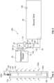
FIG. 1 is a diagram depicting an exemplary particle separation system according to some aspects of the present disclosure; -
FIG. 2 is a top perspective view depicting a separation vessel and a pump system of the particle separation system depicted inFIG. 1 ; -
FIG. 3 is a top perspective view of the separation vessel ofFIG. 2 with a top wall removed and depicting a front and side wall as transparent to depict internal elements of the separation vessel including a weir, a filtration unit including one or more filtration packs, and outlet manifolds in fluid communication with the filtration packs; -
FIG. 4 is a top perspective view of a filtration pack positioned within the separation vessel ofFIGS. 2 and3 for separating fluids and solids; -
FIG. 5 is a cross-sectional view of a single filter element of the filtration pack depicted inFIG. 4 , and depicting a flow of fluid through the filter element; -
FIG. 6 is a diagram depicting various possible sensors and instruments that can be utilized within the separation system ofFIG. 1 ; -
FIG. 7 is a partial, top perspective view of a separation vessel with a top wall removed and depicting a filtration unit including a plurality of filtration packs each including a plurality of filter elements; -
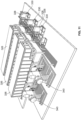
FIG. 8 is a front, top perspective view of a filtration pack ofFIG. 7 ; -
FIG. 9 is a bottom perspective view of a connection between the filter elements of the filtration pack ofFIG. 8 and a manifold; -
FIG. 10 is a bottom perspective view of the filtration pack ofFIG. 8 ; -
FIG. 11 is a top perspective view of an embodiment of a two stage filtration system including any of the methods of particle separation and/or any of the separation vessels disclosed herein; -
FIG. 12 is a diagrammatic view of a portion of the two stage filtration system ofFIG. 11 ; -
FIGS. 13A-13C depict different exemplary configurations for any of the separation vessels disclosed herein; and -
FIGS. 14A-14C depict alternative nesting configurations for filter elements disposed within any filtration pack disclosed herein. - Before any embodiments of the invention are explained in detail, it is to be understood that the invention is not limited in its application to the details of construction and the arrangement of components set forth in the following description or illustrated in the following drawings. The invention is capable of other embodiments and of being practiced or of being carried out in various ways. Also, it is to be understood that the phraseology and terminology used herein is for the purpose of description and should not be regarded as limiting. The use of "including," "comprising," or "having" and variations thereof herein is meant to encompass the items listed thereafter and equivalents thereof as well as additional items. Unless specified or limited otherwise, the terms "mounted," "connected," "supported," and "coupled" and variations thereof are used broadly and encompass both direct and indirect mountings, connections, supports, and couplings. Further, "connected" and "coupled" are not restricted to physical or mechanical connections or couplings.
- The following discussion is presented to enable a person skilled in the art to make and use embodiments of the invention. Various modifications to the illustrated embodiments will be readily apparent to those skilled in the art, and the generic principles herein can be applied to other embodiments and applications without departing from embodiments of the invention. Thus, embodiments of the invention are not intended to be limited to embodiments shown, but are to be accorded the widest scope consistent with the principles and features disclosed herein. The following detailed description is to be read with reference to the figures, in which like elements in different figures have like reference numerals. The figures, which are not necessarily to scale, depict selected embodiments and are not intended to limit the scope of embodiments of the invention. Skilled artisans will recognize the examples provided herein have many useful alternatives and fall within the scope of embodiments of the invention.
- Referring now to
FIG. 1 , an exemplaryparticle separation system 20 is depicted. The particle separation system generally includes a source tank(s) 22 holding pre-separated fluid to be processed by theparticle separation system 20, apump system 24 that is configured to move fluid through theparticle separation system 20, and aseparation vessel 26 for separating solids from fluids. While asource tank 22 is depicted, a pressurized flow (e.g., at a varying flow rate) of pre-separated fluid can be received from some other process or any other suitable source. - Pre-separated fluid is transferred into the source tank(s) 22, for example, by
trucks 28. In the depicted embodiment, thetrucks 28 are filled with pre-separated fluid at a remote location and transported to the location of theparticle separation system 20. The pre-separated fluid can be transferred from thetrucks 28 to the source tank(s) 22 in any suitable manner. In other illustrative embodiments, the pre-separated fluid can be transferred to the source tank(s) 22 is other manners, for example, through a pressurized flow from another location. Alternatively, the pre-separated fluid can be transferred by any suitable vehicle, vessel, or fluid transfer system. Still further, while the fluid in the source tank(s) 22 is referred to herein as being pre-separated fluid, the fluid can be any pre-separated fluid capable of separation into solids and fluids. More particularly, pre-separated fluid refers to any fluid, for example, water, an amine, or any other fluid, that is contaminated by dirt or other debris, hydrocarbons, chemicals, and/or any other contaminants regardless of the form (e.g., solid, liquid, etc.). In some embodiments, the pre-separated fluid is produced water, which is a by-product of hydrocarbon extraction methods and consists of water mixed with oil and particulate of various concentrations. In some embodiments, the pre-separated fluid is waste water, for example, from a refinery, chemical plant, gas plant, or other similar location. In still other embodiments, the pre-separated fluid is industrial waste water, run-off, or construction de-watering. Produced and waste water are both by-products of chemical processes that must be treated before reuse or disposal. - Referring to
FIGS. 1 and2 , the flow of fluid in theparticle separation system 20 is also depicted. Arrow 30 depicts the transfer of pre-separated fluid from, for example, thetrucks 28 to the source tank(s) 22. Pre-separated fluid in the source tank(s) 22 is pumped through a first transfer or inlet line 40 (arrow 42) to thepump system 24 and through a second transfer or outlet line 44 (arrow 46) to theseparation vessel 26. After the pre-separated fluid is filtered in theseparation vessel 26, processed fluid (i.e., pre-separated fluid that has been processed by theseparation vessel 26, for example, water, amine, or any other suitable fluid) is pumped through a third transfer or inlet line 47 (arrow 48) to thepump system 24 and through a fourth transfer or outlet line 50 (arrow 52) back to the source tank(s) 22. While thesource tank 22 for produced and processed fluid is shown as being the same, different tanks or different compartments within the same tank can be utilized. - While a
single source tank 22, asingle pump system 24, and asingle separation vessel 26 are depicted inFIG. 1 , theparticle separation system 20 can include any suitable number ofsource tanks 22,pump systems 24, and/orseparation vessels 26. - The
pump system 24 and theseparation vessel 26 are shown in more detail inFIG. 2 . Thepump system 24 is depicted as having apump outlet 80 in fluid communication with aseparation vessel inlet 82 by way of the second transfer oroutlet line 44 to move pre-separated fluid into theseparation vessel 26. Thepump system 24 includes aninlet pump 84 that pumps pre-separated fluid from the source tank(s) 22, through thesecond transfer line 44 into theseparation vessel 26. The pump system is also depicted as having a plurality ofpump inlets 86 connected to a manifold 88, wherein each of the pump inlets is in fluid communication with a respectiveseparation vessel outlet 90 by way of the third transfer or inlet lines 46. Processed fluid is moved through each of thethird transfer lines 46 into the manifold 88 and through thefourth transfer line 50 to the source tank(s) 22 by anoutlet pump 92. The manifold 88 streamlines each of thethird transfer lines 46 into a single fluid stream to the source tank(s) 22. - The
separation vessel 26 generally includes a top wall or covering 100 (optional), abottom wall 102, and one ormore side walls 104 forming an internal ormain filtration chamber 105 within theseparation vessel 26, as seen inFIGS. 2 and3 . One or more portions of theseparation vessel 26 can be made of fiberglass or another suitable material that can prevent corrosion when pre-separated fluid containing harmful chemicals is processed by theseparation vessel 26. In illustrative embodiments, theseparation vessel 26 is not pressurized (i.e., is at atmospheric pressure). In other illustrative embodiments, theseparation vessel 26 can be pressurized. Theseparation vessel 26 can include aweir 108 spaced from theseparation vessel inlet 82. Theseparation vessel inlet 82 can be positioned adjacent a bottom of theweir 108 such that pre-separated fluid must travel upwardly and over theweir 108. Theweir 108 extends from thebottom wall 102 of theseparation vessel 26 and ends short of afluid height 110 in theseparation vessel 26. Theweir 108 functions to provide "bulk knock out" of very large particles or bulk oil/immiscible liquid content (that will sink to the bottom of theweir 108 and not enter the main filtration chamber 105) and serve as a strong physical barrier to the filtration technology (e.g., filtration unit, filtration pack, filter elements, etc.) in the event a strong pressurized stream enters theseparation vessel 26. In some embodiments, theweir 108 is not utilized. - As seen in
FIGS. 3 and4 , afiltration unit 120 is positioned within theinternal chamber 105 of theseparation vessel 26 after the weir 108 (in a flow path between theseparation vessel inlet 82 and the separation vessel outlet 90). Thefiltration unit 120 is positioned on a suction side of thepump system 24 and can include at least onefiltration pack 122 including a plurality offilter elements 124. Thefiltration pack 122 can include aframe 125 or other structure to which thefilter elements 124 are attached. The frame can include a plurality oftop struts 126, a plurality of bottom struts 128, and a plurality of side struts 130 connecting the pluralities of top and bottom struts 126, 128. Theframe 125 can be constructed of, for example, polyvinyl chloride (PVC), polypropylene, polyethylene, or any other suitable material(s). While aparticular frame 125 is depicted, one skilled in the art would understand that different types of frames could be used to support a plurality offilter elements 124 and allow thefiltration pack 122 to be replaced, as will be discussed in greater detail below. For example, only one of the top struts 126, the bottom struts 128, and the side struts 130 can be utilized, two of the top struts 126, the bottom struts 128, and the side struts 130 can be utilized, or any other configuration can be utilized to hold and position the filtration packs 122. In illustrative embodiments, theframe 125 provides spacing between thefiltration unit 120 and thebottom wall 102 of theseparation vessel 26, which allows for accumulation of solids adjacent thebottom wall 102, as will be discussed in greater detail below. In some embodiments, thefiltration unit 120 and/or the filtration packs 122 are self-supporting in that they can be set within theseparation vessel 26 without being attached to any portion of theseparation vessel 26. - Each
filtration pack 122 can include any suitable number offilter elements 124, for example, between about 10 and about 1000, between about 100 and about 800, between about 200 and about 600, between about 300 and 500, or about 450filter elements 124. In an illustrative embodiments, multiple filtration packs 122 each having 25filter elements 124, can be utilized. In one such embodiment, 18 filtration packs 112 each having 25 filter elements 124 (with a total of 450 filter elements) can be utilized. - While the
filter elements 124 are depicted as being vertical, thefilter elements 124 can optionally be horizontal or one or more filtration packs 122 can include filterelements 124 that are vertical and one or more filtration packs 122 can include filterelements 124 that are horizontal. In illustrative embodiments, each of thefilter elements 124 in thefiltration pack 122 can be parallel to one another. Additionally, while thefilter elements 124 are shown as being nested in a square-shape with parallel rows and columns offilter elements 124, as seen in the top elevational view ofFIG. 14A , thefilter elements 124 can be nested in other configurations. For example, thefilter elements 124 of individual rows can be aligned, but thefilter elements 124 in adjacent rows can be offset, as seen inFIG 14B , thefilter elements 124 can be formed into a hex ring, as seen inFIG. 14C , or thefilter elements 124 can be arranged in any other suitable configuration. Still further, while the filtration packs 122 are shown as being arranged in parallel, the filtration packs 122 can be arranged in series and/or in parallel. - As best seen in
FIG. 5 , eachfilter element 124 can generally includefilter media 140, which can be for example, cylindrical surrounding a centralhollow core 142, a top,open end cap 144 partially enclosing atop end 146 of thefilter media 140, and a bottom,closed end cap 148 enclosing a bottom end 150 of thefilter media 140. A filterelement outlet tube 154 can extend through, for example, the top,open end cap 144 to allow fluid to flow therethrough. Thefilter media 140 can be non-woven and can be made of, for example, glass blown fibers or any other suitable material. In some embodiments, pore size for the media can be between about 1 and about 500 micrometers. The top,open end cap 144 can be made of, for example, polyester or any other suitable material. In addition, the top,open end cap 144 can include a compression fitting for creating a fluid-tight seal with the filterelement outlet tube 154. The bottom,closed end cap 148 can be made of, for example, glass-filled nylon or any other suitable material. - Pre-separated fluid moves from an outside of the
filter media 140, through thefilter media 140, into the centralhollow core 142, and out the filterelement outlet tube 154, as shown byarrows 155a-155c, as seen inFIG. 5 . Each of the filterelement outlet tubes 154 combine into anoutlet manifold 156 for movement out of theseparation vessel 26. Each of the outlet manifolds 156 is in fluid communication with a respectivethird transfer line 47 to transfer fluid through the manifold 88 to the source tank(s) 22. Eachfiltration pack 122 can include any suitable number ofoutlet manifolds 156 in fluid communication with any suitable number offilter elements 124. - In illustrative embodiments, the
filtration unit 120 includes at least two filtration packs 122. In illustrative embodiments, thefiltration unit 120 includes twofiltration packs 122, each including 64filter elements 124, as seen inFIG. 3 . As described above, each of the filtration packs 122 includes aframe 125, whereinadjacent frames 125 can be removably attached to one another. - While the
separation vessel 26 is shown as being generally rectangular in shape, one skilled in the art will understand that theseparation vessel 26 can have any suitable shape, for example, square-shaped, cylindrical, or any other suitable geometric shape. In illustrative embodiments, theseparation vessel 26 can include sloped inner surfaces 157 (FIG. 13A ) to allow solids separated by thefilter elements 124 to collect in acentral collection region 158. In other illustrative embodiments, thebottom wall 102 can be sloped, as seen inFIG. 13B . In still other illustrative embodiments, theseparation vessel 26 can be cylindrical in shape with aninverted cone bottom 159, as seen inFIG. 13C . In illustrative embodiments, theseparation vessel 26 can include one or more drains 161 in thebottom wall 102, adjacent thebottom wall 102, or in any other suitable location to remove collected solids from theseparation vessel 26. - The
filtration unit 120, including the filtration packs 122 and theindividual filter elements 124 of the filtration packs 122, in combination with the rate of flow through theseparation vessel 26 create a low flux through thefiltration unit 120. More particularly, by increasing the number of overall filter elements 124 (e.g., by including a number of filtration packs 122 or asingle filtration pack 122 with multiple filter elements 124), a total square footage of filter media is increased or maximized. In illustrative embodiments, the flux through thefilter elements 124 can be less between about 0.04 liters per minute per square meter and about 2 liters per minute per square meter (about 0.001 gallons per minute per square foot (GPM/ft2) and about 0.05 GPM/ft2). In other illustrative embodiments, the flux through thefilter elements 124 can be less than or equal to about 0.4 liters per minute per square meter (0.01 GPM/ft2). In still other illustrative embodiments, the flux through thefilter elements 124 can be less than or equal to about 0.32 liters per minute per square meter (about 0.008 GPM/ft2). In yet other illustrative embodiments, the flux through thefilter elements 124 can be less than or equal to about 0.2 liters per minute per square meter (about 0.005 GPM/ft2). In some embodiments, the flux through thefilter elements 124 can be between about 0.04 liters per minute per square meter and about 0.4 liters per minute per square meter, or about 0.2 liters per minute per square meter (about 0.001 GPM/ft2 and about 0.01 GPM/ft2, or about 0.005 GPM/ft2). To achieve the desired flux, the flow of pre-separated fluid into theseparation vessel 26 and processed fluid out of theseparation vessel 26 can be the same. In some illustrative embodiments, the flow of pre-separated fluid into theseparation vessel 26 and the flow of processed fluid out of theseparation vessel 26 can be between about 38 liters per minute and about 3800 liters per minute (LPM) (about 10 gallons per minute (GPM) and about 1000 GPM). In other embodiments, both flows can be between about 38 liters per minute and about 2280 liters per minute or between about 190 liters per minute and 1520 (about 10 GPM and about 600 GPM or between about 50 GPM and about 400 GPM). In yet other illustrative embodiments, the flow can be about 1140 or about 1330 liters per minute (LPM) (about 300 or about 350 GPM). The flow rate can vary, so an overall surface area of thefilter elements 124 can be varied to achieve a flux within the ranges desired herein. In some illustrative embodiments, the flow of pre-separated fluid into theseparation vessel 26 and processed fluid out of theseparation vessel 26 can be different. - In some embodiments, the flow rate through the vessel 26 (and thus, through the filtration unit 120) is variable (per the ranges discussed above). In such embodiments, the filter element surface area can be varied in order to achieve the target flux rates discussed above. In this manner, the number of filtration packs 122 and/or the dimensions of the
filter elements 124 within afiltration pack 122 can be varied to achieve the target flux rates for a particular flow rate. In this manner, the filtration packs 122 are modular, as will be discussed in greater detail below, in that each pack can be individually inserted and removed from thevessel 26. - An increased square footage of filter media minimizes the flow rate per media area (or flux). At very low flux rates per unit of media area, the dirt or particle holding capacity of the
filtration unit 120, the filtration packs 122, and theindividual filter elements 124 increases exponentially, which leads to longer operation time before thefiltration unit 120, the filtration pack(s) 122, and/or theindividual filter elements 124 need to be changed due to limited differential pressure. The mechanism of ultra-low flux theory is that particles do not have a large enough face velocity to penetrate or clog pores in thefilter media 140 of thefilter elements 124. More particularly, solid particles hit thefilter media 140 and fall to the bottom of theseparation vessel 26, rather than collecting in thefilter media 140. Conversely, at a higher flux, the particles would have a large enough face velocity to penetrate and clog the pores in thefilter media 140 of thefilter elements 124. The systems described herein capitalize on the ultra-low flux theory by increasing the number offilter elements 124 through which the pre-separated fluid flows, thereby decreasing the flux to a low enough number that filterelement 124 life (and, thus,filtration unit 120 andfiltration pack 122 life) is lengthened from several days to months. This increased life decreases operational expenditures dramatically, as will be discussed in more detail herein. - The
particle separation system 20 can include acontrol system 168 for controlling operation of thesystem 20. In some embodiments, as seen inFIG. 6 , thepump system 24 includes inlet and outlet pumps 170, 172, which can be controlled by variable frequency drives. In some embodiments, thecontrol system 168 can include electronically actuatedball valves second transfer lines separation vessel 26 and through the third andfourth transfer lines separation vessel 26, respectively. In some embodiments, thecontrol system 168 can include one ormore flow meters second transfer lines fourth transfer lines separation vessel 26, respectively. In some embodiments, thecontrol system 168 can include apressure sensor 182 within the first and/orsecond transfer lines separation vessel 26. In some embodiments, the control system can include one ormore level sensors 184 within theseparation vessel 26 for monitoring a level of fluid within theseparation vessel 26. One ormore level sensors 186 can also be included in the source tank(s) 22 for monitoring a level of fluid. Thecontrol system 168 receives feedback from the various sensors within theparticle separation system 20 and changes parameters of the system based on such feedback. The feedback can include, but is not limited to, inlet flow rate, outlet flow rate, sensing of different conditions, alarms, notifications, or any other suitable feedback. - Referring now to
FIG. 7 , a further embodiment of aseparation vessel 226 is depicted. Theseparation vessel 226 can be included in any of the systems disclosed herein, can include any of the features described above with respect toFIGS. 1-6 , and can function in the same manner (i.e., at a high flow rate and/or low flux). Theseparation vessel 226 includes a filtration unit 220 with a plurality of filtration packs 222 including a plurality offilter elements 224. The filtration unit 220 will now be described in detail, it being understood that all other components and features of the separation vessel 226 (and the system in which theseparation 226 vessel is employed) can be as disclosed with respect to thevessel 26 ofFIGS. 1-6 and the system in which thevessel 26 is employed, for example, as seen inFIGS. 14A-14C . - The
separation vessel 226 includes a plurality ofwalls 230 forming theseparation vessel 226 that form an internal or main filtration chamber 232. The filtration packs 222 of the filtration unit 220 occupy at least a portion of the internal chamber 232. Referring toFIG. 8 , eachfiltration pack 222 can generally include a plurality offilter elements 224 arranged in a parallel manner. In some embodiments, thefiltration unit 222 includes 25filter elements 124, for example, in a five by five orientation. In other embodiments, any number of filter elements in any orientation can be utilized. - First ends 234 of the
filter elements 224 can be positioned in aframe 236 and second ends 238 of thefilter elements 224 can be connected to amanifold 240. Theframe 236, which can be made of steel or another suitable material, can include a plurality of slots (not shown) for insertion of a second end 238 of eachfilter element 224 in each of the slots to retain thefilter elements 224 within theframe 236 and in relation to one another. In other embodiments, thefilter elements 224 can be retained within theframe 236 in any suitable manner. The manifold 240, as seen inFIGS. 8 and9 , is a hollow structure with a plurality ofinput ports 242 for connection of anoutlet tube 244 of eachfilter element 224 and anoutlet port 243, as will be discussed in greater detail below. In some embodiments, eachoutlet tube 244 can fit within acorresponding port 242 of the manifold 240 through an interference fit. In such an embodiment, an O-ring 150 can be positioned around theoutlet tube 244 to further the interference fit, create a seal, and prevent leakage between theoutlet tube 244 and theport 242. Theports 242 and theoutlet tubes 244 are positioned and aligned such that each of thefilter elements 224 of thefiltration pack 222 can be connected to the manifold 240 at the same time. In other embodiments, theinput ports 242 and theoutlet tubes 244 can be formed in any suitable manner that would provide for quick and easy attachment of a plurality ofoutlet tubes 244 of a plurality offilter elements 224 to a plurality ofinput ports 242 of asingle manifold 240 at the same time. - As further seen in
FIG. 9 , thefiltration pack 222 can include a number ofarms 260 connecting theframe 236 and the manifold 240 and including looped ends 262 that allow for connection of an apparatus for lifting thefiltration pack 222. In some embodiments, thearms 260 can be in the form of straps or another suitable flexible elements. In other embodiments, the arms are made of a more rigid material. Thearms 260 hold thefilter elements 224, theframe 236, and the manifold 240 together. Further, eachfiltration pack 222 can be lifted by the looped ends 262 of thearms 260 to insert and remove the filtration packs 222 from theseparation vessel 226. In other embodiments, thearms 260 can include any other suitable structure for holding and moving the filtration packs 222. As seen inFIG. 7 , a plurality of filtration packs 222 (that are the same or different) can be inserted into theseparation vessel 226. While the filtration packs 222 are shown as occupying most of theseparation vessel 226, the filtration packs 222 may not occupy the entire separation vessel 226 (i.e., there can be open space within the vessel 226). - As best seen in
FIG. 10 , a bottom perspective view of thefiltration pack 222 is depicted. Eachfiltration pack 222 includes a moldedend cap structure 263 that is separate from or an integral part of theframe 236. Theend cap structure 263 is molded in a square shape and can include a number of alignment structures 264 (e.g., circular slots, apertures, or other aligning structures) for holding ends of each of thefilter elements 224 in position. Thealignment structures 264 can further include connectingstructures 265 that couple thealignment structures 264 to individual square-shapedmembers 266 that together form theend cap structure 263. While one particular member of providing alignment features to ends of thefilter elements 224 is depicted, any other suitable alignment feature can be utilized. Further, the shape of theframe 236 and/or moldedend cap structure 263 can be varied to accommodatefiltration packs 222 of different shapes and/or sizes. - Referring back to
FIG. 7 , theseparation vessel 226 further includes processedfluid conduits 270 on opposing sides of theseparation vessel 226. Theconduits 270 can be attached to an inner surface of awall 230 of theseparation vessel 226 by brackets or any other suitable manner. Theconduits 270 are configured to transport clean fluid (i.e., by pulling the fluid through thevessel 226 utilizing a downstream pump) from the filtration packs 222 out of theseparation vessel 226. More particularly,pack conduits 272 are connected between each ofoutlet portion 243 and a respective processedfluid conduit 270. - When the filtration packs 222 are first inserted into the
separation vessel 226, thefilter elements 224 are clean and dry and, thus, create an upward buoyant force. In order to retain the filtration packs 222 in place within the separation vessel 226 (in a vertical direction), retention straps 280 can be attached, for example by brackets or any other suitable mechanism, to opposingwalls 230 of theseparation vessel 226. In some embodiments, the retention straps 280 are positioned immediately above themanifolds 240 when theframe 236 is positioned on a bottom wall of theseparation vessel 26. In other embodiments, the retention straps 280 can be located at any suitable position. While the retention straps 280 are shown as being made of a flexible material, thestraps 280 may alternatively be made of a rigid material or a combination of flexible and rigid materials. - Still referring to
FIG. 7 , themanifold 240 of each of the filtration packs 222 is coupled to theconduits 270 by thepack conduits 272. As described in detail above, the contaminated is pulled through theseparation vessel 226 by a pump downstream of theseparation vessel 226. In this manner, the systems disclosed herein are non-pressurized or lack a pressurized vessel (i.e., the system is at atmospheric pressure). Instead, the systems disclosed herein utilize a suction-side pump that draws fluid through the system. One advantage of a non-pressurized system is cost. Pressurized systems require specific vessels that cost significantly more for the same amount of filtration. Utilizing a non-pressurized system eliminates the need for such expensive vessels. - In some embodiments, as seen in
FIGS. 11 and12 , any of the separation vessels herein can be included as part of a two (or more) stage filtration system 300. For example, the separation vessels discussed herein are utilized to separate particles from a pre-separated fluid and/or to skim oil from an oil/water emulsion. It may also be desirous to provide a coalescing stage to remove oil and/or to provide other filtration steps. Some systems 300 can include any number of separation vessels 326 (which can be any of the separation vessels disclosed herein). Pre-separated fluid is provided from a tank or other site (seeFIG. 12 ) through a distribution manifold to a number ofdifferent separation vessels 326. The pre-separated fluid is pulled through each of theseparation vessels 326 by arespective pump 328 positioned, for example, on apump skid 330. Thepumps 328 can then pump processed or treated fluid from theseparation vessels 326 to additional treatment stages, for example,coalescers 340, which remove oil from the treated fluid. A collection manifold 342 can be positioned between thepumps 328 and theadditional filtration stages 340 to control the flow therebetween and to monitor the fluid (e.g., the quality, pressure, etc.) flowing therebetween. While coalescers are discussed, any additional filtration treatment process(es) can be utilized in combination with theseparation vessels 326 and/or numerous additional filtration treatment processes can be utilized. In some embodiments, absorption beds can be utilized. In other embodiments, the other filtration or treatment processes can be pre-treatment processes in that they can be positioned upstream (i.e., before) theseparation vessels 326. - In any of the embodiments discloses herein, one or more aerators or bubblers can be disposed, for example, on the
bottom wall 102, one ormore side walls 104, or at any other suitable location within theseparation vessel 26. The aerator or bubbler would act to inject air (or possibly a fluid, such as water) into theseparation vessel 26 to create a disturbance, which may assist in moving fluid through theseparation vessel 26 and/or in the filtration process. - In any of the embodiments discloses herein, a back-pulsing operation may be implemented within any of the systems. More particularly, the flow through the separation vessel may be reversed to remove solids from the filter elements of one or more filtration packs, and then may be returned to the original flow direction. The back-pulsing operation may improve the life of the individual filter elements.
- As can be seen from the foregoing figures, the
separation vessels separation vessel separation vessel separation vessel pump system 24 and can be removed from theparticle separation system 20 and anew separation vessel original separation vessel separation vessel filter elements separation vessel particle separation system 20, theseparation vessel pump system new separation vessel old separation vessel filter elements separation vessel separation vessel separation vessel - In some embodiments, the
separation vessel separation vessel outlet manifolds separation vessel separation vessel separation vessel filtration packs - In some embodiments, the systems disclosed herein can be offered as a rental model. In this manner, site personnel do not need to remove and replace hundreds of filter elements at once. Rather, the entire separation vessel may be removed from a particular site and replace with a new separation vessel. This model also greatly reduces downtime, as it takes significant time to remove and replace hundreds of filtration elements.
- While the various embodiments of the
particle separation system 20 described herein have been described as a standalone system, theparticle separation system 20 may optionally be used in combination with any other filtration, separation, or any other suitable systems. In illustrative embodiments, one or moreparticle separation systems 20 may be utilized in combination with one or more of hydrocarbon recovery technology, liquid-liquid separation technology, solids removal technology, or any other technologies for processing, filtering, and/or cleaning fluids.
Claims (7)
- A particle separation system (20), comprising:a vessel (26) having at least one side wall (104) and a bottom wall (102) forming an internal chamber (105) within the vessel (26);a filtration unit (220) positioned within the vessel (26) and comprising:a first filtration pack (222) comprising a first plurality of filter elements (224) having a first plurality of outlets (244);a first hollow manifold (240) having a first plurality of inlets (242), a number of the first plurality of inlets (242) being equal to a number of the first plurality of outlets (244), the first plurality of outlets (244) and the first plurality of inlets (242) being capable of coupling such that a flow through each of the first plurality of filter elements (224) enters the first manifold (240);the first hollow manifold (240) including a first outlet channel (243) for flow from the first manifold (240) to a processed fluid conduit (270);a second filtration pack (222) comprising a second plurality of filter elements (224) having a second plurality of outlets (244);a second hollow manifold (240) having a second plurality of inlets (242), a number of the second plurality of inlets (242) being equal to a number of the second plurality of outlets (244), the second plurality of outlets (244) and the second plurality of inlets (242) being capable of coupling such that a flow through each of the second plurality of filter elements (224) enters the second manifold (240);the second hollow manifold (240) including a second outlet channel (243) for flow from the second manifold (240) to the processed fluid conduit (270);wherein each of the first and second filtration packs (222) is modular in that each of the first and second filtration packs (222) can be individually inserted and removed from the vessel (26) such that each of the first plurality of filter elements (224) are insertable and/or removable together and each of the second plurality of filter elements (224) are insertable and/or removable together.
- The particle separation system (20) of Claim 1, wherein the first plurality of outlets (244) of the first filtration pack (222) are positioned and aligned such that attachment of the first plurality of outlets (244) of the first plurality of filter elements (224) to the first plurality of inlets (242) of the first single manifold (240) occurs at the same time and wherein the second plurality of outlets (244) of the second filtration pack (222) are positioned and aligned such that attachment of the second plurality of outlets (244) of the second plurality of filter elements (224) to the second plurality of inlets (242) of the second single manifold (240) occurs at the same time.
- The particle separation system (20) of Claim 2, wherein pre-separated fluid flows into the vessel (26) at a rate of between about 38 liters per minute and about 3800 liters per minute (LPM) (about 10 and about 1000 gallons per minute (GPM)) and the filtration unit (220) is configured to provide a flux within the filtration unit less than or equal to about 2 liters per minute per square meter (LPM/m2) (about 0.05 gallons per minute per square foot (GPM/ft2)).
- The particle separation system (20) of Claim 1 or Claim 2 or Claim 3, further including:a first frame (236) for holding the first filtration pack (222), the first frame (236) including a first end cap structure (263) for holding ends of each of the first plurality of filter elements (224); anda second frame (236) for holding the second filtration pack (222), the second frame (236) including a second end cap structure (263) for holding ends of each of the second plurality of filter elements (224); and, optionally or preferably, further including:a first set of arms (260) extending between the first frame (236) and the first manifold (240), the first set of arms (260) connecting the first frame (236) and the first manifold (240) and retaining the first plurality of filter elements (224) in position; anda second set of arms (260) extending between the second frame (236) and the second manifold (240), the second set of arms (260) connecting the second frame (236) and the second manifold (240) and retaining the second plurality of the filter elements (224) in position.
- The particle separation system (20) of Claim 1 or of any of claims 2 to 4, wherein pre-separated fluid is moved through the vessel (26) using a pump (24) positioned downstream of the vessel (26); and/or further including a plurality of vessels (26) and a plurality of pumps (24) for moving pre-separated fluid through the plurality of vessels (26).
- The particle separation system (20) of Claim 1, wherein the vessel (26) includes the bottom wall (102) having at least one surface (157) that is sloped inwardly toward a central collection region (158); and, optionally or preferably, further including a drain (161) for removing debris that has settled at a central collection region (158) of the vessel (26).
- The particle separation system (20) of any of claims 1 to 6, further including at least one of: an aerator disposed within the vessel (26), a back-pulsing operation, and oil skimming; and/or wherein the rate of pre-separated fluid flow into the vessel (26) and the rate of processed fluid flow out of the vessel (26) are not the same.
Applications Claiming Priority (2)
| Application Number | Priority Date | Filing Date | Title |
|---|---|---|---|
| US201662419296P | 2016-11-08 | 2016-11-08 | |
| PCT/US2017/060457 WO2018089381A1 (en) | 2016-11-08 | 2017-11-07 | Particle separation system and method |
Publications (3)
| Publication Number | Publication Date |
|---|---|
| EP3538242A1 EP3538242A1 (en) | 2019-09-18 |
| EP3538242A4 EP3538242A4 (en) | 2020-06-17 |
| EP3538242B1 true EP3538242B1 (en) | 2024-10-30 |
Family
ID=62065906
Family Applications (1)
| Application Number | Title | Priority Date | Filing Date |
|---|---|---|---|
| EP17868893.3A Active EP3538242B1 (en) | 2016-11-08 | 2017-11-07 | Particle separation system |
Country Status (4)
| Country | Link |
|---|---|
| US (3) | US10960328B2 (en) |
| EP (1) | EP3538242B1 (en) |
| CN (1) | CN110430929B (en) |
| WO (1) | WO2018089381A1 (en) |
Families Citing this family (3)
| Publication number | Priority date | Publication date | Assignee | Title |
|---|---|---|---|---|
| US10967300B2 (en) * | 2017-08-29 | 2021-04-06 | Green Flow Industries, LLC | Transportable separation and monitoring apparatus with auger |
| CA3138508C (en) * | 2019-05-03 | 2023-08-22 | Gen-Probe Incorporated | System and method for managing liquid waste |
| KR20210132921A (en) * | 2020-04-28 | 2021-11-05 | 주식회사 아모그린텍 | filter module for water-purifying device using gravity and water-purifying device including the same |
Family Cites Families (34)
| Publication number | Priority date | Publication date | Assignee | Title |
|---|---|---|---|---|
| US3744633A (en) | 1971-01-18 | 1973-07-10 | Industrial Filter Pump Mfg Co | Filter apparatus and method of filtration |
| US4349434A (en) * | 1980-01-07 | 1982-09-14 | Jaworski William R | Filtration system for spas, hot tubs, swimming pools and the like |
| US4552669A (en) * | 1983-04-18 | 1985-11-12 | Mott Metallurgical Corporation | Pneumatic hydro-pulse filter system and method of operation |
| IE903487A1 (en) * | 1989-09-29 | 1991-04-10 | Memtec Ltd | Filter cartridge manifold |
| US5330638A (en) | 1990-05-22 | 1994-07-19 | Filtercorp Partners L.P. | Commercial filtering system |
| US5133871A (en) | 1990-06-12 | 1992-07-28 | Ehud Levy | Water filter |
| US5427679A (en) * | 1990-10-23 | 1995-06-27 | Daniels; Byron C. | Septic system filter assembly, filter arrangement |
| US5183572A (en) * | 1991-08-23 | 1993-02-02 | Curtis Manufacturing Company, Inc. | Cross-flow filtration system and method for filtering a solvent-particulate waste stream |
| DE4322894A1 (en) | 1993-07-09 | 1995-01-12 | Mann & Hummel Filter | Liquid filter |
| US5411665A (en) * | 1993-07-20 | 1995-05-02 | Scraggs; Charles R. | Methods for reducing and separating emulsions and homogeneous components from contaminated water |
| US6488842B2 (en) * | 1999-02-26 | 2002-12-03 | Tadayoshi Nagaoka | Filtering device |
| AUPP985099A0 (en) * | 1999-04-20 | 1999-05-13 | Usf Filtration And Separations Group Inc. | Membrane filtration manifold system |
| US6773612B2 (en) * | 2001-03-30 | 2004-08-10 | Richard A. Dias | Sloped screen separator that removes solids from a manure slurry |
| BRPI0413926A (en) | 2003-08-27 | 2006-10-24 | 3M Innovative Properties Co | water filtration system, water collector, method of installing a water filtration system and pipe connector |
| WO2005070524A1 (en) * | 2004-01-09 | 2005-08-04 | Trisep Corporation | Filtration with low-fouling, high-flow, low-energy spiral wound membrane cartridges |
| US7481919B1 (en) * | 2004-03-26 | 2009-01-27 | Keenan Andrew D | Multiple filter controller |
| WO2005118115A1 (en) * | 2004-05-26 | 2005-12-15 | Trisep Corporation | Network for supporting spiral wound membrane cartridges for submerged operation |
| CA2784249C (en) * | 2006-02-09 | 2015-08-11 | Alcoa Inc. | Methods, apparatus and systems for polishing wastewater utilizing, natural media filtration |
| US8123935B2 (en) * | 2007-08-15 | 2012-02-28 | Monteco Ltd. | Filter for removing sediment from water |
| EP2550081A4 (en) * | 2010-03-25 | 2013-08-14 | Mpc Inc | Filter assembly |
| US20130221546A1 (en) * | 2012-02-29 | 2013-08-29 | Veolia Water Solutions & Technologies Support | Flat Sheet Membrane Module |
| US20130319925A1 (en) * | 2012-06-01 | 2013-12-05 | Eaton Corporation | Fluid filtration system |
| US8734555B2 (en) * | 2012-06-12 | 2014-05-27 | Bha Altair, Llc | Device for filtering fluid in a power generating system |
| EP2903727A2 (en) * | 2012-10-01 | 2015-08-12 | Entegris, Inc. | Purification system |
| US9440170B2 (en) * | 2012-12-13 | 2016-09-13 | Eaton Corporation | Liquid filter apparatus |
| US9744485B2 (en) * | 2013-08-16 | 2017-08-29 | Pecofacet (Us), Inc. | Fluid treatment system |
| US9447911B2 (en) * | 2014-03-07 | 2016-09-20 | Pall Corporation | Adjustable frame assemblies, methods for assembling a filter apparatus, and filter apparatuses |
| CN103922527B (en) * | 2014-03-25 | 2015-11-25 | 河海大学 | Integrated sewage water advanced treatment apparatus and technique thereof |
| US20150299583A1 (en) * | 2014-04-21 | 2015-10-22 | Pentair Filtration Solutions, Llc | Separation system and method |
| WO2015164528A1 (en) | 2014-04-23 | 2015-10-29 | Baird Michael T | Water filter cartridge and manifold head seal |
| CN203938563U (en) * | 2014-05-29 | 2014-11-12 | 凯天环保科技股份有限公司 | A kind of microkinetic integrated sewage treating apparatus |
| CN204778900U (en) * | 2015-07-13 | 2015-11-18 | 沛毅工业股份有限公司 | Multicore filter with takeover of catchmenting |
| CN105169786B (en) * | 2015-09-10 | 2017-08-29 | 中广核研究院有限公司 | Nuclear island safety shell recirculating filter |
| US10167219B2 (en) * | 2016-09-21 | 2019-01-01 | Thomas Wang | Ecological biowater purification system |
-
2017
- 2017-11-07 CN CN201780082073.1A patent/CN110430929B/en active Active
- 2017-11-07 WO PCT/US2017/060457 patent/WO2018089381A1/en not_active Ceased
- 2017-11-07 US US15/806,245 patent/US10960328B2/en active Active
- 2017-11-07 EP EP17868893.3A patent/EP3538242B1/en active Active
-
2021
- 2021-03-30 US US17/301,270 patent/US11638890B2/en active Active
-
2023
- 2023-05-02 US US18/311,185 patent/US12070704B2/en active Active
Also Published As
| Publication number | Publication date |
|---|---|
| US10960328B2 (en) | 2021-03-30 |
| CN110430929B (en) | 2022-12-27 |
| CN110430929A (en) | 2019-11-08 |
| US20230264124A1 (en) | 2023-08-24 |
| US11638890B2 (en) | 2023-05-02 |
| US12070704B2 (en) | 2024-08-27 |
| WO2018089381A1 (en) | 2018-05-17 |
| US20180126306A1 (en) | 2018-05-10 |
| EP3538242A4 (en) | 2020-06-17 |
| EP3538242A1 (en) | 2019-09-18 |
| US20210213377A1 (en) | 2021-07-15 |
Similar Documents
| Publication | Publication Date | Title |
|---|---|---|
| US12070704B2 (en) | Particle separation system and method | |
| US7241382B2 (en) | Method and system for filtering sediment-bearing fluids | |
| US5035799A (en) | Filter assembly | |
| US20070144969A1 (en) | Method and system for filtering sediment-bearing fluids | |
| CA2921868C (en) | Method and apparatus for purifying contaminated liquids such as sour water | |
| CN1964770A (en) | Self cleaning gas filtering system and method | |
| CA2885789C (en) | Mobile fluid treatment system and associated apparatus | |
| WO2003075646A1 (en) | Waste extraction system | |
| US20070187328A1 (en) | Method and system for filtering sediment-bearing fluids | |
| CN105813720B (en) | Immersion filter | |
| US4964987A (en) | Cross flow filter apparatus | |
| US10960405B2 (en) | Magnetic filter | |
| US20130134087A1 (en) | Separating apparatus and method | |
| CN204672002U (en) | A kind of vortex gravity centrifugal pipeline dirt separator | |
| CN217887072U (en) | Secondary separation device for waste water | |
| KR101269582B1 (en) | Sand filter and fitration method using the liquefaction | |
| SU1407517A1 (en) | Filter | |
| CN118110492A (en) | Separator integrated device with three-phase separation function | |
| KR101960775B1 (en) | Submerged-Type Filtration Apparatus | |
| WO2021225476A1 (en) | Sand separation device | |
| JPH1157422A (en) | Septic tank | |
| WO2007007931A1 (en) | Apparatus and system for filtering water for purification |
Legal Events
| Date | Code | Title | Description |
|---|---|---|---|
| STAA | Information on the status of an ep patent application or granted ep patent |
Free format text: STATUS: THE INTERNATIONAL PUBLICATION HAS BEEN MADE |
|
| PUAI | Public reference made under article 153(3) epc to a published international application that has entered the european phase |
Free format text: ORIGINAL CODE: 0009012 |
|
| STAA | Information on the status of an ep patent application or granted ep patent |
Free format text: STATUS: REQUEST FOR EXAMINATION WAS MADE |
|
| 17P | Request for examination filed |
Effective date: 20190531 |
|
| AK | Designated contracting states |
Kind code of ref document: A1 Designated state(s): AL AT BE BG CH CY CZ DE DK EE ES FI FR GB GR HR HU IE IS IT LI LT LU LV MC MK MT NL NO PL PT RO RS SE SI SK SM TR |
|
| AX | Request for extension of the european patent |
Extension state: BA ME |
|
| DAV | Request for validation of the european patent (deleted) | ||
| DAX | Request for extension of the european patent (deleted) | ||
| A4 | Supplementary search report drawn up and despatched |
Effective date: 20200518 |
|
| RIC1 | Information provided on ipc code assigned before grant |
Ipc: B01D 35/027 20060101ALI20200512BHEP Ipc: C10L 1/00 20060101ALI20200512BHEP Ipc: B01D 21/02 20060101ALI20200512BHEP Ipc: B01D 29/11 20060101ALI20200512BHEP Ipc: B01D 35/30 20060101ALI20200512BHEP Ipc: B01D 29/60 20060101ALI20200512BHEP Ipc: B01D 25/02 20060101AFI20200512BHEP Ipc: B01D 29/05 20060101ALI20200512BHEP Ipc: B01D 29/52 20060101ALI20200512BHEP Ipc: B01D 29/66 20060101ALI20200512BHEP Ipc: C10G 31/09 20060101ALI20200512BHEP |
|
| STAA | Information on the status of an ep patent application or granted ep patent |
Free format text: STATUS: EXAMINATION IS IN PROGRESS |
|
| 17Q | First examination report despatched |
Effective date: 20210924 |
|
| GRAP | Despatch of communication of intention to grant a patent |
Free format text: ORIGINAL CODE: EPIDOSNIGR1 |
|
| STAA | Information on the status of an ep patent application or granted ep patent |
Free format text: STATUS: GRANT OF PATENT IS INTENDED |
|
| INTG | Intention to grant announced |
Effective date: 20240123 |
|
| GRAJ | Information related to disapproval of communication of intention to grant by the applicant or resumption of examination proceedings by the epo deleted |
Free format text: ORIGINAL CODE: EPIDOSDIGR1 |
|
| STAA | Information on the status of an ep patent application or granted ep patent |
Free format text: STATUS: EXAMINATION IS IN PROGRESS |
|
| GRAP | Despatch of communication of intention to grant a patent |
Free format text: ORIGINAL CODE: EPIDOSNIGR1 |
|
| STAA | Information on the status of an ep patent application or granted ep patent |
Free format text: STATUS: GRANT OF PATENT IS INTENDED |
|
| INTG | Intention to grant announced |
Effective date: 20240607 |
|
| GRAS | Grant fee paid |
Free format text: ORIGINAL CODE: EPIDOSNIGR3 |
|
| GRAA | (expected) grant |
Free format text: ORIGINAL CODE: 0009210 |
|
| STAA | Information on the status of an ep patent application or granted ep patent |
Free format text: STATUS: THE PATENT HAS BEEN GRANTED |
|
| AK | Designated contracting states |
Kind code of ref document: B1 Designated state(s): AL AT BE BG CH CY CZ DE DK EE ES FI FR GB GR HR HU IE IS IT LI LT LU LV MC MK MT NL NO PL PT RO RS SE SI SK SM TR |
|
| REG | Reference to a national code |
Ref country code: GB Ref legal event code: FG4D |
|
| REG | Reference to a national code |
Ref country code: CH Ref legal event code: EP |
|
| REG | Reference to a national code |
Ref country code: IE Ref legal event code: FG4D |
|
| REG | Reference to a national code |
Ref country code: DE Ref legal event code: R096 Ref document number: 602017085835 Country of ref document: DE |
|
| P01 | Opt-out of the competence of the unified patent court (upc) registered |
Free format text: CASE NUMBER: APP_494/2025 Effective date: 20250107 |
|
| REG | Reference to a national code |
Ref country code: LT Ref legal event code: MG9D |
|
| REG | Reference to a national code |
Ref country code: NL Ref legal event code: MP Effective date: 20241030 |
|
| RAP4 | Party data changed (patent owner data changed or rights of a patent transferred) |
Owner name: PENTAIR FILTRATION SOLUTIONS, LLC |
|
| PG25 | Lapsed in a contracting state [announced via postgrant information from national office to epo] |
Ref country code: IS Free format text: LAPSE BECAUSE OF FAILURE TO SUBMIT A TRANSLATION OF THE DESCRIPTION OR TO PAY THE FEE WITHIN THE PRESCRIBED TIME-LIMIT Effective date: 20250228 Ref country code: PT Free format text: LAPSE BECAUSE OF FAILURE TO SUBMIT A TRANSLATION OF THE DESCRIPTION OR TO PAY THE FEE WITHIN THE PRESCRIBED TIME-LIMIT Effective date: 20250228 Ref country code: HR Free format text: LAPSE BECAUSE OF FAILURE TO SUBMIT A TRANSLATION OF THE DESCRIPTION OR TO PAY THE FEE WITHIN THE PRESCRIBED TIME-LIMIT Effective date: 20241030 |
|
| PG25 | Lapsed in a contracting state [announced via postgrant information from national office to epo] |
Ref country code: FI Free format text: LAPSE BECAUSE OF FAILURE TO SUBMIT A TRANSLATION OF THE DESCRIPTION OR TO PAY THE FEE WITHIN THE PRESCRIBED TIME-LIMIT Effective date: 20241030 Ref country code: NL Free format text: LAPSE BECAUSE OF FAILURE TO SUBMIT A TRANSLATION OF THE DESCRIPTION OR TO PAY THE FEE WITHIN THE PRESCRIBED TIME-LIMIT Effective date: 20241030 |
|
| REG | Reference to a national code |
Ref country code: AT Ref legal event code: MK05 Ref document number: 1736368 Country of ref document: AT Kind code of ref document: T Effective date: 20241030 |
|
| PG25 | Lapsed in a contracting state [announced via postgrant information from national office to epo] |
Ref country code: BG Free format text: LAPSE BECAUSE OF FAILURE TO SUBMIT A TRANSLATION OF THE DESCRIPTION OR TO PAY THE FEE WITHIN THE PRESCRIBED TIME-LIMIT Effective date: 20241030 |
|
| PG25 | Lapsed in a contracting state [announced via postgrant information from national office to epo] |
Ref country code: ES Free format text: LAPSE BECAUSE OF FAILURE TO SUBMIT A TRANSLATION OF THE DESCRIPTION OR TO PAY THE FEE WITHIN THE PRESCRIBED TIME-LIMIT Effective date: 20241030 |
|
| PG25 | Lapsed in a contracting state [announced via postgrant information from national office to epo] |
Ref country code: NO Free format text: LAPSE BECAUSE OF FAILURE TO SUBMIT A TRANSLATION OF THE DESCRIPTION OR TO PAY THE FEE WITHIN THE PRESCRIBED TIME-LIMIT Effective date: 20250130 |
|
| PG25 | Lapsed in a contracting state [announced via postgrant information from national office to epo] |
Ref country code: LV Free format text: LAPSE BECAUSE OF FAILURE TO SUBMIT A TRANSLATION OF THE DESCRIPTION OR TO PAY THE FEE WITHIN THE PRESCRIBED TIME-LIMIT Effective date: 20241030 Ref country code: GR Free format text: LAPSE BECAUSE OF FAILURE TO SUBMIT A TRANSLATION OF THE DESCRIPTION OR TO PAY THE FEE WITHIN THE PRESCRIBED TIME-LIMIT Effective date: 20250131 Ref country code: AT Free format text: LAPSE BECAUSE OF FAILURE TO SUBMIT A TRANSLATION OF THE DESCRIPTION OR TO PAY THE FEE WITHIN THE PRESCRIBED TIME-LIMIT Effective date: 20241030 |
|
| PG25 | Lapsed in a contracting state [announced via postgrant information from national office to epo] |
Ref country code: PL Free format text: LAPSE BECAUSE OF FAILURE TO SUBMIT A TRANSLATION OF THE DESCRIPTION OR TO PAY THE FEE WITHIN THE PRESCRIBED TIME-LIMIT Effective date: 20241030 |
|
| PG25 | Lapsed in a contracting state [announced via postgrant information from national office to epo] |
Ref country code: RS Free format text: LAPSE BECAUSE OF FAILURE TO SUBMIT A TRANSLATION OF THE DESCRIPTION OR TO PAY THE FEE WITHIN THE PRESCRIBED TIME-LIMIT Effective date: 20250130 |
|
| REG | Reference to a national code |
Ref country code: DE Ref legal event code: R081 Ref document number: 602017085835 Country of ref document: DE Owner name: PENTAIR FILTRATION SOLUTIONS, LLC, HANOVER PAR, US Free format text: FORMER OWNER: PENTAIR FILTRATION SOLUTIONS, LLC, ST. PAUL, MN, US |
|
| REG | Reference to a national code |
Ref country code: CH Ref legal event code: PL |
|
| PG25 | Lapsed in a contracting state [announced via postgrant information from national office to epo] |
Ref country code: SM Free format text: LAPSE BECAUSE OF FAILURE TO SUBMIT A TRANSLATION OF THE DESCRIPTION OR TO PAY THE FEE WITHIN THE PRESCRIBED TIME-LIMIT Effective date: 20241030 |
|
| PG25 | Lapsed in a contracting state [announced via postgrant information from national office to epo] |
Ref country code: MC Free format text: LAPSE BECAUSE OF FAILURE TO SUBMIT A TRANSLATION OF THE DESCRIPTION OR TO PAY THE FEE WITHIN THE PRESCRIBED TIME-LIMIT Effective date: 20241030 |
|
| PG25 | Lapsed in a contracting state [announced via postgrant information from national office to epo] |
Ref country code: DK Free format text: LAPSE BECAUSE OF FAILURE TO SUBMIT A TRANSLATION OF THE DESCRIPTION OR TO PAY THE FEE WITHIN THE PRESCRIBED TIME-LIMIT Effective date: 20241030 |
|
| PG25 | Lapsed in a contracting state [announced via postgrant information from national office to epo] |
Ref country code: LU Free format text: LAPSE BECAUSE OF NON-PAYMENT OF DUE FEES Effective date: 20241107 |
|
| REG | Reference to a national code |
Ref country code: CH Ref legal event code: PL |
|
| PG25 | Lapsed in a contracting state [announced via postgrant information from national office to epo] |
Ref country code: EE Free format text: LAPSE BECAUSE OF FAILURE TO SUBMIT A TRANSLATION OF THE DESCRIPTION OR TO PAY THE FEE WITHIN THE PRESCRIBED TIME-LIMIT Effective date: 20241030 |
|
| PG25 | Lapsed in a contracting state [announced via postgrant information from national office to epo] |
Ref country code: CH Free format text: LAPSE BECAUSE OF NON-PAYMENT OF DUE FEES Effective date: 20241130 |
|
| PG25 | Lapsed in a contracting state [announced via postgrant information from national office to epo] |
Ref country code: RO Free format text: LAPSE BECAUSE OF FAILURE TO SUBMIT A TRANSLATION OF THE DESCRIPTION OR TO PAY THE FEE WITHIN THE PRESCRIBED TIME-LIMIT Effective date: 20241030 |
|
| PG25 | Lapsed in a contracting state [announced via postgrant information from national office to epo] |
Ref country code: SK Free format text: LAPSE BECAUSE OF FAILURE TO SUBMIT A TRANSLATION OF THE DESCRIPTION OR TO PAY THE FEE WITHIN THE PRESCRIBED TIME-LIMIT Effective date: 20241030 |
|
| PG25 | Lapsed in a contracting state [announced via postgrant information from national office to epo] |
Ref country code: CZ Free format text: LAPSE BECAUSE OF FAILURE TO SUBMIT A TRANSLATION OF THE DESCRIPTION OR TO PAY THE FEE WITHIN THE PRESCRIBED TIME-LIMIT Effective date: 20241030 |
|
| REG | Reference to a national code |
Ref country code: DE Ref legal event code: R097 Ref document number: 602017085835 Country of ref document: DE |
|
| REG | Reference to a national code |
Ref country code: BE Ref legal event code: MM Effective date: 20241130 |
|
| PLBE | No opposition filed within time limit |
Free format text: ORIGINAL CODE: 0009261 |
|
| STAA | Information on the status of an ep patent application or granted ep patent |
Free format text: STATUS: NO OPPOSITION FILED WITHIN TIME LIMIT |
|
| PG25 | Lapsed in a contracting state [announced via postgrant information from national office to epo] |
Ref country code: SE Free format text: LAPSE BECAUSE OF FAILURE TO SUBMIT A TRANSLATION OF THE DESCRIPTION OR TO PAY THE FEE WITHIN THE PRESCRIBED TIME-LIMIT Effective date: 20241030 |
|
| 26N | No opposition filed |
Effective date: 20250731 |
|
| PG25 | Lapsed in a contracting state [announced via postgrant information from national office to epo] |
Ref country code: BE Free format text: LAPSE BECAUSE OF NON-PAYMENT OF DUE FEES Effective date: 20241130 |
|
| PG25 | Lapsed in a contracting state [announced via postgrant information from national office to epo] |
Ref country code: FR Free format text: LAPSE BECAUSE OF NON-PAYMENT OF DUE FEES Effective date: 20241230 |
|
| PG25 | Lapsed in a contracting state [announced via postgrant information from national office to epo] |
Ref country code: IE Free format text: LAPSE BECAUSE OF NON-PAYMENT OF DUE FEES Effective date: 20241107 |
|
| PGFP | Annual fee paid to national office [announced via postgrant information from national office to epo] |
Ref country code: DE Payment date: 20251118 Year of fee payment: 9 |
|
| PGFP | Annual fee paid to national office [announced via postgrant information from national office to epo] |
Ref country code: GB Payment date: 20251120 Year of fee payment: 9 |
|
| PGFP | Annual fee paid to national office [announced via postgrant information from national office to epo] |
Ref country code: IT Payment date: 20251128 Year of fee payment: 9 |