EP3538009B1 - Guidance systems - Google Patents
Guidance systems Download PDFInfo
- Publication number
- EP3538009B1 EP3538009B1 EP17817322.5A EP17817322A EP3538009B1 EP 3538009 B1 EP3538009 B1 EP 3538009B1 EP 17817322 A EP17817322 A EP 17817322A EP 3538009 B1 EP3538009 B1 EP 3538009B1
- Authority
- EP
- European Patent Office
- Prior art keywords
- data
- images
- location
- guidance system
- image
- Prior art date
- Legal status (The legal status is an assumption and is not a legal conclusion. Google has not performed a legal analysis and makes no representation as to the accuracy of the status listed.)
- Active
Links
Images




Classifications
-
- A—HUMAN NECESSITIES
- A61—MEDICAL OR VETERINARY SCIENCE; HYGIENE
- A61B—DIAGNOSIS; SURGERY; IDENTIFICATION
- A61B1/00—Instruments for performing medical examinations of the interior of cavities or tubes of the body by visual or photographical inspection, e.g. endoscopes; Illuminating arrangements therefor
- A61B1/00002—Operational features of endoscopes
- A61B1/00004—Operational features of endoscopes characterised by electronic signal processing
- A61B1/00009—Operational features of endoscopes characterised by electronic signal processing of image signals during a use of endoscope
-
- A—HUMAN NECESSITIES
- A61—MEDICAL OR VETERINARY SCIENCE; HYGIENE
- A61B—DIAGNOSIS; SURGERY; IDENTIFICATION
- A61B1/00—Instruments for performing medical examinations of the interior of cavities or tubes of the body by visual or photographical inspection, e.g. endoscopes; Illuminating arrangements therefor
- A61B1/00163—Optical arrangements
- A61B1/00172—Optical arrangements with means for scanning
-
- A—HUMAN NECESSITIES
- A61—MEDICAL OR VETERINARY SCIENCE; HYGIENE
- A61B—DIAGNOSIS; SURGERY; IDENTIFICATION
- A61B1/00—Instruments for performing medical examinations of the interior of cavities or tubes of the body by visual or photographical inspection, e.g. endoscopes; Illuminating arrangements therefor
- A61B1/04—Instruments for performing medical examinations of the interior of cavities or tubes of the body by visual or photographical inspection, e.g. endoscopes; Illuminating arrangements therefor combined with photographic or television appliances
-
- A—HUMAN NECESSITIES
- A61—MEDICAL OR VETERINARY SCIENCE; HYGIENE
- A61B—DIAGNOSIS; SURGERY; IDENTIFICATION
- A61B1/00—Instruments for performing medical examinations of the interior of cavities or tubes of the body by visual or photographical inspection, e.g. endoscopes; Illuminating arrangements therefor
- A61B1/06—Instruments for performing medical examinations of the interior of cavities or tubes of the body by visual or photographical inspection, e.g. endoscopes; Illuminating arrangements therefor with illuminating arrangements
- A61B1/063—Instruments for performing medical examinations of the interior of cavities or tubes of the body by visual or photographical inspection, e.g. endoscopes; Illuminating arrangements therefor with illuminating arrangements for monochromatic or narrow-band illumination
-
- A—HUMAN NECESSITIES
- A61—MEDICAL OR VETERINARY SCIENCE; HYGIENE
- A61B—DIAGNOSIS; SURGERY; IDENTIFICATION
- A61B1/00—Instruments for performing medical examinations of the interior of cavities or tubes of the body by visual or photographical inspection, e.g. endoscopes; Illuminating arrangements therefor
- A61B1/06—Instruments for performing medical examinations of the interior of cavities or tubes of the body by visual or photographical inspection, e.g. endoscopes; Illuminating arrangements therefor with illuminating arrangements
- A61B1/0638—Instruments for performing medical examinations of the interior of cavities or tubes of the body by visual or photographical inspection, e.g. endoscopes; Illuminating arrangements therefor with illuminating arrangements providing two or more wavelengths
-
- A—HUMAN NECESSITIES
- A61—MEDICAL OR VETERINARY SCIENCE; HYGIENE
- A61B—DIAGNOSIS; SURGERY; IDENTIFICATION
- A61B1/00—Instruments for performing medical examinations of the interior of cavities or tubes of the body by visual or photographical inspection, e.g. endoscopes; Illuminating arrangements therefor
- A61B1/06—Instruments for performing medical examinations of the interior of cavities or tubes of the body by visual or photographical inspection, e.g. endoscopes; Illuminating arrangements therefor with illuminating arrangements
- A61B1/0661—Endoscope light sources
- A61B1/0676—Endoscope light sources at distal tip of an endoscope
-
- A—HUMAN NECESSITIES
- A61—MEDICAL OR VETERINARY SCIENCE; HYGIENE
- A61B—DIAGNOSIS; SURGERY; IDENTIFICATION
- A61B1/00—Instruments for performing medical examinations of the interior of cavities or tubes of the body by visual or photographical inspection, e.g. endoscopes; Illuminating arrangements therefor
- A61B1/307—Instruments for performing medical examinations of the interior of cavities or tubes of the body by visual or photographical inspection, e.g. endoscopes; Illuminating arrangements therefor for the urinary organs, e.g. urethroscopes, cystoscopes
-
- A—HUMAN NECESSITIES
- A61—MEDICAL OR VETERINARY SCIENCE; HYGIENE
- A61B—DIAGNOSIS; SURGERY; IDENTIFICATION
- A61B34/00—Computer-aided surgery; Manipulators or robots specially adapted for use in surgery
- A61B34/10—Computer-aided planning, simulation or modelling of surgical operations
-
- A—HUMAN NECESSITIES
- A61—MEDICAL OR VETERINARY SCIENCE; HYGIENE
- A61B—DIAGNOSIS; SURGERY; IDENTIFICATION
- A61B34/00—Computer-aided surgery; Manipulators or robots specially adapted for use in surgery
- A61B34/20—Surgical navigation systems; Devices for tracking or guiding surgical instruments, e.g. for frameless stereotaxis
-
- A—HUMAN NECESSITIES
- A61—MEDICAL OR VETERINARY SCIENCE; HYGIENE
- A61B—DIAGNOSIS; SURGERY; IDENTIFICATION
- A61B5/00—Measuring for diagnostic purposes; Identification of persons
- A61B5/0033—Features or image-related aspects of imaging apparatus, e.g. for MRI, optical tomography or impedance tomography apparatus; Arrangements of imaging apparatus in a room
- A61B5/0035—Features or image-related aspects of imaging apparatus, e.g. for MRI, optical tomography or impedance tomography apparatus; Arrangements of imaging apparatus in a room adapted for acquisition of images from more than one imaging mode, e.g. combining MRI and optical tomography
-
- A—HUMAN NECESSITIES
- A61—MEDICAL OR VETERINARY SCIENCE; HYGIENE
- A61B—DIAGNOSIS; SURGERY; IDENTIFICATION
- A61B5/00—Measuring for diagnostic purposes; Identification of persons
- A61B5/0059—Measuring for diagnostic purposes; Identification of persons using light, e.g. diagnosis by transillumination, diascopy, fluorescence
-
- A—HUMAN NECESSITIES
- A61—MEDICAL OR VETERINARY SCIENCE; HYGIENE
- A61B—DIAGNOSIS; SURGERY; IDENTIFICATION
- A61B5/00—Measuring for diagnostic purposes; Identification of persons
- A61B5/0059—Measuring for diagnostic purposes; Identification of persons using light, e.g. diagnosis by transillumination, diascopy, fluorescence
- A61B5/0082—Measuring for diagnostic purposes; Identification of persons using light, e.g. diagnosis by transillumination, diascopy, fluorescence adapted for particular medical purposes
- A61B5/0084—Measuring for diagnostic purposes; Identification of persons using light, e.g. diagnosis by transillumination, diascopy, fluorescence adapted for particular medical purposes for introduction into the body, e.g. by catheters
-
- A—HUMAN NECESSITIES
- A61—MEDICAL OR VETERINARY SCIENCE; HYGIENE
- A61B—DIAGNOSIS; SURGERY; IDENTIFICATION
- A61B5/00—Measuring for diagnostic purposes; Identification of persons
- A61B5/06—Devices, other than using radiation, for detecting or locating foreign bodies ; Determining position of diagnostic devices within or on the body of the patient
- A61B5/061—Determining position of a probe within the body employing means separate from the probe, e.g. sensing internal probe position employing impedance electrodes on the surface of the body
- A61B5/062—Determining position of a probe within the body employing means separate from the probe, e.g. sensing internal probe position employing impedance electrodes on the surface of the body using magnetic field
-
- A—HUMAN NECESSITIES
- A61—MEDICAL OR VETERINARY SCIENCE; HYGIENE
- A61B—DIAGNOSIS; SURGERY; IDENTIFICATION
- A61B5/00—Measuring for diagnostic purposes; Identification of persons
- A61B5/74—Details of notification to user or communication with user or patient; User input means
- A61B5/742—Details of notification to user or communication with user or patient; User input means using visual displays
- A61B5/743—Displaying an image simultaneously with additional graphical information, e.g. symbols, charts, function plots
-
- A—HUMAN NECESSITIES
- A61—MEDICAL OR VETERINARY SCIENCE; HYGIENE
- A61B—DIAGNOSIS; SURGERY; IDENTIFICATION
- A61B8/00—Diagnosis using ultrasonic, sonic or infrasonic waves
- A61B8/12—Diagnosis using ultrasonic, sonic or infrasonic waves in body cavities or body tracts, e.g. by using catheters
-
- A—HUMAN NECESSITIES
- A61—MEDICAL OR VETERINARY SCIENCE; HYGIENE
- A61B—DIAGNOSIS; SURGERY; IDENTIFICATION
- A61B8/00—Diagnosis using ultrasonic, sonic or infrasonic waves
- A61B8/52—Devices using data or image processing specially adapted for diagnosis using ultrasonic, sonic or infrasonic waves
- A61B8/5207—Devices using data or image processing specially adapted for diagnosis using ultrasonic, sonic or infrasonic waves involving processing of raw data to produce diagnostic data, e.g. for generating an image
-
- A—HUMAN NECESSITIES
- A61—MEDICAL OR VETERINARY SCIENCE; HYGIENE
- A61B—DIAGNOSIS; SURGERY; IDENTIFICATION
- A61B90/00—Instruments, implements or accessories specially adapted for surgery or diagnosis and not covered by any of the groups A61B1/00 - A61B50/00, e.g. for luxation treatment or for protecting wound edges
- A61B90/36—Image-producing devices or illumination devices not otherwise provided for
- A61B90/37—Surgical systems with images on a monitor during operation
-
- H—ELECTRICITY
- H04—ELECTRIC COMMUNICATION TECHNIQUE
- H04N—PICTORIAL COMMUNICATION, e.g. TELEVISION
- H04N23/00—Cameras or camera modules comprising electronic image sensors; Control thereof
- H04N23/56—Cameras or camera modules comprising electronic image sensors; Control thereof provided with illuminating means
-
- H—ELECTRICITY
- H04—ELECTRIC COMMUNICATION TECHNIQUE
- H04N—PICTORIAL COMMUNICATION, e.g. TELEVISION
- H04N5/00—Details of television systems
- H04N5/222—Studio circuitry; Studio devices; Studio equipment
- H04N5/262—Studio circuits, e.g. for mixing, switching-over, change of character of image, other special effects ; Cameras specially adapted for the electronic generation of special effects
- H04N5/265—Mixing
-
- A—HUMAN NECESSITIES
- A61—MEDICAL OR VETERINARY SCIENCE; HYGIENE
- A61B—DIAGNOSIS; SURGERY; IDENTIFICATION
- A61B34/00—Computer-aided surgery; Manipulators or robots specially adapted for use in surgery
- A61B34/10—Computer-aided planning, simulation or modelling of surgical operations
- A61B2034/101—Computer-aided simulation of surgical operations
- A61B2034/105—Modelling of the patient, e.g. for ligaments or bones
-
- A—HUMAN NECESSITIES
- A61—MEDICAL OR VETERINARY SCIENCE; HYGIENE
- A61B—DIAGNOSIS; SURGERY; IDENTIFICATION
- A61B34/00—Computer-aided surgery; Manipulators or robots specially adapted for use in surgery
- A61B34/20—Surgical navigation systems; Devices for tracking or guiding surgical instruments, e.g. for frameless stereotaxis
- A61B2034/2046—Tracking techniques
- A61B2034/2051—Electromagnetic tracking systems
-
- A—HUMAN NECESSITIES
- A61—MEDICAL OR VETERINARY SCIENCE; HYGIENE
- A61B—DIAGNOSIS; SURGERY; IDENTIFICATION
- A61B34/00—Computer-aided surgery; Manipulators or robots specially adapted for use in surgery
- A61B34/20—Surgical navigation systems; Devices for tracking or guiding surgical instruments, e.g. for frameless stereotaxis
- A61B2034/2046—Tracking techniques
- A61B2034/2061—Tracking techniques using shape-sensors, e.g. fiber shape sensors with Bragg gratings
-
- A—HUMAN NECESSITIES
- A61—MEDICAL OR VETERINARY SCIENCE; HYGIENE
- A61B—DIAGNOSIS; SURGERY; IDENTIFICATION
- A61B34/00—Computer-aided surgery; Manipulators or robots specially adapted for use in surgery
- A61B34/20—Surgical navigation systems; Devices for tracking or guiding surgical instruments, e.g. for frameless stereotaxis
- A61B2034/2046—Tracking techniques
- A61B2034/2065—Tracking using image or pattern recognition
-
- A—HUMAN NECESSITIES
- A61—MEDICAL OR VETERINARY SCIENCE; HYGIENE
- A61B—DIAGNOSIS; SURGERY; IDENTIFICATION
- A61B90/00—Instruments, implements or accessories specially adapted for surgery or diagnosis and not covered by any of the groups A61B1/00 - A61B50/00, e.g. for luxation treatment or for protecting wound edges
- A61B90/30—Devices for illuminating a surgical field, the devices having an interrelation with other surgical devices or with a surgical procedure
- A61B2090/309—Devices for illuminating a surgical field, the devices having an interrelation with other surgical devices or with a surgical procedure using white LEDs
-
- A—HUMAN NECESSITIES
- A61—MEDICAL OR VETERINARY SCIENCE; HYGIENE
- A61B—DIAGNOSIS; SURGERY; IDENTIFICATION
- A61B90/00—Instruments, implements or accessories specially adapted for surgery or diagnosis and not covered by any of the groups A61B1/00 - A61B50/00, e.g. for luxation treatment or for protecting wound edges
- A61B90/36—Image-producing devices or illumination devices not otherwise provided for
- A61B2090/364—Correlation of different images or relation of image positions in respect to the body
-
- A—HUMAN NECESSITIES
- A61—MEDICAL OR VETERINARY SCIENCE; HYGIENE
- A61B—DIAGNOSIS; SURGERY; IDENTIFICATION
- A61B90/00—Instruments, implements or accessories specially adapted for surgery or diagnosis and not covered by any of the groups A61B1/00 - A61B50/00, e.g. for luxation treatment or for protecting wound edges
- A61B90/36—Image-producing devices or illumination devices not otherwise provided for
- A61B90/37—Surgical systems with images on a monitor during operation
- A61B2090/371—Surgical systems with images on a monitor during operation with simultaneous use of two cameras
-
- A—HUMAN NECESSITIES
- A61—MEDICAL OR VETERINARY SCIENCE; HYGIENE
- A61B—DIAGNOSIS; SURGERY; IDENTIFICATION
- A61B90/00—Instruments, implements or accessories specially adapted for surgery or diagnosis and not covered by any of the groups A61B1/00 - A61B50/00, e.g. for luxation treatment or for protecting wound edges
- A61B90/36—Image-producing devices or illumination devices not otherwise provided for
- A61B90/37—Surgical systems with images on a monitor during operation
- A61B2090/373—Surgical systems with images on a monitor during operation using light, e.g. by using optical scanners
-
- A—HUMAN NECESSITIES
- A61—MEDICAL OR VETERINARY SCIENCE; HYGIENE
- A61B—DIAGNOSIS; SURGERY; IDENTIFICATION
- A61B90/00—Instruments, implements or accessories specially adapted for surgery or diagnosis and not covered by any of the groups A61B1/00 - A61B50/00, e.g. for luxation treatment or for protecting wound edges
- A61B90/36—Image-producing devices or illumination devices not otherwise provided for
- A61B90/37—Surgical systems with images on a monitor during operation
- A61B2090/378—Surgical systems with images on a monitor during operation using ultrasound
- A61B2090/3782—Surgical systems with images on a monitor during operation using ultrasound transmitter or receiver in catheter or minimal invasive instrument
- A61B2090/3784—Surgical systems with images on a monitor during operation using ultrasound transmitter or receiver in catheter or minimal invasive instrument both receiver and transmitter being in the instrument or receiver being also transmitter
-
- A—HUMAN NECESSITIES
- A61—MEDICAL OR VETERINARY SCIENCE; HYGIENE
- A61B—DIAGNOSIS; SURGERY; IDENTIFICATION
- A61B90/00—Instruments, implements or accessories specially adapted for surgery or diagnosis and not covered by any of the groups A61B1/00 - A61B50/00, e.g. for luxation treatment or for protecting wound edges
- A61B90/39—Markers, e.g. radio-opaque or breast lesions markers
- A61B2090/3966—Radiopaque markers visible in an X-ray image
-
- A—HUMAN NECESSITIES
- A61—MEDICAL OR VETERINARY SCIENCE; HYGIENE
- A61B—DIAGNOSIS; SURGERY; IDENTIFICATION
- A61B2505/00—Evaluating, monitoring or diagnosing in the context of a particular type of medical care
- A61B2505/05—Surgical care
-
- A—HUMAN NECESSITIES
- A61—MEDICAL OR VETERINARY SCIENCE; HYGIENE
- A61B—DIAGNOSIS; SURGERY; IDENTIFICATION
- A61B2576/00—Medical imaging apparatus involving image processing or analysis
-
- H—ELECTRICITY
- H04—ELECTRIC COMMUNICATION TECHNIQUE
- H04N—PICTORIAL COMMUNICATION, e.g. TELEVISION
- H04N23/00—Cameras or camera modules comprising electronic image sensors; Control thereof
- H04N23/50—Constructional details
- H04N23/555—Constructional details for picking-up images in sites, inaccessible due to their dimensions or hazardous conditions, e.g. endoscopes or borescopes
Definitions
- aspects of the present disclosure generally relate to medical devices and operations. Particular aspects relate to guidance systems and associated methods.
- Elongated devices are commonly used to access remote regions and cavities of the body for diagnostic, surgical, and/or therapeutic purposes.
- endoscopes may use naturally formed lumens or orifices, and/or surgical incisions to access the colon, esophagus, stomach, urethra, bladder, ureter, kidneys, lungs, bronchi, uterus, and other organs; and catheters may use the circulatory system as pathways to access treatment sites near the heart, or the urinary canal to access urinary regions.
- These elongated devices may be introduced into the body through a natural body path, such as large artery, including those found in the groin or in the neck. The same device also may be introduced through artificial paths formed in the body, such as a tunnel formed by a tunneling tool.
- a fluoroscope may be employed to guide the distal end through the body in one plane of movement. Because X-rays are applied externally, in a single imaging plane, they often cannot account for localized aspects of body paths, especially paths extending deep into the body. Additional sensing technologies are needed to guide medical devices through a greater range of body paths, and reduce the risks associated with such navigation. Aspects of the devices, methods, and systems described herein are provided to address these issues.
- Document WO 2016/018646 A1 discloses method which comprises navigating a patient's anatomy with a medical instrument, the instrument comprising a sensing tool.
- the method further includes correlating a position of the instrument with a model of the patient's anatomy.
- the method further includes, while navigating the patient's anatomy, updating the model based on data obtained by the sensing tool.
- Document EP 3 304 423 A1 describes a method and system for scene parsing and model fusion in laparoscopic and endoscopic 2D/2.5D image data.
- a current frame of an intra-operative image stream including a 2D image channel and a 2.5D depth channel is received.
- a 3D pre-operative model of a target organ segmented in pre-operative 3D medical image data is fused to the current frame of the intra-operative image stream.
- Semantic label information is propagated from the pre-operative 3D medical image data to each of a plurality of pixels in the current frame of the intra-operative image stream based on the fused pre-operative 3D model of the target organ, resulting in a rendered label map for the current frame of the intra-operative image stream.
- a semantic classifier is trained based on the rendered label map for the current frame of the intra-operative image stream.
- Document EP 3 367 915 A1 describes a method for performing a percutaneous operation on a patient to remove an object from a cavity within the patient.
- the method includes advancing a first alignment sensor into the cavity through a patient lumen.
- the first alignment sensor provides its position and orientation in free space in real time.
- the alignment sensor is manipulated until it is located in proximity to the object.
- a percutaneous opening is made in the patient with a surgical tool, where the surgical tool includes a second alignment sensor that provides the position and orientation of the surgical tool in free space in real time.
- the surgical tool is directed towards the object using data provided by both the first and the second alignment sensors.
- Document EP 3 366 254 A1 describes systems, devices, and methods for navigating a tool inside a luminal network.
- An exemplary method includes receiving image data of a patient's chest, identifying the patient's lungs, determining locations of a luminal network in the patient's lungs, identifying a target location in the patient's lungs, generating a pathway to the target location, generating a three-dimensional (3D) model of the patient's lungs, the 3D model showing the luminal network in the patient's lungs and the pathway to the target location, determining a location of a tool based on an electromagnetic (EM) sensor included in the tool as the tool is navigated within the patient's chest, displaying a view of the 3D model showing the determined location of the tool, receiving cone beam computed tomography (CBCT) image data of the patient's chest, updating the 3D model based on the CBCT image data, and displaying a view of the updated 3D model.
- EM electromagnetic
- One aspect of the present disclosure is a method comprising: receiving macroscan data including first images of a body and first location data associated with each first image; combining the first images according to the first location data to generate a body information model; positioning a navigation component in the body; generating microscan data with the navigation component, the microscan data including second images of the body and second location data associated with each second image; correlating the first location data with the second location data at a target location in the body information model; and/or modifying the body information model by combining the first images with the second images at the target location.
- the navigation component may include an elongated shaft and an internal scanner located on a distal portion of the elongated shaft, and the method may comprise positioning the internal scanner in the body, and generating the microscan data with the internal scanner.
- the internal scanner may include a probe configured to generate wave energy images of the body and the second images may include the wave energy images, the method further comprising generating the wave energy images with the probe.
- the probe may include one or more ultrasound transducers configured to generate ultrasound images of the body, and generating the wave energy images may comprise generating ultrasound images with the one or more ultrasound transducers.
- the probe may include one or more laser sources configured to generate laser images of the body, and generating the wave energy images may comprise generating laser images with the one or more laser sources.
- the internal scanner may include a plurality of imaging elements configured to generate graphical images and the second images may include the graphical images, the method further comprising generating the graphical images at one or more frequencies of the electromagnetic spectrum with the plurality of imaging elements.
- Generating the graphical images may comprise generating the graphical images in a visual light range.
- the internal scanner includes a plurality of light sources, and the method may further comprise operating the plurality of light sources independent of or together with the plurality of imaging elements.
- Generating the microscan data may include generating second images and location data according to a predetermined sequence. For example, the second images may be generated at a rate of 60Hz or greater in the predetermined sequence.
- the navigation component may include an elongated shaft, and positioning a navigation component in the body may comprise moving a distal portion of the elongated shaft through the body.
- the distal portion of the elongated shaft may include a tracking sensor responsive to a magnetic field, and generating second location data may comprise moving the sensor in the field.
- Another aspect of the present disclosure is a method comprising: receiving macroscan data prior to an operation; generating a body information model from the macroscan data; positioning a navigation component in the body during the operation; generating microscan data with the navigation component; correlating a location in the macroscan data with a location in the microscan data in the body information model; and/or modifying the body information model by combining an image in the microscan data with an image in the macroscan data.
- the method may comprise outputting a portion of the body information model as a navigation image.
- the method may comprise: identifying a path through the body in the navigation image; identifying a location of the navigation component in the navigation image; and guiding the navigation component along the path in the navigation image.
- the method may further comprise: locating objects in the body relative to the path; and guiding the navigation component to the located objects.
- the method includes determining characteristics of the located objects.
- the method also may include: selecting one of the located objects based on its characteristics; performing a treatment on the selected object; and modifying the body information model to indicate that the selected object has been treated.
- Yet another aspect of the present disclosure is a method comprising: receiving macroscan data prior to an operation, the macroscan data including first images of a body and first location data associated with each first image; combining the first images according to the first location data to generate a body information model; positioning a navigation component in the body during the operation; generating microscan data with the navigation component, the microscan data including second images of the body and second location data associated with each second image; correlating the first location data with the second location data at a target location in the body information model; modifying the body information model by combining the first images with the second images at the target location; outputting a portion of the body information model as a navigation image; identifying a path through the body in the navigation image; identifying a location of the navigation component in the navigation image; and/or guiding the navigation component along the path in the navigation image.
- an endoscope may include an elongated body that is guided through a natural body path including a urethra, bladder, and/or ureter until a distal end of endoscope is located in an interior cavity of a kidney.
- References to a particular type of operation or procedure, such as medical; body path, such as natural or artificial; or body cavity, such as the interior cavity of a kidney, are provided for convenience and not intended to limit the present disclosure unless claimed. Accordingly, the concepts described herein may be utilized for any analogous device or method - medical or otherwise, kidney-specific or not.
- axes are described. Each axis may be transverse, or even perpendicular, with the next so as to establish a Cartesian coordinate system with an origin point O (or O'). One axis may extend along a longitudinal axis extending through an origin point defined within an element or body path.
- proximal and distal and their respective initials “P” and “D,” may be used to describe relative components and features in relation to these axes. Proximal refers to a position closer to the exterior of the body or a user, whereas distal refers to a position closer to the interior of the body or further away from the user.
- Appending the initials "P" or “D” to an element number signifies a proximal or distal location
- appending P or D to an arrow in a figure signifies a proximal or distal direction along one or more axes.
- the term “elongated” may be used to describe any aspect extending proximally or distally along any axis. Unless claimed, these terms are provided for convenience and not intended to limit the present disclosure to a particular location, direction, or orientation.
- the terms “comprises,” “comprising,” or like variation are intended to cover a non-exclusive inclusion, such that a device or method that comprises a list of elements does not include only those elements, but may include other elements not expressly listed or inherent thereto.
- the term “exemplary” is used in the sense of “example” rather than “ideal.”
- the terms “consists of” and “consisting of” are intended to cover an exclusive inclusion, such that a device or method that consists of a list of elements includes only those elements.
- terms such as “about,” “substantially,” “approximately,” or like variations may indicate a range of values within +/- 5% of a stated value.
- Body 1 may be a patient's body (e.g., a human body) or a portion thereof.
- body 1 is depicted as a medial-lateral cross-section of a human torso including: an exterior surface 2; an entry point 3 on surface 2; a body cavity 4; and a body path 5 extending between entry point 3 and cavity 4.
- a body axis B-B extends through an origin point O in body 1 (e.g., FIG. 1 ), and a body path P-P extends through an origin point O' in body path 5 (e.g., FIGs. 4A-B ).
- System 10 may include a mapping component 20 configured to perform macroscans of body 1 (e.g., FIG. 1 ) and output macroscan data 23 (e.g., FIGs. 2A-B ).
- the system 10 includes a navigation component 40 configured to perform microscans of body 1 (e.g., FIGs. 4A-5 ) and output microscan data 43 (e.g., FIGs. 6A-B ); and a controller 60 (e.g., FIG. 7 ) configured to generate a pre-operative body information model 25 (e.g., FIG. 3 ) from macroscan data 23, operatively update information model 25 with microscan data 43, and/or output portions of model 25 as a navigation image 27 (e.g., FIG. 7 ).
- a mapping component 20 configured to perform macroscans of body 1 (e.g., FIG. 1 ) and output macroscan data 23 (e.g., FIGs. 2A-B ).
- the system 10 includes a navigation component 40
- a macroscan may be obtained from an externally-applied scanning medium (e.g., X-rays from a CT scanner), while a microscan may be obtained from an internally-applied scanning medium (e.g., sound waves from a transducer).
- an externally-applied scanning medium e.g., X-rays from a CT scanner
- a microscan may be obtained from an internally-applied scanning medium (e.g., sound waves from a transducer).
- Mapping component 20 is configured to perform macroscans of body 1, and output macroscan data 23.
- An exemplary mapping component 20 is depicted in FIG. 1 as comprising an external scanner 22 configured to take one or more macroscans of body 1, and a transmitter 26 configured to output macroscan data 23.
- macroscan data 23 include: imaging data 23ID (e.g., a wave energy image) generated from the macroscan; and location data 23LD (.e.g., the location of the wave energy image along body axis B-B) generated when the macroscan is performed.
- Imaging data 23ID may include any number of two- or three-dimensional images generated by external scanner 22 in any format, at any resolution, using any scanning medium.
- scanner 22 may be configured to direct a wave energy (e.g., light, sound, X-rays, etc.) toward exterior surface 2 of body 1, receive a reflected portion of the wave energy, and generate imaging data 23ID including wave energy images of body 1.
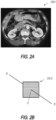
- scanner 22 may be a CT scanner configured to direct and receive X-rays along an imaging axis I-I, and generate imaging data 23ID including a plurality of two-dimensional cross-sectional X-ray images taken at one or more angles and/or positions relative to body 1. A representative cross-sectional X-ray image is depicted in FIG.
- external scanner 22 may include a magnetic resonance imaging device configured to use magnetic fields, radio waves, and field gradients to generate imaging data 23ID including a plurality of three-dimensional images.
- Location data 23LD may be used to locate imaging data 23ID in body 1 with respect to natural and/or artificial markers.
- an imaging plane I-I extends through origin point O and body axis B-B extending therethrough.
- Origin point O may be defined at the centroid of a vertebrae of body 1 (e.g., FIG. 2A ), allowing body axis B-B to coincide with a longitudinal axis extending through the spine of body 1, and provide a common point of reference in each macroscan.
- Artificial markers may alternatively be placed in or on body 1 to define the location of origin point O and/or body axis B-B.
- an artificial marker may be placed on exterior surface 2, inside of body cavity 4, and/or on bed 8; and include radiopaque elements shaped to define the location of point O and/or axis B-B in a cross-sectional X-ray image of body 1.
- Transceiver 26 may comprise any wired or wireless technology configured to output macroscan data 23.
- transceiver 26 may be configured to output data 23 and/or otherwise communicate with a transceiver 66 of controller 60 using any known data communication technology, including Bluetooth ® , fiber optic cables, Wi-Fi, and the like. If mapping component 20, navigation component 40, and controller 60 are all part of the same device, then transceiver 26 may simply be a direct or wired connection between the respective components of such a device.
- navigation component 40 is configured to perform microscans of body 1, and output microscan data 43. Numerous aspects of navigation component 40 are described. As depicted for example in FIGs. 4A-5 , navigation component 40 comprises an elongated shaft 41 steerable through body path 5 and an internal scanner or sensor 42 configured to perform one or more microscans as shaft 41 is moved along path 5. Navigation component 40 may further comprise: a magnetic field generator 44 configured to generate a magnetic field about path 5; a tracking sensor 50 configured to locate scanner 42 in the magnetic field; and a transceiver 46 configured to output microscan data 43. As shown in FIGs.
- microscan data 43 include imaging data 43ID (e.g., a wave energy image) generated from the microscan, and location data 43LD (e.g., the location of the wave energy image along axis P-P) generated when the microscan is performed.
- imaging data 43ID e.g., a wave energy image
- location data 43LD e.g., the location of the wave energy image along axis P-P
- Elongated shaft 41 of FIGs. 4A-B may include at least one channel 45 extending therethrough, and any number of articulating portions and/or steering mechanisms operable together with channel 45.
- An exemplary steering mechanism may comprise a handle attached to a proximal end of shaft 41, and a plurality of pull wires extending through shaft 41, wherein the wires are configured to articulate shaft 41 in response to a physical force applied to an actuator on the handle, as in U.S. Patent No. 9,380,930, issued July 5, 2016 .
- shaft 41 may include a plurality of electrically responsive articulation sections configured to articulate shaft 41 in response to a control signal from controller 60, as in U.S. Patent No. 8,517,924, issued August 27, 2013 .
- the control signal may be generated in response to a user input, such as the movement of a joystick or like input device, including those described in U.S. Provisional Patent Application No. 62/287,667, filed January 27, 2016 .
- Imaging data 43ID may include any number of two- or three-dimensional images generated by internal scanner 42 in any format, at any resolution, using any scanning medium.
- scanner 42 may be configured to generate imaging data 43ID including three-dimensional images generated with ultrasound or like techniques.
- the depth, quality, and/or resolution of imaging data 43ID may be different and/or greater than that of imaging data 23ID, as indicated by exemplary grid patterns depicted in FIGs. 2B and 6B respectively.
- An exemplary scanner 42 is depicted in FIG. 5 . As shown, scanner 42 may be disposed on a distal portion 41D of shaft 41, and include a plurality of imaging elements 47; a plurality of light sources 49; and a probe 52. Each element of exemplary scanner 42 is now described.
- the plurality of imaging elements 47 may be configured to generate a portion of imaging data 43ID.
- data 43ID may be generated continuously and/or when shaft 41 is moved along body path axis P-P.
- Imaging elements 47 may be operable to generate images of body 1 at one or more frequencies of the electromagnetic spectrum, including frequencies in and beyond the visible light range.
- image elements 47 may include digital camera circuits configured to generate two-dimensional graphic images (e.g., photographic, topographic, and the like) of the interior of body 1.
- the plurality of imaging elements 47 may be spaced apart annularly around an exterior surface of shaft 41 so that the resulting images may be combined to form a continuous panoramic graphical image of the interior of body path 5 and/or body cavity 4.
- Plurality of light sources 49 may comprise light emitting diodes configured to generate light at one or more wavelengths.
- Light sources 49 may be operable with imaging elements 47 (e.g., activated together) to provide illumination for imaging data 43ID.
- Light sources 49 may be limited to imaging purposes. For example, because tracking sensor 50 may be responsive to a magnetic field, as described below, navigation component 40 may be configured for use in the dark, i.e., without any navigational light, or in the presence of light that might challenge visibility, such as light generated by rapidly pulsed laser energy.
- plurality of light sources 49 may be configured to generate a photosensitive response from the interior surfaces of body 1.
- a photosensitive material may be delivered through lumen 45, body path 5 and/or body cavity 4, and then illuminated by light sources 49 at a wavelength configured to produce a photosensitive reaction with targeted tissues within path 4 and/or cavity 5.
- characteristics of this reaction e.g., density, intensity, size, etc.
- Probe 52 may be operable independent of or together with imaging elements 47 (e.g., activated together) to generate another portion of imaging data 43ID.
- probe 52 may be configured to direct a wave energy (e.g., light, sound, X-rays, etc.) toward the interior surfaces of body 1, receive a reflected portion of the wave energy, and generate imaging data 43ID including two-or three-dimensional wave energy images of body 1.
- Probe 52 of FIG. 4 may be an intravascular ultrasound (or "IVUS") probe including a plurality of forward-facing and/or side-facing transducers configured to direct and receive sound waves along path axis P-P and/or in other directions transverse therewith (e.g., FIG.
- probe 52 may include a laser scanner configured to discharge a laser energy (e.g., a pulsed or continuous laser beam) into body 1, receive a reflected portion of the laser energy, and generate imaging data 43ID including three-dimensional images of path 5 and/or cavity 4.
- a laser energy e.g., a pulsed or continuous laser beam
- Tracking sensor 50 may be operable with magnetic field generator 44 to generate location data 43LD, for example, each time at least one of the plurality of imaging elements 47 and/or probe 52 are activated.
- exemplary sensor 50 includes a housing mounted on distal portion 41D of shaft 41, and a sensor coil (not shown) mounted in the housing.
- Magnetic field generator 44 is shown in FIGs. 1 and 4A-B as a planar element with a plurality of field generation elements (not shown) that may be placed, for example, underneath a bed 8 supporting body 1 (e.g., as in FIG. 1 ), or directly underneath body 1 (e.g., as in FIGs. 4A-B ), and configured to generate a magnetic field (not shown) extending about body path 5.
- the coil in tracking sensor 50 may output, in real-time, location data 43LD including a continuous locator signal (e.g., an analog signal) responsive to the magnetic field produced by generator 44.
- a continuous locator signal e.g., an analog signal
- Transceiver 46 may comprise any wired or wireless technology configured to output microscan data 43.
- transceiver 46 may be configured to output data 43 and/or otherwise communicate with transceiver 66 of controller 60 using any known data communication technology, including Bluetooth ® , fiber optic cables, Wi-Fi, and the like.
- Transceiver 46 of FIGs. 4A-B is coupled to a proximal portion of shaft 41 and located outside of body 1. As shown, transceiver 46 is configured to receive microscan data 43 from internal scanner 42 via a wired connection, and transmit microscan data 43 to transceiver 66 via a wireless connection with controller 60.
- Controller 60 of FIG. 7 is configured to generate a pre-operative body information model 25 (e.g., FIG. 3 ) from macroscan data 23, operatively update model 25 with microscan data 43, and/or output portions of information model 25 in pre-operative or updated state, in real-time, as a navigation image 27 (e.g., FIG. 7 ).
- controller 60 may include: one or more processors 62; a memory 65 including computer-readable instructions 64 executable by one or more processors 62; a transceiver 66; sensor interface unit 68; localization unit 70; and a signal station 72.
- controller 60 may be organized in a single device, as shown in FIG. 7 , or distributed throughout system 10, each element being capable of reciprocal communication with the next, and/or the components 20 and 40, however arranged.
- One or more processors 62 may be part of controller 60, distributed throughout system 10, and/or located remotely from system 10 and placed in communication therewith. Processors 62 are configured to perform any computational function described herein responsive to computer-readable instructions 64.
- Memory 65 may include any technology configured to store instructions 64 as well as any other data and/or information described herein. Like processors 62, memory 65 also may be located anywhere relative to system 10.
- Transceiver 66 may comprise any wired or wireless technology configured to receive macroscan data 23 and microscan data 43.
- transceiver 46 may be configured to receive data 23 and 43, and/or otherwise communicate with transceiver 26 of navigation component 20 and transceiver 46 of navigation component 40 using any known data communication technology, including Bluetooth ® , fiber optic cables, Wi-Fi, and the like.
- Transceiver 66 may be located anywhere relative to system 10.
- Processor 60 may be configured to generate location data 43LD any time, such as whenever imaging dating 43ID is generated.
- sensor interface unit 68 e.g., FIG. 7
- sensor interface unit 68 may be configured to receive the locator signal from tracking sensor 50, and convert (e.g., condition, amplify, and/or digitize) the locator signal into a digital location signal including raw magnetic data.
- Localization unit 70 e.g., FIG. 7
- Signal station 72 is configured to output location data 43LD, for example, for display within navigation image 27.
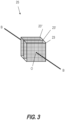
- Body information model 25 may be generated with controller 60 by combining two- or three-dimensional images within macroscan data 23 according to location data 23LD to define a three-dimensional data set or data mesh.
- macroscan data 23 may include a first cross-sectional data set 23', a second cross-sectional data set 23", and a third cross-sectional data set 23′′′ spaced apart at predetermined intervals along body axis B-B.
- First data set 23' may be generated by positioning external scanner 22 at a first location along axis B-B, generating imaging data (e.g., 23ID'), and associating location data (e.g., 23LD') therewith.
- External scanner 22 may then be moved to second and third positions on axis B-B to generate second data set 23" and third data set 23′′′.
- controller 60 is configured to generate the three-dimensional data set by combining (e.g., stitching) the images within data sets 23', 23", and 23′′′ along body axis B-B. Similar methods may be used to combine three-dimensional data sets.
- body information model 25 may be generated by another device and delivered to controller 60 without external scanner 22.
- information model 25 may be included with the patient's electronic medical records and delivered to processor 60 via transceiver 66.
- Body information model 25 also may be created with microscan data 43 using similar methods.
- Controller 60 may define at least a general representation of body cavity 4, body path 5, and path axis P-P in this three-dimensional data set. For example, controller 60 may automatically define the boundary conditions of body cavity 4 and body path 5, and/or plot body path axis P-P therethrough. To enhance this general representation of body 1, controller 60 is configured to operatively update (e.g., in real-time, during an operation) a pre-operative version of body information model 25 by correlating location data 43LD with location data 23LD at target locations in body 1, and combining imaging data 23ID with a correlated portion of imaging data 43ID at the target locations.
- operatively update e.g., in real-time, during an operation
- location data 43LD may be correlated with location 23LD by locating a portion of imaging data 43ID at a first location along path axis P-P, geometrically aligning (e.g., resizing, shifting, rotating, etc.) a boundary condition defined by imaging data 23ID at the first location with a boundary condition defined by imaging data 43ID at that location, and then repeating these steps at a plurality of second locations along path axis P-P.
- a diameter of body path 5 may, for example, be used as the boundary condition.
- Imaging data 23ID and 43ID may be combined using a variety of techniques.
- portions of imaging data 43ID are overlaid onto or stitched together with portions of imaging data 23ID at a plurality of locations along axis P-P.
- controller 60 may be configured to select a target location in pre-operative body information model 25, identify imaging data 23ID and 43ID associated with the target location, and overlay aspects of data 43ID onto data 23ID at that location.
- a cross-sectional image included in imaging data 43ID at the target location is overlaid onto a cross-sectional image included in imaging data 23ID at the same location or a three-dimensional image included in data 43ID is stitched together with a three-dimensional image included in data 23ID at the target location.
- Body information model 25 may be enhanced by combining imaging data 23ID with imaging data 43ID.
- imaging data 43ID may be generated at a higher resolution than imaging data 23ID, owing to the different capabilities of scanner 42 and its location within body 1, the resolution of body information model 25 may be increased when imaging data 23ID and imaging data 43ID are combined.
- controller 60 may be further configured to overlay graphical images captured by the plurality of imaging elements 47 onto representation of body cavity 4 and/or body path 5 in body information model 25, resulting in enhanced or even photo-realistic depictions of the interior surfaces cavity 4 and/or path 5.
- graphical images may aligned and oriented within body information model 25 (e.g., resized, shifted, rotated, etc.) according to location data 23LD and/or 43LD. If a photosensitive material has been delivered into body path 5, and activated by plurality of light sources 49, for example, then any resulting photosensitive response may thus be represented in body information model 25, allowing for identification and/or diagnosis of those responses. Other conditions may be identified and diagnosed using similar methods, with or without a photosensitive material.
- body information model 25 may be a data-rich environment that is far more detailed than would otherwise be possible with just external scanner 22 or internal scanner 42.
- controller 60 may be configured to output aspects of model 25 as a two- or three-dimensional navigation image 27. Any aspect of body information model 25 described herein may be represented in image 27.
- navigation image 27 is a three-dimensional representation that has been visually enhanced, for example, by adjusting contrast and color, adding boundary lines, creating a wireframe model, and truncating extraneous anatomy. Any graphical technique may be used. As shown in FIG.
- controller 60 may use location data 23LD and 43LD to output navigation image 27 as a three-dimensional representation of body 1 depicting external surface 2, entry point 3, interior cavity 4, body path 5, and body path axis P-P in relation to internal scanner 42.
- cavity 4 of FIG. 7 may be the interior of a kidney
- navigation image 27 may provide a three-dimensional representation depicting scanner 42 moving through a natural body path extending into the kidney through a urethra, bladder, and/or ureter.
- controller 60 may be configured to overlay microscan data 43 onto macroscan data 23, and iteratively define the boundaries of body path 5 and/or body cavity 4. These boundaries may then be displayed on navigation image 27 to provide, for example, a highly detailed two- or three-dimensional map of body 1.
- controller 60 of FIG. 7 may be configured to plot a course through body path 5, and/or display the course on navigation image 27, for example, as a two- or three-dimensional pathway.
- Image 27 may be configured to guide shaft 41 through body path 5 along this pathway.
- navigation image 27 may include graphical indicators (e.g., directional arrows) configured to guide scanner 42 through body path 5 along axis P-P.
- a user may guide scanner 42 into a specific portion of body cavity 4 (e.g., a calyx of a kidney) by, for example, manipulating an actuator on the handle of an endoscope so as to articulate and/or advance the distal end 41D of shaft 41 through a tortuous portion of body path 5, and/or around a tight corner inside of cavity 4, as shown by the movements between FIG. 4A and FIG. 4B .
- Direct visualization of body path 5 may be provided by imaging elements 47, but is not required.
- image 27 may be used to guide distal end 41D toward a kidney stone located in body cavity 4, even if the stone is located in a narrow calyx and surrounded by a turbid fluid; regardless of bio-impedance changes, respiratory patterns, or fluid status; and without reliance on a positional electrodes or visual images.
- Controller 60 may be configured to provide additional navigation and cue features to further guide distal end 41D, such as generating audio or tactile feedback signals.
- Controller 60 may be configured to identify one or more targeted objects or locations in body 1, and/or determine characteristics of said objects or locations.
- Navigation image 27 may allow for rotation and zoom, permitting optimal views of the targeted objects or locations; and/or the selection of particular objects or locations.
- controller 60 may allow a user to plan an operation with navigation image 27, and annotate image 27 during the operation, for example, by marking portions of body cavity 4 that have been treated.
- the wave energy generated by probe 52 may be utilized to identify kidney stones inside of body cavity 4, determine the location of each kidney stone in body information model 25, and ascertain characteristics of each stone (e.g., composition, density, fragility, and/or size).
- Controller 60 may be further configured to identify stones having a targeted characteristic, associate the targeted stones with one or more tags or icons in navigation image 27, determine whether a user has removed the targeted stones (or missed one), and/or validate that cavity 4 has been cleared of all the stones.
- Each targeted stone may, for example, be associated with a different tag or icon to facilitate rapid identification.
- These tags or icons may indicate a size of the stone, such as a maximum width of the stone.
- Controller 60 may be configured to compare the maximum width of each stone with a predetermined maximum size of a retrieval device (e.g., the maximum diameter of a retrieval basket or channel), and indicate whether each stone can removed with said device, allowing the user to determine whether additional treatment is required.
- a stone may be captured in a retrieval basket, sized to determine a maximum width, and associated with a tag or icon indicating whether the captured stone can be removed in said retrieval basket without further treatment.
- tags or icons may, for example, indicate whether the captured stone may be removed if released and recaptured to a lower profile orientation, and/or treated with laser energy to decrease the size of the capture stone.
- Similar techniques may be used to determine characteristics (e.g., a size, surface area, or volume) of body cavity 4 and/or body path 5, and associate cavity 4 and/or path 5 with said characteristics. For example, various natural markers within body cavity 4 and/or body path 5 may be associated with tags and icons in navigation image 27 to communication the respective volumes of cavity 4 and path 5.
- characteristics e.g., a size, surface area, or volume
- System 10 may include any combination of these aspects with any other aspects described herein, each possible combination being part of the present disclosure.
- controller 60 is configured to perform microscan sequences.
- the plurality of imaging elements 47, plurality of light sources 49, and probe 52 may be activated in a predetermined sequence, and localization unit 70 may generate location data 43LD each time these elements are activated in the predetermined sequence.
- system 10 may, for example, be switchable between: a first mode with a continuous activation rate corresponding with a desired refresh rate of image 27 (e.g., 60hz or 120Hz); a second mode with a pulsed and/or staggered activation rate corresponding with a desired imaging or treatment method (e.g., photosensitive reactions); and/or a third mode where microscan data 43 is automatically generated each time internal scanner 42 is moved a predetermined distance along body path axis P-P (e.g., ⁇ 1mm).
- a first mode with a continuous activation rate corresponding with a desired refresh rate of image 27 e.g., 60hz or 120Hz
- a second mode with a pulsed and/or staggered activation rate corresponding with a desired imaging or treatment method (e.g., photosensitive reactions)
- a third mode where microscan data 43 is automatically generated each time internal scanner 42 is moved a predetermined distance along body path axis P-P (e.g., ⁇ 1
- Magnetic field generator 44 is depicted as a planar element in FIGs. 1 and 4A-B , but may assume any shape, and include any number of field generation elements.
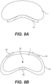
- an alternative magnetic field generator 144 is depicted in FIG. 8A as a flexible element that is directly attached (e.g., adhered) to a portion body 1 (e.g., the back) so as to provide a fixed frame of reference for tracking sensor 50, even if body 1 is moved during the time period between each macroscan and/or microscan.
- Generator 44 also may be formed integral with bed 8 ( FIG. 1 ), which also may provide a reference location for body 1.
- tracking sensor 50 is operable with additional and/or alternative tracking devices.
- sensor 50 may be operable with a sensor belt 244, depicted in FIG. 8B as being wrapped around body 1.
- belt 244 includes three external sensors 246, although any number of sensors may be provided.
- Belt 244 of FIG. 8B is wrapped around a medial-lateral axis of body 1 so that sensors 246 are arranged about body axis B-B of body 1 in a generally triangular formation.
- sensors 246 may generate location data 43LD for tracking sensor 250 as it moved through an interior diameter of belt 244.
- tracking sensor 250 includes an RFID sensor or antenna located on a distal portion of an elongated element, and sensors 246 are operable with the RFID sensor to generate location data 43LD when the elongated element is moved through belt 244.
- Belt 244 may have a narrow width (e.g., 2.54-7.62 cm (1-3 inches)); alternatively, belt 244 may be elongated to define a sleeve.
- belt 244 includes tension elements (e.g., elastic, buckles, etc.) configured to hold belt 244 in a fixed position relative to body 1.
- internal scanner 42 may include a shape-sensing mechanism configured to determine location data 43LD from the shape of shaft 41.
- the shape-sensing mechanism may be configured to measure the stress and deflection of elongated shaft 41 at various positions along its length, and determine location data 43LD therefrom independent of any temperature or loading applied to shaft 41.
- the shape-sensing mechanism may be included within an optical fiber extending within shaft 41, such as a Fiber Bragg Grating (FBG) fiber.
- FBG Fiber Bragg Grating
- controller 60 may be configured to steer shaft 41 at least partially through body path 5 and/or into body cavity 4 responsive to body information model 25, with or without navigation image 27.
- shaft 41 may include a plurality of electrically responsive articulation sections
- controller 60 may include a steering module 74 (shown in dotted lines on FIG. 4 ) configured to generate a steering signal responsive to a user input, such as the movement of a joystick in a proximal or distal direction and/or a confirmation as to location of body cavity 4.
- Steering module 74 may use the steering signal to selectively actuate the plurality of electrically responsive articulation sections of shaft 41.
- the user input need not be exact or precise.
- steering module 74 may be configured to automatically plot a precise course through a portion of body path 5 responsive to a generic user input (e.g., a forward joystick movement), and/or steer shaft 41 through body path 5 on that course without exact corrections from the user.
- a generic user input e.g., a forward joystick movement
- an exemplary method 300 may comprise: receiving macroscan data 23 (310); generating a pre-operative body information model 25 with macroscan data 23 (320); receiving microscan data 43 (330) during an operation; and updating the body information model by combining a portion of microscan data 43 with a correlated portion of macroscan data 23 (340).
- macroscan data 23 may include pre-diagnostic and/or pre-operative images taken in advance of an operation. Each image may be generated by external scanner 22.
- method 300 at 310 may further comprise: directing a wave energy (e.g., light, sound, X-rays, etc.) toward exterior surface 2 of body 1, receiving a reflected portion of the wave energy, and generating imaging data 23ID including wave energy images of body 1.
- the wave energy may be directed along imaging axis I-I, such that each wave energy image includes a cross-sectional image of body 1 (e.g., FIG. 2A ).
- Method step 310 may be repeated at a plurality of positions along body axis B-B of body 1.
- step 310 may comprise positioning external scanner 22 at a plurality of positions along a body axis B-B of body 1, generating macroscan data 23 including imaging data 23ID and location data 23LD at each of the plurality of positions, and outputting macroscan data 23 to controller 60.
- Method 300 at step 320 comprises generating a pre-operative body information model 25 with macroscan data 23.
- Body 1 may be moved after the macroscans are completed, such that method step 320 may occur anytime after method 310.
- method step 320 may comprise combining macroscan data 23 according to location data 23LD to define a three-dimensional data set.
- Step 320 may further comprise providing at least a general representation of body cavity 4, body path 5, and path axis P-P in this three-dimensional data set.
- body information model 25 may be generated by another device and deliver to controller 60 without external scanner 22, in which case, method 300 at steps 310 and 300 may comprise receiving model 25 with transceiver 66.
- method 300 may comprise receiving body information model 25 from a patient's electronic medical record, modifying aspects of model 25 as described herein, and/or updating the electronic medical record accordingly.
- Microscan data 43 may include two- or three-dimensional images taken during an operation. Each of these images may be generated by internal scanner 42.
- method 300 at step 330 may include: directing a wave energy (e.g., light, sound, X-rays, etc.) toward the interior surfaces of body 1, receiving a reflected portion of the wave energy, and generating imaging data 43ID including wave energy images of body 1.
- Each wave energy image may, for example, include a cross-sectional image of body path 5 (e.g., FIG. 6A ).
- Graphical images from imaging elements 47 may likewise may be included in imaging data 43ID.
- method step 330 may comprise positioning internal scanner 42 at a plurality of positions along path axis P-P, generating microscan data 43 including imaging data 43ID and location data 43LD at each of the plurality of positions, and outputting data 43.
- Method step 340 of FIG. 9A comprises updating the pre-operative body information model 25 by combining a portion of microscan data 43 with a correlated portion of macroscan data 23.
- information model 25 is updated in real-time as internal scanner 22 is moved through body 1.
- step 340 may include: correlating location data 23LD with location data 43LD at a target location in body 1, and combining imaging data 23ID with imaging data 43ID at the target location.
- Location data 23LD and 43LD may be correlated in body information model 25 using any technique. Any means of combining macroscan data 23 with microscan data 43 may likewise be employed in step 330.
- a two-dimensional cross-sectional ultrasound image included in imaging data 43ID may be overlaid onto a two-dimensional cross-sectional X-ray image included in imaging data 23ID to update the boundary conditions of body cavity 4 and/or body path 5.
- portions of a three-dimensional image in data 23ID may be overlaid with a two-dimensional image in data 4310, or stitched together with portions of a three-dimensional image in data 23ID.
- Additional steps for method 300 are depicted in FIG. 9B as comprising: outputting a portion of body information model 25 as navigation image 27 (350), and guiding shaft 41 through body 1 responsive to or as function of image 27 (360).
- Navigation image 27 may be a two- or three-dimensional image generated with any technique.
- method step 350 may comprise graphically rendering the three-dimensional data set included in body information model 25.
- Navigation image 27 may be enhanced in step 350.
- step 350 may comprise associating the boundary conditions of body cavity 4 and/or body path 5 with a particular color or line weight.
- step 350 may further comprise superimposing graphical images from imaging elements 47 onto these boundary conditions.
- Method 300 at step 360 may include guiding steps.
- a plurality of body paths 5 may be defined through body 1, such that method step 360 includes obtaining user input regarding an optimal path 5.
- Step 360 may further comprise generating one or more graphical indictors (e.g., directional arrows) configured to guide elongated shaft 41 through path 5. Additional navigation and cue features may be provided at step 360, such as generating audio or tactile feedback signals. Additional targets in body 1 may be identified in method 300.
- step 360 may further include identifying one or more targeted objects or locations in body cavity 4, determining characteristics of said one or more objects or locations, and guiding the distal end 41D of elongated shaft 41 towards a particular object or location based on its characteristics.
- additional method steps may be provided with respect to any aspect of system 10 described herein.
Landscapes
- Health & Medical Sciences (AREA)
- Life Sciences & Earth Sciences (AREA)
- Surgery (AREA)
- Engineering & Computer Science (AREA)
- Public Health (AREA)
- General Health & Medical Sciences (AREA)
- Animal Behavior & Ethology (AREA)
- Veterinary Medicine (AREA)
- Biomedical Technology (AREA)
- Heart & Thoracic Surgery (AREA)
- Medical Informatics (AREA)
- Molecular Biology (AREA)
- Nuclear Medicine, Radiotherapy & Molecular Imaging (AREA)
- Pathology (AREA)
- Biophysics (AREA)
- Physics & Mathematics (AREA)
- Radiology & Medical Imaging (AREA)
- Optics & Photonics (AREA)
- Signal Processing (AREA)
- Robotics (AREA)
- Human Computer Interaction (AREA)
- Computer Vision & Pattern Recognition (AREA)
- Multimedia (AREA)
- Oral & Maxillofacial Surgery (AREA)
- Gynecology & Obstetrics (AREA)
- Urology & Nephrology (AREA)
- Endoscopes (AREA)
- Ultra Sonic Daignosis Equipment (AREA)
Description
- This patent application claims the benefit of priority under 35 U.S.C. § 119 to
U.S. Provisional Patent Application No. 62/420,891, filed November 11, 2016 - Aspects of the present disclosure generally relate to medical devices and operations. Particular aspects relate to guidance systems and associated methods.
- Elongated devices are commonly used to access remote regions and cavities of the body for diagnostic, surgical, and/or therapeutic purposes. For example, endoscopes may use naturally formed lumens or orifices, and/or surgical incisions to access the colon, esophagus, stomach, urethra, bladder, ureter, kidneys, lungs, bronchi, uterus, and other organs; and catheters may use the circulatory system as pathways to access treatment sites near the heart, or the urinary canal to access urinary regions. These elongated devices may be introduced into the body through a natural body path, such as large artery, including those found in the groin or in the neck. The same device also may be introduced through artificial paths formed in the body, such as a tunnel formed by a tunneling tool.
- Navigation through some body paths requires the elongated device to be passed through ever-narrowing diameters until a distal end of the device reaches an operative site inside the body. Locating the distal end at the operative site can be challenging. In some instances, a fluoroscope may be employed to guide the distal end through the body in one plane of movement. Because X-rays are applied externally, in a single imaging plane, they often cannot account for localized aspects of body paths, especially paths extending deep into the body. Additional sensing technologies are needed to guide medical devices through a greater range of body paths, and reduce the risks associated with such navigation. Aspects of the devices, methods, and systems described herein are provided to address these issues.
- Document
WO 2016/018646 A1 discloses method which comprises navigating a patient's anatomy with a medical instrument, the instrument comprising a sensing tool. The method further includes correlating a position of the instrument with a model of the patient's anatomy. The method further includes, while navigating the patient's anatomy, updating the model based on data obtained by the sensing tool. - Document
EP 3 304 423 A1 describes a method and system for scene parsing and model fusion in laparoscopic and endoscopic 2D/2.5D image data. A current frame of an intra-operative image stream including a 2D image channel and a 2.5D depth channel is received. A 3D pre-operative model of a target organ segmented in pre-operative 3D medical image data is fused to the current frame of the intra-operative image stream. Semantic label information is propagated from the pre-operative 3D medical image data to each of a plurality of pixels in the current frame of the intra-operative image stream based on the fused pre-operative 3D model of the target organ, resulting in a rendered label map for the current frame of the intra-operative image stream. A semantic classifier is trained based on the rendered label map for the current frame of the intra-operative image stream. - Document
EP 3 367 915 A1 describes a method for performing a percutaneous operation on a patient to remove an object from a cavity within the patient. The method includes advancing a first alignment sensor into the cavity through a patient lumen. The first alignment sensor provides its position and orientation in free space in real time. The alignment sensor is manipulated until it is located in proximity to the object. A percutaneous opening is made in the patient with a surgical tool, where the surgical tool includes a second alignment sensor that provides the position and orientation of the surgical tool in free space in real time. The surgical tool is directed towards the object using data provided by both the first and the second alignment sensors. - Document
EP 3 366 254 A1 describes systems, devices, and methods for navigating a tool inside a luminal network. An exemplary method includes receiving image data of a patient's chest, identifying the patient's lungs, determining locations of a luminal network in the patient's lungs, identifying a target location in the patient's lungs, generating a pathway to the target location, generating a three-dimensional (3D) model of the patient's lungs, the 3D model showing the luminal network in the patient's lungs and the pathway to the target location, determining a location of a tool based on an electromagnetic (EM) sensor included in the tool as the tool is navigated within the patient's chest, displaying a view of the 3D model showing the determined location of the tool, receiving cone beam computed tomography (CBCT) image data of the patient's chest, updating the 3D model based on the CBCT image data, and displaying a view of the updated 3D model. - The invention is defined in appended claim 1. Further aspects and preferred embodiments are defined in the dependent claims. Aspects, embodiments and examples of the present disclosure which do not fall under the scope of the appended claims are merely provided for illustrative purposes. Surgical methods described herein do not form part of the claimed invention. Aspects of the present disclosure relate to guidance devices, systems, and methods. Numerous aspects of the present disclosure are now described.
- One aspect of the present disclosure is a method comprising: receiving macroscan data including first images of a body and first location data associated with each first image; combining the first images according to the first location data to generate a body information model; positioning a navigation component in the body; generating microscan data with the navigation component, the microscan data including second images of the body and second location data associated with each second image; correlating the first location data with the second location data at a target location in the body information model; and/or modifying the body information model by combining the first images with the second images at the target location.
- According to this aspect, the navigation component may include an elongated shaft and an internal scanner located on a distal portion of the elongated shaft, and the method may comprise positioning the internal scanner in the body, and generating the microscan data with the internal scanner. The internal scanner may include a probe configured to generate wave energy images of the body and the second images may include the wave energy images, the method further comprising generating the wave energy images with the probe. The probe may include one or more ultrasound transducers configured to generate ultrasound images of the body, and generating the wave energy images may comprise generating ultrasound images with the one or more ultrasound transducers. The probe may include one or more laser sources configured to generate laser images of the body, and generating the wave energy images may comprise generating laser images with the one or more laser sources.
- In some aspects, the internal scanner may include a plurality of imaging elements configured to generate graphical images and the second images may include the graphical images, the method further comprising generating the graphical images at one or more frequencies of the electromagnetic spectrum with the plurality of imaging elements. Generating the graphical images may comprise generating the graphical images in a visual light range. The internal scanner includes a plurality of light sources, and the method may further comprise operating the plurality of light sources independent of or together with the plurality of imaging elements. Generating the microscan data may include generating second images and location data according to a predetermined sequence. For example, the second images may be generated at a rate of 60Hz or greater in the predetermined sequence.
- In other aspects, the navigation component may include an elongated shaft, and positioning a navigation component in the body may comprise moving a distal portion of the elongated shaft through the body. For example, the distal portion of the elongated shaft may include a tracking sensor responsive to a magnetic field, and generating second location data may comprise moving the sensor in the field.
- Another aspect of the present disclosure is a method comprising: receiving macroscan data prior to an operation; generating a body information model from the macroscan data; positioning a navigation component in the body during the operation; generating microscan data with the navigation component; correlating a location in the macroscan data with a location in the microscan data in the body information model; and/or modifying the body information model by combining an image in the microscan data with an image in the macroscan data.
- According to this aspect, the method may comprise outputting a portion of the body information model as a navigation image. For example, the method may comprise: identifying a path through the body in the navigation image; identifying a location of the navigation component in the navigation image; and guiding the navigation component along the path in the navigation image. The method may further comprise: locating objects in the body relative to the path; and guiding the navigation component to the located objects. In some aspects, the method includes determining characteristics of the located objects. The method also may include: selecting one of the located objects based on its characteristics; performing a treatment on the selected object; and modifying the body information model to indicate that the selected object has been treated.
- Yet another aspect of the present disclosure is a method comprising: receiving macroscan data prior to an operation, the macroscan data including first images of a body and first location data associated with each first image; combining the first images according to the first location data to generate a body information model; positioning a navigation component in the body during the operation; generating microscan data with the navigation component, the microscan data including second images of the body and second location data associated with each second image; correlating the first location data with the second location data at a target location in the body information model; modifying the body information model by combining the first images with the second images at the target location; outputting a portion of the body information model as a navigation image; identifying a path through the body in the navigation image; identifying a location of the navigation component in the navigation image; and/or guiding the navigation component along the path in the navigation image.
- It may be understood that both the foregoing summary and the following detailed descriptions are exemplary and explanatory only, neither being restrictive of the inventions claimed below.
- The accompanying drawings are incorporated in and constitute a part of this specification. These drawings illustrate aspects of the present disclosure that, together with the written descriptions herein, serve to explain this disclosure. Each drawing depicts one or more aspects of this disclosure as follows:
-
FIG. 1 depicts an exemplary mapping component of a system. -
FIG. 2A depicts exemplary aspects of macroscan data. -
FIG. 2B depicts additional exemplary aspects of the microscan data. -
FIG. 3 depicts aspects of an exemplary body information model. -
FIG. 4A depicts aspects of an exemplary navigation component at a first location in a body. -
FIG. 4B depicts the navigation component ofFIG. 2A at a second location in a body. -
FIG. 5 depicts an exemplary configuration of the navigation component depicted inFIGs. 4A-B . -
FIG. 6A depicts exemplary aspects of microscan data. -
FIG. 6B depicts additional exemplary aspects of microscan data. -
FIG. 7 depicts an exemplary controller. -
FIG. 8A depicts an exemplary navigation device. -
FIG. 8B depicts another exemplary navigation device. -
FIG. 9A depicts an exemplary method. -
FIG. 9B depicts another exemplary method. - Aspects of the present disclosure are now described with reference to exemplary guidance systems and associated methods. Some aspects are described with reference to operations where an elongated device is guided through a body path until a distal end of the elongated body is located in a body cavity (or other target site in a body). For example, an endoscope may include an elongated body that is guided through a natural body path including a urethra, bladder, and/or ureter until a distal end of endoscope is located in an interior cavity of a kidney. References to a particular type of operation or procedure, such as medical; body path, such as natural or artificial; or body cavity, such as the interior cavity of a kidney, are provided for convenience and not intended to limit the present disclosure unless claimed. Accordingly, the concepts described herein may be utilized for any analogous device or method - medical or otherwise, kidney-specific or not.
- Numerous axes are described. Each axis may be transverse, or even perpendicular, with the next so as to establish a Cartesian coordinate system with an origin point O (or O'). One axis may extend along a longitudinal axis extending through an origin point defined within an element or body path. The directional terms "proximal" and "distal," and their respective initials "P" and "D," may be used to describe relative components and features in relation to these axes. Proximal refers to a position closer to the exterior of the body or a user, whereas distal refers to a position closer to the interior of the body or further away from the user. Appending the initials "P" or "D" to an element number signifies a proximal or distal location, and appending P or D to an arrow in a figure signifies a proximal or distal direction along one or more axes. The term "elongated" may be used to describe any aspect extending proximally or distally along any axis. Unless claimed, these terms are provided for convenience and not intended to limit the present disclosure to a particular location, direction, or orientation.
- As used herein, the terms "comprises," "comprising," or like variation, are intended to cover a non-exclusive inclusion, such that a device or method that comprises a list of elements does not include only those elements, but may include other elements not expressly listed or inherent thereto. Unless stated otherwise, the term "exemplary" is used in the sense of "example" rather than "ideal." Conversely, the terms "consists of" and "consisting of" are intended to cover an exclusive inclusion, such that a device or method that consists of a list of elements includes only those elements. As used herein, terms such as "about," "substantially," "approximately," or like variations, may indicate a range of values within +/- 5% of a stated value.
- Aspects of the present disclosure pertain to an
exemplary guidance system 10, examples of which are depicted inFIGs. 1-8B with reference to an exemplary body 1. Body 1 may be a patient's body (e.g., a human body) or a portion thereof. InFIG. 1 , for example, body 1 is depicted as a medial-lateral cross-section of a human torso including: anexterior surface 2; an entry point 3 onsurface 2; a body cavity 4; and abody path 5 extending between entry point 3 and cavity 4. A body axis B-B extends through an origin point O in body 1 (e.g.,FIG. 1 ), and a body path P-P extends through an origin point O' in body path 5 (e.g.,FIGs. 4A-B ). -
System 10 may include amapping component 20 configured to perform macroscans of body 1 (e.g.,FIG. 1 ) and output macroscan data 23 (e.g.,FIGs. 2A-B ). Thesystem 10 includes anavigation component 40 configured to perform microscans of body 1 (e.g.,FIGs. 4A-5 ) and output microscan data 43 (e.g.,FIGs. 6A-B ); and a controller 60 (e.g.,FIG. 7 ) configured to generate a pre-operative body information model 25 (e.g.,FIG. 3 ) frommacroscan data 23, operatively updateinformation model 25 withmicroscan data 43, and/or output portions ofmodel 25 as a navigation image 27 (e.g.,FIG. 7 ). The terms "macroscan(s)" and "microscan(s)" are utilized herein to describe aspects ofsystem 10. In this application, a macroscan may be obtained from an externally-applied scanning medium (e.g., X-rays from a CT scanner), while a microscan may be obtained from an internally-applied scanning medium (e.g., sound waves from a transducer). -
Mapping component 20 is configured to perform macroscans of body 1, andoutput macroscan data 23. Anexemplary mapping component 20 is depicted inFIG. 1 as comprising anexternal scanner 22 configured to take one or more macroscans of body 1, and atransmitter 26 configured tooutput macroscan data 23. As shown inFIGs. 2A-B ,macroscan data 23 include: imaging data 23ID (e.g., a wave energy image) generated from the macroscan; and location data 23LD (.e.g., the location of the wave energy image along body axis B-B) generated when the macroscan is performed. - Imaging data 23ID may include any number of two- or three-dimensional images generated by
external scanner 22 in any format, at any resolution, using any scanning medium. For example,scanner 22 may be configured to direct a wave energy (e.g., light, sound, X-rays, etc.) towardexterior surface 2 of body 1, receive a reflected portion of the wave energy, and generate imaging data 23ID including wave energy images of body 1. In some aspects,scanner 22 may be a CT scanner configured to direct and receive X-rays along an imaging axis I-I, and generate imaging data 23ID including a plurality of two-dimensional cross-sectional X-ray images taken at one or more angles and/or positions relative to body 1. A representative cross-sectional X-ray image is depicted inFIG. 2A as imaging data 23ID generated by a CT scanner. Similar images may be created with other wave energies. In other aspects,external scanner 22 may include a magnetic resonance imaging device configured to use magnetic fields, radio waves, and field gradients to generate imaging data 23ID including a plurality of three-dimensional images. - Location data 23LD may be used to locate imaging data 23ID in body 1 with respect to natural and/or artificial markers. In
FIG. 1 , an imaging plane I-I extends through origin point O and body axis B-B extending therethrough. Origin point O may be defined at the centroid of a vertebrae of body 1 (e.g.,FIG. 2A ), allowing body axis B-B to coincide with a longitudinal axis extending through the spine of body 1, and provide a common point of reference in each macroscan. Artificial markers may alternatively be placed in or on body 1 to define the location of origin point O and/or body axis B-B. For example, an artificial marker may be placed onexterior surface 2, inside of body cavity 4, and/or onbed 8; and include radiopaque elements shaped to define the location of point O and/or axis B-B in a cross-sectional X-ray image of body 1. -
Transceiver 26 may comprise any wired or wireless technology configured tooutput macroscan data 23. For example,transceiver 26 may be configured tooutput data 23 and/or otherwise communicate with atransceiver 66 ofcontroller 60 using any known data communication technology, including Bluetooth®, fiber optic cables, Wi-Fi, and the like. Ifmapping component 20,navigation component 40, andcontroller 60 are all part of the same device, then transceiver 26 may simply be a direct or wired connection between the respective components of such a device. - With reference to
FIG. 4A ,navigation component 40 is configured to perform microscans of body 1, andoutput microscan data 43. Numerous aspects ofnavigation component 40 are described. As depicted for example inFIGs. 4A-5 ,navigation component 40 comprises anelongated shaft 41 steerable throughbody path 5 and an internal scanner orsensor 42 configured to perform one or more microscans asshaft 41 is moved alongpath 5.Navigation component 40 may further comprise: amagnetic field generator 44 configured to generate a magnetic field aboutpath 5; a trackingsensor 50 configured to locatescanner 42 in the magnetic field; and atransceiver 46 configured tooutput microscan data 43. As shown inFIGs. 6A-B ,microscan data 43 include imaging data 43ID (e.g., a wave energy image) generated from the microscan, and location data 43LD (e.g., the location of the wave energy image along axis P-P) generated when the microscan is performed. -
Elongated shaft 41 ofFIGs. 4A-B may include at least onechannel 45 extending therethrough, and any number of articulating portions and/or steering mechanisms operable together withchannel 45. An exemplary steering mechanism may comprise a handle attached to a proximal end ofshaft 41, and a plurality of pull wires extending throughshaft 41, wherein the wires are configured to articulateshaft 41 in response to a physical force applied to an actuator on the handle, as inU.S. Patent No. 9,380,930, issued July 5, 2016 shaft 41 may include a plurality of electrically responsive articulation sections configured to articulateshaft 41 in response to a control signal fromcontroller 60, as inU.S. Patent No. 8,517,924, issued August 27, 2013 . For example, the control signal may be generated in response to a user input, such as the movement of a joystick or like input device, including those described inU.S. Provisional Patent Application No. 62/287,667, filed January 27, 2016 - Imaging data 43ID may include any number of two- or three-dimensional images generated by
internal scanner 42 in any format, at any resolution, using any scanning medium. For example,scanner 42 may be configured to generate imaging data 43ID including three-dimensional images generated with ultrasound or like techniques. The depth, quality, and/or resolution of imaging data 43ID may be different and/or greater than that of imaging data 23ID, as indicated by exemplary grid patterns depicted inFIGs. 2B and6B respectively. Anexemplary scanner 42 is depicted inFIG. 5 . As shown,scanner 42 may be disposed on adistal portion 41D ofshaft 41, and include a plurality ofimaging elements 47; a plurality oflight sources 49; and aprobe 52. Each element ofexemplary scanner 42 is now described. - The plurality of
imaging elements 47 may be configured to generate a portion of imaging data 43ID. For example, data 43ID may be generated continuously and/or whenshaft 41 is moved along body path axis P-P.Imaging elements 47 may be operable to generate images of body 1 at one or more frequencies of the electromagnetic spectrum, including frequencies in and beyond the visible light range. As shown inFIG. 5 ,image elements 47 may include digital camera circuits configured to generate two-dimensional graphic images (e.g., photographic, topographic, and the like) of the interior of body 1. For example, the plurality ofimaging elements 47 may be spaced apart annularly around an exterior surface ofshaft 41 so that the resulting images may be combined to form a continuous panoramic graphical image of the interior ofbody path 5 and/or body cavity 4. - Plurality of
light sources 49 may comprise light emitting diodes configured to generate light at one or more wavelengths.Light sources 49 may be operable with imaging elements 47 (e.g., activated together) to provide illumination for imaging data 43ID.Light sources 49 may be limited to imaging purposes. For example, because trackingsensor 50 may be responsive to a magnetic field, as described below,navigation component 40 may be configured for use in the dark, i.e., without any navigational light, or in the presence of light that might challenge visibility, such as light generated by rapidly pulsed laser energy. In some aspects, plurality oflight sources 49 may be configured to generate a photosensitive response from the interior surfaces of body 1. For example, a photosensitive material may be delivered throughlumen 45,body path 5 and/or body cavity 4, and then illuminated bylight sources 49 at a wavelength configured to produce a photosensitive reaction with targeted tissues within path 4 and/orcavity 5. In some aspects, characteristics of this reaction (e.g., density, intensity, size, etc.) may be captured by imagingelements 47, output inmicroscan data 43 as imaging data 43ID, and/or processed bycontroller 60. -
Probe 52 may be operable independent of or together with imaging elements 47 (e.g., activated together) to generate another portion of imaging data 43ID. For example, probe 52 may be configured to direct a wave energy (e.g., light, sound, X-rays, etc.) toward the interior surfaces of body 1, receive a reflected portion of the wave energy, and generate imaging data 43ID including two-or three-dimensional wave energy images of body 1. Probe 52 ofFIG. 4 , for example, may be an intravascular ultrasound (or "IVUS") probe including a plurality of forward-facing and/or side-facing transducers configured to direct and receive sound waves along path axis P-P and/or in other directions transverse therewith (e.g.,FIG. 4A ), and generate imaging data 43ID including a plurality of two-dimensional cross-sectional ultrasound images (e.g.,FIG. 6A ). A representative IVUS ultrasound image ofbody path 5 is depicted inFIG. 6A , for example, as an axial ultrasound image generated from an IVUS probe. In other aspects,probe 52 may include a laser scanner configured to discharge a laser energy (e.g., a pulsed or continuous laser beam) into body 1, receive a reflected portion of the laser energy, and generate imaging data 43ID including three-dimensional images ofpath 5 and/or cavity 4. -
Tracking sensor 50 may be operable withmagnetic field generator 44 to generate location data 43LD, for example, each time at least one of the plurality ofimaging elements 47 and/or probe 52 are activated. InFIG. 5 ,exemplary sensor 50 includes a housing mounted ondistal portion 41D ofshaft 41, and a sensor coil (not shown) mounted in the housing.Magnetic field generator 44 is shown inFIGs. 1 and4A-B as a planar element with a plurality of field generation elements (not shown) that may be placed, for example, underneath abed 8 supporting body 1 (e.g., as inFIG. 1 ), or directly underneath body 1 (e.g., as inFIGs. 4A-B ), and configured to generate a magnetic field (not shown) extending aboutbody path 5. The coil in trackingsensor 50 may output, in real-time, location data 43LD including a continuous locator signal (e.g., an analog signal) responsive to the magnetic field produced bygenerator 44. -
Transceiver 46 may comprise any wired or wireless technology configured tooutput microscan data 43. For example,transceiver 46 may be configured tooutput data 43 and/or otherwise communicate withtransceiver 66 ofcontroller 60 using any known data communication technology, including Bluetooth®, fiber optic cables, Wi-Fi, and the like.Transceiver 46 ofFIGs. 4A-B , for example, is coupled to a proximal portion ofshaft 41 and located outside of body 1. As shown,transceiver 46 is configured to receivemicroscan data 43 frominternal scanner 42 via a wired connection, and transmitmicroscan data 43 totransceiver 66 via a wireless connection withcontroller 60. -
Controller 60 ofFIG. 7 is configured to generate a pre-operative body information model 25 (e.g.,FIG. 3 ) frommacroscan data 23, operatively updatemodel 25 withmicroscan data 43, and/or output portions ofinformation model 25 in pre-operative or updated state, in real-time, as a navigation image 27 (e.g.,FIG. 7 ). Accordingly,controller 60 may include: one ormore processors 62; amemory 65 including computer-readable instructions 64 executable by one ormore processors 62; atransceiver 66;sensor interface unit 68;localization unit 70; and asignal station 72. - These elements of
controller 60 may be organized in a single device, as shown inFIG. 7 , or distributed throughoutsystem 10, each element being capable of reciprocal communication with the next, and/or thecomponents more processors 62, for example, may be part ofcontroller 60, distributed throughoutsystem 10, and/or located remotely fromsystem 10 and placed in communication therewith.Processors 62 are configured to perform any computational function described herein responsive to computer-readable instructions 64.Memory 65 may include any technology configured to storeinstructions 64 as well as any other data and/or information described herein. Likeprocessors 62,memory 65 also may be located anywhere relative tosystem 10. -
Transceiver 66 may comprise any wired or wireless technology configured to receivemacroscan data 23 andmicroscan data 43. For example,transceiver 46 may be configured to receivedata transceiver 26 ofnavigation component 20 andtransceiver 46 ofnavigation component 40 using any known data communication technology, including Bluetooth®, fiber optic cables, Wi-Fi, and the like.Transceiver 66 may be located anywhere relative tosystem 10. -
Processor 60 may be configured to generate location data 43LD any time, such as whenever imaging dating 43ID is generated. For example, sensor interface unit 68 (e.g.,FIG. 7 ) may be configured to receive the locator signal from trackingsensor 50, and convert (e.g., condition, amplify, and/or digitize) the locator signal into a digital location signal including raw magnetic data. Localization unit 70 (e.g.,FIG. 7 ) may be configured to receive the digital location signal, and generate instantaneous location data 43LD based on the raw magnetic data, each time at least when one of the plurality ofimaging elements 47 and/or probe 52 are activated.Signal station 72 is configured to output location data 43LD, for example, for display withinnavigation image 27. -
Body information model 25 may be generated withcontroller 60 by combining two- or three-dimensional images withinmacroscan data 23 according to location data 23LD to define a three-dimensional data set or data mesh. For example, as shown inFIG. 3 ,macroscan data 23 may include a first cross-sectional data set 23', a second cross-sectional data set 23", and a third cross-sectional data set 23‴ spaced apart at predetermined intervals along body axis B-B. First data set 23' may be generated by positioningexternal scanner 22 at a first location along axis B-B, generating imaging data (e.g., 23ID'), and associating location data (e.g., 23LD') therewith.External scanner 22 may then be moved to second and third positions on axis B-B to generate second data set 23" and third data set 23‴. In this example,controller 60 is configured to generate the three-dimensional data set by combining (e.g., stitching) the images withindata sets 23', 23", and 23‴ along body axis B-B. Similar methods may be used to combine three-dimensional data sets. - In other aspects,
body information model 25 may be generated by another device and delivered tocontroller 60 withoutexternal scanner 22. For example,information model 25 may be included with the patient's electronic medical records and delivered toprocessor 60 viatransceiver 66.Body information model 25 also may be created withmicroscan data 43 using similar methods. -
Controller 60 may define at least a general representation of body cavity 4,body path 5, and path axis P-P in this three-dimensional data set. For example,controller 60 may automatically define the boundary conditions of body cavity 4 andbody path 5, and/or plot body path axis P-P therethrough. To enhance this general representation of body 1,controller 60 is configured to operatively update (e.g., in real-time, during an operation) a pre-operative version ofbody information model 25 by correlating location data 43LD with location data 23LD at target locations in body 1, and combining imaging data 23ID with a correlated portion of imaging data 43ID at the target locations. For example, because body path axis P-P is defined inmodel 25, location data 43LD may be correlated with location 23LD by locating a portion of imaging data 43ID at a first location along path axis P-P, geometrically aligning (e.g., resizing, shifting, rotating, etc.) a boundary condition defined by imaging data 23ID at the first location with a boundary condition defined by imaging data 43ID at that location, and then repeating these steps at a plurality of second locations along path axis P-P. A diameter ofbody path 5 may, for example, be used as the boundary condition. - Imaging data 23ID and 43ID may be combined using a variety of techniques. In one aspect, portions of imaging data 43ID are overlaid onto or stitched together with portions of imaging data 23ID at a plurality of locations along axis P-P. For example,
controller 60 may be configured to select a target location in pre-operativebody information model 25, identify imaging data 23ID and 43ID associated with the target location, and overlay aspects of data 43ID onto data 23ID at that location. In accordance with the invention, a cross-sectional image included in imaging data 43ID at the target location is overlaid onto a cross-sectional image included in imaging data 23ID at the same location or a three-dimensional image included in data 43ID is stitched together with a three-dimensional image included in data 23ID at the target location. -
Body information model 25 may be enhanced by combining imaging data 23ID with imaging data 43ID. For example, because imaging data 43ID may be generated at a higher resolution than imaging data 23ID, owing to the different capabilities ofscanner 42 and its location within body 1, the resolution ofbody information model 25 may be increased when imaging data 23ID and imaging data 43ID are combined. To provide even more detail,controller 60 may be further configured to overlay graphical images captured by the plurality ofimaging elements 47 onto representation of body cavity 4 and/orbody path 5 inbody information model 25, resulting in enhanced or even photo-realistic depictions of the interior surfaces cavity 4 and/orpath 5. These graphical images may aligned and oriented within body information model 25 (e.g., resized, shifted, rotated, etc.) according to location data 23LD and/or 43LD. If a photosensitive material has been delivered intobody path 5, and activated by plurality oflight sources 49, for example, then any resulting photosensitive response may thus be represented inbody information model 25, allowing for identification and/or diagnosis of those responses. Other conditions may be identified and diagnosed using similar methods, with or without a photosensitive material. - When generated by
controller 60 according to these aspects,body information model 25 may be a data-rich environment that is far more detailed than would otherwise be possible with justexternal scanner 22 orinternal scanner 42. To further leverage the capabilities of this environment,controller 60 may be configured to output aspects ofmodel 25 as a two- or three-dimensional navigation image 27. Any aspect ofbody information model 25 described herein may be represented inimage 27. For example, inFIG. 7 ,navigation image 27 is a three-dimensional representation that has been visually enhanced, for example, by adjusting contrast and color, adding boundary lines, creating a wireframe model, and truncating extraneous anatomy. Any graphical technique may be used. As shown inFIG. 7 , for example,controller 60 may use location data 23LD and 43LD tooutput navigation image 27 as a three-dimensional representation of body 1 depictingexternal surface 2, entry point 3, interior cavity 4,body path 5, and body path axis P-P in relation tointernal scanner 42. For example, cavity 4 ofFIG. 7 may be the interior of a kidney, andnavigation image 27 may provide a three-dimensionalrepresentation depicting scanner 42 moving through a natural body path extending into the kidney through a urethra, bladder, and/or ureter. - Whether two- or three-dimensional, numerous aspects of
navigation image 27 may be realized insystem 10. For example,controller 60 may be configured tooverlay microscan data 43 ontomacroscan data 23, and iteratively define the boundaries ofbody path 5 and/or body cavity 4. These boundaries may then be displayed onnavigation image 27 to provide, for example, a highly detailed two- or three-dimensional map of body 1. With reference to these boundaries,controller 60 ofFIG. 7 may be configured to plot a course throughbody path 5, and/or display the course onnavigation image 27, for example, as a two- or three-dimensional pathway.Image 27 may be configured to guideshaft 41 throughbody path 5 along this pathway. For example, because the location ofscanner 42 in body 1 may be determined from location data 43ID,navigation image 27 may include graphical indicators (e.g., directional arrows) configured to guidescanner 42 throughbody path 5 along axis P-P. - Responsive to
navigation image 27, a user may guidescanner 42 into a specific portion of body cavity 4 (e.g., a calyx of a kidney) by, for example, manipulating an actuator on the handle of an endoscope so as to articulate and/or advance thedistal end 41D ofshaft 41 through a tortuous portion ofbody path 5, and/or around a tight corner inside of cavity 4, as shown by the movements betweenFIG. 4A andFIG. 4B . Direct visualization ofbody path 5 may be provided byimaging elements 47, but is not required. For example,image 27 may be used to guidedistal end 41D toward a kidney stone located in body cavity 4, even if the stone is located in a narrow calyx and surrounded by a turbid fluid; regardless of bio-impedance changes, respiratory patterns, or fluid status; and without reliance on a positional electrodes or visual images.Controller 60 may be configured to provide additional navigation and cue features to further guidedistal end 41D, such as generating audio or tactile feedback signals. -
Controller 60 may be configured to identify one or more targeted objects or locations in body 1, and/or determine characteristics of said objects or locations.Navigation image 27 may allow for rotation and zoom, permitting optimal views of the targeted objects or locations; and/or the selection of particular objects or locations. Accordingly,controller 60 may allow a user to plan an operation withnavigation image 27, and annotateimage 27 during the operation, for example, by marking portions of body cavity 4 that have been treated. As a further example, the wave energy generated byprobe 52 may be utilized to identify kidney stones inside of body cavity 4, determine the location of each kidney stone inbody information model 25, and ascertain characteristics of each stone (e.g., composition, density, fragility, and/or size). -
Controller 60 may be further configured to identify stones having a targeted characteristic, associate the targeted stones with one or more tags or icons innavigation image 27, determine whether a user has removed the targeted stones (or missed one), and/or validate that cavity 4 has been cleared of all the stones. Each targeted stone may, for example, be associated with a different tag or icon to facilitate rapid identification. These tags or icons may indicate a size of the stone, such as a maximum width of the stone.Controller 60 may be configured to compare the maximum width of each stone with a predetermined maximum size of a retrieval device (e.g., the maximum diameter of a retrieval basket or channel), and indicate whether each stone can removed with said device, allowing the user to determine whether additional treatment is required. For example, a stone may be captured in a retrieval basket, sized to determine a maximum width, and associated with a tag or icon indicating whether the captured stone can be removed in said retrieval basket without further treatment. These tags or icons may, for example, indicate whether the captured stone may be removed if released and recaptured to a lower profile orientation, and/or treated with laser energy to decrease the size of the capture stone. - Similar techniques may be used to determine characteristics (e.g., a size, surface area, or volume) of body cavity 4 and/or
body path 5, and associate cavity 4 and/orpath 5 with said characteristics. For example, various natural markers within body cavity 4 and/orbody path 5 may be associated with tags and icons innavigation image 27 to communication the respective volumes of cavity 4 andpath 5. - Additional or alternative aspects of
navigation component 40 andcontroller 60 are now described with reference toFIGs. 8A-B .System 10 may include any combination of these aspects with any other aspects described herein, each possible combination being part of the present disclosure. - According to some additional aspects,
controller 60 is configured to perform microscan sequences. For example, the plurality ofimaging elements 47, plurality oflight sources 49, and probe 52 may be activated in a predetermined sequence, andlocalization unit 70 may generate location data 43LD each time these elements are activated in the predetermined sequence. Accordingly,system 10 may, for example, be switchable between: a first mode with a continuous activation rate corresponding with a desired refresh rate of image 27 (e.g., 60hz or 120Hz); a second mode with a pulsed and/or staggered activation rate corresponding with a desired imaging or treatment method (e.g., photosensitive reactions); and/or a third mode wheremicroscan data 43 is automatically generated each timeinternal scanner 42 is moved a predetermined distance along body path axis P-P (e.g., <1mm). -
Magnetic field generator 44 is depicted as a planar element inFIGs. 1 and4A-B , but may assume any shape, and include any number of field generation elements. For example, an alternativemagnetic field generator 144 is depicted inFIG. 8A as a flexible element that is directly attached (e.g., adhered) to a portion body 1 (e.g., the back) so as to provide a fixed frame of reference for trackingsensor 50, even if body 1 is moved during the time period between each macroscan and/or microscan.Generator 44 also may be formed integral with bed 8 (FIG. 1 ), which also may provide a reference location for body 1. - In some aspects, tracking
sensor 50 is operable with additional and/or alternative tracking devices. For example,sensor 50 may be operable with asensor belt 244, depicted inFIG. 8B as being wrapped around body 1. As shown,belt 244 includes threeexternal sensors 246, although any number of sensors may be provided. Belt 244 ofFIG. 8B is wrapped around a medial-lateral axis of body 1 so thatsensors 246 are arranged about body axis B-B of body 1 in a generally triangular formation. In this configuration,sensors 246 may generate location data 43LD for tracking sensor 250 as it moved through an interior diameter ofbelt 244. For example, in FIG. 5B, tracking sensor 250 includes an RFID sensor or antenna located on a distal portion of an elongated element, andsensors 246 are operable with the RFID sensor to generate location data 43LD when the elongated element is moved throughbelt 244.Belt 244 may have a narrow width (e.g., 2.54-7.62 cm (1-3 inches)); alternatively,belt 244 may be elongated to define a sleeve. In some aspects,belt 244 includes tension elements (e.g., elastic, buckles, etc.) configured to holdbelt 244 in a fixed position relative to body 1. - In still other aspects,
internal scanner 42 may include a shape-sensing mechanism configured to determine location data 43LD from the shape ofshaft 41. For example, the shape-sensing mechanism may be configured to measure the stress and deflection ofelongated shaft 41 at various positions along its length, and determine location data 43LD therefrom independent of any temperature or loading applied toshaft 41. In some aspects, the shape-sensing mechanism may be included within an optical fiber extending withinshaft 41, such as a Fiber Bragg Grating (FBG) fiber. Other exemplary shape-sensing fibers may include those sold by Luna Inventions® (see, e.g., Fiber Optic Shape and Position Sensing, available at https://www.youtube.com/watch?v=Yc8Q-CxvDKU (uploaded on January 14, 2008)); and/or those described inU.S. Patent Publication No. 2014/0257095, filed March 11, 2014 . - Although not required,
controller 60 may be configured to steershaft 41 at least partially throughbody path 5 and/or into body cavity 4 responsive tobody information model 25, with or withoutnavigation image 27. For example,shaft 41 may include a plurality of electrically responsive articulation sections, andcontroller 60 may include a steering module 74 (shown in dotted lines onFIG. 4 ) configured to generate a steering signal responsive to a user input, such as the movement of a joystick in a proximal or distal direction and/or a confirmation as to location of body cavity 4.Steering module 74 may use the steering signal to selectively actuate the plurality of electrically responsive articulation sections ofshaft 41. The user input need not be exact or precise. For example, becausebody information model 25 includes a detailed three-dimensional data set, steeringmodule 74 may be configured to automatically plot a precise course through a portion ofbody path 5 responsive to a generic user input (e.g., a forward joystick movement), and/or steershaft 41 throughbody path 5 on that course without exact corrections from the user. - Exemplary methods are depicted in
FIGs. 9A-B with reference to various elements ofsystem 10 described herein. Numerous aspects of these methods are now described. According to one aspect, shown inFIG. 9A , anexemplary method 300 may comprise: receiving macroscan data 23 (310); generating a pre-operativebody information model 25 with macroscan data 23 (320); receiving microscan data 43 (330) during an operation; and updating the body information model by combining a portion ofmicroscan data 43 with a correlated portion of macroscan data 23 (340). - In
method 300,macroscan data 23 may include pre-diagnostic and/or pre-operative images taken in advance of an operation. Each image may be generated byexternal scanner 22. For example,method 300 at 310 may further comprise: directing a wave energy (e.g., light, sound, X-rays, etc.) towardexterior surface 2 of body 1, receiving a reflected portion of the wave energy, and generating imaging data 23ID including wave energy images of body 1. The wave energy may be directed along imaging axis I-I, such that each wave energy image includes a cross-sectional image of body 1 (e.g.,FIG. 2A ).Method step 310 may be repeated at a plurality of positions along body axis B-B of body 1. For example, step 310 may comprise positioningexternal scanner 22 at a plurality of positions along a body axis B-B of body 1, generatingmacroscan data 23 including imaging data 23ID and location data 23LD at each of the plurality of positions, and outputtingmacroscan data 23 tocontroller 60. -
Method 300 atstep 320 comprises generating a pre-operativebody information model 25 withmacroscan data 23. Body 1 may be moved after the macroscans are completed, such thatmethod step 320 may occur anytime aftermethod 310. In keeping with previous examples,method step 320 may comprise combiningmacroscan data 23 according to location data 23LD to define a three-dimensional data set. Step 320 may further comprise providing at least a general representation of body cavity 4,body path 5, and path axis P-P in this three-dimensional data set. - As noted above,
body information model 25 may be generated by another device and deliver tocontroller 60 withoutexternal scanner 22, in which case,method 300 atsteps model 25 withtransceiver 66. For example,method 300 may comprise receivingbody information model 25 from a patient's electronic medical record, modifying aspects ofmodel 25 as described herein, and/or updating the electronic medical record accordingly. -
Microscan data 43 may include two- or three-dimensional images taken during an operation. Each of these images may be generated byinternal scanner 42. For example, because ofprobe 52,method 300 atstep 330 may include: directing a wave energy (e.g., light, sound, X-rays, etc.) toward the interior surfaces of body 1, receiving a reflected portion of the wave energy, and generating imaging data 43ID including wave energy images of body 1. Each wave energy image may, for example, include a cross-sectional image of body path 5 (e.g.,FIG. 6A ). Graphical images fromimaging elements 47 may likewise may be included in imaging data 43ID. Accordingly,method step 330 may comprise positioninginternal scanner 42 at a plurality of positions along path axis P-P, generatingmicroscan data 43 including imaging data 43ID and location data 43LD at each of the plurality of positions, and outputtingdata 43. -
Method step 340 ofFIG. 9A comprises updating the pre-operativebody information model 25 by combining a portion ofmicroscan data 43 with a correlated portion ofmacroscan data 23. In some aspects,information model 25 is updated in real-time asinternal scanner 22 is moved through body 1. For example, step 340 may include: correlating location data 23LD with location data 43LD at a target location in body 1, and combining imaging data 23ID with imaging data 43ID at the target location. Location data 23LD and 43LD may be correlated inbody information model 25 using any technique. Any means of combiningmacroscan data 23 withmicroscan data 43 may likewise be employed instep 330. For example, a two-dimensional cross-sectional ultrasound image included in imaging data 43ID may be overlaid onto a two-dimensional cross-sectional X-ray image included in imaging data 23ID to update the boundary conditions of body cavity 4 and/orbody path 5. Likewise, portions of a three-dimensional image in data 23ID may be overlaid with a two-dimensional image in data 4310, or stitched together with portions of a three-dimensional image in data 23ID. - Additional steps for
method 300 are depicted inFIG. 9B as comprising: outputting a portion ofbody information model 25 as navigation image 27 (350), and guidingshaft 41 through body 1 responsive to or as function of image 27 (360).Navigation image 27 may be a two- or three-dimensional image generated with any technique. For example,method step 350 may comprise graphically rendering the three-dimensional data set included inbody information model 25.Navigation image 27 may be enhanced instep 350. For example, step 350 may comprise associating the boundary conditions of body cavity 4 and/orbody path 5 with a particular color or line weight. As a further example, step 350 may further comprise superimposing graphical images fromimaging elements 47 onto these boundary conditions. -
Method 300 atstep 360 may include guiding steps. For example, a plurality ofbody paths 5 may be defined through body 1, such thatmethod step 360 includes obtaining user input regarding anoptimal path 5. Step 360 may further comprise generating one or more graphical indictors (e.g., directional arrows) configured to guideelongated shaft 41 throughpath 5. Additional navigation and cue features may be provided atstep 360, such as generating audio or tactile feedback signals. Additional targets in body 1 may be identified inmethod 300. For example, step 360 may further include identifying one or more targeted objects or locations in body cavity 4, determining characteristics of said one or more objects or locations, and guiding thedistal end 41D ofelongated shaft 41 towards a particular object or location based on its characteristics. Although not shown inFIGs. 9A-B , additional method steps may be provided with respect to any aspect ofsystem 10 described herein. - While principles of the present disclosure are described herein with reference to illustrative aspects for particular applications, the disclosure is not limited thereto. Those having ordinary skill in the art and access to the teachings provided herein will recognize additional modifications, applications, aspects, and substitution of equivalents all fall in the scope of the aspects described herein. Accordingly, the present disclosure is not to be considered as limited by the foregoing description.
Claims (15)
- A guidance system (10) comprising:a controller (60) including a transceiver (66), wherein the transceiver is configured to receive macroscan data (23) including first imaging data (23ID) comprising first images of a body (1), the macroscan data (23) further including first location data (23LD) associated with each first image, wherein the controller (60) is configured to combine the first images according to the first location data (23LD) to generate a body information model (25);a navigation component (40) including an elongated shaft (41) and an internal scanner (42) located on a distal portion (41D) of the elongated shaft (41), wherein the internal scanner (42) is configured to be positioned in the body (1) and to generate microscan data (43), the microscan data (43) including second imaging data (43ID) comprising second images of the body (1), the microscan data (43ID) further including second location data (43LD) associated with each second image;wherein the controller (60) is configured to correlate the first location data (23LD) with the second location data (43LD) at a target location in the body information model (25) and to modify the body information model (25) by combining the first images with the second images at the target location, wherein the controller (60) is configured to overlay a cross-sectional image included in the second imaging data (43ID) onto a cross-sectional image included in the first imaging data (23ID) at the target location or to stitch a three-dimensional image included in the second imaging data (43ID) together with a three-dimensional image included in the first imaging data (23ID) at the target location.
- The guidance system (10) of claim 1, wherein the internal scanner (42) includes a probe (52) configured to generate wave energy images of the body (1), wherein the second images include the wave energy images.
- The guidance system (10) of claim 2, wherein the probe (52) includes one or more ultrasound transducers configured to generate ultrasound images of the body.
- The guidance system (10) of any one of claims 2 or 3, wherein the probe (52) includes one or more laser sources configured to generate laser images of the body (1).
- The guidance system (10) of claim 1, wherein the internal scanner (42) includes a plurality of imaging elements (47) configured to generate graphical images at one or more frequencies of the electromagnetic spectrum, wherein the second images include the graphical images.
- The guidance system (10) of claim 5, wherein the plurality of imaging elements (47) are configured to generate the graphical images in a visual light range.
- The guidance system (10) of any one of claims 5 or 6, wherein the internal scanner (41) includes a plurality of light sources (49) configured to be operated independently of or together with the plurality of imaging elements (47).
- The guidance system (10) of claim 7 in combination with any one of claims 2 to 4, wherein the plurality of imaging elements (47), the plurality of light sources (49), and the probe (52) are configured to be activated in a predetermined sequence, wherein a localization unit (70) of the system (10) is configured to generate the second location data (43LD) each time the imaging elements (47), the light sources (49), and the probe (52) are activated in the predetermined sequence.
- The guidance system (10) of any one of claims 5-8, wherein the controller (60) is configured to overlay the graphical images captured by the plurality of imaging elements (47) onto a representation of a body cavity (4) and/or body path (5) in body information model 25 and to align and orient the graphical images within body information model (25) according to the first location data (23LD) and/or second location data (43LD).
- The guidance system (10) of any one of the preceding claims, wherein the distal portion (41D) of the elongated shaft (41) of the navigation component (40) is configured to be moved through the body (1).
- The guidance system (10) of claim 10, wherein the distal portion (41D) of the elongated shaft (41) includes a tracking sensor (50) configured to generate the second location data (43LD).
- The guidance system (10) of any preceding claim, wherein the controller (60) is configured to output a portion of the body information model (25) as a navigation image (27).
- The guidance system (10) of claim 12, further comprising means for:identifying a path through the body in the navigation image;identifying a location of the navigation component in the navigation image; andguiding the navigation component along the path in the navigation image.
- The guidance system (10) of any of claims 12-13, wherein the controller (60) is configured to determine the location of the internal scanner (42) in the body (1) from the location data (43ID), wherein the navigation image (27) includes graphical indicators configured to guide the internal scanner (42) through a body path (5).
- The guidance system (10) of any of claims 12-14, wherein the controller (60) is configured to provide cue features to guide distal end (41D) of the elongated shaft (41), wherein the cue features include audio or tactile feedback signals.
Applications Claiming Priority (2)
| Application Number | Priority Date | Filing Date | Title |
|---|---|---|---|
| US201662420891P | 2016-11-11 | 2016-11-11 | |
| PCT/US2017/060852 WO2018089627A2 (en) | 2016-11-11 | 2017-11-09 | Guidance systems and associated methods |
Publications (2)
| Publication Number | Publication Date |
|---|---|
| EP3538009A2 EP3538009A2 (en) | 2019-09-18 |
| EP3538009B1 true EP3538009B1 (en) | 2025-01-01 |
Family
ID=60702953
Family Applications (1)
| Application Number | Title | Priority Date | Filing Date |
|---|---|---|---|
| EP17817322.5A Active EP3538009B1 (en) | 2016-11-11 | 2017-11-09 | Guidance systems |
Country Status (6)
| Country | Link |
|---|---|
| US (2) | US10911693B2 (en) |
| EP (1) | EP3538009B1 (en) |
| JP (1) | JP7250675B2 (en) |
| CN (2) | CN109937021B (en) |
| AU (1) | AU2017359466B2 (en) |
| WO (1) | WO2018089627A2 (en) |
Families Citing this family (11)
| Publication number | Priority date | Publication date | Assignee | Title |
|---|---|---|---|---|
| WO2020087000A1 (en) * | 2018-10-26 | 2020-04-30 | Adventist Health System/Sunbelt, Inc. | Intravascular ultrasound catheter systems |
| US11696671B2 (en) * | 2019-08-19 | 2023-07-11 | Covidien Ag | Steerable endoscope with motion alignment |
| KR102745236B1 (en) * | 2019-10-07 | 2024-12-19 | 보스톤 싸이엔티픽 싸이메드 인코포레이티드 | Medical device comprising an articulating joint between a first transducer and a second transducer, and a device and storage device for realizing the same |
| WO2021097241A1 (en) * | 2019-11-15 | 2021-05-20 | Verily Life Sciences Llc | Robotic surgery depth detection and modeling |
| EP4188212A1 (en) | 2020-08-03 | 2023-06-07 | Bard Access Systems, Inc. | Bragg grated fiber optic fluctuation sensing and monitoring system |
| WO2022067096A1 (en) | 2020-09-25 | 2022-03-31 | Bard Access Systems, Inc. | Fiber optics oximetry system for detection and confirmation |
| CN114343843A (en) | 2020-10-13 | 2022-04-15 | 巴德阿克塞斯系统股份有限公司 | Fiber Optic-Enabled Deployable Medical Devices for Monitoring, Evaluating, and Collecting Deployment Information |
| EP4280995A1 (en) | 2021-01-26 | 2023-11-29 | Bard Access Systems, Inc. | Fiber optic shape sensing system associated with port placement |
| US12490937B2 (en) | 2021-05-18 | 2025-12-09 | Bard Access Systems, Inc. | Anatomical oscillation and fluctuation sensing and confirmation system |
| WO2023076143A1 (en) * | 2021-10-25 | 2023-05-04 | Bard Access Systems, Inc. | Reference plane for medical device placement |
| CN116919599B (en) * | 2023-09-19 | 2024-01-09 | 中南大学 | Haptic visual operation navigation system based on augmented reality |
Citations (4)
| Publication number | Priority date | Publication date | Assignee | Title |
|---|---|---|---|---|
| WO2016018646A1 (en) * | 2014-07-28 | 2016-02-04 | Intuitive Surgical Operations, Inc. | Systems and methods for intraoperative segmentation |
| EP3304423A1 (en) * | 2015-06-05 | 2018-04-11 | Siemens Aktiengesellschaft | Method and system for simultaneous scene parsing and model fusion for endoscopic and laparoscopic navigation |
| EP3366254A1 (en) * | 2017-02-22 | 2018-08-29 | Covidien LP | Integration of multiple data sources for localization and navigation |
| EP3367915A1 (en) * | 2015-10-30 | 2018-09-05 | Auris Health, Inc. | Process for percutaneous operations |
Family Cites Families (27)
| Publication number | Priority date | Publication date | Assignee | Title |
|---|---|---|---|---|
| US6671538B1 (en) * | 1999-11-26 | 2003-12-30 | Koninklijke Philips Electronics, N.V. | Interface system for use with imaging devices to facilitate visualization of image-guided interventional procedure planning |
| US6835173B2 (en) | 2001-10-05 | 2004-12-28 | Scimed Life Systems, Inc. | Robotic endoscope |
| US7505809B2 (en) | 2003-01-13 | 2009-03-17 | Mediguide Ltd. | Method and system for registering a first image with a second image relative to the body of a patient |
| US20060089626A1 (en) * | 2004-10-22 | 2006-04-27 | Vlegele James W | Surgical device guide for use with an imaging system |
| CN101128151A (en) * | 2004-11-02 | 2008-02-20 | 宾夕法尼亚大学受托人 | Optical guidance system for precise placement of medical catheters in patients |
| EP1903944B1 (en) | 2005-06-24 | 2017-04-19 | Volcano Corporation | Co-registration of graphical image data representing three-dimensional vascular features |
| US20070016029A1 (en) | 2005-07-15 | 2007-01-18 | General Electric Company | Physiology workstation with real-time fluoroscopy and ultrasound imaging |
| ATE499894T1 (en) | 2006-05-04 | 2011-03-15 | Navab Nassir | INTERACTIVE VIRTUAL MIRROR DEVICE FOR VISUALIZING VIRTUAL OBJECTS IN ENDOSCOPIC APPLICATIONS |
| EP1923756B1 (en) | 2006-11-07 | 2009-04-29 | BrainLAB AG | Method and system for region of interest calibration parameter adjustment of tracking systems |
| JP5290512B2 (en) | 2006-12-11 | 2013-09-18 | 日立アロカメディカル株式会社 | Image forming system |
| US20080287783A1 (en) | 2007-05-16 | 2008-11-20 | General Electric Company | System and method of tracking delivery of an imaging probe |
| JP5191167B2 (en) | 2007-06-06 | 2013-04-24 | オリンパスメディカルシステムズ株式会社 | Medical guide system |
| US8260395B2 (en) | 2008-04-18 | 2012-09-04 | Medtronic, Inc. | Method and apparatus for mapping a structure |
| US8834357B2 (en) | 2008-11-12 | 2014-09-16 | Boston Scientific Scimed, Inc. | Steering mechanism |
| CN102448398A (en) * | 2009-06-01 | 2012-05-09 | 皇家飞利浦电子股份有限公司 | Distance-based position tracking method and system |
| DE102009048072A1 (en) * | 2009-10-01 | 2011-04-07 | Siemens Aktiengesellschaft | Centralized image reconstruction for tomographic imaging in medical technology |
| DE102010019421A1 (en) | 2010-05-05 | 2011-11-10 | Siemens Aktiengesellschaft | Imaging method for displaying results of intravascular imaging and CFD results and medical system for performing the method |
| US20120157844A1 (en) | 2010-12-16 | 2012-06-21 | General Electric Company | System and method to illustrate ultrasound data at independent displays |
| US9498182B2 (en) * | 2012-05-22 | 2016-11-22 | Covidien Lp | Systems and methods for planning and navigation |
| US9439622B2 (en) * | 2012-05-22 | 2016-09-13 | Covidien Lp | Surgical navigation system |
| WO2014100311A1 (en) | 2012-12-21 | 2014-06-26 | Volcano Corporation | Adaptive interface for a medical imaging system |
| US20140257095A1 (en) | 2013-03-11 | 2014-09-11 | Volcano Corporation | Shape sensing interventional catheters and methods of use |
| US9459770B2 (en) * | 2013-03-15 | 2016-10-04 | Covidien Lp | Pathway planning system and method |
| US9592095B2 (en) * | 2013-05-16 | 2017-03-14 | Intuitive Surgical Operations, Inc. | Systems and methods for robotic medical system integration with external imaging |
| CN103735312B (en) * | 2013-12-11 | 2016-01-27 | 中国科学院深圳先进技术研究院 | Multimode image navigation system for ultrasonic guidance operation |
| US11096656B2 (en) * | 2014-01-02 | 2021-08-24 | Koninklijke Philips N.V. | Instrument alignment and tracking with ultrasound imaging plane |
| JP6145892B2 (en) * | 2014-09-22 | 2017-06-14 | 富士フイルム株式会社 | Medical image processing apparatus, method and program |
-
2017
- 2017-11-09 CN CN201780069742.1A patent/CN109937021B/en active Active
- 2017-11-09 US US15/808,272 patent/US10911693B2/en not_active Expired - Fee Related
- 2017-11-09 JP JP2019524210A patent/JP7250675B2/en active Active
- 2017-11-09 AU AU2017359466A patent/AU2017359466B2/en active Active
- 2017-11-09 EP EP17817322.5A patent/EP3538009B1/en active Active
- 2017-11-09 CN CN202210592401.5A patent/CN114795081A/en active Pending
- 2017-11-09 WO PCT/US2017/060852 patent/WO2018089627A2/en not_active Ceased
-
2021
- 2021-01-04 US US17/140,746 patent/US20210127072A1/en not_active Abandoned
Patent Citations (4)
| Publication number | Priority date | Publication date | Assignee | Title |
|---|---|---|---|---|
| WO2016018646A1 (en) * | 2014-07-28 | 2016-02-04 | Intuitive Surgical Operations, Inc. | Systems and methods for intraoperative segmentation |
| EP3304423A1 (en) * | 2015-06-05 | 2018-04-11 | Siemens Aktiengesellschaft | Method and system for simultaneous scene parsing and model fusion for endoscopic and laparoscopic navigation |
| EP3367915A1 (en) * | 2015-10-30 | 2018-09-05 | Auris Health, Inc. | Process for percutaneous operations |
| EP3366254A1 (en) * | 2017-02-22 | 2018-08-29 | Covidien LP | Integration of multiple data sources for localization and navigation |
Also Published As
| Publication number | Publication date |
|---|---|
| CN109937021A (en) | 2019-06-25 |
| CN114795081A (en) | 2022-07-29 |
| US10911693B2 (en) | 2021-02-02 |
| WO2018089627A2 (en) | 2018-05-17 |
| US20180139392A1 (en) | 2018-05-17 |
| US20210127072A1 (en) | 2021-04-29 |
| CN109937021B (en) | 2022-06-24 |
| JP2019533540A (en) | 2019-11-21 |
| AU2017359466A1 (en) | 2019-05-16 |
| JP7250675B2 (en) | 2023-04-03 |
| AU2017359466B2 (en) | 2023-05-04 |
| EP3538009A2 (en) | 2019-09-18 |
Similar Documents
| Publication | Publication Date | Title |
|---|---|---|
| US10911693B2 (en) | Guidance systems and associated methods | |
| US20250339218A1 (en) | Endoluminal robotic (elr) systems and methods | |
| JP7752136B2 (en) | Systems and methods for triple imaging hybrid probes | |
| AU709081B2 (en) | Medical procedures and apparatus using intrabody probes | |
| EP2633810B1 (en) | Controlled perspective guidance method | |
| JP5584958B2 (en) | Imaging apparatus and imaging method for blood vessel position and blood vessel shape | |
| JP5142719B2 (en) | Method and system for transferring a medical device to a selected location within a lumen | |
| CN108095777B (en) | System and method for robotic medical system integrated with external imaging | |
| JP2007083038A (en) | Method and system for delivering medical device to selected position within lumen | |
| JP2019501682A (en) | System and method for navigation of surgical instruments | |
| US12573063B2 (en) | Systems and methods for registering intraoperative image data |
Legal Events
| Date | Code | Title | Description |
|---|---|---|---|
| STAA | Information on the status of an ep patent application or granted ep patent |
Free format text: STATUS: UNKNOWN |
|
| STAA | Information on the status of an ep patent application or granted ep patent |
Free format text: STATUS: THE INTERNATIONAL PUBLICATION HAS BEEN MADE |
|
| PUAI | Public reference made under article 153(3) epc to a published international application that has entered the european phase |
Free format text: ORIGINAL CODE: 0009012 |
|
| STAA | Information on the status of an ep patent application or granted ep patent |
Free format text: STATUS: REQUEST FOR EXAMINATION WAS MADE |
|
| 17P | Request for examination filed |
Effective date: 20190515 |
|
| AK | Designated contracting states |
Kind code of ref document: A2 Designated state(s): AL AT BE BG CH CY CZ DE DK EE ES FI FR GB GR HR HU IE IS IT LI LT LU LV MC MK MT NL NO PL PT RO RS SE SI SK SM TR |
|
| AX | Request for extension of the european patent |
Extension state: BA ME |
|
| DAV | Request for validation of the european patent (deleted) | ||
| DAX | Request for extension of the european patent (deleted) | ||
| STAA | Information on the status of an ep patent application or granted ep patent |
Free format text: STATUS: EXAMINATION IS IN PROGRESS |
|
| 17Q | First examination report despatched |
Effective date: 20210625 |
|
| REG | Reference to a national code |
Ref country code: DE Ref legal event code: R079 Free format text: PREVIOUS MAIN CLASS: A61B0034200000 Ipc: A61B0001060000 Ref country code: DE Ref legal event code: R079 Ref document number: 602017087123 Country of ref document: DE Free format text: PREVIOUS MAIN CLASS: A61B0034200000 Ipc: A61B0001060000 |
|
| GRAP | Despatch of communication of intention to grant a patent |
Free format text: ORIGINAL CODE: EPIDOSNIGR1 |
|
| STAA | Information on the status of an ep patent application or granted ep patent |
Free format text: STATUS: GRANT OF PATENT IS INTENDED |
|
| RIC1 | Information provided on ipc code assigned before grant |
Ipc: A61B 90/30 20160101ALN20240626BHEP Ipc: A61B 5/00 20060101ALI20240626BHEP Ipc: A61B 1/04 20060101ALI20240626BHEP Ipc: A61B 1/00 20060101ALI20240626BHEP Ipc: A61B 90/00 20160101ALI20240626BHEP Ipc: A61B 34/20 20160101ALI20240626BHEP Ipc: A61B 5/06 20060101ALI20240626BHEP Ipc: A61B 1/06 20060101AFI20240626BHEP |
|
| INTG | Intention to grant announced |
Effective date: 20240709 |
|
| GRAS | Grant fee paid |
Free format text: ORIGINAL CODE: EPIDOSNIGR3 |
|
| GRAA | (expected) grant |
Free format text: ORIGINAL CODE: 0009210 |
|
| STAA | Information on the status of an ep patent application or granted ep patent |
Free format text: STATUS: THE PATENT HAS BEEN GRANTED |
|
| AK | Designated contracting states |
Kind code of ref document: B1 Designated state(s): AL AT BE BG CH CY CZ DE DK EE ES FI FR GB GR HR HU IE IS IT LI LT LU LV MC MK MT NL NO PL PT RO RS SE SI SK SM TR |
|
| REG | Reference to a national code |
Ref country code: GB Ref legal event code: FG4D |
|
| REG | Reference to a national code |
Ref country code: DE Ref legal event code: R096 Ref document number: 602017087123 Country of ref document: DE |
|
| REG | Reference to a national code |
Ref country code: CH Ref legal event code: EP |
|
| REG | Reference to a national code |
Ref country code: IE Ref legal event code: FG4D |
|
| REG | Reference to a national code |
Ref country code: NL Ref legal event code: FP |
|
| REG | Reference to a national code |
Ref country code: LT Ref legal event code: MG9D |
|
| REG | Reference to a national code |
Ref country code: AT Ref legal event code: MK05 Ref document number: 1755381 Country of ref document: AT Kind code of ref document: T Effective date: 20250101 |
|
| PG25 | Lapsed in a contracting state [announced via postgrant information from national office to epo] |
Ref country code: FI Free format text: LAPSE BECAUSE OF FAILURE TO SUBMIT A TRANSLATION OF THE DESCRIPTION OR TO PAY THE FEE WITHIN THE PRESCRIBED TIME-LIMIT Effective date: 20250101 |
|
| PG25 | Lapsed in a contracting state [announced via postgrant information from national office to epo] |
Ref country code: PL Free format text: LAPSE BECAUSE OF FAILURE TO SUBMIT A TRANSLATION OF THE DESCRIPTION OR TO PAY THE FEE WITHIN THE PRESCRIBED TIME-LIMIT Effective date: 20250101 |
|
| PG25 | Lapsed in a contracting state [announced via postgrant information from national office to epo] |
Ref country code: ES Free format text: LAPSE BECAUSE OF FAILURE TO SUBMIT A TRANSLATION OF THE DESCRIPTION OR TO PAY THE FEE WITHIN THE PRESCRIBED TIME-LIMIT Effective date: 20250101 |
|
| PG25 | Lapsed in a contracting state [announced via postgrant information from national office to epo] |
Ref country code: IS Free format text: LAPSE BECAUSE OF FAILURE TO SUBMIT A TRANSLATION OF THE DESCRIPTION OR TO PAY THE FEE WITHIN THE PRESCRIBED TIME-LIMIT Effective date: 20250501 Ref country code: NO Free format text: LAPSE BECAUSE OF FAILURE TO SUBMIT A TRANSLATION OF THE DESCRIPTION OR TO PAY THE FEE WITHIN THE PRESCRIBED TIME-LIMIT Effective date: 20250401 |
|
| PG25 | Lapsed in a contracting state [announced via postgrant information from national office to epo] |
Ref country code: HR Free format text: LAPSE BECAUSE OF FAILURE TO SUBMIT A TRANSLATION OF THE DESCRIPTION OR TO PAY THE FEE WITHIN THE PRESCRIBED TIME-LIMIT Effective date: 20250101 |
|
| PG25 | Lapsed in a contracting state [announced via postgrant information from national office to epo] |
Ref country code: LV Free format text: LAPSE BECAUSE OF FAILURE TO SUBMIT A TRANSLATION OF THE DESCRIPTION OR TO PAY THE FEE WITHIN THE PRESCRIBED TIME-LIMIT Effective date: 20250101 Ref country code: PT Free format text: LAPSE BECAUSE OF FAILURE TO SUBMIT A TRANSLATION OF THE DESCRIPTION OR TO PAY THE FEE WITHIN THE PRESCRIBED TIME-LIMIT Effective date: 20250502 |
|
| PG25 | Lapsed in a contracting state [announced via postgrant information from national office to epo] |
Ref country code: BG Free format text: LAPSE BECAUSE OF FAILURE TO SUBMIT A TRANSLATION OF THE DESCRIPTION OR TO PAY THE FEE WITHIN THE PRESCRIBED TIME-LIMIT Effective date: 20250101 Ref country code: GR Free format text: LAPSE BECAUSE OF FAILURE TO SUBMIT A TRANSLATION OF THE DESCRIPTION OR TO PAY THE FEE WITHIN THE PRESCRIBED TIME-LIMIT Effective date: 20250402 |
|
| PG25 | Lapsed in a contracting state [announced via postgrant information from national office to epo] |
Ref country code: AT Free format text: LAPSE BECAUSE OF FAILURE TO SUBMIT A TRANSLATION OF THE DESCRIPTION OR TO PAY THE FEE WITHIN THE PRESCRIBED TIME-LIMIT Effective date: 20250101 |
|
| PG25 | Lapsed in a contracting state [announced via postgrant information from national office to epo] |
Ref country code: CZ Free format text: LAPSE BECAUSE OF FAILURE TO SUBMIT A TRANSLATION OF THE DESCRIPTION OR TO PAY THE FEE WITHIN THE PRESCRIBED TIME-LIMIT Effective date: 20250101 |
|
| PG25 | Lapsed in a contracting state [announced via postgrant information from national office to epo] |
Ref country code: SE Free format text: LAPSE BECAUSE OF FAILURE TO SUBMIT A TRANSLATION OF THE DESCRIPTION OR TO PAY THE FEE WITHIN THE PRESCRIBED TIME-LIMIT Effective date: 20250101 |
|
| REG | Reference to a national code |
Ref country code: DE Ref legal event code: R097 Ref document number: 602017087123 Country of ref document: DE |
|
| PG25 | Lapsed in a contracting state [announced via postgrant information from national office to epo] |
Ref country code: SM Free format text: LAPSE BECAUSE OF FAILURE TO SUBMIT A TRANSLATION OF THE DESCRIPTION OR TO PAY THE FEE WITHIN THE PRESCRIBED TIME-LIMIT Effective date: 20250101 |
|
| PG25 | Lapsed in a contracting state [announced via postgrant information from national office to epo] |
Ref country code: DK Free format text: LAPSE BECAUSE OF FAILURE TO SUBMIT A TRANSLATION OF THE DESCRIPTION OR TO PAY THE FEE WITHIN THE PRESCRIBED TIME-LIMIT Effective date: 20250101 |
|
| PG25 | Lapsed in a contracting state [announced via postgrant information from national office to epo] |
Ref country code: IT Free format text: LAPSE BECAUSE OF FAILURE TO SUBMIT A TRANSLATION OF THE DESCRIPTION OR TO PAY THE FEE WITHIN THE PRESCRIBED TIME-LIMIT Effective date: 20250101 |
|
| PG25 | Lapsed in a contracting state [announced via postgrant information from national office to epo] |
Ref country code: EE Free format text: LAPSE BECAUSE OF FAILURE TO SUBMIT A TRANSLATION OF THE DESCRIPTION OR TO PAY THE FEE WITHIN THE PRESCRIBED TIME-LIMIT Effective date: 20250101 |
|
| PG25 | Lapsed in a contracting state [announced via postgrant information from national office to epo] |
Ref country code: RO Free format text: LAPSE BECAUSE OF FAILURE TO SUBMIT A TRANSLATION OF THE DESCRIPTION OR TO PAY THE FEE WITHIN THE PRESCRIBED TIME-LIMIT Effective date: 20250101 |
|
| PG25 | Lapsed in a contracting state [announced via postgrant information from national office to epo] |
Ref country code: SK Free format text: LAPSE BECAUSE OF FAILURE TO SUBMIT A TRANSLATION OF THE DESCRIPTION OR TO PAY THE FEE WITHIN THE PRESCRIBED TIME-LIMIT Effective date: 20250101 |
|
| PLBE | No opposition filed within time limit |
Free format text: ORIGINAL CODE: 0009261 |
|
| STAA | Information on the status of an ep patent application or granted ep patent |
Free format text: STATUS: NO OPPOSITION FILED WITHIN TIME LIMIT |
|
| PGFP | Annual fee paid to national office [announced via postgrant information from national office to epo] |
Ref country code: NL Payment date: 20251022 Year of fee payment: 9 |
|
| 26N | No opposition filed |
Effective date: 20251002 |
|
| PGFP | Annual fee paid to national office [announced via postgrant information from national office to epo] |
Ref country code: DE Payment date: 20251022 Year of fee payment: 9 |
|
| PGFP | Annual fee paid to national office [announced via postgrant information from national office to epo] |
Ref country code: GB Payment date: 20251022 Year of fee payment: 9 |
|
| PGFP | Annual fee paid to national office [announced via postgrant information from national office to epo] |
Ref country code: IE Payment date: 20251024 Year of fee payment: 9 |