EP3537846A1 - Base station, gateway, device, method, program, and recording medium - Google Patents
Base station, gateway, device, method, program, and recording medium Download PDFInfo
- Publication number
- EP3537846A1 EP3537846A1 EP17868344.7A EP17868344A EP3537846A1 EP 3537846 A1 EP3537846 A1 EP 3537846A1 EP 17868344 A EP17868344 A EP 17868344A EP 3537846 A1 EP3537846 A1 EP 3537846A1
- Authority
- EP
- European Patent Office
- Prior art keywords
- base station
- core network
- gateway
- tunnel endpoint
- endpoint identifier
- Prior art date
- Legal status (The legal status is an assumption and is not a legal conclusion. Google has not performed a legal analysis and makes no representation as to the accuracy of the status listed.)
- Granted
Links
Images






Classifications
-
- H—ELECTRICITY
- H04—ELECTRIC COMMUNICATION TECHNIQUE
- H04W—WIRELESS COMMUNICATION NETWORKS
- H04W76/00—Connection management
- H04W76/10—Connection setup
- H04W76/12—Setup of transport tunnels
-
- H—ELECTRICITY
- H04—ELECTRIC COMMUNICATION TECHNIQUE
- H04W—WIRELESS COMMUNICATION NETWORKS
- H04W92/00—Interfaces specially adapted for wireless communication networks
- H04W92/02—Inter-networking arrangements
Definitions
- the present disclosure relates to a base station, a gateway, an apparatus, a method, a program and a recording medium.
- LWIP LTE/WLAN Radio Level Integration with IPsec Tunnel
- S1-U which is an interface of U-plane between an Evolved Universal Terrestrial Radio Access Network (E-UTRAN) and an Evolved Packet Core (EPC) terminates at an eNB, and an eNB transmits/receives data to/from an LWIP Security Gateway (LWIP-SeGW).
- LWIP-SeGW LWIP Security Gateway
- GTP-U GPRS Tunneling Protocol for User Plane
- GTP-U GPRS Tunneling Protocol for User Plane
- a frame protocol such as Generic Routing Encapsulation (GRE), GPRS Tunneling Protocol for User Plane (GTP-U) or the like is used for transmission and reception of data between an eNB and an LWIP-SeGW.
- GRE Generic Routing Encapsulation
- GTP-U GPRS Tunneling Protocol for User Plane
- NPL 1 and NPL 2 technologies related to LWIP are disclosed in NPL 1 and NPL 2.
- a protocol stack for LWIP is disclosed in NPL 1 and NPL 2.
- PTL1 and PTL2 disclose that a gateway connected to a WLAN-AP or a WLAN-AP itself communicates with a core network node using a GTP-U protocol.
- a termination point of S1-U is an eNB and GRE or GTP-U is used for transmission and reception of data between an eNB and LWIP-SeGW as disclosed in NPL 2
- the eNB replaces the header for each data forwarding.
- the eNB replaces the header (a header of GTP-U) of a packet received from a core network with another header (a header of GRE or GTP-U).
- the eNB replaces the header (a header of GRE or GTP-U) of a packet received from a LWIP-GW with another header (a header of GTP-U). Therefore, a processing load of the eNB for data forwarding may be increased.
- a processing load of the eNB for such an exchange may be increased. In this way, there is concern that a processing load of the eNB is increased.
- a gateway connected to a WLAN-AP or a WLAN-AP itself communicates with a core network node using a GTP-U protocol as disclosed in PTL 1 and PTL 2, the core network node exchanges TEIDs with the gateway or the WLAN-AP. Therefore, a load of the core network node may be increased.
- a user equipment (UE) communicates with both of a base station (an eNB or a NB) and a WLAN-AP
- TEIDs for both of the base station and the WLAN-AP are exchanged, and the load of the core network may be increased. In this way, the core network may be greatly affected.
- An example object of the present disclosure is to make it possible to reduce effects on a core network and reduce a processing load of a base station in case of transmission and reception of data via a WLAN.
- a base station includes an information obtaining unit configured to obtain a tunnel endpoint identifier of which one of the base station and a core network node notifies the other of the base station and the core network node, and a first communication processing unit configured to notify, of the tunnel endpoint identifier, a gateway used for communication via a wireless local area network.
- a gateway includes a first communication processing unit configured to communicate with a terminal apparatus via a wireless local area network, and a second communication processing unit configured to transmit or receive, based on a tunnel endpoint identifier of which one of a base station and a core network node notifies the other of the base station and the core network node and of which the base station notifies the gateway, a packet including a header containing the tunnel endpoint identifier.
- a first method includes obtaining a tunnel endpoint identifier of which one of a base station and a core network node notifies the other of the base station and the core network node, and notifying, of the tunnel endpoint identifier, a gateway used for communication via a wireless local area network.
- a first program according to an example aspect of the present disclosure is a program for causing a processor to execute obtaining a tunnel endpoint identifier of which one of a base station and a core network node notifies the other of the base station and the core network node, and notifying, of the tunnel endpoint identifier, a gateway used for communication via a wireless local area network.
- a first recording medium is a non-transitory computer readable recording medium having recorded thereon a program for causing a processor to execute obtaining a tunnel endpoint identifier of which one of a base station and a core network node notifies the other of the base station and the core network node, and notifying, of the tunnel endpoint identifier, a gateway used for communication via a wireless local area network.
- a first apparatus includes an information obtaining unit configured to obtain a tunnel endpoint identifier of which one of a base station and a core network node notifies the other of the base station and the core network node, and a first communication processing unit configured to notify, of the tunnel endpoint identifier, a gateway used for communication via a wireless local area network.
- a second apparatus includes a memory storing a program, and one or more processors capable of executing the program, wherein the program is a program for causing a processor to execute obtaining a tunnel endpoint identifier of which one of a base station and a core network node notifies the other of the base station and the core network node, and notifying, of the tunnel endpoint identifier, a gateway used for communication via a wireless local area network.
- a third apparatus includes a memory, and one or more processors, wherein the one or more processors are configured to obtain a tunnel endpoint identifier of which one of a base station and a core network node notifies the other of the base station and the core network node, and notify, of the tunnel endpoint identifier, a gateway used for communication via a wireless local area network.
- a second method includes communicating with a terminal apparatus via a wireless local area network, and transmitting or receiving, based on a tunnel endpoint identifier of which one of a base station and a core network node notifies the other of the base station and the core network node and of which the base station notifies a gateway, a packet including a header containing the tunnel endpoint identifier.
- a second program is a program for causing a processor to execute communicating with a terminal apparatus via a wireless local area network, and transmitting or receiving, based on a tunnel endpoint identifier of which one of a base station and a core network node notifies the other of the base station and the core network node and of which the base station notifies a gateway, a packet including a header containing the tunnel endpoint identifier.
- a second recording medium is a non-transitory computer readable recording medium having recorded thereon a program for causing a processor to execute, communicating with a terminal apparatus via a wireless local area network, and transmitting or receiving, based on a tunnel endpoint identifier of which one of a base station and a core network node notifies the other of the base station and the core network node and of which the base station notifies a gateway, a packet including a header containing the tunnel endpoint identifier.
- a fourth apparatus includes a first communication processing unit configured to communicate with a terminal apparatus via a wireless local area network, and a second communication processing unit configured to transmit or receive, based on a tunnel endpoint identifier of which one of a base station and a core network node notifies the other of the base station and the core network node and of which the base station notifies a gateway, a packet including a header containing the tunnel endpoint identifier.
- a fifth apparatus includes a memory storing a program, and one or more processors capable of executing the program, wherein the program is a program for causing a processor to execute communicating with a terminal apparatus via a wireless local area network, and transmitting or receiving, based on a tunnel endpoint identifier of which one of a base station and a core network node notifies the other of the base station and the core network node and of which the base station notifies a gateway, a packet including a header containing the tunnel endpoint identifier.
- a sixth apparatus includes a memory, and one or more processors, wherein the one or more processors are configured to communicate with a terminal apparatus via a wireless local area network, and transmit or receive, based on a tunnel endpoint identifier of which one of a base station and a core network node notifies the other of the base station and the core network node and of which the base station notifies a gateway, a packet including a header containing the tunnel endpoint identifier.
- the present disclosure it is possible to reduce effects on a core network and reduce a processing load of a base station in case of transmission and reception of data via a WLAN.
- the present disclosure may exert other advantageous effects instead of the above advantageous effects or together with the above advantageous effects.
- LWIP is described as a related art related to the present example embodiments with reference to Figure 1 to Figure3 .
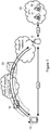
- FIG. 1 is an explanatory diagram for describing an example of a network configuration of LWIP assumed in 3GPP.
- an eNB 10 a LWIP-SeGW 20, a WLAN-AP 30, a UE 40, a mobility management entity (MME) 51 and a serving gateway (S-GW) 52 are illustrated.
- the eNB 10 and the UE 40 can transmit and receive data over a Uu interface, and can transmit and receive data via the LWIP-SeGW 20 and the WLAN-AP 30.
- the LWIP-SeGW 20 provides a Security Architecture for Internet Protocol (IPsec) tunnel for transmission and reception of data via a WLAN.
- IPsec Internet Protocol
- S1 S1-U for U-plane and S1-C for C-plane which is an interface between an E-UTRAN and an EPC 50 terminates at the eNB.
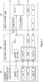
- FIG. 2 is an explanatory diagram for describing an example of a protocol stack of LWIP assumed in 3GPP Release-13.
- Data is transmitted and received between the LWIP-SeGW 20 and UE 40 using an encapsulation security payload (ESP).
- ESP encapsulation security payload
- data is transmitted and received between the eNB 10 and the LWIP-SeGW 20 using a new protocol.
- the new protocol is GRE or GTP-U, and User Datagram Protocol (UDP).
- uplink data is transmitted and received between the eNB 10 and the UE 40 using LWIPEP. That is, the UE 40 adds a LWIPEP header to uplink data transmitted via a WLAN.
- the eNB 10 which receives the uplink data, identifies a bearer corresponding to the uplink data from the LWIPEP header.
- LWIPEP may be implemented with GRE or GTP-U.
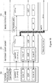
- Figure 3 is an explanatory diagram for describing an example of a protocol stack of LWIP assumed in 3GPP Release-14. Particularly in Release-14, uplink data is transmitted and received between the LWIP-SeGW 20 and UE 40 using LWIPEP. In addition, data is transmitted and received between the eNB 10 and the LWIP-SeGW 20 using a new protocol (for example, GRE or GTP-U, and UDP).
- a new protocol for example, GRE or GTP-U, and UDP.
- the eNB replaces the header for each data forwarding. Specifically, for example in downlink, the eNB replaces the header (a header of GTP-U) of a packet received from a core network with another header (a header of GRE or GTP-U). In addition, for example in uplink, an eNB replaces the header (a header of GRE or GTP-U) of a packet received from a LWIP-GW with another header (a header of GTP-U).
- a processing load of the eNB for data forwarding may be increased. Furthermore, since an eNB and a LWIP-SeGW exchange TEIDs of GTP-U or keys of GRE, a processing load of the eNB for such an exchange may be increased. In this way, there is concern that a processing load of the eNB is increased.
- the core network node exchanges TEIDs with a gateway or a WLAN-AP. Therefore, the load of the core network node may be increased.
- a UE communicates with both of a base station (an eNB or a NB) and a WLAN-AP, TEIDs for both of the base station and the WLAN-AP are exchanged, and the load of the core network may be increased. In this way, the core network may be greatly affected.
- An example object of example embodiments of the present disclosure is to make it possible to reduce effects on a core network and reduce a processing load of a base station in case of transmission and reception of data via a WLAN.
- a base station notifies a gateway (LWIP-SeGW) used for communication via a WLAN of a TEID of which one of the base station and a core network node (MME) notifies the other of the base station and the core network node.
- LWIP-SeGW gateway
- MME core network node
- the gateway transmits or receives a packet including a header containing the TEID based on the TEID.
- EPC core network
- eNB base station
- FIG. 4 is an explanatory diagram illustrating an example of a schematic configuration of the system 1 according to the example embodiments of the present disclosure.
- the system 1 includes a base station 100, a gateway 200, a WLAN-AP 300, a terminal apparatus 400 and a core network 500.
- the system 1 is a system that complies with 3GPP standards. More specifically, the system 1 may be a system that complies with LTE, LTE-Advanced and/or System Architecture Evolution (SAE). Alternatively, the system 1 may be a system that complies with a standard of Fifth Generation (5G). Of course, the system 1 is not limited to these examples.
- SAE System Architecture Evolution
- 5G Fifth Generation
- the base station 100 is a node which performs wireless communication with a terminal apparatus.
- the base station 100 is a node of a radio access network (RAN).
- the base station 100 may be an eNB, or may be a generation Node B (gNB) in 5G.
- the base station 100 may include a plurality of units (or a plurality of nodes).
- the plurality of units (or plurality of nodes) may include a first unit (or a first node) performing processing of a higher protocol layer, and a second unit (or a second node) performing processing of a lower protocol layer.
- the first unit may be referred to as a center/central unit (CU), and the second unit may be referred to as a distributed unit (DU) or an access unit (AU).
- the first unit may be referred to as a digital unit (DU)
- the second unit may be referred to as a radio unit (RU) or a remote unit (RU).
- the digital unit (DU) may be a base band unit (BBU)
- the RU may be a remote radio head (RRH) or a remote radio unit (RRU).
- RRH remote radio head
- RRU remote radio unit
- Terms used to refer to the first unit (or first node) and the second unit (or second node) are, of course, not limited to these examples.
- the base station 100 may be a single unit (or single node). In this case, the base station 100 may be one of the plurality of units (e.g. one of the first unit and the second unit) and may be connected to another one of the plurality of unit (e.g. the other one
- the base station 100 can transmit/receive data to/from the terminal apparatus 400 wirelessly (e.g. over a Uu interface), and can transmit/receive data to/from the terminal apparatus 400 via the gateway 200 and the WLAN-AP300.
- the base station 100 can perform operations of LWIP.
- the gateway 200 is a gateway used for communication via a WLAN and located between the base station 100 and the WLAN-AP300 & the terminal apparatus 400.
- the gateway 200 is a security gateway for ensuring security of communication via a WLAN.
- the gateway 200 provides a security tunnel (e.g. an IPsec tunnel) for communication via a WLAN.
- a security tunnel e.g. an IPsec tunnel
- the gateway 200 is a LWIP-SeGW.
- the WLAN-AP 300 is an access point of a WLAN and performs wireless communication with a terminal apparatus (e.g. the terminal apparatus 400) in conformity with one or more of IEEE 802.11 series (IEEE 802.11b/11a/11g/11n/11ac etc.).
- a terminal apparatus e.g. the terminal apparatus 400
- IEEE 802.11 series IEEE 802.11b/11a/11g/11n/11ac etc.
- the terminal apparatus 400 performs wireless communication with a base station.
- the terminal apparatus 400 performs wireless communication with the base station 100 when the terminal apparatus 400 is located in a coverage area of the base station 100.
- the terminal apparatus 400 is a UE.
- the terminal apparatus 400 can transmit/receive data to/from the base station 100 wirelessly (e.g. over a Uu interface), and can transmit/receive data to/from the base station 100 via the WLAN-AP 300 and the gateway 200.
- the terminal apparatus 400 can perform operations of LWIP.
- the core network 500 includes a first core network node 510 and a second core network node 520.
- the first core network node 510 is a node responsible for processing of C-plane. For example, the first core network node 510 transmits a control message to the base station 100, and receives a control message from the base station 100.
- the second core network node 520 is a node responsible for processing of U-plane. For example, the second core network node 520 transmits a data packet (a packet including data) to the base station 100, and receives a data packet from the base station 100.
- a data packet (a packet including data)
- the core network node 500 is an EPC
- the first core network node 510 is an MME
- the second core network node 520 is a S-GW.
- FIG. 5 is a block diagram illustrating an example of a schematic configuration of the base station 100 according to the first example embodiment.
- the base station 100 includes a wireless communication unit 110, a network communication unit 120, a storage unit 130 and a processing unit 140.
- the wireless communication unit 110 is configured to wirelessly transmit and receive signals.
- the wireless communication unit 110 is configured to receive signals from a terminal apparatus and transmit signals to a terminal apparatus.
- the network communication unit 120 is configured to receive signals from a network and transmit signals to a network.
- the storage unit 130 is configured to store programs and parameters for operation of the base station 100 as well as various data temporarily or permanently.
- the processing unit 140 is configured to provide various functions of the base station 100.
- the processing unit 140 includes an information obtaining unit 141, a first communication processing unit 143, a second communication processing unit 145, a third communication processing unit 147, and a control unit 149.
- the processing unit 140 may further include another constituent element than these constituent elements. That is, the processing unit 140 may perform operations other than the operations of these constituent elements. Specific operations of the information obtaining unit 141, the first communication processing unit 143, the second communication processing unit 145, the third communication processing unit 147, and the control unit 149 will be described in detail later.
- the processing unit 140 (the first communication processing unit 143) communicates with the gateway 200 through the network communication unit 120.
- the processing unit 140 (the second communication processing unit 145) communicates with a core network node (e.g. the first core network node 510 or the second core network node 520) through the network communication unit 120.
- the processing unit 140 (the third communication processing unit 147) communicates with a terminal apparatus (e.g. the terminal apparatus 400) through the wireless communication unit 110.
- the wireless communication unit 110 may be implemented with an antenna, a radio frequency (RF) circuit and the like.
- the network communication unit 120 may be implemented with a network adapter, a network interface card or the like.
- the storage unit 130 may be implemented with a memory (for example, non-volatile memory and/or volatile memory), hard disc and/or the like.
- the processing unit 140 may be implemented with a base band (BB) processor, another processor and/or the like.
- the information obtaining unit 141, the first communication processing unit 143, the second communication processing unit 145, the third communication processing unit 147 and the control unit 149 may be implemented with the same processor or with respective different processors.
- the above memory (storage unit 130) may be included in such a processor (a chip).
- the base station 100 may include a memory that stores a program and one or more processors that are capable of executing the program, and the one or more processors may execute the operations of the processing unit 140 (the information obtaining unit 141, the first communication processing unit 143, the second communication processing unit 145, the third communication processing unit 147 and the control unit 149).
- the program may be a program for causing a processor to execute the operations of the processing unit 140 (the operations of the information obtaining unit 141, the first communication processing unit 143, the second communication processing unit 145, the third communication processing unit 147 and the control unit 149).
- FIG. 6 is a block diagram illustrating an example of a schematic configuration of the gateway 200 according to the first example embodiment.
- the gateway 200 includes a network communication unit 210, a storage unit 220 and a processing unit 230.
- the network communication unit 210 is configured to receive signals from a network and transmit signals to a network.
- the storage unit 220 is configured to store programs and parameters for operation of the gateway 200 as well as various data temporarily or permanently.
- the processing unit 230 is configured to provide various functions of the gateway 200.
- the processing unit 230 includes a first communication processing unit 231 and a second communication processing unit 233.
- the processing unit 230 may further include another constituent element than these constituent elements. That is, the processing unit 230 may perform operations other than the operations of these constituent elements. Specific operations of the first communication processing unit 231 and the second communication processing unit 233 will be described in detail later.
- the processing unit 230 communicates with another node through the network communication unit 210.
- the processing unit 230 (the first communication processing unit 231) communicates with the terminal apparatus 400 via a WLAN (the WLAN-AP 300) through the network communication unit 210.
- the processing unit 230 (the second communication processing unit 233) communicates with the base station 100 (or a core network node) through the network communication unit 210.
- the network communication unit 210 may be implemented with a network adapter, a network interface card or the like.
- the storage unit 220 may be implemented with a memory (for example, non-volatile memory and/or volatile memory), hard disc and/or the like.
- the processing unit 230 may be implemented with a processor and/or the like.
- the first communication processing unit 231 and the second communication processing unit 233 may be implemented with the same processor or with respective different processors.
- the above memory (storage unit 220) may be included in such a processor (a chip).
- the gateway 200 may include a memory that stores a program and one or more processors that are capable of executing the program, and the one or more processors may execute the operations of the processing unit 230 (the operations of the first communication processing unit 231 and the second communication processing unit 233).
- the program may be a program for causing a processor to execute the operations of the processing unit 230 (the operations of the first communication processing unit 231 and the second communication processing unit 233).
- the base station 100 (the information obtaining unit 141) obtains a tunnel endpoint identifier (TEID) of which one of the base station 100 and the first core network node 510 notifies the other of the base station 100 and the first core network node 510. Then, the base station 100 (the first communication processing unit 143) notifies the gateway 200 of the TEID.
- TEID tunnel endpoint identifier
- the gateway 200 (the second communication processing unit 233) transmits or receives a packet including a header containing the TEID based on the TEID.
- the TEID is a GTP TEID.
- the TEID (of which the base station 100 notifies the gateway 200) is a TEID of the base station 100 side, of which the base station 100 notifies the first core network node 510. That is, the base station 100 also notifies the gateway 200 of a TEID of the base station 100 side in addition to notifying the first core network 510 (e.g. MME) of the TEID of the base station 100 side.
- the first core network 510 e.g. MME
- the TEID of the base station 100 side is assigned by the base station 100, and is included in a packet transmitted from the core network 500 (the second core network node 520) to the base station 100.
- the TEID of the base station 100 side can be also be referred to as a downlink TEID (e.g. DL GTP TEID).
- the base station 100 is an eNB
- the TEID of the base station 100 side is an eNB TEID.
- the gateway 200 enables the gateway 200 to receive a packet including the TEID and terminate a tunnel (e.g. a GTP-U tunnel) corresponding to the TEID. Therefore, as described later, replacement of a header by the base station 100 may be omitted, and a processing load of base station 100 may be reduced.
- a tunnel e.g. a GTP-U tunnel
- the gateway 200 since the base station 100 performs an assignment of a TEID and an exchange of the TEID with the first core network node 510, the gateway 200 does not have to perform these operations. Therefore, the first core network 510 does not need to perform any new operations. In this way, effects to the core network 500 may be reduced.
- the base station 100 receives, from the core network 500 (the second core network node 520), a packet including data addressed to the terminal apparatus 400 and a header containing the TEID of the base station 100 side.
- the header is a GTP-U header
- the packet is a GTP-U packet (or a UDP packet).
- the base station 100 (the first communication processing unit 143) transmits, to the gateway 200, the packet including the header and the data. That is, the base station 100 forwards the packet to the gateway 200 without performing replacement of a header (removal of the header and addition of a new header).
- the gateway 200 (the second communication processing unit 233) receives the packet from the base station 100 based on the TEID of the base station 100 side. Then, the gateway 200 (the first communication processing unit 231) transmits the data included in the packet to the terminal apparatus 400 via a WLAN (the WLAN-AP 300).
- a WLAN the WLAN-AP 300
- a termination point of a tunnel (e.g. a GTP-U tunnel) corresponding to the TEID is gateway 200. That is, the termination point of the tunnel is extended from the base station 100 to the gateway 200.
- the base station 100 may transmit the data to the terminal apparatus 400.
- the termination point of a tunnel (e.g. a GTP-U tunnel) corresponding to the TEID is the base station 100. That is, the termination point of the tunnel remains the base station 100.
- the base station 100 determines whether to transmit the data to the terminal apparatus 400 directly or transmit the data to the terminal apparatus 400 via a WLAN. For example, if it is determined to transmit the data to the terminal apparatus 400 directly, the base station 100 (the third communication processing unit 147) transmits the data to the terminal apparatus 400. On the other hand, for example, if it is determined to transmit the data to the terminal apparatus 400 via a WLAN (the WLAN-AP 300), the base station 100 (the first communication processing unit 143) transmits, to the gateway, the packet including the header and the data.
- a WLAN the WLAN-AP 300
- this makes it possible to perform, using the same TEID, direct transmission from the base station 100 to the terminal apparatus 400 and transmission to the terminal apparatus 400 via a WLAN. Therefore, processing for an assignment and an exchange of a TEID etc. may be reduced.
- the base station 100 (the control unit 149) performs the above described determination based on required quality per user or service, a status of utilization of radio resources, a status of a load of the gateway 200 or a WLAN (the WLAN-AP 300) and/or the like. For example, this makes it possible to provide a stable service to a user (the terminal apparatus 400).
- Figure 7 is an explanatory diagram for describing an example of a protocol stack according to a first example embodiment.
- the base station 100 eNB
- the gateway 200 does not have a GTP-U only for the gateway 200 in particular (as compared with an example of Figure 3 ).
- the base station 100 transmits, to the gateway 200, a GTP-U packet (or a UDP packet) received form the core network 500 (the second core network node 520) without replacement of a header (i.e. transparently). Then, the gateway 200 receives the GTP-U packet (or the UDP packet) based on a TEID of which the base station 100 notified the gateway 200 in advance. In this way, a GTP-U terminates at the gateway 200.
- the base station 100 removes the GTP-U header from a received GTP-U packet, and transmit the remaining data to the terminal apparatus 400. In this way, a GTP-U terminates at the base station 100.
- the TEID (of which the base station 100 notifies the gateway 200) may be a TEID for multicast (a common TEID) instead of a TEID of the base station 100 side.
- the first core network node 510 may notify the base station 100 of the TEID for the multicast.
- the TEID for the multicast may be referred to as a Common TEID (C-TEID).
- the multicast may be Multimedia Broadcast Multicast Service (MBMS).
- MBMS Multimedia Broadcast Multicast Service
- the TEID for the multicast (e.g. the C-TEID) may be used for transmission and reception of data as well as the TEID of the base station 100 side. That is, in the above description for transmission and reception of data, the TEID of the base station 100 side may be replaced with the TEID for the multicast.
- the TEID (of which the base station 100 notifies the gateway 200) is a TEID of the core network 500 side of which the first core network node 510 notifies the base station 100. That is the base station 100 (the first communication processing unit 143) notifies the gateway 200 a TEID of the core network 500 side of which the first core network node 510 (e.g. MME) notifies the base station 100.
- the TEID of the core network 500 side is assigned in the core network 500, and is included in a packet transmitted from the base station 100 to the core network 500 (the second core network node 520).
- the TEID of the core network 500 side can be also said as an uplink TEID (e.g. UL GTP TEID).
- the core network 500 is an EPC
- the TEID of the core network 500 side is an EPC TEID.
- the base station 100 since the base station 100 notifies the gateway 200 of a TEID of the core network 500 side, the first core network node 510 does not need to perform any new operation (e.g. notification of a TEID to the gateway 200). Furthermore, since contents of a packet (e.g. a GTP-U packet) transmitted to the core network 500 does not change, the second core network node 520 may receive the packet regardless of existence of the gateway 200. In this way, effects to the core network 500 may be reduced.
- a packet e.g. a GTP-U packet
- the gateway 200 (the first communication processing unit 231) receives data from the terminal apparatus 400 via a WLAN (the WLAN-AP 300). Then, the gateway 200 (the second communication processing unit 233) transmits, to the base station 100, a packet including the data and a header containing the TEID of the core network 500 side.
- the base station 100 (the first communication processing unit 143) receives the packet from the gateway 200. Then, the base station 100 (the second communication processing unit 145) transmits, to the core network 500 (the second core network node 520), the packet including the header and the data. That is, the base station 100 forwards the packet to the core network 500 (the second core network node 520) without performing replacement of a header (removal of the header and addition of a new header).
- the base station 100 does not have a GTP-U only for the gateway 200 in particular (as compared with an example of Figure 3 ) as described above.
- the gateway 200 generates a GTP-U packet including data received from the terminal apparatus 400 and a GTP-U header containing a TEID of which the base station 100 notifies the gateway 200 in advance, and transmits the GTP-U packet.
- the base station 100 transmits the GTP-U packet (or a UDP packet) to the core network 500 (the second core network node 520) without replacement of a header (i.e. transparently).
- the base station 100 (the first communication processing unit 143) notifies the gateway 200 of the TEID.
- the base station 100 (the first communication processing unit 143) transmits a message including the TEID to the gateway 200.
- the base station 100 may transmit the message using a frame protocol (GTP-U, GRE, Stream Control Transmission Protocol (SCTP), Transmission Control Protocol (TCP), GTP version 1 Control (GTPv1-C), GTP version 2 Control (GTPv2-C), Radio Access Network Application Part (RANAP), S1 Application Protocol (S1-AP) or the like), for example.
- GTP-U GRE
- SCTP Stream Control Transmission Protocol
- TCP Transmission Control Protocol
- GTPv1-C GTP version 1 Control
- GTPv2-C GTP version 2 Control
- RANAP Radio Access Network Application Part
- S1-AP S1 Application Protocol
- the message is a message for setting of a TEID.
- the base station 100 (the first communication processing unit 143) may further transmit, to the gateway 200, a message for release of TEID.
- the base station 100 (the information obtaining unit 141) may obtain not one of but both of the TEID of the base station 100 side and the TEID of the core network 500 side. Then, the base station 100 (the first communication processing unit 143) may notify the gateway 200 of both of the TEID of the base station 100 side and the TEID of the core network 500 side.
- the base station 100 obtains the TEID and quality of service information corresponding to the TEID. Then the base station 100 (the first communication processing unit 143) notifies the gateway 200 of the TEID and the quality of service information.
- the quality of service information is a quality of service class identifier (QCI) or bearer information of bearer identified from the TEID.
- QCI quality of service class identifier
- bearer information of bearer identified from the TEID is not limited to this example, and may be other information (e.g. a DiffServ Code Point (DSCP), an IP flow or the like).
- DSCP DiffServ Code Point
- the gateway 200 (the first communication processing unit 231) may perform priority control for transmission and reception of data based on the quality of service information.
- a stable service may be provided to a user (the terminal apparatus 400).
- Figure 8 is a sequence diagram for describing an example of a schematic flow of processing according to a first example embodiment.
- the base station 100 itself assigns the eNB TEID and is notified of the EPC TEID by the first core network node 510.
- the base station 100 transmits a message for setting of a TEID to the gateway 200, and the gateway 200 receives the message (S603).
- the gateway 200 transmits a message of acknowledge (ACK) to the base station 100, and the base station 100 receives the message (S607).
- ACK acknowledge
- the base station 100 transmits a message for release of a TEID to the gateway 200, and the gateway 200 receives the message (S611).
- the gateway 200 transmits a message of ACK to the base station 100, and the base station 100 receives the message (S615).
- the gateway 200 (the second communication processing unit 233) transmits or receives a packet including a header containing the TEID based on the TEID (of which the base station 100 notifies the gateway 200).
- the gateway 200 (the second communication processing unit 233) transmits the packet to the core network 500 or receives the packet from the core network 500 not via the base station 100.
- a processing load of the base station 100 may be further reduced.
- a network topology may be more flexible.
- the second core network node 520 transmits, to the gateway 200 not via base station 100, a packet including the TEID of the base station 100 side and data addressed to the terminal apparatus 400. Then, the gateway 200 (the second communication processing unit 233) receives the packet based on the TEID of the base station 100 side.
- the TEID of the base station 100 side is an identifier to be included in a packet transmitted from the core network 500 to the gateway 200 not via the base station 100.
- Figure 9 is an explanatory diagram for describing a first example of a protocol stack according to a modified example of a first example embodiment.
- the gateway 200 has an S1-U interface, and receives, from the second core network node 520 not via the base station 100, a packet including a TEID of the base station 100 side in a GTP-U header.
- the base station 100 obtains the TEID of the base station 100 side and a transport layer address (e.g. an IP address) of the gateway 200. Then, the base station 100 (the second communication processing unit 145) notifies the first core network node 510 of the TEID of the base station 100 side and the transport layer address. For example, the base station 100 notifies the first core network node 510 of the transport layer address of the gateway 200 instead of a transport layer address of the base station 100. This, for example, enables the second core network node 520 to transmit the packet directly to the gateway 200 not via the base station 100.
- a transport layer address e.g. an IP address
- the gateway 200 (the second communication processing unit 233) transmits, to the second core network node 520 not via the base station 100, a packet including the TEID of the core network 500 side and data from the terminal apparatus 400.
- the TEID of the core network 500 side is an identifier to be included in a packet transmitted from the gateway 200 to the core network 500 not via the base station 100.
- the gateway 200 has an S1-U interface, and transmits, to the second core network node 520 not via the base station 100, a packet including a TEID of the core network 500 side in a GTP-U header.
- the base station 100 obtains a transport layer address (e.g. an IP address) of the core network 500 side. Then, the base station 100 (the first communication processing unit 143) notifies the gateway 200 of the transport layer address.
- the transport layer address is a transport layer address of the second core network node 520 (e.g. a S-GW). This, for example, enables the gateway 200 to transmit the packet directly to the core network 500 (the second core network node 520) not via the base station 100.
- the gateway 200 (the second communication processing unit 233) may transmit the packet to the core network 500 or receive the packet from the core network 500 via a security gateway of the backhaul side. Thereby, security of communication between the gateway 200 and the core network 500 may be ensured.
- Figure 10 is an explanatory diagram for describing a second example of a protocol stack according to a modified example of a first example embodiment.
- the gateway 200 transmits a packet to the second core network node 520 or receive a packet from the second core network node 520 via a security gateway (SeGW) of the backhaul side.
- SeGW security gateway
- the base station 100 may obtain connection information for a connection with the security gateway of the backhaul side. Then, the base station 100 (the first communication processing unit 143) may notify the gateway 200 of the connection information.
- the gateway 200 (the second communication processing unit 233) may establish a connection with the security gateway of the backhaul side based on the connection information.
- the connection with the security gateway of the backhaul side may be a security tunnel (e.g. an IPsec tunnel).
- the connection information may include an electronic certificate for a connection with the security gateway of the backhaul side. This, for example, enables transmission and reception of a packet via a security gateway of the backhaul side.
- the first example embodiment has been described above. According to the first example embodiment, for example, it is possible to reduce effects to the core network 500 and reduce a processing load of the base station 100 in case of transmission and reception of data via a WLAN.
- Figure 11 is a block diagram illustrating an example of a schematic configuration of the base station 100 according to the second example embodiment.
- the base station 100 includes an information obtaining unit 151 and the first communication processing unit 153.
- the information obtaining unit 151 and the first communication processing unit 153 may be implemented with a base band (BB) processor, another processor and/or the like.
- the information obtaining unit 151 and the first communication processing unit 153 may be implemented with the same processor or with respective different processors.
- the base station 100 may include a memory that stores a program and one or more processors that are capable of executing the program, and the one or more processors may execute the operations of the information obtaining unit 151 and the first communication processing unit 153.
- the program may be a program for causing a processor to execute the operations of the information obtaining unit 151 and the first communication processing unit 153.
- FIG. 12 is a block diagram illustrating an example of a schematic configuration of the gateway 200 according to the second example embodiment.
- the gateway 200 includes a first communication processing unit 241 and a second communication processing unit 243.
- the first communication processing unit 241 and the second communication processing unit 243 may be implemented with a processor and/or the like.
- the first communication processing unit 241 and the second communication processing unit 243 may be implemented with the same processor or with respective different processors.
- the gateway 200 may include a memory that stores a program and one or more processors that are capable of executing the program, and the one or more processors may execute the operations of the first communication processing unit 241 and the second communication processing unit 243.
- the program may be a program for causing a processor to execute the operations of the first communication processing unit 241 and the second communication processing unit 243.
- the base station 100 obtains a tunnel endpoint identifier (TEID) of which one of the base station 100 and the first core network node 510 notifies the other of the base station 100 and the first core network node 510. Then, the base station 100 (the first communication processing unit 153) notifies the gateway 200 of the TEID.
- TEID tunnel endpoint identifier
- the gateway 200 (the second communication processing unit 243) transmits or receive a packet including a header containing the TEID based on the TEID.
- the second example embodiment has been described above. According to the second example embodiment, for example, it is possible to reduce effects to the core network 500 and reduce a processing load of the base station 100 in case of transmission and reception of data via a WLAN.
- any processing described herein need not be performed chronologically in the order illustrated in the corresponding sequence diagram.
- the steps of the processing may be performed in an order different from the order illustrated as the corresponding sequence diagram or may be performed in parallel.
- one or some of the steps of the processing may be deleted, or one or more steps may be added to the processing.
- an apparatus e.g. one or more apparatuses (or units) out of a plurality of apparatuses (or units) constituting the base station, or a module for one of the plurality of apparatuses (or units)
- constituent elements of the base station described herein e.g. the information obtaining unit, the first communication processing unit, the second communication processing unit, the third communication processing unit and/or the control unit
- An apparatus e.g. a module for the gateway including constituent elements of the gateway described herein (e.g. the first communication processing unit and/or the second communication processing unit) may be provided.
- methods including processing of such constituent elements may be provided, and programs for causing processors to execute processing of such constituent elements may be provided.
- non-transitory computer readable recording media having recorded thereon the program may be provided.
- such apparatuses, methods, programs and non-transitory computer readable recording media are also included in the present disclosure.
- a base station comprising:
- tunnel endpoint identifier is a tunnel endpoint identifier of the base station side of which the base station notifies the core network node.
- the base station according to Supplementary Note 2, wherein the base station is an evolved Node B (eNB), and the tunnel endpoint identifier of the base station side is an eNB tunnel endpoint identifier (TEID).
- eNB evolved Node B
- TEID eNB tunnel endpoint identifier
- the base station according to any one of Supplementary Notes 1 to 3, further comprising:
- the tunnel endpoint identifier is an identifier to be included in a packet transmitted from a core network to the gateway not via the base station.
- the base station according to any one of Supplementary Notes 1, 2, 3 and 7, wherein the information obtaining unit is configured to obtain the tunnel endpoint identifier and a transport layer address of the gateway, the base station further comprises a second communication processing unit configured to notify the core network node of the tunnel endpoint identifier and the transport layer address.
- tunnel endpoint identifier is a tunnel endpoint identifier of the core network side of which the core network node notifies the base station.
- the base station according to Supplementary Note 9, wherein the core network is an Evolved Packet Core (EPC), and the tunnel endpoint identifier of the core network side is an EPC TEID.
- EPC Evolved Packet Core
- the base station according to any one of Supplementary Notes 1, 9 and 10, wherein the first communication processing unit is configured to receive, from the gateway, a packet including data from a terminal apparatus and a header containing the tunnel endpoint identifier, and the base station further comprises a second communication processing unit configured to transmit, to a core network, the packet including the header and the data.
- the base station according to any one of Supplementary Notes 1, 9 and 10, wherein the tunnel endpoint identifier is an identifier to be included in a packet transmitted from the gateway to a core network not via the base station.
- the base station according to any one of Supplementary Notes 1, 9, 10 and 12, wherein the information obtaining unit is configured to obtain a transport layer address of the core network side, and the first communication processing unit is configured to notify the gateway of the transport layer address.
- the transport layer address of the core network side is a transport layer address of a serving gateway included in the core network.
- the base station according to any one of Supplementary Notes 1 to 14, wherein the information obtaining unit is configured to obtain the tunnel endpoint identifier and quality of service information corresponding to the tunnel endpoint identifier, and the first communication processing unit is configured to notify the gateway of the tunnel endpoint identifier and the quality of service information.
- the quality of service information is a quality of service class identifier of a bearer identified from the tunnel endpoint identifier.
- the base station according to any one of Supplementary Notes 1 to 16, wherein the information obtaining unit is configured to obtain connection information for a connection with a security gateway of the backhaul side, the first communication processing unit is configured to notify the gateway of the connection information, and the security gateway of the backhaul side is a gateway which data goes through to be transmitted from one of the gateway and a core network to the other of the gateway and the core network.
- connection information includes an electronic certificate for a connection with the security gateway of the backhaul side.
- the tunnel endpoint identifier is a GPRS Tunneling Protocol (GTP) TEID.
- GTP GPRS Tunneling Protocol
- the base station according to any one of Supplementary Notes 1 to 19, wherein the base station is an eNB, and the core network node is a mobility management entity (MME).
- MME mobility management entity
- the gateway is a security gateway for ensuring security of communication via a wireless local area network.
- the gateway is LTE WLAN RAN Level Integration using IPSec Security Gateway (LWIP-SeGW).
- a gateway comprising:
- the tunnel endpoint identifier is a tunnel endpoint identifier of the base station side of which the base station notifies the core network node
- the second communication processing unit is configured to receive, based on the tunnel endpoint identifier, a packet including data addressed to the terminal apparatus and a header containing the tunnel endpoint identifier.
- the tunnel endpoint identifier is a tunnel endpoint identifier of the core network side of which the core network node notifies the base station
- the second communication processing unit is configured to transmit a packet including data from the terminal apparatus and a header containing the tunnel endpoint identifier.
- the gateway according to any one of Supplementary Notes 23 to 25, wherein the second communication processing unit is configured to transmit the packet to the base station or receive the packet from the base station.
- the gateway according to any one of Supplementary Notes 23 to 25, wherein the second communication processing unit is configured to transmit the packet to a core network or receive the packet from the core network not via the base station.
- a method comprising:
- An apparatus comprising:
- An apparatus comprising:
- An apparatus comprising:
- the apparatus according to any one of Supplementary Notes 33 to 35, wherein the apparatus is the base station, one or more apparatuses out of a plurality of apparatuses constituting the base station, or a module for one of the plurality of apparatuses.
- a method comprising:
- An apparatus comprising:
- An apparatus comprising:
- An apparatus comprising:
- the apparatus according to any one of Supplementary Notes 40 to 42, wherein the apparatus is the gateway, or a module for the gateway.
Landscapes
- Engineering & Computer Science (AREA)
- Computer Networks & Wireless Communication (AREA)
- Signal Processing (AREA)
- Mobile Radio Communication Systems (AREA)
Abstract
Description
- The present disclosure relates to a base station, a gateway, an apparatus, a method, a program and a recording medium.
- Currently, in Third Generation Partnership Project (3GPP), development of LTE/WLAN Radio Level Integration with IPsec Tunnel (LWIP) as a data transmission scheme with the use of both of an evolved Node B (eNB) and a wireless local area network access point (WLAN-AP) is ongoing.
- In 3GPP Release-13 and Release-14, S1-U which is an interface of U-plane between an Evolved Universal Terrestrial Radio Access Network (E-UTRAN) and an Evolved Packet Core (EPC) terminates at an eNB, and an eNB transmits/receives data to/from an LWIP Security Gateway (LWIP-SeGW). GPRS Tunneling Protocol for User Plane (GTP-U) is used for S1-U. In addition, a frame protocol such as Generic Routing Encapsulation (GRE), GPRS Tunneling Protocol for User Plane (GTP-U) or the like is used for transmission and reception of data between an eNB and an LWIP-SeGW.
- For example, technologies related to LWIP are disclosed in
NPL 1 and NPL 2. Specifically, a protocol stack for LWIP is disclosed in NPL 1 and NPL 2. - For example, PTL1 and PTL2 disclose that a gateway connected to a WLAN-AP or a WLAN-AP itself communicates with a core network node using a GTP-U protocol.
-
- [PTL 1]
JP 2016-507993 T - [PTL 2]
JP 2005-529560 T -
- [NPL 1] 3GPP TS 36.300 V13.4.0 (2016-06) "3rd Generation Partnership Project; Technical Specification Group Radio Access Network; Evolved Universal Terrestrial Radio Access (E-UTRA) and Evolved Universal Terrestrial Radio Access Network (E-UTRAN); Overall description; Stage 2 (Release 13)"
- [NPL 2] 3GPP TS 33.401 V13.3.0 (2016-06) "3rd Generation Partnership Project; Technical Specification Group Services and System Aspects; 3GPP System Architecture Evolution (SAE); Security architecture (Release 13)"
- For example, when a termination point of S1-U is an eNB and GRE or GTP-U is used for transmission and reception of data between an eNB and LWIP-SeGW as disclosed in NPL 2, the eNB replaces the header for each data forwarding. Specifically, for example in downlink, the eNB replaces the header (a header of GTP-U) of a packet received from a core network with another header (a header of GRE or GTP-U). In addition, for example in uplink, the eNB replaces the header (a header of GRE or GTP-U) of a packet received from a LWIP-GW with another header (a header of GTP-U). Therefore, a processing load of the eNB for data forwarding may be increased. Furthermore, since an eNB and a LWIP-SeGW exchange tunnel endpoint identifiers (TEIDs) of GTP-U or keys of GRE, a processing load of the eNB for such an exchange may be increased. In this way, there is concern that a processing load of the eNB is increased.
- In addition, for example, when a gateway connected to a WLAN-AP or a WLAN-AP itself communicates with a core network node using a GTP-U protocol as disclosed in
PTL 1 and PTL 2, the core network node exchanges TEIDs with the gateway or the WLAN-AP. Therefore, a load of the core network node may be increased. In particular, when a user equipment (UE) communicates with both of a base station (an eNB or a NB) and a WLAN-AP, TEIDs for both of the base station and the WLAN-AP are exchanged, and the load of the core network may be increased. In this way, the core network may be greatly affected. - An example object of the present disclosure is to make it possible to reduce effects on a core network and reduce a processing load of a base station in case of transmission and reception of data via a WLAN.
- A base station according to an example aspect of the present disclosure includes an information obtaining unit configured to obtain a tunnel endpoint identifier of which one of the base station and a core network node notifies the other of the base station and the core network node, and a first communication processing unit configured to notify, of the tunnel endpoint identifier, a gateway used for communication via a wireless local area network.
- A gateway according to an example aspect of the present disclosure includes a first communication processing unit configured to communicate with a terminal apparatus via a wireless local area network, and a second communication processing unit configured to transmit or receive, based on a tunnel endpoint identifier of which one of a base station and a core network node notifies the other of the base station and the core network node and of which the base station notifies the gateway, a packet including a header containing the tunnel endpoint identifier.
- A first method according to an example aspect of the present disclosure includes obtaining a tunnel endpoint identifier of which one of a base station and a core network node notifies the other of the base station and the core network node, and notifying, of the tunnel endpoint identifier, a gateway used for communication via a wireless local area network.
- A first program according to an example aspect of the present disclosure is a program for causing a processor to execute obtaining a tunnel endpoint identifier of which one of a base station and a core network node notifies the other of the base station and the core network node, and notifying, of the tunnel endpoint identifier, a gateway used for communication via a wireless local area network.
- A first recording medium according to an example aspect of the present disclosure is a non-transitory computer readable recording medium having recorded thereon a program for causing a processor to execute obtaining a tunnel endpoint identifier of which one of a base station and a core network node notifies the other of the base station and the core network node, and notifying, of the tunnel endpoint identifier, a gateway used for communication via a wireless local area network.
- A first apparatus according to an example aspect of the present disclosure includes an information obtaining unit configured to obtain a tunnel endpoint identifier of which one of a base station and a core network node notifies the other of the base station and the core network node, and a first communication processing unit configured to notify, of the tunnel endpoint identifier, a gateway used for communication via a wireless local area network.
- A second apparatus according to an example aspect of the present disclosure includes a memory storing a program, and one or more processors capable of executing the program, wherein the program is a program for causing a processor to execute obtaining a tunnel endpoint identifier of which one of a base station and a core network node notifies the other of the base station and the core network node, and notifying, of the tunnel endpoint identifier, a gateway used for communication via a wireless local area network.
- A third apparatus according to an example aspect of the present disclosure includes a memory, and one or more processors, wherein the one or more processors are configured to obtain a tunnel endpoint identifier of which one of a base station and a core network node notifies the other of the base station and the core network node, and notify, of the tunnel endpoint identifier, a gateway used for communication via a wireless local area network.
- A second method according to an example aspect of the present disclosure includes communicating with a terminal apparatus via a wireless local area network, and transmitting or receiving, based on a tunnel endpoint identifier of which one of a base station and a core network node notifies the other of the base station and the core network node and of which the base station notifies a gateway, a packet including a header containing the tunnel endpoint identifier.
- A second program according to an example aspect of the present disclosure is a program for causing a processor to execute communicating with a terminal apparatus via a wireless local area network, and transmitting or receiving, based on a tunnel endpoint identifier of which one of a base station and a core network node notifies the other of the base station and the core network node and of which the base station notifies a gateway, a packet including a header containing the tunnel endpoint identifier.
- A second recording medium according to an example aspect of the present disclosure is a non-transitory computer readable recording medium having recorded thereon a program for causing a processor to execute, communicating with a terminal apparatus via a wireless local area network, and transmitting or receiving, based on a tunnel endpoint identifier of which one of a base station and a core network node notifies the other of the base station and the core network node and of which the base station notifies a gateway, a packet including a header containing the tunnel endpoint identifier.
- A fourth apparatus according to an example aspect of the present disclosure includes a first communication processing unit configured to communicate with a terminal apparatus via a wireless local area network, and a second communication processing unit configured to transmit or receive, based on a tunnel endpoint identifier of which one of a base station and a core network node notifies the other of the base station and the core network node and of which the base station notifies a gateway, a packet including a header containing the tunnel endpoint identifier.
- A fifth apparatus according to an example aspect of the present disclosure includes a memory storing a program, and one or more processors capable of executing the program, wherein the program is a program for causing a processor to execute communicating with a terminal apparatus via a wireless local area network, and transmitting or receiving, based on a tunnel endpoint identifier of which one of a base station and a core network node notifies the other of the base station and the core network node and of which the base station notifies a gateway, a packet including a header containing the tunnel endpoint identifier.
- A sixth apparatus according to an example aspect of the present disclosure includes a memory, and one or more processors, wherein the one or more processors are configured to communicate with a terminal apparatus via a wireless local area network, and transmit or receive, based on a tunnel endpoint identifier of which one of a base station and a core network node notifies the other of the base station and the core network node and of which the base station notifies a gateway, a packet including a header containing the tunnel endpoint identifier. Advantageous Effects of Disclosure
- According to an example aspect of the present disclosure, it is possible to reduce effects on a core network and reduce a processing load of a base station in case of transmission and reception of data via a WLAN. Note that the present disclosure may exert other advantageous effects instead of the above advantageous effects or together with the above advantageous effects.
-
-
Figure 1 is an explanatory diagram for describing an example of a network configuration of LWIP assumed in 3GPP. -
Figure 2 is an explanatory diagram for describing an example of a protocol stack of LWIP assumed in 3GPP Release-13. -
Figure 3 is an explanatory diagram for describing an example of a protocol stack of LWIP assumed in 3GPP Release-14. -
Figure 4 is an explanatory diagram illustrating an example of a schematic configuration of a system according to example embodiments of the present disclosure. -
Figure 5 is a block diagram illustrating an example of a schematic configuration of a base station according to a first example embodiment. -
Figure 6 is a block diagram illustrating an example of a schematic configuration of a gateway according to a first example embodiment. -
Figure 7 is an explanatory diagram for describing an example of a protocol stack according to a first example embodiment. -
Figure 8 is a sequence diagram for describing an example of a schematic flow of processing according to a first example embodiment. -
Figure 9 is an explanatory diagram for describing a first example of a protocol stack according to a modified example of a first example embodiment. -
Figure 10 is an explanatory diagram for describing a second example of a protocol stack according to a modified example of a first example embodiment. -
Figure 11 is a block diagram illustrating an example of a schematic configuration of a base station according to a second example embodiment. -
Figure 12 is a block diagram illustrating an example of a schematic configuration of a gateway according to a second example embodiment. - Example embodiments of the present disclosure will be described below in detail with reference to the accompanying drawings. Note that, in the present description and drawings, elements to which the same or similar descriptions are applicable are denoted by the same reference signs, whereby overlapping descriptions may be omitted.
- Description will be given in the following order.
- 1. Related Art
- 2. Overview of Example Embodiments of the Present disclosure
- 3. Configuration of System according to Example Embodiments of the Present disclosure
- 4. First Example Embodiment
- 4.1. Configuration of Base Station
- 4.2. Configuration of Gateway
- 4.3. Technical Features
- 4.4. Modified Example
- 5. Second Example Embodiment
- 5.1. Configuration of Base Station
- 5.2. Configuration of Gateway
- 5.3. Technical Features
- LWIP is described as a related art related to the present example embodiments with reference to
Figure 1 to Figure3 . - In the present day, in 3GPP, development of LWIP as a data transmission scheme with the use of both of an eNB and a WLAN-AP is ongoing.
-
Figure 1 is an explanatory diagram for describing an example of a network configuration of LWIP assumed in 3GPP. Referring toFigure 1 , aneNB 10, a LWIP-SeGW 20, a WLAN-AP 30, aUE 40, a mobility management entity (MME) 51 and a serving gateway (S-GW) 52 are illustrated. In LWIP, theeNB 10 and theUE 40 can transmit and receive data over a Uu interface, and can transmit and receive data via the LWIP-SeGW 20 and the WLAN-AP 30. The LWIP-SeGW 20 provides a Security Architecture for Internet Protocol (IPsec) tunnel for transmission and reception of data via a WLAN. In addition, S1 (S1-U for U-plane and S1-C for C-plane) which is an interface between an E-UTRAN and anEPC 50 terminates at the eNB. -
Figure 2 is an explanatory diagram for describing an example of a protocol stack of LWIP assumed in 3GPP Release-13. Data is transmitted and received between the LWIP-SeGW 20 andUE 40 using an encapsulation security payload (ESP). In addition, data is transmitted and received between theeNB 10 and the LWIP-SeGW 20 using a new protocol. For example, the new protocol is GRE or GTP-U, and User Datagram Protocol (UDP). Furthermore, for uplink, uplink data is transmitted and received between theeNB 10 and theUE 40 using LWIPEP. That is, theUE 40 adds a LWIPEP header to uplink data transmitted via a WLAN. TheeNB 10, which receives the uplink data, identifies a bearer corresponding to the uplink data from the LWIPEP header. Note that, for example, LWIPEP may be implemented with GRE or GTP-U. -
Figure 3 is an explanatory diagram for describing an example of a protocol stack of LWIP assumed in 3GPP Release-14. Particularly in Release-14, uplink data is transmitted and received between the LWIP-SeGW 20 andUE 40 using LWIPEP. In addition, data is transmitted and received between theeNB 10 and the LWIP-SeGW 20 using a new protocol (for example, GRE or GTP-U, and UDP). - For example, when a termination point of S1-U is an eNB and GRE or GTP-U is used for transmission and reception of data between an eNB and LWIP-SeGW as disclosed in 3GPP TS 33.401 V13.3.0, the eNB replaces the header for each data forwarding. Specifically, for example in downlink, the eNB replaces the header (a header of GTP-U) of a packet received from a core network with another header (a header of GRE or GTP-U). In addition, for example in uplink, an eNB replaces the header (a header of GRE or GTP-U) of a packet received from a LWIP-GW with another header (a header of GTP-U). Therefore, a processing load of the eNB for data forwarding may be increased. Furthermore, since an eNB and a LWIP-SeGW exchange TEIDs of GTP-U or keys of GRE, a processing load of the eNB for such an exchange may be increased. In this way, there is concern that a processing load of the eNB is increased.
- In addition, for example, when a gateway connected to a WLAN-AP or a WLAN-AP itself communicates with a core network node using a GTP-U protocol as disclosed in
JP 2016-507993 T JP 2005-529560 T - An example object of example embodiments of the present disclosure is to make it possible to reduce effects on a core network and reduce a processing load of a base station in case of transmission and reception of data via a WLAN.
- According to the example embodiments of the present disclosure, for example, a base station (eNB) notifies a gateway (LWIP-SeGW) used for communication via a WLAN of a TEID of which one of the base station and a core network node (MME) notifies the other of the base station and the core network node.
- On the other hand, the gateway (LWIP-SeGW) transmits or receives a packet including a header containing the TEID based on the TEID.
- This makes it possible, for example, to reduce effects on a core network (EPC) and reduce a processing load of a base station (eNB) in case of transmission and reception of data via a WLAN.
- Note that, the above described technical feature is one specific example of the example embodiments of the present disclosure, and of course the example embodiments are not limited to the above described technical feature.
- An example of a configuration of a
system 1 according to the example embodiments is described with reference toFigure 4. Figure 4 is an explanatory diagram illustrating an example of a schematic configuration of thesystem 1 according to the example embodiments of the present disclosure. Referring toFigure 4 , thesystem 1 includes abase station 100, agateway 200, a WLAN-AP 300, aterminal apparatus 400 and acore network 500. - For example, the
system 1 is a system that complies with 3GPP standards. More specifically, thesystem 1 may be a system that complies with LTE, LTE-Advanced and/or System Architecture Evolution (SAE). Alternatively, thesystem 1 may be a system that complies with a standard of Fifth Generation (5G). Of course, thesystem 1 is not limited to these examples. - The
base station 100 is a node which performs wireless communication with a terminal apparatus. In other word, thebase station 100 is a node of a radio access network (RAN). For example, thebase station 100 may be an eNB, or may be a generation Node B (gNB) in 5G. Thebase station 100 may include a plurality of units (or a plurality of nodes). The plurality of units (or plurality of nodes) may include a first unit (or a first node) performing processing of a higher protocol layer, and a second unit (or a second node) performing processing of a lower protocol layer. As an example, the first unit may be referred to as a center/central unit (CU), and the second unit may be referred to as a distributed unit (DU) or an access unit (AU). As another example, the first unit may be referred to as a digital unit (DU), and the second unit may be referred to as a radio unit (RU) or a remote unit (RU). The digital unit (DU) may be a base band unit (BBU), and the RU may be a remote radio head (RRH) or a remote radio unit (RRU). Terms used to refer to the first unit (or first node) and the second unit (or second node) are, of course, not limited to these examples. Alternatively, thebase station 100 may be a single unit (or single node). In this case, thebase station 100 may be one of the plurality of units (e.g. one of the first unit and the second unit) and may be connected to another one of the plurality of unit (e.g. the other one of the first unit and the second unit). - In particular, according to the example embodiments, the
base station 100 can transmit/receive data to/from theterminal apparatus 400 wirelessly (e.g. over a Uu interface), and can transmit/receive data to/from theterminal apparatus 400 via thegateway 200 and the WLAN-AP300. Specifically, for example, thebase station 100 can perform operations of LWIP. - The
gateway 200 is a gateway used for communication via a WLAN and located between thebase station 100 and the WLAN-AP300 & theterminal apparatus 400. - For example, the
gateway 200 is a security gateway for ensuring security of communication via a WLAN. For example, thegateway 200 provides a security tunnel (e.g. an IPsec tunnel) for communication via a WLAN. More specifically, for example, thegateway 200 is a LWIP-SeGW. - The WLAN-
AP 300 is an access point of a WLAN and performs wireless communication with a terminal apparatus (e.g. the terminal apparatus 400) in conformity with one or more of IEEE 802.11 series (IEEE 802.11b/11a/11g/11n/11ac etc.). - The
terminal apparatus 400 performs wireless communication with a base station. For example, theterminal apparatus 400 performs wireless communication with thebase station 100 when theterminal apparatus 400 is located in a coverage area of thebase station 100. For example, theterminal apparatus 400 is a UE. - Particularly, in the present example embodiments, the
terminal apparatus 400 can transmit/receive data to/from thebase station 100 wirelessly (e.g. over a Uu interface), and can transmit/receive data to/from thebase station 100 via the WLAN-AP 300 and thegateway 200. Specifically, for example, theterminal apparatus 400 can perform operations of LWIP. - The
core network 500 includes a firstcore network node 510 and a secondcore network node 520. - The first
core network node 510 is a node responsible for processing of C-plane. For example, the firstcore network node 510 transmits a control message to thebase station 100, and receives a control message from thebase station 100. - The second
core network node 520 is a node responsible for processing of U-plane. For example, the secondcore network node 520 transmits a data packet (a packet including data) to thebase station 100, and receives a data packet from thebase station 100. - For example, the
core network node 500 is an EPC, the firstcore network node 510 is an MME, and the secondcore network node 520 is a S-GW. - Subsequently, a first example embodiment of the present disclosure will be described with reference to
Figure 5 to Figure 10 . - Firstly, an example of a configuration of the
base station 100 according to the first example embodiment is described with reference toFigure 5. Figure 5 is a block diagram illustrating an example of a schematic configuration of thebase station 100 according to the first example embodiment. Referring toFigure 5 , thebase station 100 includes awireless communication unit 110, anetwork communication unit 120, astorage unit 130 and aprocessing unit 140. - The
wireless communication unit 110 is configured to wirelessly transmit and receive signals. For example, thewireless communication unit 110 is configured to receive signals from a terminal apparatus and transmit signals to a terminal apparatus. - The
network communication unit 120 is configured to receive signals from a network and transmit signals to a network. - The
storage unit 130 is configured to store programs and parameters for operation of thebase station 100 as well as various data temporarily or permanently. - The
processing unit 140 is configured to provide various functions of thebase station 100. Theprocessing unit 140 includes aninformation obtaining unit 141, a firstcommunication processing unit 143, a secondcommunication processing unit 145, a thirdcommunication processing unit 147, and acontrol unit 149. Note that theprocessing unit 140 may further include another constituent element than these constituent elements. That is, theprocessing unit 140 may perform operations other than the operations of these constituent elements. Specific operations of theinformation obtaining unit 141, the firstcommunication processing unit 143, the secondcommunication processing unit 145, the thirdcommunication processing unit 147, and thecontrol unit 149 will be described in detail later. - For example, the processing unit 140 (the first communication processing unit 143) communicates with the
gateway 200 through thenetwork communication unit 120. For example, the processing unit 140 (the second communication processing unit 145) communicates with a core network node (e.g. the firstcore network node 510 or the second core network node 520) through thenetwork communication unit 120. For example, the processing unit 140 (the third communication processing unit 147) communicates with a terminal apparatus (e.g. the terminal apparatus 400) through thewireless communication unit 110. - The
wireless communication unit 110 may be implemented with an antenna, a radio frequency (RF) circuit and the like. Thenetwork communication unit 120 may be implemented with a network adapter, a network interface card or the like. Thestorage unit 130 may be implemented with a memory (for example, non-volatile memory and/or volatile memory), hard disc and/or the like. Theprocessing unit 140 may be implemented with a base band (BB) processor, another processor and/or the like. Theinformation obtaining unit 141, the firstcommunication processing unit 143, the secondcommunication processing unit 145, the thirdcommunication processing unit 147 and thecontrol unit 149 may be implemented with the same processor or with respective different processors. The above memory (storage unit 130) may be included in such a processor (a chip). - The
base station 100 may include a memory that stores a program and one or more processors that are capable of executing the program, and the one or more processors may execute the operations of the processing unit 140 (theinformation obtaining unit 141, the firstcommunication processing unit 143, the secondcommunication processing unit 145, the thirdcommunication processing unit 147 and the control unit 149). The program may be a program for causing a processor to execute the operations of the processing unit 140 (the operations of theinformation obtaining unit 141, the firstcommunication processing unit 143, the secondcommunication processing unit 145, the thirdcommunication processing unit 147 and the control unit 149). - Next, an example of a configuration of the
gateway 200 according to the first example embodiment is described with reference toFigure 6. Figure 6 is a block diagram illustrating an example of a schematic configuration of thegateway 200 according to the first example embodiment. Referring toFigure 6 , thegateway 200 includes anetwork communication unit 210, astorage unit 220 and aprocessing unit 230. - The
network communication unit 210 is configured to receive signals from a network and transmit signals to a network. - The
storage unit 220 is configured to store programs and parameters for operation of thegateway 200 as well as various data temporarily or permanently. - The
processing unit 230 is configured to provide various functions of thegateway 200. Theprocessing unit 230 includes a firstcommunication processing unit 231 and a secondcommunication processing unit 233. Note that theprocessing unit 230 may further include another constituent element than these constituent elements. That is, theprocessing unit 230 may perform operations other than the operations of these constituent elements. Specific operations of the firstcommunication processing unit 231 and the secondcommunication processing unit 233 will be described in detail later. - For example, the
processing unit 230 communicates with another node through thenetwork communication unit 210. Specifically, for example, the processing unit 230 (the first communication processing unit 231) communicates with theterminal apparatus 400 via a WLAN (the WLAN-AP 300) through thenetwork communication unit 210. In addition, for example, the processing unit 230 (the second communication processing unit 233) communicates with the base station 100 (or a core network node) through thenetwork communication unit 210. - The
network communication unit 210 may be implemented with a network adapter, a network interface card or the like. Thestorage unit 220 may be implemented with a memory (for example, non-volatile memory and/or volatile memory), hard disc and/or the like. Theprocessing unit 230 may be implemented with a processor and/or the like. The firstcommunication processing unit 231 and the secondcommunication processing unit 233 may be implemented with the same processor or with respective different processors. The above memory (storage unit 220) may be included in such a processor (a chip). - The
gateway 200 may include a memory that stores a program and one or more processors that are capable of executing the program, and the one or more processors may execute the operations of the processing unit 230 (the operations of the firstcommunication processing unit 231 and the second communication processing unit 233). The program may be a program for causing a processor to execute the operations of the processing unit 230 (the operations of the firstcommunication processing unit 231 and the second communication processing unit 233). - Next, technical features of the first example embodiment are described with reference to
Figure 7 andFigure 8 . - According to the first example embodiment, the base station 100 (the information obtaining unit 141) obtains a tunnel endpoint identifier (TEID) of which one of the
base station 100 and the firstcore network node 510 notifies the other of thebase station 100 and the firstcore network node 510. Then, the base station 100 (the first communication processing unit 143) notifies thegateway 200 of the TEID. - On the other hand, the gateway 200 (the second communication processing unit 233) transmits or receives a packet including a header containing the TEID based on the TEID.
- For example, the TEID is a GTP TEID.
- As a first example, the TEID (of which the
base station 100 notifies the gateway 200) is a TEID of thebase station 100 side, of which thebase station 100 notifies the firstcore network node 510. That is, thebase station 100 also notifies thegateway 200 of a TEID of thebase station 100 side in addition to notifying the first core network 510 (e.g. MME) of the TEID of thebase station 100 side. - The TEID of the
base station 100 side is assigned by thebase station 100, and is included in a packet transmitted from the core network 500 (the second core network node 520) to thebase station 100. The TEID of thebase station 100 side can be also be referred to as a downlink TEID (e.g. DL GTP TEID). For example, thebase station 100 is an eNB, and the TEID of thebase station 100 side is an eNB TEID. - This, for example, enables the
gateway 200 to receive a packet including the TEID and terminate a tunnel (e.g. a GTP-U tunnel) corresponding to the TEID. Therefore, as described later, replacement of a header by thebase station 100 may be omitted, and a processing load ofbase station 100 may be reduced. - In addition, since the
base station 100 performs an assignment of a TEID and an exchange of the TEID with the firstcore network node 510, thegateway 200 does not have to perform these operations. Therefore, thefirst core network 510 does not need to perform any new operations. In this way, effects to thecore network 500 may be reduced. - The base station 100 (the second communication processing unit 145) receives, from the core network 500 (the second core network node 520), a packet including data addressed to the
terminal apparatus 400 and a header containing the TEID of thebase station 100 side. For example, the header is a GTP-U header, and the packet is a GTP-U packet (or a UDP packet). - For example, the base station 100 (the first communication processing unit 143) transmits, to the
gateway 200, the packet including the header and the data. That is, thebase station 100 forwards the packet to thegateway 200 without performing replacement of a header (removal of the header and addition of a new header). - For example, the gateway 200 (the second communication processing unit 233) receives the packet from the
base station 100 based on the TEID of thebase station 100 side. Then, the gateway 200 (the first communication processing unit 231) transmits the data included in the packet to theterminal apparatus 400 via a WLAN (the WLAN-AP 300). - In this case, a termination point of a tunnel (e.g. a GTP-U tunnel) corresponding to the TEID is
gateway 200. That is, the termination point of the tunnel is extended from thebase station 100 to thegateway 200. - Thereby, for example, replacement of a header by the
base station 100 is omitted and a processing load of thebase station 100 is reduced. - Alternatively, the base station 100 (the third communication processing unit 147) may transmit the data to the
terminal apparatus 400. - In this case, the termination point of a tunnel (e.g. a GTP-U tunnel) corresponding to the TEID is the
base station 100. That is, the termination point of the tunnel remains thebase station 100. - For example, the base station 100 (the control unit 149) determines whether to transmit the data to the
terminal apparatus 400 directly or transmit the data to theterminal apparatus 400 via a WLAN. For example, if it is determined to transmit the data to theterminal apparatus 400 directly, the base station 100 (the third communication processing unit 147) transmits the data to theterminal apparatus 400. On the other hand, for example, if it is determined to transmit the data to theterminal apparatus 400 via a WLAN (the WLAN-AP 300), the base station 100 (the first communication processing unit 143) transmits, to the gateway, the packet including the header and the data. - For example, this makes it possible to perform, using the same TEID, direct transmission from the
base station 100 to theterminal apparatus 400 and transmission to theterminal apparatus 400 via a WLAN. Therefore, processing for an assignment and an exchange of a TEID etc. may be reduced. - For example, the base station 100 (the control unit 149) performs the above described determination based on required quality per user or service, a status of utilization of radio resources, a status of a load of the
gateway 200 or a WLAN (the WLAN-AP 300) and/or the like. For example, this makes it possible to provide a stable service to a user (the terminal apparatus 400). -
Figure 7 is an explanatory diagram for describing an example of a protocol stack according to a first example embodiment. Referring toFigure 7 , the base station 100 (eNB) does not have a GTP-U only for thegateway 200 in particular (as compared with an example ofFigure 3 ). - In case of downlink transmission via a WLAN, the
base station 100 transmits, to thegateway 200, a GTP-U packet (or a UDP packet) received form the core network 500 (the second core network node 520) without replacement of a header (i.e. transparently). Then, thegateway 200 receives the GTP-U packet (or the UDP packet) based on a TEID of which thebase station 100 notified thegateway 200 in advance. In this way, a GTP-U terminates at thegateway 200. - On the other hand, in case of direct downlink transmission from the
base station 100, thebase station 100 removes the GTP-U header from a received GTP-U packet, and transmit the remaining data to theterminal apparatus 400. In this way, a GTP-U terminates at thebase station 100. - The TEID (of which the
base station 100 notifies the gateway 200) may be a TEID for multicast (a common TEID) instead of a TEID of thebase station 100 side. The firstcore network node 510 may notify thebase station 100 of the TEID for the multicast. The TEID for the multicast may be referred to as a Common TEID (C-TEID). The multicast may be Multimedia Broadcast Multicast Service (MBMS). - The TEID for the multicast (e.g. the C-TEID) may be used for transmission and reception of data as well as the TEID of the
base station 100 side. That is, in the above description for transmission and reception of data, the TEID of thebase station 100 side may be replaced with the TEID for the multicast. - As a second example, the TEID (of which the
base station 100 notifies the gateway 200) is a TEID of thecore network 500 side of which the firstcore network node 510 notifies thebase station 100. That is the base station 100 (the first communication processing unit 143) notifies the gateway 200 a TEID of thecore network 500 side of which the first core network node 510 (e.g. MME) notifies thebase station 100. - The TEID of the
core network 500 side is assigned in thecore network 500, and is included in a packet transmitted from thebase station 100 to the core network 500 (the second core network node 520). The TEID of thecore network 500 side can be also said as an uplink TEID (e.g. UL GTP TEID). For example, thecore network 500 is an EPC, and the TEID of thecore network 500 side is an EPC TEID. - This, for example, enables the
gateway 200 to transmit a packet including the TEID in a header. Thereby, as described later, replacement of a header by thebase station 100 may be omitted and a processing load of thebase station 100 may be reduced. - In addition, since the
base station 100 notifies thegateway 200 of a TEID of thecore network 500 side, the firstcore network node 510 does not need to perform any new operation (e.g. notification of a TEID to the gateway 200). Furthermore, since contents of a packet (e.g. a GTP-U packet) transmitted to thecore network 500 does not change, the secondcore network node 520 may receive the packet regardless of existence of thegateway 200. In this way, effects to thecore network 500 may be reduced. - The gateway 200 (the first communication processing unit 231) receives data from the
terminal apparatus 400 via a WLAN (the WLAN-AP 300). Then, the gateway 200 (the second communication processing unit 233) transmits, to thebase station 100, a packet including the data and a header containing the TEID of thecore network 500 side. - The base station 100 (the first communication processing unit 143) receives the packet from the
gateway 200. Then, the base station 100 (the second communication processing unit 145) transmits, to the core network 500 (the second core network node 520), the packet including the header and the data. That is, thebase station 100 forwards the packet to the core network 500 (the second core network node 520) without performing replacement of a header (removal of the header and addition of a new header). - Thereby, for example, replacement of the header by the
base station 100 is omitted and a processing load of thebase station 100 is reduced. - Referring to
Figure7 again, the base station 100 (eNB) does not have a GTP-U only for thegateway 200 in particular (as compared with an example ofFigure 3 ) as described above. Thegateway 200 generates a GTP-U packet including data received from theterminal apparatus 400 and a GTP-U header containing a TEID of which thebase station 100 notifies thegateway 200 in advance, and transmits the GTP-U packet. Thebase station 100 transmits the GTP-U packet (or a UDP packet) to the core network 500 (the second core network node 520) without replacement of a header (i.e. transparently). - As described above, the base station 100 (the first communication processing unit 143) notifies the
gateway 200 of the TEID. - For example, the base station 100 (the first communication processing unit 143) transmits a message including the TEID to the
gateway 200. The base station 100 (the first communication processing unit 143) may transmit the message using a frame protocol (GTP-U, GRE, Stream Control Transmission Protocol (SCTP), Transmission Control Protocol (TCP),GTP version 1 Control (GTPv1-C), GTP version 2 Control (GTPv2-C), Radio Access Network Application Part (RANAP), S1 Application Protocol (S1-AP) or the like), for example. - As an example, the message is a message for setting of a TEID. Note that the base station 100 (the first communication processing unit 143) may further transmit, to the
gateway 200, a message for release of TEID. - Note that the base station 100 (the information obtaining unit 141) may obtain not one of but both of the TEID of the
base station 100 side and the TEID of thecore network 500 side. Then, the base station 100 (the first communication processing unit 143) may notify thegateway 200 of both of the TEID of thebase station 100 side and the TEID of thecore network 500 side. - For example, the base station 100 (the information obtaining unit 141) obtains the TEID and quality of service information corresponding to the TEID. Then the base station 100 (the first communication processing unit 143) notifies the
gateway 200 of the TEID and the quality of service information. - For example, the quality of service information is a quality of service class identifier (QCI) or bearer information of bearer identified from the TEID. Note that the quality of service information is not limited to this example, and may be other information (e.g. a DiffServ Code Point (DSCP), an IP flow or the like).
- The gateway 200 (the first communication processing unit 231) may perform priority control for transmission and reception of data based on the quality of service information.
- Thereby, a stable service may be provided to a user (the terminal apparatus 400).
- An example of processing according to the first example embodiment is described with reference to
Figure 8. Figure 8 is a sequence diagram for describing an example of a schematic flow of processing according to a first example embodiment. - The
base station 100 obtains an eNB TEID (= "1005"), an EPC TEID (= "2100") and a QCI of a bearer identified from these TEID (S601). Thebase station 100 itself assigns the eNB TEID and is notified of the EPC TEID by the firstcore network node 510. - The
base station 100 transmits a message for setting of a TEID to thegateway 200, and thegateway 200 receives the message (S603). The message includes the eNB TEID (= "1005"), the EPC TEID (= "2100") and the QCI. - The
gateway 200 sets the eNB TEID (= "1005"), the EPC TEID (= "2100") and the QCI (S605). - Furthermore, the
gateway 200 transmits a message of acknowledge (ACK) to thebase station 100, and thebase station 100 receives the message (S607). - As a result, the
base station 100 forwards, to thegateway 200, a GTP-U packet including the eNB TEID (= "1005") in a GTP-U header without replacement of a header (i.e. transparently), thegateway 200 receives the GTP-U packet. In addition, thegateway 200 transmits, to thebase station 100, a GTP-U packet including the EPC TEID (= "2100") in a GTP-U header, and thebase station 100 forwards the GTP packet to the secondcore network node 520 without replacement of a header (i.e. transparently). - After that, the
base station 100 transmits a message for release of a TEID to thegateway 200, and thegateway 200 receives the message (S611). The message includes the eNB TEID (= "1005") and the like, for example. - The
gateway 200 releases the eNB TEID (= "1005"), the EPC TEID (= "2100") and the QCI (S613). - Furthermore, the
gateway 200 transmits a message of ACK to thebase station 100, and thebase station 100 receives the message (S615). - The
base station 100 also releases the eNB TEID (= "1005"), the EPC TEID (= "2100") and the QCI (S617). - Next, a modified example of the first example embodiment is described with reference to
Figure 9 andFigure 10 . - As described above, the gateway 200 (the second communication processing unit 233) transmits or receives a packet including a header containing the TEID based on the TEID (of which the
base station 100 notifies the gateway 200). - Particularly according to a modified example of the first example embodiment, the gateway 200 (the second communication processing unit 233) transmits the packet to the
core network 500 or receives the packet from thecore network 500 not via thebase station 100. - Thereby, since
base station 100 does not have to perform any processing for data transmitted/received via a WLAN (the WLAN-AP 300), a processing load of thebase station 100 may be further reduced. In addition, a network topology may be more flexible. - For example, the second
core network node 520 transmits, to thegateway 200 not viabase station 100, a packet including the TEID of thebase station 100 side and data addressed to theterminal apparatus 400. Then, the gateway 200 (the second communication processing unit 233) receives the packet based on the TEID of thebase station 100 side. - In this way, according to the modified example of the first example embodiment, the TEID of the
base station 100 side is an identifier to be included in a packet transmitted from thecore network 500 to thegateway 200 not via thebase station 100. -
Figure 9 is an explanatory diagram for describing a first example of a protocol stack according to a modified example of a first example embodiment. ReferringFigure 9 , in particular (as compared with an example ofFigure 7 ), thegateway 200 has an S1-U interface, and receives, from the secondcore network node 520 not via thebase station 100, a packet including a TEID of thebase station 100 side in a GTP-U header. - Note that, for example, the base station 100 (the information obtaining unit 141) obtains the TEID of the
base station 100 side and a transport layer address (e.g. an IP address) of thegateway 200. Then, the base station 100 (the second communication processing unit 145) notifies the firstcore network node 510 of the TEID of thebase station 100 side and the transport layer address. For example, thebase station 100 notifies the firstcore network node 510 of the transport layer address of thegateway 200 instead of a transport layer address of thebase station 100. This, for example, enables the secondcore network node 520 to transmit the packet directly to thegateway 200 not via thebase station 100. - For example, the gateway 200 (the second communication processing unit 233) transmits, to the second
core network node 520 not via thebase station 100, a packet including the TEID of thecore network 500 side and data from theterminal apparatus 400. - In this way, according to the modified example of the first example embodiment, the TEID of the
core network 500 side is an identifier to be included in a packet transmitted from thegateway 200 to thecore network 500 not via thebase station 100. - Referring to
Figure 9 again, in particular (as compared with an example ofFigure 7 ), thegateway 200 has an S1-U interface, and transmits, to the secondcore network node 520 not via thebase station 100, a packet including a TEID of thecore network 500 side in a GTP-U header. - Note that, for example, the base station 100 (the information obtaining unit 141) obtains a transport layer address (e.g. an IP address) of the
core network 500 side. Then, the base station 100 (the first communication processing unit 143) notifies thegateway 200 of the transport layer address. For example, the transport layer address is a transport layer address of the second core network node 520 (e.g. a S-GW). This, for example, enables thegateway 200 to transmit the packet directly to the core network 500 (the second core network node 520) not via thebase station 100. - The gateway 200 (the second communication processing unit 233) may transmit the packet to the
core network 500 or receive the packet from thecore network 500 via a security gateway of the backhaul side. Thereby, security of communication between thegateway 200 and thecore network 500 may be ensured. -
Figure 10 is an explanatory diagram for describing a second example of a protocol stack according to a modified example of a first example embodiment. Referring toFigure 10 , in particular (as compared with an example ofFigure 9 ), thegateway 200 transmits a packet to the secondcore network node 520 or receive a packet from the secondcore network node 520 via a security gateway (SeGW) of the backhaul side. - Note that the base station 100 (the information obtaining unit 141) may obtain connection information for a connection with the security gateway of the backhaul side. Then, the base station 100 (the first communication processing unit 143) may notify the
gateway 200 of the connection information. The gateway 200 (the second communication processing unit 233) may establish a connection with the security gateway of the backhaul side based on the connection information. The connection with the security gateway of the backhaul side may be a security tunnel (e.g. an IPsec tunnel). The connection information may include an electronic certificate for a connection with the security gateway of the backhaul side. This, for example, enables transmission and reception of a packet via a security gateway of the backhaul side. - The first example embodiment has been described above. According to the first example embodiment, for example, it is possible to reduce effects to the
core network 500 and reduce a processing load of thebase station 100 in case of transmission and reception of data via a WLAN. - Subsequently, a second example embodiment of the present disclosure will be described with reference to
Figure 11 andFigure 12 . The above described first example embodiment is a specific example embodiment, while the second example embodiment is a more generalized example embodiment. - Firstly, an example of a configuration of the
base station 100 according to the second example embodiment is described with reference toFigure 11. Figure 11 is a block diagram illustrating an example of a schematic configuration of thebase station 100 according to the second example embodiment. Referring toFigure 11 , thebase station 100 includes aninformation obtaining unit 151 and the firstcommunication processing unit 153. - Specific operations of the
information obtaining unit 151 and the firstcommunication processing unit 153 will be described later. - The
information obtaining unit 151 and the firstcommunication processing unit 153 may be implemented with a base band (BB) processor, another processor and/or the like. Theinformation obtaining unit 151 and the firstcommunication processing unit 153 may be implemented with the same processor or with respective different processors. - The
base station 100 may include a memory that stores a program and one or more processors that are capable of executing the program, and the one or more processors may execute the operations of theinformation obtaining unit 151 and the firstcommunication processing unit 153. The program may be a program for causing a processor to execute the operations of theinformation obtaining unit 151 and the firstcommunication processing unit 153. - Next, an example of a configuration of the
gateway 200 according to the second example embodiment is described with reference toFigure 12. Figure 12 is a block diagram illustrating an example of a schematic configuration of thegateway 200 according to the second example embodiment. Referring toFigure 12 , thegateway 200 includes a firstcommunication processing unit 241 and a secondcommunication processing unit 243. - Specific operations of the first
communication processing unit 241 and the secondcommunication processing unit 243 will be described later. - The first
communication processing unit 241 and the secondcommunication processing unit 243 may be implemented with a processor and/or the like. The firstcommunication processing unit 241 and the secondcommunication processing unit 243 may be implemented with the same processor or with respective different processors. - The
gateway 200 may include a memory that stores a program and one or more processors that are capable of executing the program, and the one or more processors may execute the operations of the firstcommunication processing unit 241 and the secondcommunication processing unit 243. The program may be a program for causing a processor to execute the operations of the firstcommunication processing unit 241 and the secondcommunication processing unit 243. - Next, technical features of the second example embodiment are described.
- According to the second example embodiment, the base station 100 (the information obtaining unit 151) obtains a tunnel endpoint identifier (TEID) of which one of the
base station 100 and the firstcore network node 510 notifies the other of thebase station 100 and the firstcore network node 510. Then, the base station 100 (the first communication processing unit 153) notifies thegateway 200 of the TEID. - On the other hand, the gateway 200 (the second communication processing unit 243) transmits or receive a packet including a header containing the TEID based on the TEID.
- Descriptions about a TEID and transmission and reception of data for each of downlink and uplink, notification, quality of service information, and a flow of processing are, for example, the same as the descriptions about these for the first example embodiment except difference of a part of references. Hence, overlapping descriptions are omitted here.
- The second example embodiment has been described above. According to the second example embodiment, for example, it is possible to reduce effects to the
core network 500 and reduce a processing load of thebase station 100 in case of transmission and reception of data via a WLAN. - While the example embodiments of the present disclosure have been described above, the present disclosure is not limited to these example embodiments. It will be understood by those skilled in the art that these example embodiments are merely examples and various modification/change can be made without departing from the scope and the spirit of the present disclosure.
- For example, the steps in any processing described herein need not be performed chronologically in the order illustrated in the corresponding sequence diagram. For example, the steps of the processing may be performed in an order different from the order illustrated as the corresponding sequence diagram or may be performed in parallel. Moreover, one or some of the steps of the processing may be deleted, or one or more steps may be added to the processing.
- In addition, an apparatus (e.g. one or more apparatuses (or units) out of a plurality of apparatuses (or units) constituting the base station, or a module for one of the plurality of apparatuses (or units)) including constituent elements of the base station described herein (e.g. the information obtaining unit, the first communication processing unit, the second communication processing unit, the third communication processing unit and/or the control unit) may be provided. An apparatus (e.g. a module for the gateway) including constituent elements of the gateway described herein (e.g. the first communication processing unit and/or the second communication processing unit) may be provided. Moreover, methods including processing of such constituent elements may be provided, and programs for causing processors to execute processing of such constituent elements may be provided. Furthermore, non-transitory computer readable recording media having recorded thereon the program may be provided. Of course, such apparatuses, methods, programs and non-transitory computer readable recording media are also included in the present disclosure.
- Some of or all the above-described example embodiments can be described as in the following Supplementary Notes, but are not limited to the following.
- A base station comprising:
- an information obtaining unit configured to obtain a tunnel endpoint identifier of which one of the base station and a core network node notifies the other of the base station and the core network node; and
- a first communication processing unit configured to notify, of the tunnel endpoint identifier, a gateway used for communication via a wireless local area network.
- The base station according to
Supplementary Note 1, wherein the tunnel endpoint identifier is a tunnel endpoint identifier of the base station side of which the base station notifies the core network node. - The base station according to Supplementary Note 2, wherein
the base station is an evolved Node B (eNB), and
the tunnel endpoint identifier of the base station side is an eNB tunnel endpoint identifier (TEID). - The base station according to any one of
Supplementary Notes 1 to 3, further comprising: - a second communication processing unit configured to receive, from a core network, a packet including data addressed to a terminal apparatus and a header containing the tunnel endpoint identifier,
- wherein the first communication processing unit is configured to transmit, to the gateway, the packet including the header and the data.
- The base station according to any one of
Supplementary Notes 1 to 4, further comprising: - a second communication processing unit configured to receive, from a core network, a packet including data addressed to a terminal apparatus and a header containing the tunnel endpoint identifier; and
- a control unit configured to determine whether to transmit the data to the terminal apparatus directly or transmit the data to the terminal apparatus via the wireless local area network.
- The base station according to Supplementary Note 5, further comprising:
- a third communication processing unit configured to transmit the data to the terminal apparatus if it is determined to transmit the data to the terminal apparatus directly,
- wherein the first communication processing unit is configured to transmit, to the gateway, the packet including the header and the data if it is determined to transmit the data to the terminal apparatus via the wireless local area network.
- The base station according to any one of
Supplementary Notes 1 to 3, wherein the tunnel endpoint identifier is an identifier to be included in a packet transmitted from a core network to the gateway not via the base station. - The base station according to any one of
Supplementary Notes 1, 2, 3 and 7, wherein
the information obtaining unit is configured to obtain the tunnel endpoint identifier and a transport layer address of the gateway,
the base station further comprises a second communication processing unit configured to notify the core network node of the tunnel endpoint identifier and the transport layer address. - The base station according to
Supplementary Note 1, wherein the tunnel endpoint identifier is a tunnel endpoint identifier of the core network side of which the core network node notifies the base station. - The base station according to Supplementary Note 9, wherein
the core network is an Evolved Packet Core (EPC), and
the tunnel endpoint identifier of the core network side is an EPC TEID. - The base station according to any one of
Supplementary Notes
the first communication processing unit is configured to receive, from the gateway, a packet including data from a terminal apparatus and a header containing the tunnel endpoint identifier, and
the base station further comprises a second communication processing unit configured to transmit, to a core network, the packet including the header and the data. - The base station according to any one of
Supplementary Notes - The base station according to any one of
Supplementary Notes
the information obtaining unit is configured to obtain a transport layer address of the core network side, and
the first communication processing unit is configured to notify the gateway of the transport layer address. - The base station according to Supplementary Note 13, the transport layer address of the core network side is a transport layer address of a serving gateway included in the core network.
- The base station according to any one of
Supplementary Notes 1 to 14, wherein
the information obtaining unit is configured to obtain the tunnel endpoint identifier and quality of service information corresponding to the tunnel endpoint identifier, and
the first communication processing unit is configured to notify the gateway of the tunnel endpoint identifier and the quality of service information. - The base station according to Supplementary Note 15, wherein the quality of service information is a quality of service class identifier of a bearer identified from the tunnel endpoint identifier.
- The base station according to any one of
Supplementary Notes 1 to 16, wherein
the information obtaining unit is configured to obtain connection information for a connection with a security gateway of the backhaul side,
the first communication processing unit is configured to notify the gateway of the connection information, and
the security gateway of the backhaul side is a gateway which data goes through to be transmitted from one of the gateway and a core network to the other of the gateway and the core network. - The base station according to Supplementary Note 17, the connection information includes an electronic certificate for a connection with the security gateway of the backhaul side.
- The base station according to any one of
Supplementary Notes 1 to 18, the tunnel endpoint identifier is a GPRS Tunneling Protocol (GTP) TEID. - The base station according to any one of
Supplementary Notes 1 to 19, wherein
the base station is an eNB, and
the core network node is a mobility management entity (MME). - The base station according to any one of
Supplementary Notes 1 to 20, the gateway is a security gateway for ensuring security of communication via a wireless local area network. - The base station according to Supplementary Note 21, the gateway is LTE WLAN RAN Level Integration using IPSec Security Gateway (LWIP-SeGW).
- A gateway comprising:
- a first communication processing unit configured to communicate with a terminal apparatus via a wireless local area network; and
- a second communication processing unit configured to transmit or receive, based on a tunnel endpoint identifier of which one of a base station and a core network node notifies the other of the base station and the core network node and of which the base station notifies the gateway, a packet including a header containing the tunnel endpoint identifier.
- The gateway according to Supplementary Note 23, wherein
the tunnel endpoint identifier is a tunnel endpoint identifier of the base station side of which the base station notifies the core network node, and
the second communication processing unit is configured to receive, based on the tunnel endpoint identifier, a packet including data addressed to the terminal apparatus and a header containing the tunnel endpoint identifier. - The gateway according to Supplementary Note 23, wherein
the tunnel endpoint identifier is a tunnel endpoint identifier of the core network side of which the core network node notifies the base station, and
the second communication processing unit is configured to transmit a packet including data from the terminal apparatus and a header containing the tunnel endpoint identifier. - The gateway according to any one of Supplementary Notes 23 to 25, wherein the second communication processing unit is configured to transmit the packet to the base station or receive the packet from the base station.
- The gateway according to any one of Supplementary Notes 23 to 25, wherein the second communication processing unit is configured to transmit the packet to a core network or receive the packet from the core network not via the base station.
- The gateway according to Supplementary Note 27, wherein the second communication processing unit is configured to transmit the packet to the core network or receive the packet from the core network via a security gateway of the backhaul side.
- The gateway according to Supplementary Note 28, wherein the second communication processing unit is configured to establish a connection with a security gateway of the backhaul side based on connection information for a connection with the security gateway of the backhaul side, the connection information being information of which the base station notifies the gateway.
- A method comprising:
- obtaining a tunnel endpoint identifier of which one of a base station and a core network node notifies the other of the base station and the core network node; and
- notifying, of the tunnel endpoint identifier, a gateway used for communication via a wireless local area network.
- A program for causing a processor to execute:
- obtaining a tunnel endpoint identifier of which one of a base station and a core network node notifies the other of the base station and the core network node; and
- notifying, of the tunnel endpoint identifier, a gateway used for communication via a wireless local area network.
- A non-transitory computer readable recording medium having recorded thereon a program for causing a processor to execute:
- obtaining a tunnel endpoint identifier of which one of a base station and a core network node notifies the other of the base station and the core network node; and
- notifying, of the tunnel endpoint identifier, a gateway used for communication via a wireless local area network.
- An apparatus comprising:
- an information obtaining unit configured to obtain a tunnel endpoint identifier of which one of a base station and a core network node notifies the other of the base station and the core network node; and
- a first communication processing unit configured to notify, of the tunnel endpoint identifier, a gateway used for communication via a wireless local area network.
- An apparatus comprising:
- a memory storing a program; and
- one or more processors capable of executing the program,
- wherein the program is a program for causing a processor to execute:
- obtaining a tunnel endpoint identifier of which one of a base station and a core network node notifies the other of the base station and the core network node; and
- notifying, of the tunnel endpoint identifier, a gateway used for communication via a wireless local area network.
- An apparatus comprising:
- a memory; and
- one or more processors,
- wherein the one or more processors are configured to:
- obtain a tunnel endpoint identifier of which one of a base station and a core network node notifies the other of the base station and the core network node; and
- notify, of the tunnel endpoint identifier, a gateway used for communication via a wireless local area network.
- The apparatus according to any one of Supplementary Notes 33 to 35, wherein the apparatus is the base station, one or more apparatuses out of a plurality of apparatuses constituting the base station, or a module for one of the plurality of apparatuses.
- A method comprising:
- communicating with a terminal apparatus via a wireless local area network; and
- transmitting or receiving, based on a tunnel endpoint identifier of which one of a base station and a core network node notifies the other of the base station and the core network node and of which the base station notifies a gateway, a packet including a header containing the tunnel endpoint identifier.
- A program for causing a processor to execute:
- communicating with a terminal apparatus via a wireless local area network; and
- transmitting or receiving, based on a tunnel endpoint identifier of which one of a base station and a core network node notifies the other of the base station and the core network node and of which the base station notifies a gateway, a packet including a header containing the tunnel endpoint identifier.
- A non-transitory computer readable recording medium having recorded thereon a program for causing a processor to execute:
- communicating with a terminal apparatus via a wireless local area network; and
- transmitting or receiving, based on a tunnel endpoint identifier of which one of a base station and a core network node notifies the other of the base station and the core network node and of which the base station notifies a gateway, a packet including a header containing the tunnel endpoint identifier.
- An apparatus comprising:
- a first communication processing unit configured to communicate with a terminal apparatus via a wireless local area network; and
- a second communication processing unit configured to transmit or receive, based on a tunnel endpoint identifier of which one of a base station and a core network node notifies the other of the base station and the core network node and of which the base station notifies a gateway, a packet including a header containing the tunnel endpoint identifier.
- An apparatus comprising:
- a memory storing a program; and
- one or more processors capable of executing the program,
- wherein the program is a program for causing a processor to execute:
- communicating with a terminal apparatus via a wireless local area network; and
- transmitting or receiving, based on a tunnel endpoint identifier of which one of a base station and a core network node notifies the other of the base station and the core network node and of which the base station notifies a gateway, a packet including a header containing the tunnel endpoint identifier.
- An apparatus comprising:
- a memory; and
- one or more processors,
- wherein the one or more processors are configured to:
- communicate with a terminal apparatus via a wireless local area network; and
- transmit or receive, based on a tunnel endpoint identifier of which one of a base station and a core network node notifies the other of the base station and the core network node and of which the base station notifies a gateway, a packet including a header containing the tunnel endpoint identifier.
- The apparatus according to any one of
Supplementary Notes 40 to 42, wherein the apparatus is the gateway, or a module for the gateway. - This application claims priority based on Japanese Patent Application No.
2016-215218 - In a mobile communication system, it is possible to reduce effects to a core network and reduce a processing load of a base station.
-
- 1
- System
- 100
- Base Station
- 141, 151
- Information Obtaining Unit
- 143, 153
- First Communication Processing Unit
- 145
- Second Communication Processing Unit
- 147
- Third Communication Processing Unit
- 149
- Control Unit
- 200
- Gateway
- 231, 241
- First Communication Processing Unit
- 233, 243
- Second Communication Processing Unit
- 300
- Wireless Local Area Network Access Point (WLAN-AP)
- 400
- Terminal Apparatus
- 500
- Core Network
- 510
- First Core Network Node
- 520
- Second Core Network Node
Claims (43)
- A base station comprising:an information obtaining unit configured to obtain a tunnel endpoint identifier of which one of the base station and a core network node notifies the other of the base station and the core network node; anda first communication processing unit configured to notify, of the tunnel endpoint identifier, a gateway used for communication via a wireless local area network.
- The base station according to claim 1, wherein the tunnel endpoint identifier is a tunnel endpoint identifier of the base station side of which the base station notifies the core network node.
- The base station according to claim 2, whereinthe base station is an evolved Node B (eNB), andthe tunnel endpoint identifier of the base station side is an eNB tunnel endpoint identifier (TEID).
- The base station according to any one of claims 1 to 3, further comprising:a second communication processing unit configured to receive, from a core network, a packet including data addressed to a terminal apparatus and a header containing the tunnel endpoint identifier,wherein the first communication processing unit is configured to transmit, to the gateway, the packet including the header and the data.
- The base station according to any one of claims 1 to 4, further comprising:a second communication processing unit configured to receive, from a core network, a packet including data addressed to a terminal apparatus and a header containing the tunnel endpoint identifier; anda control unit configured to determine whether to transmit the data to the terminal apparatus directly or transmit the data to the terminal apparatus via the wireless local area network.
- The base station according to claim 5, further comprising:a third communication processing unit configured to transmit the data to the terminal apparatus if it is determined to transmit the data to the terminal apparatus directly,wherein the first communication processing unit is configured to transmit, to the gateway, the packet including the header and the data if it is determined to transmit the data to the terminal apparatus via the wireless local area network.
- The base station according to any one of claims 1 to 3, wherein the tunnel endpoint identifier is an identifier to be included in a packet transmitted from a core network to the gateway not via the base station.
- The base station according to any one of claims 1, 2, 3 and 7, whereinthe information obtaining unit is configured to obtain the tunnel endpoint identifier and a transport layer address of the gateway,the base station further comprises a second communication processing unit configured to notify the core network node of the tunnel endpoint identifier and the transport layer address.
- The base station according to claim 1, wherein the tunnel endpoint identifier is a tunnel endpoint identifier of the core network side of which the core network node notifies the base station.
- The base station according to claim 9, whereinthe core network is an Evolved Packet Core (EPC), andthe tunnel endpoint identifier of the core network side is an EPC TEID.
- The base station according to any one of claims 1, 9 and 10, whereinthe first communication processing unit is configured to receive, from the gateway, a packet including data from a terminal apparatus and a header containing the tunnel endpoint identifier, andthe base station further comprises a second communication processing unit configured to transmit, to a core network, the packet including the header and the data.
- The base station according to any one of claims 1, 9 and 10, wherein the tunnel endpoint identifier is an identifier to be included in a packet transmitted from the gateway to a core network not via the base station.
- The base station according to any one of claims 1,9, 10 and 12, whereinthe information obtaining unit is configured to obtain a transport layer address of the core network side, andthe first communication processing unit is configured to notify the gateway of the transport layer address.
- The base station according to claim 13, the transport layer address of the core network side is a transport layer address of a serving gateway included in the core network.
- The base station according to any one of claims 1 to 14, whereinthe information obtaining unit is configured to obtain the tunnel endpoint identifier and quality of service information corresponding to the tunnel endpoint identifier, andthe first communication processing unit is configured to notify the gateway of the tunnel endpoint identifier and the quality of service information.
- The base station according to claim 15, wherein the quality of service information is a quality of service class identifier of a bearer identified from the tunnel endpoint identifier.
- The base station according to any one of claims 1 to 16, whereinthe information obtaining unit is configured to obtain connection information for a connection with a security gateway of the backhaul side,the first communication processing unit is configured to notify the gateway of the connection information, andthe security gateway of the backhaul side is a gateway which data goes through to be transmitted from one of the gateway and a core network to the other of the gateway and the core network.
- The base station according to claim 17, the connection information includes an electronic certificate for a connection with the security gateway of the backhaul side.
- The base station according to any one of claims 1 to 18, the tunnel endpoint identifier is a GPRS Tunneling Protocol (GTP) TEID.
- The base station according to any one of claims 1 to 19, whereinthe base station is an eNB, andthe core network node is a mobility management entity (MME).
- The base station according to any one of claims 1 to 20, the gateway is a security gateway for ensuring security of communication via a wireless local area network.
- The base station according to claim 21, the gateway is LTE WLAN RAN Level Integration using IPSec Security Gateway (LWIP-SeGW).
- A gateway comprising:a first communication processing unit configured to communicate with a terminal apparatus via a wireless local area network; anda second communication processing unit configured to transmit or receive, based on a tunnel endpoint identifier of which one of a base station and a core network node notifies the other of the base station and the core network node and of which the base station notifies the gateway, a packet including a header containing the tunnel endpoint identifier.
- The gateway according to claim 23, whereinthe tunnel endpoint identifier is a tunnel endpoint identifier of the base station side of which the base station notifies the core network node, andthe second communication processing unit is configured to receive, based on the tunnel endpoint identifier, a packet including data addressed to the terminal apparatus and a header containing the tunnel endpoint identifier.
- The gateway according to claim 23, whereinthe tunnel endpoint identifier is a tunnel endpoint identifier of the core network side of which the core network node notifies the base station, andthe second communication processing unit is configured to transmit a packet including data from the terminal apparatus and a header containing the tunnel endpoint identifier.
- The gateway according to any one of claims 23 to 25, wherein the second communication processing unit is configured to transmit the packet to the base station or receive the packet from the base station.
- The gateway according to any one of claims 23 to 25, wherein the second communication processing unit is configured to transmit the packet to a core network or receive the packet from the core network not via the base station.
- The gateway according to claim 27, wherein the second communication processing unit is configured to transmit the packet to the core network or receive the packet from the core network via a security gateway of the backhaul side.
- The gateway according to claim 28, wherein the second communication processing unit is configured to establish a connection with a security gateway of the backhaul side based on connection information for a connection with the security gateway of the backhaul side, the connection information being information of which the base station notifies the gateway.
- A method comprising:obtaining a tunnel endpoint identifier of which one of a base station and a core network node notifies the other of the base station and the core network node; andnotifying, of the tunnel endpoint identifier, a gateway used for communication via a wireless local area network.
- A program for causing a processor to execute:obtaining a tunnel endpoint identifier of which one of a base station and a core network node notifies the other of the base station and the core network node; andnotifying, of the tunnel endpoint identifier, a gateway used for communication via a wireless local area network.
- A non-transitory computer readable recording medium having recorded thereon a program for causing a processor to execute:obtaining a tunnel endpoint identifier of which one of a base station and a core network node notifies the other of the base station and the core network node; andnotifying, of the tunnel endpoint identifier, a gateway used for communication via a wireless local area network.
- An apparatus comprising:an information obtaining unit configured to obtain a tunnel endpoint identifier of which one of a base station and a core network node notifies the other of the base station and the core network node; anda first communication processing unit configured to notify, of the tunnel endpoint identifier, a gateway used for communication via a wireless local area network.
- An apparatus comprising:a memory storing a program; andone or more processors capable of executing the program,wherein the program is a program for causing a processor to execute:obtaining a tunnel endpoint identifier of which one of a base station and a core network node notifies the other of the base station and the core network node; andnotifying, of the tunnel endpoint identifier, a gateway used for communication via a wireless local area network.
- An apparatus comprising:a memory; andone or more processors,wherein the one or more processors are configured to:obtain a tunnel endpoint identifier of which one of a base station and a core network node notifies the other of the base station and the core network node; andnotify, of the tunnel endpoint identifier, a gateway used for communication via a wireless local area network.
- The apparatus according to any one of claims 33 to 35, wherein the apparatus is the base station, one or more apparatuses out of a plurality of apparatuses constituting the base station, or a module for one of the plurality of apparatuses.
- A method comprising:communicating with a terminal apparatus via a wireless local area network; andtransmitting or receiving, based on a tunnel endpoint identifier of which one of a base station and a core network node notifies the other of the base station and the core network node and of which the base station notifies a gateway, a packet including a header containing the tunnel endpoint identifier.
- A program for causing a processor to execute:communicating with a terminal apparatus via a wireless local area network; andtransmitting or receiving, based on a tunnel endpoint identifier of which one of a base station and a core network node notifies the other of the base station and the core network node and of which the base station notifies a gateway, a packet including a header containing the tunnel endpoint identifier.
- A non-transitory computer readable recording medium having recorded thereon a program for causing a processor to execute:communicating with a terminal apparatus via a wireless local area network; andtransmitting or receiving, based on a tunnel endpoint identifier of which one of a base station and a core network node notifies the other of the base station and the core network node and of which the base station notifies a gateway, a packet including a header containing the tunnel endpoint identifier.
- An apparatus comprising:a first communication processing unit configured to communicate with a terminal apparatus via a wireless local area network; anda second communication processing unit configured to transmit or receive, based on a tunnel endpoint identifier of which one of a base station and a core network node notifies the other of the base station and the core network node and of which the base station notifies a gateway, a packet including a header containing the tunnel endpoint identifier.
- An apparatus comprising:a memory storing a program; andone or more processors capable of executing the program,wherein the program is a program for causing a processor to execute:communicating with a terminal apparatus via a wireless local area network; andtransmitting or receiving, based on a tunnel endpoint identifier of which one of a base station and a core network node notifies the other of the base station and the core network node and of which the base station notifies a gateway, a packet including a header containing the tunnel endpoint identifier.
- An apparatus comprising:a memory; andone or more processors,wherein the one or more processors are configured to:communicate with a terminal apparatus via a wireless local area network; andtransmit or receive, based on a tunnel endpoint identifier of which one of a base station and a core network node notifies the other of the base station and the core network node and of which the base station notifies a gateway, a packet including a header containing the tunnel endpoint identifier.
- The apparatus according to any one of claims 40 to 42, wherein the apparatus is the gateway, or a module for the gateway.
Applications Claiming Priority (2)
| Application Number | Priority Date | Filing Date | Title |
|---|---|---|---|
| JP2016215218 | 2016-11-02 | ||
| PCT/JP2017/038901 WO2018084080A1 (en) | 2016-11-02 | 2017-10-27 | Base station, gateway, device, method, program, and recording medium |
Publications (3)
| Publication Number | Publication Date |
|---|---|
| EP3537846A1 true EP3537846A1 (en) | 2019-09-11 |
| EP3537846A4 EP3537846A4 (en) | 2019-10-09 |
| EP3537846B1 EP3537846B1 (en) | 2023-05-24 |
Family
ID=62076496
Family Applications (1)
| Application Number | Title | Priority Date | Filing Date |
|---|---|---|---|
| EP17868344.7A Active EP3537846B1 (en) | 2016-11-02 | 2017-10-27 | Base station, gateway, apparatus, method, program, and recording medium |
Country Status (3)
| Country | Link |
|---|---|
| EP (1) | EP3537846B1 (en) |
| JP (1) | JP6747515B2 (en) |
| WO (1) | WO2018084080A1 (en) |
Families Citing this family (2)
| Publication number | Priority date | Publication date | Assignee | Title |
|---|---|---|---|---|
| CN108924062B (en) * | 2018-06-26 | 2022-05-24 | 新华三技术有限公司 | Message processing method and device |
| CN111866755B (en) * | 2020-07-17 | 2023-03-28 | 腾讯科技(深圳)有限公司 | Communication method, device, medium and electronic equipment for multicast broadcast service |
Family Cites Families (5)
| Publication number | Priority date | Publication date | Assignee | Title |
|---|---|---|---|---|
| JP4425923B2 (en) * | 2004-10-01 | 2010-03-03 | 三菱電機株式会社 | Access service network system, access device, and access service providing method |
| JP5236414B2 (en) * | 2008-09-29 | 2013-07-17 | 京セラ株式会社 | Wireless communication terminal |
| US9271216B2 (en) * | 2011-04-12 | 2016-02-23 | Telefonaktiebolaget L M Ericsson (Publ) | Sending user plane traffic in a mobile communications network |
| EP3122154B1 (en) * | 2014-03-20 | 2018-12-26 | Kyocera Corporation | Communication system, cellular base station, and wlan access point |
| EP3360386B1 (en) * | 2015-10-08 | 2024-03-06 | Telefonaktiebolaget LM Ericsson (PUBL) | Transparent per-bearer switching between wwan and wlan |
-
2017
- 2017-10-27 JP JP2018548977A patent/JP6747515B2/en active Active
- 2017-10-27 WO PCT/JP2017/038901 patent/WO2018084080A1/en not_active Ceased
- 2017-10-27 EP EP17868344.7A patent/EP3537846B1/en active Active
Also Published As
| Publication number | Publication date |
|---|---|
| JPWO2018084080A1 (en) | 2019-07-11 |
| WO2018084080A1 (en) | 2018-05-11 |
| JP6747515B2 (en) | 2020-08-26 |
| EP3537846B1 (en) | 2023-05-24 |
| EP3537846A4 (en) | 2019-10-09 |
Similar Documents
| Publication | Publication Date | Title |
|---|---|---|
| US11510131B2 (en) | Configuration method, data transmission method, and apparatus | |
| US12021954B2 (en) | Method and device for sending and receiving data packet, and data packet transmission system | |
| EP3783987B1 (en) | Information transmission method and device | |
| US9781652B2 (en) | Method and apparatus of LWA PDU routing | |
| EP4090114A1 (en) | Radio access network node, radio terminal, and methods and non-transitory computer- readable media therefor | |
| US10206219B2 (en) | Base station apparatus and resource management method and data processing method in wireless communication system | |
| EP3331280A1 (en) | Base station and method thereof | |
| EP3402224A1 (en) | Radio station system, radio terminal, and method for these | |
| EP2268096A2 (en) | Base station, relay station and backhaul control communication methods thereof | |
| EP3496459A1 (en) | Apparatus, method, system, program and recording medium related to beamforming | |
| WO2021062803A1 (en) | Data packet transmission method and device | |
| EP3068167A1 (en) | Communication control method, relay terminal apparatus, terminal apparatus, base station apparatus, control apparatus, server apparatus, and mobile communication system | |
| WO2024169800A1 (en) | Pdu session establishment | |
| EP3537846B1 (en) | Base station, gateway, apparatus, method, program, and recording medium | |
| US11503503B2 (en) | Adding framing protocol header to downlink data | |
| EP3158796B1 (en) | Apparatuses and methods therein for relaying an ongoing data session | |
| EP2434810A1 (en) | Mobile communication system | |
| CN112205025B (en) | Method and device for cell establishment | |
| US20200045614A1 (en) | Communicating over a local area network connection between a radio access node and a user equipment relay | |
| EP4021072A1 (en) | Data processing method, apparatus, and system | |
| EP3537743A1 (en) | Terminal device, core network node, base station, security gateway, device, method, program, and recording medium | |
| CN114424621A (en) | Buffer status report transmission method and device | |
| EP4478831A1 (en) | Iab donor device and transfer migration management method | |
| EP3550863B1 (en) | Wireless access network node, terminal device, control entity, core network node, method, program, and recording medium, all relating to data transmission/reception via wireless access network | |
| US20210289394A1 (en) | Communication apparatus, method, program, and recording medium |
Legal Events
| Date | Code | Title | Description |
|---|---|---|---|
| STAA | Information on the status of an ep patent application or granted ep patent |
Free format text: STATUS: THE INTERNATIONAL PUBLICATION HAS BEEN MADE |
|
| PUAI | Public reference made under article 153(3) epc to a published international application that has entered the european phase |
Free format text: ORIGINAL CODE: 0009012 |
|
| STAA | Information on the status of an ep patent application or granted ep patent |
Free format text: STATUS: REQUEST FOR EXAMINATION WAS MADE |
|
| REG | Reference to a national code |
Ref country code: DE Ref legal event code: R079 Ref document number: 602017069085 Country of ref document: DE Free format text: PREVIOUS MAIN CLASS: H04W0084120000 Ipc: H04W0076120000 |
|
| 17P | Request for examination filed |
Effective date: 20190416 |
|
| AK | Designated contracting states |
Kind code of ref document: A1 Designated state(s): AL AT BE BG CH CY CZ DE DK EE ES FI FR GB GR HR HU IE IS IT LI LT LU LV MC MK MT NL NO PL PT RO RS SE SI SK SM TR |
|
| AX | Request for extension of the european patent |
Extension state: BA ME |
|
| A4 | Supplementary search report drawn up and despatched |
Effective date: 20190910 |
|
| RIC1 | Information provided on ipc code assigned before grant |
Ipc: H04W 76/12 20180101AFI20190904BHEP Ipc: H04W 92/02 20090101ALN20190904BHEP |
|
| DAV | Request for validation of the european patent (deleted) | ||
| DAX | Request for extension of the european patent (deleted) | ||
| STAA | Information on the status of an ep patent application or granted ep patent |
Free format text: STATUS: EXAMINATION IS IN PROGRESS |
|
| 17Q | First examination report despatched |
Effective date: 20200520 |
|
| GRAP | Despatch of communication of intention to grant a patent |
Free format text: ORIGINAL CODE: EPIDOSNIGR1 |
|
| STAA | Information on the status of an ep patent application or granted ep patent |
Free format text: STATUS: GRANT OF PATENT IS INTENDED |
|
| INTG | Intention to grant announced |
Effective date: 20221214 |
|
| GRAS | Grant fee paid |
Free format text: ORIGINAL CODE: EPIDOSNIGR3 |
|
| GRAA | (expected) grant |
Free format text: ORIGINAL CODE: 0009210 |
|
| STAA | Information on the status of an ep patent application or granted ep patent |
Free format text: STATUS: THE PATENT HAS BEEN GRANTED |
|
| AK | Designated contracting states |
Kind code of ref document: B1 Designated state(s): AL AT BE BG CH CY CZ DE DK EE ES FI FR GB GR HR HU IE IS IT LI LT LU LV MC MK MT NL NO PL PT RO RS SE SI SK SM TR |
|
| REG | Reference to a national code |
Ref country code: GB Ref legal event code: FG4D |
|
| REG | Reference to a national code |
Ref country code: CH Ref legal event code: EP |
|
| REG | Reference to a national code |
Ref country code: DE Ref legal event code: R096 Ref document number: 602017069085 Country of ref document: DE |
|
| REG | Reference to a national code |
Ref country code: AT Ref legal event code: REF Ref document number: 1570375 Country of ref document: AT Kind code of ref document: T Effective date: 20230615 |
|
| REG | Reference to a national code |
Ref country code: IE Ref legal event code: FG4D |
|
| REG | Reference to a national code |
Ref country code: LT Ref legal event code: MG9D |
|
| REG | Reference to a national code |
Ref country code: NL Ref legal event code: MP Effective date: 20230524 |
|
| REG | Reference to a national code |
Ref country code: AT Ref legal event code: MK05 Ref document number: 1570375 Country of ref document: AT Kind code of ref document: T Effective date: 20230524 |
|
| PG25 | Lapsed in a contracting state [announced via postgrant information from national office to epo] |
Ref country code: SE Free format text: LAPSE BECAUSE OF FAILURE TO SUBMIT A TRANSLATION OF THE DESCRIPTION OR TO PAY THE FEE WITHIN THE PRESCRIBED TIME-LIMIT Effective date: 20230524 Ref country code: PT Free format text: LAPSE BECAUSE OF FAILURE TO SUBMIT A TRANSLATION OF THE DESCRIPTION OR TO PAY THE FEE WITHIN THE PRESCRIBED TIME-LIMIT Effective date: 20230925 Ref country code: NO Free format text: LAPSE BECAUSE OF FAILURE TO SUBMIT A TRANSLATION OF THE DESCRIPTION OR TO PAY THE FEE WITHIN THE PRESCRIBED TIME-LIMIT Effective date: 20230824 Ref country code: NL Free format text: LAPSE BECAUSE OF FAILURE TO SUBMIT A TRANSLATION OF THE DESCRIPTION OR TO PAY THE FEE WITHIN THE PRESCRIBED TIME-LIMIT Effective date: 20230524 Ref country code: ES Free format text: LAPSE BECAUSE OF FAILURE TO SUBMIT A TRANSLATION OF THE DESCRIPTION OR TO PAY THE FEE WITHIN THE PRESCRIBED TIME-LIMIT Effective date: 20230524 Ref country code: AT Free format text: LAPSE BECAUSE OF FAILURE TO SUBMIT A TRANSLATION OF THE DESCRIPTION OR TO PAY THE FEE WITHIN THE PRESCRIBED TIME-LIMIT Effective date: 20230524 |
|
| PG25 | Lapsed in a contracting state [announced via postgrant information from national office to epo] |
Ref country code: RS Free format text: LAPSE BECAUSE OF FAILURE TO SUBMIT A TRANSLATION OF THE DESCRIPTION OR TO PAY THE FEE WITHIN THE PRESCRIBED TIME-LIMIT Effective date: 20230524 Ref country code: PL Free format text: LAPSE BECAUSE OF FAILURE TO SUBMIT A TRANSLATION OF THE DESCRIPTION OR TO PAY THE FEE WITHIN THE PRESCRIBED TIME-LIMIT Effective date: 20230524 Ref country code: LV Free format text: LAPSE BECAUSE OF FAILURE TO SUBMIT A TRANSLATION OF THE DESCRIPTION OR TO PAY THE FEE WITHIN THE PRESCRIBED TIME-LIMIT Effective date: 20230524 Ref country code: LT Free format text: LAPSE BECAUSE OF FAILURE TO SUBMIT A TRANSLATION OF THE DESCRIPTION OR TO PAY THE FEE WITHIN THE PRESCRIBED TIME-LIMIT Effective date: 20230524 Ref country code: IS Free format text: LAPSE BECAUSE OF FAILURE TO SUBMIT A TRANSLATION OF THE DESCRIPTION OR TO PAY THE FEE WITHIN THE PRESCRIBED TIME-LIMIT Effective date: 20230924 Ref country code: HR Free format text: LAPSE BECAUSE OF FAILURE TO SUBMIT A TRANSLATION OF THE DESCRIPTION OR TO PAY THE FEE WITHIN THE PRESCRIBED TIME-LIMIT Effective date: 20230524 Ref country code: GR Free format text: LAPSE BECAUSE OF FAILURE TO SUBMIT A TRANSLATION OF THE DESCRIPTION OR TO PAY THE FEE WITHIN THE PRESCRIBED TIME-LIMIT Effective date: 20230825 |
|
| PG25 | Lapsed in a contracting state [announced via postgrant information from national office to epo] |
Ref country code: FI Free format text: LAPSE BECAUSE OF FAILURE TO SUBMIT A TRANSLATION OF THE DESCRIPTION OR TO PAY THE FEE WITHIN THE PRESCRIBED TIME-LIMIT Effective date: 20230524 |
|
| PG25 | Lapsed in a contracting state [announced via postgrant information from national office to epo] |
Ref country code: SK Free format text: LAPSE BECAUSE OF FAILURE TO SUBMIT A TRANSLATION OF THE DESCRIPTION OR TO PAY THE FEE WITHIN THE PRESCRIBED TIME-LIMIT Effective date: 20230524 |
|
| PGFP | Annual fee paid to national office [announced via postgrant information from national office to epo] |
Ref country code: GB Payment date: 20231020 Year of fee payment: 7 |
|
| PG25 | Lapsed in a contracting state [announced via postgrant information from national office to epo] |
Ref country code: SM Free format text: LAPSE BECAUSE OF FAILURE TO SUBMIT A TRANSLATION OF THE DESCRIPTION OR TO PAY THE FEE WITHIN THE PRESCRIBED TIME-LIMIT Effective date: 20230524 Ref country code: SK Free format text: LAPSE BECAUSE OF FAILURE TO SUBMIT A TRANSLATION OF THE DESCRIPTION OR TO PAY THE FEE WITHIN THE PRESCRIBED TIME-LIMIT Effective date: 20230524 Ref country code: RO Free format text: LAPSE BECAUSE OF FAILURE TO SUBMIT A TRANSLATION OF THE DESCRIPTION OR TO PAY THE FEE WITHIN THE PRESCRIBED TIME-LIMIT Effective date: 20230524 Ref country code: EE Free format text: LAPSE BECAUSE OF FAILURE TO SUBMIT A TRANSLATION OF THE DESCRIPTION OR TO PAY THE FEE WITHIN THE PRESCRIBED TIME-LIMIT Effective date: 20230524 Ref country code: DK Free format text: LAPSE BECAUSE OF FAILURE TO SUBMIT A TRANSLATION OF THE DESCRIPTION OR TO PAY THE FEE WITHIN THE PRESCRIBED TIME-LIMIT Effective date: 20230524 Ref country code: CZ Free format text: LAPSE BECAUSE OF FAILURE TO SUBMIT A TRANSLATION OF THE DESCRIPTION OR TO PAY THE FEE WITHIN THE PRESCRIBED TIME-LIMIT Effective date: 20230524 |
|
| REG | Reference to a national code |
Ref country code: DE Ref legal event code: R097 Ref document number: 602017069085 Country of ref document: DE |
|
| PLBE | No opposition filed within time limit |
Free format text: ORIGINAL CODE: 0009261 |
|
| STAA | Information on the status of an ep patent application or granted ep patent |
Free format text: STATUS: NO OPPOSITION FILED WITHIN TIME LIMIT |
|
| 26N | No opposition filed |
Effective date: 20240227 |
|
| REG | Reference to a national code |
Ref country code: DE Ref legal event code: R119 Ref document number: 602017069085 Country of ref document: DE |
|
| PG25 | Lapsed in a contracting state [announced via postgrant information from national office to epo] |
Ref country code: SI Free format text: LAPSE BECAUSE OF FAILURE TO SUBMIT A TRANSLATION OF THE DESCRIPTION OR TO PAY THE FEE WITHIN THE PRESCRIBED TIME-LIMIT Effective date: 20230524 |
|
| PG25 | Lapsed in a contracting state [announced via postgrant information from national office to epo] |
Ref country code: SI Free format text: LAPSE BECAUSE OF FAILURE TO SUBMIT A TRANSLATION OF THE DESCRIPTION OR TO PAY THE FEE WITHIN THE PRESCRIBED TIME-LIMIT Effective date: 20230524 Ref country code: IT Free format text: LAPSE BECAUSE OF FAILURE TO SUBMIT A TRANSLATION OF THE DESCRIPTION OR TO PAY THE FEE WITHIN THE PRESCRIBED TIME-LIMIT Effective date: 20230524 Ref country code: MC Free format text: LAPSE BECAUSE OF FAILURE TO SUBMIT A TRANSLATION OF THE DESCRIPTION OR TO PAY THE FEE WITHIN THE PRESCRIBED TIME-LIMIT Effective date: 20230524 |
|
| REG | Reference to a national code |
Ref country code: CH Ref legal event code: PL |
|
| REG | Reference to a national code |
Ref country code: BE Ref legal event code: MM Effective date: 20231031 |
|
| PG25 | Lapsed in a contracting state [announced via postgrant information from national office to epo] |
Ref country code: LU Free format text: LAPSE BECAUSE OF NON-PAYMENT OF DUE FEES Effective date: 20231027 |
|
| PG25 | Lapsed in a contracting state [announced via postgrant information from national office to epo] |
Ref country code: LU Free format text: LAPSE BECAUSE OF NON-PAYMENT OF DUE FEES Effective date: 20231027 |
|
| PG25 | Lapsed in a contracting state [announced via postgrant information from national office to epo] |
Ref country code: CH Free format text: LAPSE BECAUSE OF NON-PAYMENT OF DUE FEES Effective date: 20231031 |
|
| PG25 | Lapsed in a contracting state [announced via postgrant information from national office to epo] |
Ref country code: FR Free format text: LAPSE BECAUSE OF NON-PAYMENT OF DUE FEES Effective date: 20231031 Ref country code: DE Free format text: LAPSE BECAUSE OF NON-PAYMENT OF DUE FEES Effective date: 20240501 Ref country code: CH Free format text: LAPSE BECAUSE OF NON-PAYMENT OF DUE FEES Effective date: 20231031 |
|
| PG25 | Lapsed in a contracting state [announced via postgrant information from national office to epo] |
Ref country code: BE Free format text: LAPSE BECAUSE OF NON-PAYMENT OF DUE FEES Effective date: 20231031 |
|
| PG25 | Lapsed in a contracting state [announced via postgrant information from national office to epo] |
Ref country code: IE Free format text: LAPSE BECAUSE OF NON-PAYMENT OF DUE FEES Effective date: 20231027 |
|
| PG25 | Lapsed in a contracting state [announced via postgrant information from national office to epo] |
Ref country code: IE Free format text: LAPSE BECAUSE OF NON-PAYMENT OF DUE FEES Effective date: 20231027 |
|
| PG25 | Lapsed in a contracting state [announced via postgrant information from national office to epo] |
Ref country code: BG Free format text: LAPSE BECAUSE OF FAILURE TO SUBMIT A TRANSLATION OF THE DESCRIPTION OR TO PAY THE FEE WITHIN THE PRESCRIBED TIME-LIMIT Effective date: 20230524 |
|
| PG25 | Lapsed in a contracting state [announced via postgrant information from national office to epo] |
Ref country code: BG Free format text: LAPSE BECAUSE OF FAILURE TO SUBMIT A TRANSLATION OF THE DESCRIPTION OR TO PAY THE FEE WITHIN THE PRESCRIBED TIME-LIMIT Effective date: 20230524 |
|
| GBPC | Gb: european patent ceased through non-payment of renewal fee |
Effective date: 20241027 |
|
| PG25 | Lapsed in a contracting state [announced via postgrant information from national office to epo] |
Ref country code: GB Free format text: LAPSE BECAUSE OF NON-PAYMENT OF DUE FEES Effective date: 20241027 |
|
| PG25 | Lapsed in a contracting state [announced via postgrant information from national office to epo] |
Ref country code: CY Free format text: LAPSE BECAUSE OF FAILURE TO SUBMIT A TRANSLATION OF THE DESCRIPTION OR TO PAY THE FEE WITHIN THE PRESCRIBED TIME-LIMIT; INVALID AB INITIO Effective date: 20171027 |
|
| PG25 | Lapsed in a contracting state [announced via postgrant information from national office to epo] |
Ref country code: HU Free format text: LAPSE BECAUSE OF FAILURE TO SUBMIT A TRANSLATION OF THE DESCRIPTION OR TO PAY THE FEE WITHIN THE PRESCRIBED TIME-LIMIT; INVALID AB INITIO Effective date: 20171027 |
|
| PG25 | Lapsed in a contracting state [announced via postgrant information from national office to epo] |
Ref country code: TR Free format text: LAPSE BECAUSE OF FAILURE TO SUBMIT A TRANSLATION OF THE DESCRIPTION OR TO PAY THE FEE WITHIN THE PRESCRIBED TIME-LIMIT Effective date: 20230524 |