EP3537645A1 - Cross-carrier scheduling method and device - Google Patents
Cross-carrier scheduling method and device Download PDFInfo
- Publication number
- EP3537645A1 EP3537645A1 EP17867695.3A EP17867695A EP3537645A1 EP 3537645 A1 EP3537645 A1 EP 3537645A1 EP 17867695 A EP17867695 A EP 17867695A EP 3537645 A1 EP3537645 A1 EP 3537645A1
- Authority
- EP
- European Patent Office
- Prior art keywords
- cross
- carrier scheduling
- carrier
- time
- indication
- Prior art date
- Legal status (The legal status is an assumption and is not a legal conclusion. Google has not performed a legal analysis and makes no representation as to the accuracy of the status listed.)
- Granted
Links
Images




Classifications
-
- H—ELECTRICITY
- H04—ELECTRIC COMMUNICATION TECHNIQUE
- H04W—WIRELESS COMMUNICATION NETWORKS
- H04W72/00—Local resource management
- H04W72/20—Control channels or signalling for resource management
- H04W72/23—Control channels or signalling for resource management in the downlink direction of a wireless link, i.e. towards a terminal
- H04W72/232—Control channels or signalling for resource management in the downlink direction of a wireless link, i.e. towards a terminal the control data signalling from the physical layer, e.g. DCI signalling
-
- H—ELECTRICITY
- H04—ELECTRIC COMMUNICATION TECHNIQUE
- H04L—TRANSMISSION OF DIGITAL INFORMATION, e.g. TELEGRAPHIC COMMUNICATION
- H04L5/00—Arrangements affording multiple use of the transmission path
- H04L5/0001—Arrangements for dividing the transmission path
- H04L5/0003—Two-dimensional division
- H04L5/0005—Time-frequency
- H04L5/0007—Time-frequency the frequencies being orthogonal, e.g. OFDM(A) or DMT
- H04L5/001—Time-frequency the frequencies being orthogonal, e.g. OFDM(A) or DMT the frequencies being arranged in component carriers
-
- H—ELECTRICITY
- H04—ELECTRIC COMMUNICATION TECHNIQUE
- H04W—WIRELESS COMMUNICATION NETWORKS
- H04W72/00—Local resource management
- H04W72/50—Allocation or scheduling criteria for wireless resources
- H04W72/535—Allocation or scheduling criteria for wireless resources based on resource usage policies
-
- H—ELECTRICITY
- H04—ELECTRIC COMMUNICATION TECHNIQUE
- H04L—TRANSMISSION OF DIGITAL INFORMATION, e.g. TELEGRAPHIC COMMUNICATION
- H04L5/00—Arrangements affording multiple use of the transmission path
-
- H—ELECTRICITY
- H04—ELECTRIC COMMUNICATION TECHNIQUE
- H04L—TRANSMISSION OF DIGITAL INFORMATION, e.g. TELEGRAPHIC COMMUNICATION
- H04L5/00—Arrangements affording multiple use of the transmission path
- H04L5/0091—Signalling for the administration of the divided path, e.g. signalling of configuration information
- H04L5/0094—Indication of how sub-channels of the path are allocated
-
- H—ELECTRICITY
- H04—ELECTRIC COMMUNICATION TECHNIQUE
- H04W—WIRELESS COMMUNICATION NETWORKS
- H04W72/00—Local resource management
- H04W72/04—Wireless resource allocation
- H04W72/044—Wireless resource allocation based on the type of the allocated resource
- H04W72/0446—Resources in time domain, e.g. slots or frames
-
- H—ELECTRICITY
- H04—ELECTRIC COMMUNICATION TECHNIQUE
- H04W—WIRELESS COMMUNICATION NETWORKS
- H04W72/00—Local resource management
- H04W72/04—Wireless resource allocation
- H04W72/044—Wireless resource allocation based on the type of the allocated resource
- H04W72/0453—Resources in frequency domain, e.g. a carrier in FDMA
-
- H—ELECTRICITY
- H04—ELECTRIC COMMUNICATION TECHNIQUE
- H04W—WIRELESS COMMUNICATION NETWORKS
- H04W72/00—Local resource management
- H04W72/04—Wireless resource allocation
- H04W72/11—Semi-persistent scheduling
-
- H—ELECTRICITY
- H04—ELECTRIC COMMUNICATION TECHNIQUE
- H04W—WIRELESS COMMUNICATION NETWORKS
- H04W72/00—Local resource management
- H04W72/20—Control channels or signalling for resource management
- H04W72/23—Control channels or signalling for resource management in the downlink direction of a wireless link, i.e. towards a terminal
-
- H—ELECTRICITY
- H04—ELECTRIC COMMUNICATION TECHNIQUE
- H04W—WIRELESS COMMUNICATION NETWORKS
- H04W72/00—Local resource management
- H04W72/50—Allocation or scheduling criteria for wireless resources
- H04W72/53—Allocation or scheduling criteria for wireless resources based on regulatory allocation policies
-
- H—ELECTRICITY
- H04—ELECTRIC COMMUNICATION TECHNIQUE
- H04L—TRANSMISSION OF DIGITAL INFORMATION, e.g. TELEGRAPHIC COMMUNICATION
- H04L5/00—Arrangements affording multiple use of the transmission path
- H04L5/003—Arrangements for allocating sub-channels of the transmission path
- H04L5/0053—Allocation of signalling, i.e. of overhead other than pilot signals
Definitions
- the present disclosure relates to the field of communication technology, and in particular to a cross-carrier scheduling method and a cross-carrier scheduling device.
- a new downlink control information (DCI) domain includes contents shown in Table 1 as follows, where u represents subchannel numbers corresponding to different bandwidths: Table 1 DCI of Internet of Vehicles Bit Carrier indication field (CIF) 3 Minimum indication of subchannel allocation ⁇ log 2 ( u ) ⁇ Improved frequency resource location ⁇ log 2 ( u ( u +1)/2 ⁇ Time interval between initial transmission and retransmission 4 Semi-persistent scheduling (SPS) configuration indication 3 SPS activation/release indication 1
- SPS Semi-persistent scheduling
- DCI in the Internet of Vehicles has a same length as previous DCI format 0/1A. Therefore, zeros need to be added to the DCI of the Internet of Vehicles, so as to ensure the identical lengths. If it is necessary to subsequently use the added zeros for other purposes, the zeros may be replaced with other information domains.
- TDD time-division duplexing
- UE user equipment
- PDCCH physical downlink control channel
- EPDCCH enhanced physical downlink control channel
- Table 2 TDD Uplink/Downlink Configuration Subframe Number 0 1 2 3 4 5 6 7 8 9 0 4 6 4 6 1 6 4 6 4 2 4 4 3 4 4 4 4 4 5 4 6 7 7 7 5
- TDD uplink-downlink configuration table TDD uplink-downlink configuration table
- ITS Intelligent Transportation Systems
- a user can only schedule PC5 subframes V corresponding to uplink subframes U through downlink subframes D and special subframes S, but cannot schedule PC5 subframes V corresponding to every downlink subframe and every special subframe (such as subframes V with stripped backgrounds in Fig. 1 ), which causes resource waste of some subframes in a time domain.
- An objective of the present disclosure is to provide a cross-carrier scheduling method and a cross-carrier scheduling device, so as to solve the technical problem of resource waste of some subframes in a time domain in existing cross-carrier scheduling.
- a cross-carrier scheduling method comprising:
- the step of receiving a cross-carrier scheduling indication transmitted from a base station via a first carrier comprises:
- the step of receiving DCI transmitted through PDCCH/EPDCCH via a first carrier comprises:
- the embodiments of the present disclosure further provide a cross-carrier scheduling device, comprising:
- the cross-carrier scheduling device further comprises:
- the receiving module comprises:
- the receiving sub-module comprises: a receiving unit, configured to receive DCI transmitted through PDCCH/EPDCCH by all downlink subframes and special subframes via a first carrier.
- a length of the DCI is determined based on a sum of a basic information bit length under a maximum bandwidth and a preset scheduling bit length, and a maximum value of a maximum format length under a current bandwidth; wherein the basic information bit length is equal to a length of DCI format 5A, the maximum format length is equal to a length of DCI format 0, and the preset scheduling bit length includes 3 bits of SPS configuration indication and 1 bit of SPS activation/release indication.
- the embodiments of the present disclosure further provide a cross-carrier scheduling device, comprising a transceiver, a processor, and a memory configured to store data used by the processor while performing operations, wherein:
- the embodiments of the present disclosure further provide a computer readable storage medium, on which is stored instructions for executing following steps:
- the above technical solutions of the present disclosure produce beneficial effects as follows: with the cross-carrier scheduling methods of the embodiments of the present disclosure, after receiving a cross-carrier scheduling indication transmitted from a base station via a first carrier, user equipment determines a cross-carrier scheduling time indicated by the base station according to the cross-carrier scheduling indication, then adds a delay time to the cross-carrier scheduling time indicated by the base station to obtain an actual cross-carrier scheduling time, and finally uses a second carrier to communicate with other UE during the actual cross-carrier scheduling time. By adding a delay time to compensate for the cross-carrier scheduling time indicated by the base station, the scheduling time is increased in length, thereby improving system resource utilization.
- a cross-carrier scheduling method comprises:
- user equipment UE receives a cross-carrier scheduling indication transmitted from a base station eNB via a first carrier used for communication with the eNB, then determines a cross-carrier scheduling time indicated by the eNB according to the cross-carrier scheduling indication, then adds a delay time to the cross-carrier scheduling time to obtain an actual cross-carrier scheduling time, and finally uses a second carrier, which is used for communication with other UE, to communicate during the actual cross-carrier scheduling time.
- the scheduling time is increased in length, thereby improving system resource utilization.
- UE communicates with eNB by means of TDD, the UE receives a cross-carrier scheduling indication under a Uu carrier; after obtaining an actual cross-carrier scheduling time, the UE communicates with other UE by using a resource of PC5 carrier dedicated to ITS during the actual cross-carrier scheduling time.
- Step 101 comprises:
- the cross-carrier scheduling indication is carried in the DCI, that is, the cross-carrier scheduling indication occupies at least 2 bits in the DCI. Since DCI is usually carried through PDCCH/EPDCCH, like Steps 1011 and 1012, the DCI transmitted through PDCCH/EPDCCH is received via the first carrier, and the cross-carrier scheduling indication is obtained from the DCI.
- a cross-carrier scheduling time indicated by the base station may be further determined according to current TDD configuration (TDD configurations 0-6) and the received cross-carrier scheduling indication. If the current TDD configuration is 0, according to Tables 2 and 3, a transmission subframe structure is "DSUUUDSUUU" as shown in Fig.
- the next step is to add a delay time to the cross-carrier scheduling time so as to obtain an actual cross-carrier scheduling time.
- the cross-carrier scheduling indication occupies at least 2 bits in the DCI
- m subframes may be added based on backward adjustment of k subframes according to a value of bits occupied by the cross-carrier scheduling indication, that is, the UE communicates with other UE in a PC5 subframe corresponding to a Uu subframe with a subframe number of n+k+m.
- a value range of m is [0, 3] as shown in Table 4 below; and if the cross-carrier scheduling indication occupies 3 bits in the DCI, a value range of m is [0, 7].
- Table 4 2 bits m 00 0 01 1 10 2 11 3
- the cross-carrier scheduling indication occupies 4 bits in the DCI, and correspondingly a value range of m is [0, 15], so that the downlink subframes D and special subframes S among Uu subframes, which have a cross-carrier scheduling function, will schedule all the PC5 subframes when m has a maximum value,.
- Step 103 a time interval between two consecutive cross-carrier scheduling times indicated by the base station usually fails to reach some larger values of m, for example, there are only two subframes between PC5 subframes pointed by two adjacent solid arrows in Fig. 4 . Therefore, as shown in Fig. 5 , based on the above embodiment, there are following steps before Step 103:
- Steps 105 and 106 a next cross-carrier scheduling time indicated by the base station is first obtained based on a subframe number and a transmission subframe structure used for transmission of the cross-carrier scheduling indication received in Step 101, and then a value of a delay time is determined according to a time interval between the cross-carrier scheduling time and the next cross-carrier scheduling time, so as to actualize optimal utilization of system resources.
- a length of the DCI is determined based on a sum of a basic information bit length under a maximum bandwidth and a preset scheduling bit length, and a maximum value of a maximum format length under a current bandwidth; wherein the basic information bit length is equal to a length of DCI format 5A, the maximum format length is equal to a length of DCI format 0, and the preset scheduling bit length includes 3 bits of SPS configuration indication and 1 bit of SPS activation/release indication.
- a basic information bit length (a length of DCI format 5A) is 20 bits under a maximum bandwidth of 20 MHz, and a preset scheduling bit length (3 bits of SPS configuration indication and 1 bit of SPS activation/release indication) is 4 bits, so that the sum is 24 bits; and a maximum format length (a length of DCI format 0) is 21 bits under the bandwidth of 1.4 MHz, so that the maximum value of 24 bits is taken as the length of DCI.
- the UE after receiving a cross-carrier scheduling indication transmitted from the eNB via a first carrier, the UE determines a cross-carrier scheduling time indicated by the eNB according to the cross-carrier scheduling indication, then adds a delay time to the cross-carrier scheduling time indicated by the eNB to obtain an actual cross-carrier scheduling time, and finally uses a second carrier to communicate with other UE during the actual cross-carrier scheduling time.
- the scheduling time is increased in length and idle resources are effectively used, thereby improving the system resource utilization.
- the cross-carrier scheduling method of the embodiment may also be applied in FDD mode, which will not be described herein.
- a cross-carrier scheduling method comprises:
- all the downlink subframes and special subframes are entitled to a cross-carrier scheduling capability, in which case, with Steps 201 to 205, UE communicates with eNB via a first carrier, and may receive DCI transmitted through PDCCH/EPDCCH by all the downlink subframes and special subframes via the first carrier, and obtain a cross-carrier scheduling indication carried in the DCI, then determine a cross-carrier scheduling time indicated by the eNB according to the cross-carrier scheduling indication, then add a delay time to the cross-carrier scheduling time to obtain an actual cross-carrier scheduling time, and finally use a second carrier, which is used for communication with other UE, to communicate during the actual cross-carrier scheduling time.
- the scheduling time is increased in length, thereby improving the system resource utilization.
- UE communicates with eNB by means of TDD, the UE receives a cross-carrier scheduling indication under a Uu carrier; after obtaining an actual cross-carrier scheduling time, the UE communicates with other UE by use of a resource of PC5 carrier dedicated to ITS during the actual cross-carrier scheduling time.
- a resource of PC5 carrier dedicated to ITS during the actual cross-carrier scheduling time.
- all the downlink subframes and special subframes among Uu subframes under TDD configuration of 5 are capable of performing cross-carrier scheduling in corresponding PC5 subframes.
- cross-carrier scheduling based on the standards must be performed 4ms after the DCI sends a subframe, it is unnecessary to determine the cross-carrier scheduling time indicated by the base station according to Table 2 and the received cross-carrier scheduling indication, a cross-carrier scheduling time indicated by the base station corresponding to every cross-carrier scheduling indication is set to a fixed value instead, and a basic delay of cross-carrier scheduling is equal to 4 subframes, that is, k is fixed to 4, as indicated by the dashed arrows in Fig. 7 .
- the next step is to add a delay time to the cross-carrier scheduling time so as to obtain an actual cross-carrier scheduling time.
- the cross-carrier scheduling indication occupies at least 2 bits in the DCI, m subframes may be added based on backward adjustment of 4 subframes according to a value of bits occupied by the cross-carrier scheduling indication, that is, the UE communicates with other UE in a PC5 subframe corresponding to a Uu subframe with a subframe number of n+4+m. If the cross-carrier scheduling indication occupies 2 bits in the DCI, a value range of m is [0, 3]; and if the cross-carrier scheduling indication occupies 3 bits in the DCI, a value range of m is [0, 7].
- the cross-carrier scheduling indication occupies 2 bits in the DCI, and correspondingly a value range of m is [0, 3].
- Each of downlink subframes D and special subframes S among Uu subframes has a similar cross-carrier scheduling capability, so that all the PC5 subframes may be successfully covered by Uu through cross-carrier scheduling.
- Step 204 a time interval between two consecutive cross-carrier scheduling times indicated by the base station usually fails to reach some larger values of m, for example, there is no subframe between PC5 subframes pointed by two adjacent dashed arrows in Fig. 7 . Therefore, as shown in Fig. 9 , based on the above embodiment, there are following steps before Step 204:
- Steps 206 and 207 a next cross-carrier scheduling time indicated by the base station is first obtained according to the subframe number and the transmission subframe structure used for transmission of the cross-carrier scheduling indicationreceived in Step 202, and then a value of a delay time is determined according to a time interval between the cross-carrier scheduling time and the next cross-carrier scheduling time, so as to actualize optimal utilization of system resources.
- the UE communicates with the eNB via a first carrier, and may receive DCI transmitted through PDCCH/EPDCCH by all the downlink subframes and special subframes via the first carrier, and obtain a cross-carrier scheduling indication carried in the DCI, then determine a cross-carrier scheduling time indicated by the eNB according to the cross-carrier scheduling indication, then add a delay time to the cross-carrier scheduling time to obtain an actual cross-carrier scheduling time, and finally use a second carrier, which is used for communication with other UE, to communicate during the actual cross-carrier scheduling time.
- the cross-carrier scheduling method of the embodiment may also be applied in FDD mode, which will not be described herein.
- a cross-carrier scheduling device As shown in Fig. 10 , a cross-carrier scheduling device according to Third Embodiment of the present disclosure comprises:
- the cross-carrier scheduling device further comprises:
- the receiving module comprises:
- the receiving sub-module comprises: a receiving unit, configured to receive DCI transmitted through PDCCH/EPDCCH by all downlink subframes and special subframes via a first carrier.
- UE After receiving a cross-carrier scheduling indication transmitted from eNB via a first carrier, UE determines a cross-carrier scheduling time indicated by the base station according to the cross-carrier scheduling indication, then adds a delay time to the cross-carrier scheduling time indicated by the eNB to obtain an actual cross-carrier scheduling time, and finally uses a second carrier to communicate with other user equipment during the actual cross-carrier scheduling time.
- the scheduling time is increased in length and idle resources are effectively used, thereby improving system resource utilization.
- cross-carrier scheduling device provided by the Third Embodiment of the present disclosure is used for the aforesaid cross-carrier scheduling methods provided by the First Embodiment and the Second Embodiment, and may be used for all embodiments of the aforesaid cross-carrier scheduling methods, with same or similar beneficial effects being produced.
- a cross-carrier scheduling device comprising: a processor 1100, a memory 1120 connected with the processor 1100 through a bus interface, and a transceiver 1110 connected with the processor 1100 through the bus interface; the memory is configured to store programs and data used by the processor while performing operations; the transceiver 1110 is configured to receive a cross-carrier scheduling indication transmitted from a base station via a first carrier; the processor 1100 is configured to determine a cross-carrier scheduling time indicated by the base station according to the cross-carrier scheduling indication; the processor 1100 is further configured to add a delay time to the cross-carrier scheduling time to obtain an actual cross-carrier scheduling time; and the transceiver 1110 is further configured to perform communication between user equipment by using a second carrier during the actual cross-carrier scheduling time.
- bus architecture may include any number of interconnected buses and bridges, and specifically link together various circuits of one or more processors represented by the processor 1100 and a memory represented by the memory 1120.
- the bus architecture may further link together various other circuits of peripheral equipment, voltage stabilizers, power management circuits, and so on, which is well known in the art and thus will not be further described herein.
- the bus interface provides interfaces.
- the transceiver 1110 may be a plurality of components, that is, include transmitters and receivers, and provide units used for communication with other devices through transmission media.
- a user interface 1130 may be interfaces capable of being externally and internally connected with required devices which include, but are not limited to, small keyboards, displays, speakers, microphones, and joysticks.
- the processor 1100 is used for managing the bus architecture and general processing, and the memory 1120 may store the data used by the processor 1100 while performing operations.
- cross-carrier scheduling device provided by the Fourth Embodiment of the present disclosure is corresponding to the aforesaid cross-carrier scheduling device provided by the Third Embodiment, so that it may be used for all embodiments of the aforesaid cross-carrier scheduling methods provided by the First Embodiment and the Second Embodiment, with same or similar beneficial effects being produced.
Landscapes
- Engineering & Computer Science (AREA)
- Signal Processing (AREA)
- Computer Networks & Wireless Communication (AREA)
- Mobile Radio Communication Systems (AREA)
Abstract
Description
- The present application claims the priority of Chinese Patent Application No.
201610963586.0 filed on November 4, 2016 - The present disclosure relates to the field of communication technology, and in particular to a cross-carrier scheduling method and a cross-carrier scheduling device.
- In adopted standards of an Internet of Vehicles system, a new downlink control information (DCI) domain includes contents shown in Table 1 as follows, where u represents subchannel numbers corresponding to different bandwidths:
Table 1 DCI of Internet of Vehicles Bit Carrier indication field (CIF) 3 Minimum indication of subchannel allocation ┌log2(u)┐ Improved frequency resource location ┌log2(u(u+1)/2┐ Time interval between initial transmission and retransmission 4 Semi-persistent scheduling (SPS) configuration indication 3 SPS activation/ release indication 1 - In order to be compatible with all standards, it should be ensured that DCI in the Internet of Vehicles has a same length as
previous DCI format 0/1A. Therefore, zeros need to be added to the DCI of the Internet of Vehicles, so as to ensure the identical lengths. If it is necessary to subsequently use the added zeros for other purposes, the zeros may be replaced with other information domains. - In a mode of time-division duplexing (TDD), which is a full-duplex communication technique adopted in a mobile communication system, when user equipment (UE) detects that a physical downlink control channel (PDCCH)/enhanced physical downlink control channel (EPDCCH) is in a nth subframe, backward adjustment is made by k subframes to perform cross-carrier communication, that is, in the (n+k)th subframe. For values of k, see following Table 2 (values of k under TDD configurations 0-6):
Table 2 TDD Uplink/Downlink Configuration Subframe Number 0 1 2 3 4 5 6 7 8 9 0 4 6 4 6 1 6 4 6 4 2 4 4 3 4 4 4 4 4 4 5 4 6 7 7 7 7 5 - In conjunction with configurations in following Table 3 (TDD uplink-downlink configuration table), and analysis of transmission subframes of all TDD uplink and downlink configurations 0-6, as shown in
Fig. 1 , when PC5 subframes dedicated to Intelligent Transportation Systems (ITS) in Sidelink is subject to cross-carrier scheduling by cellular network Uu, a user can only schedule PC5 subframes V corresponding to uplink subframes U through downlink subframes D and special subframes S, but cannot schedule PC5 subframes V corresponding to every downlink subframe and every special subframe (such as subframes V with stripped backgrounds inFig. 1 ), which causes resource waste of some subframes in a time domain.Table 3 Uplink-Downlink Configuration Uplink to Downlink Period of Switching Point Subframe Number 0 1 2 3 4 5 6 7 8 9 0 5 ms D S U U U D S U U U 1 5 ms D S U U D D S U U D 2 5 ms D S U D D D S U D D 3 10 ms D S U U U D D D D D 4 10 ms D S U U D D D D D D 5 10 ms D S U D D D D D D D 6 5 ms D S U U U D S U U D - An objective of the present disclosure is to provide a cross-carrier scheduling method and a cross-carrier scheduling device, so as to solve the technical problem of resource waste of some subframes in a time domain in existing cross-carrier scheduling.
- In order to achieve the above objective, embodiments of the present disclosure provide a cross-carrier scheduling method, comprising:
- receiving a cross-carrier scheduling indication transmitted from a base station via a first carrier;
- determining a cross-carrier scheduling time indicated by the base station according to the cross-carrier scheduling indication;
- adding a delay time to the cross-carrier scheduling time to obtain an actual cross-carrier scheduling time; and
- performing communication between user equipment by using a second carrier during the actual cross-carrier scheduling time.
- Wherein, before the step of adding a delay time to the cross-carrier scheduling time to obtain an actual cross-carrier scheduling time, the cross-carrier scheduling method comprises:
- obtaining a next cross-carrier scheduling time indicated by the base station according to a subframe number and a transmission subframe structure used for transmission of the cross-carrier scheduling indication; and
- determining a value of a delay time according to a time interval between the cross-carrier scheduling time and the next cross-carrier scheduling time.
- Wherein, the step of receiving a cross-carrier scheduling indication transmitted from a base station via a first carrier comprises:
- receiving DCI transmitted through PDCCH/EPDCCH via a first carrier; and
- obtaining a cross-carrier scheduling indication carried in the DCI, wherein the cross-carrier scheduling indication occupies at least 2 bits in the DCI.
- Wherein, the step of receiving DCI transmitted through PDCCH/EPDCCH via a first carrier comprises:
- receiving DCI transmitted through PDCCH/EPDCCH by all downlink subframes and special subframes via a first carrier.
- Wherein, a length of the DCI is determined based on a sum of a basic information bit length under a maximum bandwidth and a preset scheduling bit length, and a maximum value of a maximum format length under a current bandwidth; wherein
- the basic information bit length is equal to a length of DCI format 5A, the maximum format length is equal to a length of
DCI format 0, and the preset scheduling bit length includes 3 bits of SPS configuration indication and 1 bit of SPS activation/release indication. - In order to achieve the above objective, the embodiments of the present disclosure further provide a cross-carrier scheduling device, comprising:
- a receiving module, configured to receive a cross-carrier scheduling indication transmitted from a base station via a first carrier;
- a first determination module, configured to determine a cross-carrier scheduling time indicated by the base station according to the cross-carrier scheduling indication;
- a first processing module, configured to add a delay time to the cross-carrier scheduling time to obtain an actual cross-carrier scheduling time; and
- a communication module, configured to perform communication between user equipment by using a second carrier during the actual cross-carrier scheduling time.
- Wherein, the cross-carrier scheduling device further comprises:
- a second processing module, configured to obtain a next cross-carrier scheduling time indicated by the base station according to a subframe number and a transmission subframe structure used for transmission of the cross-carrier scheduling indication; and
- a second determination module, configured to determine a value of a delay time according to a time interval between the cross-carrier scheduling time and the next cross-carrier scheduling time.
- Wherein, the receiving module comprises:
- a receiving sub-module, configured to receive DCI transmitted through PDCCH/EPDCCH via a first carrier; and
- an acquisition sub-module, configured to obtain a cross-carrier scheduling indication carried in the DCI, wherein the cross-carrier scheduling indication occupies at least two bits in the DCI.
- Wherein, the receiving sub-module comprises:
a receiving unit, configured to receive DCI transmitted through PDCCH/EPDCCH by all downlink subframes and special subframes via a first carrier. - Wherein, a length of the DCI is determined based on a sum of a basic information bit length under a maximum bandwidth and a preset scheduling bit length, and a maximum value of a maximum format length under a current bandwidth; wherein
the basic information bit length is equal to a length of DCI format 5A, the maximum format length is equal to a length ofDCI format 0, and the preset scheduling bit length includes 3 bits of SPS configuration indication and 1 bit of SPS activation/release indication. - The embodiments of the present disclosure further provide a cross-carrier scheduling device, comprising a transceiver, a processor, and a memory configured to store data used by the processor while performing operations, wherein:
- the transceiver is configured to receive a cross-carrier scheduling indication transmitted from a base station via a first carrier;
- the processor is configured to determine a cross-carrier scheduling time indicated by the base station according to the cross-carrier scheduling indication, and add a delay time to the cross-carrier scheduling time to obtain an actual cross-carrier scheduling time; and
- the transceiver is further configured to perform communication between user equipment by using a second carrier during the actual cross-carrier scheduling time obtained by the processor.
- The embodiments of the present disclosure further provide a computer readable storage medium, on which is stored instructions for executing following steps:
- receiving a cross-carrier scheduling indication transmitted from a base station via a first carrier;
- determining a cross-carrier scheduling time indicated by the base station according to the cross-carrier scheduling indication;
- adding a delay time to the cross-carrier scheduling time to obtain an actual cross-carrier scheduling time; and
- performing communication between user equipment by using a second carrier during the actual cross-carrier scheduling time.
- The above technical solutions of the present disclosure produce beneficial effects as follows:
with the cross-carrier scheduling methods of the embodiments of the present disclosure, after receiving a cross-carrier scheduling indication transmitted from a base station via a first carrier, user equipment determines a cross-carrier scheduling time indicated by the base station according to the cross-carrier scheduling indication, then adds a delay time to the cross-carrier scheduling time indicated by the base station to obtain an actual cross-carrier scheduling time, and finally uses a second carrier to communicate with other UE during the actual cross-carrier scheduling time. By adding a delay time to compensate for the cross-carrier scheduling time indicated by the base station, the scheduling time is increased in length, thereby improving system resource utilization. - In order to clearly illustrate the technical solutions of embodiments of the present disclosure, drawings required for description of the embodiments of the present disclosure will be simply introduced below. Obviously, the drawings introduced below are just for some embodiments of the present disclosure, and other drawings may be obtained based on the drawings introduced below by those skilled in the art without any creative work.
-
Fig. 1 is a schematic diagram illustrating existing scheduling of a transmission subframe structure under TDD configuration of 0; -
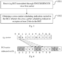
Fig. 2 is a flow chart illustrating steps of a cross-carrier scheduling method according to First Embodiment of the present disclosure; -
Fig. 3 is a flow chart I illustrating specific steps of the cross-carrier scheduling method according to the First Embodiment of the present disclosure; -
Fig. 4 is a schematic diagram illustrating scheduling of the transmission subframe structure under TDD configuration of 0 by using the cross-carrier scheduling method according to the First Embodiment of the present disclosure; -
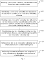
Fig. 5 is a flow chart II illustrating specific steps of the cross-carrier scheduling method according to the First Embodiment of the present disclosure; -
Fig. 6 is a flow chart illustrating steps of a cross-carrier scheduling method according to Second Embodiment of the present disclosure; -
Fig. 7 is a schematic diagram I illustrating scheduling of a transmission subframe structure under TDD configuration of 5 by using the cross-carrier scheduling method according to the First Embodiment of the present disclosure; -
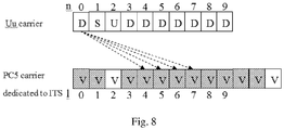
Fig. 8 is a schematic diagram II illustrating scheduling of the transmission subframe structure under TDD configuration of 5 by using the cross-carrier scheduling method according to the First Embodiment of the present disclosure; -
Fig. 9 is a flow chart illustrating specific steps of the cross-carrier scheduling method according to the Second Embodiment of the present disclosure; -
Fig. 10 is a schematic structural diagram of a cross-carrier scheduling device according to Third Embodiment of the present disclosure; and -
Fig. 11 is a schematic structural diagram of a cross-carrier scheduling device according to Fourth Embodiment of the present disclosure. - The technical solutions of the embodiments of the present disclosure will be described hereinafter in details in conjunction with the drawings of the embodiments of the present disclosure. Obviously, the embodiments described hereinafter are only some embodiments of the present disclosure, but do not include all the embodiments. Based on the embodiments of the present disclosure, all other embodiments obtained by those skilled in the art without any creative work should be considered to fall within the protection scope of the present disclosure.
- As shown in
Fig. 2 , a cross-carrier scheduling method according to First Embodiment of the present disclosure comprises: -
Step 101, receiving a cross-carrier scheduling indication transmitted from a base station via a first carrier; -
Step 102, determining a cross-carrier scheduling time indicated by the base station according to the cross-carrier scheduling indication; -
Step 103, adding a delay time to the cross-carrier scheduling time to obtain an actual cross-carrier scheduling time; and -
Step 104, performing communication between user equipment by using a second carrier during the actual cross-carrier scheduling time. - With Steps 101-104, user equipment UE (also called "terminal") receives a cross-carrier scheduling indication transmitted from a base station eNB via a first carrier used for communication with the eNB, then determines a cross-carrier scheduling time indicated by the eNB according to the cross-carrier scheduling indication, then adds a delay time to the cross-carrier scheduling time to obtain an actual cross-carrier scheduling time, and finally uses a second carrier, which is used for communication with other UE, to communicate during the actual cross-carrier scheduling time. By adding a delay time to the cross-carrier scheduling time as compensation, the scheduling time is increased in length, thereby improving system resource utilization.
- For example, UE communicates with eNB by means of TDD, the UE receives a cross-carrier scheduling indication under a Uu carrier; after obtaining an actual cross-carrier scheduling time, the UE communicates with other UE by using a resource of PC5 carrier dedicated to ITS during the actual cross-carrier scheduling time.
- Specifically, as shown in
Fig. 3 ,Step 101 comprises: -
Step 1011, receiving DCI transmitted through PDCCH/EPDCCH via a first carrier; and -
Step 1012, obtaining a cross-carrier scheduling indication carried in the DCI, wherein the cross-carrier scheduling indication occupies at least 2 bits in the DCI. - It can be known from the above that, in the embodiment, the cross-carrier scheduling indication is carried in the DCI, that is, the cross-carrier scheduling indication occupies at least 2 bits in the DCI. Since DCI is usually carried through PDCCH/EPDCCH, like
Steps - Taking the same example, the UE communicates with the eNB by means of TDD, as shown in Table 2, a cross-carrier scheduling time indicated by the base station may be further determined according to current TDD configuration (TDD configurations 0-6) and the received cross-carrier scheduling indication. If the current TDD configuration is 0, according to Tables 2 and 3, a transmission subframe structure is "DSUUUDSUUU" as shown in
Fig. 1 , when the received cross-carrier scheduling indication is in a downlink subframe D with a subframe number n=0, backward adjustment is made by k=4 subframes, that is, in a subframe with 1=4 pointed by an arrow, and it may be determined that the cross-carrier scheduling time indicated by the base station is in a subframe obtained by backward adjustment of k subframes. - As shown in
Fig. 2 , after the cross-carrier scheduling time is determined, the next step is to add a delay time to the cross-carrier scheduling time so as to obtain an actual cross-carrier scheduling time. - As mentioned above, the cross-carrier scheduling indication occupies at least 2 bits in the DCI, m subframes may be added based on backward adjustment of k subframes according to a value of bits occupied by the cross-carrier scheduling indication, that is, the UE communicates with other UE in a PC5 subframe corresponding to a Uu subframe with a subframe number of n+k+m. If the cross-carrier scheduling indication occupies 2 bits in the DCI, a value range of m is [0, 3] as shown in Table 4 below; and if the cross-carrier scheduling indication occupies 3 bits in the DCI, a value range of m is [0, 7].
Table 4 2 bits m 00 0 01 1 10 2 11 3 - It should be understood that not all of the downlink subframes and special subframes among Uu subframes have a cross-carrier scheduling function in the embodiment. In this case, it is possible to preset that the cross-carrier scheduling indication occupies 4 bits in the DCI, and correspondingly a value range of m is [0, 15], so that the downlink subframes D and special subframes S among Uu subframes, which have a cross-carrier scheduling function, will schedule all the PC5 subframes when m has a maximum value,.
- However, due to transmission subframe structures of the UE and the eNB, a time interval between two consecutive cross-carrier scheduling times indicated by the base station usually fails to reach some larger values of m, for example, there are only two subframes between PC5 subframes pointed by two adjacent solid arrows in
Fig. 4 . Therefore, as shown inFig. 5 , based on the above embodiment, there are following steps before Step 103: -
Step 105, obtaining a next cross-carrier scheduling time indicated by the base station according to a subframe number and a transmission subframe structure used for transmission of the cross-carrier scheduling indication; and -
Step 106, determining a value of a delay time according to a time interval between the cross-carrier scheduling time and the next cross-carrier scheduling time. - With
Steps Step 101, and then a value of a delay time is determined according to a time interval between the cross-carrier scheduling time and the next cross-carrier scheduling time, so as to actualize optimal utilization of system resources. - Referring still to the above example, the cross-carrier scheduling indication currently received is in the downlink subframe D with a subframe number n=0, and it is determined that the cross-carrier scheduling time indicated by the base station is in the subframe by backward adjustment of k=4 subframes, that is, in the subframe with 1=4 pointed by the arrow. In such case, according to a transmission subframe structure shown in
Fig. 4 , the next cross-carrier scheduling indication received is in a special subframe S with a subframe number n=1, and it is determined that the next cross-carrier scheduling time indicated by the base station is in the subframe by backward adjustment of k=6 subframes, that is, in a subframe with 1=7 pointed by an arrow. There is a time interval of only 2 subframes between the two cross-carrier scheduling times, so that a maximum value of m is 2, and a value range of m is [0, 2]. So, when the cross-carrier scheduling indication currently received is in the downlink subframe D with a subframe number n=0, UE may communicate with other UE by using PC5 resource in a PC5 subframe corresponding to a Uu subframe with a subframe number of n+k+m =0+4+m, that is, not only in a PC5 subframe with 1=4 but also in PC5 subframes with 1=5 and 1=6, which avoids repeated processing when m is limited to a maximum value. - Furthermore, in the embodiment, a length of the DCI is determined based on a sum of a basic information bit length under a maximum bandwidth and a preset scheduling bit length, and a maximum value of a maximum format length under a current bandwidth; wherein the basic information bit length is equal to a length of DCI format 5A, the maximum format length is equal to a length of
DCI format 0, and the preset scheduling bit length includes 3 bits of SPS configuration indication and 1 bit of SPS activation/release indication. - As shown in following Table 5 applicable to determination of a length of DCI under a bandwidth of 1.4 MHz, according to the above content, it is first determined that a basic information bit length (a length of DCI format 5A) is 20 bits under a maximum bandwidth of 20 MHz, and a preset scheduling bit length (3 bits of SPS configuration indication and 1 bit of SPS activation/release indication) is 4 bits, so that the sum is 24 bits; and a maximum format length (a length of DCI format 0) is 21 bits under the bandwidth of 1.4 MHz, so that the maximum value of 24 bits is taken as the length of DCI.
Table 5 Bandwidth 1.4 MHz 3 MHz 5 MHz 10 MHz 15 MHz 20 MHz Length of DCI format 5A (bit) 7 12 14 17 18 20 Length of DCI format 0/1A (bit)21 22 25 27 27 28 Length of DCI format (bit) 24 24 25 27 27 28 - In summary, according to the cross-carrier scheduling method of the First Embodiment of the present disclosure, after receiving a cross-carrier scheduling indication transmitted from the eNB via a first carrier, the UE determines a cross-carrier scheduling time indicated by the eNB according to the cross-carrier scheduling indication, then adds a delay time to the cross-carrier scheduling time indicated by the eNB to obtain an actual cross-carrier scheduling time, and finally uses a second carrier to communicate with other UE during the actual cross-carrier scheduling time. By adding a delay time to compensate for the cross-carrier scheduling time indicated by the eNB, the scheduling time is increased in length and idle resources are effectively used, thereby improving the system resource utilization. Certainly, the cross-carrier scheduling method of the embodiment may also be applied in FDD mode, which will not be described herein.
- As shown in
Fig. 6 , a cross-carrier scheduling method according to Second Embodiment of the present disclosure comprises: -
Step 201, receiving DCI transmitted through PDCCH/EPDCCH by all downlink subframes and special subframes via a first carrier; -
Step 202, obtaining a cross-carrier scheduling indication carried in the DCI, wherein the cross-carrier scheduling indication occupies at least 2 bits in the DCI; -
Step 203, determining a cross-carrier scheduling time indicated by the base station according to the cross-carrier scheduling indication; -
Step 204, adding a delay time to the cross-carrier scheduling time to obtain an actual cross-carrier scheduling time; and -
Step 205, performing communication between user equipment by using a second carrier during the actual cross-carrier scheduling time. - In the embodiment, all the downlink subframes and special subframes are entitled to a cross-carrier scheduling capability, in which case, with
Steps 201 to 205, UE communicates with eNB via a first carrier, and may receive DCI transmitted through PDCCH/EPDCCH by all the downlink subframes and special subframes via the first carrier, and obtain a cross-carrier scheduling indication carried in the DCI, then determine a cross-carrier scheduling time indicated by the eNB according to the cross-carrier scheduling indication, then add a delay time to the cross-carrier scheduling time to obtain an actual cross-carrier scheduling time, and finally use a second carrier, which is used for communication with other UE, to communicate during the actual cross-carrier scheduling time. By adding a delay time to the cross-carrier scheduling time as compensation, the scheduling time is increased in length, thereby improving the system resource utilization. - Taking the same example, UE communicates with eNB by means of TDD, the UE receives a cross-carrier scheduling indication under a Uu carrier; after obtaining an actual cross-carrier scheduling time, the UE communicates with other UE by use of a resource of PC5 carrier dedicated to ITS during the actual cross-carrier scheduling time. As indicated by dashed arrows in
Fig. 7 , all the downlink subframes and special subframes among Uu subframes under TDD configuration of 5 are capable of performing cross-carrier scheduling in corresponding PC5 subframes. - In the embodiment, cross-carrier scheduling based on the standards must be performed 4ms after the DCI sends a subframe, it is unnecessary to determine the cross-carrier scheduling time indicated by the base station according to Table 2 and the received cross-carrier scheduling indication, a cross-carrier scheduling time indicated by the base station corresponding to every cross-carrier scheduling indication is set to a fixed value instead, and a basic delay of cross-carrier scheduling is equal to 4 subframes, that is, k is fixed to 4, as indicated by the dashed arrows in
Fig. 7 . - As shown in
Fig. 6 , after the cross-carrier scheduling time is determined, the next step is to add a delay time to the cross-carrier scheduling time so as to obtain an actual cross-carrier scheduling time. - As in the First Embodiment, the cross-carrier scheduling indication occupies at least 2 bits in the DCI, m subframes may be added based on backward adjustment of 4 subframes according to a value of bits occupied by the cross-carrier scheduling indication, that is, the UE communicates with other UE in a PC5 subframe corresponding to a Uu subframe with a subframe number of n+4+m. If the cross-carrier scheduling indication occupies 2 bits in the DCI, a value range of m is [0, 3]; and if the cross-carrier scheduling indication occupies 3 bits in the DCI, a value range of m is [0, 7].
- In the embodiment, it is possible to preset that the cross-carrier scheduling indication occupies 2 bits in the DCI, and correspondingly a value range of m is [0, 3]. In such case, as shown in
Fig. 8 , a scheduling range of a Uu subframe with a subframe number n=0 covers PC5 subframes with 1=4 to 1=7, as indicated by dashed arrows inFig. 8 . Each of downlink subframes D and special subframes S among Uu subframes has a similar cross-carrier scheduling capability, so that all the PC5 subframes may be successfully covered by Uu through cross-carrier scheduling. - Similarly, due to the transmission subframe structures of UE and eNB, a time interval between two consecutive cross-carrier scheduling times indicated by the base station usually fails to reach some larger values of m, for example, there is no subframe between PC5 subframes pointed by two adjacent dashed arrows in
Fig. 7 . Therefore, as shown inFig. 9 , based on the above embodiment, there are following steps before Step 204: -
Step 206, obtaining a next cross-carrier scheduling time indicated by the base station according to a subframe number and a transmission subframe structure used for transmission of the cross-carrier scheduling indication; and -
Step 207, determining a value of a delay time according to a time interval between the cross-carrier scheduling time and the next cross-carrier scheduling time. - With
Steps Step 202, and then a value of a delay time is determined according to a time interval between the cross-carrier scheduling time and the next cross-carrier scheduling time, so as to actualize optimal utilization of system resources. - Referring still to the above example, the cross-carrier scheduling indication currently received is in the downlink subframe D with a subframe number n=0, and it is determined that the cross-carrier scheduling time indicated by the base station is in the subframe by backward adjustment of k=4 subframes, that is, in the subframe with 1=4 pointed by the arrow. In such case, according to a transmission subframe structure shown in Fig. 74, the next cross-carrier scheduling indication received is in a special subframe S with a subframe number n=1, and it is determined that the next cross-carrier scheduling time indicated by the base station is in the subframe by backward adjustment of k=4 subframes, that is, in a subframe with 1=5 pointed by an arrow. There is no subframe between the two cross-carrier scheduling times, so that a maximum value of m is 0, and m is equal to 0. So, when the cross-carrier scheduling indication currently received is in the downlink subframe D with a subframe number n=0, UE may communicate with other UE by use of PC5 resource in a PC5 subframe with 1=4 corresponding to a Uu subframe with a subframe number n+k+m=0+4+0, while communicate with other UE by using PC5 resource in a PC5 subframe with 1=5 with no delay according to the next cross-carrier scheduling indication, which avoids repeated processing.
- In summary, according to the cross-carrier scheduling method of the Second Embodiment of the present disclosure, the UE communicates with the eNB via a first carrier, and may receive DCI transmitted through PDCCH/EPDCCH by all the downlink subframes and special subframes via the first carrier, and obtain a cross-carrier scheduling indication carried in the DCI, then determine a cross-carrier scheduling time indicated by the eNB according to the cross-carrier scheduling indication, then add a delay time to the cross-carrier scheduling time to obtain an actual cross-carrier scheduling time, and finally use a second carrier, which is used for communication with other UE, to communicate during the actual cross-carrier scheduling time. By adding a delay time to the cross-carrier scheduling time as compensation, the scheduling time is increased in length and idle resources are effectively used, thereby improving the system resource utilization. Certainly, the cross-carrier scheduling method of the embodiment may also be applied in FDD mode, which will not be described herein.
- As shown in
Fig. 10 , a cross-carrier scheduling device according to Third Embodiment of the present disclosure comprises: - a
receiving module 1001, configured to receive a cross-carrier scheduling indication transmitted from a base station via a first carrier; - a
first determination module 1002, configured to determine a cross-carrier scheduling time indicated by the base station according to the cross-carrier scheduling indication; - a
first processing module 1003, configured to add a delay time to the cross-carrier scheduling time to obtain an actual cross-carrier scheduling time; and - a
communication module 1004, configured to perform communication between user equipment by using a second carrier during the actual cross-carrier scheduling time. - Wherein, the cross-carrier scheduling device further comprises:
- a second processing module, configured to obtain a next cross-carrier scheduling time indicated by the base station according to a subframe number and a transmission subframe structure used for transmission of the cross-carrier scheduling indication; and
- a second determination module, configured to determine a value of a delay time according to a time interval between the cross-carrier scheduling time and the next cross-carrier scheduling time.
- Wherein, the receiving module comprises:
- a receiving sub-module, configured to receive DCI transmitted through PDCCH/EPDCCH via a first carrier; and
- an acquisition sub-module, configured to obtain a cross-carrier scheduling indication carried in the DCI, wherein the cross-carrier scheduling indication occupies at least two bits in the DCI.
- Wherein, the receiving sub-module comprises:
a receiving unit, configured to receive DCI transmitted through PDCCH/EPDCCH by all downlink subframes and special subframes via a first carrier. - With the cross-carrier scheduling device of the Third Embodiment of the present disclosure, after receiving a cross-carrier scheduling indication transmitted from eNB via a first carrier, UE determines a cross-carrier scheduling time indicated by the base station according to the cross-carrier scheduling indication, then adds a delay time to the cross-carrier scheduling time indicated by the eNB to obtain an actual cross-carrier scheduling time, and finally uses a second carrier to communicate with other user equipment during the actual cross-carrier scheduling time. By adding a delay time to compensate for the cross-carrier scheduling time indicated by the eNB, the scheduling time is increased in length and idle resources are effectively used, thereby improving system resource utilization.
- It should be noted that the cross-carrier scheduling device provided by the Third Embodiment of the present disclosure is used for the aforesaid cross-carrier scheduling methods provided by the First Embodiment and the Second Embodiment, and may be used for all embodiments of the aforesaid cross-carrier scheduling methods, with same or similar beneficial effects being produced.
- For better achieving the above objective, as shown in
Fig. 11 , Fourth Embodiment of the present disclosure provides a cross-carrier scheduling device, comprising: aprocessor 1100, amemory 1120 connected with theprocessor 1100 through a bus interface, and atransceiver 1110 connected with theprocessor 1100 through the bus interface; the memory is configured to store programs and data used by the processor while performing operations;
thetransceiver 1110 is configured to receive a cross-carrier scheduling indication transmitted from a base station via a first carrier;
theprocessor 1100 is configured to determine a cross-carrier scheduling time indicated by the base station according to the cross-carrier scheduling indication;
theprocessor 1100 is further configured to add a delay time to the cross-carrier scheduling time to obtain an actual cross-carrier scheduling time; and
thetransceiver 1110 is further configured to perform communication between user equipment by using a second carrier during the actual cross-carrier scheduling time. - Wherein, in
Fig. 11 , bus architecture may include any number of interconnected buses and bridges, and specifically link together various circuits of one or more processors represented by theprocessor 1100 and a memory represented by thememory 1120. The bus architecture may further link together various other circuits of peripheral equipment, voltage stabilizers, power management circuits, and so on, which is well known in the art and thus will not be further described herein. The bus interface provides interfaces. Thetransceiver 1110 may be a plurality of components, that is, include transmitters and receivers, and provide units used for communication with other devices through transmission media. For different user equipment, auser interface 1130 may be interfaces capable of being externally and internally connected with required devices which include, but are not limited to, small keyboards, displays, speakers, microphones, and joysticks. Theprocessor 1100 is used for managing the bus architecture and general processing, and thememory 1120 may store the data used by theprocessor 1100 while performing operations. - It should be noted that the cross-carrier scheduling device provided by the Fourth Embodiment of the present disclosure is corresponding to the aforesaid cross-carrier scheduling device provided by the Third Embodiment, so that it may be used for all embodiments of the aforesaid cross-carrier scheduling methods provided by the First Embodiment and the Second Embodiment, with same or similar beneficial effects being produced.
- The above is preferred embodiments of the present disclosure. It should be noted that those of ordinary skill in the art may make various improvements and modifications without departing from the principle of the present disclosure, and these improvements and modifications shall be considered to fall into the protection scope of the present disclosure
Claims (12)
- A cross-carrier scheduling method, comprising:receiving a cross-carrier scheduling indication transmitted from a base station via a first carrier;determining a cross-carrier scheduling time indicated by the base station according to the cross-carrier scheduling indication;adding a delay time to the cross-carrier scheduling time to obtain an actual cross-carrier scheduling time; andperforming communication between user equipment by using a second carrier during the actual cross-carrier scheduling time.
- The cross-carrier scheduling method according to claim 1, wherein, before the step of adding a delay time to the cross-carrier scheduling time to obtain an actual cross-carrier scheduling time, the cross-carrier scheduling method further comprises:obtaining a next cross-carrier scheduling time indicated by the base station according to a subframe number and a transmission subframe structure used for transmission of the cross-carrier scheduling indication; anddetermining a value of the delay time according to a time interval between the cross-carrier scheduling time and the next cross-carrier scheduling time.
- The cross-carrier scheduling method according to claim 1, wherein the step of receiving a cross-carrier scheduling indication transmitted from a base station via the first carrier comprises:receiving Downlink Control Information (DCI) transmitted through Physical Downlink Control Channel (PDCCH)/Enhanced Physical Downlink Control Channel (EPDCCH) via the first carrier; andobtaining a cross-carrier scheduling indication carried in the DCI, wherein the cross-carrier scheduling indication occupies at least 2 bits in the DCI.
- The cross-carrier scheduling method according to claim 3, wherein the step of receiving DCI transmitted through PDCCH/EPDCCH via the first carrier comprises:
receiving DCI transmitted through PDCCH/EPDCCH by all downlink subframes and special subframes via the first carrier. - The cross-carrier scheduling method according to claim 3 or 4, wherein a length of the DCI is determined based on a sum of a basic information bit length under a maximum bandwidth and a preset scheduling bit length, and a maximum value of a maximum format length under a current bandwidth; wherein
the basic information bit length is equal to a length of DCI format 5A, the maximum format length is equal to a length of DCI format 0, and the preset scheduling bit length includes 3 bits of Semi-Persistent Scheduling (SPS) configuration indication and 1 bit of SPS activation/release indication. - A cross-carrier scheduling device, comprising:a receiving module, configured to receive a cross-carrier scheduling indication transmitted from a base station via the first carrier;a first determination module, configured to determine a cross-carrier scheduling time indicated by the base station according to the cross-carrier scheduling indication;a first processing module, configured to add a delay time to the cross-carrier scheduling time to obtain an actual cross-carrier scheduling time; anda communication module, configured to perform communication between user equipment by using a second carrier during the actual cross-carrier scheduling time.
- The cross-carrier scheduling device according to claim 6, further comprising:a second processing module, configured to obtain a next cross-carrier scheduling time indicated by the base station according to a subframe number and a transmission subframe structure used for transmission of the cross-carrier scheduling indication; anda second determination module, configured to determine a value of the delay time according to a time interval between the cross-carrier scheduling time and the next cross-carrier scheduling time.
- The cross-carrier scheduling device according to claim 6, wherein the receiving module comprises:a receiving sub-module, configured to receive DCI transmitted through PDCCH/EPDCCH via the first carrier; andan acquisition sub-module, configured to obtain a cross-carrier scheduling indication carried in the DCI, wherein the cross-carrier scheduling indication occupies at least two bits in the DCI.
- The cross-carrier scheduling device according to claim 8, wherein the receiving sub-module comprises:
a receiving unit, configured to receive DCI transmitted through PDCCH/EPDCCH by all downlink subframes and special subframes via the first carrier. - The cross-carrier scheduling device according to claim 8 or 9, wherein a length of the DCI is determined based on a sum of a basic information bit length under a maximum bandwidth and a preset scheduling bit length, and a maximum value of a maximum format length under a current bandwidth; wherein
the basic information bit length is equal to a length of DCI format 5A, the maximum format length is equal to a length of DCI format 0, and the preset scheduling bit length includes 3 bits of SPS configuration indication and 1 bit of SPS activation/release indication. - A cross-carrier scheduling device, comprising a transceiver, a processor, and a memory configured to store programs or data used by the processor while performing operations, wherein:the transceiver is configured to receive a cross-carrier scheduling indication transmitted from a base station via the first carrier;the processor is configured to determine a cross-carrier scheduling time indicated by the base station according to the cross-carrier scheduling indication, and add a delay time to the cross-carrier scheduling time to obtain an actual cross-carrier scheduling time; andthe transceiver is further configured to perform communication between user equipment by using a second carrier during the actual cross-carrier scheduling time obtained by the processor.
- A computer readable storage medium, on which is stored instructions for executing following steps:receiving a cross-carrier scheduling indication transmitted from a base station via the first carrier;determining a cross-carrier scheduling time indicated by the base station according to the cross-carrier scheduling indication;adding a delay time to the cross-carrier scheduling time to obtain an actual cross-carrier scheduling time; andperforming communication between user equipment by using a second carrier during the actual cross-carrier scheduling time.
Applications Claiming Priority (2)
| Application Number | Priority Date | Filing Date | Title |
|---|---|---|---|
| CN201610963586.0A CN108024379B (en) | 2016-11-04 | 2016-11-04 | A method and device for cross-carrier scheduling |
| PCT/CN2017/108865 WO2018082553A1 (en) | 2016-11-04 | 2017-11-01 | Cross-carrier scheduling method and device |
Publications (3)
| Publication Number | Publication Date |
|---|---|
| EP3537645A1 true EP3537645A1 (en) | 2019-09-11 |
| EP3537645A4 EP3537645A4 (en) | 2019-10-30 |
| EP3537645B1 EP3537645B1 (en) | 2021-02-24 |
Family
ID=62076598
Family Applications (1)
| Application Number | Title | Priority Date | Filing Date |
|---|---|---|---|
| EP17867695.3A Active EP3537645B1 (en) | 2016-11-04 | 2017-11-01 | Cross-carrier scheduling method and device |
Country Status (7)
| Country | Link |
|---|---|
| US (1) | US11129177B2 (en) |
| EP (1) | EP3537645B1 (en) |
| JP (1) | JP6898035B2 (en) |
| KR (1) | KR102207118B1 (en) |
| CN (1) | CN108024379B (en) |
| TW (1) | TWI654868B (en) |
| WO (1) | WO2018082553A1 (en) |
Families Citing this family (5)
| Publication number | Priority date | Publication date | Assignee | Title |
|---|---|---|---|---|
| BR112020024169A2 (en) | 2018-06-29 | 2021-03-02 | Guangdong Oppo Mobile Telecommunications Corp., Ltd. | method for data transmission, terminal device, chip and computer-readable storage media |
| US10887904B2 (en) | 2018-08-10 | 2021-01-05 | Qualcomm Incorporated | Cross-carrier scheduling enhancements in new radio (NR) |
| US11877292B2 (en) * | 2020-07-29 | 2024-01-16 | Qualcomm Incorporated | Techniques for activating and releasing resources across multiple component carriers |
| WO2022031147A1 (en) * | 2020-08-07 | 2022-02-10 | 엘지전자 주식회사 | Method and apparatus for performing nr sidelink communication on lte carrier |
| CN113825192B (en) * | 2021-11-22 | 2022-03-08 | 深圳传音控股股份有限公司 | Processing method, communication device, communication system, and storage medium |
Family Cites Families (11)
| Publication number | Priority date | Publication date | Assignee | Title |
|---|---|---|---|---|
| US9515808B2 (en) * | 2011-07-26 | 2016-12-06 | Qualcomm Incorporated | Transmission of control information in a wireless network with carrier aggregation |
| CN103327618B (en) * | 2012-03-20 | 2016-01-20 | 上海贝尔股份有限公司 | For across in carrier dispatching situation from carrier resource management method and equipment |
| US9554393B2 (en) | 2012-04-19 | 2017-01-24 | Lg Electronics Inc. | Method for transmitting control information for direct D2D communication in wireless communication systems, and apparatus for same |
| CN103844701A (en) * | 2012-12-04 | 2014-06-11 | 宜城市第三高级中学 | Bed with waist pad |
| US9900142B2 (en) * | 2013-06-26 | 2018-02-20 | Lg Electronics Inc. | Method and apparatus for FDD/TDD intra-node and inter-node carrier aggregation |
| CN103944701B (en) * | 2013-08-26 | 2017-08-08 | 上海朗帛通信技术有限公司 | Transmission method and device in a kind of TDD FDD association systems |
| EP3817270B1 (en) * | 2014-11-20 | 2023-09-20 | Panasonic Intellectual Property Corporation of America | Improved csi reporting for unlicensed carriers from a mobile station to a base station |
| EP3038285B1 (en) * | 2014-12-22 | 2022-04-27 | Industrial Technology Research Institute | Method of handling communication operation in communication system and related apparatus |
| KR102000968B1 (en) | 2015-01-02 | 2019-07-17 | 엘지전자 주식회사 | A method for transmitting a D2D signal in a wireless communication system and a terminal using the same |
| WO2016171471A1 (en) | 2015-04-20 | 2016-10-27 | 엘지전자 주식회사 | Method for d2d operation performed by terminal in wireless communication system, and terminal using same |
| CN105188045B (en) | 2015-09-08 | 2018-11-06 | 宇龙计算机通信科技(深圳)有限公司 | D2D for vehicle communication has found method, apparatus and terminal |
-
2016
- 2016-11-04 CN CN201610963586.0A patent/CN108024379B/en active Active
-
2017
- 2017-11-01 WO PCT/CN2017/108865 patent/WO2018082553A1/en not_active Ceased
- 2017-11-01 KR KR1020197015568A patent/KR102207118B1/en active Active
- 2017-11-01 EP EP17867695.3A patent/EP3537645B1/en active Active
- 2017-11-01 US US16/346,688 patent/US11129177B2/en active Active
- 2017-11-01 JP JP2019522547A patent/JP6898035B2/en active Active
- 2017-11-01 TW TW106137709A patent/TWI654868B/en active
Also Published As
| Publication number | Publication date |
|---|---|
| JP6898035B2 (en) | 2021-07-07 |
| US20190281612A1 (en) | 2019-09-12 |
| US11129177B2 (en) | 2021-09-21 |
| CN108024379A (en) | 2018-05-11 |
| EP3537645A4 (en) | 2019-10-30 |
| JP2020511011A (en) | 2020-04-09 |
| WO2018082553A1 (en) | 2018-05-11 |
| TWI654868B (en) | 2019-03-21 |
| EP3537645B1 (en) | 2021-02-24 |
| CN108024379B (en) | 2019-08-30 |
| TW201818683A (en) | 2018-05-16 |
| KR102207118B1 (en) | 2021-01-22 |
| KR20190073524A (en) | 2019-06-26 |
Similar Documents
| Publication | Publication Date | Title |
|---|---|---|
| EP2720504B1 (en) | Communication methods and devices in time division duplex system | |
| US11818701B2 (en) | Apparatus and method for decoding a PDSCH using pre-emption | |
| EP3439390B1 (en) | Information feedback method, base station, terminal, and storage medium | |
| EP3537645B1 (en) | Cross-carrier scheduling method and device | |
| AU2017405380A1 (en) | Control signalling transmission method, base station and terminal | |
| EP3496480B1 (en) | Method, apparatus and system for sending control information | |
| CN115334678B (en) | Shared channel scheduling method, device, terminal and network side equipment | |
| EP4307802A1 (en) | Uplink transmission method and apparatus, and terminal | |
| EP3522636A1 (en) | Medium access control layer structure, data transmission method, network equipment, and terminal | |
| EP3032901A1 (en) | Information transmission method and device | |
| EP3179652A1 (en) | Method for controlling transmission of channel state information, base station, terminal and storage medium | |
| WO2022012433A1 (en) | Harq-ack feedback method and device | |
| EP3468085B1 (en) | Subframe type notification and determination methods and device | |
| CN113285789B (en) | Resource indication method and device of auxiliary link control information and terminal equipment | |
| EP3544216B1 (en) | Information transmission method and device | |
| EP3982672A1 (en) | Wireless communication method, device and system | |
| EP4451780A1 (en) | Method and apparatus of controlling uplink transmission in wireless communication system | |
| CN111865507B (en) | Processing method and device of HARQ (hybrid automatic repeat request) process mode, related equipment and storage medium | |
| EP2863697A1 (en) | Method, device, and communication for transmission control | |
| KR20210138757A (en) | Communication method and device | |
| CN103580833B (en) | A kind of method and apparatus for configuring carrier wave polymerization | |
| EP4456645A1 (en) | Method and apparatus of controlling uplink transmission in wireless communication system | |
| EP3500030A1 (en) | Transmission method, device, mobile communication terminal and network-side equipment | |
| EP4525340A1 (en) | Method and apparatus for determining candidate pdsch receiving occasion, and related device | |
| EP3413493A1 (en) | Method and device for dynamically determining pilot pattern |
Legal Events
| Date | Code | Title | Description |
|---|---|---|---|
| STAA | Information on the status of an ep patent application or granted ep patent |
Free format text: STATUS: THE INTERNATIONAL PUBLICATION HAS BEEN MADE |
|
| PUAI | Public reference made under article 153(3) epc to a published international application that has entered the european phase |
Free format text: ORIGINAL CODE: 0009012 |
|
| STAA | Information on the status of an ep patent application or granted ep patent |
Free format text: STATUS: REQUEST FOR EXAMINATION WAS MADE |
|
| 17P | Request for examination filed |
Effective date: 20190507 |
|
| AK | Designated contracting states |
Kind code of ref document: A1 Designated state(s): AL AT BE BG CH CY CZ DE DK EE ES FI FR GB GR HR HU IE IS IT LI LT LU LV MC MK MT NL NO PL PT RO RS SE SI SK SM TR |
|
| AX | Request for extension of the european patent |
Extension state: BA ME |
|
| A4 | Supplementary search report drawn up and despatched |
Effective date: 20190926 |
|
| RIC1 | Information provided on ipc code assigned before grant |
Ipc: H04L 5/00 20060101AFI20190920BHEP Ipc: H04W 72/12 20090101ALI20190920BHEP |
|
| DAV | Request for validation of the european patent (deleted) | ||
| DAX | Request for extension of the european patent (deleted) | ||
| GRAP | Despatch of communication of intention to grant a patent |
Free format text: ORIGINAL CODE: EPIDOSNIGR1 |
|
| STAA | Information on the status of an ep patent application or granted ep patent |
Free format text: STATUS: GRANT OF PATENT IS INTENDED |
|
| INTG | Intention to grant announced |
Effective date: 20200917 |
|
| GRAS | Grant fee paid |
Free format text: ORIGINAL CODE: EPIDOSNIGR3 |
|
| GRAA | (expected) grant |
Free format text: ORIGINAL CODE: 0009210 |
|
| STAA | Information on the status of an ep patent application or granted ep patent |
Free format text: STATUS: THE PATENT HAS BEEN GRANTED |
|
| AK | Designated contracting states |
Kind code of ref document: B1 Designated state(s): AL AT BE BG CH CY CZ DE DK EE ES FI FR GB GR HR HU IE IS IT LI LT LU LV MC MK MT NL NO PL PT RO RS SE SI SK SM TR |
|
| REG | Reference to a national code |
Ref country code: CH Ref legal event code: EP |
|
| REG | Reference to a national code |
Ref country code: AT Ref legal event code: REF Ref document number: 1365849 Country of ref document: AT Kind code of ref document: T Effective date: 20210315 |
|
| REG | Reference to a national code |
Ref country code: IE Ref legal event code: FG4D |
|
| REG | Reference to a national code |
Ref country code: DE Ref legal event code: R096 Ref document number: 602017033553 Country of ref document: DE |
|
| REG | Reference to a national code |
Ref country code: LT Ref legal event code: MG9D |
|
| REG | Reference to a national code |
Ref country code: NL Ref legal event code: MP Effective date: 20210224 |
|
| PG25 | Lapsed in a contracting state [announced via postgrant information from national office to epo] |
Ref country code: FI Free format text: LAPSE BECAUSE OF FAILURE TO SUBMIT A TRANSLATION OF THE DESCRIPTION OR TO PAY THE FEE WITHIN THE PRESCRIBED TIME-LIMIT Effective date: 20210224 Ref country code: GR Free format text: LAPSE BECAUSE OF FAILURE TO SUBMIT A TRANSLATION OF THE DESCRIPTION OR TO PAY THE FEE WITHIN THE PRESCRIBED TIME-LIMIT Effective date: 20210525 Ref country code: HR Free format text: LAPSE BECAUSE OF FAILURE TO SUBMIT A TRANSLATION OF THE DESCRIPTION OR TO PAY THE FEE WITHIN THE PRESCRIBED TIME-LIMIT Effective date: 20210224 Ref country code: NO Free format text: LAPSE BECAUSE OF FAILURE TO SUBMIT A TRANSLATION OF THE DESCRIPTION OR TO PAY THE FEE WITHIN THE PRESCRIBED TIME-LIMIT Effective date: 20210524 Ref country code: PT Free format text: LAPSE BECAUSE OF FAILURE TO SUBMIT A TRANSLATION OF THE DESCRIPTION OR TO PAY THE FEE WITHIN THE PRESCRIBED TIME-LIMIT Effective date: 20210624 Ref country code: BG Free format text: LAPSE BECAUSE OF FAILURE TO SUBMIT A TRANSLATION OF THE DESCRIPTION OR TO PAY THE FEE WITHIN THE PRESCRIBED TIME-LIMIT Effective date: 20210524 Ref country code: LT Free format text: LAPSE BECAUSE OF FAILURE TO SUBMIT A TRANSLATION OF THE DESCRIPTION OR TO PAY THE FEE WITHIN THE PRESCRIBED TIME-LIMIT Effective date: 20210224 |
|
| REG | Reference to a national code |
Ref country code: DE Ref legal event code: R081 Ref document number: 602017033553 Country of ref document: DE Owner name: DATANG MOBILE COMMUNICATIONS EQUIPMENT CO., LT, CN Free format text: FORMER OWNER: CHINA ACADEMY OF TELECOMMUNICATIONS TECHNOLOGY, BEIJING, CN |
|
| REG | Reference to a national code |
Ref country code: AT Ref legal event code: MK05 Ref document number: 1365849 Country of ref document: AT Kind code of ref document: T Effective date: 20210224 |
|
| REG | Reference to a national code |
Ref country code: GB Ref legal event code: 732E Free format text: REGISTERED BETWEEN 20210729 AND 20210804 |
|
| PG25 | Lapsed in a contracting state [announced via postgrant information from national office to epo] |
Ref country code: LV Free format text: LAPSE BECAUSE OF FAILURE TO SUBMIT A TRANSLATION OF THE DESCRIPTION OR TO PAY THE FEE WITHIN THE PRESCRIBED TIME-LIMIT Effective date: 20210224 Ref country code: PL Free format text: LAPSE BECAUSE OF FAILURE TO SUBMIT A TRANSLATION OF THE DESCRIPTION OR TO PAY THE FEE WITHIN THE PRESCRIBED TIME-LIMIT Effective date: 20210224 Ref country code: NL Free format text: LAPSE BECAUSE OF FAILURE TO SUBMIT A TRANSLATION OF THE DESCRIPTION OR TO PAY THE FEE WITHIN THE PRESCRIBED TIME-LIMIT Effective date: 20210224 Ref country code: RS Free format text: LAPSE BECAUSE OF FAILURE TO SUBMIT A TRANSLATION OF THE DESCRIPTION OR TO PAY THE FEE WITHIN THE PRESCRIBED TIME-LIMIT Effective date: 20210224 Ref country code: SE Free format text: LAPSE BECAUSE OF FAILURE TO SUBMIT A TRANSLATION OF THE DESCRIPTION OR TO PAY THE FEE WITHIN THE PRESCRIBED TIME-LIMIT Effective date: 20210224 |
|
| PG25 | Lapsed in a contracting state [announced via postgrant information from national office to epo] |
Ref country code: IS Free format text: LAPSE BECAUSE OF FAILURE TO SUBMIT A TRANSLATION OF THE DESCRIPTION OR TO PAY THE FEE WITHIN THE PRESCRIBED TIME-LIMIT Effective date: 20210624 |
|
| PG25 | Lapsed in a contracting state [announced via postgrant information from national office to epo] |
Ref country code: SM Free format text: LAPSE BECAUSE OF FAILURE TO SUBMIT A TRANSLATION OF THE DESCRIPTION OR TO PAY THE FEE WITHIN THE PRESCRIBED TIME-LIMIT Effective date: 20210224 Ref country code: AT Free format text: LAPSE BECAUSE OF FAILURE TO SUBMIT A TRANSLATION OF THE DESCRIPTION OR TO PAY THE FEE WITHIN THE PRESCRIBED TIME-LIMIT Effective date: 20210224 Ref country code: CZ Free format text: LAPSE BECAUSE OF FAILURE TO SUBMIT A TRANSLATION OF THE DESCRIPTION OR TO PAY THE FEE WITHIN THE PRESCRIBED TIME-LIMIT Effective date: 20210224 Ref country code: EE Free format text: LAPSE BECAUSE OF FAILURE TO SUBMIT A TRANSLATION OF THE DESCRIPTION OR TO PAY THE FEE WITHIN THE PRESCRIBED TIME-LIMIT Effective date: 20210224 |
|
| REG | Reference to a national code |
Ref country code: DE Ref legal event code: R097 Ref document number: 602017033553 Country of ref document: DE |
|
| PG25 | Lapsed in a contracting state [announced via postgrant information from national office to epo] |
Ref country code: SK Free format text: LAPSE BECAUSE OF FAILURE TO SUBMIT A TRANSLATION OF THE DESCRIPTION OR TO PAY THE FEE WITHIN THE PRESCRIBED TIME-LIMIT Effective date: 20210224 Ref country code: DK Free format text: LAPSE BECAUSE OF FAILURE TO SUBMIT A TRANSLATION OF THE DESCRIPTION OR TO PAY THE FEE WITHIN THE PRESCRIBED TIME-LIMIT Effective date: 20210224 Ref country code: RO Free format text: LAPSE BECAUSE OF FAILURE TO SUBMIT A TRANSLATION OF THE DESCRIPTION OR TO PAY THE FEE WITHIN THE PRESCRIBED TIME-LIMIT Effective date: 20210224 |
|
| PLBE | No opposition filed within time limit |
Free format text: ORIGINAL CODE: 0009261 |
|
| STAA | Information on the status of an ep patent application or granted ep patent |
Free format text: STATUS: NO OPPOSITION FILED WITHIN TIME LIMIT |
|
| PG25 | Lapsed in a contracting state [announced via postgrant information from national office to epo] |
Ref country code: ES Free format text: LAPSE BECAUSE OF FAILURE TO SUBMIT A TRANSLATION OF THE DESCRIPTION OR TO PAY THE FEE WITHIN THE PRESCRIBED TIME-LIMIT Effective date: 20210224 Ref country code: AL Free format text: LAPSE BECAUSE OF FAILURE TO SUBMIT A TRANSLATION OF THE DESCRIPTION OR TO PAY THE FEE WITHIN THE PRESCRIBED TIME-LIMIT Effective date: 20210224 |
|
| 26N | No opposition filed |
Effective date: 20211125 |
|
| PG25 | Lapsed in a contracting state [announced via postgrant information from national office to epo] |
Ref country code: SI Free format text: LAPSE BECAUSE OF FAILURE TO SUBMIT A TRANSLATION OF THE DESCRIPTION OR TO PAY THE FEE WITHIN THE PRESCRIBED TIME-LIMIT Effective date: 20210224 |
|
| PG25 | Lapsed in a contracting state [announced via postgrant information from national office to epo] |
Ref country code: IT Free format text: LAPSE BECAUSE OF FAILURE TO SUBMIT A TRANSLATION OF THE DESCRIPTION OR TO PAY THE FEE WITHIN THE PRESCRIBED TIME-LIMIT Effective date: 20210224 |
|
| PG25 | Lapsed in a contracting state [announced via postgrant information from national office to epo] |
Ref country code: IS Free format text: LAPSE BECAUSE OF FAILURE TO SUBMIT A TRANSLATION OF THE DESCRIPTION OR TO PAY THE FEE WITHIN THE PRESCRIBED TIME-LIMIT Effective date: 20210624 |
|
| PG25 | Lapsed in a contracting state [announced via postgrant information from national office to epo] |
Ref country code: MC Free format text: LAPSE BECAUSE OF FAILURE TO SUBMIT A TRANSLATION OF THE DESCRIPTION OR TO PAY THE FEE WITHIN THE PRESCRIBED TIME-LIMIT Effective date: 20210224 |
|
| REG | Reference to a national code |
Ref country code: CH Ref legal event code: PL |
|
| PG25 | Lapsed in a contracting state [announced via postgrant information from national office to epo] |
Ref country code: LU Free format text: LAPSE BECAUSE OF NON-PAYMENT OF DUE FEES Effective date: 20211101 Ref country code: BE Free format text: LAPSE BECAUSE OF NON-PAYMENT OF DUE FEES Effective date: 20211130 |
|
| REG | Reference to a national code |
Ref country code: BE Ref legal event code: MM Effective date: 20211130 |
|
| PG25 | Lapsed in a contracting state [announced via postgrant information from national office to epo] |
Ref country code: IE Free format text: LAPSE BECAUSE OF NON-PAYMENT OF DUE FEES Effective date: 20211101 |
|
| P01 | Opt-out of the competence of the unified patent court (upc) registered |
Effective date: 20230512 |
|
| PG25 | Lapsed in a contracting state [announced via postgrant information from national office to epo] |
Ref country code: CY Free format text: LAPSE BECAUSE OF FAILURE TO SUBMIT A TRANSLATION OF THE DESCRIPTION OR TO PAY THE FEE WITHIN THE PRESCRIBED TIME-LIMIT Effective date: 20210224 |
|
| PG25 | Lapsed in a contracting state [announced via postgrant information from national office to epo] |
Ref country code: LI Free format text: LAPSE BECAUSE OF NON-PAYMENT OF DUE FEES Effective date: 20220630 Ref country code: HU Free format text: LAPSE BECAUSE OF FAILURE TO SUBMIT A TRANSLATION OF THE DESCRIPTION OR TO PAY THE FEE WITHIN THE PRESCRIBED TIME-LIMIT; INVALID AB INITIO Effective date: 20171101 Ref country code: CH Free format text: LAPSE BECAUSE OF NON-PAYMENT OF DUE FEES Effective date: 20220630 |
|
| PG25 | Lapsed in a contracting state [announced via postgrant information from national office to epo] |
Ref country code: MK Free format text: LAPSE BECAUSE OF FAILURE TO SUBMIT A TRANSLATION OF THE DESCRIPTION OR TO PAY THE FEE WITHIN THE PRESCRIBED TIME-LIMIT Effective date: 20210224 |
|
| PG25 | Lapsed in a contracting state [announced via postgrant information from national office to epo] |
Ref country code: MT Free format text: LAPSE BECAUSE OF FAILURE TO SUBMIT A TRANSLATION OF THE DESCRIPTION OR TO PAY THE FEE WITHIN THE PRESCRIBED TIME-LIMIT Effective date: 20210224 |
|
| PG25 | Lapsed in a contracting state [announced via postgrant information from national office to epo] |
Ref country code: TR Free format text: LAPSE BECAUSE OF FAILURE TO SUBMIT A TRANSLATION OF THE DESCRIPTION OR TO PAY THE FEE WITHIN THE PRESCRIBED TIME-LIMIT Effective date: 20210224 |
|
| PGFP | Annual fee paid to national office [announced via postgrant information from national office to epo] |
Ref country code: DE Payment date: 20251119 Year of fee payment: 9 |
|
| PGFP | Annual fee paid to national office [announced via postgrant information from national office to epo] |
Ref country code: GB Payment date: 20251121 Year of fee payment: 9 |
|
| PGFP | Annual fee paid to national office [announced via postgrant information from national office to epo] |
Ref country code: FR Payment date: 20251126 Year of fee payment: 9 |