EP3537602A1 - A method of pv panels diagnostic in pv panels system - Google Patents
A method of pv panels diagnostic in pv panels system Download PDFInfo
- Publication number
- EP3537602A1 EP3537602A1 EP18460014.6A EP18460014A EP3537602A1 EP 3537602 A1 EP3537602 A1 EP 3537602A1 EP 18460014 A EP18460014 A EP 18460014A EP 3537602 A1 EP3537602 A1 EP 3537602A1
- Authority
- EP
- European Patent Office
- Prior art keywords
- fingerprints
- panels
- value
- pair
- panel
- Prior art date
- Legal status (The legal status is an assumption and is not a legal conclusion. Google has not performed a legal analysis and makes no representation as to the accuracy of the status listed.)
- Granted
Links
Images


Classifications
-
- H—ELECTRICITY
- H02—GENERATION; CONVERSION OR DISTRIBUTION OF ELECTRIC POWER
- H02S—GENERATION OF ELECTRIC POWER BY CONVERSION OF INFRARED RADIATION, VISIBLE LIGHT OR ULTRAVIOLET LIGHT, e.g. USING PHOTOVOLTAIC [PV] MODULES
- H02S50/00—Monitoring or testing of PV systems, e.g. load balancing or fault identification
-
- Y—GENERAL TAGGING OF NEW TECHNOLOGICAL DEVELOPMENTS; GENERAL TAGGING OF CROSS-SECTIONAL TECHNOLOGIES SPANNING OVER SEVERAL SECTIONS OF THE IPC; TECHNICAL SUBJECTS COVERED BY FORMER USPC CROSS-REFERENCE ART COLLECTIONS [XRACs] AND DIGESTS
- Y02—TECHNOLOGIES OR APPLICATIONS FOR MITIGATION OR ADAPTATION AGAINST CLIMATE CHANGE
- Y02E—REDUCTION OF GREENHOUSE GAS [GHG] EMISSIONS, RELATED TO ENERGY GENERATION, TRANSMISSION OR DISTRIBUTION
- Y02E10/00—Energy generation through renewable energy sources
- Y02E10/50—Photovoltaic [PV] energy
Definitions
- the subject of the invention is a method of PV panels diagnostic in PV panels system using a solar inverter for detecting at least one failed panel in the photovoltaic power generators.
- the solar inverter have been used for converting DC current generated in PV panels into AC current for feeding the electrical grid network.
- EP 1403649 patent application there is known the method and the device for fault diagnosis of photovoltaic generators of a PV installation during a feed-in operation.
- Many different kind of inverters are used in this aim.
- the inverter comprises an input side for connecting at least one PV generator comprising one or more solar modules; an output side for feeding into the grid, at least one energy storage device, diodes and semiconductor switches for generating the output -side AC voltage; microcontroller at least for controlling the semiconductor switches and measurement for detecting the electrical input and output parameters for controlling the solar inverter.
- the microcontroller is adapted to generate current- voltage characteristic measured during the operation of the inverter connected to the PV generator.
- the microcontroller can switch off the failured PV module.
- current and voltage of the PV generator must be measured in order to create the current-voltage characteristic.
- the measurement the current and voltage is also necessary during the monitoring DC link capacitance in a power inverter which is known from the international application WO2015/165574 .
- an indicator ESR Equivalent Series Resistance
- the presented invention provides a method for PV Panel diagnostic system in solar inverter according to claims 1-5.
- the main advantage of the solution according to the invention is that it allows for indication which solar panel is either in normal or faulty condition by using only DC link measuring device what is very convenient and practical from a technical point of view.
- a PV panels system 1 which contains PV Panels 2 with single panels p11 .. p1n; p21.. p2n; ....pn1..pnn (where n is a natural number) of the possible known kinds, connected in possible known ways (e.g. series or parallel).
- the PV panels system 1 is connected through their outputs A and B with a solar inverter circuit 3 having an inverter unit 4 connected parallel with a DC link unit 5.
- the inverter circuit 3 comprises a solar inverter control unit 6 connected electrically with a PV panels monitoring unit 7.
- the solar inverter control unit 6 and the PV panels monitoring unit 7 may be combined in single unit what is not presented in the drawing.
- the inverter unit 4 has at least two solid state switches, forming an inverter switching leg for each phase a, b, c, for converting DC input voltage from the panel system 1 into AC output voltage.
- the solid state switches of the inverter unit 4 are chosen from any of the possible known kinds - e.g. diodes, transistors, thyristors, etc.
- the DC link unit 5 comprises at least one DC link circuit 8 and a DC link voltage measuring device 9.
- DC link circuit 8 comprises capacitor C and an equivalent of series resistance ESR.
- the inverter control unit 6 is a computer device, having a data acquisition module 10 for receiving and processing input signals from voltage signals U DC of DC link unit 5, measured by the sensor 9 connected to the circuit 8.
- the inverter control unit 6 is also equipped with an output module 11 for generating switching signals for solid switches 4a, 4b, 4c of the inverter unit 4.
- the inverter control unit 6 is also equipped with an alarm generating module 12 for gathered the data received from the PV panels monitoring unit 7, e.g. capacitance C of the DC link, the value of ESR (Equivalent Series Resistance) and the voltage values of measured signals U DC and for generating alarm dependent on the value of the fault indicator F ind .
- the PV panels monitoring unit 7 is a computer device, having processing unit 13 for receiving and processing input signals i.e. voltage U DC of DC link unit 5.
- the PV panels monitoring unit 7 is equipped with a fault indicator module 14 for calculating a fault indicator F ind .
- the fault indicator module 14 is connected with an indication PV panels module 15.
- the inventive method is implemented according to the following steps 1-6:
- Step S1 Measuring voltage signal U DC1
- a voltage initial signal U DC1 of the DC link circuit 8 is measured by the DC link voltage measuring device 9.
- SetF i.e. 1/82000 Hz.
- Step S2 Processing measured signal U DC1
- the voltage initial signal U DC1 is processed in order to obtain a fingerprints F1....Fn of the measured signal. This is done by performing a spectral analysis of the signal U DC1 by using a FFT (Fast Fourier Transform) process and from the characteristic frequencies of FFT(U DC1 ) signal amplitudes SigAMPfin(U DC1 ) of each fingerprint what is calculated in the known way, using the PV panels monitoring unit 7.
- the fingerprints with signals amplitudes for the set of frequencies SetF given by the user is stored in the fault indication module 14.
- Exemplary embodiment of the finger measurement is presented in fig. 5 and in a table 1. Table 1.
- Step S3 Measuring a consecutive voltage signal U DC2
- a consecutive voltage signal U DC2 of the DC link circuit 8 is measured by the DC link voltage measuring device 9.
- the consecutive voltage signal is indicated as U DCn , wherein for the previously measured signal (n-1) the indication is presented as U DCn-1 .
- Step S4 Processing measured signal U DC2
- the consecutive voltage signal U DC2 is processed in order to obtain fingerprints F11 VietnameseFnn of the measured signal. This is done by performing a spectral analysis of the signal U DC2 by using a FFT (Fast Fourier Transform) process and from the characteristic frequencies of FFT(U DC2 ) signal amplitudes SigAMPfin(U DC2 ) of each fingerprint what is calculated in the known way, using the PV panels monitoring unit 7.
- the fingerprints with signals amplitudes for the set of frequencies SetF given by the user is stored in the fault indication module 14.
- the PV panels monitoring unit 7 stores the amplitudes values of a chosen SetF set of frequencies amplitudes, given by the user in step 1, i.e.
- Step S5 Settlement the fault indicator F ind
- step 5 a process of a settlement of the fault indicator F ind is performed by comparing the values of signal consecutive amplitudes SigAMPcon(U DC2 ) with the value of the signal amplitudes SigAMPfin(U DC1 ) of the characteristic frequencies of Fast Fourier Transform FFT(U DC1 ) of the voltage U DC1 of DC link unit 5 calculated in the step 2 taking into account the data delivered in the step S1.
- the percentage difference between the values of signal consecutive amplitudes SigAMPcon(U DC2 ) and the value of the signal amplitudes SigAMPfin(U DC1 ) is the fault indicator F ind for each pair of fingerprints F1, F11; F2, F22; whereasFn, Fnn.
- the sensitive indicator Senlnd was established as 20% of frequency amplitudes
- the warning indicator Warlnd is established as 15 %
- the alarm indicator Alarlnd was established as 30 %.
- the indicator F ind is automatically transmitted from the PV panels monitoring unit 7 to the inverter control unit 6.
- the inverter control unit 6 may send the warn signal command or the stop command signal to the inverter unit 4 via the output module 11.
- step S6 After the decision is made by the system additional analysis of amplitudes values in module is made in step S6. If there is no alarm in step S5 the procedure goes back to step S3.
- Step S6 Indication of the failed panels
- the information on which panels is stored in the indication PV panels module 15 in a table PanelNums for next usage in an upper level diagnostic system or by service personnel, what is not presented in the drawing.
Landscapes
- Photovoltaic Devices (AREA)
- Inverter Devices (AREA)
Abstract
Description
- The subject of the invention is a method of PV panels diagnostic in PV panels system using a solar inverter for detecting at least one failed panel in the photovoltaic power generators.
- The solar inverter have been used for converting DC current generated in PV panels into AC current for feeding the electrical grid network.
FromEP 1403649 patent application there is known the method and the device for fault diagnosis of photovoltaic generators of a PV installation during a feed-in operation. Many different kind of inverters are used in this aim. The inverter comprises an input side for connecting at least one PV generator comprising one or more solar modules; an output side for feeding into the grid, at least one energy storage device, diodes and semiconductor switches for generating the output -side AC voltage; microcontroller at least for controlling the semiconductor switches and measurement for detecting the electrical input and output parameters for controlling the solar inverter. The microcontroller is adapted to generate current- voltage characteristic measured during the operation of the inverter connected to the PV generator. When the characteristic has at least one knee the indication of the failure is detected and the microcontroller can switch off the failured PV module. In the presented method current and voltage of the PV generator must be measured in order to create the current-voltage characteristic.
The measurement the current and voltage is also necessary during the monitoring DC link capacitance in a power inverter which is known from the international applicationWO2015/165574 . In this solution an indicator ESR (Equivalent Series Resistance) is calculated from measured data. - Unexpectedly appeared that using the DC link in the inverter the current measurement is no needed. Only the voltage can be measured and next from the measured signals the inverter is able to detect the failure in a panel system.
- Only by monitoring the DC link voltage in the inverter is possible to diagnostic PV panels.
- The presented invention provides a method for PV Panel diagnostic system in solar inverter according to claims 1-5.
The main advantage of the solution according to the invention is that it allows for indication which solar panel is either in normal or faulty condition by using only DC link measuring device what is very convenient and practical from a technical point of view. -
-
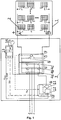
Fig.1 - present schematically a PV panels system with a solar inverter circuit, -
Fig.2 - is an electrical scheme of basic DC link circuit with ESR (Equivalent Series Resistance) embedded in the inverter circuit, -
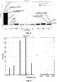
Fig. 3 - presents a fingerprints measurement on a diagram of a FFT of voltage UDC measurement, -
Fig.4 - presents a zoom diagram of a FFT of voltage UDC measurement, -
Fig. 5 - presents the FFT of voltage UDC fingerprints measurements to be stored, -
Fig.6 - presents the flowchart of the inventive method. - A
PV panels system 1, which containsPV Panels 2 with single panels p11 .. p1n; p21.. p2n; ....pn1..pnn (where n is a natural number) of the possible known kinds, connected in possible known ways (e.g. series or parallel). ThePV panels system 1 is connected through their outputs A and B with asolar inverter circuit 3 having aninverter unit 4 connected parallel with aDC link unit 5. Theinverter circuit 3 comprises a solarinverter control unit 6 connected electrically with a PVpanels monitoring unit 7. The solarinverter control unit 6 and the PVpanels monitoring unit 7 may be combined in single unit what is not presented in the drawing. Theinverter unit 4 has at least two solid state switches, forming an inverter switching leg for each phase a, b, c, for converting DC input voltage from thepanel system 1 into AC output voltage. The solid state switches of theinverter unit 4 are chosen from any of the possible known kinds - e.g. diodes, transistors, thyristors, etc. TheDC link unit 5 comprises at least oneDC link circuit 8 and a DC linkvoltage measuring device 9.DC link circuit 8 comprises capacitor C and an equivalent of series resistance ESR. Theinverter control unit 6 is a computer device, having adata acquisition module 10 for receiving and processing input signals from voltage signals UDC ofDC link unit 5, measured by thesensor 9 connected to thecircuit 8. Theinverter control unit 6 is also equipped with anoutput module 11 for generating switching signals forsolid switches inverter unit 4. Theinverter control unit 6 is also equipped with analarm generating module 12 for gathered the data received from the PVpanels monitoring unit 7, e.g. capacitance C of the DC link, the value of ESR (Equivalent Series Resistance) and the voltage values of measured signals UDC and for generating alarm dependent on the value of the fault indicator Find. The PVpanels monitoring unit 7 is a computer device, havingprocessing unit 13 for receiving and processing input signals i.e. voltage UDC ofDC link unit 5. The PVpanels monitoring unit 7 is equipped with afault indicator module 14 for calculating a fault indicator Find. Thefault indicator module 14 is connected with an indicationPV panels module 15.
The inventive method is implemented according to the following steps 1-6: - In the step S1 a voltage initial signal UDC1 of the
DC link circuit 8 is measured by the DC linkvoltage measuring device 9. In this step a user delivering constant values as a sensitivity indicator Senlnd (SenInd = i.e. 20%), a warning indicator Warlnd (Warlnd = i.e. 15%), an alarm indicator Alarlnd (Alarlnd = i.e. 30%) and a set number of frequencies SetF for further analysis (SetF = i.e. 1.....2000 Hz). The Optionally a set of numbers SetP of all panels p11,..........pnn is delivered by the user. - In the step S2 the voltage initial signal UDC1 is processed in order to obtain a fingerprints F1....Fn of the measured signal. This is done by performing a spectral analysis of the signal UDC1 by using a FFT (Fast Fourier Transform) process and from the characteristic frequencies of FFT(UDC1) signal amplitudes SigAMPfin(UDC1) of each fingerprint what is calculated in the known way, using the PV
panels monitoring unit 7. The fingerprints with signals amplitudes for the set of frequencies SetF given by the user is stored in thefault indication module 14.
Exemplary embodiment of the finger measurement is presented infig. 5 and in a table 1.Table 1. FREQUENCY (Hz) 1 2 3 4 5 ... 1998 1999 2000 FFT Amplitude (p.u.) 3 4 15 20 5 ... 0.1 0.3 0.1 - In the step S3 a consecutive voltage signal UDC2 of the
DC link circuit 8 is measured by the DC linkvoltage measuring device 9. For (n) measurements the consecutive voltage signal is indicated as UDCn, wherein for the previously measured signal (n-1) the indication is presented as UDCn-1. - In the step S4 the consecutive voltage signal UDC2 is processed in order to obtain fingerprints F11.....Fnn of the measured signal. This is done by performing a spectral analysis of the signal UDC2 by using a FFT (Fast Fourier Transform) process and from the characteristic frequencies of FFT(UDC2) signal amplitudes SigAMPfin(UDC2) of each fingerprint what is calculated in the known way, using the PV
panels monitoring unit 7. The fingerprints with signals amplitudes for the set of frequencies SetF given by the user is stored in thefault indication module 14.
The PVpanels monitoring unit 7 stores the amplitudes values of a chosen SetF set of frequencies amplitudes, given by the user instep 1, i.e. frequency of thescope 1..2000 Hz, concerning the value of a FFT amplitudes of the UDC2 of the fingerprints F11.....Fnn including signal consecutive amplitudes SigAMPcon(UDC2) of characteristic frequencies of FFT(UDC2). - In step 5 a process of a settlement of the fault indicator Find is performed by comparing the values of signal consecutive amplitudes SigAMPcon(UDC2) with the value of the signal amplitudes SigAMPfin(UDC1) of the characteristic frequencies of Fast Fourier Transform FFT(UDC1) of the voltage UDC1 of
DC link unit 5 calculated in thestep 2 taking into account the data delivered in the step S1. The percentage difference between the values of signal consecutive amplitudes SigAMPcon(UDC2) and the value of the signal amplitudes SigAMPfin(UDC1) is the fault indicator Find for each pair of fingerprints F1, F11; F2, F22; .....Fn, Fnn.
In the exemplary embodiment the sensitive indicator Senlnd was established as 20% of frequency amplitudes, the warning indicator Warlnd is established as 15 % and the alarm indicator Alarlnd was established as 30 %. The indicator Find is automatically transmitted from the PVpanels monitoring unit 7 to theinverter control unit 6.
Depending on the constant data in the step S1 and the value of the fault indicator Find settlement in the step S5, theinverter control unit 6 may send the warn signal command or the stop command signal to theinverter unit 4 via theoutput module 11.
After the decision is made by the system additional analysis of amplitudes values in module is made in step S6. If there is no alarm in step S5 the procedure goes back to step S3.
IF Find == Warning THENOuput Module 11 = RUN
IF Find == Alarm THENOuput Module 11 = STOP
If the fault indicator Find does not differ form from the constant data in the range of the value given by the user then the steps S3 and S4 are repeated for next consecutive measurement of the DC voltage link UDCn. - In this optional step S6 a detailed analysis of amplitudes values of chosen set number of frequencies (SetF = i.e. 1..2000 Hz) amplitudes, given by the user in step S1 of FFT(UDC1) of the voltage UDC1 of
DC link unit 5 from step 2 (SigAMPfin) and amplitudes values of chosen set number of frequencies (SetF = i.e. 1..2000 Hz) amplitudes, given by the user in step S4 of FFT(UDC2) of the voltage UDC2 ofDC link unit 5 from step step 4 (SigAMPcon) is performed under the condition that the set of numbers SetP of all panels p11,..........pnn is delivered by the user in the step S1. Depending on which characteristic frequencies of the specific panel p11 .. p1n... pn1; p21...p2n; pn1......pnn have their amplitudes changed in amplitudes values as with Senlnd indicator percentage i.e 20% given by the user in Step 1 (either above or below the SigAMPfin value) for characteristic frequencies a chosen SetF set of frequencies amplitudes, given by the user instep 1, i.e. 1..2000 Hz frequencies of FFT(UDC1)& FFT(UDC2) of the voltage UDC1& UDC2 ofDC link unit 5, i.e. 15 Hz, 18 Hz, 22Hz, the respective panel is indicated as a panel with a problem (i.e. shading, structure failure etc.). Exemplary embodiment of the panel problem p21 is presented in a table 2.Table 2 Frequency (Hz) i.e. 15, 18, 22 Value change Senlnd = i.e. 20% Panel problem p21 - SigAMPcon(15,18,22) = SigAMPfin(15, 18,22) +/- 20% x SigAMPfin(15, 18,22).
If there are changes in amplitudes values as with Senlnd indicator percentage i.e 20% given by the user in Step 1 (either above or below the SigAMPfin value) for characteristic frequencies a chosen SetF set of frequencies amplitudes, given by the user instep 1, i.e. 1..2000 Hz frequencies of FFT(UDC1)& FFT(UDC2) of the voltage UDC1& UDC2 ofDC link unit 5, i.e. 220 Hz, 305 Hz, 445 Hz, the respective panel is indicated as a panel with a problem (i.e. shading, structure failure etc.). Exemplary embodiment of the panel problem p22 is presented in a table 3.Table 3 Frequency (Hz) i.e. 220, 305, 445 Value change SenInd = i.e. 20% Panel problem p22 - This indicates the problems (i.e. shading, structure failure etc.) with panel p22 SigAMPcon(220,305,445) = SigAMPfin(220,305,445) +/- 20% x SigAMPfin(220,305,445)
- The information on which panels (i.e. p21, p22) are having problem, is stored in the indication
PV panels module 15 in a table PanelNums for next usage in an upper level diagnostic system or by service personnel, what is not presented in the drawing.
Claims (5)
- A method of PV panels (2) diagnostic in a PV panels system (1) using a solar inverter (3) having a inverter unit (4) with solid state switches (4a, 4b, 4c), connected parallel with a DC link (5), wherein the solar inverter (3) is equipped with a solar inverter control unit (6) and a PV panels monitoring unit (7), and the both units (6) and (7) are a computer devices, the method having the step of measuring output voltage signals UDC coming out from out the PV panel system (1) and a step of processing measured signals Udc by using the FFT (Fast Fourier Transform) of spectrum analysis, characterized in that the method comprises the following steps:- delivering to the control inverter unit (6) constant values as a sensitivity indicator Senlnd, a warning indicator Warlnd, and an alarm indicator Alarlnd,- creating fingerprints (F1, F11; .....Fn-1, Fnn) for each pair of the two consecutive DC link voltage Udc measurement Udc(n-1) and Udcn for each output voltage signals from the panel system (1),- comparing the amplitudes of at least one pair of fingerprints (F1, F11;......Fn-1, Fnn) of the measured voltage signals with a value from the set of frequencies chosen by the user and determining a fault indicator Find,- automatically triggering a command for the control unit (6) to warn or alarm stop for the inverter unit (4).
- A method according to claim 1, characterized in that the fingerprints (F1, F11; .....Fn-1, Fnn) are created for the characteristic frequencies of the range 1Hz to 2000Hz.
- A method according to claim 1, characterized in that the sensitivity indicator Senlnd has a value equal 20% of the value of the one pair of the fingerprints, the warning indicator Warlnd has a value 15% of the value of the one pair of the fingerprints, and an alarm indicator Alarlnd has a value 30% of the value of the one pair of the fingerprints.
- A method according to claim 1, characterized in that it further comprising the step of indicating failed PV panels by observing the changes in amplitudes of a single pair of the fingerprints (F1, F11; .....Fn-1, Fnn) prepared for each PV panel of a panel system (1), matching the measured value with an individual number of panel, which number is introduced by a user into the PV panel monitoring unit (7) and comparing the changes with a threshold given by the user.
- A method according to claim 4, characterized in that the changes in amplitudes of a single pair of the fingerprints (F1, F11; .....Fn-1, Fnn) are observed for the characteristic frequencies of the range 1Hz to 2000Hz.
Priority Applications (2)
| Application Number | Priority Date | Filing Date | Title |
|---|---|---|---|
| EP18460014.6A EP3537602B1 (en) | 2018-03-05 | 2018-03-05 | A method of pv panels diagnostic in pv panels system |
| ES18460014T ES2821133T3 (en) | 2018-03-05 | 2018-03-05 | Diagnostic method of photovoltaic panels in a photovoltaic panel system |
Applications Claiming Priority (1)
| Application Number | Priority Date | Filing Date | Title |
|---|---|---|---|
| EP18460014.6A EP3537602B1 (en) | 2018-03-05 | 2018-03-05 | A method of pv panels diagnostic in pv panels system |
Publications (2)
| Publication Number | Publication Date |
|---|---|
| EP3537602A1 true EP3537602A1 (en) | 2019-09-11 |
| EP3537602B1 EP3537602B1 (en) | 2020-08-05 |
Family
ID=61692204
Family Applications (1)
| Application Number | Title | Priority Date | Filing Date |
|---|---|---|---|
| EP18460014.6A Not-in-force EP3537602B1 (en) | 2018-03-05 | 2018-03-05 | A method of pv panels diagnostic in pv panels system |
Country Status (2)
| Country | Link |
|---|---|
| EP (1) | EP3537602B1 (en) |
| ES (1) | ES2821133T3 (en) |
Cited By (2)
| Publication number | Priority date | Publication date | Assignee | Title |
|---|---|---|---|---|
| CN112018886A (en) * | 2020-07-31 | 2020-12-01 | 国网山东省电力公司安丘市供电公司 | 400V photovoltaic grid-connected monitoring system |
| DE112020007864T5 (en) | 2020-12-22 | 2023-10-19 | Universidad Técnica Federico Santa María | System and method for determining the operating status of solar photovoltaic modules |
Citations (4)
| Publication number | Priority date | Publication date | Assignee | Title |
|---|---|---|---|---|
| EP1403649A2 (en) | 2002-09-30 | 2004-03-31 | Siemens Aktiengesellschaft | Procedure and device for diagnosing photovoltaic generators |
| WO2015165574A1 (en) | 2014-04-29 | 2015-11-05 | Abb Technology Ag | A method for monitoring dc link capacitance in a power converters |
| US20160282398A1 (en) * | 2015-03-25 | 2016-09-29 | Delta Electronics (Shanghai) Co., Ltd | Method and Device for ARC Fault Detection for Photovoltaic Inverter and Photovoltaic Inverter Using the Same |
| EP3121610A1 (en) * | 2015-07-23 | 2017-01-25 | Analog Devices Global | Computationally efficient arc detector with coherent sampling |
-
2018
- 2018-03-05 EP EP18460014.6A patent/EP3537602B1/en not_active Not-in-force
- 2018-03-05 ES ES18460014T patent/ES2821133T3/en active Active
Patent Citations (4)
| Publication number | Priority date | Publication date | Assignee | Title |
|---|---|---|---|---|
| EP1403649A2 (en) | 2002-09-30 | 2004-03-31 | Siemens Aktiengesellschaft | Procedure and device for diagnosing photovoltaic generators |
| WO2015165574A1 (en) | 2014-04-29 | 2015-11-05 | Abb Technology Ag | A method for monitoring dc link capacitance in a power converters |
| US20160282398A1 (en) * | 2015-03-25 | 2016-09-29 | Delta Electronics (Shanghai) Co., Ltd | Method and Device for ARC Fault Detection for Photovoltaic Inverter and Photovoltaic Inverter Using the Same |
| EP3121610A1 (en) * | 2015-07-23 | 2017-01-25 | Analog Devices Global | Computationally efficient arc detector with coherent sampling |
Non-Patent Citations (1)
| Title |
|---|
| ZHENG HONG ET AL: "Fault diagnosis of photovoltaic inverters using hidden Markov model", 2017 36TH CHINESE CONTROL CONFERENCE (CCC), TECHNICAL COMMITTEE ON CONTROL THEORY, CAA, 26 July 2017 (2017-07-26), pages 7290 - 7295, XP033149889, DOI: 10.23919/CHICC.2017.8028508 * |
Cited By (2)
| Publication number | Priority date | Publication date | Assignee | Title |
|---|---|---|---|---|
| CN112018886A (en) * | 2020-07-31 | 2020-12-01 | 国网山东省电力公司安丘市供电公司 | 400V photovoltaic grid-connected monitoring system |
| DE112020007864T5 (en) | 2020-12-22 | 2023-10-19 | Universidad Técnica Federico Santa María | System and method for determining the operating status of solar photovoltaic modules |
Also Published As
| Publication number | Publication date |
|---|---|
| ES2821133T3 (en) | 2021-04-23 |
| EP3537602B1 (en) | 2020-08-05 |
Similar Documents
| Publication | Publication Date | Title |
|---|---|---|
| EP2733805B1 (en) | Systems and methods of discriminating DC arcs and load switching noise | |
| US10615743B2 (en) | Active and passive monitoring system for installed photovoltaic strings, substrings, and modules | |
| EP2741388B1 (en) | Method and apparatus for detection and control of DC arc faults | |
| US10505370B2 (en) | Safety detection device and method of grid-connected inverter | |
| EP2887078A1 (en) | Method and apparatus for ground fault detection | |
| US9541598B2 (en) | Smart junction box for photovoltaic systems | |
| JP2014134445A (en) | Arc detector | |
| US9547033B1 (en) | Hierarchical fault prediction, detection and localization in PV systems with distributed electronics | |
| US20140142874A1 (en) | Home run arc detection at the photovoltaic string level using multiple current sensors | |
| KR101778772B1 (en) | The System and Method of Detecting Events by Checking Frequency in Microgrid | |
| US11404999B2 (en) | Method for detecting a contact fault in a photovoltaic system | |
| Fatama et al. | A multi feature based islanding classification technique for distributed generation systems | |
| EP2750258B1 (en) | Methods for locating ground faults and insulation degradation condition in energy conversion systems | |
| WO2015172959A1 (en) | Centralized dc curtailment for overvoltage protection | |
| JP2016131470A (en) | Abnormality detection system for photovoltaic power generation facilities | |
| EP3537602B1 (en) | A method of pv panels diagnostic in pv panels system | |
| EP3138191A1 (en) | A method for monitoring dc link capacitance in a power converters | |
| KR101509536B1 (en) | Monitoring system for solar light generation | |
| WO2021116399A1 (en) | A method and a system for series arc detection in a power circuit | |
| CN110073566A (en) | For detecting the method and its DC/AC converter apparatus of the isolated island situation of DC/AC converter apparatus | |
| KR102186867B1 (en) | Diagnosis apparatus and method of photovoltaic inverter using analysis of power quality | |
| US20200162023A1 (en) | Active and passive monitoring system for installed photovoltaic strings, substrings, and modules | |
| CN107589324B (en) | Online testing system for grid-connected inverter and capacitor | |
| Joga et al. | Tunable Q-wavelet transform based entropy measurement to detect and classify faults in certs microgrid test bed | |
| EP2779340B1 (en) | Home run arc detection at the photovoltaic string level using multiple current sensors |
Legal Events
| Date | Code | Title | Description |
|---|---|---|---|
| PUAI | Public reference made under article 153(3) epc to a published international application that has entered the european phase |
Free format text: ORIGINAL CODE: 0009012 |
|
| STAA | Information on the status of an ep patent application or granted ep patent |
Free format text: STATUS: THE APPLICATION HAS BEEN PUBLISHED |
|
| AK | Designated contracting states |
Kind code of ref document: A1 Designated state(s): AL AT BE BG CH CY CZ DE DK EE ES FI FR GB GR HR HU IE IS IT LI LT LU LV MC MK MT NL NO PL PT RO RS SE SI SK SM TR |
|
| AX | Request for extension of the european patent |
Extension state: BA ME |
|
| STAA | Information on the status of an ep patent application or granted ep patent |
Free format text: STATUS: REQUEST FOR EXAMINATION WAS MADE |
|
| 17P | Request for examination filed |
Effective date: 20191112 |
|
| RBV | Designated contracting states (corrected) |
Designated state(s): AL AT BE BG CH CY CZ DE DK EE ES FI FR GB GR HR HU IE IS IT LI LT LU LV MC MK MT NL NO PL PT RO RS SE SI SK SM TR |
|
| GRAP | Despatch of communication of intention to grant a patent |
Free format text: ORIGINAL CODE: EPIDOSNIGR1 |
|
| STAA | Information on the status of an ep patent application or granted ep patent |
Free format text: STATUS: GRANT OF PATENT IS INTENDED |
|
| INTG | Intention to grant announced |
Effective date: 20200207 |
|
| GRAS | Grant fee paid |
Free format text: ORIGINAL CODE: EPIDOSNIGR3 |
|
| RAP1 | Party data changed (applicant data changed or rights of an application transferred) |
Owner name: ABB SCHWEIZ AG |
|
| GRAA | (expected) grant |
Free format text: ORIGINAL CODE: 0009210 |
|
| STAA | Information on the status of an ep patent application or granted ep patent |
Free format text: STATUS: THE PATENT HAS BEEN GRANTED |
|
| AK | Designated contracting states |
Kind code of ref document: B1 Designated state(s): AL AT BE BG CH CY CZ DE DK EE ES FI FR GB GR HR HU IE IS IT LI LT LU LV MC MK MT NL NO PL PT RO RS SE SI SK SM TR |
|
| REG | Reference to a national code |
Ref country code: GB Ref legal event code: FG4D |
|
| REG | Reference to a national code |
Ref country code: CH Ref legal event code: EP |
|
| REG | Reference to a national code |
Ref country code: AT Ref legal event code: REF Ref document number: 1300145 Country of ref document: AT Kind code of ref document: T Effective date: 20200815 |
|
| REG | Reference to a national code |
Ref country code: DE Ref legal event code: R096 Ref document number: 602018006700 Country of ref document: DE |
|
| REG | Reference to a national code |
Ref country code: IE Ref legal event code: FG4D |
|
| RAP2 | Party data changed (patent owner data changed or rights of a patent transferred) |
Owner name: MARICI HOLDINGS THE NETHERLANDS B.V. |
|
| REG | Reference to a national code |
Ref country code: LT Ref legal event code: MG4D |
|
| REG | Reference to a national code |
Ref country code: NL Ref legal event code: MP Effective date: 20200805 |
|
| REG | Reference to a national code |
Ref country code: AT Ref legal event code: MK05 Ref document number: 1300145 Country of ref document: AT Kind code of ref document: T Effective date: 20200805 |
|
| PG25 | Lapsed in a contracting state [announced via postgrant information from national office to epo] |
Ref country code: LT Free format text: LAPSE BECAUSE OF FAILURE TO SUBMIT A TRANSLATION OF THE DESCRIPTION OR TO PAY THE FEE WITHIN THE PRESCRIBED TIME-LIMIT Effective date: 20200805 Ref country code: FI Free format text: LAPSE BECAUSE OF FAILURE TO SUBMIT A TRANSLATION OF THE DESCRIPTION OR TO PAY THE FEE WITHIN THE PRESCRIBED TIME-LIMIT Effective date: 20200805 Ref country code: HR Free format text: LAPSE BECAUSE OF FAILURE TO SUBMIT A TRANSLATION OF THE DESCRIPTION OR TO PAY THE FEE WITHIN THE PRESCRIBED TIME-LIMIT Effective date: 20200805 Ref country code: SE Free format text: LAPSE BECAUSE OF FAILURE TO SUBMIT A TRANSLATION OF THE DESCRIPTION OR TO PAY THE FEE WITHIN THE PRESCRIBED TIME-LIMIT Effective date: 20200805 Ref country code: PT Free format text: LAPSE BECAUSE OF FAILURE TO SUBMIT A TRANSLATION OF THE DESCRIPTION OR TO PAY THE FEE WITHIN THE PRESCRIBED TIME-LIMIT Effective date: 20201207 Ref country code: NO Free format text: LAPSE BECAUSE OF FAILURE TO SUBMIT A TRANSLATION OF THE DESCRIPTION OR TO PAY THE FEE WITHIN THE PRESCRIBED TIME-LIMIT Effective date: 20201105 Ref country code: GR Free format text: LAPSE BECAUSE OF FAILURE TO SUBMIT A TRANSLATION OF THE DESCRIPTION OR TO PAY THE FEE WITHIN THE PRESCRIBED TIME-LIMIT Effective date: 20201106 Ref country code: BG Free format text: LAPSE BECAUSE OF FAILURE TO SUBMIT A TRANSLATION OF THE DESCRIPTION OR TO PAY THE FEE WITHIN THE PRESCRIBED TIME-LIMIT Effective date: 20201105 Ref country code: AT Free format text: LAPSE BECAUSE OF FAILURE TO SUBMIT A TRANSLATION OF THE DESCRIPTION OR TO PAY THE FEE WITHIN THE PRESCRIBED TIME-LIMIT Effective date: 20200805 |
|
| PG25 | Lapsed in a contracting state [announced via postgrant information from national office to epo] |
Ref country code: RS Free format text: LAPSE BECAUSE OF FAILURE TO SUBMIT A TRANSLATION OF THE DESCRIPTION OR TO PAY THE FEE WITHIN THE PRESCRIBED TIME-LIMIT Effective date: 20200805 Ref country code: PL Free format text: LAPSE BECAUSE OF FAILURE TO SUBMIT A TRANSLATION OF THE DESCRIPTION OR TO PAY THE FEE WITHIN THE PRESCRIBED TIME-LIMIT Effective date: 20200805 Ref country code: NL Free format text: LAPSE BECAUSE OF FAILURE TO SUBMIT A TRANSLATION OF THE DESCRIPTION OR TO PAY THE FEE WITHIN THE PRESCRIBED TIME-LIMIT Effective date: 20200805 Ref country code: LV Free format text: LAPSE BECAUSE OF FAILURE TO SUBMIT A TRANSLATION OF THE DESCRIPTION OR TO PAY THE FEE WITHIN THE PRESCRIBED TIME-LIMIT Effective date: 20200805 Ref country code: IS Free format text: LAPSE BECAUSE OF FAILURE TO SUBMIT A TRANSLATION OF THE DESCRIPTION OR TO PAY THE FEE WITHIN THE PRESCRIBED TIME-LIMIT Effective date: 20201205 |
|
| REG | Reference to a national code |
Ref country code: ES Ref legal event code: FG2A Ref document number: 2821133 Country of ref document: ES Kind code of ref document: T3 Effective date: 20210423 |
|
| PG25 | Lapsed in a contracting state [announced via postgrant information from national office to epo] |
Ref country code: EE Free format text: LAPSE BECAUSE OF FAILURE TO SUBMIT A TRANSLATION OF THE DESCRIPTION OR TO PAY THE FEE WITHIN THE PRESCRIBED TIME-LIMIT Effective date: 20200805 Ref country code: RO Free format text: LAPSE BECAUSE OF FAILURE TO SUBMIT A TRANSLATION OF THE DESCRIPTION OR TO PAY THE FEE WITHIN THE PRESCRIBED TIME-LIMIT Effective date: 20200805 Ref country code: DK Free format text: LAPSE BECAUSE OF FAILURE TO SUBMIT A TRANSLATION OF THE DESCRIPTION OR TO PAY THE FEE WITHIN THE PRESCRIBED TIME-LIMIT Effective date: 20200805 Ref country code: CZ Free format text: LAPSE BECAUSE OF FAILURE TO SUBMIT A TRANSLATION OF THE DESCRIPTION OR TO PAY THE FEE WITHIN THE PRESCRIBED TIME-LIMIT Effective date: 20200805 Ref country code: SM Free format text: LAPSE BECAUSE OF FAILURE TO SUBMIT A TRANSLATION OF THE DESCRIPTION OR TO PAY THE FEE WITHIN THE PRESCRIBED TIME-LIMIT Effective date: 20200805 |
|
| REG | Reference to a national code |
Ref country code: DE Ref legal event code: R097 Ref document number: 602018006700 Country of ref document: DE |
|
| PG25 | Lapsed in a contracting state [announced via postgrant information from national office to epo] |
Ref country code: AL Free format text: LAPSE BECAUSE OF FAILURE TO SUBMIT A TRANSLATION OF THE DESCRIPTION OR TO PAY THE FEE WITHIN THE PRESCRIBED TIME-LIMIT Effective date: 20200805 |
|
| PLBE | No opposition filed within time limit |
Free format text: ORIGINAL CODE: 0009261 |
|
| STAA | Information on the status of an ep patent application or granted ep patent |
Free format text: STATUS: NO OPPOSITION FILED WITHIN TIME LIMIT |
|
| PG25 | Lapsed in a contracting state [announced via postgrant information from national office to epo] |
Ref country code: SK Free format text: LAPSE BECAUSE OF FAILURE TO SUBMIT A TRANSLATION OF THE DESCRIPTION OR TO PAY THE FEE WITHIN THE PRESCRIBED TIME-LIMIT Effective date: 20200805 |
|
| 26N | No opposition filed |
Effective date: 20210507 |
|
| PG25 | Lapsed in a contracting state [announced via postgrant information from national office to epo] |
Ref country code: SI Free format text: LAPSE BECAUSE OF FAILURE TO SUBMIT A TRANSLATION OF THE DESCRIPTION OR TO PAY THE FEE WITHIN THE PRESCRIBED TIME-LIMIT Effective date: 20200805 |
|
| PG25 | Lapsed in a contracting state [announced via postgrant information from national office to epo] |
Ref country code: MC Free format text: LAPSE BECAUSE OF FAILURE TO SUBMIT A TRANSLATION OF THE DESCRIPTION OR TO PAY THE FEE WITHIN THE PRESCRIBED TIME-LIMIT Effective date: 20200805 |
|
| REG | Reference to a national code |
Ref country code: CH Ref legal event code: PL |
|
| REG | Reference to a national code |
Ref country code: BE Ref legal event code: MM Effective date: 20210331 |
|
| PG25 | Lapsed in a contracting state [announced via postgrant information from national office to epo] |
Ref country code: IE Free format text: LAPSE BECAUSE OF NON-PAYMENT OF DUE FEES Effective date: 20210305 Ref country code: CH Free format text: LAPSE BECAUSE OF NON-PAYMENT OF DUE FEES Effective date: 20210331 Ref country code: FR Free format text: LAPSE BECAUSE OF NON-PAYMENT OF DUE FEES Effective date: 20210331 Ref country code: LI Free format text: LAPSE BECAUSE OF NON-PAYMENT OF DUE FEES Effective date: 20210331 Ref country code: LU Free format text: LAPSE BECAUSE OF NON-PAYMENT OF DUE FEES Effective date: 20210305 |
|
| PG25 | Lapsed in a contracting state [announced via postgrant information from national office to epo] |
Ref country code: BE Free format text: LAPSE BECAUSE OF NON-PAYMENT OF DUE FEES Effective date: 20210331 |
|
| GBPC | Gb: european patent ceased through non-payment of renewal fee |
Effective date: 20220305 |
|
| PG25 | Lapsed in a contracting state [announced via postgrant information from national office to epo] |
Ref country code: GB Free format text: LAPSE BECAUSE OF NON-PAYMENT OF DUE FEES Effective date: 20220305 |
|
| PGFP | Annual fee paid to national office [announced via postgrant information from national office to epo] |
Ref country code: IT Payment date: 20230328 Year of fee payment: 6 Ref country code: DE Payment date: 20230321 Year of fee payment: 6 |
|
| PG25 | Lapsed in a contracting state [announced via postgrant information from national office to epo] |
Ref country code: CY Free format text: LAPSE BECAUSE OF FAILURE TO SUBMIT A TRANSLATION OF THE DESCRIPTION OR TO PAY THE FEE WITHIN THE PRESCRIBED TIME-LIMIT Effective date: 20200805 |
|
| PG25 | Lapsed in a contracting state [announced via postgrant information from national office to epo] |
Ref country code: HU Free format text: LAPSE BECAUSE OF FAILURE TO SUBMIT A TRANSLATION OF THE DESCRIPTION OR TO PAY THE FEE WITHIN THE PRESCRIBED TIME-LIMIT; INVALID AB INITIO Effective date: 20180305 |
|
| PGFP | Annual fee paid to national office [announced via postgrant information from national office to epo] |
Ref country code: ES Payment date: 20230529 Year of fee payment: 6 |
|
| PG25 | Lapsed in a contracting state [announced via postgrant information from national office to epo] |
Ref country code: MK Free format text: LAPSE BECAUSE OF FAILURE TO SUBMIT A TRANSLATION OF THE DESCRIPTION OR TO PAY THE FEE WITHIN THE PRESCRIBED TIME-LIMIT Effective date: 20200805 |
|
| PG25 | Lapsed in a contracting state [announced via postgrant information from national office to epo] |
Ref country code: MT Free format text: LAPSE BECAUSE OF FAILURE TO SUBMIT A TRANSLATION OF THE DESCRIPTION OR TO PAY THE FEE WITHIN THE PRESCRIBED TIME-LIMIT Effective date: 20200805 |
|
| REG | Reference to a national code |
Ref country code: DE Ref legal event code: R119 Ref document number: 602018006700 Country of ref document: DE |
|
| PG25 | Lapsed in a contracting state [announced via postgrant information from national office to epo] |
Ref country code: DE Free format text: LAPSE BECAUSE OF NON-PAYMENT OF DUE FEES Effective date: 20241001 |
|
| PG25 | Lapsed in a contracting state [announced via postgrant information from national office to epo] |
Ref country code: DE Free format text: LAPSE BECAUSE OF NON-PAYMENT OF DUE FEES Effective date: 20241001 |
|
| REG | Reference to a national code |
Ref country code: ES Ref legal event code: FD2A Effective date: 20250425 |
|
| PG25 | Lapsed in a contracting state [announced via postgrant information from national office to epo] |
Ref country code: IT Free format text: LAPSE BECAUSE OF NON-PAYMENT OF DUE FEES Effective date: 20240305 |
|
| PG25 | Lapsed in a contracting state [announced via postgrant information from national office to epo] |
Ref country code: ES Free format text: LAPSE BECAUSE OF NON-PAYMENT OF DUE FEES Effective date: 20240306 |
|
| PG25 | Lapsed in a contracting state [announced via postgrant information from national office to epo] |
Ref country code: TR Free format text: LAPSE BECAUSE OF FAILURE TO SUBMIT A TRANSLATION OF THE DESCRIPTION OR TO PAY THE FEE WITHIN THE PRESCRIBED TIME-LIMIT Effective date: 20200805 |