EP3537431A1 - Active noise cancellation system utilizing a diagonalization filter matrix - Google Patents
Active noise cancellation system utilizing a diagonalization filter matrix Download PDFInfo
- Publication number
- EP3537431A1 EP3537431A1 EP19160668.0A EP19160668A EP3537431A1 EP 3537431 A1 EP3537431 A1 EP 3537431A1 EP 19160668 A EP19160668 A EP 19160668A EP 3537431 A1 EP3537431 A1 EP 3537431A1
- Authority
- EP
- European Patent Office
- Prior art keywords
- signals
- error
- estimated
- frequency domain
- noise
- Prior art date
- Legal status (The legal status is an assumption and is not a legal conclusion. Google has not performed a legal analysis and makes no representation as to the accuracy of the status listed.)
- Granted
Links
Images

Classifications
-
- H—ELECTRICITY
- H04—ELECTRIC COMMUNICATION TECHNIQUE
- H04R—LOUDSPEAKERS, MICROPHONES, GRAMOPHONE PICK-UPS OR LIKE ACOUSTIC ELECTROMECHANICAL TRANSDUCERS; ELECTRIC HEARING AIDS; PUBLIC ADDRESS SYSTEMS
- H04R3/00—Circuits for transducers
- H04R3/002—Damping circuit arrangements for transducers, e.g. motional feedback circuits
-
- G—PHYSICS
- G10—MUSICAL INSTRUMENTS; ACOUSTICS
- G10K—SOUND-PRODUCING DEVICES; METHODS OR DEVICES FOR PROTECTING AGAINST, OR FOR DAMPING, NOISE OR OTHER ACOUSTIC WAVES IN GENERAL; ACOUSTICS NOT OTHERWISE PROVIDED FOR
- G10K11/00—Methods or devices for transmitting, conducting or directing sound in general; Methods or devices for protecting against, or for damping, noise or other acoustic waves in general
- G10K11/16—Methods or devices for protecting against, or for damping, noise or other acoustic waves in general
- G10K11/175—Methods or devices for protecting against, or for damping, noise or other acoustic waves in general using interference effects; Masking sound
- G10K11/178—Methods or devices for protecting against, or for damping, noise or other acoustic waves in general using interference effects; Masking sound by electro-acoustically regenerating the original acoustic waves in anti-phase
- G10K11/1781—Methods or devices for protecting against, or for damping, noise or other acoustic waves in general using interference effects; Masking sound by electro-acoustically regenerating the original acoustic waves in anti-phase characterised by the analysis of input or output signals, e.g. frequency range, modes, transfer functions
- G10K11/17813—Methods or devices for protecting against, or for damping, noise or other acoustic waves in general using interference effects; Masking sound by electro-acoustically regenerating the original acoustic waves in anti-phase characterised by the analysis of input or output signals, e.g. frequency range, modes, transfer functions characterised by the analysis of the acoustic paths, e.g. estimating, calibrating or testing of transfer functions or cross-terms
- G10K11/17815—Methods or devices for protecting against, or for damping, noise or other acoustic waves in general using interference effects; Masking sound by electro-acoustically regenerating the original acoustic waves in anti-phase characterised by the analysis of input or output signals, e.g. frequency range, modes, transfer functions characterised by the analysis of the acoustic paths, e.g. estimating, calibrating or testing of transfer functions or cross-terms between the reference signals and the error signals, i.e. primary path
-
- G—PHYSICS
- G10—MUSICAL INSTRUMENTS; ACOUSTICS
- G10K—SOUND-PRODUCING DEVICES; METHODS OR DEVICES FOR PROTECTING AGAINST, OR FOR DAMPING, NOISE OR OTHER ACOUSTIC WAVES IN GENERAL; ACOUSTICS NOT OTHERWISE PROVIDED FOR
- G10K11/00—Methods or devices for transmitting, conducting or directing sound in general; Methods or devices for protecting against, or for damping, noise or other acoustic waves in general
- G10K11/16—Methods or devices for protecting against, or for damping, noise or other acoustic waves in general
- G10K11/175—Methods or devices for protecting against, or for damping, noise or other acoustic waves in general using interference effects; Masking sound
- G10K11/178—Methods or devices for protecting against, or for damping, noise or other acoustic waves in general using interference effects; Masking sound by electro-acoustically regenerating the original acoustic waves in anti-phase
-
- G—PHYSICS
- G10—MUSICAL INSTRUMENTS; ACOUSTICS
- G10K—SOUND-PRODUCING DEVICES; METHODS OR DEVICES FOR PROTECTING AGAINST, OR FOR DAMPING, NOISE OR OTHER ACOUSTIC WAVES IN GENERAL; ACOUSTICS NOT OTHERWISE PROVIDED FOR
- G10K11/00—Methods or devices for transmitting, conducting or directing sound in general; Methods or devices for protecting against, or for damping, noise or other acoustic waves in general
- G10K11/16—Methods or devices for protecting against, or for damping, noise or other acoustic waves in general
- G10K11/175—Methods or devices for protecting against, or for damping, noise or other acoustic waves in general using interference effects; Masking sound
- G10K11/178—Methods or devices for protecting against, or for damping, noise or other acoustic waves in general using interference effects; Masking sound by electro-acoustically regenerating the original acoustic waves in anti-phase
- G10K11/1781—Methods or devices for protecting against, or for damping, noise or other acoustic waves in general using interference effects; Masking sound by electro-acoustically regenerating the original acoustic waves in anti-phase characterised by the analysis of input or output signals, e.g. frequency range, modes, transfer functions
- G10K11/17821—Methods or devices for protecting against, or for damping, noise or other acoustic waves in general using interference effects; Masking sound by electro-acoustically regenerating the original acoustic waves in anti-phase characterised by the analysis of input or output signals, e.g. frequency range, modes, transfer functions characterised by the analysis of the input signals only
- G10K11/17823—Reference signals, e.g. ambient acoustic environment
-
- G—PHYSICS
- G10—MUSICAL INSTRUMENTS; ACOUSTICS
- G10K—SOUND-PRODUCING DEVICES; METHODS OR DEVICES FOR PROTECTING AGAINST, OR FOR DAMPING, NOISE OR OTHER ACOUSTIC WAVES IN GENERAL; ACOUSTICS NOT OTHERWISE PROVIDED FOR
- G10K11/00—Methods or devices for transmitting, conducting or directing sound in general; Methods or devices for protecting against, or for damping, noise or other acoustic waves in general
- G10K11/16—Methods or devices for protecting against, or for damping, noise or other acoustic waves in general
- G10K11/175—Methods or devices for protecting against, or for damping, noise or other acoustic waves in general using interference effects; Masking sound
- G10K11/178—Methods or devices for protecting against, or for damping, noise or other acoustic waves in general using interference effects; Masking sound by electro-acoustically regenerating the original acoustic waves in anti-phase
- G10K11/1781—Methods or devices for protecting against, or for damping, noise or other acoustic waves in general using interference effects; Masking sound by electro-acoustically regenerating the original acoustic waves in anti-phase characterised by the analysis of input or output signals, e.g. frequency range, modes, transfer functions
- G10K11/17821—Methods or devices for protecting against, or for damping, noise or other acoustic waves in general using interference effects; Masking sound by electro-acoustically regenerating the original acoustic waves in anti-phase characterised by the analysis of input or output signals, e.g. frequency range, modes, transfer functions characterised by the analysis of the input signals only
- G10K11/17825—Error signals
-
- G—PHYSICS
- G10—MUSICAL INSTRUMENTS; ACOUSTICS
- G10K—SOUND-PRODUCING DEVICES; METHODS OR DEVICES FOR PROTECTING AGAINST, OR FOR DAMPING, NOISE OR OTHER ACOUSTIC WAVES IN GENERAL; ACOUSTICS NOT OTHERWISE PROVIDED FOR
- G10K11/00—Methods or devices for transmitting, conducting or directing sound in general; Methods or devices for protecting against, or for damping, noise or other acoustic waves in general
- G10K11/16—Methods or devices for protecting against, or for damping, noise or other acoustic waves in general
- G10K11/175—Methods or devices for protecting against, or for damping, noise or other acoustic waves in general using interference effects; Masking sound
- G10K11/178—Methods or devices for protecting against, or for damping, noise or other acoustic waves in general using interference effects; Masking sound by electro-acoustically regenerating the original acoustic waves in anti-phase
- G10K11/1785—Methods, e.g. algorithms; Devices
- G10K11/17853—Methods, e.g. algorithms; Devices of the filter
- G10K11/17854—Methods, e.g. algorithms; Devices of the filter the filter being an adaptive filter
-
- G—PHYSICS
- G10—MUSICAL INSTRUMENTS; ACOUSTICS
- G10K—SOUND-PRODUCING DEVICES; METHODS OR DEVICES FOR PROTECTING AGAINST, OR FOR DAMPING, NOISE OR OTHER ACOUSTIC WAVES IN GENERAL; ACOUSTICS NOT OTHERWISE PROVIDED FOR
- G10K11/00—Methods or devices for transmitting, conducting or directing sound in general; Methods or devices for protecting against, or for damping, noise or other acoustic waves in general
- G10K11/16—Methods or devices for protecting against, or for damping, noise or other acoustic waves in general
- G10K11/175—Methods or devices for protecting against, or for damping, noise or other acoustic waves in general using interference effects; Masking sound
- G10K11/178—Methods or devices for protecting against, or for damping, noise or other acoustic waves in general using interference effects; Masking sound by electro-acoustically regenerating the original acoustic waves in anti-phase
- G10K11/1787—General system configurations
- G10K11/17879—General system configurations using both a reference signal and an error signal
-
- G—PHYSICS
- G10—MUSICAL INSTRUMENTS; ACOUSTICS
- G10K—SOUND-PRODUCING DEVICES; METHODS OR DEVICES FOR PROTECTING AGAINST, OR FOR DAMPING, NOISE OR OTHER ACOUSTIC WAVES IN GENERAL; ACOUSTICS NOT OTHERWISE PROVIDED FOR
- G10K11/00—Methods or devices for transmitting, conducting or directing sound in general; Methods or devices for protecting against, or for damping, noise or other acoustic waves in general
- G10K11/16—Methods or devices for protecting against, or for damping, noise or other acoustic waves in general
- G10K11/175—Methods or devices for protecting against, or for damping, noise or other acoustic waves in general using interference effects; Masking sound
- G10K11/178—Methods or devices for protecting against, or for damping, noise or other acoustic waves in general using interference effects; Masking sound by electro-acoustically regenerating the original acoustic waves in anti-phase
- G10K11/1787—General system configurations
- G10K11/17879—General system configurations using both a reference signal and an error signal
- G10K11/17881—General system configurations using both a reference signal and an error signal the reference signal being an acoustic signal, e.g. recorded with a microphone
-
- G—PHYSICS
- G10—MUSICAL INSTRUMENTS; ACOUSTICS
- G10K—SOUND-PRODUCING DEVICES; METHODS OR DEVICES FOR PROTECTING AGAINST, OR FOR DAMPING, NOISE OR OTHER ACOUSTIC WAVES IN GENERAL; ACOUSTICS NOT OTHERWISE PROVIDED FOR
- G10K2210/00—Details of active noise control [ANC] covered by G10K11/178 but not provided for in any of its subgroups
- G10K2210/10—Applications
- G10K2210/128—Vehicles
- G10K2210/1282—Automobiles
-
- G—PHYSICS
- G10—MUSICAL INSTRUMENTS; ACOUSTICS
- G10K—SOUND-PRODUCING DEVICES; METHODS OR DEVICES FOR PROTECTING AGAINST, OR FOR DAMPING, NOISE OR OTHER ACOUSTIC WAVES IN GENERAL; ACOUSTICS NOT OTHERWISE PROVIDED FOR
- G10K2210/00—Details of active noise control [ANC] covered by G10K11/178 but not provided for in any of its subgroups
- G10K2210/30—Means
- G10K2210/301—Computational
- G10K2210/3019—Cross-terms between multiple in's and out's
-
- G—PHYSICS
- G10—MUSICAL INSTRUMENTS; ACOUSTICS
- G10K—SOUND-PRODUCING DEVICES; METHODS OR DEVICES FOR PROTECTING AGAINST, OR FOR DAMPING, NOISE OR OTHER ACOUSTIC WAVES IN GENERAL; ACOUSTICS NOT OTHERWISE PROVIDED FOR
- G10K2210/00—Details of active noise control [ANC] covered by G10K11/178 but not provided for in any of its subgroups
- G10K2210/30—Means
- G10K2210/301—Computational
- G10K2210/3023—Estimation of noise, e.g. on error signals
- G10K2210/30232—Transfer functions, e.g. impulse response
-
- G—PHYSICS
- G10—MUSICAL INSTRUMENTS; ACOUSTICS
- G10K—SOUND-PRODUCING DEVICES; METHODS OR DEVICES FOR PROTECTING AGAINST, OR FOR DAMPING, NOISE OR OTHER ACOUSTIC WAVES IN GENERAL; ACOUSTICS NOT OTHERWISE PROVIDED FOR
- G10K2210/00—Details of active noise control [ANC] covered by G10K11/178 but not provided for in any of its subgroups
- G10K2210/30—Means
- G10K2210/301—Computational
- G10K2210/3026—Feedback
-
- G—PHYSICS
- G10—MUSICAL INSTRUMENTS; ACOUSTICS
- G10K—SOUND-PRODUCING DEVICES; METHODS OR DEVICES FOR PROTECTING AGAINST, OR FOR DAMPING, NOISE OR OTHER ACOUSTIC WAVES IN GENERAL; ACOUSTICS NOT OTHERWISE PROVIDED FOR
- G10K2210/00—Details of active noise control [ANC] covered by G10K11/178 but not provided for in any of its subgroups
- G10K2210/30—Means
- G10K2210/301—Computational
- G10K2210/3028—Filtering, e.g. Kalman filters or special analogue or digital filters
-
- G—PHYSICS
- G10—MUSICAL INSTRUMENTS; ACOUSTICS
- G10K—SOUND-PRODUCING DEVICES; METHODS OR DEVICES FOR PROTECTING AGAINST, OR FOR DAMPING, NOISE OR OTHER ACOUSTIC WAVES IN GENERAL; ACOUSTICS NOT OTHERWISE PROVIDED FOR
- G10K2210/00—Details of active noise control [ANC] covered by G10K11/178 but not provided for in any of its subgroups
- G10K2210/30—Means
- G10K2210/301—Computational
- G10K2210/3044—Phase shift, e.g. complex envelope processing
-
- G—PHYSICS
- G10—MUSICAL INSTRUMENTS; ACOUSTICS
- G10K—SOUND-PRODUCING DEVICES; METHODS OR DEVICES FOR PROTECTING AGAINST, OR FOR DAMPING, NOISE OR OTHER ACOUSTIC WAVES IN GENERAL; ACOUSTICS NOT OTHERWISE PROVIDED FOR
- G10K2210/00—Details of active noise control [ANC] covered by G10K11/178 but not provided for in any of its subgroups
- G10K2210/30—Means
- G10K2210/301—Computational
- G10K2210/3046—Multiple acoustic inputs, multiple acoustic outputs
Definitions
- aspects of the disclosure generally relate to active noise cancellation systems utilizing a diagonalization filter matrix.
- ANC Active noise cancellation
- Potential sources of undesired noise may come from undesired voices, heating, ventilation, and air conditioning systems and other environment noise in a room listening space. Potential sources may also come from vehicle engine, tire interaction with the road and other environment noise in a vehicle cabin listening space.
- ANC systems may use feedforward and feedback structures, to adaptively formulate anti-noise signals. Sensors placed near the potential sources provide the reference signals for the feedforward structure. Sensors placed near the listeners' ear positions provide the error signals for the feedback structure.
- the destructively-interfering anti-noise sound waves may be produced through loudspeakers to combine with the undesired sound waves in an attempt to cancel the undesired noise. Combination of the anti-noise sound waves and the undesired sound waves can eliminate or minimize perception of the undesired sound waves by one or more listeners within a listening space.
- Sound zones may be generated using speaker arrays and audio processing techniques providing acoustic isolation. Using such a system, different sound material may be delivered in different zones with limited interfering signals from adjacent sound zones. In order to realize the sound zones, a system may be designed using learning algorithm to adjust the response of multiple sound sources to approximate the desired sound field in the reproduction region.
- an active noise cancellation system uses a diagonalization matrix to process anti-noise signals.
- the system realizes sound zones, each including one or more microphones and one or more loudspeakers.
- the system includes a diagonalization matrix, which is designed offline, to realize the sound zones.
- the system further includes an audio processor programmed to generate anti-noise signals for each sound zone, based on the reference signals and feedback signals, through an adaptive filter system, using an estimated acoustic transfer function that provides an estimated effect on sound waves traversing the physical path.
- the adaptive filters are driven by a learning algorithm unit.
- the learning algorithm unit is based in part on the feedback error signals, the reference signals, and the filtered reference signals by the estimated acoustic transfer functions combined with the diagonalization matrix.
- the anti-noise signals include signals per sound zone.
- the system performs a sum across filtered references on the adaptive filter output signals, to generate a set of anti-noise signals per sound zone; processes the set of anti-noise signals using a diagonalization matrix to generate a set of output signals per loudspeaker; and drives the loudspeakers with the output signals per loudspeaker to apply the anti-noise signals to cancel the environmental noise in each zone.
- an active noise cancellation method using a diagonalization matrix, performs cancelling of environmental noise.
- Estimated output signals of the reference signals are generated using an estimated filter path transfer function that provides an estimated effect on sound waves traversing a physical path, the estimated filter path transfer function performing processing according to a diagonalization matrix and reference signals.
- Preliminary anti-noise signals are generated from the reference signals using an adaptive filter driven by learning unit signals received from a learning algorithm unit. The learning unit signals are based in part on error output signals generated from the estimated output signals.
- the anti-noise signals include signals per sound zone and per reference signal. Each sound zone includes a microphone and one or more loudspeakers.
- a sum across references is performed on the preliminary anti-noise signals to generate a set of output signals per sound zone.
- the set of output signals are processed by the diagonalization matrix to generate a set of output signals per loudspeaker.
- the loudspeakers are driven using the output signals per loudspeaker to apply the anti-noise signals to cancel the environmental noise.
- LMS Least Means Square
- FxLMS Filtered-x Least Means Square
- Traditional algorithms usually employ a large filter system, which is adaptive in operation. The performance of noise cancellation relies on the convergence of the entire filter system. Due to the complex acoustic environment and highly limited adaptation time, optimal convergence is usually difficult to achieve, which leads to unsatisfying performance.
- This disclosure combines an active noise cancellation (ANC) system with a diagonalization filter matrix.
- This combination simplifies cabin acoustic management by diagonalizing a speaker-to-microphone transfer function matrix of the ANC.
- the disclosure separates the noise cancellation effort into (i) offline acoustic tuning, i.e., designing of the diagonalization filter matrix, and (ii) real-time adaptation of the decoupled, simplified ANC filter system.
- offline acoustic tuning i.e., designing of the diagonalization filter matrix
- real-time adaptation of the decoupled, simplified ANC filter system real-time adaptation of the decoupled, simplified ANC filter system.
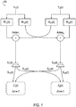
- FIG. 1 illustrates an example system 100 including two sound zones. Sound zones may be implemented in various settings, such as for different seating positions in a vehicle interior.
- the audio signals and transfer functions are frequency domain signals and functions, which have corresponding time domain signals and functions, respectively.
- the first sound zone input audio signal Y 1 ( z ) is intended for reproduction in the first sound zone Z 1 ( z ), while the second sound zone input audio signal Y 2 ( z ) is intended for reproduction in the second sound zone Z 2 ( z ).
- the illustrated sound zone system is a one-way system, without feedback. It should be noted that the illustration of two sound zones is provided as a minimal version for ease of explanation, and systems having a greater number of sound zones may be used.
- the input audio signals Y 1 ( z ) and Y 2 ( z ) are pre-filtered by inverse filters , , , and .
- the filter output signals are combined as illustrated in FIG. 1 .
- the first loudspeaker radiates the signal U 1 ( z ) as an acoustic signal that traverses through the physical paths S 11 ( z ) and S 12 ( z ) and arrives in the first sound zone and the second sound zone, respectively.
- the second loudspeaker radiates the signal U 2 ( z ) as an acoustic signal that traverses through the physical paths S 21 ( z ) and S 22 ( z ) and arrives in the first sound zone and the second sound zone, respectively.
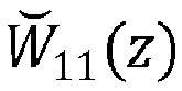
- the transfer function H 11 ( z ) denotes overall system transfer function in the frequency domain, i.e., the combination of the diagonalization filters , , , and and the room transfer functions S 11 ( z ), S 21 ( z ), S 12 ( z ) and S 22 ( z ).
- H 12 ( z ) and H 21 ( z ) are equal to 0.
- I z ⁇ z ⁇ N S z W ⁇ z
- I ( z ) is the 2x2 identity matrix
- designing a sound zone reproduction system is, from a mathematical point of view, an issue of inverting the transfer function matrix S(z), which represents the room impulse responses in the frequency domain, i.e., an issue of diagonalizing the overall system transfer function matrix by designing the diagonalization matrix .
- This computation can be performed offline, before the zone sound reproduction system is used.
- Various methods are known for matrix inversion.
- the expression adj ( S ( z )) represents the adjugate matrix of the square matrix S(z).
- the pre-filtering may be done in two stages, wherein the filter transfer function adj ( S ( z )) ensures a damping of the crosstalk and the filter transfer function det ( S ) -1 compensates for the linear distortions caused by transfer function adj ( S ( z )).
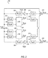
- FIG. 2 illustrates an example 200 half signal flow of a system for tuning the diagonalization filter matrices of FIG. 1 .
- the details shown in FIG. 2 correspond to the filtering performed for the processing of the input signal Y 1 ( z ).
- the illustrated system receives the input signal Y 1 ( z ), and processes the signal Y 1 ( z ) using the filter matrices and to generate the loudspeaker signals U 1 ( z ) and U 2 ( z ).
- U 1 ( z ) traverses through the physical paths S 11 ( z ) and S 12 ( z ) and arrives in the first sound zone and the second sound zone, respectively.
- U 2 ( z ) traverses through the physical paths S 21 ( z ) and S 22 ( z ) and arrives in the first sound zone and the second sound zone, respectively.
- the output of the microphone 215 is further compared to the input signal Y 1 ( z ) to generate the error signal E 1 ( z ), and the output of the microphone 216 is used to generate the error signal E 2 ( z ).
- the error signals E 1 ( z ) and E 2 ( z ) are minimized, respectively, such that Y 1 ( z ) is reproduced in the first sound zone, and minimized in the second sound zone.
- a similar signal flow may additionally be provided for the processing of the input signal Y 2 ( z ) according to the filter matrices and to have Y 2 ( z ) reproduced in the second sound zone, and minimized in the first sound zone.
- the input signal Y 1 ( z ) is supplied to four filters 201-204, which form a 2 x 2 matrix of modeled acoustic transfer functions ⁇ 11 ( z ), ⁇ 12 ( z ), ⁇ 21 ( z ) and ⁇ 22 ( z ), and to two filters 205 and 206, which form a filter matrix comprising and .
- Filters 205 and 206 are controlled by learning units 207 and 208, whereby the learning unit 207 receives signals from filters 201 and 202 and error signals E 1 ( z ) and E 2 ( z ), and the learning unit 208 receives signals from filter 203 and 204 and error signals E 1 ( z ) and E 2 ( z ).
- Filters 205 and 206 provide signals U 1 ( z ) and U 2 ( z ) for loudspeakers 209 and 210.
- the signal U 1 ( z ) is radiated by a first loudspeaker 209 via acoustic paths 211 and 212 to microphones 215 and 216, respectively.
- the signal U 2 ( z ) is radiated by a second loudspeaker 210 via acoustic paths 213 and 214 to the microphones 215 and 216, respectively.
- the microphones 215 and 216 respectively generate the error signals E 1 ( z ) and E 2 ( z ) based on the received signals and the desired signal Y 1 ( z ).
- the filters 201-204 with the transfer functions ⁇ 11 ( z ), ⁇ 12 ( z ), ⁇ 21 ( z ) and ⁇ 22 ( z ) model the various acoustic paths 211-214, which have respective transfer functions S 11 ( z ), S 12 ( z ), S 21 ( z ) and S 22 ( z ). It should be noted that while the illustrated example 200 includes one microphone per sound zone, other tuning systems may be implemented that utilize multiple microphones per sound zone to improve accuracy.
- FIG. 3 illustrates an example ANC system 300 and an example physical environment.
- an undesired noise source X ( z ) may traverse a physical path 304 to a microphone 306.
- the physical path 304 may be represented by a frequency domain transfer function P(z), which is unknown.
- the resultant undesired noise, due to traversal of the noise over the physical path 304, may be referred to as P ( z ) X ( z ).
- X ( z ) may be measured using a sensor and acquired through use of an analog-to-digital (A/D) converter.
- the undesired noise source X ( z ) may also be used as an input to an adaptive filter 308, which may be included in an anti-noise generator 309.
- the adaptive filter 308 may be represented by a frequency domain transfer function W ( z) .
- the adaptive filter 308 may be a digital filter configured to be dynamically adapted to filter an input to produce a desired anti-noise signal
- the anti-noise signal 310 and an audio signal 312 generated by an audio system 314 may be combined to drive a loudspeaker 316.
- the combination of the anti-noise signal 310 and the audio signal 312 may produce the sound wave output from the loudspeaker 316.
- the loudspeaker 316 is represented by a summation operation in FIG. 3 , having a speaker output 318.
- the speaker output 318 may be a sound wave that traverses through a physical path 320 that includes a path from the loudspeaker 316 to the microphone 306.
- the physical path 320 may be represented in FIG. 3 by a frequency domain transfer function S ( z ).
- the speaker output 318 and the undesired noise may be received by the microphone 306 and a microphone output signal 322 may be generated by the microphone 306. In other examples, any number of loudspeakers and microphones may be present.
- a component representative of the audio signal 312 may be removed from the microphone output signal 322, through processing of the microphone output signal 322.
- the audio signal 312 may be processed to reflect the traversal of the physical path 320 by the sound wave of the audio signal 312. This processing may be performed by estimating the physical path 320 as a modeled acoustic path filter 324, which provides an estimated effect on an audio signal sound wave traversing the physical path 320.
- the modeled acoustic path filter 324 is configured to simulate the effect on the sound wave of the audio signal 312 of traveling through the physical path 320 and generate an output signal 334.
- the modeled acoustic path filter 324 may be represented as a frequency domain transfer function ⁇ ( z ).
- the microphone output signal 322 may be processed such that a component representative of the audio output signal 334 is removed as indicated by a summation operation 326. This may occur by inverting the filtered audio signal at the summation operation 326 and adding the inverted signal to the microphone output signal 322. Alternatively, the filtered audio signal could be subtracted or any other mechanism or method to remove the signal could be used.
- the output of the summation operation 326 is an error signal 328, which may represent an audible signal remaining after any destructive interference between the anti-noise signal 310 projected through the loudspeaker 316 and the undesired noise sound originated from X ( z ).
- the summation operation 326 removing a component representative of the audio output signal 334 from the microphone output signal 322 may be considered as being included in the ANC system 300.
- the error signal 328 is transmitted to a real-time learning algorithm unit (LAU) 330, which may be included in the anti-noise generator 309.
- the LAU 330 may implement various learning algorithms, such as least mean squares (LMS), recursive least mean squares (RLMS), normalized least mean squares (NLMS), or any other suitable learning algorithm.
- LMS least mean squares
- RLMS recursive least mean squares
- NLMS normalized least mean squares
- the LAU 330 also receives as an input the undesired noise source X ( z ) filtered by the modeled acoustic path filter 324.
- a LAU output 332 may be an update signal transmitted to the adaptive filter 308.
- the adaptive filter 308 is configured to receive the undesired noise source X ( z ) and the LAU output 332.
- the LAU output 332 is transmitted to the adaptive filter 308 in order to more accurately cancel the undesired noise source X(z) by providing the
- ANC schemes such as described in FIG. 3 require a large amount of input channels of noise source reference and feedback microphone signals, as well as a large amount of output channels of speakers. Moreover, the performance of noise cancellation relies on the convergence of the entire filter system. Due to the complex cabin acoustic environment and highly limited adaptation time, optimal convergence is usually difficult to achieve, which leads to unsatisfying performance.
- performance of ANC systems such as that shown in FIG. 3 are sensitive to all microphone 306 inputs. Failure of one microphone 306 may cause performance degradation in the particular seat/zone associated with the failed microphone 306. It may also create performance variation in other seats/zones, as the system tries to adapt to the next possible optimal solution with less input information.
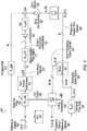
- FIG. 4 illustrates an example multichannel ANC system 400 using a diagonalization filter matrix 418 to perform ANC in terms of sound zones.
- L the number of loudspeakers
- M the number of microphones and seating zones
- R the number of reference signals ( e.g., channels of measured noise source)
- [ k ] be the k th sample in frequency domain
- [ n ] be the n th sample or n th frame in time domain.
- the multichannel ANC system 400 may operate in a manner similar to the ANC system 300 as described with regard to FIG. 3 , but using the sound zone concepts as described with regard to FIGS. 1-2 to reduce system processing requirements.
- the R reference signals 402 indicate sensed signals that is physically close to sources of noise, and that traverse a physical path 404. Because the reference signals 402 are close to the sources, they may offer a signal that is leading in time.
- the noises originated from the reference signals 402 along with sounds from the loudspeakers 422 are combined in the air 406 and received by M error microphones 408.
- the R reference signals 402 may also be input to an adaptive filter 410, which may be a digital filter configured to dynamically adapt to filter the reference signals 402 to produce a desired, anti-noise signal 416 as output after a sum across references 414.
- the adaptive filter 410 changes instantaneously, adapting in time to perform the adaptive function of the ANC system 400.
- the outputs of the adaptive filter 410 may be provided to the sum across references 414 combiner.
- the anti-noise signal 416 include a set of M signals, one per error microphone 408, the anti-noise signal 416 require translation in order to be provided to the L loudspeakers 422.
- the anti-noise signal 416 may, accordingly, be provided to the diagonalization filter matrix 418, which may translate the M anti-noise signal 416 into L output signals per loudspeaker 420.
- the diagonalization filter matrix 418 is preprogrammed such as described above with respect to the training done in FIG. 2 .
- the diagonalization filter matrix 418 is fixed and does not adjust during operation of the ANC system 400.
- the 418 output signals per loudspeaker 420 may be applied to the inputs to the loudspeakers 422. Based on the signals per loudspeaker 420, the loudspeakers 422 may, accordingly, produce speaker outputs as acoustical sound waves that traverse an acoustic physical path 424 from the loudspeakers 422 via the air 406 to the error microphones 408.
- both the R reference signals 402 traversing the primary physical path 404 and the speaker outputs traversing the acoustic physical path 424 are combined in the air 406 to be received by the M error microphones 408.
- the M error microphones 408 may generate M error signals 426.
- a Fast Fourier Transform (FFT) 428 may be utilized to convert the error signals 426 into frequency domain error signals 440.
- the R reference signals 402 may also be input to a FFT 442, thereby generating frequency-domain reference signals 445.
- the frequency domain reference signals 445 may be processed to reflect the effect of traversal through the acoustic physical path 424 in combination with the diagonalization filtering by 418. This processing may be performed by combining the modeled physical path 424 together with the diagonalization filter matrix 418, with a resultant diagonalized estimated path filter 436.
- the ⁇ l,m [ n ] quantity may represent the time independent, estimated transfer functions of the acoustic paths 424 in the frequency domain.
- Operator diag () is used to extract the diagonal entries, converting the M ⁇ M matrix into a vector of dimension M .
- the estimated path filter 436 may provide an estimated output signal 438 representing the time dependent, processed frequency-domain reference signals 445 (taking the diagonalization filter matrix 418 into account) in the frequency domain.
- the error processor 441 may receive the frequency domain error signals 440 and the estimated output signals 438.
- the error processing output signals 443 may be provided to a learning algorithm unit (LAU) 444.
- the LAU 444 may also receive as an input the frequency-domain reference signals 445.
- the LAU 444 may implement various learning algorithms, such as least mean squares (LMS), recursive least mean squares (RLMS), normalized least mean squares (NLMS), or any other suitable learning algorithm.
- LMS least mean squares
- RLMS recursive least mean squares
- NLMS normalized least mean squares
- the LAU 444 uses the received inputs 443 and 445 to generate an LAU output 446.
- the LAU output 446 may be provided to the adaptive filter 410, to direct the adaptive filter 410 to dynamically adapt to filter the reference signals 402 to produce the desired, anti-noise signals 416 as output.
- the LAU 444 may also receive as input one or more tuning parameters 448.
- a tuning parameter 448 of ⁇ [ k ] may be provided to the LAU 444.
- the parameter ⁇ [ k ] may represent the time independent adaptation step size in frequency domain. It should be noted that this is merely one example, and other tuning parameters 448 are possible.
- the diagonalization filter matrix 418 groups the speakers with filters, separates the speaker transfer functions zone-by-zone, tunes and decouples the cabin acoustics offline, and adapts for noise cancellation based on independent microphone feedback in real time.
- This combination of using the diagonalization filter matrix 418 in the multichannel ANC system 400 simplifies cabin acoustic management by diagonalizing a speaker-to-microphone transfer function matrix of the ANC.
- the illustrated system 400 separates the noise cancellation effort into (i) offline acoustic tuning, i.e., designing of the diagonalization filter matrix 418, and (ii) real-time adaptation of the decoupled, simplified ANC system 400.
- the diagonalization filter matrix 418 is tuned to group the loudspeakers 422 based on acoustic measurement data of the loudspeakers 422 to microphone 408 transfer functions.
- One example of designing this diagonalization filter matrix 418 is demonstrated in the Individual Sound Zone (ISZ) functionality described in detail in U.S. Patent Publication No. 2015/350805 as mentioned above. Because this learning session occurs offline, the designing of the diagonalization filter matrix 418 may be performed without pressure on computation time and or runtime computational resources, which enables a comprehensive search for the optimal solution. With the optimal solution of the diagonalization filter matrix 418 being calculated, individual sound zones are then formulated. The loudspeakers 422 are therefore grouped by filters and cooperate in a designed way to deliver the sound at each of the error microphones 408 independently, with minimal interference between zones/error microphones 408.
- adaptive cancellation filters are decoupled by zones.
- the system 400 adapts based on independent microphone feedback error signals 426 from each zone, also on the reference signals 402.
- one set of adaptive filters 410 only provides one output for each zone.
- the single zone output is then up-mixed using the pre-tuned diagonalization filter matrix 418, maintaining the loudspeaker 422 cooperation for minimal zone-to-zone interference.
- This decoupled setting reduces the number of inputs and outputs of adaptive cancellation filters 410, thereby promising faster convergence rate and better cancellation performance.
- the system 400 decouples the complex cabin acoustics by constructing the diagonalization filter matrix 418, with adequate search time and computational resource, and simplifies the adaptive cancellation filter system by reducing the input and output channel number. Overall the advantages of faster convergence rate and better cancellation performance are gained.
- the ANC system 400 is decoupled, it is more robust. Performance in one zone has minimal impact on other zones. Failure of any microphone 408 may only cause localized performance degradation constrained in the corresponding seats/zones, maintaining the performance of other seats/zones, due to the fact that the zones are independent from one other.
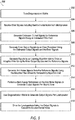
- FIG. 5 illustrates an example process 500 for using a diagonalization filter matrix 418 to perform active noise cancellation in a multichannel ANC system 400.
- the process 500 may be performed using an audio processor programmed to perform the operations described in detail above with respect to FIG. 4 .
- the diagonalization filter matrix 418 is designed and tuned. In the offline acoustic tuning and design of the diagonalization filter matrix 418, the diagonalization filter matrix 418 is tuned to group the loudspeakers 422 based on acoustic measurement data of the loudspeakers 422 to microphone 408 transfer functions. Further aspects of the design and tuning of the diagonalization filter matrix 418 are described above with regard to FIGS. 1-2 .
- the audio processor receives error signals 426 generated from microphones 408.
- the error signals 426 may be generated per sound zone.
- each sound zone may include one or more loudspeakers 422 and one corresponding microphone 408.
- the audio processor generates estimated output signals 438 for the reference signals 402 using an estimated path filter 436.
- the estimated path filter 436 receives frequency domain reference signals 445 generated by the FFT 442 from the reference signals 402, and uses the estimated function ⁇ m [ k ] to provides an estimated effect on an audio signal radiated by speakers and traversing the acoustic physical path 424 diagonalized by the filter matrix 418.
- the audio processor generates error output signals using an error processor 440, using the estimated output signals 438 and the error signals 426.
- the error processor 440 may receive frequency domain error signals 440 generated by the FFT 428 from the error signals 426.
- the error processor 440 may produce error processing output signals 443 in the form ⁇ r,m [ k,n ] representing the time dependent, processed microphone frequency domain error signals 440 using the estimated output signals 438.
- the audio processor generates LAU output 446 signals using the LAU 444 to drive the adaptive filter 410.
- the LAU 444 may receive the error processing output signals 443 and the frequency domain reference signals 445, and may implement various learning algorithms, such as least mean squares (LMS), recursive least mean squares (RLMS), normalized least mean squares (NLMS), or any other suitable learning algorithm to generate LAU output 446 signals that best minimize the environmental noise when processed by the adaptive filter 410.
- LMS least mean squares
- RLMS recursive least mean squares
- NLMS normalized least mean squares
- the audio processor generates anti-noise signals 416 from the reference signals 402 using the adaptive filter 410 driven by the LAU output 446 of the LAU 444.
- the adaptive filter 410 may receive the reference signals 402, and filter the reference signals 402 according to the LAU output 446 to produce the desired, anti-noise signal 416 as output.
- the audio processor performs a sum across references 414 on the adaptive filter 410 outputs to generate anti-noise signals 416 (i.e., per sound zone).
- the adaptive filter 410 may provide anti-noise signals 416 per sound zone and per reference signal 402.
- the sum across references 414 may process these anti-noise signals 416 to provide a single sum for each sound zone.
- the audio processor uses the diagonalization filter matrix 418 to generate output signals per loudspeaker 420 from the anti-noise signals 416.
- the anti-noise signals 416 may be provided to the diagonalization filter matrix 418, which may translate the M anti-noise signals 416 into L output signals per loudspeaker 422.
- the audio processor drives the loudspeakers 422 using the output signals per loudspeaker 420 to cancel the environmental noise.
- the loudspeakers 422 may, accordingly, produce speaker outputs as an acoustical sound wave of the anti-noise to cancel the environmental noise.
- Computing devices described herein generally include computer-executable instructions, where the instructions may be executable by one or more computing devices such as those listed above.
- Computer-executable instructions may be compiled or interpreted from computer programs created using a variety of programming languages and/or technologies, including, without limitation, and either alone or in combination, JavaTM, C, C++, C#, Visual Basic, Java Script, Perl, etc.
- a processor e.g., a microprocessor
- receives instructions e.g., from a memory, a computer-readable medium, etc., and executes these instructions, thereby performing one or more processes, including one or more of the processes described herein.
- Such instructions and other data may be stored and transmitted using a variety of computer-readable media.
Landscapes
- Physics & Mathematics (AREA)
- Engineering & Computer Science (AREA)
- Acoustics & Sound (AREA)
- Multimedia (AREA)
- Signal Processing (AREA)
- Soundproofing, Sound Blocking, And Sound Damping (AREA)
Abstract
Description
- Aspects of the disclosure generally relate to active noise cancellation systems utilizing a diagonalization filter matrix.
- Active noise cancellation (ANC) may be used to generate sound waves or anti-noise that destructively interferes with undesired sound waves. Potential sources of undesired noise may come from undesired voices, heating, ventilation, and air conditioning systems and other environment noise in a room listening space. Potential sources may also come from vehicle engine, tire interaction with the road and other environment noise in a vehicle cabin listening space. ANC systems may use feedforward and feedback structures, to adaptively formulate anti-noise signals. Sensors placed near the potential sources provide the reference signals for the feedforward structure. Sensors placed near the listeners' ear positions provide the error signals for the feedback structure. Once formulated, the destructively-interfering anti-noise sound waves may be produced through loudspeakers to combine with the undesired sound waves in an attempt to cancel the undesired noise. Combination of the anti-noise sound waves and the undesired sound waves can eliminate or minimize perception of the undesired sound waves by one or more listeners within a listening space.
- Sound zones may be generated using speaker arrays and audio processing techniques providing acoustic isolation. Using such a system, different sound material may be delivered in different zones with limited interfering signals from adjacent sound zones. In order to realize the sound zones, a system may be designed using learning algorithm to adjust the response of multiple sound sources to approximate the desired sound field in the reproduction region.
- In one or more illustrative examples, an active noise cancellation system uses a diagonalization matrix to process anti-noise signals. The system realizes sound zones, each including one or more microphones and one or more loudspeakers. The system includes a diagonalization matrix, which is designed offline, to realize the sound zones. The system further includes an audio processor programmed to generate anti-noise signals for each sound zone, based on the reference signals and feedback signals, through an adaptive filter system, using an estimated acoustic transfer function that provides an estimated effect on sound waves traversing the physical path. The adaptive filters are driven by a learning algorithm unit. The learning algorithm unit is based in part on the feedback error signals, the reference signals, and the filtered reference signals by the estimated acoustic transfer functions combined with the diagonalization matrix. The anti-noise signals include signals per sound zone. The system performs a sum across filtered references on the adaptive filter output signals, to generate a set of anti-noise signals per sound zone; processes the set of anti-noise signals using a diagonalization matrix to generate a set of output signals per loudspeaker; and drives the loudspeakers with the output signals per loudspeaker to apply the anti-noise signals to cancel the environmental noise in each zone.
- In one or more illustrative examples, an active noise cancellation method, using a diagonalization matrix, performs cancelling of environmental noise. Estimated output signals of the reference signals are generated using an estimated filter path transfer function that provides an estimated effect on sound waves traversing a physical path, the estimated filter path transfer function performing processing according to a diagonalization matrix and reference signals. Preliminary anti-noise signals are generated from the reference signals using an adaptive filter driven by learning unit signals received from a learning algorithm unit. The learning unit signals are based in part on error output signals generated from the estimated output signals. The anti-noise signals include signals per sound zone and per reference signal. Each sound zone includes a microphone and one or more loudspeakers. A sum across references is performed on the preliminary anti-noise signals to generate a set of output signals per sound zone. The set of output signals are processed by the diagonalization matrix to generate a set of output signals per loudspeaker. The loudspeakers are driven using the output signals per loudspeaker to apply the anti-noise signals to cancel the environmental noise.
-
- FIG. 1 illustrates an example sound system including two sound zones;
- FIG. 2 illustrates an example half signal flow of a system for tuning the filter matrices of

FIG. 1 ; - FIG. 3 illustrates an example ANC system and an example physical environment;
- FIG. 4 illustrates an example multichannel ANC system using a diagonalization filter matrix to perform ANC in terms of sound zones; and
- FIG. 5 illustrates an example process for using a diagonalization filter matrix to perform active noise cancellation in an ANC system.
- As required, detailed embodiments of the present invention are disclosed herein; however, it is to be understood that the disclosed embodiments are merely exemplary of the invention that may be embodied in various and alternative forms. The figures are not necessarily to scale; some features may be exaggerated or minimized to show details of particular components. Therefore, specific structural and functional details disclosed herein are not to be interpreted as limiting, but merely as a representative basis for teaching one skilled in the art to variously employ the present invention.
- Traditionally, active noise cancellation systems use Least Means Square (LMS)-based algorithms, such as Filtered-x Least Means Square (FxLMS) or other variants. Such schemes require a large amount of input channels of reference and feedback microphone signals, as well as a large amount of output channels of speakers. Traditional algorithms usually employ a large filter system, which is adaptive in operation. The performance of noise cancellation relies on the convergence of the entire filter system. Due to the complex acoustic environment and highly limited adaptation time, optimal convergence is usually difficult to achieve, which leads to unsatisfying performance.
- This disclosure combines an active noise cancellation (ANC) system with a diagonalization filter matrix. This combination simplifies cabin acoustic management by diagonalizing a speaker-to-microphone transfer function matrix of the ANC. By combining the diagonalization matrix with ANC, the disclosure separates the noise cancellation effort into (i) offline acoustic tuning, i.e., designing of the diagonalization filter matrix, and (ii) real-time adaptation of the decoupled, simplified ANC filter system. Thus, using the diagonalization matrix to cut down the computational complexity, the system yields a faster convergence rate and improves the cancellation performance.
-
FIG. 1 illustrates anexample system 100 including two sound zones. Sound zones may be implemented in various settings, such as for different seating positions in a vehicle interior. In the depictedsystem 100, the audio signals and transfer functions are frequency domain signals and functions, which have corresponding time domain signals and functions, respectively. The first sound zone input audio signal Y1 (z) is intended for reproduction in the first sound zone Z1 (z), while the second sound zone input audio signal Y2 (z) is intended for reproduction in the second sound zone Z2 (z). Notably, the illustrated sound zone system is a one-way system, without feedback. It should be noted that the illustration of two sound zones is provided as a minimal version for ease of explanation, and systems having a greater number of sound zones may be used. - In the illustrated example, the input audio signals Y1 (z) and Y2 (z) are pre-filtered by inverse filters,
 ,
, , and
, and . The filter output signals are combined as illustrated in
FIG. 1 . Specifically, the signal U 1(z) supplied to the first loudspeaker can be expressed as:

- The first loudspeaker radiates the signal U 1(z) as an acoustic signal that traverses through the physical paths S11 (z) and S12 (z) and arrives in the first sound zone and the second sound zone, respectively. The second loudspeaker radiates the signal U 2(z) as an acoustic signal that traverses through the physical paths S21 (z) and S22 (z) and arrives in the first sound zone and the second sound zone, respectively. Ideally, the sound signals actually present within the two sound zones are denoted as Z1 (z) and Z2 (z), respectively, wherein:

 ,
, ,
, , and
, and and the room transfer functions S 11(z),S 21(z),S 12(z) and S 22(z). Ideally, H 12(z) and H 21(z) are equal to 0.
- The above equations 1-4 may also be written in matrix form, wherein
equations 
 is a 2x2 matrix representing the diagonalization filter transfer functions


- From the above equation 7, it can be seen that if:
 is equal to the inverse of the room impulse response matrix, S -1(z) plus an additional delay of N samples (which represents at least the acoustic delay), then the acoustic signal arriving in the first zone Z 1(z) equals the first sound zone signal Y 1(z), and the acoustic signal arriving in the second zone Z 2(z) equals the second sound zone signal Y 2(z), although delayed by the delay of N samples as compared to the input signals. That is:


- Thus, designing a sound zone reproduction system is, from a mathematical point of view, an issue of inverting the transfer function matrix S(z), which represents the room impulse responses in the frequency domain, i.e., an issue of diagonalizing the overall system transfer function matrix by designing the diagonalization matrix. This computation can be performed offline, before the zone sound reproduction system is used. Various methods are known for matrix inversion. For example, the inverse of a square matrix may be theoretically determined as follows:


U.S. Patent Publication No. 2015/350805 , titled "Sound wave field generation," which is incorporated by reference herein in its entirety. -
FIG. 2 illustrates an example 200 half signal flow of a system for tuning thediagonalization filter matrices of
FIG. 1 . For instance, the details shown inFIG. 2 correspond to the filtering performed for the processing of the input signal Y1 (z). Generally, the illustrated system receives the input signal Y1 (z), and processes the signal Y1 (z) using the filter matricesand to generate the loudspeaker signals U1 (z) and U2 (z). U1 (z) traverses through the physical paths S11 (z) and S12 (z) and arrives in the first sound zone and the second sound zone, respectively. Similarly, U2 (z) traverses through the physical paths S21 (z) and S22 (z) and arrives in the first sound zone and the second sound zone, respectively. After mixed acoustically and received by the microphones, the output of the
microphone 215 is further compared to the input signal Y1 (z) to generate the error signal E1 (z), and the output of themicrophone 216 is used to generate the error signal E2 (z). By adjustingand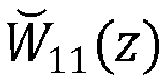 , the error signals E1 (z) and E2 (z) are minimized, respectively, such that Y1 (z) is reproduced in the first sound zone, and minimized in the second sound zone. A similar signal flow may additionally be provided for the processing of the input signal Y2 (z) according to the filter matrices
 and
and to have Y2 (z) reproduced in the second sound zone, and minimized in the first sound zone.
- More specifically, the input signal Y1 (z) is supplied to four filters 201-204, which form a 2 x 2 matrix of modeled acoustic transfer functions Ŝ11 (z), Ŝ12 (z), Ŝ21 (z) and Ŝ22 (z), and to two
filters and .
.
Filters units learning unit 207 receives signals fromfilters learning unit 208 receives signals fromfilter Filters loudspeakers 209 and 210. - The signal U1 (z) is radiated by a first loudspeaker 209 via
acoustic paths microphones second loudspeaker 210 viaacoustic paths microphones microphones -
FIG. 3 illustrates anexample ANC system 300 and an example physical environment. In theANC system 300, an undesired noise source X(z) may traverse aphysical path 304 to amicrophone 306. Thephysical path 304 may be represented by a frequency domain transfer function P(z), which is unknown. The resultant undesired noise, due to traversal of the noise over thephysical path 304, may be referred to as P(z)X(z). X(z) may be measured using a sensor and acquired through use of an analog-to-digital (A/D) converter. The undesired noise source X(z) may also be used as an input to anadaptive filter 308, which may be included in ananti-noise generator 309. Theadaptive filter 308 may be represented by a frequency domain transfer function W(z). Theadaptive filter 308 may be a digital filter configured to be dynamically adapted to filter an input to produce a desiredanti-noise signal 310 as an output. - The
anti-noise signal 310 and anaudio signal 312 generated by anaudio system 314 may be combined to drive aloudspeaker 316. The combination of theanti-noise signal 310 and theaudio signal 312 may produce the sound wave output from theloudspeaker 316. (Theloudspeaker 316 is represented by a summation operation inFIG. 3 , having aspeaker output 318.) Thespeaker output 318 may be a sound wave that traverses through aphysical path 320 that includes a path from theloudspeaker 316 to themicrophone 306. Thephysical path 320 may be represented inFIG. 3 by a frequency domain transfer function S(z). Thespeaker output 318 and the undesired noise may be received by themicrophone 306 and amicrophone output signal 322 may be generated by themicrophone 306. In other examples, any number of loudspeakers and microphones may be present. - A component representative of the
audio signal 312 may be removed from themicrophone output signal 322, through processing of themicrophone output signal 322. Theaudio signal 312 may be processed to reflect the traversal of thephysical path 320 by the sound wave of theaudio signal 312. This processing may be performed by estimating thephysical path 320 as a modeledacoustic path filter 324, which provides an estimated effect on an audio signal sound wave traversing thephysical path 320. The modeled acoustic path filter 324 is configured to simulate the effect on the sound wave of theaudio signal 312 of traveling through thephysical path 320 and generate anoutput signal 334. InFIG. 3 , the modeled acoustic path filter 324 may be represented as a frequency domain transfer function Ŝ(z). - The
microphone output signal 322 may be processed such that a component representative of theaudio output signal 334 is removed as indicated by asummation operation 326. This may occur by inverting the filtered audio signal at thesummation operation 326 and adding the inverted signal to themicrophone output signal 322. Alternatively, the filtered audio signal could be subtracted or any other mechanism or method to remove the signal could be used. The output of thesummation operation 326 is anerror signal 328, which may represent an audible signal remaining after any destructive interference between theanti-noise signal 310 projected through theloudspeaker 316 and the undesired noise sound originated from X(z). Thesummation operation 326 removing a component representative of theaudio output signal 334 from themicrophone output signal 322 may be considered as being included in theANC system 300. - The
error signal 328 is transmitted to a real-time learning algorithm unit (LAU) 330, which may be included in theanti-noise generator 309. TheLAU 330 may implement various learning algorithms, such as least mean squares (LMS), recursive least mean squares (RLMS), normalized least mean squares (NLMS), or any other suitable learning algorithm. TheLAU 330 also receives as an input the undesired noise source X(z) filtered by the modeledacoustic path filter 324. ALAU output 332 may be an update signal transmitted to theadaptive filter 308. Thus, theadaptive filter 308 is configured to receive the undesired noise source X(z) and theLAU output 332. TheLAU output 332 is transmitted to theadaptive filter 308 in order to more accurately cancel the undesired noise source X(z) by providing theanti-noise signal 310. - ANC schemes such as described in
FIG. 3 require a large amount of input channels of noise source reference and feedback microphone signals, as well as a large amount of output channels of speakers. Moreover, the performance of noise cancellation relies on the convergence of the entire filter system. Due to the complex cabin acoustic environment and highly limited adaptation time, optimal convergence is usually difficult to achieve, which leads to unsatisfying performance. - In such implementations, facing complex cabin acoustic environment, full real-time adaptive algorithms suffer from adaptation time inadequacy and computation resource limits. Such systems, therefore, do not usually produce the optimal solution and leads to unsatisfying cancellation performance.
- Moreover, due to the fully-coupled adaptive filter system W(z), performance of ANC systems such as that shown in
FIG. 3 are sensitive to allmicrophone 306 inputs. Failure of onemicrophone 306 may cause performance degradation in the particular seat/zone associated with the failedmicrophone 306. It may also create performance variation in other seats/zones, as the system tries to adapt to the next possible optimal solution with less input information. -
FIG. 4 illustrates an examplemultichannel ANC system 400 using adiagonalization filter matrix 418 to perform ANC in terms of sound zones. As a convention in thesystem 400, let L be the number of loudspeakers, M be the number of microphones and seating zones, R be the number of reference signals (e.g., channels of measured noise source), [k] be the kth sample in frequency domain, and [n] be the nth sample or nth frame in time domain. As explained in further detail below, themultichannel ANC system 400 may operate in a manner similar to theANC system 300 as described with regard toFIG. 3 , but using the sound zone concepts as described with regard toFIGS. 1-2 to reduce system processing requirements. - More specifically, the R reference signals 402 indicate sensed signals that is physically close to sources of noise, and that traverse a
physical path 404. Because the reference signals 402 are close to the sources, they may offer a signal that is leading in time. The reference signals 402 may be noted as xr [n], where r = 1...R, as a vector of dimension R, representing the time-dependent reference signals 402 in the time domain. Thephysical path 404 may be noted as p r,m [n], where r = 1...R and m = 1...M, as a matrix of R×M, representing the time-dependent transfer functions of the primary paths in the time domain. As discussed in more detail below, the noises originated from the reference signals 402 along with sounds from theloudspeakers 422 are combined in theair 406 and received byM error microphones 408. - The R reference signals 402 may also be input to an
adaptive filter 410, which may be a digital filter configured to dynamically adapt to filter the reference signals 402 to produce a desired,anti-noise signal 416 as output after a sum acrossreferences 414. Theadaptive filter 410 may use the notation of wr,m [n], representing the time dependent adaptive w-filters in time domain, where r = 1... R and m = 1...M, giving a matrix of R×M. As indicated by its name, theadaptive filter 410 changes instantaneously, adapting in time to perform the adaptive function of theANC system 400. - The outputs of the
adaptive filter 410 may be provided to the sum acrossreferences 414 combiner. The sum acrossreferences 414 may provide theanti-noise signal 416, with M outputs in the form of ym [n], where m = 1...M, representing the time dependent anti-noise signals in the time domain per microphone. - However, as the
anti-noise signal 416 include a set of M signals, one pererror microphone 408, theanti-noise signal 416 require translation in order to be provided to theL loudspeakers 422. Theanti-noise signal 416 may, accordingly, be provided to thediagonalization filter matrix 418, which may translate the Manti-noise signal 416 into L output signals perloudspeaker 420. Thediagonalization filter matrix 418 may utilize the notation, where m = 1...M and l = 1... L, giving a matrix of M×L, representing the time independent, off-line trained, diagonalization filters in time domain. Notably, the
diagonalization filter matrix 418 is preprogrammed such as described above with respect to the training done inFIG. 2 . In contrast to theadaptive filter 410, thediagonalization filter matrix 418 is fixed and does not adjust during operation of theANC system 400. The output signals perloudspeaker 420 may be referenced in the form of yl [n], where l = 1...L, representing the time-dependent speaker input signals in the time domain. - The 418 output signals per
loudspeaker 420 may be applied to the inputs to theloudspeakers 422. Based on the signals perloudspeaker 420, theloudspeakers 422 may, accordingly, produce speaker outputs as acoustical sound waves that traverse an acousticphysical path 424 from theloudspeakers 422 via theair 406 to theerror microphones 408. Thephysical path 424 may be represented by the transfer function sl,m [n], where l =1... L and m = 1...M, creating a matrix of L×M, representing the time dependent transfer functions of the acoustic paths in the time domain. - Thus, both the R reference signals 402 traversing the primary
physical path 404 and the speaker outputs traversing the acousticphysical path 424 are combined in theair 406 to be received by theM error microphones 408. TheM error microphones 408 may generate M error signals 426. The error signals 426 may be referenced in the form em [n], where m = 1...M, the vector of dimension M , representing the error microphone signals in time domain. - A Fast Fourier Transform (FFT) 428 may be utilized to convert the error signals 426 into frequency domain error signals 440. The frequency domain error signals 440 may be referenced as Em [k,n], where m = 1...M, vector of dimension M, representing the time dependent error microphone signals in the frequency domain.
- The R reference signals 402 may also be input to a
FFT 442, thereby generating frequency-domain reference signals 445. The frequency domain reference signals 445 may be noted as Xr [k,n], where r = 1... R, the vector of dimension R , representing the time-dependent reference signals in the frequency domain. - The frequency domain reference signals 445 may be processed to reflect the effect of traversal through the acoustic
physical path 424 in combination with the diagonalization filtering by 418. This processing may be performed by combining the modeledphysical path 424 together with thediagonalization filter matrix 418, with a resultant diagonalizedestimated path filter 436. The estimated path filter 436 may be formed according to the equation quantity may represent the time independent, off-line trained, design solution of the
diagonalization filter matrix 418 in the frequency domain, where m = 1...M and l = 1...L, giving a matrix of M × L. The Ŝl,m [n] quantity may represent the time independent, estimated transfer functions of theacoustic paths 424 in the frequency domain. Operator diag() is used to extract the diagonal entries, converting the M × M matrix into a vector of dimension M. - The estimated path filter 436 may provide an estimated
output signal 438 representing the time dependent, processed frequency-domain reference signals 445 (taking thediagonalization filter matrix 418 into account) in the frequency domain. The estimatedoutput signal 438 may be referred to in the form X̃r,m [k,n], where r = 1...R and m = 1...M, with a matrix of R×M. - The
error processor 441 may receive the frequency domain error signals 440 and the estimated output signals 438. Theerror processor 440 may produce errorprocessing output signals 443 in the form Ẽr,m [k,n], representing the time dependent, processed microphone frequency domain error signals 440 (using the estimatedoutput signals 438 based on the frequency-domain reference signals 445), in the frequency domain, where r = 1...R and m = 1...M, with a matrix of R×M. Theerror processor 441 may perform processing according to the equation Ẽr,m [k,n] = X̃*r,m [k,n]Em [k,n], where X̃* r,m [k,n] is the complex conjugate of X̃r,m [k,n], and Em [k,n] represents the time dependent error microphone signals 440 in the frequency domain, where m = 1...M, with a vector of dimension M. - The error processing output signals 443 may be provided to a learning algorithm unit (LAU) 444. The
LAU 444 may also receive as an input the frequency-domain reference signals 445. TheLAU 444 may implement various learning algorithms, such as least mean squares (LMS), recursive least mean squares (RLMS), normalized least mean squares (NLMS), or any other suitable learning algorithm. - Using the received
inputs LAU 444 generates anLAU output 446. TheLAU output 446 may be provided to theadaptive filter 410, to direct theadaptive filter 410 to dynamically adapt to filter the reference signals 402 to produce the desired,anti-noise signals 416 as output. In some cases, theLAU 444 may also receive as input one ormore tuning parameters 448. In an example, atuning parameter 448 of µ[k] may be provided to theLAU 444. The parameter µ[k] may represent the time independent adaptation step size in frequency domain. It should be noted that this is merely one example, andother tuning parameters 448 are possible. - The
diagonalization filter matrix 418 groups the speakers with filters, separates the speaker transfer functions zone-by-zone, tunes and decouples the cabin acoustics offline, and adapts for noise cancellation based on independent microphone feedback in real time. This combination of using thediagonalization filter matrix 418 in themultichannel ANC system 400 simplifies cabin acoustic management by diagonalizing a speaker-to-microphone transfer function matrix of the ANC. By combining thediagonalization filter matrix 418 with ANC, the illustratedsystem 400 separates the noise cancellation effort into (i) offline acoustic tuning, i.e., designing of thediagonalization filter matrix 418, and (ii) real-time adaptation of the decoupled,simplified ANC system 400. - In the offline acoustic tuning and design of the
diagonalization filter matrix 418, thediagonalization filter matrix 418 is tuned to group theloudspeakers 422 based on acoustic measurement data of theloudspeakers 422 tomicrophone 408 transfer functions. One example of designing thisdiagonalization filter matrix 418 is demonstrated in the Individual Sound Zone (ISZ) functionality described in detail inU.S. Patent Publication No. 2015/350805 as mentioned above. Because this learning session occurs offline, the designing of thediagonalization filter matrix 418 may be performed without pressure on computation time and or runtime computational resources, which enables a comprehensive search for the optimal solution. With the optimal solution of thediagonalization filter matrix 418 being calculated, individual sound zones are then formulated. Theloudspeakers 422 are therefore grouped by filters and cooperate in a designed way to deliver the sound at each of theerror microphones 408 independently, with minimal interference between zones/error microphones 408. - In the real time adaptive operation, using the
loudspeakers 422 as grouped by thediagonalization filter matrix 418, adaptive cancellation filters are decoupled by zones. Using LMS-based control, thesystem 400 adapts based on independent microphone feedback error signals 426 from each zone, also on the reference signals 402. As opposed to providing outputs for eachloudspeaker 422, in this operation one set ofadaptive filters 410 only provides one output for each zone. The single zone output is then up-mixed using the pre-tuneddiagonalization filter matrix 418, maintaining theloudspeaker 422 cooperation for minimal zone-to-zone interference. This decoupled setting reduces the number of inputs and outputs of adaptive cancellation filters 410, thereby promising faster convergence rate and better cancellation performance. - Thus, by separating the cancellation effort into offline acoustic tuning and real-time adaptation, the
system 400 decouples the complex cabin acoustics by constructing thediagonalization filter matrix 418, with adequate search time and computational resource, and simplifies the adaptive cancellation filter system by reducing the input and output channel number. Overall the advantages of faster convergence rate and better cancellation performance are gained. - Furthermore, because the
ANC system 400 is decoupled, it is more robust. Performance in one zone has minimal impact on other zones. Failure of anymicrophone 408 may only cause localized performance degradation constrained in the corresponding seats/zones, maintaining the performance of other seats/zones, due to the fact that the zones are independent from one other. -
FIG. 5 illustrates anexample process 500 for using adiagonalization filter matrix 418 to perform active noise cancellation in amultichannel ANC system 400. In an example, theprocess 500 may be performed using an audio processor programmed to perform the operations described in detail above with respect toFIG. 4 . - At 502, the
diagonalization filter matrix 418 is designed and tuned. In the offline acoustic tuning and design of thediagonalization filter matrix 418, thediagonalization filter matrix 418 is tuned to group theloudspeakers 422 based on acoustic measurement data of theloudspeakers 422 tomicrophone 408 transfer functions. Further aspects of the design and tuning of thediagonalization filter matrix 418 are described above with regard toFIGS. 1-2 . - At 504, the audio processor receives error signals 426 generated from
microphones 408. The error signals 426 may be generated per sound zone. In an example, each sound zone may include one ormore loudspeakers 422 and one correspondingmicrophone 408. - At 506, the audio processor generates estimated
output signals 438 for the reference signals 402 using an estimatedpath filter 436. In an example, the estimated path filter 436 receives frequency domain reference signals 445 generated by theFFT 442 from the reference signals 402, and uses the estimated function Ŝm [k] to provides an estimated effect on an audio signal radiated by speakers and traversing the acousticphysical path 424 diagonalized by thefilter matrix 418. - At 508, the audio processor generates error output signals using an
error processor 440, using the estimatedoutput signals 438 and the error signals 426. In an example, theerror processor 440 may receive frequency domain error signals 440 generated by theFFT 428 from the error signals 426. Theerror processor 440 may produce errorprocessing output signals 443 in the form Ẽr,m [k,n] representing the time dependent, processed microphone frequency domain error signals 440 using the estimated output signals 438. - At 510, the audio processor generates
LAU output 446 signals using theLAU 444 to drive theadaptive filter 410. In an example, theLAU 444 may receive the errorprocessing output signals 443 and the frequency domain reference signals 445, and may implement various learning algorithms, such as least mean squares (LMS), recursive least mean squares (RLMS), normalized least mean squares (NLMS), or any other suitable learning algorithm to generateLAU output 446 signals that best minimize the environmental noise when processed by theadaptive filter 410. - At 512, the audio processor generates
anti-noise signals 416 from the reference signals 402 using theadaptive filter 410 driven by theLAU output 446 of theLAU 444. In an example, theadaptive filter 410 may receive the reference signals 402, and filter the reference signals 402 according to theLAU output 446 to produce the desired,anti-noise signal 416 as output. - At 514, the audio processor performs a sum across
references 414 on theadaptive filter 410 outputs to generate anti-noise signals 416 (i.e., per sound zone). In an example, theadaptive filter 410 may provideanti-noise signals 416 per sound zone and perreference signal 402. The sum acrossreferences 414 may process theseanti-noise signals 416 to provide a single sum for each sound zone. - At 516, the audio processor uses the
diagonalization filter matrix 418 to generate output signals perloudspeaker 420 from the anti-noise signals 416. In an example, theanti-noise signals 416 may be provided to thediagonalization filter matrix 418, which may translate the Manti-noise signals 416 into L output signals perloudspeaker 422. - At 518, the audio processor drives the
loudspeakers 422 using the output signals perloudspeaker 420 to cancel the environmental noise. Theloudspeakers 422 may, accordingly, produce speaker outputs as an acoustical sound wave of the anti-noise to cancel the environmental noise. Afteroperation 516, theprocess 500 ends. - Computing devices described herein generally include computer-executable instructions, where the instructions may be executable by one or more computing devices such as those listed above. Computer-executable instructions may be compiled or interpreted from computer programs created using a variety of programming languages and/or technologies, including, without limitation, and either alone or in combination, Java™, C, C++, C#, Visual Basic, Java Script, Perl, etc. In general, a processor (e.g., a microprocessor) receives instructions, e.g., from a memory, a computer-readable medium, etc., and executes these instructions, thereby performing one or more processes, including one or more of the processes described herein. Such instructions and other data may be stored and transmitted using a variety of computer-readable media.
- While exemplary embodiments are described above, it is not intended that these embodiments describe all possible forms of the invention. Rather, the words used in the specification are words of description rather than limitation, and it is understood that various changes may be made without departing from the spirit and scope of the invention. Additionally, the features of various implementing embodiments may be combined to form further embodiments of the invention.
Claims (15)
- An active noise cancellation system, using a diagonalization matrix to process anti-noise signals, for cancelling environmental noise in a plurality of sound zones, comprising:a plurality of sound zones, each including one or more microphones and one or more loudspeakers;a diagonalization matrix; andan audio processor programmed to:generate adaptive filter output signals, based on reference signals and feedback error signals through a set of adaptive filters, using an estimated acoustic transfer function that provides an estimated effect on sound waves traversing a physical path, the set of adaptive filters being driven by a learning algorithm unit based in part on the feedback error signals, the reference signals, and the reference signals filtered by the estimated acoustic transfer functions combined with the diagonalization matrix;perform a sum across references on the adaptive filter output signals to generate a set of anti-noise signals;process the set of anti-noise signals using the diagonalization matrix to generate a set of output signals per loudspeaker; anddrive the loudspeakers using the output signals per loudspeaker to apply the anti-noise signals to cancel the environmental noise in each zone.
- The active noise cancellation system of claim 1, wherein the learning algorithm unit utilizes a Least Means Square (LMS)-based algorithm to minimize the environmental noise resulting from application of signals from the learning algorithm unit to the adaptive filter.
- The active noise cancellation system of claim 1, wherein the audio processor is further programmed to receive error signals including the environmental noise from the microphones.
- The active noise cancellation system of claim 1, wherein the sound zones are seats of a vehicle cabin.
- The active noise cancellation system of claim 1, wherein the audio processor is further programmed to generate frequency domain reference signals from the reference signals using a Fast Fourier Transform, and to provide the frequency domain reference signals to an estimated path filter and to the learning algorithm unit.
- The active noise cancellation system of claim 1, wherein the audio processor is further programmed to:generate frequency domain error signals from the error signals received from the microphones using a Fast Fourier Transform;provide the frequency domain error signals to an error processor; anduse the error processor to generate the feedback error signals from the estimated output signals and the frequency domain error signals.
- The active noise cancellation system of claim 1, wherein the audio processor is further programmed to provide a tuning parameter to the learning algorithm unit that represents time-independent adaptation step size in frequency domain.
- The active noise cancellation system of claim 1, wherein the diagonalization matrix is precomputed before runtime of the active noise cancellation system.
- The active noise cancellation system of claim 1, wherein the diagonalization matrix is designed for a room according to inverting a transfer function matrix including measurements that represent impulse responses for a room in a frequency domain.
- An active noise cancellation method, using a diagonalization matrix, for cancelling environmental noise comprising:generating estimated output signals of the reference signals using an estimated filter path transfer function that provides an estimated effect on sound waves traversing a physical path, the estimated filter path transfer function being precomputed and diagonalized based on a modeled acoustic transfer function and the diagonalization matrix, and performing processing according to reference signals;generating preliminary anti-noise signals from the reference signals using an adaptive filter driven by learning unit signals received from a learning algorithm unit, the learning unit signals based in part on error output signals generated from the estimated output signals, the anti-noise signals including signals per sound zone and per reference signal, each sound zone including a microphone and one or more loudspeakers;performing a sum across references on the preliminary anti-noise signals to generate a set of anti-noise signals per sound zone;processing the set of output signals by the diagonalization matrix to generate a set of output signals per loudspeaker; anddriving the loudspeakers using the output signals per loudspeaker to apply the anti-noise signals to cancel the environmental noise.
- The active noise cancellation method of claim 10, further comprising utilizing a Least Means Square (LMS)-based algorithm by the learning algorithm unit to minimize the environmental noise resulting from application of the learning unit signals to the adaptive filter.
- The active noise cancellation method of claim 10, further comprising:receiving error signals including the environmental noise from the microphones;generating frequency domain reference signals from the reference signals using a Fast Fourier Transform; andproviding the frequency domain reference signals to the estimated filter path and to the learning algorithm unit.
- The active noise cancellation method of claim 10, further comprising:generating frequency domain error signals from the error signals received from the microphones using a Fast Fourier Transform;providing the frequency domain error signals to an error processor; andusing the error processor, generating the error output signals from the estimated output signals and the frequency domain error signals.
- The active noise cancellation method of claim 10, further comprising providing a tuning parameter to the learning algorithm unit that represents time-independent adaptation step size in frequency domain.
- The active noise cancellation method of claim 10, further comprising designing the diagonalization matrix for a room by measuring a transfer function matrix representing impulse responses for a room in a frequency domain, and inverting the transfer function matrix, wherein the diagonalization matrix is precomputed before runtime of the active noise cancellation system.
Applications Claiming Priority (1)
| Application Number | Priority Date | Filing Date | Title |
|---|---|---|---|
| US15/915,941 US10339912B1 (en) | 2018-03-08 | 2018-03-08 | Active noise cancellation system utilizing a diagonalization filter matrix |
Publications (2)
| Publication Number | Publication Date |
|---|---|
| EP3537431A1 true EP3537431A1 (en) | 2019-09-11 |
| EP3537431B1 EP3537431B1 (en) | 2023-08-16 |
Family
ID=65686773
Family Applications (1)
| Application Number | Title | Priority Date | Filing Date |
|---|---|---|---|
| EP19160668.0A Active EP3537431B1 (en) | 2018-03-08 | 2019-03-05 | Active noise cancellation system utilizing a diagonalization filter matrix |
Country Status (5)
| Country | Link |
|---|---|
| US (1) | US10339912B1 (en) |
| EP (1) | EP3537431B1 (en) |
| JP (1) | JP7374595B2 (en) |
| KR (1) | KR102557002B1 (en) |
| CN (1) | CN110246480B (en) |
Cited By (1)
| Publication number | Priority date | Publication date | Assignee | Title |
|---|---|---|---|---|
| EP4270380A1 (en) * | 2022-04-27 | 2023-11-01 | Harman International Industries, Inc. | Fast adapting high frequency remote microphone noise cancellation |
Families Citing this family (10)
| Publication number | Priority date | Publication date | Assignee | Title |
|---|---|---|---|---|
| WO2021051377A1 (en) * | 2019-09-20 | 2021-03-25 | Harman International Industries, Incorporated | Room calibration based on gaussian distribution and k-nearestneighbors algorithm |
| EP4111444B1 (en) * | 2020-02-25 | 2024-11-13 | Bose Corporation | Narrowband cancellation |
| CN111554264B (en) * | 2020-05-13 | 2023-02-10 | 西安艾科特声学科技有限公司 | Fault detection method and device of active noise reduction equipment |
| CN112017626B (en) * | 2020-08-21 | 2024-02-06 | 中车株洲电力机车有限公司 | Active noise reduction method for rail transit vehicle and cab |
| US11100911B1 (en) * | 2020-09-18 | 2021-08-24 | Bose Corporation | Systems and methods for adapting estimated secondary path |
| CN117280414A (en) * | 2021-05-08 | 2023-12-22 | 赛轮思经营公司 | Noise reduction based on dynamic neural network |
| CN114566137B (en) * | 2021-12-31 | 2025-05-27 | 苏州茹声电子有限公司 | Vehicle road noise control method and system based on active noise reduction, and storage medium |
| WO2023133033A1 (en) * | 2022-01-07 | 2023-07-13 | Analog Devices Inc. | Personalized audio zone via a combination of ultrasonic transducers and low-frequency speaker |
| CN116469365A (en) * | 2023-05-09 | 2023-07-21 | 重庆长安汽车股份有限公司 | Noise control system, method and computer equipment with adjustable multi-region noise reduction performance |
| CN120108410B (en) * | 2023-12-04 | 2026-03-31 | 北京嘀嘀无限科技发展有限公司 | Methods for processing audio signals, electronic devices, and vehicles |
Citations (2)
| Publication number | Priority date | Publication date | Assignee | Title |
|---|---|---|---|---|
| US20150350805A1 (en) | 2014-04-07 | 2015-12-03 | Harman Becker Automotive Systems Gmbh | Sound wave field generation |
| EP3024252A1 (en) * | 2014-11-19 | 2016-05-25 | Harman Becker Automotive Systems GmbH | Sound system for establishing a sound zone |
Family Cites Families (31)
| Publication number | Priority date | Publication date | Assignee | Title |
|---|---|---|---|---|
| JPH09160568A (en) * | 1995-12-13 | 1997-06-20 | Fujitsu Ltd | Active noise control system in three-dimensional space |
| US5953428A (en) * | 1996-04-30 | 1999-09-14 | Lucent Technologies Inc. | Feedback method of noise control having multiple inputs and outputs |
| FI973455A7 (en) * | 1997-08-22 | 1999-02-23 | Nokia Corp | Method and arrangement for reducing noise in a space by generating counter noise |
| ATE402468T1 (en) * | 2004-03-17 | 2008-08-15 | Harman Becker Automotive Sys | SOUND TUNING DEVICE, USE THEREOF AND SOUND TUNING METHOD |
| JPWO2007013281A1 (en) * | 2005-07-27 | 2009-02-05 | パナソニック株式会社 | Active vibration noise control device |
| EP1947642B1 (en) * | 2007-01-16 | 2018-06-13 | Apple Inc. | Active noise control system |
| EP2282555B1 (en) * | 2007-09-27 | 2014-03-05 | Harman Becker Automotive Systems GmbH | Automatic bass management |
| US8135140B2 (en) * | 2008-11-20 | 2012-03-13 | Harman International Industries, Incorporated | System for active noise control with audio signal compensation |
| EP2216774B1 (en) * | 2009-01-30 | 2015-09-16 | Harman Becker Automotive Systems GmbH | Adaptive noise control system and method |
| JP5651923B2 (en) * | 2009-04-07 | 2015-01-14 | ソニー株式会社 | Signal processing apparatus and signal processing method |
| GB0906269D0 (en) * | 2009-04-09 | 2009-05-20 | Ntnu Technology Transfer As | Optimal modal beamformer for sensor arrays |
| US8199924B2 (en) * | 2009-04-17 | 2012-06-12 | Harman International Industries, Incorporated | System for active noise control with an infinite impulse response filter |
| US8345888B2 (en) * | 2009-04-28 | 2013-01-01 | Bose Corporation | Digital high frequency phase compensation |
| US8385559B2 (en) * | 2009-12-30 | 2013-02-26 | Robert Bosch Gmbh | Adaptive digital noise canceller |
| EP2362381B1 (en) * | 2010-02-25 | 2019-12-18 | Harman Becker Automotive Systems GmbH | Active noise reduction system |
| EP2624251B1 (en) * | 2012-01-31 | 2014-09-10 | Harman Becker Automotive Systems GmbH | Method of adjusting an anc system |
| EP2629289B1 (en) * | 2012-02-15 | 2022-06-15 | Harman Becker Automotive Systems GmbH | Feedback active noise control system with a long secondary path |
| US8831239B2 (en) * | 2012-04-02 | 2014-09-09 | Bose Corporation | Instability detection and avoidance in a feedback system |
| US9240176B2 (en) * | 2013-02-08 | 2016-01-19 | GM Global Technology Operations LLC | Active noise control system and method |
| EP2816824B1 (en) | 2013-05-24 | 2020-07-01 | Harman Becker Automotive Systems GmbH | Sound system for establishing a sound zone |
| EP2806664B1 (en) | 2013-05-24 | 2020-02-26 | Harman Becker Automotive Systems GmbH | Sound system for establishing a sound zone |
| CN103500575B (en) | 2013-09-24 | 2016-04-20 | 同济大学 | A kind of method predicting active noise control system noise reduction |
| US9854358B2 (en) * | 2014-07-25 | 2017-12-26 | 2236008 Ontario Inc. | System and method for mitigating audio feedback |
| US20160300563A1 (en) * | 2015-04-13 | 2016-10-13 | Qualcomm Incorporated | Active noise cancellation featuring secondary path estimation |
| US9923550B2 (en) * | 2015-09-16 | 2018-03-20 | Bose Corporation | Estimating secondary path phase in active noise control |
| US9728179B2 (en) * | 2015-10-16 | 2017-08-08 | Avnera Corporation | Calibration and stabilization of an active noise cancelation system |
| EP3182407B1 (en) * | 2015-12-17 | 2020-03-11 | Harman Becker Automotive Systems GmbH | Active noise control by adaptive noise filtering |
| EP3226580B1 (en) * | 2016-03-31 | 2020-04-29 | Harman Becker Automotive Systems GmbH | Automatic noise control for a vehicle seat |
| EP3633670A1 (en) * | 2016-05-11 | 2020-04-08 | Harman Becker Automotive Systems GmbH | Method and system for selecting sensor locations on a vehicle for active road noise control |
| TWI611704B (en) * | 2016-07-15 | 2018-01-11 | 驊訊電子企業股份有限公司 | Method, system for self-tuning active noise cancellation and headset apparatus |
| US10034092B1 (en) * | 2016-09-22 | 2018-07-24 | Apple Inc. | Spatial headphone transparency |
-
2018
- 2018-03-08 US US15/915,941 patent/US10339912B1/en active Active
-
2019
- 2019-03-04 JP JP2019038438A patent/JP7374595B2/en active Active
- 2019-03-05 EP EP19160668.0A patent/EP3537431B1/en active Active
- 2019-03-07 KR KR1020190026054A patent/KR102557002B1/en active Active
- 2019-03-07 CN CN201910171037.3A patent/CN110246480B/en active Active
Patent Citations (2)
| Publication number | Priority date | Publication date | Assignee | Title |
|---|---|---|---|---|
| US20150350805A1 (en) | 2014-04-07 | 2015-12-03 | Harman Becker Automotive Systems Gmbh | Sound wave field generation |
| EP3024252A1 (en) * | 2014-11-19 | 2016-05-25 | Harman Becker Automotive Systems GmbH | Sound system for establishing a sound zone |
Cited By (1)
| Publication number | Priority date | Publication date | Assignee | Title |
|---|---|---|---|---|
| EP4270380A1 (en) * | 2022-04-27 | 2023-11-01 | Harman International Industries, Inc. | Fast adapting high frequency remote microphone noise cancellation |
Also Published As
| Publication number | Publication date |
|---|---|
| JP2019159322A (en) | 2019-09-19 |
| US10339912B1 (en) | 2019-07-02 |
| KR102557002B1 (en) | 2023-07-19 |
| EP3537431B1 (en) | 2023-08-16 |
| KR20190106775A (en) | 2019-09-18 |
| JP7374595B2 (en) | 2023-11-07 |
| CN110246480A (en) | 2019-09-17 |
| CN110246480B (en) | 2024-07-23 |
Similar Documents
| Publication | Publication Date | Title |
|---|---|---|
| EP3537431B1 (en) | Active noise cancellation system utilizing a diagonalization filter matrix | |
| CN101888223B (en) | System and method for active noise control with adaptive speaker selection | |
| EP2239729B1 (en) | Quiet zone control system | |
| Zhang et al. | Deep MCANC: A deep learning approach to multi-channel active noise control | |
| JP6685087B2 (en) | Adaptive noise control system with improved robustness | |
| AU2013241928B2 (en) | Apparatus and method for improving the perceived quality of sound reproduction by combining active noise cancellation and perceptual noise compensation | |
| US8600069B2 (en) | Multi-channel active noise control system with channel equalization | |
| US11043202B2 (en) | Active noise control system, setting method of active noise control system, and audio system | |
| JP7491846B2 (en) | Feedforward Active Noise Control | |
| EP4439550A1 (en) | Active noise reduction method and device for vehicle and storage medium | |
| Shi et al. | Active noise control based on the momentum multichannel normalized filtered-x least mean square algorithm | |
| US12508967B2 (en) | Method for positioning a shaker and use of the shaker for vibration control | |
| de Diego et al. | Multichannel active noise control system for local spectral reshaping of multifrequency noise | |
| CN117311406A (en) | A vibration active control method, test method, device, vehicle, equipment and medium based on feedback FXLMS algorithm | |
| Opinto et al. | Performance Analysis of Feedback MIMO ANC in Experimental Automotive Environment | |
| Oh et al. | Development of an active road noise control system | |
| Okajima et al. | Dual active noise control with common sensors | |
| JP2023170080A (en) | Active noise control system | |
| JP4590389B2 (en) | Active vibration noise control device | |
| Islam et al. | Real-time implementation of a user-selective active sound control seat based on auditory scene analysis | |
| JP7734229B1 (en) | Active vibration and noise reduction device | |
| De Diego et al. | Some practical insights in multichannel active noise control equalization | |
| JPH0844375A (en) | Noise canceling apparatus and noise canceling method | |
| JP2020140044A (en) | Active noise control system | |
| Toyooka et al. | Hybrid active noise control system for remote microphone based virtual sensing with two compensation filters |
Legal Events
| Date | Code | Title | Description |
|---|---|---|---|
| PUAI | Public reference made under article 153(3) epc to a published international application that has entered the european phase |
Free format text: ORIGINAL CODE: 0009012 |
|
| STAA | Information on the status of an ep patent application or granted ep patent |
Free format text: STATUS: THE APPLICATION HAS BEEN PUBLISHED |
|
| AK | Designated contracting states |
Kind code of ref document: A1 Designated state(s): AL AT BE BG CH CY CZ DE DK EE ES FI FR GB GR HR HU IE IS IT LI LT LU LV MC MK MT NL NO PL PT RO RS SE SI SK SM TR |
|
| AX | Request for extension of the european patent |
Extension state: BA ME |
|
| STAA | Information on the status of an ep patent application or granted ep patent |
Free format text: STATUS: REQUEST FOR EXAMINATION WAS MADE |
|
| 17P | Request for examination filed |
Effective date: 20200310 |
|
| RBV | Designated contracting states (corrected) |
Designated state(s): AL AT BE BG CH CY CZ DE DK EE ES FI FR GB GR HR HU IE IS IT LI LT LU LV MC MK MT NL NO PL PT RO RS SE SI SK SM TR |
|
| STAA | Information on the status of an ep patent application or granted ep patent |
Free format text: STATUS: EXAMINATION IS IN PROGRESS |
|
| 17Q | First examination report despatched |
Effective date: 20210217 |
|
| GRAP | Despatch of communication of intention to grant a patent |
Free format text: ORIGINAL CODE: EPIDOSNIGR1 |
|
| STAA | Information on the status of an ep patent application or granted ep patent |
Free format text: STATUS: GRANT OF PATENT IS INTENDED |
|
| INTG | Intention to grant announced |
Effective date: 20230321 |
|
| GRAS | Grant fee paid |
Free format text: ORIGINAL CODE: EPIDOSNIGR3 |
|
| P01 | Opt-out of the competence of the unified patent court (upc) registered |
Effective date: 20230527 |
|
| GRAA | (expected) grant |
Free format text: ORIGINAL CODE: 0009210 |
|
| STAA | Information on the status of an ep patent application or granted ep patent |
Free format text: STATUS: THE PATENT HAS BEEN GRANTED |
|
| AK | Designated contracting states |
Kind code of ref document: B1 Designated state(s): AL AT BE BG CH CY CZ DE DK EE ES FI FR GB GR HR HU IE IS IT LI LT LU LV MC MK MT NL NO PL PT RO RS SE SI SK SM TR |
|
| REG | Reference to a national code |
Ref country code: CH Ref legal event code: EP |
|
| REG | Reference to a national code |
Ref country code: DE Ref legal event code: R096 Ref document number: 602019034930 Country of ref document: DE |
|
| REG | Reference to a national code |
Ref country code: IE Ref legal event code: FG4D |
|
| REG | Reference to a national code |
Ref country code: LT Ref legal event code: MG9D |
|
| REG | Reference to a national code |
Ref country code: NL Ref legal event code: MP Effective date: 20230816 |
|
| REG | Reference to a national code |
Ref country code: AT Ref legal event code: MK05 Ref document number: 1600876 Country of ref document: AT Kind code of ref document: T Effective date: 20230816 |
|
| PG25 | Lapsed in a contracting state [announced via postgrant information from national office to epo] |
Ref country code: GR Free format text: LAPSE BECAUSE OF FAILURE TO SUBMIT A TRANSLATION OF THE DESCRIPTION OR TO PAY THE FEE WITHIN THE PRESCRIBED TIME-LIMIT Effective date: 20231117 |
|
| PG25 | Lapsed in a contracting state [announced via postgrant information from national office to epo] |
Ref country code: IS Free format text: LAPSE BECAUSE OF FAILURE TO SUBMIT A TRANSLATION OF THE DESCRIPTION OR TO PAY THE FEE WITHIN THE PRESCRIBED TIME-LIMIT Effective date: 20231216 |
|
| PG25 | Lapsed in a contracting state [announced via postgrant information from national office to epo] |
Ref country code: SE Free format text: LAPSE BECAUSE OF FAILURE TO SUBMIT A TRANSLATION OF THE DESCRIPTION OR TO PAY THE FEE WITHIN THE PRESCRIBED TIME-LIMIT Effective date: 20230816 Ref country code: RS Free format text: LAPSE BECAUSE OF FAILURE TO SUBMIT A TRANSLATION OF THE DESCRIPTION OR TO PAY THE FEE WITHIN THE PRESCRIBED TIME-LIMIT Effective date: 20230816 Ref country code: PT Free format text: LAPSE BECAUSE OF FAILURE TO SUBMIT A TRANSLATION OF THE DESCRIPTION OR TO PAY THE FEE WITHIN THE PRESCRIBED TIME-LIMIT Effective date: 20231218 Ref country code: NO Free format text: LAPSE BECAUSE OF FAILURE TO SUBMIT A TRANSLATION OF THE DESCRIPTION OR TO PAY THE FEE WITHIN THE PRESCRIBED TIME-LIMIT Effective date: 20231116 Ref country code: NL Free format text: LAPSE BECAUSE OF FAILURE TO SUBMIT A TRANSLATION OF THE DESCRIPTION OR TO PAY THE FEE WITHIN THE PRESCRIBED TIME-LIMIT Effective date: 20230816 Ref country code: LV Free format text: LAPSE BECAUSE OF FAILURE TO SUBMIT A TRANSLATION OF THE DESCRIPTION OR TO PAY THE FEE WITHIN THE PRESCRIBED TIME-LIMIT Effective date: 20230816 Ref country code: LT Free format text: LAPSE BECAUSE OF FAILURE TO SUBMIT A TRANSLATION OF THE DESCRIPTION OR TO PAY THE FEE WITHIN THE PRESCRIBED TIME-LIMIT Effective date: 20230816 Ref country code: IS Free format text: LAPSE BECAUSE OF FAILURE TO SUBMIT A TRANSLATION OF THE DESCRIPTION OR TO PAY THE FEE WITHIN THE PRESCRIBED TIME-LIMIT Effective date: 20231216 Ref country code: HR Free format text: LAPSE BECAUSE OF FAILURE TO SUBMIT A TRANSLATION OF THE DESCRIPTION OR TO PAY THE FEE WITHIN THE PRESCRIBED TIME-LIMIT Effective date: 20230816 Ref country code: GR Free format text: LAPSE BECAUSE OF FAILURE TO SUBMIT A TRANSLATION OF THE DESCRIPTION OR TO PAY THE FEE WITHIN THE PRESCRIBED TIME-LIMIT Effective date: 20231117 Ref country code: FI Free format text: LAPSE BECAUSE OF FAILURE TO SUBMIT A TRANSLATION OF THE DESCRIPTION OR TO PAY THE FEE WITHIN THE PRESCRIBED TIME-LIMIT Effective date: 20230816 Ref country code: AT Free format text: LAPSE BECAUSE OF FAILURE TO SUBMIT A TRANSLATION OF THE DESCRIPTION OR TO PAY THE FEE WITHIN THE PRESCRIBED TIME-LIMIT Effective date: 20230816 |
|
| PG25 | Lapsed in a contracting state [announced via postgrant information from national office to epo] |
Ref country code: PL Free format text: LAPSE BECAUSE OF FAILURE TO SUBMIT A TRANSLATION OF THE DESCRIPTION OR TO PAY THE FEE WITHIN THE PRESCRIBED TIME-LIMIT Effective date: 20230816 |
|
| PG25 | Lapsed in a contracting state [announced via postgrant information from national office to epo] |
Ref country code: ES Free format text: LAPSE BECAUSE OF FAILURE TO SUBMIT A TRANSLATION OF THE DESCRIPTION OR TO PAY THE FEE WITHIN THE PRESCRIBED TIME-LIMIT Effective date: 20230816 |
|
| PG25 | Lapsed in a contracting state [announced via postgrant information from national office to epo] |
Ref country code: SM Free format text: LAPSE BECAUSE OF FAILURE TO SUBMIT A TRANSLATION OF THE DESCRIPTION OR TO PAY THE FEE WITHIN THE PRESCRIBED TIME-LIMIT Effective date: 20230816 Ref country code: RO Free format text: LAPSE BECAUSE OF FAILURE TO SUBMIT A TRANSLATION OF THE DESCRIPTION OR TO PAY THE FEE WITHIN THE PRESCRIBED TIME-LIMIT Effective date: 20230816 Ref country code: ES Free format text: LAPSE BECAUSE OF FAILURE TO SUBMIT A TRANSLATION OF THE DESCRIPTION OR TO PAY THE FEE WITHIN THE PRESCRIBED TIME-LIMIT Effective date: 20230816 Ref country code: EE Free format text: LAPSE BECAUSE OF FAILURE TO SUBMIT A TRANSLATION OF THE DESCRIPTION OR TO PAY THE FEE WITHIN THE PRESCRIBED TIME-LIMIT Effective date: 20230816 Ref country code: DK Free format text: LAPSE BECAUSE OF FAILURE TO SUBMIT A TRANSLATION OF THE DESCRIPTION OR TO PAY THE FEE WITHIN THE PRESCRIBED TIME-LIMIT Effective date: 20230816 Ref country code: CZ Free format text: LAPSE BECAUSE OF FAILURE TO SUBMIT A TRANSLATION OF THE DESCRIPTION OR TO PAY THE FEE WITHIN THE PRESCRIBED TIME-LIMIT Effective date: 20230816 Ref country code: SK Free format text: LAPSE BECAUSE OF FAILURE TO SUBMIT A TRANSLATION OF THE DESCRIPTION OR TO PAY THE FEE WITHIN THE PRESCRIBED TIME-LIMIT Effective date: 20230816 |
|
| REG | Reference to a national code |
Ref country code: DE Ref legal event code: R097 Ref document number: 602019034930 Country of ref document: DE |
|
| PLBE | No opposition filed within time limit |
Free format text: ORIGINAL CODE: 0009261 |
|
| STAA | Information on the status of an ep patent application or granted ep patent |
Free format text: STATUS: NO OPPOSITION FILED WITHIN TIME LIMIT |
|
| 26N | No opposition filed |
Effective date: 20240517 |
|
| PG25 | Lapsed in a contracting state [announced via postgrant information from national office to epo] |
Ref country code: IT Free format text: LAPSE BECAUSE OF FAILURE TO SUBMIT A TRANSLATION OF THE DESCRIPTION OR TO PAY THE FEE WITHIN THE PRESCRIBED TIME-LIMIT Effective date: 20230816 Ref country code: SI Free format text: LAPSE BECAUSE OF FAILURE TO SUBMIT A TRANSLATION OF THE DESCRIPTION OR TO PAY THE FEE WITHIN THE PRESCRIBED TIME-LIMIT Effective date: 20230816 |
|
| REG | Reference to a national code |
Ref country code: CH Ref legal event code: PL |
|
| PG25 | Lapsed in a contracting state [announced via postgrant information from national office to epo] |
Ref country code: BG Free format text: LAPSE BECAUSE OF FAILURE TO SUBMIT A TRANSLATION OF THE DESCRIPTION OR TO PAY THE FEE WITHIN THE PRESCRIBED TIME-LIMIT Effective date: 20230816 |
|
| PG25 | Lapsed in a contracting state [announced via postgrant information from national office to epo] |
Ref country code: LU Free format text: LAPSE BECAUSE OF NON-PAYMENT OF DUE FEES Effective date: 20240305 |
|
| PG25 | Lapsed in a contracting state [announced via postgrant information from national office to epo] |
Ref country code: MC Free format text: LAPSE BECAUSE OF FAILURE TO SUBMIT A TRANSLATION OF THE DESCRIPTION OR TO PAY THE FEE WITHIN THE PRESCRIBED TIME-LIMIT Effective date: 20230816 |
|
| PG25 | Lapsed in a contracting state [announced via postgrant information from national office to epo] |
Ref country code: MC Free format text: LAPSE BECAUSE OF FAILURE TO SUBMIT A TRANSLATION OF THE DESCRIPTION OR TO PAY THE FEE WITHIN THE PRESCRIBED TIME-LIMIT Effective date: 20230816 Ref country code: LU Free format text: LAPSE BECAUSE OF NON-PAYMENT OF DUE FEES Effective date: 20240305 Ref country code: BG Free format text: LAPSE BECAUSE OF FAILURE TO SUBMIT A TRANSLATION OF THE DESCRIPTION OR TO PAY THE FEE WITHIN THE PRESCRIBED TIME-LIMIT Effective date: 20230816 |
|
| REG | Reference to a national code |
Ref country code: BE Ref legal event code: MM Effective date: 20240331 |
|
| PG25 | Lapsed in a contracting state [announced via postgrant information from national office to epo] |
Ref country code: BE Free format text: LAPSE BECAUSE OF NON-PAYMENT OF DUE FEES Effective date: 20240331 |
|
| PG25 | Lapsed in a contracting state [announced via postgrant information from national office to epo] |
Ref country code: FR Free format text: LAPSE BECAUSE OF NON-PAYMENT OF DUE FEES Effective date: 20240331 |
|
| PG25 | Lapsed in a contracting state [announced via postgrant information from national office to epo] |
Ref country code: IE Free format text: LAPSE BECAUSE OF NON-PAYMENT OF DUE FEES Effective date: 20240305 |
|
| PG25 | Lapsed in a contracting state [announced via postgrant information from national office to epo] |
Ref country code: IE Free format text: LAPSE BECAUSE OF NON-PAYMENT OF DUE FEES Effective date: 20240305 Ref country code: FR Free format text: LAPSE BECAUSE OF NON-PAYMENT OF DUE FEES Effective date: 20240331 Ref country code: BE Free format text: LAPSE BECAUSE OF NON-PAYMENT OF DUE FEES Effective date: 20240331 Ref country code: CH Free format text: LAPSE BECAUSE OF NON-PAYMENT OF DUE FEES Effective date: 20240331 |
|
| PG25 | Lapsed in a contracting state [announced via postgrant information from national office to epo] |
Ref country code: CY Free format text: LAPSE BECAUSE OF FAILURE TO SUBMIT A TRANSLATION OF THE DESCRIPTION OR TO PAY THE FEE WITHIN THE PRESCRIBED TIME-LIMIT; INVALID AB INITIO Effective date: 20190305 |
|
| PG25 | Lapsed in a contracting state [announced via postgrant information from national office to epo] |
Ref country code: HU Free format text: LAPSE BECAUSE OF FAILURE TO SUBMIT A TRANSLATION OF THE DESCRIPTION OR TO PAY THE FEE WITHIN THE PRESCRIBED TIME-LIMIT; INVALID AB INITIO Effective date: 20190305 |
|
| PG25 | Lapsed in a contracting state [announced via postgrant information from national office to epo] |
Ref country code: TR Free format text: LAPSE BECAUSE OF FAILURE TO SUBMIT A TRANSLATION OF THE DESCRIPTION OR TO PAY THE FEE WITHIN THE PRESCRIBED TIME-LIMIT Effective date: 20230816 |
|
| PGFP | Annual fee paid to national office [announced via postgrant information from national office to epo] |
Ref country code: GB Payment date: 20260219 Year of fee payment: 8 |
|
| PGFP | Annual fee paid to national office [announced via postgrant information from national office to epo] |
Ref country code: DE Payment date: 20260219 Year of fee payment: 8 |