EP3537380A1 - Coordinate calibration between two-dimensional coordinate system and three-dimensional coordinate system - Google Patents
Coordinate calibration between two-dimensional coordinate system and three-dimensional coordinate system Download PDFInfo
- Publication number
- EP3537380A1 EP3537380A1 EP19161534.3A EP19161534A EP3537380A1 EP 3537380 A1 EP3537380 A1 EP 3537380A1 EP 19161534 A EP19161534 A EP 19161534A EP 3537380 A1 EP3537380 A1 EP 3537380A1
- Authority
- EP
- European Patent Office
- Prior art keywords
- coordinate
- flat plate
- dimensional
- processor
- information
- Prior art date
- Legal status (The legal status is an assumption and is not a legal conclusion. Google has not performed a legal analysis and makes no representation as to the accuracy of the status listed.)
- Granted
Links
Images

Classifications
-
- G—PHYSICS
- G06—COMPUTING OR CALCULATING; COUNTING
- G06T—IMAGE DATA PROCESSING OR GENERATION, IN GENERAL
- G06T7/00—Image analysis
- G06T7/30—Determination of transform parameters for the alignment of images, i.e. image registration
- G06T7/33—Determination of transform parameters for the alignment of images, i.e. image registration using feature-based methods
-
- G—PHYSICS
- G06—COMPUTING OR CALCULATING; COUNTING
- G06T—IMAGE DATA PROCESSING OR GENERATION, IN GENERAL
- G06T7/00—Image analysis
- G06T7/80—Analysis of captured images to determine intrinsic or extrinsic camera parameters, i.e. camera calibration
- G06T7/85—Stereo camera calibration
-
- G—PHYSICS
- G06—COMPUTING OR CALCULATING; COUNTING
- G06F—ELECTRIC DIGITAL DATA PROCESSING
- G06F17/00—Digital computing or data processing equipment or methods, specially adapted for specific functions
- G06F17/10—Complex mathematical operations
- G06F17/16—Matrix or vector computation, e.g. matrix-matrix or matrix-vector multiplication, matrix factorization
-
- G—PHYSICS
- G06—COMPUTING OR CALCULATING; COUNTING
- G06T—IMAGE DATA PROCESSING OR GENERATION, IN GENERAL
- G06T7/00—Image analysis
- G06T7/80—Analysis of captured images to determine intrinsic or extrinsic camera parameters, i.e. camera calibration
-
- H—ELECTRICITY
- H04—ELECTRIC COMMUNICATION TECHNIQUE
- H04N—PICTORIAL COMMUNICATION, e.g. TELEVISION
- H04N13/00—Stereoscopic video systems; Multi-view video systems; Details thereof
- H04N13/20—Image signal generators
- H04N13/204—Image signal generators using stereoscopic image cameras
- H04N13/246—Calibration of cameras
-
- G—PHYSICS
- G06—COMPUTING OR CALCULATING; COUNTING
- G06T—IMAGE DATA PROCESSING OR GENERATION, IN GENERAL
- G06T2207/00—Indexing scheme for image analysis or image enhancement
- G06T2207/10—Image acquisition modality
- G06T2207/10004—Still image; Photographic image
- G06T2207/10012—Stereo images
-
- G—PHYSICS
- G06—COMPUTING OR CALCULATING; COUNTING
- G06T—IMAGE DATA PROCESSING OR GENERATION, IN GENERAL
- G06T2207/00—Indexing scheme for image analysis or image enhancement
- G06T2207/10—Image acquisition modality
- G06T2207/10072—Tomographic images
- G06T2207/10084—Hybrid tomography; Concurrent acquisition with multiple different tomographic modalities
-
- G—PHYSICS
- G06—COMPUTING OR CALCULATING; COUNTING
- G06T—IMAGE DATA PROCESSING OR GENERATION, IN GENERAL
- G06T2207/00—Indexing scheme for image analysis or image enhancement
- G06T2207/30—Subject of image; Context of image processing
- G06T2207/30204—Marker
Definitions
- the present invention relates to the field of an information processing technology in general, and embodiments described herein relate in particular to an information processing apparatus that performs a coordinate calibration between a two dimensional coordinate system and a three dimensional coordinate system.
- an information processing apparatus that performs coordinate calibration between a two-dimensional (2D) coordinate system and a three-dimensional (3D) coordinate system, said apparatus comprising: a 2D camera interface connectable to a 2D camera; a 3D camera interface connectable to a 3D camera; and a processor configured to: receive, from the 2D camera interface, first 2D image data of a flat plate at a first position and second 2D image data of the flat plate at a second position different from the first position; receive, from the 3D camera interface, first 3D coordinate information of the flat plate at the first position and second 3D coordinate information of the flat plate at the second position; and generate a transformation matrix for transforming a 3D coordinate value of a point in a 3D coordinate system to a 2D coordinate value of the point in a 2D coordinate system, based on the first and second 2D image data and the first and second 3D coordinate information.
- the processor is configured to: specify, from the first 3D coordinate information, four first 3D coordinate values corresponding to four first 2D coordinate values in the first 2D image data, specify, from the second 3D coordinate information, four second 3D coordinate values corresponding to four second 2D coordinate values in the second 2D image data; and generate the transformation matrix based on the four first 2D coordinate values, the four first 3D coordinate values, the four second 2D coordinate values, and the four second 3D coordinate values.
- the flat plate includes a first reflecting plate having a first reflectance, and four second reflecting plates at four corners of the first reflecting plate, each of the four second reflecting plates having a second reflectance different from the first reflectance.
- the coordinate calibration method further comprises: specifying, from the first 3D coordinate information, four first 3D coordinate values corresponding to four first 2D coordinate values in the first 2D image data; and specifying, from the second 3D coordinate information, four second 3D coordinate values corresponding to four second 2D coordinate values in the second 2D image data, wherein the transformation matrix is generated based on the four first 2D coordinate values, the four first 3D coordinate values, the four second 2D coordinate values, and the four second 3D coordinate values.
- the coordinate calibration method further comprises: moving the flat plate in a direction closer to or apart from the 2D camera and the 3D camera to position the flat plate to the first position and the second position.
- the coordinate calibration method further comprises: generating a first transformation matrix for transforming a 3D coordinate value of a point in a 3D coordinate system to a 2D coordinate value of the point in a 2D coordinate system corresponding to a surface of the flat plate at the first position, generating a second transformation matrix for transforming a 3D coordinate value of a point in a 3D coordinate system to a 2D coordinate value of the point in a 2D coordinate system corresponding to the surface of the flat plate at the second position, wherein said generating a transformation matrix comprises generating a third transformation matrix for transforming a 3D coordinate value of a point in a 3D coordinate system to a 2D coordinate value of the point in a 2D coordinate system corresponding to the surface of the flat plate at a third position different from the first and second positions, based on the first transformation matrix and the second transformation matrix.
- the third transformation matrix is generated based on a linear approximation of the first and second transformation matrices.
- the third transformation matrix is generated based on an n-th power approximation of the first and second transformation matrices.
- the invention also concerns a non-transitory computer readable medium storing a program causing a computer to execute the method described above.
- An image capturing device acquires a two-dimensional image captured by a two-dimensional camera and three-dimensional information obtained by a three-dimensional camera.
- the image capturing device associates coordinates of points in the three-dimensional information with coordinates in the two-dimensional image.
- the image capturing device generates a transformation matrix to transform a coordinate system of the three-dimensional information to a coordinate system of the two-dimensional image.
- Fig. 1 is a block diagram schematically illustrating an example of a configuration of an image capturing device 1 (more generally referred to as an information processing apparatus) according to the embodiment.
- the image capturing device 1 comprises a housing 2, a two-dimensional camera 3, a three-dimensional camera 4, an operation panel 5, an installation table 6, a controller 10 and a flat plate 20.
- the housing 2 forms an outer shape of the image capturing device 1.
- the housing 2 is formed so that the installation table 6 and the flat plate 20 can be mounted.
- the housing 2 has a U shape, and is formed so that the installation table 6 and the flat plate 20 can be loaded therein.
- the two-dimensional camera 3 is directed downwards and mounted on an upper surface of the housing 2.
- the two-dimensional camera 3 photographs the flat plate 20 on the installation table 6.
- the two-dimensional camera 3 is mounted to photograph the flat plate 20 from the above.
- the two-dimensional camera 3 may be mounted to photograph the flat plate 20 obliquely from the above.
- the position and orientation in which the two-dimensional camera 3 is mounted are not limited.
- the two-dimensional camera 3 transmits information of the captured image (two-dimensional image) to the controller 10.
- the three-dimensional camera 4 Based on the measurement result, the three-dimensional camera 4 generates three-dimensional information indicating one or more points in which the distance is measured in a predetermined three-dimensional coordinate system.
- the three-dimensional information indicates coordinates of each of the one or more points in the predetermined three-dimensional coordinate system.
- the three-dimensional camera 4 transmits the generated three-dimensional information to the controller 10.
- the three-dimensional camera 4 includes a light source and a sensor for detecting reflected light of light emitted from the light source.
- the three-dimensional camera 4 measures a distance based on the reflected light of the light (visible light or invisible light) emitted from the light source.
- the three-dimensional camera 4 may take a ToF (Time-of-Flight) method for measuring a distance to a measurement target based on a time until the emitted light is reflected by the measurement target and reaches the three-dimensional camera 4.
- ToF Time-of-Flight
- the three-dimensional camera 4 may calculate a distance based on a parallax of each image captured by each of the two cameras.
- the configuration of the three-dimensional camera 4 is not limited to a specific configuration.
- the operation panel 5 is an interface for receiving input of an instruction from an operator and displaying various kinds of information to the operator.
- the operation panel 5 includes an operation section for receiving the input of an instruction and a display section for displaying information.
- the operation panel 5 transmits a signal indicating the operation received from the operator to the controller 10 as an operation of the operation section.
- the operation section is a touch panel.
- the operation panel 5 displays an image from the controller 10 as an operation of the display section.
- the display section is a liquid crystal monitor.
- the display section is integrated with the touch panel which is the operation section.
- the controller 10 controls the entire image capturing device 1.
- the controller 10 calibrates the two-dimensional camera 3 and the three-dimensional camera 4 based on the instruction from the operator. For example, the controller 10 receives an input of an instruction for instructing calibration via the operation panel 5.
- the controller 10 displays various kinds of information to the operator on the operation panel 5.
- the flat plate 20 is disposed on the installation table 6.
- the flat plate 20 is a rectangular plate.
- the flat plate 20 reflects the light emitted from the light source of the three-dimensional camera 4 at a predetermined reflectance.
- the flat plate 20 is described in detail below.
- the controller 10 includes a processor 11, a ROM (Read Only Memory) 12, a RAM (Random Access Memory) 13, an NVM (Non-Volatile Memory) 14, a two-dimensional camera interface 15, a three-dimensional camera interface 16 and an input/output interface 17.
- the processor 11 is electrically connected to the ROM 12, the RAM 13, the NVM 14, the two-dimensional camera interface 15, the three-dimensional camera interface 16 and the input/output interface 17.
- the two-dimensional camera interface 15 is electrically connected to the two-dimensional camera 3.
- the three-dimensional camera interface 16 is electrically connected to the three-dimensional camera 4.
- the input/output interface 17 is electrically connected to the operation panel 5.
- the processor 11 controls the operation of the entire controller 10. Specifically, the processor 11 controls the operation of the entire image capturing device 1.
- the processor 11 may include an internal cache and various interfaces.
- the processor 11 executes various kinds of processing by executing programs stored in the internal cache, the ROM 12, or the NVM 14 in advance.
- a part of various functions performed by the processor 11 executing the programs may be performed by a hardware circuit.
- the processor 11 controls the functions performed by the hardware circuit.
- the ROM 12 is nonvolatile memory in which a control program, control data, and the like are stored in advance.
- the control program and the control data stored in the ROM 12 are incorporated in advance according to a specification of the controller 10.
- the ROM 12 stores, for example, a program for controlling a circuit board of the controller 10.
- the NVM 14 is nonvolatile memory capable of writing and rewriting data.
- the NVM 14 is, for example, an HDD (Hard Disk Drive), an SSD (Solid State Drive), an EEPROM® (Electrically Erasable Programmable Read-Only Memory), or a flash memory.
- the NVM 14 stores a control program, applications, various kinds of data and the like according to an operation purpose of the controller 10.
- the two-dimensional camera interface 15 is used for transmitting and receiving data to and from the two-dimensional camera.
- the two-dimensional camera interface 15 transmits a signal for instructing photographing to the two-dimensional camera 3 under the control of the processor 11.
- the two-dimensional camera interface 15 acquires information of a captured two-dimensional image from the two-dimensional camera 3.
- the two-dimensional camera interface 15 may support a USB (Universal Serial Bus) connection.
- the input/output interface 17 is used for transmitting and receiving data to and from the operation panel 5.
- the input/output interface 17 receives a signal indicating the operation received from the operation panel 5.
- the input/output interface 17 transmits information indicating a screen to be displayed to the operator to the operation panel 5 under the control of the processor 11.
- the input/output interface 17 may support USB connection.
- the image capturing device 1 may further include a component as required in addition to the components as shown in Fig. 1 and Fig. 2 , or may exclude a specific configuration therefrom.
- the second reflecting plate 22 includes second reflecting plates 22a to 22d.
- the second reflecting plates 22a to 22d each have a rectangular shape and have a predetermined size smaller than that of the first reflecting plate 21.
- the second reflecting plates 22a to 22d are disposed at four corners of the first reflecting plate 21, respectively.
- the second reflecting plates 22a to 22d each may have a color different from that of the first reflecting plate 21.
- a predetermined code for example, QR (Quick Response) code®
- QR Quadick Response
- the processor 11 performs the following functions by executing programs stored in the ROM 12 or the NVM 14.
- the processor 11 has a function of acquiring information of a two-dimensional image and three-dimensional information obtained by photographing the flat plate 20 by the two-dimensional camera 3 and the three-dimensional camera 4 respectively at a plurality of object distances.
- the processor 11 may acquire the information of the two-dimensional image and the three-dimensional information at the same time.
- the processor 11 may acquire the information of the two-dimensional image and the three-dimensional information in a predetermined order.
- the processor 11 sets the object distance to the second object distance different from the first object distance. Specifically, the processor 11 places the flat plate 20 at a second position different from the first position. For example, the processor 11 adjusts the height of the installation table 6 to a second height corresponding to the second object distance. An example of the operation for adjusting the height of the installation table 6 by the processor 11 is as described above. If the object distance is set to the second object distance, the processor 11 photographs the flat plate 20 using the two-dimensional camera 3. The processor 11 acquires information of a two-dimensional image (second two-dimensional image) obtained by photographing the flat plate 20 from the two-dimensional camera 3.
- the processor 11 has a function of specifying a point in the three-dimensional information corresponding to a point in the two-dimensional image. Specifically, the processor 11 specifies coordinates of a point in the same photographed area in the two-dimensional image and the three-dimensional information.
- the processor 11 acquires the two-dimensional image and the three-dimensional information at a predetermined object distance. If the two-dimensional image and the three-dimensional information are acquired, the processor 11 acquires coordinates (two-dimensional vertex coordinates) of four vertices (two-dimensional vertices) of the flat plate 20, that is, four outer vertices of the second reflecting plates, from the two-dimensional image.
- the processor 11 may specify the position of the color of the second reflecting plate 22 to specify four two-dimensional vertex coordinates.
- the method by which the processor 11 specifies the two-dimensional vertex coordinates of the flat plate 20 is not limited to a specific method.
- the processor 11 specifies coordinates (three-dimensional vertex coordinates) of the four vertices (three-dimensional vertices) of the flat plate 20 in the three-dimensional information.
- the flat plate 20 has the second reflecting plate 22 having reflectance different from that of the first reflecting plate 21 at the four corners. Because of the difference in reflectance, the three-dimensional camera 4 can detect the second reflecting plate 22 in a different plane from the first reflecting plate 21. Specifically, the three-dimensional camera 4 recognizes an area of the second reflecting plate 22 closer to or farther from that of the first reflecting plate 21.
- the method by which the processor 11 specifies the three-dimensional vertex coordinates of the flat plate 20 is not limited to a specific method.
- the processor 11 specifies four three-dimensional vertex coordinates as points corresponding to the four two-dimensional vertex coordinates.
- the processor 11 specifies the two-dimensional vertex coordinates (first two-dimensional coordinates) of the four two-dimensional vertices and the three-dimensional vertex coordinates of the four three-dimensional vertices (first three-dimensional coordinates) at the first object distance. Specifically, the processor specifies four three-dimensional vertex coordinates (first three-dimensional coordinates) corresponding to four two-dimensional vertex coordinates (first two-dimensional coordinates) at the first object distance.
- the processor 11 specifies the two-dimensional vertex coordinates (second two-dimensional coordinates) of the four two-dimensional vertices and the three-dimensional vertex coordinates of the four three-dimensional vertices (second three-dimensional coordinates) at the second object distance. Specifically, the processor specifies four three-dimensional vertex coordinates (second three-dimensional coordinates) corresponding to four two-dimensional vertex coordinates (second two-dimensional coordinates) at the second object distance.
- the processor 11 has a function of generating a transformation matrix for transforming the three-dimensional coordinates in the three-dimensional information to the two-dimensional coordinates in the two-dimensional image based on the associated two-dimensional vertex coordinates and three-dimensional vertex coordinates at each object distance.
- the processor 11 calculates a value of an element of the transformation matrix.
- the transformation matrix is a projective transformation matrix.
- the transformation matrix may be an affine transformation matrix.
- the processor 11 calculates a transformation matrix from the associated four two-dimensional vertex coordinates and four three-dimensional vertex coordinates (sets) at each object distance.
- the processor 11 calculates a transformation matrix at the first object distance from the four two-dimensional vertex coordinates and the four three-dimensional vertex coordinates at the first object distance.
- the processor 11 similarly calculates a transformation matrix at the second object distance.
- the processor 11 estimates a transformation matrix at any object distance based on the transformation matrix at the first object distance and the transformation matrix at the second object distance. For example, the processor 11 linearly estimates the value of each element of the transformation matrix at the object distance at any object distance. When there are three or more sets, the processor 11 calculates a transformation matrix at three or more object distances. The processor 11 estimates the transformation matrix at any object distance from the transformation matrix at three or more object distances. The processor 11 may linearly estimate the value of each element of the transformation matrix at any object distance. The processor 11 may estimate the value of each element of the transformation matrix at any object distance using an n-th power approximate expression.
- Fig. 4 is a flowchart depicting an example of a calibration operation performed by the processor 11. Here, it is assumed that the processor 11 receives an input of an operation for instructing execution of the calibration via the operation panel 5.
- n is the number of sets composed of the two-dimensional image and the three-dimensional information acquired by the processor 11.
- the processor 11 sets a predetermined object distance (e.g., the first or second object distance) (ACT 12). If the predetermined object distance is set, the processor 11 acquires information of a two-dimensional image including the flat plate 20 from the two-dimensional camera 3 (ACT 13).
- a predetermined object distance e.g., the first or second object distance
- the processor 11 acquires three-dimensional information including the flat plate 20 from the three-dimensional camera 4 (ACT 14).
- the processor 11 increments n by 1 (ACT 15). If n is incremented by 1, the processor 11 determines whether m > n (ACT 16).
- m is the number of object distances set for acquiring the two-dimensional image and the three-dimensional information.
- the processor 11 specifies four two-dimensional vertex coordinates and four three-dimensional vertex coordinates at each object distance (ACT 17). If the four two-dimensional vertex coordinates and four three-dimensional vertex coordinates at each object distance are specified, the processor 11 generates a transformation matrix based on the specified two-dimensional vertex coordinates and three-dimensional vertex coordinates (ACT 18).
- the processor 11 terminates the above operation.
- the processor 11 may execute the processing in ACT 13 after ACT 14.
- the processor 11 may simultaneously execute the processing in ACT 13 and ACT 14.
- the processor 11 may specify the four two-dimensional vertex coordinates and four three-dimensional vertex coordinates after ACT 14.
- the second reflecting plate 22 may have a circular shape, an oval shape, a rectangular shape, a parallelogram shape, or a polygonal shape.
- the shape of the second reflecting plate 22 is not limited to a specific shape.
- the flat plate 20 may not have the second reflecting plate 22.
- the image capturing device configured as described above acquires information of two-dimensional images and three-dimensional information by setting a plurality of object distances.
- the image capturing device specifies the two-dimensional vertex coordinates and the three-dimensional vertex coordinates from the information of the two-dimensional image and the three-dimensional information at each object distance.
- the image capturing device generates a transformation matrix (e.g., Affine transformation matrix or homography transformation matrix) for transforming the three-dimensional coordinates in the three-dimensional information to the two-dimensional coordinates in the two-dimensional image based on the specified two-dimensional vertex coordinates and three-dimensional vertex coordinates.
- a transformation matrix e.g., Affine transformation matrix or homography transformation matrix
- the image capturing device can acquire information of two-dimensional images and three-dimensional information at different object distances without using a three-dimensional object as an object to be captured. As a result, the image capturing device can easily perform calibration.
Landscapes
- Engineering & Computer Science (AREA)
- Physics & Mathematics (AREA)
- General Physics & Mathematics (AREA)
- Theoretical Computer Science (AREA)
- Computer Vision & Pattern Recognition (AREA)
- Mathematical Physics (AREA)
- Pure & Applied Mathematics (AREA)
- Computational Mathematics (AREA)
- Mathematical Analysis (AREA)
- Mathematical Optimization (AREA)
- Data Mining & Analysis (AREA)
- Computing Systems (AREA)
- Signal Processing (AREA)
- Multimedia (AREA)
- Algebra (AREA)
- Databases & Information Systems (AREA)
- Software Systems (AREA)
- General Engineering & Computer Science (AREA)
- Length Measuring Devices By Optical Means (AREA)
Abstract
Description
- The present invention relates to the field of an information processing technology in general, and embodiments described herein relate in particular to an information processing apparatus that performs a coordinate calibration between a two dimensional coordinate system and a three dimensional coordinate system.
- An information processing apparatus acquires information of a two-dimensional image captured by a two-dimensional camera and three-dimensional information obtained by a three-dimensional camera to perform coordinate calibration for transforming a coordinate value in a three-dimensional coordinate system to a coordinate value in a two-dimensional coordinate system. In order to perform the coordinate calibration, it is necessary to know characteristics of the two-dimensional camera and the three-dimensional camera in advance.
- Conventionally, it is difficult for the information processing apparatus to perform coordinate calibration when characteristics of the two-dimensional camera and the three-dimensional camera are unknown.
- To solve such problem, there is provided an information processing apparatus that performs coordinate calibration between a two-dimensional (2D) coordinate system and a three-dimensional (3D) coordinate system, said apparatus comprising: a 2D camera interface connectable to a 2D camera; a 3D camera interface connectable to a 3D camera; and a processor configured to: receive, from the 2D camera interface, first 2D image data of a flat plate at a first position and second 2D image data of the flat plate at a second position different from the first position; receive, from the 3D camera interface, first 3D coordinate information of the flat plate at the first position and second 3D coordinate information of the flat plate at the second position; and generate a transformation matrix for transforming a 3D coordinate value of a point in a 3D coordinate system to a 2D coordinate value of the point in a 2D coordinate system, based on the first and second 2D image data and the first and second 3D coordinate information.
- Preferably, the processor is configured to: specify, from the first 3D coordinate information, four first 3D coordinate values corresponding to four first 2D coordinate values in the first 2D image data, specify, from the second 3D coordinate information, four second 3D coordinate values corresponding to four second 2D coordinate values in the second 2D image data; and generate the transformation matrix based on the four first 2D coordinate values, the four first 3D coordinate values, the four second 2D coordinate values, and the four second 3D coordinate values.
- Preferably still, the flat plate has a rectangular shape, and the four first 2D coordinate values and the four second 2D coordinate values are coordinate values of four vertexes of the flat plate.
- Preferably yet, the flat plate includes a first reflecting plate having a first reflectance, and four second reflecting plates at four corners of the first reflecting plate, each of the four second reflecting plates having a second reflectance different from the first reflectance.
- Suitably, the 3D camera measures a distance to the flat plate by acquiring light emitted from a predetermined light source and reflected by the first reflecting plate or one of the four second reflecting plates, and the processor specifies, as the four first 3D coordinate values, four positions of the four second reflecting plates based on the first 3D coordinate information.
- Suitably still, the information processing apparatus further comprises: the 2D camera; the 3D camera; and the flat plate.
- Suitably yet, the information processing apparatus further comprises: a driving mechanism configured to move the flat plate in a direction closer to or apart from the 2D camera and the 3D camera, wherein the processor is further configured to control the driving mechanism to move the flat plate to the first position and to the second position.
- Typically, the processor is configured to: generate a first transformation matrix for transforming a 3D coordinate value of a point in a 3D coordinate system to a 2D coordinate value of the point in a 2D coordinate system corresponding to a surface of the flat plate at the first position; generate a second transformation matrix for transforming a 3D coordinate value of a point in a 3D coordinate system to a 2D coordinate value of the point in a 2D coordinate system corresponding to the surface of the flat plate at the second position; and generate a third transformation matrix for transforming a 3D coordinate value of a point in a 3D coordinate system to a 2D coordinate value of the point in a 2D coordinate system corresponding to the surface of the flat plate at a third position different from the first and second positions, based on the first transformation matrix and the second transformation matrix.
- Typically still, the processor generates the third transformation matrix based on a linear approximation of the first and second transformation matrices.
- Typically yet, the processor generates the third transformation matrix based on an n-th power approximation of the first and second transformation matrices.
- The invention also relates to a coordinate calibration method comprising: obtaining first 2D image data by two-dimensionally photographing a flat plate at a first position; obtaining first 3D coordinate information by three-dimensionally photographing the flat plate at the first position; obtaining second 2D image data by two-dimensionally photographing the flat plate at a second position different from the first position; obtaining second 3D coordinate information by three-dimensionally photographing the flat plate at the second position; and generating a transformation matrix for transforming a 3D coordinate value of a point in a 3D coordinate system to a 2D coordinate value of the point in a 2D coordinate system, based on the first and second 2D image data and the first and second 3D coordinate information.
- Preferably, the coordinate calibration method further comprises: specifying, from the first 3D coordinate information, four first 3D coordinate values corresponding to four first 2D coordinate values in the first 2D image data; and specifying, from the second 3D coordinate information, four second 3D coordinate values corresponding to four second 2D coordinate values in the second 2D image data, wherein the transformation matrix is generated based on the four first 2D coordinate values, the four first 3D coordinate values, the four second 2D coordinate values, and the four second 3D coordinate values.
- Preferably still, in the coordinate calibration method, the flat plate has a rectangular shape, and the four first 2D coordinate values and the four second 2D coordinate values are coordinate values of four vertexes of the flat plate.
- Preferably yet, in the coordinate calibration method, wherein the flat plate includes a first reflecting plate having a first reflectance, and four second reflecting plates at four corners of the first reflecting plate, each of the four second reflecting plates having a second reflectance different from the first reflectance.
- Suitably, in the coordinate calibration method, the three-dimensionally photographing the flat plate at the first position includes measuring a distance to the flat plate by acquiring light emitted from a predetermined light source and reflected by the first reflecting plate or one of the four second reflecting plates, and four positions of the four second reflecting plates are specified as the four first 3D coordinate values based on the first 3D coordinate information.
- Suitably still, the coordinate calibration method further comprises: moving the flat plate in a direction closer to or apart from the 2D camera and the 3D camera to position the flat plate to the first position and the second position.
- Suitably yet, the coordinate calibration method further comprises: generating a first transformation matrix for transforming a 3D coordinate value of a point in a 3D coordinate system to a 2D coordinate value of the point in a 2D coordinate system corresponding to a surface of the flat plate at the first position, generating a second transformation matrix for transforming a 3D coordinate value of a point in a 3D coordinate system to a 2D coordinate value of the point in a 2D coordinate system corresponding to the surface of the flat plate at the second position, wherein said generating a transformation matrix comprises generating a third transformation matrix for transforming a 3D coordinate value of a point in a 3D coordinate system to a 2D coordinate value of the point in a 2D coordinate system corresponding to the surface of the flat plate at a third position different from the first and second positions, based on the first transformation matrix and the second transformation matrix.
- Typically, in the coordinate calibration method, the third transformation matrix is generated based on a linear approximation of the first and second transformation matrices.
- Typically still, in the coordinate calibration method, the third transformation matrix is generated based on an n-th power approximation of the first and second transformation matrices.
- The invention also concerns a non-transitory computer readable medium storing a program causing a computer to execute the method described above.
- The above and other objects, features and advantages of the present invention will be made apparent from the following description of the preferred embodiments, given as non-limiting examples, with reference to the accompanying drawings, in which:
-
Fig. 1 is a diagram schematically illustrating an example of a configuration of an image capturing device according to an embodiment. -
Fig. 2 is a block diagram illustrating an example of a configuration of the image capturing device according to the embodiment. -
Fig. 3 is a diagram illustrating an example of a configuration of a flat plate in the embodiment. -
Fig. 4 is a flowchart depicting an example of an operation executed by the image capturing device according to the embodiment. - According to an embodiment, an information processing apparatus performs coordinate calibration between a two-dimensional (2D) coordinate system and a three-dimensional (3D) coordinate system. The apparatus includes a 2D camera interface, a 3D camera interface, and a processor. The processor is configured to receive, from the 2D camera interface, first 2D image data of a flat plate at a first position and second 2D image data of the flat plate at a second position different from the first position, receive, from the 3D camera interface, first 3D coordinate information of the flat plate at the first position and second 3D coordinate information of the flat plate at the second position, and generate a transformation matrix for transforming a 3D coordinate value to a 2D coordinate value, based on the first and second 2D image data and the first and second 3D coordinate information.
- Hereinafter, an embodiment is described in detail with reference to the accompanying drawings.
- An image capturing device according to an embodiment acquires a two-dimensional image captured by a two-dimensional camera and three-dimensional information obtained by a three-dimensional camera. The image capturing device associates coordinates of points in the three-dimensional information with coordinates in the two-dimensional image. In other words, the image capturing device generates a transformation matrix to transform a coordinate system of the three-dimensional information to a coordinate system of the two-dimensional image.
-
Fig. 1 is a block diagram schematically illustrating an example of a configuration of an image capturing device 1 (more generally referred to as an information processing apparatus) according to the embodiment. As shown inFig. 1 , the image capturingdevice 1 comprises ahousing 2, a two-dimensional camera 3, a three-dimensional camera 4, anoperation panel 5, an installation table 6, acontroller 10 and aflat plate 20. Thehousing 2 forms an outer shape of the image capturingdevice 1. Thehousing 2 is formed so that the installation table 6 and theflat plate 20 can be mounted. In the example shown inFig. 1 , thehousing 2 has a U shape, and is formed so that the installation table 6 and theflat plate 20 can be loaded therein. - The two-
dimensional camera 3 is directed downwards and mounted on an upper surface of thehousing 2. The two-dimensional camera 3 photographs theflat plate 20 on the installation table 6. Specifically, the two-dimensional camera 3 is mounted to photograph theflat plate 20 from the above. The two-dimensional camera 3 may be mounted to photograph theflat plate 20 obliquely from the above. The position and orientation in which the two-dimensional camera 3 is mounted are not limited. The two-dimensional camera 3 transmits information of the captured image (two-dimensional image) to thecontroller 10. - The three-
dimensional camera 4 is directed downwards at the upper part of thehousing 2. The three-dimensional camera 4 measures a distance (for example, a distance from the three-dimensional camera 4 or a distance from the horizontal surface of the three-dimensional camera 4) from a reference point or a reference plane to parts of an article. - Based on the measurement result, the three-
dimensional camera 4 generates three-dimensional information indicating one or more points in which the distance is measured in a predetermined three-dimensional coordinate system. The three-dimensional information indicates coordinates of each of the one or more points in the predetermined three-dimensional coordinate system. The three-dimensional camera 4 transmits the generated three-dimensional information to thecontroller 10. For example, the three-dimensional camera 4 includes a light source and a sensor for detecting reflected light of light emitted from the light source. The three-dimensional camera 4 measures a distance based on the reflected light of the light (visible light or invisible light) emitted from the light source. For example, the three-dimensional camera 4 may take a ToF (Time-of-Flight) method for measuring a distance to a measurement target based on a time until the emitted light is reflected by the measurement target and reaches the three-dimensional camera 4. - The three-
dimensional camera 4 may calculate a distance based on a parallax of each image captured by each of the two cameras. - The configuration of the three-
dimensional camera 4 is not limited to a specific configuration. - The
operation panel 5 is an interface for receiving input of an instruction from an operator and displaying various kinds of information to the operator. Theoperation panel 5 includes an operation section for receiving the input of an instruction and a display section for displaying information. - The
operation panel 5 transmits a signal indicating the operation received from the operator to thecontroller 10 as an operation of the operation section. Here, the operation section is a touch panel. - The
operation panel 5 displays an image from thecontroller 10 as an operation of the display section. For example, the display section is a liquid crystal monitor. The display section is integrated with the touch panel which is the operation section. - The operation section may further include a keyboard or a numeric keypad.
- The installation table 6 is mounted at the bottom of the
housing 2. The installation table 6 supports theflat plate 20. The installation table 6 changes a height of theflat plate 20. Specifically, the installation table 6 changes a distance between theflat plate 20 and the three-dimensional camera 4 by changing the position of theflat plate 20. For example, the installation table 6 supports theflat plate 20 at a different height according to the work of the operator. The installation table 6 may include a driving section such as a motor, and change the height of theflat plate 20 using the driving section. - The
controller 10 controls the entireimage capturing device 1. Thecontroller 10 calibrates the two-dimensional camera 3 and the three-dimensional camera 4 based on the instruction from the operator. For example, thecontroller 10 receives an input of an instruction for instructing calibration via theoperation panel 5. Thecontroller 10 displays various kinds of information to the operator on theoperation panel 5. - The
flat plate 20 is disposed on the installation table 6. Theflat plate 20 is a rectangular plate. Theflat plate 20 reflects the light emitted from the light source of the three-dimensional camera 4 at a predetermined reflectance. Theflat plate 20 is described in detail below. -
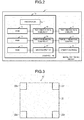
Fig. 2 is a block diagram illustrating an example of a configuration of theimage capturing device 1. As shown inFig. 2 , theimage capturing device 1 includes thecontroller 10, the two-dimensional camera 3, the three-dimensional camera 4 and theoperation panel 5. Thecontroller 10 is electrically connected to the two-dimensional camera 3, the three-dimensional camera 4 and theoperation panel 5. The two-dimensional camera 3, the three-dimensional camera 4 and theoperation panel 5 are as described above. - The
controller 10 includes aprocessor 11, a ROM (Read Only Memory) 12, a RAM (Random Access Memory) 13, an NVM (Non-Volatile Memory) 14, a two-dimensional camera interface 15, a three-dimensional camera interface 16 and an input/output interface 17. Theprocessor 11 is electrically connected to theROM 12, theRAM 13, theNVM 14, the two-dimensional camera interface 15, the three-dimensional camera interface 16 and the input/output interface 17. The two-dimensional camera interface 15 is electrically connected to the two-dimensional camera 3. The three-dimensional camera interface 16 is electrically connected to the three-dimensional camera 4. The input/output interface 17 is electrically connected to theoperation panel 5. - The
processor 11 controls the operation of theentire controller 10. Specifically, theprocessor 11 controls the operation of the entireimage capturing device 1. Theprocessor 11 may include an internal cache and various interfaces. Theprocessor 11 executes various kinds of processing by executing programs stored in the internal cache, theROM 12, or theNVM 14 in advance. - A part of various functions performed by the
processor 11 executing the programs may be performed by a hardware circuit. In this case, theprocessor 11 controls the functions performed by the hardware circuit. - The
ROM 12 is nonvolatile memory in which a control program, control data, and the like are stored in advance. The control program and the control data stored in theROM 12 are incorporated in advance according to a specification of thecontroller 10. TheROM 12 stores, for example, a program for controlling a circuit board of thecontroller 10. - The
RAM 13 is volatile memory. TheRAM 13 temporarily stores data being processed by theprocessor 11. TheRAM 13 stores various application programs based on an instruction from theprocessor 11. TheRAM 13 may store data necessary for executing the application program, an execution result of the application program, and the like. - The
NVM 14 is nonvolatile memory capable of writing and rewriting data. TheNVM 14 is, for example, an HDD (Hard Disk Drive), an SSD (Solid State Drive), an EEPROM® (Electrically Erasable Programmable Read-Only Memory), or a flash memory. TheNVM 14 stores a control program, applications, various kinds of data and the like according to an operation purpose of thecontroller 10. - The two-
dimensional camera interface 15 is used for transmitting and receiving data to and from the two-dimensional camera. For example, the two-dimensional camera interface 15 transmits a signal for instructing photographing to the two-dimensional camera 3 under the control of theprocessor 11. The two-dimensional camera interface 15 acquires information of a captured two-dimensional image from the two-dimensional camera 3. For example, the two-dimensional camera interface 15 may support a USB (Universal Serial Bus) connection. - The three-
dimensional camera interface 16 is used for transmitting and receiving data to and from the three-dimensional camera 4. For example, the three-dimensional camera interface 16 transmits a signal for instructing the three-dimensional camera 4 to acquire three-dimensional information under the control of theprocessor 11. The three-dimensional camera interface 16 acquires the three-dimensional information from the three-dimensional camera 4. For example, the three-dimensional camera interface 16 may support a USB connection. - The input/
output interface 17 is used for transmitting and receiving data to and from theoperation panel 5. For example, the input/output interface 17 receives a signal indicating the operation received from theoperation panel 5. The input/output interface 17 transmits information indicating a screen to be displayed to the operator to theoperation panel 5 under the control of theprocessor 11. For example, the input/output interface 17 may support USB connection. - The
image capturing device 1 may further include a component as required in addition to the components as shown inFig. 1 andFig. 2 , or may exclude a specific configuration therefrom. - Next, the
flat plate 20 is described. -
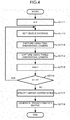
Fig. 3 is a diagram illustrating an example of a configuration of theflat plate 20. As shown inFig. 3 , theflat plate 20 has a rectangular shape. - The
flat plate 20 includes a first reflectingplate 21 and a second reflecting plate 22. The first reflectingplate 21 has a rectangular shape and has a predetermined size. The first reflectingplate 21 reflects the light emitted from the light source of the three-dimensional camera 4 at a predetermined reflectance (first reflectance). The first reflectingplate 21 is, for example, a metal plate. - The second reflecting plate 22 includes second reflecting
plates 22a to 22d. The second reflectingplates 22a to 22d each have a rectangular shape and have a predetermined size smaller than that of the first reflectingplate 21. The second reflectingplates 22a to 22d are disposed at four corners of the first reflectingplate 21, respectively. - The second reflecting
plates 22a to 22d reflect the light emitted from the light source of the three-dimensional camera 4 at a predetermined reflectance (second reflectance) different from that of the first reflectingplate 21. For example, the second reflectingplates 22a to 22d each are made of the material different from that of the first reflectingplate 21. - The second reflecting
plates 22a to 22d each may have a color different from that of the first reflectingplate 21. A predetermined code (for example, QR (Quick Response) code®) may be indicated on the second reflectingplates 22a to 22d. - Next, the function performed by the
processor 11 is described. Theprocessor 11 performs the following functions by executing programs stored in theROM 12 or theNVM 14. - First, the
processor 11 has a function of acquiring information of a two-dimensional image and three-dimensional information obtained by photographing theflat plate 20 by the two-dimensional camera 3 and the three-dimensional camera 4 respectively at a plurality of object distances. - The
processor 11 sets a distance (object distance) between the two-dimensional camera 3 or the three-dimensional camera 4 and theflat plate 20 as a first object distance. Specifically, theprocessor 11 places theflat plate 20 at a first position. The distance between theflat plate 20 and the two-dimensional camera 3 and the distance between the three-dimensional camera 4 and theflat plate 20 may be different from each other. Here, theprocessor 11 sets the two distances to predetermined distances. In other words, the object distance may include the two distances. - For example, the
processor 11 adjusts the height of the installation table 6 to a first height corresponding to the first object distance. For example, theprocessor 11 may drive the installation table 6 to fix it at the first height. Theprocessor 11 may display a message for prompting the operator to fix the installation table 6 at the first height on theoperation panel 5. - If the object distance is set to the first object distance, the
processor 11 photographs theflat plate 20 using the two-dimensional camera 3. Theprocessor 11 acquires information of a two-dimensional image (first two-dimensional image) obtained by photographing theflat plate 20 from the two-dimensional camera 3. - The
processor 11 photographs theflat plate 20 using the three-dimensional camera 4. Theprocessor 11 acquires three-dimensional information (first three-dimensional information) obtained by photographing theflat plate 20 from the three-dimensional camera 4. - The
processor 11 may acquire the information of the two-dimensional image and the three-dimensional information at the same time. Theprocessor 11 may acquire the information of the two-dimensional image and the three-dimensional information in a predetermined order. - If the information of the two-dimensional image and the three-dimensional information are acquired at the first object distance, the
processor 11 sets the object distance to the second object distance different from the first object distance. Specifically, theprocessor 11 places theflat plate 20 at a second position different from the first position. For example, theprocessor 11 adjusts the height of the installation table 6 to a second height corresponding to the second object distance. An example of the operation for adjusting the height of the installation table 6 by theprocessor 11 is as described above. If the object distance is set to the second object distance, theprocessor 11 photographs theflat plate 20 using the two-dimensional camera 3. Theprocessor 11 acquires information of a two-dimensional image (second two-dimensional image) obtained by photographing theflat plate 20 from the two-dimensional camera 3. - The
processor 11 photographs theflat plate 20 using the three-dimensional camera 4. Theprocessor 11 acquires three-dimensional information (second three-dimensional information) obtained by photographing theflat plate 20 from the three-dimensional camera 4. - The
processor 11 may acquire a two-dimensional image and three-dimensional information at a third object distance different from the first and second object distances. The number of object distances set by theprocessor 11 is not limited. - The
processor 11 has a function of specifying a point in the three-dimensional information corresponding to a point in the two-dimensional image. Specifically, theprocessor 11 specifies coordinates of a point in the same photographed area in the two-dimensional image and the three-dimensional information. - For example, the
processor 11 acquires the two-dimensional image and the three-dimensional information at a predetermined object distance. If the two-dimensional image and the three-dimensional information are acquired, theprocessor 11 acquires coordinates (two-dimensional vertex coordinates) of four vertices (two-dimensional vertices) of theflat plate 20, that is, four outer vertices of the second reflecting plates, from the two-dimensional image. - For example, the
processor 11 extracts edges of theflat plate 20 by extracting edges in the two-dimensional image. Theprocessor 11 specifies the four two-dimensional vertex coordinates of theflat plate 20 based on the extracted edges. - When the color of the first reflecting
plate 21 is different from that of the second reflecting plate 22, theprocessor 11 may specify the position of the color of the second reflecting plate 22 to specify four two-dimensional vertex coordinates. - When a code is formed on the second reflecting plate 22, the
processor 11 may specify the four two-dimensional vertex coordinates by reading the codes. - The method by which the
processor 11 specifies the two-dimensional vertex coordinates of theflat plate 20 is not limited to a specific method. - The
processor 11 specifies coordinates (three-dimensional vertex coordinates) of the four vertices (three-dimensional vertices) of theflat plate 20 in the three-dimensional information. - As described above, the
flat plate 20 has the second reflecting plate 22 having reflectance different from that of the first reflectingplate 21 at the four corners. Because of the difference in reflectance, the three-dimensional camera 4 can detect the second reflecting plate 22 in a different plane from the first reflectingplate 21. Specifically, the three-dimensional camera 4 recognizes an area of the second reflecting plate 22 closer to or farther from that of the first reflectingplate 21. - The
processor 11 specifies an area closer to or farther from the first reflectingplate 21 as the area of the second reflecting plate 22. Theprocessor 11 specifies three-dimensional vertex coordinates based on the position of the area of the second reflecting plate 22. - The
processor 11 may specify three-dimensional vertex coordinates by creating a binary image using a distance (density) slightly above the installation table 6 as a threshold value in the three-dimensional information and acquiring a contour line of theflat plate 20. Theprocessor 11 may specify the three-dimensional vertex coordinates by detecting a plane from a point group constituted by points in the three-dimensional information. - The method by which the
processor 11 specifies the three-dimensional vertex coordinates of theflat plate 20 is not limited to a specific method. - The
processor 11 specifies four three-dimensional vertex coordinates as points corresponding to the four two-dimensional vertex coordinates. - For example, the
processor 11 specifies the two-dimensional vertex coordinates (first two-dimensional coordinates) of the four two-dimensional vertices and the three-dimensional vertex coordinates of the four three-dimensional vertices (first three-dimensional coordinates) at the first object distance. Specifically, the processor specifies four three-dimensional vertex coordinates (first three-dimensional coordinates) corresponding to four two-dimensional vertex coordinates (first two-dimensional coordinates) at the first object distance. - For example, the
processor 11 specifies the two-dimensional vertex coordinates (second two-dimensional coordinates) of the four two-dimensional vertices and the three-dimensional vertex coordinates of the four three-dimensional vertices (second three-dimensional coordinates) at the second object distance. Specifically, the processor specifies four three-dimensional vertex coordinates (second three-dimensional coordinates) corresponding to four two-dimensional vertex coordinates (second two-dimensional coordinates) at the second object distance. - The
processor 11 has a function of generating a transformation matrix for transforming the three-dimensional coordinates in the three-dimensional information to the two-dimensional coordinates in the two-dimensional image based on the associated two-dimensional vertex coordinates and three-dimensional vertex coordinates at each object distance. - Specifically, the
processor 11 calculates a value of an element of the transformation matrix. - For example, the transformation matrix is a projective transformation matrix. The transformation matrix may be an affine transformation matrix.
- The
processor 11 calculates a transformation matrix from the associated four two-dimensional vertex coordinates and four three-dimensional vertex coordinates (sets) at each object distance. - For example, the
processor 11 calculates a transformation matrix at the first object distance from the four two-dimensional vertex coordinates and the four three-dimensional vertex coordinates at the first object distance. Theprocessor 11 similarly calculates a transformation matrix at the second object distance. - The
processor 11 estimates a transformation matrix at any object distance based on the transformation matrix at the first object distance and the transformation matrix at the second object distance. For example, theprocessor 11 linearly estimates the value of each element of the transformation matrix at the object distance at any object distance. When there are three or more sets, theprocessor 11 calculates a transformation matrix at three or more object distances. Theprocessor 11 estimates the transformation matrix at any object distance from the transformation matrix at three or more object distances. Theprocessor 11 may linearly estimate the value of each element of the transformation matrix at any object distance. Theprocessor 11 may estimate the value of each element of the transformation matrix at any object distance using an n-th power approximate expression. - Next, an example of a calibration operation performed by the
processor 11 is described. -
Fig. 4 is a flowchart depicting an example of a calibration operation performed by theprocessor 11. Here, it is assumed that theprocessor 11 receives an input of an operation for instructing execution of the calibration via theoperation panel 5. - First, the
processor 11 resets n (ACT 11). Specifically, theprocessor 11 sets n = 0. Here, n is the number of sets composed of the two-dimensional image and the three-dimensional information acquired by theprocessor 11. - If n is reset, the
processor 11 sets a predetermined object distance (e.g., the first or second object distance) (ACT 12). If the predetermined object distance is set, theprocessor 11 acquires information of a two-dimensional image including theflat plate 20 from the two-dimensional camera 3 (ACT 13). - If the information of the two-dimensional image including the
flat plate 20 is acquired, theprocessor 11 acquires three-dimensional information including theflat plate 20 from the three-dimensional camera 4 (ACT 14). - If the three-dimensional information including the
flat plate 20 is acquired, theprocessor 11 increments n by 1 (ACT 15). If n is incremented by 1, theprocessor 11 determines whether m > n (ACT 16). Here, m is the number of object distances set for acquiring the two-dimensional image and the three-dimensional information. - If it is determined that m > n is not satisfied (No in ACT 16), the process returns to
ACT 12. - If it is determined that m > n (Yes in ACT 16), the
processor 11 specifies four two-dimensional vertex coordinates and four three-dimensional vertex coordinates at each object distance (ACT 17). If the four two-dimensional vertex coordinates and four three-dimensional vertex coordinates at each object distance are specified, theprocessor 11 generates a transformation matrix based on the specified two-dimensional vertex coordinates and three-dimensional vertex coordinates (ACT 18). - If the transformation matrix is generated, the
processor 11 terminates the above operation. - The
processor 11 may execute the processing inACT 13 afterACT 14. Theprocessor 11 may simultaneously execute the processing inACT 13 andACT 14. Theprocessor 11 may specify the four two-dimensional vertex coordinates and four three-dimensional vertex coordinates afterACT 14. - The
flat plate 20 may have a circular shape, an oval shape, a rectangular shape, a parallelogram shape, or a polygonal shape. The shape of theflat plate 20 is not limited to a specific shape. - The second reflecting plate 22 may have a circular shape, an oval shape, a rectangular shape, a parallelogram shape, or a polygonal shape. The shape of the second reflecting plate 22 is not limited to a specific shape.
- The
flat plate 20 may not have the second reflecting plate 22. - The image capturing device configured as described above acquires information of two-dimensional images and three-dimensional information by setting a plurality of object distances. The image capturing device specifies the two-dimensional vertex coordinates and the three-dimensional vertex coordinates from the information of the two-dimensional image and the three-dimensional information at each object distance. The image capturing device generates a transformation matrix (e.g., Affine transformation matrix or homography transformation matrix) for transforming the three-dimensional coordinates in the three-dimensional information to the two-dimensional coordinates in the two-dimensional image based on the specified two-dimensional vertex coordinates and three-dimensional vertex coordinates. As a result, the image capturing device can effectively perform calibration. Further, it is possible to determine a relationship between a three-dimensional image and a two-dimensional image using the transformation matrix, when characteristics of a camera to capture the three-dimensional image or the two-dimensional image are unknown.
- The image capturing device can acquire information of two-dimensional images and three-dimensional information at different object distances without using a three-dimensional object as an object to be captured. As a result, the image capturing device can easily perform calibration.
- While certain embodiments have been described, these embodiments have been presented by way of example only, and are not intended to limit the scope of the invention. Indeed, the novel embodiments described herein may be embodied in a variety of other forms; furthermore, various omissions, substitutions and changes in the form of the embodiments described herein may be made without departing from the scope of the invention. The accompanying claims and their equivalents are intended to cover such forms or modifications as would fall within the scope of the invention.
Claims (15)
- An information processing apparatus that performs coordinate calibration between a two-dimensional (2D) coordinate system and a three-dimensional (3D) coordinate system, said apparatus comprising:a 2D camera interface connectable to a 2D camera;a 3D camera interface connectable to a 3D camera; anda processor configured to:receive, from the 2D camera interface, first 2D image data of a flat plate at a first position and second 2D image data of the flat plate at a second position different from the first position;receive, from the 3D camera interface, first 3D coordinate information of the flat plate at the first position and second 3D coordinate information of the flat plate at the second position; andgenerate a transformation matrix for transforming a 3D coordinate value of a point in a 3D coordinate system to a 2D coordinate value of the point in a 2D coordinate system, based on the first and second 2D image data and the first and second 3D coordinate information.
- The information processing apparatus according to claim 1, wherein
the processor is configured to:specify, from the first 3D coordinate information, four first 3D coordinate values corresponding to four first 2D coordinate values in the first 2D image data,specify, from the second 3D coordinate information, four second 3D coordinate values corresponding to four second 2D coordinate values in the second 2D image data; andgenerate the transformation matrix based on the four first 2D coordinate values, the four first 3D coordinate values, the four second 2D coordinate values, and the four second 3D coordinate values. - The information processing apparatus according to claim 2, whereinthe flat plate has a rectangular shape, andthe four first 2D coordinate values and the four second 2D coordinate values are coordinate values of four vertexes of the flat plate.
- The information processing apparatus according to any one of claims 1 to 3, wherein
the flat plate includes a first reflecting plate having a first reflectance, and four second reflecting plates at four corners of the first reflecting plate, each of the four second reflecting plates having a second reflectance different from the first reflectance. - The information processing apparatus according to claim 4, whereinthe 3D camera measures a distance to the flat plate by acquiring light emitted from a predetermined light source and reflected by the first reflecting plate or one of the four second reflecting plates, andthe processor specifies, as the four first 3D coordinate values, four positions of the four second reflecting plates based on the first 3D coordinate information.
- The information processing apparatus according to any one of claims 1 to 5, further comprising:the 2D camera;the 3D camera; andthe flat plate.
- The information processing apparatus according to any one of claims 1 to 6, further comprising:a driving mechanism configured to move the flat plate in a direction closer to or apart from the 2D camera and the 3D camera, whereinthe processor is further configured to control the driving mechanism to move the flat plate to the first position and to the second position.
- The information processing apparatus according to any one of claims 1 to 7, wherein
the processor is configured to:generate a first transformation matrix for transforming a 3D coordinate value of a point in a 3D coordinate system to a 2D coordinate value of the point in a 2D coordinate system corresponding to a surface of the flat plate at the first position;generate a second transformation matrix for transforming a 3D coordinate value of a point in a 3D coordinate system to a 2D coordinate value of the point in a 2D coordinate system corresponding to the surface of the flat plate at the second position; andgenerate a third transformation matrix for transforming a 3D coordinate value of a point in a 3D coordinate system to a 2D coordinate value of the point in a 2D coordinate system corresponding to the surface of the flat plate at a third position different from the first and second positions, based on the first transformation matrix and the second transformation matrix. - The information processing apparatus according to claim 8, wherein
the processor generates the third transformation matrix based on a linear approximation of the first and second transformation matrices. - The information processing apparatus according to claim 8, wherein
the processor generates the third transformation matrix based on an n-th power approximation of the first and second transformation matrices. - A coordinate calibration method comprising:obtaining first 2D image data by two-dimensionally photographing a flat plate at a first position;obtaining first 3D coordinate information by three-dimensionally photographing the flat plate at the first position;obtaining second 2D image data by two-dimensionally photographing the flat plate at a second position different from the first position;obtaining second 3D coordinate information by three-dimensionally photographing the flat plate at the second position; andgenerating a transformation matrix for transforming a 3D coordinate value of a point in a 3D coordinate system to a 2D coordinate value of the point in a 2D coordinate system, based on the first and second 2D image data and the first and second 3D coordinate information.
- The coordinate calibration method according to claim 11, further comprising:specifying, from the first 3D coordinate information, four first 3D coordinate values corresponding to four first 2D coordinate values in the first 2D image data; andspecifying, from the second 3D coordinate information, four second 3D coordinate values corresponding to four second 2D coordinate values in the second 2D image data, whereinthe transformation matrix is generated based on the four first 2D coordinate values, the four first 3D coordinate values, the four second 2D coordinate values, and the four second 3D coordinate values.
- The coordinate calibration method according to claim 12, whereinthe flat plate has a rectangular shape, andthe four first 2D coordinate values and the four second 2D coordinate values are coordinate values of four vertexes of the flat plate.
- The coordinate calibration method according to any one of claims 11 to 13, wherein
the flat plate includes a first reflecting plate having a first reflectance, and four second reflecting plates at four corners of the first reflecting plate, each of the four second reflecting plates having a second reflectance different from the first reflectance. - A non-transitory computer readable medium storing a program causing a computer to execute the method according to any one of claims 11 to 14.
Applications Claiming Priority (1)
| Application Number | Priority Date | Filing Date | Title |
|---|---|---|---|
| JP2018042245A JP2019158414A (en) | 2018-03-08 | 2018-03-08 | Information processing device |
Publications (2)
| Publication Number | Publication Date |
|---|---|
| EP3537380A1 true EP3537380A1 (en) | 2019-09-11 |
| EP3537380B1 EP3537380B1 (en) | 2022-11-16 |
Family
ID=65729171
Family Applications (1)
| Application Number | Title | Priority Date | Filing Date |
|---|---|---|---|
| EP19161534.3A Active EP3537380B1 (en) | 2018-03-08 | 2019-03-08 | Coordinate calibration between two-dimensional coordinate system and three-dimensional coordinate system |
Country Status (3)
| Country | Link |
|---|---|
| US (1) | US10896521B2 (en) |
| EP (1) | EP3537380B1 (en) |
| JP (1) | JP2019158414A (en) |
Cited By (1)
| Publication number | Priority date | Publication date | Assignee | Title |
|---|---|---|---|---|
| CN114170302A (en) * | 2020-08-20 | 2022-03-11 | 北京达佳互联信息技术有限公司 | Camera external parameter calibration method, device, electronic device and storage medium |
Families Citing this family (11)
| Publication number | Priority date | Publication date | Assignee | Title |
|---|---|---|---|---|
| US11049282B2 (en) * | 2019-02-28 | 2021-06-29 | Intelligrated Headquarters, Llc | Vision calibration system for robotic carton unloading |
| WO2021131950A1 (en) * | 2019-12-26 | 2021-07-01 | ソニーグループ株式会社 | Information processing device, information processing method, and program |
| CN111879842B (en) * | 2020-07-15 | 2023-10-17 | 宁波大学 | Coordinate mapping methods in different dimensional spaces and single cell mass spectrometry detection methods |
| CN111862242B (en) * | 2020-07-29 | 2023-11-03 | 北京轻威科技有限责任公司 | Calibration system and method for optical-inertial hybrid motion capture equipment |
| CN113379846B (en) * | 2021-05-28 | 2022-08-09 | 上海汇像信息技术有限公司 | Method for calibrating rotating shaft of rotary table based on direction indication mark point calibration template |
| CN115511771A (en) * | 2021-06-07 | 2022-12-23 | 泰科电子(上海)有限公司 | Method and system for inspecting three-dimensional objects |
| US12307690B2 (en) | 2021-08-19 | 2025-05-20 | Industrial Technology Research Institute | Multi-modal image alignment method and system |
| TWI790854B (en) * | 2021-08-19 | 2023-01-21 | 財團法人工業技術研究院 | Multi-modal image alignment method and system |
| JP7228070B1 (en) * | 2022-07-20 | 2023-02-22 | 株式会社ダイヘン | Point cloud data synthesizing device, point cloud data synthesizing program, point cloud data synthesizing method, and point cloud data synthesizing system |
| WO2024053876A1 (en) * | 2022-09-08 | 2024-03-14 | 삼성전자 주식회사 | Electronic device performing camera calibration, and operation method therefor |
| CN118470136B (en) * | 2024-07-08 | 2024-11-26 | 阿里云计算有限公司 | Camera calibration method, device and system, image acquisition method and device |
Citations (2)
| Publication number | Priority date | Publication date | Assignee | Title |
|---|---|---|---|---|
| US6101455A (en) * | 1998-05-14 | 2000-08-08 | Davis; Michael S. | Automatic calibration of cameras and structured light sources |
| US20160245899A1 (en) * | 2016-04-29 | 2016-08-25 | Caterpillar Inc. | Sensor calibration system |
Family Cites Families (10)
| Publication number | Priority date | Publication date | Assignee | Title |
|---|---|---|---|---|
| US11699247B2 (en) * | 2009-12-24 | 2023-07-11 | Cognex Corporation | System and method for runtime determination of camera miscalibration |
| US8676498B2 (en) * | 2010-09-24 | 2014-03-18 | Honeywell International Inc. | Camera and inertial measurement unit integration with navigation data feedback for feature tracking |
| US8836768B1 (en) * | 2012-09-04 | 2014-09-16 | Aquifi, Inc. | Method and system enabling natural user interface gestures with user wearable glasses |
| JP2014163833A (en) | 2013-02-26 | 2014-09-08 | Optex Co Ltd | Dimension measurement system, and dimension measurement method |
| JP6721884B2 (en) * | 2015-09-29 | 2020-07-15 | 日本電気株式会社 | Camera calibration board, camera calibration device, camera calibration method, and camera calibration program recording medium |
| CA2961921C (en) * | 2016-03-29 | 2020-05-12 | Institut National D'optique | Camera calibration method using a calibration target |
| DE112018002048T5 (en) * | 2017-04-17 | 2020-02-20 | Cognex Corp. | HIGHLY ACCURATE CALIBRATION SYSTEM AND CALIBRATION PROCESS |
| WO2019079211A1 (en) * | 2017-10-19 | 2019-04-25 | DeepMap Inc. | Lidar to camera calibration for generating high definition maps |
| CN109754426B (en) * | 2017-11-01 | 2021-04-23 | 虹软科技股份有限公司 | Method, system and device for verifying camera calibration parameters |
| US11259000B2 (en) * | 2018-07-02 | 2022-02-22 | Lumierev Inc. | Spatiotemporal calibration of RGB-D and displacement sensors |
-
2018
- 2018-03-08 JP JP2018042245A patent/JP2019158414A/en active Pending
-
2019
- 2019-03-01 US US16/290,290 patent/US10896521B2/en not_active Expired - Fee Related
- 2019-03-08 EP EP19161534.3A patent/EP3537380B1/en active Active
Patent Citations (2)
| Publication number | Priority date | Publication date | Assignee | Title |
|---|---|---|---|---|
| US6101455A (en) * | 1998-05-14 | 2000-08-08 | Davis; Michael S. | Automatic calibration of cameras and structured light sources |
| US20160245899A1 (en) * | 2016-04-29 | 2016-08-25 | Caterpillar Inc. | Sensor calibration system |
Non-Patent Citations (4)
| Title |
|---|
| GARCÍA-MORENO ANGEL-IVÁN ET AL: "LIDAR and Panoramic Camera Extrinsic Calibration Approach Using a Pattern Plane", 26 June 2013, IMAGE ANALYSIS AND RECOGNITION : 11TH INTERNATIONAL CONFERENCE, ICIAR 2014, VILAMOURA, PORTUGAL, OCTOBER 22-24, 2014, PROCEEDINGS, PART I; IN: LECTURE NOTES IN COMPUTER SCIENCE , ISSN 1611-3349 ; VOL. 8814; [LECTURE NOTES IN COMPUTER SCIENCE; LECT.NO, ISBN: 978-3-642-17318-9, XP047470411 * |
| JIYOUNG JUNG ET AL: "A novel 2.5D pattern for extrinsic calibration of ToF and camera fusion system", INTELLIGENT ROBOTS AND SYSTEMS (IROS), 2011 IEEE/RSJ INTERNATIONAL CONFERENCE ON, IEEE, 25 September 2011 (2011-09-25), pages 3290 - 3296, XP032060856, ISBN: 978-1-61284-454-1, DOI: 10.1109/IROS.2011.6048877 * |
| WEIMIN WANG ET AL: "Reflectance Intensity Assisted Automatic and Accurate Extrinsic Calibration of 3D LiDAR and Panoramic Camera Using a Printed Chessboard", ARXIV.ORG, CORNELL UNIVERSITY LIBRARY, 201 OLIN LIBRARY CORNELL UNIVERSITY ITHACA, NY 14853, 18 August 2017 (2017-08-18), XP080953421, DOI: 10.3390/RS9080851 * |
| YOONSU PARK ET AL: "Calibration between Color Camera and 3D LIDAR Instruments with a Polygonal Planar Board", SENSORS, vol. 14, no. 3, 17 March 2014 (2014-03-17), pages 5333 - 5353, XP055209758, ISSN: 1424-8220, DOI: 10.3390/s140305333 * |
Cited By (1)
| Publication number | Priority date | Publication date | Assignee | Title |
|---|---|---|---|---|
| CN114170302A (en) * | 2020-08-20 | 2022-03-11 | 北京达佳互联信息技术有限公司 | Camera external parameter calibration method, device, electronic device and storage medium |
Also Published As
| Publication number | Publication date |
|---|---|
| JP2019158414A (en) | 2019-09-19 |
| US20190279399A1 (en) | 2019-09-12 |
| US10896521B2 (en) | 2021-01-19 |
| EP3537380B1 (en) | 2022-11-16 |
Similar Documents
| Publication | Publication Date | Title |
|---|---|---|
| US10896521B2 (en) | Coordinate calibration between two dimensional coordinate system and three dimensional coordinate system | |
| CN110570477B (en) | Method, device and storage medium for calibrating relative attitude of camera and rotating shaft | |
| CN113034612B (en) | Calibration device, method and depth camera | |
| JP7300948B2 (en) | Survey data processing device, survey data processing method, program for survey data processing | |
| EP3258210B1 (en) | Automatic mode switching in a system for measuring dimensions | |
| US11727585B2 (en) | Information processing device, information processing method, and program | |
| US12026916B2 (en) | Method and apparatus for in-field stereo calibration | |
| JP2012058076A (en) | Three-dimensional measurement device and three-dimensional measurement method | |
| KR102618285B1 (en) | Method and system for determining camera pose | |
| JP2016100698A (en) | Calibration device, calibration method, program | |
| JP7489670B2 (en) | Correction parameter calculation method, displacement amount calculation method, correction parameter calculation device, and displacement amount calculation device | |
| CN109855568A (en) | Method and device for detecting automatic driving sensor, electronic equipment and storage medium | |
| KR20180121259A (en) | Distance detecting device of camera mounted computer and its method | |
| KR101523046B1 (en) | Distance measurement apparatus of an image processing-based | |
| CN114502913A (en) | Correction parameter calculation method and device, and displacement calculation method and device | |
| JP2016085380A (en) | Controller, control method, and program | |
| JP6921036B2 (en) | A laser calibrator, a method for calibrating the laser, and an image input device including the laser calibrator. | |
| WO2015159835A1 (en) | Image processing device, image processing method, and program | |
| KR101165340B1 (en) | Projector calibration system using camera and method using this | |
| US20200217661A1 (en) | Queue of data collection tasks for surveying instrument | |
| JP2016224016A (en) | Three-dimensional position measurement method, surveying method, surface specification method, three-dimensional position measurement apparatus, and three-dimensional position measurement program | |
| JP7020074B2 (en) | Surface property acquisition device, surface property acquisition system and program | |
| US11328438B2 (en) | Image processing system and image processing method | |
| JP7653317B2 (en) | Information processing device | |
| JP7664777B2 (en) | Position detection marker and information processing system |
Legal Events
| Date | Code | Title | Description |
|---|---|---|---|
| PUAI | Public reference made under article 153(3) epc to a published international application that has entered the european phase |
Free format text: ORIGINAL CODE: 0009012 |
|
| STAA | Information on the status of an ep patent application or granted ep patent |
Free format text: STATUS: THE APPLICATION HAS BEEN PUBLISHED |
|
| AK | Designated contracting states |
Kind code of ref document: A1 Designated state(s): AL AT BE BG CH CY CZ DE DK EE ES FI FR GB GR HR HU IE IS IT LI LT LU LV MC MK MT NL NO PL PT RO RS SE SI SK SM TR |
|
| AX | Request for extension of the european patent |
Extension state: BA ME |
|
| STAA | Information on the status of an ep patent application or granted ep patent |
Free format text: STATUS: REQUEST FOR EXAMINATION WAS MADE |
|
| 17P | Request for examination filed |
Effective date: 20200311 |
|
| RBV | Designated contracting states (corrected) |
Designated state(s): AL AT BE BG CH CY CZ DE DK EE ES FI FR GB GR HR HU IE IS IT LI LT LU LV MC MK MT NL NO PL PT RO RS SE SI SK SM TR |
|
| STAA | Information on the status of an ep patent application or granted ep patent |
Free format text: STATUS: EXAMINATION IS IN PROGRESS |
|
| 17Q | First examination report despatched |
Effective date: 20200526 |
|
| GRAP | Despatch of communication of intention to grant a patent |
Free format text: ORIGINAL CODE: EPIDOSNIGR1 |
|
| STAA | Information on the status of an ep patent application or granted ep patent |
Free format text: STATUS: GRANT OF PATENT IS INTENDED |
|
| INTG | Intention to grant announced |
Effective date: 20220603 |
|
| GRAS | Grant fee paid |
Free format text: ORIGINAL CODE: EPIDOSNIGR3 |
|
| GRAA | (expected) grant |
Free format text: ORIGINAL CODE: 0009210 |
|
| STAA | Information on the status of an ep patent application or granted ep patent |
Free format text: STATUS: THE PATENT HAS BEEN GRANTED |
|
| AK | Designated contracting states |
Kind code of ref document: B1 Designated state(s): AL AT BE BG CH CY CZ DE DK EE ES FI FR GB GR HR HU IE IS IT LI LT LU LV MC MK MT NL NO PL PT RO RS SE SI SK SM TR |
|
| REG | Reference to a national code |
Ref country code: GB Ref legal event code: FG4D |
|
| REG | Reference to a national code |
Ref country code: CH Ref legal event code: EP |
|
| REG | Reference to a national code |
Ref country code: IE Ref legal event code: FG4D |
|
| REG | Reference to a national code |
Ref country code: DE Ref legal event code: R096 Ref document number: 602019021874 Country of ref document: DE |
|
| REG | Reference to a national code |
Ref country code: AT Ref legal event code: REF Ref document number: 1532234 Country of ref document: AT Kind code of ref document: T Effective date: 20221215 |
|
| REG | Reference to a national code |
Ref country code: LT Ref legal event code: MG9D |
|
| REG | Reference to a national code |
Ref country code: NL Ref legal event code: MP Effective date: 20221116 |
|
| REG | Reference to a national code |
Ref country code: AT Ref legal event code: MK05 Ref document number: 1532234 Country of ref document: AT Kind code of ref document: T Effective date: 20221116 |
|
| PG25 | Lapsed in a contracting state [announced via postgrant information from national office to epo] |
Ref country code: SE Free format text: LAPSE BECAUSE OF FAILURE TO SUBMIT A TRANSLATION OF THE DESCRIPTION OR TO PAY THE FEE WITHIN THE PRESCRIBED TIME-LIMIT Effective date: 20221116 Ref country code: PT Free format text: LAPSE BECAUSE OF FAILURE TO SUBMIT A TRANSLATION OF THE DESCRIPTION OR TO PAY THE FEE WITHIN THE PRESCRIBED TIME-LIMIT Effective date: 20230316 Ref country code: NO Free format text: LAPSE BECAUSE OF FAILURE TO SUBMIT A TRANSLATION OF THE DESCRIPTION OR TO PAY THE FEE WITHIN THE PRESCRIBED TIME-LIMIT Effective date: 20230216 Ref country code: LT Free format text: LAPSE BECAUSE OF FAILURE TO SUBMIT A TRANSLATION OF THE DESCRIPTION OR TO PAY THE FEE WITHIN THE PRESCRIBED TIME-LIMIT Effective date: 20221116 Ref country code: FI Free format text: LAPSE BECAUSE OF FAILURE TO SUBMIT A TRANSLATION OF THE DESCRIPTION OR TO PAY THE FEE WITHIN THE PRESCRIBED TIME-LIMIT Effective date: 20221116 Ref country code: ES Free format text: LAPSE BECAUSE OF FAILURE TO SUBMIT A TRANSLATION OF THE DESCRIPTION OR TO PAY THE FEE WITHIN THE PRESCRIBED TIME-LIMIT Effective date: 20221116 Ref country code: AT Free format text: LAPSE BECAUSE OF FAILURE TO SUBMIT A TRANSLATION OF THE DESCRIPTION OR TO PAY THE FEE WITHIN THE PRESCRIBED TIME-LIMIT Effective date: 20221116 |
|
| PG25 | Lapsed in a contracting state [announced via postgrant information from national office to epo] |
Ref country code: RS Free format text: LAPSE BECAUSE OF FAILURE TO SUBMIT A TRANSLATION OF THE DESCRIPTION OR TO PAY THE FEE WITHIN THE PRESCRIBED TIME-LIMIT Effective date: 20221116 Ref country code: PL Free format text: LAPSE BECAUSE OF FAILURE TO SUBMIT A TRANSLATION OF THE DESCRIPTION OR TO PAY THE FEE WITHIN THE PRESCRIBED TIME-LIMIT Effective date: 20221116 Ref country code: LV Free format text: LAPSE BECAUSE OF FAILURE TO SUBMIT A TRANSLATION OF THE DESCRIPTION OR TO PAY THE FEE WITHIN THE PRESCRIBED TIME-LIMIT Effective date: 20221116 Ref country code: IS Free format text: LAPSE BECAUSE OF FAILURE TO SUBMIT A TRANSLATION OF THE DESCRIPTION OR TO PAY THE FEE WITHIN THE PRESCRIBED TIME-LIMIT Effective date: 20230316 Ref country code: HR Free format text: LAPSE BECAUSE OF FAILURE TO SUBMIT A TRANSLATION OF THE DESCRIPTION OR TO PAY THE FEE WITHIN THE PRESCRIBED TIME-LIMIT Effective date: 20221116 Ref country code: GR Free format text: LAPSE BECAUSE OF FAILURE TO SUBMIT A TRANSLATION OF THE DESCRIPTION OR TO PAY THE FEE WITHIN THE PRESCRIBED TIME-LIMIT Effective date: 20230217 |
|
| PG25 | Lapsed in a contracting state [announced via postgrant information from national office to epo] |
Ref country code: NL Free format text: LAPSE BECAUSE OF FAILURE TO SUBMIT A TRANSLATION OF THE DESCRIPTION OR TO PAY THE FEE WITHIN THE PRESCRIBED TIME-LIMIT Effective date: 20221116 |
|
| PG25 | Lapsed in a contracting state [announced via postgrant information from national office to epo] |
Ref country code: SM Free format text: LAPSE BECAUSE OF FAILURE TO SUBMIT A TRANSLATION OF THE DESCRIPTION OR TO PAY THE FEE WITHIN THE PRESCRIBED TIME-LIMIT Effective date: 20221116 Ref country code: RO Free format text: LAPSE BECAUSE OF FAILURE TO SUBMIT A TRANSLATION OF THE DESCRIPTION OR TO PAY THE FEE WITHIN THE PRESCRIBED TIME-LIMIT Effective date: 20221116 Ref country code: EE Free format text: LAPSE BECAUSE OF FAILURE TO SUBMIT A TRANSLATION OF THE DESCRIPTION OR TO PAY THE FEE WITHIN THE PRESCRIBED TIME-LIMIT Effective date: 20221116 Ref country code: DK Free format text: LAPSE BECAUSE OF FAILURE TO SUBMIT A TRANSLATION OF THE DESCRIPTION OR TO PAY THE FEE WITHIN THE PRESCRIBED TIME-LIMIT Effective date: 20221116 Ref country code: CZ Free format text: LAPSE BECAUSE OF FAILURE TO SUBMIT A TRANSLATION OF THE DESCRIPTION OR TO PAY THE FEE WITHIN THE PRESCRIBED TIME-LIMIT Effective date: 20221116 |
|
| REG | Reference to a national code |
Ref country code: DE Ref legal event code: R097 Ref document number: 602019021874 Country of ref document: DE |
|
| PG25 | Lapsed in a contracting state [announced via postgrant information from national office to epo] |
Ref country code: SK Free format text: LAPSE BECAUSE OF FAILURE TO SUBMIT A TRANSLATION OF THE DESCRIPTION OR TO PAY THE FEE WITHIN THE PRESCRIBED TIME-LIMIT Effective date: 20221116 Ref country code: AL Free format text: LAPSE BECAUSE OF FAILURE TO SUBMIT A TRANSLATION OF THE DESCRIPTION OR TO PAY THE FEE WITHIN THE PRESCRIBED TIME-LIMIT Effective date: 20221116 |
|
| PLBE | No opposition filed within time limit |
Free format text: ORIGINAL CODE: 0009261 |
|
| STAA | Information on the status of an ep patent application or granted ep patent |
Free format text: STATUS: NO OPPOSITION FILED WITHIN TIME LIMIT |
|
| 26N | No opposition filed |
Effective date: 20230817 |
|
| PG25 | Lapsed in a contracting state [announced via postgrant information from national office to epo] |
Ref country code: MC Free format text: LAPSE BECAUSE OF FAILURE TO SUBMIT A TRANSLATION OF THE DESCRIPTION OR TO PAY THE FEE WITHIN THE PRESCRIBED TIME-LIMIT Effective date: 20221116 |
|
| REG | Reference to a national code |
Ref country code: CH Ref legal event code: PL |
|
| PG25 | Lapsed in a contracting state [announced via postgrant information from national office to epo] |
Ref country code: SI Free format text: LAPSE BECAUSE OF FAILURE TO SUBMIT A TRANSLATION OF THE DESCRIPTION OR TO PAY THE FEE WITHIN THE PRESCRIBED TIME-LIMIT Effective date: 20221116 |
|
| REG | Reference to a national code |
Ref country code: BE Ref legal event code: MM Effective date: 20230331 |
|
| PG25 | Lapsed in a contracting state [announced via postgrant information from national office to epo] |
Ref country code: LU Free format text: LAPSE BECAUSE OF NON-PAYMENT OF DUE FEES Effective date: 20230308 |
|
| REG | Reference to a national code |
Ref country code: IE Ref legal event code: MM4A |
|
| PG25 | Lapsed in a contracting state [announced via postgrant information from national office to epo] |
Ref country code: LI Free format text: LAPSE BECAUSE OF NON-PAYMENT OF DUE FEES Effective date: 20230331 Ref country code: IE Free format text: LAPSE BECAUSE OF NON-PAYMENT OF DUE FEES Effective date: 20230308 Ref country code: CH Free format text: LAPSE BECAUSE OF NON-PAYMENT OF DUE FEES Effective date: 20230331 |
|
| PGFP | Annual fee paid to national office [announced via postgrant information from national office to epo] |
Ref country code: FR Payment date: 20231229 Year of fee payment: 6 |
|
| PG25 | Lapsed in a contracting state [announced via postgrant information from national office to epo] |
Ref country code: BE Free format text: LAPSE BECAUSE OF NON-PAYMENT OF DUE FEES Effective date: 20230331 |
|
| PGFP | Annual fee paid to national office [announced via postgrant information from national office to epo] |
Ref country code: DE Payment date: 20231229 Year of fee payment: 6 Ref country code: GB Payment date: 20240108 Year of fee payment: 6 |
|
| PG25 | Lapsed in a contracting state [announced via postgrant information from national office to epo] |
Ref country code: IT Free format text: LAPSE BECAUSE OF FAILURE TO SUBMIT A TRANSLATION OF THE DESCRIPTION OR TO PAY THE FEE WITHIN THE PRESCRIBED TIME-LIMIT Effective date: 20221116 |
|
| PG25 | Lapsed in a contracting state [announced via postgrant information from national office to epo] |
Ref country code: BG Free format text: LAPSE BECAUSE OF FAILURE TO SUBMIT A TRANSLATION OF THE DESCRIPTION OR TO PAY THE FEE WITHIN THE PRESCRIBED TIME-LIMIT Effective date: 20221116 |
|
| PG25 | Lapsed in a contracting state [announced via postgrant information from national office to epo] |
Ref country code: BG Free format text: LAPSE BECAUSE OF FAILURE TO SUBMIT A TRANSLATION OF THE DESCRIPTION OR TO PAY THE FEE WITHIN THE PRESCRIBED TIME-LIMIT Effective date: 20221116 |
|
| PG25 | Lapsed in a contracting state [announced via postgrant information from national office to epo] |
Ref country code: CY Free format text: LAPSE BECAUSE OF FAILURE TO SUBMIT A TRANSLATION OF THE DESCRIPTION OR TO PAY THE FEE WITHIN THE PRESCRIBED TIME-LIMIT; INVALID AB INITIO Effective date: 20190308 |
|
| PG25 | Lapsed in a contracting state [announced via postgrant information from national office to epo] |
Ref country code: HU Free format text: LAPSE BECAUSE OF FAILURE TO SUBMIT A TRANSLATION OF THE DESCRIPTION OR TO PAY THE FEE WITHIN THE PRESCRIBED TIME-LIMIT; INVALID AB INITIO Effective date: 20190308 |
|
| REG | Reference to a national code |
Ref country code: DE Ref legal event code: R119 Ref document number: 602019021874 Country of ref document: DE |
|
| GBPC | Gb: european patent ceased through non-payment of renewal fee |
Effective date: 20250308 |
|
| PG25 | Lapsed in a contracting state [announced via postgrant information from national office to epo] |
Ref country code: TR Free format text: LAPSE BECAUSE OF FAILURE TO SUBMIT A TRANSLATION OF THE DESCRIPTION OR TO PAY THE FEE WITHIN THE PRESCRIBED TIME-LIMIT Effective date: 20221116 |
|
| PG25 | Lapsed in a contracting state [announced via postgrant information from national office to epo] |
Ref country code: DE Free format text: LAPSE BECAUSE OF NON-PAYMENT OF DUE FEES Effective date: 20251001 |
|
| PG25 | Lapsed in a contracting state [announced via postgrant information from national office to epo] |
Ref country code: GB Free format text: LAPSE BECAUSE OF NON-PAYMENT OF DUE FEES Effective date: 20250308 |
|
| PG25 | Lapsed in a contracting state [announced via postgrant information from national office to epo] |
Ref country code: FR Free format text: LAPSE BECAUSE OF NON-PAYMENT OF DUE FEES Effective date: 20250331 |