EP3537326A1 - Fraud monitoring program, fraud monitoring method, and information processing system - Google Patents
Fraud monitoring program, fraud monitoring method, and information processing system Download PDFInfo
- Publication number
- EP3537326A1 EP3537326A1 EP19155266.0A EP19155266A EP3537326A1 EP 3537326 A1 EP3537326 A1 EP 3537326A1 EP 19155266 A EP19155266 A EP 19155266A EP 3537326 A1 EP3537326 A1 EP 3537326A1
- Authority
- EP
- European Patent Office
- Prior art keywords
- fraud
- alert
- computer
- internal
- network
- Prior art date
- Legal status (The legal status is an assumption and is not a legal conclusion. Google has not performed a legal analysis and makes no representation as to the accuracy of the status listed.)
- Withdrawn
Links
Images



Classifications
-
- G—PHYSICS
- G06—COMPUTING OR CALCULATING; COUNTING
- G06F—ELECTRIC DIGITAL DATA PROCESSING
- G06F21/00—Security arrangements for protecting computers, components thereof, programs or data against unauthorised activity
- G06F21/50—Monitoring users, programs or devices to maintain the integrity of platforms, e.g. of processors, firmware or operating systems
- G06F21/55—Detecting local intrusion or implementing counter-measures
- G06F21/554—Detecting local intrusion or implementing counter-measures involving event detection and direct action
-
- H—ELECTRICITY
- H04—ELECTRIC COMMUNICATION TECHNIQUE
- H04L—TRANSMISSION OF DIGITAL INFORMATION, e.g. TELEGRAPHIC COMMUNICATION
- H04L63/00—Network architectures or network communication protocols for network security
- H04L63/30—Network architectures or network communication protocols for network security for supporting lawful interception, monitoring or retaining of communications or communication related information
- H04L63/306—Network architectures or network communication protocols for network security for supporting lawful interception, monitoring or retaining of communications or communication related information intercepting packet switched data communications, e.g. Web, Internet or IMS communications
-
- G—PHYSICS
- G06—COMPUTING OR CALCULATING; COUNTING
- G06F—ELECTRIC DIGITAL DATA PROCESSING
- G06F21/00—Security arrangements for protecting computers, components thereof, programs or data against unauthorised activity
- G06F21/50—Monitoring users, programs or devices to maintain the integrity of platforms, e.g. of processors, firmware or operating systems
- G06F21/57—Certifying or maintaining trusted computer platforms, e.g. secure boots or power-downs, version controls, system software checks, secure updates or assessing vulnerabilities
- G06F21/577—Assessing vulnerabilities and evaluating computer system security
-
- G—PHYSICS
- G06—COMPUTING OR CALCULATING; COUNTING
- G06F—ELECTRIC DIGITAL DATA PROCESSING
- G06F21/00—Security arrangements for protecting computers, components thereof, programs or data against unauthorised activity
- G06F21/60—Protecting data
-
- G—PHYSICS
- G08—SIGNALLING
- G08B—SIGNALLING SYSTEMS, e.g. PERSONAL CALLING SYSTEMS; ORDER TELEGRAPHS; ALARM SYSTEMS
- G08B23/00—Alarms responsive to unspecified undesired or abnormal conditions
-
- H—ELECTRICITY
- H04—ELECTRIC COMMUNICATION TECHNIQUE
- H04L—TRANSMISSION OF DIGITAL INFORMATION, e.g. TELEGRAPHIC COMMUNICATION
- H04L63/00—Network architectures or network communication protocols for network security
- H04L63/14—Network architectures or network communication protocols for network security for detecting or protecting against malicious traffic
- H04L63/1408—Network architectures or network communication protocols for network security for detecting or protecting against malicious traffic by monitoring network traffic
- H04L63/1416—Event detection, e.g. attack signature detection
-
- H—ELECTRICITY
- H04—ELECTRIC COMMUNICATION TECHNIQUE
- H04L—TRANSMISSION OF DIGITAL INFORMATION, e.g. TELEGRAPHIC COMMUNICATION
- H04L63/00—Network architectures or network communication protocols for network security
- H04L63/20—Network architectures or network communication protocols for network security for managing network security; network security policies in general
-
- H—ELECTRICITY
- H04—ELECTRIC COMMUNICATION TECHNIQUE
- H04L—TRANSMISSION OF DIGITAL INFORMATION, e.g. TELEGRAPHIC COMMUNICATION
- H04L63/00—Network architectures or network communication protocols for network security
- H04L63/30—Network architectures or network communication protocols for network security for supporting lawful interception, monitoring or retaining of communications or communication related information
- H04L63/308—Network architectures or network communication protocols for network security for supporting lawful interception, monitoring or retaining of communications or communication related information retaining data, e.g. retaining successful, unsuccessful communication attempts, internet access, or e-mail, internet telephony, intercept related information or call content
Definitions
- the embodiments discussed herein are related to a fraud monitoring program, a fraud monitoring method, and an information processing system.
- Internal fraud is one of typical causes for leakage of information in an organization such as a company.
- a fraud monitoring device which monitors internal fraud is installed in an organization, and when an operation or an act considered to be internal fraud (also simply referred to as fraud operation) is detected by the fraud monitoring device, a client (terminal) who has committed the internal fraud is identified, and an alert (warning) is displayed. Consequently, the opportunity of committing internal fraud is reduced, and leakage of information of the organization to the outside is avoided.
- Related techniques are disclosed in, for example, Japanese Laid-open Patent Publication Nos. 2010-211257 and 2007-241337 .
- a fraud monitoring device performs control of alert display on the client terminal.
- the client terminal, on which alert display is to be performed is disconnected from the predetermined network, it is difficult to control the client terminal.
- it is aimed to display an alert on a client terminal at appropriate timing.
- a fraud monitoring method performed by a computer, includes steps of: transmitting information on an operation or an act in the computer to a management device via a first network; and outputting an alert in response to detection of a specific event after an instruction to activate an alert notification function is received from the management device which has detected based on the information that a condition for activating the alert notification function in the computer is met.
- a fraud monitoring system is capable of displaying an alert on a client terminal at appropriate timing.
- FIG. 1 is a diagram illustrating the hardware configuration of a fraud monitoring system 1 as an example of an embodiment.
- the fraud monitoring system 1 includes fraud monitoring device (server) 10, and one or multiple client terminals 20a, 20b, 20c, ..., 20n utilized by client users.
- server fraud monitoring device
- client terminals 20a, 20b, 20c, ..., 20n utilized by client users.
- client terminals 20a, 20b, 20c, ..., 20n utilized by client users.
- the corresponding one of the symbols 20a, 20b, 20c, ..., 20n is used to indicate the specific client terminal; however, a symbol 20 is used to indicate any client terminal.
- the fraud monitoring device 10 and the client terminal 20 are connected via an internal network 30 such as an intranet.
- a client user may disconnect the client terminal 20 from the internal network 30, and connect the client terminal 20 to an external network 31.
- the fraud monitoring device 10 may be also connected to the external network 31 to communicate with, for instance, a terminal (not illustrated) managed by an administrator.
- the fraud monitoring system 1 includes one fraud monitoring device 10 in FIG. 1
- the fraud monitoring system 1 may include multiple fraud monitoring devices 10.
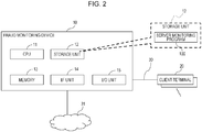
- FIG. 2 is a diagram illustrating the hardware configuration of a fraud monitoring device 10 in the fraud monitoring system 1 as an example of the embodiment.
- the fraud monitoring device (server) 10 may include a central processing unit (CPU) 11, a storage unit 12, a memory 13, an interface (IF) unit 14, and an input /output (I/O) unit 15.
- CPU central processing unit
- storage unit 12 a storage unit 12
- memory 13 a memory 13
- IF interface
- I/O input /output
- the CPU 11 executes an operating system (OS) and programs stored in the later described storage unit 12, and controls the client terminal 20 according to a request inputted from an external device which is not illustrated, for instance, a terminal managed by an administrator.
- OS operating system
- the CPU 11 executes a server monitoring program 100 described later.
- the storage unit 12 is an example of hardware which stores various data and programs.
- the storage unit 12 may be used as a secondary storage device of the fraud monitoring device 10, and may store programs such as an OS, firmware, and application, and various data.
- programs such as an OS, firmware, and application, and various data.
- a magnetic disk drive such as a hard disk drive (HDD), for instance, a solid state drive (SSD) and storage class memories (SCM) may be used as the storage unit 12.
- the storage unit 12 may store a program (server monitoring program 100) that implements all or part of various functions of the fraud monitoring device 10.
- the memory 13 is an example of hardware which stores various data and programs.
- a volatile memory for instance, a RAM such as a Dynamic RAM (DRAM) may be used as the memory 13. It is to be noted that RAM is an abbreviation for Random Access Memory.
- DRAM Dynamic RAM
- the IF unit 14 is an example of a communication interface that performs control of connection and communication with the client terminal 20 via the internal network 30.
- the fraud monitoring device 10 may include a communication interface that performs communication with a terminal (not illustrated) managed by an administrator, via the external network 31.
- a program may be downloaded using the communication interface.
- the I/O unit 15 may include at least one of an input device such as a mouse and a keyboard, and an output device such as a display and a speaker, for instance.
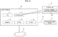
- FIG. 3 is a diagram illustrating the hardware configuration of a client terminal 20 in the fraud monitoring system 1 as an example of the embodiment.
- the client terminal 20 may include a CPU 21, a storage unit 22, a memory 23, an IF unit 24, and an I/O unit 25.
- the CPU 21 executes an OS and programs stored in the later-described storage unit 22. In the embodiment, the CPU 21 executes the later-described client terminal monitoring program 200.
- the storage unit 22 is an example of hardware which stores various data and programs.
- the storage unit 22 may be used as a secondary storage device of the client terminal 20, and may store programs such as an OS, firmware, and application, and various data.
- programs such as an OS, firmware, and application, and various data.
- a magnetic disk drive such as a HDD
- an SSD and an SCM may be used as the storage unit 22.
- the storage unit 22 may store all or part of the later-described client terminal monitoring program 200.
- the memory 23 is an example of hardware which stores various data and programs.
- a volatile memory for instance, a RAM such as a DRAM may be used as the memory 23.
- the IF unit 24 is an example of a communication interface that makes connection with the fraud monitoring device 10 via the internal network 30.
- the client terminal 20 may include a communication interface that performs communication via the external network 31 such as the Internet.
- the I/O unit 25 may include at least one of an input device such as a mouse and a keyboard, and an output device such as a display and a speaker, for instance.
- FIG. 4 is a diagram illustrating the functional configuration of the fraud monitoring device 10 in the fraud monitoring system 1 as an example of the embodiment illustrated in FIG. 2 .
- the fraud monitoring device 10 may include an internal fraud point calculation unit 40, an internal fraud point display unit 41, an alert necessity determination unit 42, and an alert instruction unit 43, as an example.
- the internal fraud point calculation unit 40 refers to internal fraud-to-point correspondence information 60 (described later) stored in the storage unit 12 of the fraud monitoring device 10, and calculates an internal fraud point for an operation or an act considered to be internal fraud for each client user.
- the operation or the act considered to be fraud is simply referred to as an act, or first internal fraud
- information on the operation or the act considered to be internal fraud is also referred to as first internal fraud information.
- the internal fraud point is a point (value) assigned to each of the acts (the first internal fraud) considered to be internal fraud, and a higher internal fraud point is assigned to an act having higher risk of leakage of information.
- the internal fraud point display unit 41 displays the internal fraud point for each client user on a display of the fraud monitoring device 10 by a dashboard function, for instance.
- the internal fraud point display unit 41 may display an internal fraud point for each of the acts, or the total of internal fraud points.
- the alert necessity determination unit 42 determines whether or not the total (accumulated total) of internal fraud points owned by a client user exceeds a predetermined threshold value. As a consequence of the determination, when the total of the internal fraud points exceeds a predetermined threshold value, the alert necessity determination unit 42 determines that an alert has to be outputted.
- the threshold value may be set in advance, for instance, by an administrator, and is allowed to be changed during the operation of the system.
- the alert instruction unit 43 issues an instruction (alert command) to output an alert to the client terminal 20.
- the processing of the internal fraud point calculation unit 40, the internal fraud point display unit 41, the alert necessity determination unit 42, and the alert instruction unit 43 is implemented by the CPU 11 executing the server monitoring program 100.
- the storage unit 12 of the fraud monitoring device 10 stores the internal fraud-to-point correspondence information 60, and a client log 61.
- the internal fraud-to-point correspondence information 60 stores the information (the later-described first internal fraud information) on the operation or the act considered to be internal fraud, and an internal fraud point for the information in association with each other.
- an internal fraud point for each of the operations or acts stored in the internal fraud-to-point correspondence information 60 is set by an administrator.
- the client log 61 stores information on the internal fraud point for each client user.
- an internal fraud point may be stored for each of the operations or the acts, or the total of internal fraud points may be stored.
- FIG. 5 is a diagram illustrating the functional configuration of the client terminal 20 in the fraud monitoring system 1 as an example of the embodiment illustrated in FIG. 3 .
- the client terminal 20 may include a first internal fraud detection unit 50, an alert instruction holding unit 51, a second internal fraud detection unit 52, an alert output unit 53, and a connection destination determination unit 54, as an example.
- the first internal fraud detection unit 50 detects an act considered to be internal fraud in the client terminal 20.
- the first internal fraud detection unit 50 then notifies the fraud monitoring device 10 of information (the first internal fraud information) on the detected act via the internal network 30.
- the alert instruction holding unit 51 holds an instruction to output an alert transmitted from the fraud monitoring device 10. In other words, even when an instruction to output an alert is received from the fraud monitoring device 10, the alert instruction holding unit 51 does not immediately output the alert to the client terminal 20, but holds (defers) the instruction (in stand-by).
- the second internal fraud detection unit 52 detects a specific event (the later-described second internal fraud) in the client terminal 20.
- the specific event will be described later.
- the alert output unit 53 outputs an alert to the client terminal 20. A specific example of the alert output will be described later. In addition, the alert output unit 53 performs control to continue alert output to the client terminal 20.
- the connection destination determination unit 54 determines whether or not the client terminal 20 is connected to the internal network 30. In addition, the connection destination determination unit 54 may determine whether the connection destination of the client terminal 20 is the internal network 30 or the external network 31.
- the processing of the first internal fraud detection unit 50, the alert instruction holding unit 51, the second internal fraud detection unit 52, the alert output unit 53, and the connection destination determination unit 54 is implemented by the CPU 21 executing the client terminal monitoring program 200.
- step S1 to S17 The processing of control in the fraud monitoring system 1 as an example of the embodiment as configured above will be described according to the flowchart (steps S1 to S17) illustrated in FIGs. 6 and 7 .
- FIG. 6 is a flowchart for explaining the processing of detection of internal fraud and alert output in the fraud monitoring system 1 according to the embodiment.
- FIG. 7 is a flowchart for explaining the recalculation of an internal fraud point and control processing of alert output in the fraud monitoring system 1 according to the embodiment.
- step S1 to S9 the processing of detection of internal fraud and alert output in the client terminal 20 in the fraud monitoring system 1 according to the embodiment will be described according to the flowchart (steps S1 to S9) illustrated in FIG. 6 .
- the server monitoring program 100 has been stored (installed) in the storage unit 12 of the fraud monitoring device 10, and the CPU 11 of the fraud monitoring device 10 has been executing the server monitoring program 100.
- the client terminal monitoring program 200 has been stored (installed) in the storage unit 22 of each client terminal 20, and the CPU 21 of the client terminal 20 has been executing the client terminal monitoring program 200.
- the client terminal 20 and the fraud monitoring device 10 are enabled to communicate with each other via the internal network 30.
- step S1 the first internal fraud detection unit 50 of each client terminal 20 detects one or more acts considered to be internal fraud, that is, the first internal fraud in the client terminal 20.
- the first internal fraud detection unit 50 notifies the fraud monitoring device 10 of information on the detected one or more acts, that is, the first internal fraud information via the internal network 30.
- one or more pieces of first internal fraud information detected in a predetermined period are collectively transmitted to the fraud monitoring device 10.
- the first internal fraud is defined in advance by an administrator as an act leading to internal fraud in an organization, and may include an act with a high probability of internal fraud.
- Such specific acts considered to be internal fraud are publicly known, and will not be elaborated upon here.
- the first internal fraud detection unit 50 of each client terminal 20 may collectively transmit one or more pieces of first internal fraud information detected in a predetermined period to the fraud monitoring device 10. Alternatively, each time a first internal fraud is detected, the first internal fraud detection unit 50 of each client terminal 20 may transmit the first internal fraud to the fraud monitoring device 10.
- step S2 the internal fraud point calculation unit 40 of the fraud monitoring device 10 calculates an internal fraud point for the pieces of first internal fraud information notified in step S1.
- the internal fraud point calculation unit 40 refers to the internal fraud-to-point correspondence information 60 stored in the storage unit 12 of the fraud monitoring device 10, and retrieves an internal fraud point for each of the pieces of first internal fraud information notified in step S1. The internal fraud point calculation unit 40 then calculates the total of the retrieved internal fraud points for each client user.
- the internal fraud point calculation unit 40 retrieves an internal fraud point of the relevant client user from the client log 61 stored in the storage unit 12. The internal fraud point calculation unit 40 then adds the total of the internal fraud points of the pieces of first internal fraud information calculated in step S2 to the retrieved internal fraud point of the relevant client user.
- the internal fraud point calculation unit 40 updates (records) the client log 61 of the client user stored in the storage unit 12 using an internal fraud point obtained as a result of adding the total of the internal fraud points.
- the internal fraud point display unit 41 of the fraud monitoring device 10 displays the (total of) internal fraud points for each client user calculated in step S3 on the display of the fraud monitoring device 10 by a dashboard function, for instance. Consequently, it is possible for an administrator to browse the (total of) internal fraud points for each client user, and to identify a client user with potentially malicious intention.
- the alert necessity determination unit 42 of the fraud monitoring device 10 determines whether or not the total of the internal fraud points owned by the client user for whom the first internal fraud has been detected in step S1 exceeds a predetermined threshold value.
- the threshold value may be set in advance, for instance, by an administrator, and is allowed to be changed during the operation of the system.
- step S5 If the total of the internal fraud points of the client user exceeds a predetermined threshold value in step S5 (see Yes route in step S5), the processing proceeds to step S6. On the other hand, if the total of the internal fraud points does not exceed a predetermined threshold value (see No route in step S5), the processing proceeds to step S11 illustrated in FIG. 7 .
- step S6 the alert instruction unit 43 of the fraud monitoring device 10 issues an instruction (output command) to output an alert to the client terminal 20 of the client user for whom the first internal fraud has been detected in step S1.
- the alert instruction holding unit 51 of the client terminal 20 holds the instruction to output an alert transmitted from the fraud monitoring device 10. In other words, even when an instruction to output an alert is received from the fraud monitoring device 10, the alert instruction holding unit 51 does not immediately output the alert to the client terminal 20, but holds the instruction (in stand-by).
- an instruction to output an alert issued by the alert instruction unit 43 of the fraud monitoring device 10 instructs the client terminal 20, which has received the instruction, to output an alert
- the output of an alert to the client terminal 20 stays in stand-by until further conditions are met.
- a function (alert notification function) preferably used for alert notification is prepared in the client terminal 20 so that alert notification may be made when further conditions are met.
- objects are instantiated so that the alert notification function is activated. Therefore, an instruction to output an alert issued by the alert instruction unit 43 may be considered as an instruction to activate the alert notification function in the client terminal 20.
- the detection of the first internal fraud is also a condition for activating the alert notification function in the client terminal 20.
- step S8 the second internal fraud detection unit 52 of the client terminal 20 checks to see if a specific event in the client terminal 20 has been detected.
- a specific event has been detected as a result of the check (see Yes route in step S8), the processing proceeds to step S9.
- the specific event is different from the first internal fraud, and may be an operation or an act having a higher risk of leakage of information than the risk of leakage of the first internal fraud detected in step S1.
- the specific event is also referred to as the second internal fraud.
- the specific event detected in step S8 may be, for instance, an operation by a client user to transmit an e-mail with an attached file to the outside of an organization, and an operation to upload data using application such as a web browser.
- the specific event may be an operation performed by a client user, such as disconnecting the client terminal 20 from a predetermined network (for instance, the internal network 30), reconnecting the client terminal 20 again to the predetermined network and transmitting data after the disconnection.
- a predetermined network for instance, the internal network 30
- the specific event may be an operation performed by a client user, such as connecting to a specific network (for instance, the external network 31) via a wireless local area network (LAN) such as Wi-Fi, and connecting to an external device via the specific network.
- a client user such as connecting to a specific network (for instance, the external network 31) via a wireless local area network (LAN) such as Wi-Fi, and connecting to an external device via the specific network.
- LAN wireless local area network
- the specific event may be an operation performed by a client user, such as inserting a USB memory into the client terminal 20, copying data to the USB memory, and writing data onto a magnetic disk such as a CD or a DVD.
- step S8 If the second internal fraud detection unit 52 of the client terminal 20 does not detect one of the specific events as described above in the client terminal 20 in step S8 (see No route in step S8), the processing skips step S9 and proceeds to step S10. It is to be noted that in the embodiment, the second internal fraud detection unit 52 determines whether or not a specific event has been detected within a predetermined period.
- step S9 the alert output unit 53 of the client terminal 20 outputs an alert to the client terminal 20.
- the alert output unit 53 displays a message indicating that an act considered to be internal fraud has been performed, or a message indicating that an act with a high probability of internal fraud has been detected.
- an alert may be issued by voice via a speaker of the client terminal 20.
- steps S7 to S9 illustrated in FIG. 6 is performed, and thus even when an act considered to be internal fraud is performed in the client terminal 20, the client terminal 20 is not immediately notified of an alert. Only after a specific event is detected in step S8, the client terminal 20 is notified of an alert. This enables an alert to be displayed at appropriate timing without losing the significance of the alert.
- the client terminal 20 Since the processing in steps S7 to S9 is performed by the client terminal monitoring program 200, the client terminal 20 is notified of an alert even when the client terminal 20 is not connected to the internal network 30. In other words, even when the client terminal 20 is not connected to the internal network 30, it is possible to control the client terminal 20. Consequently, any client user disconnected from the internal network 30 is made to feel that the client user is being monitored, and thus a deterrent effect on internal fraud may be expected.
- the fraud monitoring device 10 when the first internal fraud detection unit 50 detects multiple operations considered to be internal fraud in step S1, the fraud monitoring device 10 is notified of the multiple operations collectively. However, each time the first internal fraud is detected, the fraud monitoring device 10 may be notified of the first internal fraud. In this case, the processing in steps S1 to S9 may be repeatedly performed within in a predetermined period.
- step S9 illustrated in FIG. 6 After the client terminal 20 outputs an alert in step S9 illustrated in FIG. 6 , the processing proceeds to step S10 illustrated in FIG. 7 .
- step S10 illustrated in FIG. 7 the connection destination determination unit 54 of the client terminal 20 determines whether or not the client terminal 20 is connected to the internal network 30.
- step S10 If it is determined in step S10 that the client terminal 20 is connected to the internal network 30 (see Yes route in step S10), the processing proceeds to step S11. The same processing as step S1 described above is performed. Specifically, the first internal fraud detection unit 50 of the client terminal 20 notifies the fraud monitoring device 10 of one or more pieces of first internal fraud information detected in the client terminal 20, via the internal network 30.
- step S11 the first internal fraud detection unit 50 of the client terminal 20 also transmits a client user identifier to the fraud monitoring device 10 along with the detected first internal fraud information.
- the internal fraud point calculation unit 40 of the fraud monitoring device 10 then performs the same processing as step S2 described above, and recalculates the internal fraud point of the client user.
- the internal fraud point calculation unit 40 refers to the internal fraud-to-point correspondence information 60 stored in the storage unit 12 of the fraud monitoring device 10, and retrieves an internal fraud point for each the pieces of first internal fraud information detected by the first internal fraud detection unit 50 in step S10. The internal fraud point calculation unit 40 then calculates the total of the retrieved internal fraud point for each client user.
- the internal fraud point calculation unit 40 retrieves an internal fraud point of the client user from the client log 61 stored in the storage unit 12 of the fraud monitoring device 10.
- the internal fraud point calculation unit 40 then performs recalculation by adding the total of the internal fraud points of the pieces of first internal fraud information calculated in step S11 to the retrieved internal fraud point of the client user.
- the internal fraud point calculation unit 40 updates (records) the client log 61 of the client user stored in the storage unit 12 using an internal fraud point obtained as a result of the recalculation.
- the internal fraud point display unit 41 of the fraud monitoring device 10 displays the (total of) internal fraud points for each client user obtained by recalculation in step S12 on, for instance, a dashboard of the display of the fraud monitoring device 10.
- the alert necessity determination unit 42 of the fraud monitoring device 10 determines whether or not the total of the internal fraud points owned by the client user for whom the first internal fraud has been detected in step S10 exceeds a predetermined threshold value.
- the threshold value may be set in advance, for instance, by an administrator, and is allowed to be changed during the operation of the system. In addition, the threshold value may be set to a value different from the threshold value used in step S5.
- step S14 If the total of the internal fraud points of the client user exceeds a predetermined threshold value in step S14 (see Yes route in step S14), the processing proceeds to step S15.
- step S15 the alert instruction unit 43 of the fraud monitoring device 10 issues an instruction to continue output of an alert to the client user for whom the first internal fraud has been detected in step S10.
- the alert output unit 53 of the client terminal 20 receives an instruction to continue output of an alert from the alert instruction unit 43, and continues output of an alert in the client terminal 20. For instance, when the alert output unit 53 displays an alert on the display of the client terminal 20 in step S9, the alert output unit 53 continues to display the alert. For instance, when the alert output unit 53 notifies of an alert by voice from a speaker of the client terminal 20 in step S9, the notification is continued. The processing is then completed.
- step S14 when the total of the internal fraud points of the client user does not exceed a predetermined threshold value (see No route in step S14), the processing proceeds to step S16.
- step S16 the alert instruction unit 43 of the fraud monitoring device 10 issues an instruction to cancel the output of an alert to the client terminal 20 of the client user for whom the first internal fraud has been detected in step S10.
- the alert output unit 53 of the client terminal 20 cancels the output of an alert, in other words, stops the output of an alert in the client terminal 20.
- the alert output unit 53 receives an instruction to cancel the output of an alert from the alert instruction unit 43, and performs control to stop the output of the alert in the client terminal 20. The processing is then completed.
- connection destination determination unit 54 of the client terminal 20 determines that the client terminal 20 is not connected to the internal network 30 in step S10 (see No route in step S10), the processing proceeds to step S17.
- step S17 when the second internal fraud detection unit 52 of the client terminal 20 detects similar second internal fraud and the alert has been already outputted in step S9 illustrated in FIG. 6 , the processing is continued (output of the alert is continued). The processing is then completed.
- step S17 when the second internal fraud detection unit 52 of the client terminal 20 detects similar second internal fraud and the alert has not been outputted in step S9 illustrated in FIG. 6 , the alert is outputted. The processing is then completed.
- step S11 may be different from the internal fraud point calculated in step S2.
- an internal fraud point corresponding to the stopped act is subtracted from the total by the recalculation in step S11.
- the display of the alert is cancelled in step S16.
- step S17 illustrated in FIG. 7 is performed by the client terminal monitoring program 200. Therefore, also in the client terminal 20 disconnected from the internal network 30, when an act similar to a detected act is detected, the output of the alert is repeated. Thus, it is possible to make any client user disconnected from the internal network 30 feel that the client user is being monitored.
- the alert instruction holding unit 51 of the client terminal 20 does not immediately output an alert to a client, but holds the alert. Only after a specific event (the second internal fraud) is detected, the alert output unit 53 of the client terminal 20 notifies a client of an alert. This enables an alert to be displayed at appropriate timing without losing the significance of the alert.
- the internal fraud point calculation unit 40 of the fraud monitoring device 10 recalculates the internal fraud point of the corresponding client user.
- the alert instruction unit 43 of the fraud monitoring device 10 cancels (stops) the output of an alert.
- the client terminal monitoring program 200 is installed in the client terminal 20, and the second internal fraud detection unit 52 and the alert output unit 53 are implemented by the client terminal monitoring program 200. Therefore, even when the client terminal 20 is not connected to the internal network 30, detection of a specific event (the second internal fraud) made by the second internal fraud detection unit 52 allows the alert output unit 53 to (continue the) display an alert. Consequently, even when the client terminal 20 is disconnected from the internal network 30, it is possible to continue control of alert display on the client terminal 20 as well as to make the client user feel that the client user is being monitored.
- the second internal fraud detection unit 52 and the alert output unit 53 are implemented by the client terminal monitoring program 200. Therefore, even when the client terminal 20 is not connected to the internal network 30, detection of a specific event (the second internal fraud) made by the second internal fraud detection unit 52 allows the alert output unit 53 to (continue the) display an alert. Consequently, even when the client terminal 20 is disconnected from the internal network 30, it is possible to continue control of alert display on the client terminal 20 as well as to make the client user feel
- the second internal fraud detection unit 52 of the client terminal 20 detects the second internal fraud, which is an act having higher risk of leakage of information than the risk of leakage of the first internal fraud, for instance, an operation of connecting to the external network 31. In this manner, the second internal fraud detection unit 52 of the client terminal 20 detects the second internal fraud, thereby making it possible to identify a client user which has performs an act with a high probability of internal fraud, for instance, an act with a high possibility of leaking information to the outside.
- step S1 considered to be internal fraud may be included in the range of assigned work a client user or may be authorized by the organization.
- exception handling is provided so that control is performed to avoid the output of an alert.
- FIG. 8 is a flowchart illustrating the exception handling in a fraud monitoring system 1 according to a modification.
- FIG. 9 is a diagram illustrating the functional configuration of a fraud monitoring device 10 in the fraud monitoring system 1 according to the modification. The exception handling in the fraud monitoring system 1 according to the modification will be described according to the flowchart (steps T1 to T5) illustrated in FIG. 8 .
- the storage unit 12 of the fraud monitoring device 10 stores a white list 62 for registering authorized client information for the exception handling as illustrated in FIG. 9 .
- the client user when there is a possibility that a client user performs an operation or an act considered to be internal fraud as the assigned work, the client user informs an administrator or the like of the possibility.
- the administrator or the like acknowledges that the client user is an authorized client for the exception handling, and registers information (for instance, a client user identifier) on the client user and an operation or an act as the assigned work in the white list 62 in association with each other.
- authorization may be obtained from a superior, or checking is performed to see if an operation is authorized as the assigned work, but the authorization is not limited to this.
- each component labeled with the same symbol as a previously-mentioned symbol indicates the same component as the previously-mentioned component and will not be elaborated upon here.
- step T1 illustrated in FIG. 8 the first internal fraud detection unit 50 detects the first internal fraud in the client terminal 20 of a client user who performs an act considered to be internal fraud as the assigned work.
- the alert necessity determination unit 42 of the fraud monitoring device 10 refers to the white list 62 stored in the storage unit 12 determines whether or not the information on the client user for whom the first internal fraud has been detected in step T1 is stored in the white list 62.
- the alert necessity determination unit 42 checks to see if information on the first internal fraud detected in step T1 and the identifier of the client are stored in the white list 62 in association with each other. If a result of the checking confirms that the information on the first internal fraud detected in step T1 and the identifier of the client are stored in the white list 62 in association with each other, the alert necessity determination unit 42 determines that the exception handling has to be performed.
- step T2 If the alert necessity determination unit 42 determines in step T2 that the exception handling has to be performed (see Yes route in step T2), the processing proceed to step T3.
- step T3 the alert instruction unit 43 of the fraud monitoring device 10 instructs the client terminal 20 to avoid the output of an alert.
- the alert necessity determination unit 42 records issuance of the instruction to avoid the output of an alert in the client log 61 stored in the storage unit 12.
- the alert output unit 53 of the client terminal 20 receives an instruction to avoid output of an alert from the alert instruction unit 43, and performs control (not to output) to avoid the output of an alert in the client terminal 20, and completes the processing.
- step T2 determines in step T2 that the exception handling does not have to be performed (see No route in step T2), the processing illustrated in steps T3 to T5 in FIG. 8 is not performed, and the processing is completed.
- the processing proceeds to normal alert notification processing (for instance, the processing in step S2 or S9 illustrated in FIG. 6 ).
- the fraud monitoring system 1 of the modification when there is a possibility that an act considered to be internal fraud is performed as the assigned work of a client user, the act and the client user are registered in the white list 62 in association with each other. Consequently, it is possible to avoid outputting an alert to the client terminal 20 of a client user with no malicious intention, and to control alert display in an appropriate manner.
- the internal fraud point is calculated for each client user.
- the internal fraud point may be calculated for each client terminal 20.
- the first internal fraud detection unit 50 of the client terminal 20 may transmit information for identifying the client terminal 20 along with the first internal fraud information.
- the storage unit 12 of the fraud monitoring device 10 may store the log for each client terminal 20.
- the alert control processing illustrated in FIGs. 6 and 7 may be performed on such a client user.
- the white list 62 stored in the storage unit 12 is referred to, and when a client user is registered in the white list 62, a threshold value higher than the threshold values of other client users may be set in the processing in steps S5 and S14.
Landscapes
- Engineering & Computer Science (AREA)
- Computer Security & Cryptography (AREA)
- Computer Hardware Design (AREA)
- General Engineering & Computer Science (AREA)
- Theoretical Computer Science (AREA)
- Software Systems (AREA)
- Computing Systems (AREA)
- Physics & Mathematics (AREA)
- General Physics & Mathematics (AREA)
- Computer Networks & Wireless Communication (AREA)
- Signal Processing (AREA)
- Technology Law (AREA)
- Health & Medical Sciences (AREA)
- Bioethics (AREA)
- General Health & Medical Sciences (AREA)
- Emergency Management (AREA)
- Business, Economics & Management (AREA)
- Debugging And Monitoring (AREA)
- Computer And Data Communications (AREA)
Abstract
Description
- The embodiments discussed herein are related to a fraud monitoring program, a fraud monitoring method, and an information processing system.
- Internal fraud is one of typical causes for leakage of information in an organization such as a company. Thus, a fraud monitoring device which monitors internal fraud is installed in an organization, and when an operation or an act considered to be internal fraud (also simply referred to as fraud operation) is detected by the fraud monitoring device, a client (terminal) who has committed the internal fraud is identified, and an alert (warning) is displayed. Consequently, the opportunity of committing internal fraud is reduced, and leakage of information of the organization to the outside is avoided. Related techniques are disclosed in, for example, Japanese Laid-open Patent Publication Nos.
2010-211257 2007-241337 - In such a fraud monitoring technique in the related art, while a client terminal, on which alert display is to be performed, is connected to a predetermined network, a fraud monitoring device performs control of alert display on the client terminal. Thus, when the client terminal, on which alert display is to be performed, is disconnected from the predetermined network, it is difficult to control the client terminal.
- In addition, in the fraud monitoring technique in the related art, every time an act leading to internal fraud (for instance, an act of inserting a Universal Serial Bus (USB) memory into a slot) is detected by the fraud monitoring device, an alert is displayed. Such frequent alerts may be viewed as having little importance.
- In an aspect, it is aimed to display an alert on a client terminal at appropriate timing.
- According to an aspect of the embodiments, a fraud monitoring method, performed by a computer, includes steps of: transmitting information on an operation or an act in the computer to a management device via a first network; and outputting an alert in response to detection of a specific event after an instruction to activate an alert notification function is received from the management device which has detected based on the information that a condition for activating the alert notification function in the computer is met.
- According to an embodiment, a fraud monitoring system is capable of displaying an alert on a client terminal at appropriate timing.
-
-
FIG. 1 is a diagram illustrating the hardware configuration of a fraud monitoring system as an example of an embodiment; -
FIG. 2 is a diagram illustrating the hardware configuration of a fraud monitoring device in the fraud monitoring system as an example of the embodiment; -
FIG. 3 is a diagram illustrating the hardware configuration of a client terminal in the fraud monitoring system as an example of the embodiment; -
FIG. 4 is a diagram illustrating the functional configuration of the fraud monitoring device in the fraud monitoring system as an example of the embodiment; -
FIG. 5 is a diagram illustrating the functional configuration of the client terminal in the fraud monitoring system as an example of the embodiment; -
FIG. 6 is a flowchart illustrating the processing of detection of internal fraud and alert output in the fraud monitoring system as an example of the embodiment; -
FIG. 7 is a flowchart illustrating the recalculation of internal fraud point and the control processing for alert output in the fraud monitoring system as an example of the embodiment; -
FIG. 8 is a flowchart illustrating the exception handling in a fraud monitoring system as a modification; and -
FIG. 9 is a diagram illustrating the functional configuration of a fraud monitoring device in the fraud monitoring system as the modification. - Hereinafter, an embodiment of the present disclosure will be described with reference to the drawings. However, the embodiment described below is merely an example, and it is not intended to exclude various modifications and technical applications which are not explicitly described below. For instance, the embodiment may be variously modified and practiced in a range not departing from the spirit of the present disclosure. It is to be noted that in the drawings used in the embodiment below, components labeled with the same symbol indicate the same or similar components unless otherwise stated.
-
FIG. 1 is a diagram illustrating the hardware configuration of afraud monitoring system 1 as an example of an embodiment. - As illustrated in
FIG. 1 , thefraud monitoring system 1 includes fraud monitoring device (server) 10, and one ormultiple client terminals symbols symbol 20 is used to indicate any client terminal. Thefraud monitoring device 10 and theclient terminal 20 are connected via aninternal network 30 such as an intranet. - Alternatively, a client user may disconnect the
client terminal 20 from theinternal network 30, and connect theclient terminal 20 to anexternal network 31. - Then, the
fraud monitoring device 10 may be also connected to theexternal network 31 to communicate with, for instance, a terminal (not illustrated) managed by an administrator. - Although the
fraud monitoring system 1 includes onefraud monitoring device 10 inFIG. 1 , thefraud monitoring system 1 may include multiplefraud monitoring devices 10. -
FIG. 2 is a diagram illustrating the hardware configuration of afraud monitoring device 10 in thefraud monitoring system 1 as an example of the embodiment. - As illustrated in
FIG. 2 , the fraud monitoring device (server) 10 may include a central processing unit (CPU) 11, astorage unit 12, amemory 13, an interface (IF)unit 14, and an input /output (I/O)unit 15. - The
CPU 11 executes an operating system (OS) and programs stored in the later describedstorage unit 12, and controls theclient terminal 20 according to a request inputted from an external device which is not illustrated, for instance, a terminal managed by an administrator. In the embodiment, theCPU 11 executes aserver monitoring program 100 described later. - The
storage unit 12 is an example of hardware which stores various data and programs. For instance, thestorage unit 12 may be used as a secondary storage device of thefraud monitoring device 10, and may store programs such as an OS, firmware, and application, and various data. In addition to a magnetic disk drive such as a hard disk drive (HDD), for instance, a solid state drive (SSD) and storage class memories (SCM) may be used as thestorage unit 12. Thestorage unit 12 may store a program (server monitoring program 100) that implements all or part of various functions of thefraud monitoring device 10. - The
memory 13 is an example of hardware which stores various data and programs. A volatile memory, for instance, a RAM such as a Dynamic RAM (DRAM) may be used as thememory 13. It is to be noted that RAM is an abbreviation for Random Access Memory. - The
IF unit 14 is an example of a communication interface that performs control of connection and communication with theclient terminal 20 via theinternal network 30. Thefraud monitoring device 10 may include a communication interface that performs communication with a terminal (not illustrated) managed by an administrator, via theexternal network 31. A program may be downloaded using the communication interface. - The I/
O unit 15 may include at least one of an input device such as a mouse and a keyboard, and an output device such as a display and a speaker, for instance. -
FIG. 3 is a diagram illustrating the hardware configuration of aclient terminal 20 in thefraud monitoring system 1 as an example of the embodiment. - As illustrated in
FIG. 3 , theclient terminal 20 may include aCPU 21, astorage unit 22, amemory 23, anIF unit 24, and an I/O unit 25. - The
CPU 21 executes an OS and programs stored in the later-describedstorage unit 22. In the embodiment, theCPU 21 executes the later-described clientterminal monitoring program 200. - The
storage unit 22 is an example of hardware which stores various data and programs. For instance, thestorage unit 22 may be used as a secondary storage device of theclient terminal 20, and may store programs such as an OS, firmware, and application, and various data. In addition to a magnetic disk drive such as a HDD, for instance, an SSD and an SCM may be used as thestorage unit 22. Thestorage unit 22 may store all or part of the later-described clientterminal monitoring program 200. - The
memory 23 is an example of hardware which stores various data and programs. A volatile memory, for instance, a RAM such as a DRAM may be used as thememory 23. - The
IF unit 24 is an example of a communication interface that makes connection with thefraud monitoring device 10 via theinternal network 30. Theclient terminal 20 may include a communication interface that performs communication via theexternal network 31 such as the Internet. - The I/
O unit 25 may include at least one of an input device such as a mouse and a keyboard, and an output device such as a display and a speaker, for instance. -
FIG. 4 is a diagram illustrating the functional configuration of thefraud monitoring device 10 in thefraud monitoring system 1 as an example of the embodiment illustrated inFIG. 2 . - As illustrated in
FIG. 4 , thefraud monitoring device 10 may include an internal fraudpoint calculation unit 40, an internal fraudpoint display unit 41, an alertnecessity determination unit 42, and analert instruction unit 43, as an example. - The internal fraud
point calculation unit 40 refers to internal fraud-to-point correspondence information 60 (described later) stored in thestorage unit 12 of thefraud monitoring device 10, and calculates an internal fraud point for an operation or an act considered to be internal fraud for each client user. In the embodiment, the operation or the act considered to be fraud is simply referred to as an act, or first internal fraud, and information on the operation or the act considered to be internal fraud is also referred to as first internal fraud information. - In the embodiment, the internal fraud point is a point (value) assigned to each of the acts (the first internal fraud) considered to be internal fraud, and a higher internal fraud point is assigned to an act having higher risk of leakage of information.
- The internal fraud
point display unit 41 displays the internal fraud point for each client user on a display of thefraud monitoring device 10 by a dashboard function, for instance. When multiple acts considered to be internal fraud are detected in eachclient terminal 20, the internal fraudpoint display unit 41 may display an internal fraud point for each of the acts, or the total of internal fraud points. - The alert
necessity determination unit 42 determines whether or not the total (accumulated total) of internal fraud points owned by a client user exceeds a predetermined threshold value. As a consequence of the determination, when the total of the internal fraud points exceeds a predetermined threshold value, the alertnecessity determination unit 42 determines that an alert has to be outputted. - The threshold value may be set in advance, for instance, by an administrator, and is allowed to be changed during the operation of the system.
- The
alert instruction unit 43 issues an instruction (alert command) to output an alert to theclient terminal 20. - In the embodiment, the processing of the internal fraud
point calculation unit 40, the internal fraudpoint display unit 41, the alertnecessity determination unit 42, and thealert instruction unit 43 is implemented by theCPU 11 executing theserver monitoring program 100. - The
storage unit 12 of thefraud monitoring device 10 stores the internal fraud-to-point correspondence information 60, and aclient log 61. - The internal fraud-to-
point correspondence information 60 stores the information (the later-described first internal fraud information) on the operation or the act considered to be internal fraud, and an internal fraud point for the information in association with each other. In the embodiment, an internal fraud point for each of the operations or acts stored in the internal fraud-to-point correspondence information 60 is set by an administrator. - The
client log 61 stores information on the internal fraud point for each client user. In the embodiment, when multiple operations or acts considered to be internal fraud are detected in a client terminal, an internal fraud point may be stored for each of the operations or the acts, or the total of internal fraud points may be stored. -
FIG. 5 is a diagram illustrating the functional configuration of theclient terminal 20 in thefraud monitoring system 1 as an example of the embodiment illustrated inFIG. 3 . - As illustrated in
FIG. 5 , theclient terminal 20 according to the embodiment may include a first internalfraud detection unit 50, an alertinstruction holding unit 51, a second internalfraud detection unit 52, analert output unit 53, and a connectiondestination determination unit 54, as an example. - The first internal
fraud detection unit 50 detects an act considered to be internal fraud in theclient terminal 20. The first internalfraud detection unit 50 then notifies thefraud monitoring device 10 of information (the first internal fraud information) on the detected act via theinternal network 30. - The alert
instruction holding unit 51 holds an instruction to output an alert transmitted from thefraud monitoring device 10. In other words, even when an instruction to output an alert is received from thefraud monitoring device 10, the alertinstruction holding unit 51 does not immediately output the alert to theclient terminal 20, but holds (defers) the instruction (in stand-by). - The second internal
fraud detection unit 52 detects a specific event (the later-described second internal fraud) in theclient terminal 20. The specific event will be described later. - The
alert output unit 53 outputs an alert to theclient terminal 20. A specific example of the alert output will be described later. In addition, thealert output unit 53 performs control to continue alert output to theclient terminal 20. - The connection
destination determination unit 54 determines whether or not theclient terminal 20 is connected to theinternal network 30. In addition, the connectiondestination determination unit 54 may determine whether the connection destination of theclient terminal 20 is theinternal network 30 or theexternal network 31. - In the embodiment, the processing of the first internal
fraud detection unit 50, the alertinstruction holding unit 51, the second internalfraud detection unit 52, thealert output unit 53, and the connectiondestination determination unit 54 is implemented by theCPU 21 executing the clientterminal monitoring program 200. - The processing of control in the
fraud monitoring system 1 as an example of the embodiment as configured above will be described according to the flowchart (steps S1 to S17) illustrated inFIGs. 6 and7 . -
FIG. 6 is a flowchart for explaining the processing of detection of internal fraud and alert output in thefraud monitoring system 1 according to the embodiment.FIG. 7 is a flowchart for explaining the recalculation of an internal fraud point and control processing of alert output in thefraud monitoring system 1 according to the embodiment. - First, the processing of detection of internal fraud and alert output in the
client terminal 20 in thefraud monitoring system 1 according to the embodiment will be described according to the flowchart (steps S1 to S9) illustrated inFIG. 6 . - Before the processing is started, the
server monitoring program 100 has been stored (installed) in thestorage unit 12 of thefraud monitoring device 10, and theCPU 11 of thefraud monitoring device 10 has been executing theserver monitoring program 100. - The client
terminal monitoring program 200 has been stored (installed) in thestorage unit 22 of eachclient terminal 20, and theCPU 21 of theclient terminal 20 has been executing the clientterminal monitoring program 200. - In addition, the
client terminal 20 and thefraud monitoring device 10 are enabled to communicate with each other via theinternal network 30. - In step S1, the first internal
fraud detection unit 50 of eachclient terminal 20 detects one or more acts considered to be internal fraud, that is, the first internal fraud in theclient terminal 20. The first internalfraud detection unit 50 notifies thefraud monitoring device 10 of information on the detected one or more acts, that is, the first internal fraud information via theinternal network 30. In the embodiment, one or more pieces of first internal fraud information detected in a predetermined period are collectively transmitted to thefraud monitoring device 10. - The first internal fraud is defined in advance by an administrator as an act leading to internal fraud in an organization, and may include an act with a high probability of internal fraud. Such specific acts considered to be internal fraud are publicly known, and will not be elaborated upon here.
- In the processing of step S1, the first internal
fraud detection unit 50 of eachclient terminal 20 may collectively transmit one or more pieces of first internal fraud information detected in a predetermined period to thefraud monitoring device 10. Alternatively, each time a first internal fraud is detected, the first internalfraud detection unit 50 of eachclient terminal 20 may transmit the first internal fraud to thefraud monitoring device 10. - In subsequent step S2, the internal fraud
point calculation unit 40 of thefraud monitoring device 10 calculates an internal fraud point for the pieces of first internal fraud information notified in step S1. - Specifically, first, the internal fraud
point calculation unit 40 refers to the internal fraud-to-point correspondence information 60 stored in thestorage unit 12 of thefraud monitoring device 10, and retrieves an internal fraud point for each of the pieces of first internal fraud information notified in step S1. The internal fraudpoint calculation unit 40 then calculates the total of the retrieved internal fraud points for each client user. - Subsequently, based on a client user identifier, the internal fraud
point calculation unit 40 retrieves an internal fraud point of the relevant client user from theclient log 61 stored in thestorage unit 12. The internal fraudpoint calculation unit 40 then adds the total of the internal fraud points of the pieces of first internal fraud information calculated in step S2 to the retrieved internal fraud point of the relevant client user. - Consequently, the total of internal fraud points for one or more acts considered to be internal fraud, which have been conducted by a client user, is determined. A higher value of the total indicates a higher risk of leakage of information.
- In subsequent step S3, the internal fraud
point calculation unit 40 updates (records) theclient log 61 of the client user stored in thestorage unit 12 using an internal fraud point obtained as a result of adding the total of the internal fraud points. - In subsequent step S4, the internal fraud
point display unit 41 of thefraud monitoring device 10 displays the (total of) internal fraud points for each client user calculated in step S3 on the display of thefraud monitoring device 10 by a dashboard function, for instance. Consequently, it is possible for an administrator to browse the (total of) internal fraud points for each client user, and to identify a client user with potentially malicious intention. - In subsequent step S5, the alert
necessity determination unit 42 of thefraud monitoring device 10 determines whether or not the total of the internal fraud points owned by the client user for whom the first internal fraud has been detected in step S1 exceeds a predetermined threshold value. The threshold value may be set in advance, for instance, by an administrator, and is allowed to be changed during the operation of the system. - If the total of the internal fraud points of the client user exceeds a predetermined threshold value in step S5 (see Yes route in step S5), the processing proceeds to step S6. On the other hand, if the total of the internal fraud points does not exceed a predetermined threshold value (see No route in step S5), the processing proceeds to step S11 illustrated in
FIG. 7 . - In step S6, the
alert instruction unit 43 of thefraud monitoring device 10 issues an instruction (output command) to output an alert to theclient terminal 20 of the client user for whom the first internal fraud has been detected in step S1. - In subsequent step S7, the alert
instruction holding unit 51 of theclient terminal 20 holds the instruction to output an alert transmitted from thefraud monitoring device 10. In other words, even when an instruction to output an alert is received from thefraud monitoring device 10, the alertinstruction holding unit 51 does not immediately output the alert to theclient terminal 20, but holds the instruction (in stand-by). - Specifically, although an instruction to output an alert issued by the
alert instruction unit 43 of thefraud monitoring device 10 instructs theclient terminal 20, which has received the instruction, to output an alert, the output of an alert to theclient terminal 20 stays in stand-by until further conditions are met. Thus, a function (alert notification function) preferably used for alert notification is prepared in theclient terminal 20 so that alert notification may be made when further conditions are met. For instance, as preparation for the alert notification function, objects are instantiated so that the alert notification function is activated. Therefore, an instruction to output an alert issued by thealert instruction unit 43 may be considered as an instruction to activate the alert notification function in theclient terminal 20. - Similarly, since an instruction to activate the alert notification function in the
client terminal 20 is triggered by detection of the first internal fraud, the detection of the first internal fraud is also a condition for activating the alert notification function in theclient terminal 20. - In subsequent step S8, the second internal
fraud detection unit 52 of theclient terminal 20 checks to see if a specific event in theclient terminal 20 has been detected. When a specific event has been detected as a result of the check (see Yes route in step S8), the processing proceeds to step S9. - In the embodiment, the specific event is different from the first internal fraud, and may be an operation or an act having a higher risk of leakage of information than the risk of leakage of the first internal fraud detected in step S1. In the embodiment, the specific event is also referred to as the second internal fraud.
- The specific event detected in step S8 may be, for instance, an operation by a client user to transmit an e-mail with an attached file to the outside of an organization, and an operation to upload data using application such as a web browser.
- The specific event may be an operation performed by a client user, such as disconnecting the
client terminal 20 from a predetermined network (for instance, the internal network 30), reconnecting theclient terminal 20 again to the predetermined network and transmitting data after the disconnection. - In addition, the specific event may be an operation performed by a client user, such as connecting to a specific network (for instance, the external network 31) via a wireless local area network (LAN) such as Wi-Fi, and connecting to an external device via the specific network.
- In addition, the specific event may be an operation performed by a client user, such as inserting a USB memory into the
client terminal 20, copying data to the USB memory, and writing data onto a magnetic disk such as a CD or a DVD. - If the second internal
fraud detection unit 52 of theclient terminal 20 does not detect one of the specific events as described above in theclient terminal 20 in step S8 (see No route in step S8), the processing skips step S9 and proceeds to step S10. It is to be noted that in the embodiment, the second internalfraud detection unit 52 determines whether or not a specific event has been detected within a predetermined period. - In step S9, the
alert output unit 53 of theclient terminal 20 outputs an alert to theclient terminal 20. For instance, on the display of theclient terminal 20, thealert output unit 53 displays a message indicating that an act considered to be internal fraud has been performed, or a message indicating that an act with a high probability of internal fraud has been detected. Alternatively, an alert may be issued by voice via a speaker of theclient terminal 20. - As described above, the processing in steps S7 to S9 illustrated in
FIG. 6 is performed, and thus even when an act considered to be internal fraud is performed in theclient terminal 20, theclient terminal 20 is not immediately notified of an alert. Only after a specific event is detected in step S8, theclient terminal 20 is notified of an alert. This enables an alert to be displayed at appropriate timing without losing the significance of the alert. - Since the processing in steps S7 to S9 is performed by the client
terminal monitoring program 200, theclient terminal 20 is notified of an alert even when theclient terminal 20 is not connected to theinternal network 30. In other words, even when theclient terminal 20 is not connected to theinternal network 30, it is possible to control theclient terminal 20. Consequently, any client user disconnected from theinternal network 30 is made to feel that the client user is being monitored, and thus a deterrent effect on internal fraud may be expected. - In the embodiment, when the first internal
fraud detection unit 50 detects multiple operations considered to be internal fraud in step S1, thefraud monitoring device 10 is notified of the multiple operations collectively. However, each time the first internal fraud is detected, thefraud monitoring device 10 may be notified of the first internal fraud. In this case, the processing in steps S1 to S9 may be repeatedly performed within in a predetermined period. - Next, the recalculation of an internal fraud point and control processing of alert output in the
fraud monitoring system 1 according to an embodiment will be described according to the flowchart (steps S10 to S17) illustrated inFIG. 7 . - After the
client terminal 20 outputs an alert in step S9 illustrated inFIG. 6 , the processing proceeds to step S10 illustrated inFIG. 7 . - In step S10 illustrated in
FIG. 7 , the connectiondestination determination unit 54 of theclient terminal 20 determines whether or not theclient terminal 20 is connected to theinternal network 30. - If it is determined in step S10 that the
client terminal 20 is connected to the internal network 30 (see Yes route in step S10), the processing proceeds to step S11. The same processing as step S1 described above is performed. Specifically, the first internalfraud detection unit 50 of theclient terminal 20 notifies thefraud monitoring device 10 of one or more pieces of first internal fraud information detected in theclient terminal 20, via theinternal network 30. - In step S11, the first internal
fraud detection unit 50 of theclient terminal 20 also transmits a client user identifier to thefraud monitoring device 10 along with the detected first internal fraud information. - The internal fraud
point calculation unit 40 of thefraud monitoring device 10 then performs the same processing as step S2 described above, and recalculates the internal fraud point of the client user. - Specifically, the internal fraud
point calculation unit 40 refers to the internal fraud-to-point correspondence information 60 stored in thestorage unit 12 of thefraud monitoring device 10, and retrieves an internal fraud point for each the pieces of first internal fraud information detected by the first internalfraud detection unit 50 in step S10. The internal fraudpoint calculation unit 40 then calculates the total of the retrieved internal fraud point for each client user. - Subsequently, based on a client user identifier, the internal fraud
point calculation unit 40 retrieves an internal fraud point of the client user from theclient log 61 stored in thestorage unit 12 of thefraud monitoring device 10. The internal fraudpoint calculation unit 40 then performs recalculation by adding the total of the internal fraud points of the pieces of first internal fraud information calculated in step S11 to the retrieved internal fraud point of the client user. - In subsequent step S12, the internal fraud
point calculation unit 40 updates (records) theclient log 61 of the client user stored in thestorage unit 12 using an internal fraud point obtained as a result of the recalculation. - In subsequent step S13, the internal fraud
point display unit 41 of thefraud monitoring device 10 displays the (total of) internal fraud points for each client user obtained by recalculation in step S12 on, for instance, a dashboard of the display of thefraud monitoring device 10. - In subsequent step S14, the alert
necessity determination unit 42 of thefraud monitoring device 10 determines whether or not the total of the internal fraud points owned by the client user for whom the first internal fraud has been detected in step S10 exceeds a predetermined threshold value. The threshold value may be set in advance, for instance, by an administrator, and is allowed to be changed during the operation of the system. In addition, the threshold value may be set to a value different from the threshold value used in step S5. - If the total of the internal fraud points of the client user exceeds a predetermined threshold value in step S14 (see Yes route in step S14), the processing proceeds to step S15.
- In step S15, the
alert instruction unit 43 of thefraud monitoring device 10 issues an instruction to continue output of an alert to the client user for whom the first internal fraud has been detected in step S10. - The
alert output unit 53 of theclient terminal 20 receives an instruction to continue output of an alert from thealert instruction unit 43, and continues output of an alert in theclient terminal 20. For instance, when thealert output unit 53 displays an alert on the display of theclient terminal 20 in step S9, thealert output unit 53 continues to display the alert. For instance, when thealert output unit 53 notifies of an alert by voice from a speaker of theclient terminal 20 in step S9, the notification is continued. The processing is then completed. - On the other hand, in step S14, when the total of the internal fraud points of the client user does not exceed a predetermined threshold value (see No route in step S14), the processing proceeds to step S16.
- In step S16, the
alert instruction unit 43 of thefraud monitoring device 10 issues an instruction to cancel the output of an alert to theclient terminal 20 of the client user for whom the first internal fraud has been detected in step S10. - The
alert output unit 53 of theclient terminal 20 cancels the output of an alert, in other words, stops the output of an alert in theclient terminal 20. - The
alert output unit 53 receives an instruction to cancel the output of an alert from thealert instruction unit 43, and performs control to stop the output of the alert in theclient terminal 20. The processing is then completed. - If the connection
destination determination unit 54 of theclient terminal 20 determines that theclient terminal 20 is not connected to theinternal network 30 in step S10 (see No route in step S10), the processing proceeds to step S17. - In step S17, when the second internal
fraud detection unit 52 of theclient terminal 20 detects similar second internal fraud and the alert has been already outputted in step S9 illustrated inFIG. 6 , the processing is continued (output of the alert is continued). The processing is then completed. - In step S17, when the second internal
fraud detection unit 52 of theclient terminal 20 detects similar second internal fraud and the alert has not been outputted in step S9 illustrated inFIG. 6 , the alert is outputted. The processing is then completed. - Although the specific details of the processing of recalculation in step S11 illustrated in
FIG. 7 are the same as in the processing in step S2 illustrated inFIG. 6 , the internal fraud point recalculated in step S11 may be different from the internal fraud point calculated in step S2. For instance, when a client user stops an act which has been performed and is considered to be internal fraud in response to the output of an alert in step S9, an internal fraud point corresponding to the stopped act is subtracted from the total by the recalculation in step S11. In other words, when a client user, who has performed an act considered to be internal fraud, changes the client user's act, the display of the alert is cancelled in step S16. - The processing in step S17 illustrated in
FIG. 7 is performed by the clientterminal monitoring program 200. Therefore, also in theclient terminal 20 disconnected from theinternal network 30, when an act similar to a detected act is detected, the output of the alert is repeated. Thus, it is possible to make any client user disconnected from theinternal network 30 feel that the client user is being monitored. - As described above in the
fraud monitoring system 1 of the embodiment, even when an act (the first internal fraud) considered to be internal fraud is detected, the alertinstruction holding unit 51 of theclient terminal 20 does not immediately output an alert to a client, but holds the alert. Only after a specific event (the second internal fraud) is detected, thealert output unit 53 of theclient terminal 20 notifies a client of an alert. This enables an alert to be displayed at appropriate timing without losing the significance of the alert. - In the
fraud monitoring system 1 of the embodiment, after an alert is outputted in aclient terminal 20, the internal fraudpoint calculation unit 40 of thefraud monitoring device 10 recalculates the internal fraud point of the corresponding client user. When an internal fraud point as a result of the recalculation does not exceed a predetermined threshold value, thealert instruction unit 43 of thefraud monitoring device 10 cancels (stops) the output of an alert. Thus, when a client user stops an act which has been performed and is considered to be internal fraud in response to the output of an alert, it is possible to stop the display of the alert and cancel the alert at appropriate timing. - Furthermore, in the
fraud monitoring system 1 of the embodiment, the clientterminal monitoring program 200 is installed in theclient terminal 20, and the second internalfraud detection unit 52 and thealert output unit 53 are implemented by the clientterminal monitoring program 200. Therefore, even when theclient terminal 20 is not connected to theinternal network 30, detection of a specific event (the second internal fraud) made by the second internalfraud detection unit 52 allows thealert output unit 53 to (continue the) display an alert. Consequently, even when theclient terminal 20 is disconnected from theinternal network 30, it is possible to continue control of alert display on theclient terminal 20 as well as to make the client user feel that the client user is being monitored. - In the
fraud monitoring system 1 of the embodiment, the second internalfraud detection unit 52 of theclient terminal 20 detects the second internal fraud, which is an act having higher risk of leakage of information than the risk of leakage of the first internal fraud, for instance, an operation of connecting to theexternal network 31. In this manner, the second internalfraud detection unit 52 of theclient terminal 20 detects the second internal fraud, thereby making it possible to identify a client user which has performs an act with a high probability of internal fraud, for instance, an act with a high possibility of leaking information to the outside. - In
FIGs. 6 and7 , the processing of outputting or canceling an alert based on the first internal fraud or the second internal fraud detected in thefraud monitoring system 1 has been described. In an embodiment illustrated inFIGs. 6 and7 , an act (step S1) considered to be internal fraud may be included in the range of assigned work a client user or may be authorized by the organization. Thus, in the present modification, in the above-described situation, exception handling is provided so that control is performed to avoid the output of an alert. -
FIG. 8 is a flowchart illustrating the exception handling in afraud monitoring system 1 according to a modification.FIG. 9 is a diagram illustrating the functional configuration of afraud monitoring device 10 in thefraud monitoring system 1 according to the modification. The exception handling in thefraud monitoring system 1 according to the modification will be described according to the flowchart (steps T1 to T5) illustrated inFIG. 8 . - Before the processing is started, it is assumed that the
storage unit 12 of thefraud monitoring device 10 stores awhite list 62 for registering authorized client information for the exception handling as illustrated inFIG. 9 . - In the embodiment, when there is a possibility that a client user performs an operation or an act considered to be internal fraud as the assigned work, the client user informs an administrator or the like of the possibility. The administrator or the like acknowledges that the client user is an authorized client for the exception handling, and registers information (for instance, a client user identifier) on the client user and an operation or an act as the assigned work in the
white list 62 in association with each other. For the registration in thewhite list 62, authorization may be obtained from a superior, or checking is performed to see if an operation is authorized as the assigned work, but the authorization is not limited to this. - It is to be noted that, in
FIG. 9 , each component labeled with the same symbol as a previously-mentioned symbol indicates the same component as the previously-mentioned component and will not be elaborated upon here. - In step T1 illustrated in
FIG. 8 , the first internalfraud detection unit 50 detects the first internal fraud in theclient terminal 20 of a client user who performs an act considered to be internal fraud as the assigned work. - In subsequent step T2, the alert
necessity determination unit 42 of thefraud monitoring device 10 refers to thewhite list 62 stored in thestorage unit 12 determines whether or not the information on the client user for whom the first internal fraud has been detected in step T1 is stored in thewhite list 62. - Specifically, the alert
necessity determination unit 42 checks to see if information on the first internal fraud detected in step T1 and the identifier of the client are stored in thewhite list 62 in association with each other. If a result of the checking confirms that the information on the first internal fraud detected in step T1 and the identifier of the client are stored in thewhite list 62 in association with each other, the alertnecessity determination unit 42 determines that the exception handling has to be performed. - If the alert
necessity determination unit 42 determines in step T2 that the exception handling has to be performed (see Yes route in step T2), the processing proceed to step T3. - In step T3, the
alert instruction unit 43 of thefraud monitoring device 10 instructs theclient terminal 20 to avoid the output of an alert. - In subsequent step T4, the alert
necessity determination unit 42 records issuance of the instruction to avoid the output of an alert in theclient log 61 stored in thestorage unit 12. - In subsequent step T5, the
alert output unit 53 of theclient terminal 20 receives an instruction to avoid output of an alert from thealert instruction unit 43, and performs control (not to output) to avoid the output of an alert in theclient terminal 20, and completes the processing. - On the other hand, if the alert
necessity determination unit 42 determines in step T2 that the exception handling does not have to be performed (see No route in step T2), the processing illustrated in steps T3 to T5 inFIG. 8 is not performed, and the processing is completed. The processing proceeds to normal alert notification processing (for instance, the processing in step S2 or S9 illustrated inFIG. 6 ). - As described above, in the
fraud monitoring system 1 of the modification, when there is a possibility that an act considered to be internal fraud is performed as the assigned work of a client user, the act and the client user are registered in thewhite list 62 in association with each other. Consequently, it is possible to avoid outputting an alert to theclient terminal 20 of a client user with no malicious intention, and to control alert display in an appropriate manner. - The technique according to the embodiment and the modification described above may be practiced by making modifications or changes as follows.
- In an embodiment described above, the internal fraud point is calculated for each client user. However, the internal fraud point may be calculated for each
client terminal 20. In this case, the first internalfraud detection unit 50 of theclient terminal 20 may transmit information for identifying theclient terminal 20 along with the first internal fraud information. Thestorage unit 12 of thefraud monitoring device 10 may store the log for eachclient terminal 20. - In the modification described above, when there is a possibility that an act considered to be internal fraud is performed as the assigned work of a client user, an alert is not be outputted. However, the alert control processing illustrated in
FIGs. 6 and7 may be performed on such a client user. In this case, thewhite list 62 stored in thestorage unit 12 is referred to, and when a client user is registered in thewhite list 62, a threshold value higher than the threshold values of other client users may be set in the processing in steps S5 and S14. -
- 1
- fraud monitoring system
- 10
- fraud monitoring device (management device)
- 11
- CPU
- 12
- storage unit
- 13
- memory
- 14
- IF unit
- 15
- I/O unit
- 20
- client terminal (computer, information processing device)
- 21
- CPU
- 22
- storage unit
- 23
- memory
- 24
- IF unit
- 25
- I/O unit
- 30
- internal network (first network)
- 31
- external network (second network)
- 40
- internal fraud point calculation unit
- 41
- internal fraud point display unit
- 42
- alert necessity determination unit
- 43
- alert instruction unit
- 50
- first internal fraud detection unit (information transmission unit)
- 51
- alert instruction holding unit (alert activation instruction receiving unit)
- 52
- second internal fraud detection unit
- 53
- alert output unit
- 54
- connection destination determination unit
- 60
- internal fraud-to-point correspondence information
- 61
- client log
- 62
- white list
- 100
- server monitoring program
- 200
- client terminal monitoring program (fraud monitoring program)
Claims (14)
- A computer-readable recording medium storing a fraud monitoring program causing a computer to execute a process comprising:transmitting information on an operation or an act in the computer to a management device via a first network; andoutputting an alert in response to detection of a specific event after an instruction to activate an alert notification function is received from the management device which has detected based on the information that a condition for activating the alert notification function in the computer is met.
- The recording medium according to claim 1,
wherein the specific event is one of disconnection from the first network, a data transmission event after disconnection from the first network, a connection event between the computer and the second network, and a connection event with an external device. - The recording medium according to claim 1,
wherein the instruction to activate the alert notification function is received via the first network. - The recording medium according to claim 1,
wherein the operation or the act which meets the condition for activating the alert notification function in the computer is an operation or act different from the specific event in the computer. - A fraud monitoring method performed by a computer, the method comprising:transmitting information on an operation or an act in the computer to a management device via a first network; andoutputting an alert in response to detection of a specific event after an instruction to activate an alert notification function is received from the management device which has detected based on the information that a condition for activating the alert notification function in the computer is met.
- The fraud monitoring method according to claim 5,
wherein the specific event is one of disconnection from the first network, a data transmission event after disconnection from the first network, a connection event between the computer and the second network, and a connection event with an external device. - The fraud monitoring method according to claim 5,
wherein the instruction to activate the alert notification function is received via the first network. - The fraud monitoring method according to claim 5,
wherein the operation or the act which meets the condition for activating the alert notification function in the computer is an operation or act different from the specific event in the computer. - An information processing system comprising:a computer, anda management device,wherein the computer is configured to:transmit information on an operation or an act in the computer to the management device via a first network; andoutput an alert in response to detection of a specific event after an instruction to activate an alert notification function is received from the management device, andwherein the management device is configured to:receive the information on the operation or the act in the computer via the first network; andtransmit the instruction to activate the alert notification function to the computer when having detected, based on the received information, that the condition for activating the alert notification function in the computer is met.
- The information processing system according to claim 9,
wherein the specific event is one of disconnection from the first network, a data transmission event after disconnection from the first network, a connection event between the computer and the second network, and a connection event with an external device. - The information processing system according to claim 9,
wherein the instruction to activate the alert notification function is received via the first network. - The information processing system according to claim 9,
wherein the operation or the act which meets the condition for activating the alert notification function in the computer is an operation or act different from the specific event in the computer. - The fraud monitoring system according to claim 9, the management device is further configured to calculate a sum of values each corresponds to the received information, and
When the calculated sum becomes equal to or greater than a predetermined threshold, the instruction to activate the alert notification function is transmitted. - The fraud monitoring system according to claim 13, the management device is further configured to transmit an instruction to cancel the alert notification function to the computer when the calculated sum becomes less than the predetermined threshold.
Applications Claiming Priority (1)
| Application Number | Priority Date | Filing Date | Title |
|---|---|---|---|
| JP2018042853A JP7163593B2 (en) | 2018-03-09 | 2018-03-09 | Fraud monitoring program, fraud monitoring method, and information processing device |
Publications (1)
| Publication Number | Publication Date |
|---|---|
| EP3537326A1 true EP3537326A1 (en) | 2019-09-11 |
Family
ID=65324171
Family Applications (1)
| Application Number | Title | Priority Date | Filing Date |
|---|---|---|---|
| EP19155266.0A Withdrawn EP3537326A1 (en) | 2018-03-09 | 2019-02-04 | Fraud monitoring program, fraud monitoring method, and information processing system |
Country Status (3)
| Country | Link |
|---|---|
| US (1) | US11431758B2 (en) |
| EP (1) | EP3537326A1 (en) |
| JP (1) | JP7163593B2 (en) |
Cited By (1)
| Publication number | Priority date | Publication date | Assignee | Title |
|---|---|---|---|---|
| CN115243267A (en) * | 2022-07-26 | 2022-10-25 | 上海欣诺通信技术股份有限公司 | 5G network pseudo base station detection and positioning method based on DPI technology and electronic equipment |
Citations (5)
| Publication number | Priority date | Publication date | Assignee | Title |
|---|---|---|---|---|
| US20050015624A1 (en) * | 2003-06-09 | 2005-01-20 | Andrew Ginter | Event monitoring and management |
| JP2007241337A (en) | 2006-03-03 | 2007-09-20 | Nippon Ncr Business Solution Kk | Operator monitoring apparatus and operator monitoring method |
| JP2010211257A (en) | 2009-03-06 | 2010-09-24 | Sky Co Ltd | Operation monitoring system and operation monitoring program |
| US20110225650A1 (en) * | 2010-03-11 | 2011-09-15 | Accenture Global Services Limited | Systems and methods for detecting and investigating insider fraud |
| US20170264628A1 (en) * | 2015-09-18 | 2017-09-14 | Palo Alto Networks, Inc. | Automated insider threat prevention |
Family Cites Families (15)
| Publication number | Priority date | Publication date | Assignee | Title |
|---|---|---|---|---|
| US7401360B2 (en) * | 2002-12-03 | 2008-07-15 | Tekelec | Methods and systems for identifying and mitigating telecommunications network security threats |
| JP2004234390A (en) | 2003-01-30 | 2004-08-19 | Fujitsu Ltd | Information management method, information management system, central device, terminal device, and computer program |
| US7594269B2 (en) * | 2004-10-29 | 2009-09-22 | Intel Corporation | Platform-based identification of host software circumvention |
| JP2006285776A (en) * | 2005-04-01 | 2006-10-19 | Seiko Epson Corp | Crime prevention system and crime prevention method |
| BRPI0619984A2 (en) * | 2005-12-14 | 2011-10-25 | Tekelec Us | computer program methods, systems, and products to detect and reduce fraudulent messaging traffic from messaging services |
| JP2008191857A (en) * | 2007-02-02 | 2008-08-21 | Sky Kk | Illicit operation management device, illicit operation management module and program |
| JP4679536B2 (en) * | 2007-02-26 | 2011-04-27 | Sky株式会社 | Failure occurrence prediction system |
| JP4508207B2 (en) * | 2007-04-24 | 2010-07-21 | Sky株式会社 | Unauthorized browsing prevention method, unauthorized browsing prevention system, and unauthorized browsing prevention program |
| US8874724B2 (en) * | 2009-08-26 | 2014-10-28 | At&T Intellectual Property I, L.P. | Using a content delivery network for security monitoring |
| US8010993B1 (en) * | 2010-07-14 | 2011-08-30 | Domanicom Corp. | Devices, systems, and methods for enabling reconfiguration of services supported by a network of devices |
| US10327137B2 (en) * | 2015-03-16 | 2019-06-18 | Mavenir Systems, Inc. | System and method for detecting malicious attacks in a telecommunication network |
| US10693904B2 (en) * | 2015-03-18 | 2020-06-23 | Certis Cisco Security Pte Ltd | System and method for information security threat disruption via a border gateway |
| US9762610B1 (en) * | 2015-10-30 | 2017-09-12 | Palo Alto Networks, Inc. | Latency-based policy activation |
| CN109691072B (en) | 2016-09-09 | 2021-12-28 | 荣耀终端有限公司 | Method and device for pushing notification, mobile terminal and graphical user interface |
| US10409995B1 (en) * | 2017-05-08 | 2019-09-10 | Amazon Technologies, Inc. | End-to-end change tracking for triggering website security review |
-
2018
- 2018-03-09 JP JP2018042853A patent/JP7163593B2/en active Active
-
2019
- 2019-02-04 EP EP19155266.0A patent/EP3537326A1/en not_active Withdrawn
- 2019-02-11 US US16/272,459 patent/US11431758B2/en active Active
Patent Citations (5)
| Publication number | Priority date | Publication date | Assignee | Title |
|---|---|---|---|---|
| US20050015624A1 (en) * | 2003-06-09 | 2005-01-20 | Andrew Ginter | Event monitoring and management |
| JP2007241337A (en) | 2006-03-03 | 2007-09-20 | Nippon Ncr Business Solution Kk | Operator monitoring apparatus and operator monitoring method |
| JP2010211257A (en) | 2009-03-06 | 2010-09-24 | Sky Co Ltd | Operation monitoring system and operation monitoring program |
| US20110225650A1 (en) * | 2010-03-11 | 2011-09-15 | Accenture Global Services Limited | Systems and methods for detecting and investigating insider fraud |
| US20170264628A1 (en) * | 2015-09-18 | 2017-09-14 | Palo Alto Networks, Inc. | Automated insider threat prevention |
Cited By (2)
| Publication number | Priority date | Publication date | Assignee | Title |
|---|---|---|---|---|
| CN115243267A (en) * | 2022-07-26 | 2022-10-25 | 上海欣诺通信技术股份有限公司 | 5G network pseudo base station detection and positioning method based on DPI technology and electronic equipment |
| CN115243267B (en) * | 2022-07-26 | 2023-07-04 | 上海欣诺通信技术股份有限公司 | 5G network pseudo base station detection positioning method based on DPI technology and electronic equipment |
Also Published As
| Publication number | Publication date |
|---|---|
| US20190281090A1 (en) | 2019-09-12 |
| JP2019159550A (en) | 2019-09-19 |
| US11431758B2 (en) | 2022-08-30 |
| JP7163593B2 (en) | 2022-11-01 |
Similar Documents
| Publication | Publication Date | Title |
|---|---|---|
| US11687653B2 (en) | Methods and apparatus for identifying and removing malicious applications | |
| US7216169B2 (en) | Method and system for administering personal computer health by registering multiple service providers and enforcing mutual exclusion rules | |
| US8707386B2 (en) | Policy processing system, method, and program | |
| US8997253B2 (en) | Method and system for preventing browser-based abuse | |
| US8578504B2 (en) | System and method for data leakage prevention | |
| US8347382B2 (en) | Malicious software prevention using shared information | |
| US9355005B2 (en) | Detection apparatus and detection method | |
| CN104462940B (en) | The monitoring method and device of USB interface of computer | |
| US9965624B2 (en) | Log analysis device, unauthorized access auditing system, computer readable medium storing log analysis program, and log analysis method | |
| US20230412742A1 (en) | Apparatus, method, and system for monitoring image-forming apparatus, and storage medium | |
| WO2019169771A1 (en) | Electronic device, access instruction information acquisition method and storage medium | |
| CN111756745B (en) | Alarm method, alarm device, terminal equipment and computer-readable storage medium | |
| CN110795261B (en) | Virtual disk fault detection method and device | |
| EP3537326A1 (en) | Fraud monitoring program, fraud monitoring method, and information processing system | |
| EP2228722B1 (en) | System and method for file integrity monitoring using timestamps | |
| US8095980B2 (en) | Detecting malicious behavior in data transmission of a de-duplication system | |
| US7574743B2 (en) | Method for ensuring security, data storage apparatus, security ensuring server, and storage medium storing program for the same | |
| US20080086761A1 (en) | Methods, devices, and computer program products for controlling wireless connection access | |
| CN114676313B (en) | Problem solving method, device and storage medium | |
| CN109639509B (en) | Network equipment configuration method and device | |
| JP6674916B2 (en) | Communication fault management device and communication system | |
| CN119002809B (en) | Management method, system, device and medium for Ethernet-based expansion cabinet | |
| CN111506321B (en) | Software operating environment loading method and system | |
| CN107168823A (en) | A kind of method and apparatus of Java Process Protections | |
| CN117707907A (en) | Performance diagnosis method, medium and computer equipment for database |
Legal Events
| Date | Code | Title | Description |
|---|---|---|---|
| PUAI | Public reference made under article 153(3) epc to a published international application that has entered the european phase |
Free format text: ORIGINAL CODE: 0009012 |
|
| STAA | Information on the status of an ep patent application or granted ep patent |
Free format text: STATUS: THE APPLICATION HAS BEEN PUBLISHED |
|
| AK | Designated contracting states |
Kind code of ref document: A1 Designated state(s): AL AT BE BG CH CY CZ DE DK EE ES FI FR GB GR HR HU IE IS IT LI LT LU LV MC MK MT NL NO PL PT RO RS SE SI SK SM TR |
|
| AX | Request for extension of the european patent |
Extension state: BA ME |
|
| STAA | Information on the status of an ep patent application or granted ep patent |
Free format text: STATUS: REQUEST FOR EXAMINATION WAS MADE |
|
| 17P | Request for examination filed |
Effective date: 20191105 |
|
| RBV | Designated contracting states (corrected) |
Designated state(s): AL AT BE BG CH CY CZ DE DK EE ES FI FR GB GR HR HU IE IS IT LI LT LU LV MC MK MT NL NO PL PT RO RS SE SI SK SM TR |
|
| STAA | Information on the status of an ep patent application or granted ep patent |
Free format text: STATUS: EXAMINATION IS IN PROGRESS |
|
| 17Q | First examination report despatched |
Effective date: 20210113 |
|
| RIC1 | Information provided on ipc code assigned before grant |
Ipc: G06F 21/57 20130101ALI20220331BHEP Ipc: H04L 9/40 20220101ALI20220331BHEP Ipc: G06F 21/60 20130101ALI20220331BHEP Ipc: G06F 21/55 20130101AFI20220331BHEP |
|
| GRAP | Despatch of communication of intention to grant a patent |
Free format text: ORIGINAL CODE: EPIDOSNIGR1 |
|
| STAA | Information on the status of an ep patent application or granted ep patent |
Free format text: STATUS: GRANT OF PATENT IS INTENDED |
|
| INTG | Intention to grant announced |
Effective date: 20220826 |
|
| STAA | Information on the status of an ep patent application or granted ep patent |
Free format text: STATUS: THE APPLICATION IS DEEMED TO BE WITHDRAWN |
|
| 18D | Application deemed to be withdrawn |
Effective date: 20230106 |