EP3537242A1 - Digital filter setting device, control method of digital filter setting device and control program - Google Patents
Digital filter setting device, control method of digital filter setting device and control program Download PDFInfo
- Publication number
- EP3537242A1 EP3537242A1 EP18212224.2A EP18212224A EP3537242A1 EP 3537242 A1 EP3537242 A1 EP 3537242A1 EP 18212224 A EP18212224 A EP 18212224A EP 3537242 A1 EP3537242 A1 EP 3537242A1
- Authority
- EP
- European Patent Office
- Prior art keywords
- filter
- digital filter
- digital
- setting device
- graph
- Prior art date
- Legal status (The legal status is an assumption and is not a legal conclusion. Google has not performed a legal analysis and makes no representation as to the accuracy of the status listed.)
- Granted
Links
Images



Classifications
-
- G—PHYSICS
- G05—CONTROLLING; REGULATING
- G05B—CONTROL OR REGULATING SYSTEMS IN GENERAL; FUNCTIONAL ELEMENTS OF SUCH SYSTEMS; MONITORING OR TESTING ARRANGEMENTS FOR SUCH SYSTEMS OR ELEMENTS
- G05B19/00—Program-control systems
- G05B19/02—Program-control systems electric
- G05B19/04—Program control other than numerical control, i.e. in sequence controllers or logic controllers
- G05B19/042—Program control other than numerical control, i.e. in sequence controllers or logic controllers using digital processors
- G05B19/0423—Input/output
-
- H—ELECTRICITY
- H03—ELECTRONIC CIRCUITRY
- H03H—IMPEDANCE NETWORKS, e.g. RESONANT CIRCUITS; RESONATORS
- H03H17/00—Networks using digital techniques
- H03H17/02—Frequency selective networks
- H03H17/0223—Computation saving measures; Accelerating measures
-
- G—PHYSICS
- G06—COMPUTING OR CALCULATING; COUNTING
- G06F—ELECTRIC DIGITAL DATA PROCESSING
- G06F30/00—Computer-aided design [CAD]
- G06F30/30—Circuit design
- G06F30/36—Circuit design at the analogue level
- G06F30/367—Design verification, e.g. using simulation, simulation program with integrated circuit emphasis [SPICE], direct methods or relaxation methods
-
- G—PHYSICS
- G06—COMPUTING OR CALCULATING; COUNTING
- G06T—IMAGE DATA PROCESSING OR GENERATION, IN GENERAL
- G06T11/00—Two-dimensional [2D] image generation
- G06T11/20—Drawing from basic elements
- G06T11/26—Drawing of charts or graphs
-
- H—ELECTRICITY
- H03—ELECTRONIC CIRCUITRY
- H03H—IMPEDANCE NETWORKS, e.g. RESONANT CIRCUITS; RESONATORS
- H03H17/00—Networks using digital techniques
- H03H17/02—Frequency selective networks
- H03H17/0248—Filters characterised by a particular frequency response or filtering method
- H03H17/026—Averaging filters
-
- H—ELECTRICITY
- H03—ELECTRONIC CIRCUITRY
- H03H—IMPEDANCE NETWORKS, e.g. RESONANT CIRCUITS; RESONATORS
- H03H17/00—Networks using digital techniques
- H03H17/02—Frequency selective networks
- H03H17/06—Non-recursive filters
-
- G—PHYSICS
- G05—CONTROLLING; REGULATING
- G05B—CONTROL OR REGULATING SYSTEMS IN GENERAL; FUNCTIONAL ELEMENTS OF SUCH SYSTEMS; MONITORING OR TESTING ARRANGEMENTS FOR SUCH SYSTEMS OR ELEMENTS
- G05B2219/00—Program-control systems
- G05B2219/20—Pc systems
- G05B2219/21—Pc I-O input output
- G05B2219/21119—Circuit for signal adaption, voltage level shift, filter noise
-
- G—PHYSICS
- G05—CONTROLLING; REGULATING
- G05B—CONTROL OR REGULATING SYSTEMS IN GENERAL; FUNCTIONAL ELEMENTS OF SUCH SYSTEMS; MONITORING OR TESTING ARRANGEMENTS FOR SUCH SYSTEMS OR ELEMENTS
- G05B2219/00—Program-control systems
- G05B2219/20—Pc systems
- G05B2219/21—Pc I-O input output
- G05B2219/21126—Signal processing, filter input
-
- G—PHYSICS
- G05—CONTROLLING; REGULATING
- G05B—CONTROL OR REGULATING SYSTEMS IN GENERAL; FUNCTIONAL ELEMENTS OF SUCH SYSTEMS; MONITORING OR TESTING ARRANGEMENTS FOR SUCH SYSTEMS OR ELEMENTS
- G05B2219/00—Program-control systems
- G05B2219/20—Pc systems
- G05B2219/25—Pc structure of the system
- G05B2219/25243—Digital filter
-
- H—ELECTRICITY
- H03—ELECTRONIC CIRCUITRY
- H03H—IMPEDANCE NETWORKS, e.g. RESONANT CIRCUITS; RESONATORS
- H03H17/00—Networks using digital techniques
- H03H17/02—Frequency selective networks
- H03H17/0294—Variable filters; Programmable filters
- H03H2017/0297—Coefficients derived from input parameters
Definitions
- the invention relates to a digital filter setting device which sets parameters of a digital filter and so on.
- a digital filter processing device which eliminates an electrical noise, a mechanical vibration noise and the like included in an analog input signal and stabilizes the analog signal by performing a digital filter processing to the analog input signal is known.
- the analog signal can be stabilized by executing multiple digital filter processing.
- a relation between parameters and the step response time or the like of the digital filter can be recognized in advance.
- a user refers to a manual to calculate an operation cycle of the digital filter and performs parameter tuning of the digital filter when setting the parameters of the digital filter.
- a setting assistance device which assists in easily and appropriately setting a plurality of control parameters.
- a value of at least one of the control parameters is changed to perform a simulation using a virtual model and calculate a performance index of a control object.
- patent literature 1 does not support the setting of the digital filter.
- patent literatures 2 and 3 the setting of the digital filter is not described either.
- One aspect of the invention is accomplished based on the above problems, and aims to realize a digital filter setting device or the like by which the filter characteristics of the digital filter after the parameter setting can be easily recognized by the user.
- the digital filter setting device of one aspect of the invention is a digital filter setting device which sets filter parameters of a digital filter device that performs a filter processing to an input analog signal by a digital filter
- the digital filter setting device includes: an input receiving part receiving input of the filter parameters; a filter characteristic calculation part calculating a step response time as a filter characteristic of the digital filter in a case that the filter parameters received by the input receiving part are set; and a graph display part displaying the calculated step response time in the form of graph on a display part.
- the step response time of the digital filter in a case of using the set filter parameters is displayed in the form of graph. Therefore, the user can recognize immediately the step response time of the digital filter in a case of using the filter parameters set by himself.
- the user can easily recognize whether, at the step response time of the digital filter to which the filter parameters are set, rising of the analog signal after the filtering is delayed and an I/O refresh timing comes in the midway of the rising, for example, whether the analog signal transmitted to a CPU unit or a communication master which is an output destination becomes a value in the midway of the rising. Therefore, it can be prevented that the I/O refresh timing is in the midway of the rising of the analog signal and the analog input value transmitted to the CPU unit or the communication master becomes a value in the midway of the rising.
- the digital filter setting device of one aspect of the invention is included in a control device which controls a control object by repeatedly executing a plurality of control programs at a prescribed time interval, and the graph display part may cause a task cycle of a fixed-cycle task in the control device to be displayed along with the graph on the display part.
- the task cycle is displayed, and thus the user can easily recognize whether the step response time is within the task cycle.
- the filter characteristic calculation part calculates an attenuation characteristic of the digital filter as the filter characteristic
- the graph display part may display the attenuation characteristic of the digital filter in the form of graph.
- the attenuation characteristic of the digital filter is displayed in the form of graph and thus the user can easily recognize the attenuation characteristic of the digital filter. Therefore, the user can confirm whether a change of the attenuation characteristic associated with parameter alteration is in a desired state.
- the digital filter setting device of one aspect of the invention is capable of processing using plural kinds of digital filters, and the graph display part may display, in the form of graph, the filter characteristics of each of the plural kinds of digital filters or the filter characteristics in a combination of the plural kinds of digital filters.
- the filter characteristics of the plural kinds of digital filters are displayed in the form of graph, and thus the user can easily recognize the filter characteristic of each digital filter or the filter characteristic of the combination of the digital filters. Therefore, the user can recognize a change degree of characteristics resulted from parameter alteration for each kind of the digital filters and thus can easily determine which parameter should be altered. In addition, a combined result is also displayed and thus the user can also easily recognize a final characteristic resulted from the parameter alteration.
- the filter parameters may include a cut-off frequency in a low-pass filter and a moving-average count in a moving-average filter.
- the user can easily recognize the filter characteristics corresponding to the cut-off frequency in the low-pass filter and the moving-average count in the moving-average filter.
- control method of the digital filter setting device of one aspect of the invention is a control method of the digital filter setting device which sets filter parameters of a digital filter device for performing a filtering on an input analog signal by using a digital filter
- the control method of the digital filter setting device includes: an input receiving step for receiving input of the filter parameters; a filter characteristic calculation step for calculating a step response time as a filter characteristic of the digital filter in a case that the filter parameters received in the input receiving step are set; and a graph display step for displaying the calculated step response time in the form of graph on a display part.
- the digital filter setting device of each aspect of the invention may be implemented by a computer; in this case, a control program of the digital filter setting device which implements the digital filter setting device with the computer by causing the computer to operate as each part (a software element) provided in the digital filter setting device, and a computer readable recording medium for recording the control program also fall into the range of the invention.
- the step response time of the digital filter in a case of using the set filter parameters is displayed in the form of graph. Therefore, an effect is exhibited that the user can recognize immediately the step response time of the digital filter in a case of using the filter parameters set by himself.
- FIG. 2 is a drawing schematically showing an example of a control system including a digital filter setting device 1 of the embodiment.
- a PLC programmable logic controller
- an IO terminal 3 and a display input device 4 are included; the digital filter setting device 1, the PLC 2 and the display input device 4 are connected via a network, and the PLC 2 and the IO terminal 3 are also connected via a network.
- the digital filter setting device 1 and a communication coupler 8 of the IO terminal 3 may be directly connected, for example, by a USB (universal serial bus) cable and so on.
- the digital filter setting device 1 is a device connected to a control system and used for setting the filter parameters of a digital filter processing in a high-speed analog unit (digital filter device) 5.
- An information processing device such as a computer may be used as the digital filter setting device 1, or a portable information processing device such as a notebook computer may be used.
- the PLC 2 is a control device which controls a control object such as machinery and equipment, and controls the control object by repeatedly executing a plurality of control programs at a prescribed time interval.
- the PLC 2 is provided with a CPU unit 6 performing main operation processing and the high-speed analog unit 5, and the units in the PLC 2 are configured in a manner that data can be exchanged therebetween by a PLC system bus 7.
- the high-speed analog unit 5 is a unit capable of performing a digital filter processing on an input analog signal and outputting the analog signal.
- the digital filter processing that can be executed by the high-speed analog unit 5 includes a processing using a low-pass filter, a processing using a moving-average filter, and a process using a combination of these filters.
- noise components electrical noise and mechanical vibration noise included in the analog signal can be eliminated and a fluctuation of the analog input value can be suppressed, and the analog signal can be stabilized.
- an input and output apparatus controlled by the PLC 2 may be connected to the high-speed analog unit 5.
- the input and output apparatus includes, for example, a “detector” such as a temperature sensor, an optical sensor or the like, an input apparatus such as a “switch (a push-button switch, a limit switch, a pressure switch or the like)", and an output apparatus such as a "actuator”, a “relay”, a “solenoid valve”, a "display” and a “display lamp”.
- the IO terminal 3 includes the communication coupler 8 and the high-speed analog unit 5 for performing a processing related to data transmission.
- the communication coupler 8 and the high-speed analog unit 5 are configured to be capable of reciprocally exchanging data via an IO terminal bus 9.
- the display input device 4 operates the PLC 2, confirms an operation state of the control system, and so on.
- the display input device 4 may be, for example, of a touch-panel type.
- the display input device 4 may function as the digital filter setting device 1.
- the setting of the filter parameters in the digital filter processing executed by the high-speed analog unit 5 is performed by the digital filter setting device 1.
- the filter characteristics (a step response time and an attenuation characteristic) of the digital filter in the set filter parameters are displayed in the form of graph on a display part 30 of the digital filter setting device 1. Accordingly, the user can recognize immediately whether the set filter parameters are appropriate by confirming the graph of filter characteristics. Therefore, the filter characteristics of the digital filter after the filter parameter setting can be easily recognized by the user.
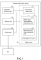
- FIG. 1 is a block diagram showing the main part configuration of the digital filter setting device 1.
- the digital filter setting device 1 includes a control part 10, an operation receiving part 20, the display part 30, and an output part 40.
- the control part 10 executes each processing in the digital filter setting device 1 including a processing for displaying the filter characteristics in the form of graph on the display part 30, and includes a parameter setting part (an input receiving part) 11 and a graph generating part (a graph display part) 12.
- the graph generating part 12 includes an attenuation characteristic calculation part (a filter characteristic calculation part) 13 and a step response time calculation part (a filter characteristic calculation part) 14.
- the parameter setting part 11 sets the filter parameters in the digital filter processing executed by the high-speed analog unit 5. More specifically, the parameter setting part 11 notifies the graph generating part 12 of values of the filter parameters received via the operation receiving part 20, and sets final filter parameter values decided by the user to be the filter parameters of the digital filter executed by the high-speed analog unit 5 by outputting the final filter parameter values via the output part 40.
- the filter parameters include a sampling cycle, a cut-off frequency of the low-pass filter, a moving-average count of the moving-average filter, and so on.
- the graph generating part 12 generates a graph showing the filter characteristics of the digital filter processing executed by the high-speed analog unit 5 using the filter parameters set by the parameter setting part 11, and displays the graph on the display part 30. More specifically, the graph generating part 12 includes the attenuation characteristic calculation part 13 and the step response time calculation part 14, generates a graph showing the attenuation characteristic calculated by the attenuation characteristic calculation part 13 and displays the graph on the display part 30, and generates a graph showing the step response time calculated by the step response time calculation part 14 and displays the graph on the display part 30. Besides, in the embodiment, although described as a configuration in which both the attenuation characteristic and the step response time are displayed, the invention is not limited thereto and may be configured to display any one of the two or may be configured to alternately display both.
- the attenuation characteristic calculation part 13 calculates the attenuation characteristic in the digital filter processing executed by the high-speed analog unit 5 using the filter parameters notified from the parameter setting part 11. Besides, the calculation processing of the attenuation characteristic is specifically described later.
- the step response time calculation part 14 calculates the step response time in the digital filter processing executed by the high-speed analog unit 5 using the filter parameters notified from the parameter setting part 11. Besides, the calculation processing of the step response time is specifically described later.
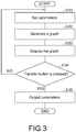
- FIG. 3 is a flowchart showing the processing flow of the digital filter setting device 1.
- the digital filter setting device 1 receives the setting of the filter parameters of the digital filter processing executed in the high-speed analog unit 5 (S101, an input receiving step).
- the graph generating part 12 calculates the filter characteristics of the digital filter in the set filter parameters, generates a graph showing the filter characteristics (S102, a filter characteristic calculation step) and displays the graph on the display part 30 (S103, a graph display step).
- step S105 when the button is pressed ("YES” in S104) and returns to step S101 when the button is not pressed ("NO” in S104).
- step S105 when the button is pressed
- step S101 when the button is not pressed
- the user can confirm whether the filter characteristics are desirable, for example, whether the step response time is within the sampling cycle and an attenuation effect is exhibited.
- the transfer button corresponding to "YES” in step S104
- sets the set filter parameters to be the parameters of the digital filter of the high-speed analog unit 5.
- step S104 when it is determined that there is a problem, the user does not press the transfer button and resets the filter parameters (corresponding to a flow from "NO" in step S104 to step S101). Accordingly, the setting of the filter parameters is repeated and finally the filter parameters by which a desired effect is exhibited can be obtained.
- step S105 by outputting the set filter parameters to the high-speed analog unit 5, the parameters of the digital filter processing executed by the high-speed analog unit 5 are set.
- the digital filter setting device 1 of the embodiment displays, in the form of graph, the filter characteristics (the step response time and the attenuation characteristic) of the digital filter used in the digital filter processing executed by the high-speed analog unit 5, and displays the task cycle of the fixed-cycle task executed by the PLC 2. Accordingly, the user can easily confirm whether the step response time is within the range of the task cycle.
- the analog value can be more stabilized when more digital filter processing is executed, and thus it is desirable that the digital filter processing is executed as much as possible.
- the more the digital filter processing is executed the longer the step response time is, resulting in the analog input value after the filter rising with a delay corresponding to the step response time.
- an I/O refresh timing of the PLC system bus 7 of the PLC 2 may be in the midway of the rising of the analog input value after the filter; in this case, the analog input value transmitted to the CPU unit 6 or the communication coupler 8 becomes a value in the midway of the rising.
- the user can easily confirm whether the step response time is within the range of the task cycle, and thus the user can easily confirm whether the above-described adverse effects occur. Therefore, the user can easily set the filter parameters and can execute an optimal digital filter processing in the high-speed analog unit 5 without the occurrence of the above-described adverse effects.
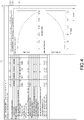
- FIG. 4 is a drawing showing the screen example of the digital filter setting device 1.
- a setting screen of the filter parameters of the digital filter used in the digital filter processing executed in the high-speed analog unit 5 and the filter characteristics of the digital filter in the setting are displayed.
- channels Ch1, Ch2, Ch3, Ch4
- channels a display area 303.
- the filter characteristics of this channel are displayed.
- the digital filter processing function that can be executed in the high-speed analog unit 5, that is, any one of a low-pass filter function, a moving-average filter function and a function combining the two can be selected (a display area 304).
- any one of graph type selection tabs shown on the display area 304 any one of the low-pass filter, the moving-average filter, and the combination of the low-pass filter and the moving-average filter can be selected, and the filter characteristics of the selected digital filter are displayed.
- a sampling number (time), a sampling cycle ( ⁇ s), a frequency (kHz), a cut-off frequency (Hz) of the low-pass filter, a moving-average count (time) of the moving-average filter, an operation cycle ( ⁇ s) of the digital filter, and an operation frequency (Hz) of the digital filter can be set.
- the graph showing the attenuation characteristic and the graph showing the step response time are displayed.
- the task cycle of the fixed-cycle task may be displayed. In the example shown in FIG. 4 , it is displayed on the upper part of the display area 301 that the task cycle of the fixed-cycle task is 1 ms.
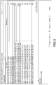
- FIG. 5 a screen example in which the finally decided filter parameters are set in the high-speed analog unit 5 is shown.
- a screen that can confirm the set filter parameters as shown in FIG. 5 is displayed.
- a "transfer (computer ⁇ unit)" button shown in FIG. 5 is pressed, the displayed filter parameters are output to the high-speed analog unit 5, and the filter parameters of the digital filter processing executed by the high-speed analog unit 5 are set.
- the digital filter setting device 1 acquires the filter parameters set at that point from the high-speed analog unit 5.
- the digital filter setting device 1 collates the filter parameters on a screen in the digital filter setting device 1 (that is, the filter parameters in the software for setting the filter parameters) and the filter parameters set by the high-speed analog unit 5, and performs a display demonstrating the filter parameters of different values.
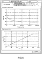
- FIGs. 6-8 are drawings showing examples of the filter characteristics displayed by the digital filter setting device 1.
- the filter characteristics the attenuation characteristic, the step response time
- FIG. 7 the filter characteristics (the attenuation characteristic, the step response time) in a case of using the low-pass filter as the digital filter are shown.
- FIG. 8 the filter characteristics (the attenuation characteristic, the step response time) in a case of using the combination of the low-pass filter and the moving-average filter as the digital filter are shown.
- the filter characteristics shown in FIG. 8 are filter characteristics in the case of using the combination of the low-pass filter and the moving-average filter as the digital filter, and thus is a sum of the filter characteristics in the case of using the moving-average filter shown in FIG. 6 and the filter characteristics in the case of using the low-pass filter shown in FIG. 7 .
- the filter characteristics shown in FIGs. 6-8 can be switched by selecting any one of the graph type selection tabs.
- the filter characteristics of the low-pass filter and the moving-average filter are displayed in the form of graph, the user can easily recognize the filter characteristics of each digital filter or the filter characteristics of the combination of both. Accordingly, in regard to each of the low-pass filter and the moving-average filter, the user can confirm a change degree of the characteristics resulted from the alteration of the parameters and thus can easily determine which parameter should be altered. In addition, a combined result is also displayed so that the user can also easily recognize the final characteristics resulted from the parameter alteration.
- a control block of the digital filter setting device 1 may be implemented by a logic circuit (hardware) formed in an integrated circuit (IC chip) and the like, or may be implemented by software.
- the digital filter setting device 1 is provided with a computer that executes commands of a program which is software for implementing each function.
- the computer includes, for example, one or more processor and a computer readable recording medium in which the above program is stored.
- the processor reads the program from the recording medium and executes the program in the computer, thereby achieving the purpose of the invention.
- a CPU Central Processing Unit
- a non-transitory tangible media such as a ROM (Read Only Storage) and the like, a tape, a disk, a card, a semiconductor memory, a programmable logic circuit and the like can be used as the above recording medium.
- a RAM Random Access Storage
- the program may be supplied to the computer via an optional transmission medium (a communication network or a broadcast wave or the like) capable of transmitting the program.
- an optional transmission medium a communication network or a broadcast wave or the like
- one aspect of the invention can also be implemented in a form of a data signal which is embedded in a carrier wave and in which the program is embodied by an electronic transmission.
Landscapes
- Engineering & Computer Science (AREA)
- Physics & Mathematics (AREA)
- Computer Hardware Design (AREA)
- Theoretical Computer Science (AREA)
- General Physics & Mathematics (AREA)
- Mathematical Physics (AREA)
- Automation & Control Theory (AREA)
- Computing Systems (AREA)
- Microelectronics & Electronic Packaging (AREA)
- Evolutionary Computation (AREA)
- Geometry (AREA)
- General Engineering & Computer Science (AREA)
- Programmable Controllers (AREA)
- Testing And Monitoring For Control Systems (AREA)
Abstract
Description
- The invention relates to a digital filter setting device which sets parameters of a digital filter and so on.
- A digital filter processing device which eliminates an electrical noise, a mechanical vibration noise and the like included in an analog input signal and stabilizes the analog signal by performing a digital filter processing to the analog input signal is known. In the digital filter processing device, the analog signal can be stabilized by executing multiple digital filter processing. However, the more the digital filter processing is, the longer the step response time is, resulting in a delay of rising of the analog signal after the digital filter processing.
- Therefore, it is desirable that a relation between parameters and the step response time or the like of the digital filter can be recognized in advance. However, so far, a user refers to a manual to calculate an operation cycle of the digital filter and performs parameter tuning of the digital filter when setting the parameters of the digital filter.
- Besides, for example, described in
patent literature 1 is a setting assistance device which assists in easily and appropriately setting a plurality of control parameters. In the setting assistance device described inpatent literature 1, a value of at least one of the control parameters is changed to perform a simulation using a virtual model and calculate a performance index of a control object. - In addition, a technology related to an optimal design assistance device for a feed drive system of a multi-spindle machine tool is described in
patent literature 2. In addition, an example of performing parameter input, a transient analysis processing, an AC analysis processing and a filter effect analysis processing in the simulation is described inpatent literature 3. -
- [Patent literature 1] Japanese Patent Application Laid-open No.
2017-167607 (disclosed on September 21, 2017 - [Patent literature 2] Japanese Patent Application Laid-open No.
2008-102714 (disclosed on May 1, 2008 - [Patent literature 3] Japanese Patent Application Laid-open No.
2014-182734 (disclosed on September 29, 2014 - As described above, it is desirable that a relation between parameters and a step response time or the like of a digital filter can be recognized in advance. However, in order to calculate the step response time, it is necessary to grasp a digital filter operation cycle and the like but a formula thereof is complex. Therefore, a user cannot easily calculate by using a manual and the like.
- When the step response time is long, rising of an input analog signal is delayed. Accordingly, for example, in a programmable logic controller (PLC), when an I/O refresh timing is in the midway of the rising of the input analog signal, the input analog signal transmitted to a CPU unit or a communication coupler becomes a value in the midway of the rising.
- In addition, the above-described
patent literature 1 does not support the setting of the digital filter. In addition, inpatent literatures - One aspect of the invention is accomplished based on the above problems, and aims to realize a digital filter setting device or the like by which the filter characteristics of the digital filter after the parameter setting can be easily recognized by the user.
- In order to solve the above problems, the digital filter setting device of one aspect of the invention is a digital filter setting device which sets filter parameters of a digital filter device that performs a filter processing to an input analog signal by a digital filter, and the digital filter setting device includes: an input receiving part receiving input of the filter parameters; a filter characteristic calculation part calculating a step response time as a filter characteristic of the digital filter in a case that the filter parameters received by the input receiving part are set; and a graph display part displaying the calculated step response time in the form of graph on a display part.
- According to the configuration, the step response time of the digital filter in a case of using the set filter parameters is displayed in the form of graph. Therefore, the user can recognize immediately the step response time of the digital filter in a case of using the filter parameters set by himself.
- Accordingly, the user can easily recognize whether, at the step response time of the digital filter to which the filter parameters are set, rising of the analog signal after the filtering is delayed and an I/O refresh timing comes in the midway of the rising, for example, whether the analog signal transmitted to a CPU unit or a communication master which is an output destination becomes a value in the midway of the rising. Therefore, it can be prevented that the I/O refresh timing is in the midway of the rising of the analog signal and the analog input value transmitted to the CPU unit or the communication master becomes a value in the midway of the rising.
- The digital filter setting device of one aspect of the invention is included in a control device which controls a control object by repeatedly executing a plurality of control programs at a prescribed time interval, and the graph display part may cause a task cycle of a fixed-cycle task in the control device to be displayed along with the graph on the display part.
- According to the aforementioned configuration, the task cycle is displayed, and thus the user can easily recognize whether the step response time is within the task cycle.
- In the digital filter setting device of one aspect of the invention, the filter characteristic calculation part calculates an attenuation characteristic of the digital filter as the filter characteristic, and the graph display part may display the attenuation characteristic of the digital filter in the form of graph.
- According to the aforementioned configuration, the attenuation characteristic of the digital filter is displayed in the form of graph and thus the user can easily recognize the attenuation characteristic of the digital filter. Therefore, the user can confirm whether a change of the attenuation characteristic associated with parameter alteration is in a desired state.
- The digital filter setting device of one aspect of the invention is capable of processing using plural kinds of digital filters, and the graph display part may display, in the form of graph, the filter characteristics of each of the plural kinds of digital filters or the filter characteristics in a combination of the plural kinds of digital filters.
- According to the aforementioned configuration, the filter characteristics of the plural kinds of digital filters are displayed in the form of graph, and thus the user can easily recognize the filter characteristic of each digital filter or the filter characteristic of the combination of the digital filters. Therefore, the user can recognize a change degree of characteristics resulted from parameter alteration for each kind of the digital filters and thus can easily determine which parameter should be altered. In addition, a combined result is also displayed and thus the user can also easily recognize a final characteristic resulted from the parameter alteration.
- In the digital filter setting device of one aspect of the invention, the filter parameters may include a cut-off frequency in a low-pass filter and a moving-average count in a moving-average filter.
- According to the aforementioned configuration, the user can easily recognize the filter characteristics corresponding to the cut-off frequency in the low-pass filter and the moving-average count in the moving-average filter.
- In order to solve the above problems, the control method of the digital filter setting device of one aspect of the invention is a control method of the digital filter setting device which sets filter parameters of a digital filter device for performing a filtering on an input analog signal by using a digital filter, and the control method of the digital filter setting device includes: an input receiving step for receiving input of the filter parameters; a filter characteristic calculation step for calculating a step response time as a filter characteristic of the digital filter in a case that the filter parameters received in the input receiving step are set; and a graph display step for displaying the calculated step response time in the form of graph on a display part.
- According to the above method, the same effect as the above-described effect is exhibited.
- The digital filter setting device of each aspect of the invention may be implemented by a computer; in this case, a control program of the digital filter setting device which implements the digital filter setting device with the computer by causing the computer to operate as each part (a software element) provided in the digital filter setting device, and a computer readable recording medium for recording the control program also fall into the range of the invention.
- According to one aspect of the invention, the step response time of the digital filter in a case of using the set filter parameters is displayed in the form of graph. Therefore, an effect is exhibited that the user can recognize immediately the step response time of the digital filter in a case of using the filter parameters set by himself.
-
-
FIG. 1 is a block diagram showing a main part configuration of a digital filter setting device of an embodiment of the invention. -
FIG. 2 is a drawing schematically showing an example of a control system including the digital filter setting device. -
FIG. 3 is a flowchart showing a processing flow in the digital filter setting device. -
FIG. 4 is a drawing showing a screen example of the digital filter setting device. -
FIG. 5 is a drawing showing a screen example in which filter parameters finally decided by a user are set in a high-speed analog unit. -
FIG. 6 is a drawing showing an example of filter characteristics displayed by the digital filter setting device. -
FIG. 7 is a drawing showing an example of filter characteristics displayed by the digital filter setting device. -
FIG. 8 is a drawing showing an example of filter characteristics displayed by the digital filter setting device. - At first, with reference to
FIG. 2 , an example of a scene in which the invention is applied is described.FIG. 2 is a drawing schematically showing an example of a control system including a digitalfilter setting device 1 of the embodiment. As shown inFIG. 2 , in the control system of the embodiment, in addition to the above-described digitalfilter setting device 1, a PLC (programmable logic controller) 2, anIO terminal 3 and adisplay input device 4 are included; the digitalfilter setting device 1, thePLC 2 and thedisplay input device 4 are connected via a network, and thePLC 2 and theIO terminal 3 are also connected via a network. - Besides, as shown by a dotted line in
FIG. 2 , the digitalfilter setting device 1 and acommunication coupler 8 of theIO terminal 3 may be directly connected, for example, by a USB (universal serial bus) cable and so on. - The digital
filter setting device 1 is a device connected to a control system and used for setting the filter parameters of a digital filter processing in a high-speed analog unit (digital filter device) 5. An information processing device such as a computer may be used as the digitalfilter setting device 1, or a portable information processing device such as a notebook computer may be used. - The
PLC 2 is a control device which controls a control object such as machinery and equipment, and controls the control object by repeatedly executing a plurality of control programs at a prescribed time interval. ThePLC 2 is provided with aCPU unit 6 performing main operation processing and the high-speed analog unit 5, and the units in thePLC 2 are configured in a manner that data can be exchanged therebetween by aPLC system bus 7. - The high-
speed analog unit 5 is a unit capable of performing a digital filter processing on an input analog signal and outputting the analog signal. The digital filter processing that can be executed by the high-speed analog unit 5 includes a processing using a low-pass filter, a processing using a moving-average filter, and a process using a combination of these filters. In the high-speed analog unit 5, by performing the digital filter processing on the input analog signal, noise components (electrical noise and mechanical vibration noise) included in the analog signal can be eliminated and a fluctuation of the analog input value can be suppressed, and the analog signal can be stabilized. - In addition, although not shown in the drawings, an input and output apparatus controlled by the
PLC 2 may be connected to the high-speed analog unit 5. The input and output apparatus includes, for example, a "detector" such as a temperature sensor, an optical sensor or the like, an input apparatus such as a "switch (a push-button switch, a limit switch, a pressure switch or the like)", and an output apparatus such as a "actuator", a "relay", a "solenoid valve", a "display" and a "display lamp". - The
IO terminal 3 includes thecommunication coupler 8 and the high-speed analog unit 5 for performing a processing related to data transmission. Thecommunication coupler 8 and the high-speed analog unit 5 are configured to be capable of reciprocally exchanging data via anIO terminal bus 9. - The
display input device 4 operates thePLC 2, confirms an operation state of the control system, and so on. Thedisplay input device 4 may be, for example, of a touch-panel type. In addition, thedisplay input device 4 may function as the digitalfilter setting device 1. - As described above, in the embodiment, the setting of the filter parameters in the digital filter processing executed by the high-
speed analog unit 5 is performed by the digitalfilter setting device 1. Besides, in the digitalfilter setting device 1, the filter characteristics (a step response time and an attenuation characteristic) of the digital filter in the set filter parameters are displayed in the form of graph on adisplay part 30 of the digitalfilter setting device 1. Accordingly, the user can recognize immediately whether the set filter parameters are appropriate by confirming the graph of filter characteristics. Therefore, the filter characteristics of the digital filter after the filter parameter setting can be easily recognized by the user. - Next, with reference to
FIG. 1 , a main part configuration of the digitalfilter setting device 1 is described.FIG. 1 is a block diagram showing the main part configuration of the digitalfilter setting device 1. As shown inFIG. 1 , the digitalfilter setting device 1 includes acontrol part 10, anoperation receiving part 20, thedisplay part 30, and anoutput part 40. - The
control part 10 executes each processing in the digitalfilter setting device 1 including a processing for displaying the filter characteristics in the form of graph on thedisplay part 30, and includes a parameter setting part (an input receiving part) 11 and a graph generating part (a graph display part) 12. In addition, thegraph generating part 12 includes an attenuation characteristic calculation part (a filter characteristic calculation part) 13 and a step response time calculation part (a filter characteristic calculation part) 14. - The
parameter setting part 11 sets the filter parameters in the digital filter processing executed by the high-speed analog unit 5. More specifically, theparameter setting part 11 notifies thegraph generating part 12 of values of the filter parameters received via theoperation receiving part 20, and sets final filter parameter values decided by the user to be the filter parameters of the digital filter executed by the high-speed analog unit 5 by outputting the final filter parameter values via theoutput part 40. The filter parameters include a sampling cycle, a cut-off frequency of the low-pass filter, a moving-average count of the moving-average filter, and so on. - The
graph generating part 12 generates a graph showing the filter characteristics of the digital filter processing executed by the high-speed analog unit 5 using the filter parameters set by theparameter setting part 11, and displays the graph on thedisplay part 30. More specifically, thegraph generating part 12 includes the attenuationcharacteristic calculation part 13 and the step responsetime calculation part 14, generates a graph showing the attenuation characteristic calculated by the attenuationcharacteristic calculation part 13 and displays the graph on thedisplay part 30, and generates a graph showing the step response time calculated by the step responsetime calculation part 14 and displays the graph on thedisplay part 30. Besides, in the embodiment, although described as a configuration in which both the attenuation characteristic and the step response time are displayed, the invention is not limited thereto and may be configured to display any one of the two or may be configured to alternately display both. - The attenuation
characteristic calculation part 13 calculates the attenuation characteristic in the digital filter processing executed by the high-speed analog unit 5 using the filter parameters notified from theparameter setting part 11. Besides, the calculation processing of the attenuation characteristic is specifically described later. - The step response
time calculation part 14 calculates the step response time in the digital filter processing executed by the high-speed analog unit 5 using the filter parameters notified from theparameter setting part 11. Besides, the calculation processing of the step response time is specifically described later. - Next, with reference to
FIG. 3 , a processing flow of the digitalfilter setting device 1 is described.FIG. 3 is a flowchart showing the processing flow of the digitalfilter setting device 1. As shown inFIG. 3 , first, the digitalfilter setting device 1 receives the setting of the filter parameters of the digital filter processing executed in the high-speed analog unit 5 (S101, an input receiving step). Next, thegraph generating part 12 calculates the filter characteristics of the digital filter in the set filter parameters, generates a graph showing the filter characteristics (S102, a filter characteristic calculation step) and displays the graph on the display part 30 (S103, a graph display step). - Next, in the digital
filter setting device 1, it is determined whether a transfer button is pressed (SI04), and the processing proceeds to step S105 when the button is pressed ("YES" in S104) and returns to step S101 when the button is not pressed ("NO" in S104). This means the following situation. By the display of the graph of the filter characteristics in step S103, the user can confirm whether the filter characteristics are desirable, for example, whether the step response time is within the sampling cycle and an attenuation effect is exhibited. When it is determined that there is no problem as a result of the confirmation, the user presses the transfer button (corresponding to "YES" in step S104) and sets the set filter parameters to be the parameters of the digital filter of the high-speed analog unit 5. On the other hand, when it is determined that there is a problem, the user does not press the transfer button and resets the filter parameters (corresponding to a flow from "NO" in step S104 to step S101). Accordingly, the setting of the filter parameters is repeated and finally the filter parameters by which a desired effect is exhibited can be obtained. - In step S105, by outputting the set filter parameters to the high-
speed analog unit 5, the parameters of the digital filter processing executed by the high-speed analog unit 5 are set. - As described above, the digital
filter setting device 1 of the embodiment displays, in the form of graph, the filter characteristics (the step response time and the attenuation characteristic) of the digital filter used in the digital filter processing executed by the high-speed analog unit 5, and displays the task cycle of the fixed-cycle task executed by thePLC 2. Accordingly, the user can easily confirm whether the step response time is within the range of the task cycle. - The analog value can be more stabilized when more digital filter processing is executed, and thus it is desirable that the digital filter processing is executed as much as possible. However, the more the digital filter processing is executed, the longer the step response time is, resulting in the analog input value after the filter rising with a delay corresponding to the step response time.
- Therefore, for example, an I/O refresh timing of the
PLC system bus 7 of thePLC 2 may be in the midway of the rising of the analog input value after the filter; in this case, the analog input value transmitted to theCPU unit 6 or thecommunication coupler 8 becomes a value in the midway of the rising. - As described above, according to the embodiment, the user can easily confirm whether the step response time is within the range of the task cycle, and thus the user can easily confirm whether the above-described adverse effects occur. Therefore, the user can easily set the filter parameters and can execute an optimal digital filter processing in the high-
speed analog unit 5 without the occurrence of the above-described adverse effects. - Next, with reference to
FIG. 4 , a screen example displayed on thedisplay part 30 of the digitalfilter setting device 1 is described.FIG. 4 is a drawing showing the screen example of the digitalfilter setting device 1. - As shown in
FIG. 4 , on thedisplay part 30 of the digitalfilter setting device 1, a setting screen of the filter parameters of the digital filter used in the digital filter processing executed in the high-speed analog unit 5 and the filter characteristics of the digital filter in the setting are displayed. - In the example shown in
FIG. 4 , firstly, four channels (Ch1, Ch2, Ch3, Ch4) can be set as channels (a display area 303). By selecting any one of Ch1, Ch2, Ch3 and Ch4 in channel selection tabs shown on thedisplay area 303, the filter characteristics of this channel are displayed. - In addition, the digital filter processing function that can be executed in the high-
speed analog unit 5, that is, any one of a low-pass filter function, a moving-average filter function and a function combining the two can be selected (a display area 304). By selecting any one of graph type selection tabs shown on thedisplay area 304, any one of the low-pass filter, the moving-average filter, and the combination of the low-pass filter and the moving-average filter can be selected, and the filter characteristics of the selected digital filter are displayed. - In addition, as shown on the
display area 301, as the filter parameters, a sampling number (time), a sampling cycle (µs), a frequency (kHz), a cut-off frequency (Hz) of the low-pass filter, a moving-average count (time) of the moving-average filter, an operation cycle (µs) of the digital filter, and an operation frequency (Hz) of the digital filter can be set. - Furthermore, on the
display area 302, as the filter characteristics of the digital filter, the graph showing the attenuation characteristic and the graph showing the step response time are displayed. - In addition, the task cycle of the fixed-cycle task may be displayed. In the example shown in
FIG. 4 , it is displayed on the upper part of thedisplay area 301 that the task cycle of the fixed-cycle task is 1 ms. - In
FIG. 5 , a screen example in which the finally decided filter parameters are set in the high-speed analog unit 5 is shown. When the user who has confirmed the filter characteristics shown inFIG. 4 determines that there is no problem and the filter parameters are decided, a screen that can confirm the set filter parameters as shown inFIG. 5 is displayed. Then, when a "transfer (computer→unit)" button shown inFIG. 5 is pressed, the displayed filter parameters are output to the high-speed analog unit 5, and the filter parameters of the digital filter processing executed by the high-speed analog unit 5 are set. - In addition, when a "transfer (unit→computer)" button is pressed, the digital
filter setting device 1 acquires the filter parameters set at that point from the high-speed analog unit 5. - In addition, when a "collation" button is pressed, the digital
filter setting device 1 collates the filter parameters on a screen in the digital filter setting device 1 (that is, the filter parameters in the software for setting the filter parameters) and the filter parameters set by the high-speed analog unit 5, and performs a display demonstrating the filter parameters of different values. - Next, with reference to
FIGs. 6-8 , a display example of filter characteristics is described.FIGs. 6-8 are drawings showing examples of the filter characteristics displayed by the digitalfilter setting device 1. InFIG. 6 , the filter characteristics (the attenuation characteristic, the step response time) in a case of using the moving-average filter as the digital filter are shown. InFIG. 7 , the filter characteristics (the attenuation characteristic, the step response time) in a case of using the low-pass filter as the digital filter are shown. In addition, inFIG. 8 , the filter characteristics (the attenuation characteristic, the step response time) in a case of using the combination of the low-pass filter and the moving-average filter as the digital filter are shown. - The filter characteristics shown in
FIG. 8 are filter characteristics in the case of using the combination of the low-pass filter and the moving-average filter as the digital filter, and thus is a sum of the filter characteristics in the case of using the moving-average filter shown inFIG. 6 and the filter characteristics in the case of using the low-pass filter shown inFIG. 7 . - In addition, as described above, the filter characteristics shown in
FIGs. 6-8 can be switched by selecting any one of the graph type selection tabs. - According to this configuration, since the filter characteristics of the low-pass filter and the moving-average filter are displayed in the form of graph, the user can easily recognize the filter characteristics of each digital filter or the filter characteristics of the combination of both. Accordingly, in regard to each of the low-pass filter and the moving-average filter, the user can confirm a change degree of the characteristics resulted from the alteration of the parameters and thus can easily determine which parameter should be altered. In addition, a combined result is also displayed so that the user can also easily recognize the final characteristics resulted from the parameter alteration.
- A control block of the digital filter setting device 1 (especially the control part 10 (the
parameter setting part 11, thegraph generating part 12, the attenuationcharacteristic calculation part 13, and the step response time calculation part 14)) may be implemented by a logic circuit (hardware) formed in an integrated circuit (IC chip) and the like, or may be implemented by software. - In the latter case, the digital
filter setting device 1 is provided with a computer that executes commands of a program which is software for implementing each function. The computer includes, for example, one or more processor and a computer readable recording medium in which the above program is stored. Besides, the processor reads the program from the recording medium and executes the program in the computer, thereby achieving the purpose of the invention. A CPU (Central Processing Unit) for example can be used as the processor. In addition to a "non-transitory tangible media" such as a ROM (Read Only Storage) and the like, a tape, a disk, a card, a semiconductor memory, a programmable logic circuit and the like can be used as the above recording medium. Besides, a RAM (Random Access Storage) and the like for deploying the program may be further provided. In addition, the program may be supplied to the computer via an optional transmission medium (a communication network or a broadcast wave or the like) capable of transmitting the program. Furthermore, one aspect of the invention can also be implemented in a form of a data signal which is embedded in a carrier wave and in which the program is embodied by an electronic transmission. -
- 1 digital filter setting device
- 2 PLC (control device)
- 3 IO terminal
- 4 display input device
- 5 high-speed analog unit (digital filter device)
- 6 CPU unit
- 7 PLC system bus
- 8 communication coupler
- 9 IO terminal bus
- 10 control part
- 11 parameter setting part (input receiving part)
- 12 graph generating part (graph display part)
- 13 attenuation characteristic calculation part (filter characteristic calculation part)
- 14 step response time calculation part (filter characteristic calculation part)
- 20 operation receiving part
- 30 display part
- 40 output part
Claims (7)
- A digital filter setting device (1) which sets filter parameters of a digital filter device (5) that performs a filter processing to an input analog signal by a digital filter, characterized in that, the digital filter setting device (1) comprises:an input receiving part (11) receiving input of the filter parameters;a filter characteristic calculation part (14) calculating a step response time as a filter characteristic of the digital filter when the filter parameters received by the input receiving part (11) are set; anda graph display part (12) displaying the calculated step response time in a form of graph on a display part.
- The digital filter setting device (1) according to claim 1, wherein the digital filter device (5) is included in a control device which controls a control object by repeatedly executing a plurality of control programs at a prescribed time interval, and
the graph display part (12) causes a task cycle of a fixed-cycle task in the control device to be displayed along with the graph on the display part. - The digital filter setting device (1) according to claim 1 or 2, wherein the filter characteristic calculation part (14) calculates an attenuation characteristic of the digital filter as the filter characteristic, and
the graph display part (12) displays the attenuation characteristic of the digital filter in the form of graph. - The digital filter setting device (1) according to any one of claims 1 to 3, wherein the digital filter device (5) comprises executing processing of plural kinds of digital filters, and
the graph display part (12) displays, in the form of graph, the filter characteristics of each of the plural kinds of digital filters or the filter characteristics in a combination of the plural kinds of digital filters. - The digital filter setting device (1) according to any one of claims 1 to 4, wherein the filter parameters comprise a cut-off frequency in a low-pass filter and a moving-average count in a moving-average filter.
- A control method of a digital filter setting device (1) which sets filter parameters of a digital filter device (5) for performing a filter processing to an input analog signal by the digital filter, characterized in that, the control method comprises:an input receiving step for receiving input of the filter parameters;a filter characteristic calculation step for calculating a step response time as a filter characteristic of the digital filter when the filter parameters received by the input receiving part (11) are set; anda graph display step for displaying the calculated step response time in a form of graph on a display part.
- A control program, characterized in that, the control program causes a computer to function as the digital filter setting device (1) according to claim 1 and causes the computer to function as the filter characteristic calculation part (14) and the graph display part (12).
Applications Claiming Priority (1)
| Application Number | Priority Date | Filing Date | Title |
|---|---|---|---|
| JP2018042113A JP6939652B2 (en) | 2018-03-08 | 2018-03-08 | Digital filter setting device, control method of digital filter setting device, and control program |
Publications (2)
| Publication Number | Publication Date |
|---|---|
| EP3537242A1 true EP3537242A1 (en) | 2019-09-11 |
| EP3537242B1 EP3537242B1 (en) | 2020-04-01 |
Family
ID=64901320
Family Applications (1)
| Application Number | Title | Priority Date | Filing Date |
|---|---|---|---|
| EP18212224.2A Active EP3537242B1 (en) | 2018-03-08 | 2018-12-13 | Digital filter setting device, control method of digital filter setting device and control program |
Country Status (4)
| Country | Link |
|---|---|
| US (1) | US20190280673A1 (en) |
| EP (1) | EP3537242B1 (en) |
| JP (1) | JP6939652B2 (en) |
| CN (1) | CN110245369B (en) |
Families Citing this family (1)
| Publication number | Priority date | Publication date | Assignee | Title |
|---|---|---|---|---|
| JP2023136039A (en) * | 2022-03-16 | 2023-09-29 | 株式会社イシダ | Weighing device |
Citations (4)
| Publication number | Priority date | Publication date | Assignee | Title |
|---|---|---|---|---|
| JP2008102714A (en) | 2006-10-18 | 2008-05-01 | Tokyo Univ Of Agriculture & Technology | Optimal design support device for feed drive system of multi-axis machine tool and program for the device |
| US20140137069A1 (en) * | 2012-11-09 | 2014-05-15 | Analog Devices, Inc. | Filter design tool |
| JP2014182734A (en) | 2013-03-21 | 2014-09-29 | Renesas Electronics Corp | Simulator, simulation method and simulation program for semiconductor device |
| JP2017167607A (en) | 2016-03-14 | 2017-09-21 | オムロン株式会社 | Setting support apparatus, setting support method, information processing program, and record medium |
Family Cites Families (9)
| Publication number | Priority date | Publication date | Assignee | Title |
|---|---|---|---|---|
| GB1523729A (en) * | 1975-11-20 | 1978-09-06 | Avery Ltd W & T | Digital filtering |
| JP2001255932A (en) * | 2000-03-14 | 2001-09-21 | Yokogawa Electric Corp | Device for identifying process constant |
| JP2003243967A (en) * | 2002-02-20 | 2003-08-29 | Matsushita Electric Ind Co Ltd | Digital filter coefficient setting apparatus and method |
| JP4060148B2 (en) * | 2002-08-23 | 2008-03-12 | 本田技研工業株式会社 | Plant control equipment |
| JP2005242522A (en) * | 2004-02-25 | 2005-09-08 | Kanto Auto Works Ltd | Cycle time measurement device for sequence controller |
| US7206722B2 (en) * | 2005-04-01 | 2007-04-17 | Tektronix, Inc. | Oscilloscope having an enhancement filter |
| CA2603916A1 (en) * | 2005-04-04 | 2006-10-12 | Fisher-Rosemount Systems, Inc. | Statistical processing methods used in abnormal situation detection |
| US8301676B2 (en) * | 2007-08-23 | 2012-10-30 | Fisher-Rosemount Systems, Inc. | Field device with capability of calculating digital filter coefficients |
| KR101565286B1 (en) * | 2012-11-01 | 2015-11-02 | 미쓰비시덴키 가부시키가이샤 | Conversion device, peripheral device and programmable controller |
-
2018
- 2018-03-08 JP JP2018042113A patent/JP6939652B2/en active Active
- 2018-12-11 CN CN201811508698.2A patent/CN110245369B/en active Active
- 2018-12-13 EP EP18212224.2A patent/EP3537242B1/en active Active
- 2018-12-18 US US16/223,115 patent/US20190280673A1/en not_active Abandoned
Patent Citations (4)
| Publication number | Priority date | Publication date | Assignee | Title |
|---|---|---|---|---|
| JP2008102714A (en) | 2006-10-18 | 2008-05-01 | Tokyo Univ Of Agriculture & Technology | Optimal design support device for feed drive system of multi-axis machine tool and program for the device |
| US20140137069A1 (en) * | 2012-11-09 | 2014-05-15 | Analog Devices, Inc. | Filter design tool |
| JP2014182734A (en) | 2013-03-21 | 2014-09-29 | Renesas Electronics Corp | Simulator, simulation method and simulation program for semiconductor device |
| JP2017167607A (en) | 2016-03-14 | 2017-09-21 | オムロン株式会社 | Setting support apparatus, setting support method, information processing program, and record medium |
Also Published As
| Publication number | Publication date |
|---|---|
| US20190280673A1 (en) | 2019-09-12 |
| JP6939652B2 (en) | 2021-09-22 |
| CN110245369A (en) | 2019-09-17 |
| CN110245369B (en) | 2023-06-13 |
| EP3537242B1 (en) | 2020-04-01 |
| JP2019159483A (en) | 2019-09-19 |
Similar Documents
| Publication | Publication Date | Title |
|---|---|---|
| CN101815177B (en) | Synchronous displaying device, synchronous displaying method and superposition splice displaying system | |
| JP5265576B2 (en) | Control and / or data transmission module | |
| EP2511778B1 (en) | Input module for an industrial controller | |
| CN101231520B (en) | Method and apparatus for generating a schedule for performing functions in a process control system | |
| US9529351B2 (en) | System and method for parameterizing field devices of an automation or control system | |
| EP3474136A1 (en) | Method and apparatus for use in converting building block programming into program code | |
| EP1586966A2 (en) | Control system configuration device | |
| US20100082869A1 (en) | Stackable i/o modules appearing as standard usb mass storage devices | |
| JP5680259B2 (en) | Conversion device, peripheral device, and programmable controller | |
| EP3258329B1 (en) | Programmable logic controller, method for controlling programmable logic controller, and control program | |
| EP3258328B1 (en) | Plc control data generation device, plc control data generation method, and plc control data generation program | |
| TWI585556B (en) | Intelligent functional module and programmable logic controller system | |
| KR20130085810A (en) | Analog input module | |
| JP2012099063A (en) | Monitoring controller | |
| WO2015136960A1 (en) | Controller | |
| CN103916796A (en) | Dynamic speaker management for multichannel audio systems | |
| EP3537242B1 (en) | Digital filter setting device, control method of digital filter setting device and control program | |
| CN103905410A (en) | Multi-channel communication protocol converter capable of converting user-defined protocol to Modbus protocol | |
| JP2019144956A (en) | I/o management device | |
| EP3416004A1 (en) | Device management apparatus, device management method, device management program, and non-transitory computer readable storage medium | |
| CN106384723A (en) | Heat treatment equipment process control device and heat treatment equipment process control method with multiple main process steps | |
| CN111596573A (en) | Analog quantity processing method and system and automatic processing device | |
| CN105491183A (en) | Electronic equipment | |
| CN104376846A (en) | Voice adjusting method and device and electronic devices | |
| EP3961970A1 (en) | Serial data communication device |
Legal Events
| Date | Code | Title | Description |
|---|---|---|---|
| PUAI | Public reference made under article 153(3) epc to a published international application that has entered the european phase |
Free format text: ORIGINAL CODE: 0009012 |
|
| STAA | Information on the status of an ep patent application or granted ep patent |
Free format text: STATUS: REQUEST FOR EXAMINATION WAS MADE |
|
| 17P | Request for examination filed |
Effective date: 20190218 |
|
| AK | Designated contracting states |
Kind code of ref document: A1 Designated state(s): AL AT BE BG CH CY CZ DE DK EE ES FI FR GB GR HR HU IE IS IT LI LT LU LV MC MK MT NL NO PL PT RO RS SE SI SK SM TR |
|
| AX | Request for extension of the european patent |
Extension state: BA ME |
|
| GRAP | Despatch of communication of intention to grant a patent |
Free format text: ORIGINAL CODE: EPIDOSNIGR1 |
|
| STAA | Information on the status of an ep patent application or granted ep patent |
Free format text: STATUS: GRANT OF PATENT IS INTENDED |
|
| INTG | Intention to grant announced |
Effective date: 20191118 |
|
| RBV | Designated contracting states (corrected) |
Designated state(s): AL AT BE BG CH CY CZ DE DK EE ES FI FR GB GR HR HU IE IS IT LI LT LU LV MC MK MT NL NO PL PT RO RS SE SI SK SM TR |
|
| GRAS | Grant fee paid |
Free format text: ORIGINAL CODE: EPIDOSNIGR3 |
|
| GRAA | (expected) grant |
Free format text: ORIGINAL CODE: 0009210 |
|
| STAA | Information on the status of an ep patent application or granted ep patent |
Free format text: STATUS: THE PATENT HAS BEEN GRANTED |
|
| AK | Designated contracting states |
Kind code of ref document: B1 Designated state(s): AL AT BE BG CH CY CZ DE DK EE ES FI FR GB GR HR HU IE IS IT LI LT LU LV MC MK MT NL NO PL PT RO RS SE SI SK SM TR |
|
| REG | Reference to a national code |
Ref country code: GB Ref legal event code: FG4D |
|
| REG | Reference to a national code |
Ref country code: AT Ref legal event code: REF Ref document number: 1252172 Country of ref document: AT Kind code of ref document: T Effective date: 20200415 Ref country code: CH Ref legal event code: EP |
|
| REG | Reference to a national code |
Ref country code: DE Ref legal event code: R096 Ref document number: 602018003445 Country of ref document: DE |
|
| REG | Reference to a national code |
Ref country code: IE Ref legal event code: FG4D |
|
| PG25 | Lapsed in a contracting state [announced via postgrant information from national office to epo] |
Ref country code: BG Free format text: LAPSE BECAUSE OF FAILURE TO SUBMIT A TRANSLATION OF THE DESCRIPTION OR TO PAY THE FEE WITHIN THE PRESCRIBED TIME-LIMIT Effective date: 20200701 |
|
| REG | Reference to a national code |
Ref country code: NL Ref legal event code: MP Effective date: 20200401 |
|
| REG | Reference to a national code |
Ref country code: LT Ref legal event code: MG4D |
|
| PG25 | Lapsed in a contracting state [announced via postgrant information from national office to epo] |
Ref country code: FI Free format text: LAPSE BECAUSE OF FAILURE TO SUBMIT A TRANSLATION OF THE DESCRIPTION OR TO PAY THE FEE WITHIN THE PRESCRIBED TIME-LIMIT Effective date: 20200401 Ref country code: NO Free format text: LAPSE BECAUSE OF FAILURE TO SUBMIT A TRANSLATION OF THE DESCRIPTION OR TO PAY THE FEE WITHIN THE PRESCRIBED TIME-LIMIT Effective date: 20200701 Ref country code: GR Free format text: LAPSE BECAUSE OF FAILURE TO SUBMIT A TRANSLATION OF THE DESCRIPTION OR TO PAY THE FEE WITHIN THE PRESCRIBED TIME-LIMIT Effective date: 20200702 Ref country code: IS Free format text: LAPSE BECAUSE OF FAILURE TO SUBMIT A TRANSLATION OF THE DESCRIPTION OR TO PAY THE FEE WITHIN THE PRESCRIBED TIME-LIMIT Effective date: 20200801 Ref country code: CZ Free format text: LAPSE BECAUSE OF FAILURE TO SUBMIT A TRANSLATION OF THE DESCRIPTION OR TO PAY THE FEE WITHIN THE PRESCRIBED TIME-LIMIT Effective date: 20200401 Ref country code: NL Free format text: LAPSE BECAUSE OF FAILURE TO SUBMIT A TRANSLATION OF THE DESCRIPTION OR TO PAY THE FEE WITHIN THE PRESCRIBED TIME-LIMIT Effective date: 20200401 Ref country code: LT Free format text: LAPSE BECAUSE OF FAILURE TO SUBMIT A TRANSLATION OF THE DESCRIPTION OR TO PAY THE FEE WITHIN THE PRESCRIBED TIME-LIMIT Effective date: 20200401 Ref country code: PT Free format text: LAPSE BECAUSE OF FAILURE TO SUBMIT A TRANSLATION OF THE DESCRIPTION OR TO PAY THE FEE WITHIN THE PRESCRIBED TIME-LIMIT Effective date: 20200817 Ref country code: SE Free format text: LAPSE BECAUSE OF FAILURE TO SUBMIT A TRANSLATION OF THE DESCRIPTION OR TO PAY THE FEE WITHIN THE PRESCRIBED TIME-LIMIT Effective date: 20200401 |
|
| REG | Reference to a national code |
Ref country code: AT Ref legal event code: MK05 Ref document number: 1252172 Country of ref document: AT Kind code of ref document: T Effective date: 20200401 |
|
| PG25 | Lapsed in a contracting state [announced via postgrant information from national office to epo] |
Ref country code: RS Free format text: LAPSE BECAUSE OF FAILURE TO SUBMIT A TRANSLATION OF THE DESCRIPTION OR TO PAY THE FEE WITHIN THE PRESCRIBED TIME-LIMIT Effective date: 20200401 Ref country code: HR Free format text: LAPSE BECAUSE OF FAILURE TO SUBMIT A TRANSLATION OF THE DESCRIPTION OR TO PAY THE FEE WITHIN THE PRESCRIBED TIME-LIMIT Effective date: 20200401 Ref country code: LV Free format text: LAPSE BECAUSE OF FAILURE TO SUBMIT A TRANSLATION OF THE DESCRIPTION OR TO PAY THE FEE WITHIN THE PRESCRIBED TIME-LIMIT Effective date: 20200401 |
|
| PG25 | Lapsed in a contracting state [announced via postgrant information from national office to epo] |
Ref country code: AL Free format text: LAPSE BECAUSE OF FAILURE TO SUBMIT A TRANSLATION OF THE DESCRIPTION OR TO PAY THE FEE WITHIN THE PRESCRIBED TIME-LIMIT Effective date: 20200401 |
|
| REG | Reference to a national code |
Ref country code: DE Ref legal event code: R097 Ref document number: 602018003445 Country of ref document: DE |
|
| PG25 | Lapsed in a contracting state [announced via postgrant information from national office to epo] |
Ref country code: DK Free format text: LAPSE BECAUSE OF FAILURE TO SUBMIT A TRANSLATION OF THE DESCRIPTION OR TO PAY THE FEE WITHIN THE PRESCRIBED TIME-LIMIT Effective date: 20200401 Ref country code: EE Free format text: LAPSE BECAUSE OF FAILURE TO SUBMIT A TRANSLATION OF THE DESCRIPTION OR TO PAY THE FEE WITHIN THE PRESCRIBED TIME-LIMIT Effective date: 20200401 Ref country code: SM Free format text: LAPSE BECAUSE OF FAILURE TO SUBMIT A TRANSLATION OF THE DESCRIPTION OR TO PAY THE FEE WITHIN THE PRESCRIBED TIME-LIMIT Effective date: 20200401 Ref country code: AT Free format text: LAPSE BECAUSE OF FAILURE TO SUBMIT A TRANSLATION OF THE DESCRIPTION OR TO PAY THE FEE WITHIN THE PRESCRIBED TIME-LIMIT Effective date: 20200401 Ref country code: ES Free format text: LAPSE BECAUSE OF FAILURE TO SUBMIT A TRANSLATION OF THE DESCRIPTION OR TO PAY THE FEE WITHIN THE PRESCRIBED TIME-LIMIT Effective date: 20200401 Ref country code: RO Free format text: LAPSE BECAUSE OF FAILURE TO SUBMIT A TRANSLATION OF THE DESCRIPTION OR TO PAY THE FEE WITHIN THE PRESCRIBED TIME-LIMIT Effective date: 20200401 Ref country code: IT Free format text: LAPSE BECAUSE OF FAILURE TO SUBMIT A TRANSLATION OF THE DESCRIPTION OR TO PAY THE FEE WITHIN THE PRESCRIBED TIME-LIMIT Effective date: 20200401 |
|
| PLBE | No opposition filed within time limit |
Free format text: ORIGINAL CODE: 0009261 |
|
| STAA | Information on the status of an ep patent application or granted ep patent |
Free format text: STATUS: NO OPPOSITION FILED WITHIN TIME LIMIT |
|
| PG25 | Lapsed in a contracting state [announced via postgrant information from national office to epo] |
Ref country code: PL Free format text: LAPSE BECAUSE OF FAILURE TO SUBMIT A TRANSLATION OF THE DESCRIPTION OR TO PAY THE FEE WITHIN THE PRESCRIBED TIME-LIMIT Effective date: 20200401 Ref country code: SK Free format text: LAPSE BECAUSE OF FAILURE TO SUBMIT A TRANSLATION OF THE DESCRIPTION OR TO PAY THE FEE WITHIN THE PRESCRIBED TIME-LIMIT Effective date: 20200401 |
|
| 26N | No opposition filed |
Effective date: 20210112 |
|
| PG25 | Lapsed in a contracting state [announced via postgrant information from national office to epo] |
Ref country code: MC Free format text: LAPSE BECAUSE OF FAILURE TO SUBMIT A TRANSLATION OF THE DESCRIPTION OR TO PAY THE FEE WITHIN THE PRESCRIBED TIME-LIMIT Effective date: 20200401 |
|
| REG | Reference to a national code |
Ref country code: BE Ref legal event code: MM Effective date: 20201231 |
|
| PG25 | Lapsed in a contracting state [announced via postgrant information from national office to epo] |
Ref country code: LU Free format text: LAPSE BECAUSE OF NON-PAYMENT OF DUE FEES Effective date: 20201213 Ref country code: FR Free format text: LAPSE BECAUSE OF NON-PAYMENT OF DUE FEES Effective date: 20201231 Ref country code: IE Free format text: LAPSE BECAUSE OF NON-PAYMENT OF DUE FEES Effective date: 20201213 |
|
| PG25 | Lapsed in a contracting state [announced via postgrant information from national office to epo] |
Ref country code: TR Free format text: LAPSE BECAUSE OF FAILURE TO SUBMIT A TRANSLATION OF THE DESCRIPTION OR TO PAY THE FEE WITHIN THE PRESCRIBED TIME-LIMIT Effective date: 20200401 Ref country code: MT Free format text: LAPSE BECAUSE OF FAILURE TO SUBMIT A TRANSLATION OF THE DESCRIPTION OR TO PAY THE FEE WITHIN THE PRESCRIBED TIME-LIMIT Effective date: 20200401 Ref country code: CY Free format text: LAPSE BECAUSE OF FAILURE TO SUBMIT A TRANSLATION OF THE DESCRIPTION OR TO PAY THE FEE WITHIN THE PRESCRIBED TIME-LIMIT Effective date: 20200401 |
|
| PG25 | Lapsed in a contracting state [announced via postgrant information from national office to epo] |
Ref country code: MK Free format text: LAPSE BECAUSE OF FAILURE TO SUBMIT A TRANSLATION OF THE DESCRIPTION OR TO PAY THE FEE WITHIN THE PRESCRIBED TIME-LIMIT Effective date: 20200401 |
|
| PG25 | Lapsed in a contracting state [announced via postgrant information from national office to epo] |
Ref country code: BE Free format text: LAPSE BECAUSE OF NON-PAYMENT OF DUE FEES Effective date: 20201231 |
|
| REG | Reference to a national code |
Ref country code: CH Ref legal event code: PL |
|
| PG25 | Lapsed in a contracting state [announced via postgrant information from national office to epo] |
Ref country code: LI Free format text: LAPSE BECAUSE OF NON-PAYMENT OF DUE FEES Effective date: 20211231 Ref country code: CH Free format text: LAPSE BECAUSE OF NON-PAYMENT OF DUE FEES Effective date: 20211231 |
|
| GBPC | Gb: european patent ceased through non-payment of renewal fee |
Effective date: 20221213 |
|
| PG25 | Lapsed in a contracting state [announced via postgrant information from national office to epo] |
Ref country code: SI Free format text: LAPSE BECAUSE OF FAILURE TO SUBMIT A TRANSLATION OF THE DESCRIPTION OR TO PAY THE FEE WITHIN THE PRESCRIBED TIME-LIMIT Effective date: 20200401 |
|
| PG25 | Lapsed in a contracting state [announced via postgrant information from national office to epo] |
Ref country code: GB Free format text: LAPSE BECAUSE OF NON-PAYMENT OF DUE FEES Effective date: 20221213 |
|
| PGFP | Annual fee paid to national office [announced via postgrant information from national office to epo] |
Ref country code: DE Payment date: 20241216 Year of fee payment: 7 |