EP3537137A1 - Imaging magnification calibration method for radiation tomography device - Google Patents

Imaging magnification calibration method for radiation tomography device Download PDF

Info

Publication number
EP3537137A1
EP3537137A1 EP17867288.7A EP17867288A EP3537137A1 EP 3537137 A1 EP3537137 A1 EP 3537137A1 EP 17867288 A EP17867288 A EP 17867288A EP 3537137 A1 EP3537137 A1 EP 3537137A1
Authority
EP
European Patent Office
Prior art keywords
point
distance
image
srd
instrument
Prior art date
Legal status (The legal status is an assumption and is not a legal conclusion. Google has not performed a legal analysis and makes no representation as to the accuracy of the status listed.)
Withdrawn
Application number
EP17867288.7A
Other languages
German (de)
French (fr)
Inventor
Makoto Sato
Current Assignee (The listed assignees may be inaccurate. Google has not performed a legal analysis and makes no representation or warranty as to the accuracy of the list.)
Shimadzu Corp
Original Assignee
Shimadzu Corp
Priority date (The priority date is an assumption and is not a legal conclusion. Google has not performed a legal analysis and makes no representation as to the accuracy of the date listed.)
Filing date
Publication date
Application filed by Shimadzu Corp filed Critical Shimadzu Corp
Publication of EP3537137A1 publication Critical patent/EP3537137A1/en
Withdrawn legal-status Critical Current

Links

Images

Classifications

    • GPHYSICS
    • G01MEASURING; TESTING
    • G01NINVESTIGATING OR ANALYSING MATERIALS BY DETERMINING THEIR CHEMICAL OR PHYSICAL PROPERTIES
    • G01N23/00Investigating or analysing materials by the use of wave or particle radiation, e.g. X-rays or neutrons, not covered by groups G01N3/00 – G01N17/00, G01N21/00 or G01N22/00
    • G01N23/02Investigating or analysing materials by the use of wave or particle radiation, e.g. X-rays or neutrons, not covered by groups G01N3/00 – G01N17/00, G01N21/00 or G01N22/00 by transmitting the radiation through the material
    • G01N23/04Investigating or analysing materials by the use of wave or particle radiation, e.g. X-rays or neutrons, not covered by groups G01N3/00 – G01N17/00, G01N21/00 or G01N22/00 by transmitting the radiation through the material and forming images of the material
    • G01N23/046Investigating or analysing materials by the use of wave or particle radiation, e.g. X-rays or neutrons, not covered by groups G01N3/00 – G01N17/00, G01N21/00 or G01N22/00 by transmitting the radiation through the material and forming images of the material using tomography, e.g. computed tomography [CT]
    • GPHYSICS
    • G01MEASURING; TESTING
    • G01TMEASUREMENT OF NUCLEAR OR X-RADIATION
    • G01T7/00Details of radiation-measuring instruments
    • G01T7/005Details of radiation-measuring instruments calibration techniques
    • GPHYSICS
    • G01MEASURING; TESTING
    • G01NINVESTIGATING OR ANALYSING MATERIALS BY DETERMINING THEIR CHEMICAL OR PHYSICAL PROPERTIES
    • G01N23/00Investigating or analysing materials by the use of wave or particle radiation, e.g. X-rays or neutrons, not covered by groups G01N3/00 – G01N17/00, G01N21/00 or G01N22/00
    • G01N23/02Investigating or analysing materials by the use of wave or particle radiation, e.g. X-rays or neutrons, not covered by groups G01N3/00 – G01N17/00, G01N21/00 or G01N22/00 by transmitting the radiation through the material
    • G01N23/04Investigating or analysing materials by the use of wave or particle radiation, e.g. X-rays or neutrons, not covered by groups G01N3/00 – G01N17/00, G01N21/00 or G01N22/00 by transmitting the radiation through the material and forming images of the material
    • GPHYSICS
    • G03PHOTOGRAPHY; CINEMATOGRAPHY; ANALOGOUS TECHNIQUES USING WAVES OTHER THAN OPTICAL WAVES; ELECTROGRAPHY; HOLOGRAPHY
    • G03BAPPARATUS OR ARRANGEMENTS FOR TAKING PHOTOGRAPHS OR FOR PROJECTING OR VIEWING THEM; APPARATUS OR ARRANGEMENTS EMPLOYING ANALOGOUS TECHNIQUES USING WAVES OTHER THAN OPTICAL WAVES; ACCESSORIES THEREFOR
    • G03B42/00Obtaining records using waves other than optical waves; Visualisation of such records by using optical means
    • G03B42/02Obtaining records using waves other than optical waves; Visualisation of such records by using optical means using X-rays
    • GPHYSICS
    • G06COMPUTING OR CALCULATING; COUNTING
    • G06TIMAGE DATA PROCESSING OR GENERATION, IN GENERAL
    • G06T12/00Tomographic reconstruction from projections
    • HELECTRICITY
    • H05ELECTRIC TECHNIQUES NOT OTHERWISE PROVIDED FOR
    • H05GX-RAY TECHNIQUE
    • H05G1/00X-ray apparatus involving X-ray tubes; Circuits therefor
    • H05G1/08Electrical details
    • H05G1/26Measuring, controlling or protecting
    • GPHYSICS
    • G01MEASURING; TESTING
    • G01NINVESTIGATING OR ANALYSING MATERIALS BY DETERMINING THEIR CHEMICAL OR PHYSICAL PROPERTIES
    • G01N2223/00Investigating materials by wave or particle radiation
    • G01N2223/30Accessories, mechanical or electrical features
    • G01N2223/303Accessories, mechanical or electrical features calibrating, standardising
    • GPHYSICS
    • G01MEASURING; TESTING
    • G01NINVESTIGATING OR ANALYSING MATERIALS BY DETERMINING THEIR CHEMICAL OR PHYSICAL PROPERTIES
    • G01N2223/00Investigating materials by wave or particle radiation
    • G01N2223/40Imaging
    • G01N2223/419Imaging computed tomograph

Definitions

  • the present invention relates to a method for calibrating an imaging magnification of a radiation computed tomography scanner.
  • a radiation computed tomography (CT) scanner (CT scanner) used as an industrial CT scanner such as a nondestructive inspection apparatus mainly includes the following three components. That is, such a CT scanner includes a radiation source configured to emit radiation, a table on which a subject is placed, the table being rotatable about a rotation center axis, and a radiation detector facing the radiation source with the table interposed between the radiation detector and the radiation source.
  • CT scanner includes a radiation source configured to emit radiation, a table on which a subject is placed, the table being rotatable about a rotation center axis, and a radiation detector facing the radiation source with the table interposed between the radiation detector and the radiation source.
  • any subject is placed on the table, and the table is rotated about the rotation center axis while causing the radiation source to emit radiation, thereby performing tomographic imaging.
  • the radiation transmitted through the subject is detected by the radiation detector, and then reconstruction processing is performed on a plurality of projection images captured by the radiation detector to obtain a tomographic image of the subject.
  • SRD Source-to-Rotation center Distance
  • SDD Source-to-Detector Distance
  • an imaging magnification of the projection images can be defined as SDD/SRD. Therefore, accurately obtaining the imaging magnification allows dimensions of the tomographic image of the subject to be accurately grasped.
  • a focal position of the radiation source varies due to thermal expansion of a target that generates radiation, and properties of the radiation source such as a focal diameter also vary with a radiation condition.
  • a linear drive mechanism MC that linearly moves a table T along an axis (also referred to as an "emitting axis") connecting a radiation source S and a center of a radiation detector D is provided, and an appropriate calibration instrument (also referred to as a "dedicated instrument” or simply referred to as an "instrument”) whose relative position with respect to a rotation center axis is known is placed on the table T.
  • Patent Literature 1 JP 4396796 B2 , after an image of the instrument is captured at a certain point, the instrument is linearly moved to a different point by the linear drive mechanism MC together with the table T along the emitting axis, and then another image of the instrument is captured. As described above, the image of the instrument is captured at the two points, allowing the SDD and the SRD at a specific position to be calibrated by a geometric operation. Note that in such a conventional calibration method, an instrument whose design dimension is known is used.
  • a shielding member having a surface inclined toward a specific focal position is disposed close to the radiation detector.
  • a thickness of a shadow formed by the shielding member varies as shown in Figs. 12 and 14 of Patent Literature 2. It is possible to obtain, from this shadow, a varying focal position or a reduction rate of a projection image.
  • the present invention has been made in view of the above circumstances, and an object of the present invention is to provide a method for calibrating an imaging magnification of a radiation computed tomography scanner capable of accurately calibrating an imaging magnification even with any calibration instrument or subject that is subject to tomographic imaging.
  • the present invention is configured as follows.
  • a method for calibrating an imaging magnification of a radiation computed tomography scanner including a radiation source configured to emit radiation, a table on which a target object is placed, the table being rotatable about a rotation center axis and linearly movable in an emitting axis direction of the radiation between a first point that is an imaging position and a second point that is different from the first point, and a radiation detector facing the radiation source with the table interposed between the radiation detector and the radiation source, the radiation computed tomography scanner being configured to rotate the table about the rotation center axis to obtain a plurality of projection images and create a CT image, includes obtaining a distance SRD between a focal point of the radiation source and the rotation center axis of the table at the first point based on (a) a size of a projection image or a CT image of the target object on the table at the first point and a size of a projection image or a CT image of the target object on
  • the table rotates about the rotation center axis to obtain a plurality of projection images and create a CT image, the distances SRD, SDD are obtained using the following parameters of (a) to (c).
  • (a) is a size of a projection image or a CT image of the target object on the table at the first point (that is the imaging position) and a size of a projection image or a CT image of the target object on the table at the second point (different from the first point).
  • (b) is a distance between the rotation center axis of the table at the first point and the rotation center axis of the table at the second point. The distance SRD can be obtained based on the parameters of (a), (b).
  • the distance SDD can be obtained without using a parameter corresponding to a known design dimension of a calibration instrument as used in the conventional method.
  • (c) is a distance between the radiation detector and the rotation center axis of the table at the first point (that is the imaging position).
  • the focal position of the radiation source is also accurately obtained, allowing the distance SDD to be accurately obtained only by adding up the distance SRD accurately obtained and the parameter of (c).
  • SDD thus obtained as an imaging magnification at the first point allows the imaging magnification to be accurately calibrated. That is, even when the target object is a calibration instrument whose dimensions are unknown or a subject that is subject to tomographic imaging, it is possible to accurately calculate the distances SRD, SDD and the imaging magnification using such a calibration instrument or subject. As a result, even when any calibration instrument or a subject that is subject tomographic imaging is used, the imaging magnification can be accurately calibrated.
  • the parameter (distance) of (c) does not vary with time and can be regarded as being constant.
  • a difference between a distance SDD at a calibration time t and a distance SRD at the calibration time t can be regarded as the distance of (c) (that is, the distance between the radiation detector and the rotation center axis of the table at the first point). Therefore, even at any calibration time t, the difference can be regarded as being constant irrespective of variations in the focal point of the radiation source, and the difference can be regarded as being equal to a difference between an SDD calibrated at a time before the calibration time t and an SRD calibrated at the time.
  • the distances SRD, SDD can be each obtained by solving an equation in which the difference between the distance SDD at the calibration time t and the distance SRD at the calibration time t is equal to the difference between the SDD calibrated at the time before the calibration time t and the SRD calibrated at the time.
  • the distances SRD, SDD and the imaging magnification can be accurately obtained by solving the equation in which the parameter (distance) of (c) is unknown, but is constant without varying with time.
  • the projection image or the CT image used for obtaining the imaging magnification may be an image obtained before and after tomographic imaging of the subject, and the CT image may be an image of the calibration instrument obtained concurrently with tomographic imaging of the subject.
  • Obtaining the projection image or the CT image before and after tomographic imaging of the subject corresponds to obtaining the projection image or the CT image in a state where the properties of the radiation source have not changed from when the tomographic imaging of the subject is performed.
  • the CT image of the calibration instrument is obtained concurrently with tomographic imaging of the subject
  • the CT image of the subject through tomographic imaging of the subject and the CT image of the calibration instrument used for obtaining the imaging magnification can be obtained concurrently in the state where the properties of the radiation source have not surely changed.
  • the table is positioned at the first point that is the imaging position, and tomographic imaging is performed with the subject and the calibration instrument concurrently placed on the same table.
  • Examples of a specific aspect for obtaining each of the distances SRD, SDD include the following aspects (first to fifth aspects).
  • the projection image is a projection image of the calibration instrument captured by the radiation detector with the calibration instrument placed on the table to make a relative position with respect to the rotation center axis known
  • the distance SRD is obtained by a geometric operation using a size corresponding to the (a) of the projection image of the calibration instrument on the table at the first point and a size corresponding to the (a) of the projection image of the calibration instrument on the table at the second point and the distance of (b)
  • the distance SDD is obtained by adding up the distance SRD thus obtained and the distance of (c) (first aspect).
  • the sizes corresponding to the parameters of (a) of the projection images of the calibration instrument on the table at the first point and the second point are actual measurement values captured by the radiation detector, and the distance corresponding to the parameter of (b) between the rotation center axis of the table at the first point and the rotation center axis of the table at the second point is known. Therefore, the distance SRD can be accurately obtained by the geometric operation using the parameters of (a) and (b). The distance SDD can also be accurately obtained only by adding up the distance SRD thus obtained and the parameter of (c).
  • a relative position of the calibration instrument with respect to the rotation center axis is obtained from pixel coordinates of the calibration instrument reflected in the CT image captured through tomographic imaging performed by the radiation detector with the calibration instrument placed on the table at the first point, the projection image is a projection image of the calibration instrument captured by the radiation detector, the distance SRD is obtained by a geometric operation using a size corresponding to the (a) of the projection image of the calibration instrument on the table at the first point and a size corresponding to the (a) of the projection image of the calibration instrument on the table at the second point, the distance of (b), and (d) the relative position of the calibration instrument with respect to the rotation center axis, and the distance SDD is obtained by adding up the distance SRD thus obtained and the distance of (c) (second aspect).
  • the relative position with respect to the rotation center axis is known, but in the second aspect, the relative position with respect to the rotation center axis is unknown. Therefore, the CT image of the calibration instrument is obtained through tomographic imaging performed by the radiation detector with the calibration instrument placed on the table at the first point.
  • the relative position of the calibration instrument with respect to the rotation center axis is obtained from pixel coordinates of the calibration instrument reflected in the CT image.
  • the distance SRD can be accurately obtained by the geometric operation using the parameter of (d) in the second aspect in addition to the parameters of (a) and (b) in the first aspect.
  • the distance SDD can also be accurately obtained only by adding up the distance SRD thus obtained and the parameter of (c).
  • a structure of the subject is obtained from the CT image of the subject captured through tomographic imaging performed by the radiation detector with the subject placed on the table at the first point, the structure indicating a size corresponding to the (a) of the CT image of the subject captured at the first point
  • the projection image is (A) an actually measured projection image that is projected from the structure of the subject and captured by the radiation detector with the table positioned at the second point that is distanced from the first point by the distance of (b) and (B) a simulation projection image that is projected from the structure of the subject with the table positioned at the second point that is distanced from the first point by the distance of (b) while moving the focal point of the radiation source in a pseudo manner
  • matching between the actually measured projection image of (A) and the simulation projection image of (B) is performed while moving the focal point of the radiation source in a pseudo manner to make the actually measured projection image of (A) and the simulation projection image of (B) identical
  • an image (the projection image of the calibration instrument or the CT image of the calibration instrument) obtained through imaging or tomographic imaging performed on the calibration instrument serving as the target object is provided for use in the calibration of the imaging magnification.
  • the image (the projection image of the subject or the CT image of the subject) obtained through imaging or tomographic imaging performed on the subject serving as the target object that is subject to tomographic imaging is provided for use in the calibration of the imaging magnification. Therefore, from the CT image captured through tomographic imaging performed by the radiation detector with the subject placed on the table at the first point, the structure of the subject indicating the size corresponding to the parameter of (a) of the CT image of the subject at the first point is obtained. When the table is positioned at the second point that is distanced from the first point by the distance corresponding to the parameter of (b), the actually measured projection image that is projected from the structure of the subject and captured by the radiation detector is obtained.
  • the structure of the subject indicating the size of the CT image of the subject is enlarged or reduced relative to the actual CT image of the subject.
  • the subject that is subject to tomographic imaging is any subject whose dimensions are unknown, it is not easy to obtain actual dimensions of the subject only from the actually measured projection image that is projected from the structure of the subject and captured by the radiation detector. Therefore, when the table is positioned at the second point that is distanced from the first point by the distance corresponding to the parameter of (b), the simulation projection image that is projected from the structure of the subject while moving the focal point of the radiation source in a pseudo manner is used.
  • the distance between the focal point of the radiation source and the rotation center axis of the table at the first point when the matching between the simulation projection image of (B) and the actually measured projection image of (A) is accomplished can be accurately obtained as the distance SRD.
  • the distance between the focal point of the radiation source and the radiation detector when the matching between the simulation projection image of (B) and the actually measured projection image of (A) is accomplished can be accurately obtained as the distance SDD only by adding up the distance SRD thus obtained and the parameter of (c).
  • the CT image is a CT image of the calibration instrument that is captured through tomographic imaging performed by the radiation detector with the calibration instrument placed on the table
  • the distance SRD is obtained by a geometric operation using a size corresponding to the (a) of the CT image of the calibration instrument on the table at the first point, a size corresponding to the (a) of the CT image of the calibration instrument on the table at the second point and the distance of (b)
  • the distance SDD is obtained by adding up the distance SRD thus obtained and the distance of (c) (fourth aspect).
  • the projection image is provided for use in the calibration of the imaging magnification.
  • only the CT image of the calibration instrument is provided for use in the calibration of the imaging magnification.
  • the CT image of the calibration instrument is enlarged or reduced relative to the actual CT image of the calibration instrument.
  • the CT image having actual dimensions can be obtained regardless of the position (imaging position) of table.
  • SRD, SDD that have not been calibrated do not have correct values due to variations in the focal position of the radiation source. Therefore, when the SRD, SDD that have not been calibrated are used, the size of the CT image varies with the position (imaging position) of table.
  • the sizes corresponding to the parameters of (a) of the CT images of the calibration instrument on the table at the first point and the second point are actual measurement values captured through tomographic imaging by the radiation detector, and the distance corresponding to the parameter of (b) between the rotation center axis of the table at the first point and the rotation center axis of the table at the second point is known. Therefore, the distance SRD can be accurately obtained by the geometric operation using the parameters of (a) and (b). The distance SDD can also be accurately obtained only by adding up the distance SRD thus obtained and the parameter of (c).
  • the CT image is (C) a CT image captured through tomographic imaging performed by the radiation detector with the subject placed on the table at the first point, and (D) a CT image captured through tomographic imaging performed by the radiation detector with the subject placed on the table at the second point that is distanced from the first point by the distance of (b), matching between simulation CT images of (E) at the first point and the second point is performed while moving the focal point of the radiation source in a pseudo manner with a position of the table fixed at each of the first point and the second point where the tomographic imaging is performed to make the CT images identical in size to each other, a distance between the focal point of the radiation source and the rotation center axis of the table at the first point when the matching between the simulation CT images of (E) at the first point and the second point is accomplished is obtained as the distance SRD, and a distance between the focal point of the radiation source and the radiation detector when the matching between the simulation CT images of (E) at the first point and the second point is accomplished is obtained as the distance SDD by adding up
  • an image obtained through imaging or tomographic imaging performed on the calibration instrument serving as the target object is provided for use in the calibration of the imaging magnification.
  • the image (the CT image of the subject) obtained through tomographic imaging performed on the subject serving as the target object that is subject to the tomographic imaging is provided for use in the calibration of the imaging magnification as in the third aspect. Therefore, the CT image of the subject is captured through tomographic imaging performed by the radiation detector with the subject placed on the table at the first point. Further, the CT image of the subject is captured through tomographic imaging performed by the radiation detector with the subject placed on the table at the second point.
  • the CT image of the subject does not use the SRD, SDD to be calibrated, the CT image of the subject is enlarged or reduced relative to the actual CT image of the subject.
  • the CT image having actual dimensions can be obtained regardless of the position (imaging position) of table.
  • SRD, SDD that have not been calibrated do not have correct values due to variations in the focal position of the radiation source. Therefore, when the SRD, SDD that have not been calibrated are used, the size of the CT image varies with the position (imaging position) of table.
  • the subject that is subject to tomographic imaging is any subject whose dimensions are unknown, it is not easy to obtain actual dimensions of the subject only from the CT image of the subject captured through tomographic imaging performed by the radiation detector. Therefore, the CT image of (C) captured through tomographic imaging performed by the radiation detector with the subject placed on the table at the first point, and the CT image (D) captured through tomographic imaging performed by the radiation detector with the subject placed on the table at the second point that is distanced from the first point by the distance corresponding to the parameter of (b) are each obtained, and the following matching is performed to make the CT images identical in size to each other.
  • the matching between the simulation CT images of (E) at the first point and the second point is performed while moving the focal point of the radiation source in a pseudo manner with the position of the table fixed at the first point and the second point where the tomographic imaging is performed.
  • the distance between the focal point of the radiation source and the rotation center axis of the table at the first point when the matching between the simulation CT images of (E) at the first point and the second point is accomplished can be accurately obtained as the distance SRD.
  • the distance between the focal point of the radiation source and the radiation detector when the matching between the simulation CT images of (E) at the first point and the second point is accomplished can be accurately obtained as the distance SDD only by adding up the distance SRD thus obtained and the parameter of (c).
  • the distance SRD can be obtained based on (a) the size of the projection image or the CT image of the target object on the table at the first point (that is the imaging position) and the size of the projection image or the CT image of the target object on the table at the second point (different from the first point) and (b) the distance between the rotation center axes of the table at the first point and the second point.
  • the distance SDD can be obtained by adding up the distance SRD thus obtained and the distance between the radiation detector and the rotation center axis of the table at the first point (that is the imaging position), and the imaging magnification can be calibrated by taking the ratio between the distances SRD, SDD thus obtained as the imaging magnification at the first point.
  • any calibration instrument or tomographic imaging can be obtained by adding up the distance SRD thus obtained and the distance between the radiation detector and the rotation center axis of the table at the first point (that is the imaging position), and the imaging magnification can be calibrated by taking the ratio between the distances SRD, SDD thus obtained as the imaging magnification at the first point.
  • Fig. 1 is a schematic side view of an X-ray computed tomography scanner according to each embodiment.
  • first embodiment in addition to second to fifth embodiments (to be described later), description will be given in which X-rays are taken as an example of the radiation, and an X-ray computed tomography scanner is taken as an example of the radiation computed tomography scanner.
  • an X-ray computed tomography scanner 1 includes an X-ray tube 2 configured to emit X-rays, a table 3 on which a target object such as a subject M or a calibration instrument I (see Fig.
  • the X-ray computed tomography scanner 1 further includes a linear drive mechanism 5, a reconstruction processor 6, and an imaging magnification calibrator 7.
  • the X-ray tube 2 corresponds to the radiation source in the present invention
  • the table 3 corresponds to the table in the present invention
  • the X-ray detector 4 corresponds to the radiation detector in the present invention.
  • the X-ray detector 4 is not particularly limited, and may a detector such as an image intensifier (I.I) or a flat panel X-ray detector (FPD: Flat Panel Detector). However, it is preferable that a flat panel X-ray detector (FPD) having a surface with less distortion be used as the X-ray detector 4. In the first embodiment in addition to the second to fifth embodiments (to be described later), description will be given of the FPD as an example of the X-ray detector 4.
  • the FPD includes a plurality of detection elements that are arranged vertically and horizontally and each correspond to a pixel.
  • the FPD causes the detection elements to detect X-rays and outputs data (electric charge signal) of the X-rays thus detected as an X-ray detection signal.
  • the X-ray tube 2 emits the X-rays toward the target object, and the X-ray detector 4 that is the FPD detects the X-rays and outputs the X-ray detection signal.
  • a projection image is obtained by arranging pixel values based on the X-ray detection signal such that each of the pixel value is associated with a corresponding pixel (detection element).
  • the linear drive mechanism 5 moves the table 3 linearly along an axis (emitting axis) connecting the X-ray tube 2 and a center of the X-ray detector 4.
  • the configuration of the linear drive mechanism 5 is not particularly limited, and the linear drive mechanism 5 may be constituted by, for example, a screw shaft or a guide member.
  • the linear drive mechanism 5 moves the table 3 by a distance s (see also Fig. 2 ) indicated by a long dashed double-short dashed line in Fig. 1 , allowing imaging or tomographic imaging to be performed at each point.
  • a point indicated by the solid line in Fig. 1 is taken as an imaging position and defined as a first point (denoted by P 1 ). Further, a point indicated by the long dashed double-short dashed line in Fig. 1 is defined as a second point (denoted by P 2 ) that is different from the first point P 1 .
  • a projection image obtained through the imaging or a CT image (a tomographic image or a reconstructed image) obtained through the tomographic imaging as in the second to fifth embodiments (to be described later) is sent to the imaging magnification calibrator 7 for use in the calibration of the imaging magnification (to be described later).
  • the reconstruction processor 6 performs reconstruction processing on a plurality of projection images that are captured by the X-ray detector 4 while the X-ray tube 2 is emitting X-rays and the table 3 is rotating about the rotation center axis Ax to obtain a CT image (a tomographic image or a reconstructed image). This accomplishes the tomographic imaging.
  • Specific examples of an algorithm of the reconstruction processing include well-known algorithms such as a filtered back projection (FBP) algorithm and an iterative reconstruction algorithm, and therefore description thereof will be omitted.
  • FBP filtered back projection
  • the imaging magnification calibrator 7 calibrates the imaging magnification using the projection image captured by the X-ray detector 4 or the CT image reconstructed by the reconstruction processor 6. A specific operation of the imaging magnification calibrator 7 will be described later.
  • the reconstruction processor 6 and the imaging magnification calibrator 7 are constituted by a central processing unit (CPU) or the like. Note that the reconstruction processor 6 may be constituted by a graphics processing unit (GPU) or the like.
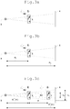
  • FIG. 2 is a schematic plan view of a focal point of the X-ray tube, the rotation center axis, the calibration instrument (instrument), and a detection surface of the X-ray detector that are provided for use in the calibration of the imaging magnification according to first embodiment.
  • the illustration of the table is omitted, and only the focal point of the X-ray tube and the detection surface of the X-ray detector are illustrated.
  • the instrument I before and after the tomographic imaging of the subject M (see Fig. 1 ), the instrument I is placed on the table 3 to make a relative position of the instrument I with respect to the rotation center axis Ax known without changing properties of the radiation source (see Fig. 1 ), and the imaging of the instrument I is performed by the X-ray detector 4 at the two points (the first point P 1 and the second point P 2 ) where the table 3 is positioned.
  • the linear drive mechanism 5 moves the table 3 on which the instrument I is placed (see Fig. 1 ), and the imaging is performed at the two points (the first point P 1 and the second point P 2 ) indicated by the solid line in Fig.
  • the order of the imaging at the first point P 1 and at the second point P 2 is not particularly limited.
  • the imaging of the instrument I may be performed at the second point P 2 after the imaging of the instrument I is performed at the first point P 1 that is the imaging position, or alternatively the imaging of the instrument I may be performed at the first point P 1 that is the imaging position after the imaging of the instrument I is performed at the second point P 2 .
  • the projection image of the instrument I is obtained.
  • examples of a condition where the properties of the radiation source are not changed include a condition where a tube voltage and a tube current of the X-ray tube 2 are constant. While the tube voltage and the tube current at the time of the tomographic imaging are constant through before and after the tomographic imaging of the subject M, the imaging of the instrument I is performed.
  • the condition where the properties of the radiation source are not changed is not limited to the condition where the tube voltage and the tube current are constant.
  • the condition for the properties of the radiation source may be set in accordance with a specification or type of the X-ray tube. For example, the condition for the properties of the radiation source may change depending on switch-on or switch-off of a main power supply of the X-ray tube.
  • the design dimension of the instrument I may be known.
  • the instrument I be made of an axially symmetric structure (sphere, cylinder, or cone) or a thin plate that allows feature point detection. Further, it is preferable that the instrument I be made from a material that highly contrasts with air in the projection image.
  • a distance SRD between the focal point of the X-ray tube 2 and the rotation center axis Ax of the table 3 at the first point P 1 calibrated at a past reference time is denoted by d 1
  • a distance SDD between the focal point of the X-ray tube 2 and the X-ray detector 4 calibrated at the reference time is denoted by D 0 .
  • the reference time is not particularly limited as long as it is before target calibration, and may be, for example, a time of shipment of the X-ray computed tomography scanner 1 (see Fig. 1 ).
  • the properties of the radiation source change every time the tomographic imaging is performed, and thus it is preferable that the calibration according to the present invention (including the first embodiment and the like) be performed every time the tomographic imaging is performed, and the SRD calibrated immediately before the target calibration be d 1 and the SDD calibrated immediately before the target calibration be D 0 .
  • the d 1 and D 0 thus set are temporary values.
  • a distance between the rotation center axes Ax of the table 3 at the first point P 1 and the second point P 2 is denoted by s (see also Fig. 1 )
  • sizes of projection images of the instrument I on the table 3 at the first point P 1 and the second point P 2 are denoted by L 1 and L 2 , respectively.
  • the instrument I is made of an axially symmetric structure having two markers that highly contrast with air in the projection image and between which the emitting axis passes through, and projection dimensions (inter-pixel distances) between the two markers on the projection image are denoted by L 1 , L 2 .
  • the design dimension (the distance between the markers in Fig. 2 ) of the instrument I is denoted by 1. Since the design dimension of the instrument I may be unknown as described above, the design dimension 1 of the instrument I may be either known or unknown.
  • an SRD to be calibrated is represented by d 1 ⁇ (t)
  • an SDD to be calibrated is represented by D ⁇ (t).
  • t denotes a calibration time
  • unknown d 1 ⁇ (t) and D ⁇ (t) can be each regarded as a function of the time t.
  • a geometric operation using the distance s between the rotation center axes Ax of the table 3 at the first point P 1 and the second point P 2 , the sizes L 1 , L 2 of the projection images of the instrument I on the table 3 at the first point P 1 and the second point P 2 is represented by the following equations (1), (2).
  • the SRD (d 1 ⁇ (t)) to be calibrated can be obtained by the following equation (4) without using the design dimension 1 of the instrument I.
  • d 1 * t s ⁇ L 2 / L 1 ⁇ L 2
  • the sizes L 1 , L 2 of the projection images of the instrument I in the above equation (4) are actual measurement values, and the distance s between the rotation center axes Ax of the table 3 at the first point P 1 the second point P 2 is known. Therefore, the SRD (d 1 ⁇ (t)) to be calibrated can be obtained by the above equation (4).
  • a difference (D ⁇ (t) - d 1 ⁇ (t)) between the SDD (D ⁇ (t)) at the calibration time t and the distance SRD (d 1 ⁇ (t)) at the calibration time t can be regarded as a distance between the X-ray detector 4 and the rotation center axis Ax of the table 3 at the first point P 1 .
  • the difference (D ⁇ (t) - d 1 ⁇ (t)) can be regarded as being constant irrespective of variations in the focal point of the X-ray tube 2, and the difference (D ⁇ (t) - d 1 ⁇ (t)) can be regarded as being equal to the difference (D 0 - d 1 ) between the SDD (D 0 ) calibrated at a past reference time and the SRD (d 1 ) calibrated at the reference time.
  • a ratio SDD/SRD between the distance SRD (d 1 ⁇ (t)) and SDD (D ⁇ (t)) obtained as described above is defined as the imaging magnification (calibrated imaging magnification).
  • the distances SRD, SDD are obtained using the following parameters (a) to (c).
  • (a) is the size L 1 of the projection image of the target object (the instrument I in the first embodiment) on the table 3 at the first point P 1 (that is the imaging position) and the size L 2 of the projection image of the target object (the instrument I) on the table 3 at the second point P 2 (different from the first point P 1 ).
  • (b) is the distance s between the rotation center axes Ax of the table 3 at the first point P 1 and the second point P 2 .
  • the distance SRD can be obtained based on the parameters of (a), (b).
  • the distance SDD can be obtained without using a parameter corresponding to a known design dimension of an instrument as used in the conventional method.
  • (c) is the distance between the X-ray detector 4 and the rotation center axis Ax of the table 3 at the first point P 1 (that is the imaging position).
  • the distance SRD when the distance SRD is accurately obtained based on the parameters (a), (b), a focal position of the radiation source (the X-ray tube 2 in the first embodiment) is also accurately obtained, allowing the distance SDD to be accurately obtained only by adding up the distance SRD accurately obtained and the parameter of (c).
  • SDD thus obtained as the imaging magnification at the first point P 1 allows the imaging magnification to be accurately calibrated. That is, even when the target object is the instrument I having an unknown dimension as in the first embodiment, it is possible to accurately obtain the distances SRD, SDD and the imaging magnification using the instrument I. As a result, even when any instrument I is used, the imaging magnification can be accurately calibrated.
  • the parameter (distance) of (c) does not vary with time and can be regarded as being constant.
  • the difference (D ⁇ (t) - d 1 ⁇ (t)) between the distance SDD (D ⁇ (t)) at the calibration time t and the distance SRD (d 1 ⁇ (t)) at the calibration time t can be regarded as the distance of (c) (that is, the distance between the X-ray detector 4 and the rotation center axis Ax of the table 3 at the first point P 1 ).
  • the distances SRD, SDD can be each obtained by solving the equation (the above equation (5)) in which the difference (D ⁇ (t) - d 1 ⁇ (t)) between the distance SDD (D ⁇ (t)) at the calibration time t and the distance SRD (d 1 ⁇ (t)) at the calibration time t is equal to the difference (D 0 - d 1 ) between the SDD (D 0 ) calibrated at a time before the calibration time t and the SRD (d 1 ) calibrated at the time.
  • the distances SRD, SDD and the imaging magnification can be accurately obtained by solving the equation (the above equation (5)) in which the parameter (distance) of (c) is unknown, but is constant without varying with time.
  • the projection image (the projection image of the instrument I in the first embodiment) used for obtaining the imaging magnification is an image obtained before and after the tomographic imaging of the subject M.
  • Obtaining the projection image or the CT image as in the second, fourth, and fifth embodiments (to be described later) before and after the tomographic imaging of the subject M corresponds to obtaining the projection image or the CT image in a state where the properties of the radiation source have not changed from when the tomographic imaging of the subject M is performed.
  • the projection image is a projection image of the instrument I captured by the X-ray detector 4 with the instrument I placed on the table 3 to make the relative position of the instrument I with respect to the rotation center axis Ax known.
  • the distance SRD is obtained by the geometric operation (the above equations (1), (2), or the above expression (4) that results from bringing together the equations (1), (2)) using the size L 1 of the projection image of the instrument I on the table 3 at the first point P 1 and the size L 2 of the projection image of the instrument I on the table 3 at the second point P 2 that correspond to the parameters of (a), and the distance s that corresponds to the parameter of (b).
  • the distance SDD is obtained by adding up the distance SRD thus obtained and the distance corresponding to the parameter of (c) (that is, the distance between the X-ray detector 4 and the rotation center axis Ax of the table 3 at the first point P 1 ).
  • the sizes L 1 , L 2 that correspond to the parameters of (a) of the projection images of the instrument I on the table 3 at the first point P 1 and the second point P 2 are actual measurement values captured by the X-ray detector 4, and the distance s that corresponds to the parameter of (b) between the rotation center axes Ax of the table 3 at the first point P 1 and the second point P 2 is known. Therefore, the distance SRD can be accurately obtained by the geometric operation (the above equations (1), (2), or the above equation (4) that results from bringing together the equations (1), (2)) using the parameters of (a) and (b). The distance SDD can also be accurately obtained only by adding up the distance SRD thus obtained and the parameter of (c).
  • Fig. 1 is a schematic side view of the X-ray computed tomography scanner according to each embodiment. Components identical to the components in the first embodiment described above are denoted by the same reference numerals, and descriptions and illustrations of the components are omitted. Note that, in the second embodiment in addition to the third to fifth embodiments (to be described later), the X-ray computed tomography scanner 1 shown in Fig. 1 that is the same as in the first embodiment is used.
  • the instrument I (see Fig. 2 ) is placed on the table 3 to make the relative position of the instrument I with respect to the rotation center axis Ax known, and the imaging of the instrument I is performed by the X-ray detector 4 at each of the two points (the first point P 1 and the second point P 2 ) where the table 3 is positioned to obtain the projection images of the instrument I.
  • the relative position with respect to the rotation center axis Ax is unknown. Therefore, the instrument I (see Fig. 3 ) is placed on the table 3 at the first point P 1 , and the tomographic imaging of the instrument I is performed by the X-ray detector 4 to obtain the CT image of the instrument I.
  • the CT image of the instrument I obtained through the tomographic imaging is sent to the imaging magnification calibrator 7 for use in the calibration of the imaging magnification. Furthermore, the projection images of the instrument I captured by the X-ray detector 4 at each of the two points (the first point P 1 and the second point P 2 ) where the table 3 is positioned are also sent to the imaging magnification calibrator 7 for use in the calibration of the imaging magnification.
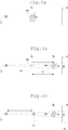
  • FIGs. 3a to 3c are schematic plan views of the focal point of the X-ray tube, the rotation center axis, the calibration instrument (instrument), and the detection surface of the X-ray detector that are provided for use in the calibration of the imaging magnification according to the second embodiment.
  • the illustration of the table is omitted, and only the focal point of the X-ray tube and the detection surface of the X-ray detector are illustrated in Figs. 3a to 3c .
  • the instrument I before and after the tomographic imaging of the subject M (see Fig. 1 ) or concurrently with the tomographic imaging of the subject M, the instrument I is placed on the table 3 (see Fig. 1 ) at the first point P 1 , and the tomographic imaging of the instrument I is performed by the X-ray detector 4 to obtain the CT image of the instrument I. Then, the relative position of the instrument I with respect to the rotation center axis Ax is obtained from pixel coordinates of the instrument I reflected in the CT image.
  • the instrument I is placed on the table 3 without changing the properties of the radiation source, and the imaging of the instrument I is performed by the X-ray detector 4 at each of the two points (the first point P 1 and the second point P 2 ) where the table 3 is positioned.
  • the linear drive mechanism 5 moves the table 3 on which the instrument I is placed (see Fig. 1 ), and the imaging is performed at the two points (the first point P 1 and the second point P 2 ) indicated by the solid line in Fig. 1 and the long dashed double-short dashed line in Fig. 1 .
  • the order of the imaging at the first point P 1 and the second point P 2 is not particularly limited.
  • the imaging of the instrument I may be performed at the second point P 2 after the imaging of the instrument I is performed at the first point P 1 that is the imaging position, or alternatively the imaging of the instrument I may be performed at the first point P 1 that is the imaging position after the imaging of the instrument I is performed at the second point P 2 .
  • the projection image of the instrument I is obtained.
  • examples of the condition where the properties of the radiation source are not changed include the condition where the tube voltage and the tube current of the X-ray tube 2 are constant as in the first embodiment. Therefore, while the tube voltage and the tube current at the time of the tomographic imaging are constant through before and after the tomographic imaging of the subject M or the tomographic imaging of the instrument I, the imaging of the instrument I is performed.
  • the condition where the properties of the radiation source are not changed is not limited to the condition where the tube voltage and tube current are constant.
  • the condition for the properties of the radiation source may be set in accordance with the specification or type of the X-ray tube. Conditions where the properties of the radiation source are not changed other than the condition where the tube voltage and the tube current are constant have already been described in the first embodiment; therefore, no description of such conditions is given here.
  • the instrument I whose design dimension is unknown is used, but as described in the first embodiment, the design dimension of the instrument I may be known.
  • a relative position vector of the instrument I with respect to the rotation center axis Ax in the actual CT image is denoted by l 1 (represented as a vector together with an arrow over l 1 in Fig. 3 or the following expressions).
  • l 1 represented as a vector together with an arrow over l 1 in Fig. 3 or the following expressions.
  • coordinates (x 1 , y 1 ) of a marker with the coordinates of the rotation center axis Ax taken as an origin
  • the relative position vector l 1 of the instrument I with respect to the rotation center axis Ax in the actual CT image is represented by (x 1 , y 1 ).
  • a distance SRD between the focal point of the X-ray tube 2 and the rotation center axis Ax of the table 3 (see Fig. 1 ) at the first point P 1 calibrated at a past reference time is denoted by d 1
  • a distance SDD between the focal point of the X-ray tube 2 and the X-ray detector 4 calibrated at the reference time is denoted by D 0 .
  • the properties of the radiation source changes every time the tomographic imaging is performed, and thus it is preferable that the calibration according to the present invention (including the second embodiment and the like) be performed every time the tomographic imaging is performed, and the SRD calibrated immediately before the target calibration be d 1 and the SDD calibrated immediately before the target calibration be D 0 .
  • the d 1 and D 0 thus set are temporary values.
  • the SRD, SDD to be calibrated can be accurately obtained by a geometric operation (to be described later).
  • the relative position vector l 2 (x 2 , y 2 ) is obtained through actual measurement of the coordinates (x 2 , y 2 ) of the instrument I reflected in the CT image captured through the tomographic imaging.
  • the relative position vector l 2 is obtained from the pixel coordinates of the instrument I reflected in the CT image captured through the tomographic imaging performed by the X-ray detector 4 with the instrument I placed on the table 3 at the first point P 1 .
  • the SRD to be calibrated is denoted by d 1 ⁇ (t)
  • the SDD to be calibrated is denoted by D ⁇ (t).
  • t denotes the calibration time
  • unknown d 1 ⁇ (t) and D ⁇ (t) can be each regarded as a function of time t.
  • a geometric operation using the distance s between the rotation center axes Ax of the table 3 at the first point P 1 and the second point P 2 , the sizes L 1 , L 2 of the projection images of the instrument I on the table 3 at the first point P 1 and the second point P 2 , and the coordinates (x 2 , y 2 ) that results from converting the relative position vector l 2 is represented by the following equations (6), (7).
  • D * t / d 1 * t + x 2 ⁇ y 2 L 1 / 2
  • D * t / d 1 * t + s + x 2 ⁇ y 2 L 2 / 2
  • the SRD (d 1 ⁇ t)) to be calibrated can be obtained using the coordinate x 2 of the relative position in the emitting axis direction, without using the coordinate y 2 of the relative position in a direction orthogonal to the emitting axis.
  • the design dimension 1 of the instrument I is the length in the direction orthogonal to the emitting axis
  • the design dimension 1 of the instrument I is replaced with the coordinate y 2 of the relative position in the direction orthogonal to the emitting axis.
  • the coordinate x 2 of the relative position in the emitting axis direction is included in the above equation (8). Therefore, in the second embodiment, the SRD (d 1 ⁇ (t)) to be calibrated can be obtained by including a parameter of the coordinate x 2 of the relative position in the geometric operation of the above equation (8).
  • the SDD (D ⁇ (t)) to be calibrated is obtained by solving the above equation (5) in the first embodiment (by adding up the SRD (d 1 ⁇ (t)) already obtained and the parameter (D 0 - d 1 )). Furthermore, the ratio SDD/SRD between the distances SRD, SDD is taken as the imaging magnification at the first point P 1 .
  • the relative position vector l 2 is multiplied by D 0 /d 1 ⁇ d 1 ⁇ (t)/D ⁇ (t) on the right side of the above expression (10) to eliminate the influence of enlargement or reduction and calibrated into the relative position vector l 1 .
  • the distance SRD can be obtained based on (a) the size L 1 of the projection image of the target object (the instrument I in the second embodiment) on the table 3 at the first point P 1 (that is the imaging position) and the size L 2 of the projection image of the target object (the instrument I) on the table 3 at the second point P 2 (that is different from the first point P 1 ), and (b) the distance s between the rotation center axes Ax of the table 3 at the first point P 1 and the second point P 2 .
  • the distance SDD can be obtained by adding up the distance SRD thus obtained and (c) the distance between the X-ray detector 4 and the rotation center axis Ax of the table 3 at the first point P 1 (that is the imaging position), and the imaging magnification can be calibrated by taking the ratio between the distances SRD, SDD thus obtained as the imaging magnification at the first point P 1 .
  • the imaging magnification can be accurately calibrated.
  • the projection image (the projection image of the instrument I in the second embodiment) and the CT image (the CT image of the instrument I in the second embodiment) used for obtaining the imaging magnification are images obtained before and after the tomographic imaging of the subject M.
  • the CT image of the instrument I obtained concurrently with the tomographic imaging of the subject M may be used for obtaining the imaging magnification.
  • obtaining the projection image or the CT image before and after the tomographic imaging of the subject M corresponds to obtaining the projection image or the CT image in a state where the properties of the radiation source have not changed from when the tomographic imaging of the subject M is performed.
  • the CT image of the instrument I When the CT image of the instrument I is obtained concurrently with the tomographic imaging of the subject M, the CT image of the subject M through the tomographic imaging of the subject M and the CT image of the instrument I used for obtaining the imaging magnification can be obtained concurrently in a state where the properties of the radiation source have not surely changed.
  • the table 3 In order to obtain the CT image of the instrument I concurrently with the tomographic imaging of the subject M, the table 3 is positioned at the first point P 1 that is the imaging position, and the tomographic imaging is performed with the subject M and the instrument I concurrently placed on the same table 3.
  • the relative position of the instrument I with respect to the rotation center axis Ax is obtained from the pixel coordinates of the instrument I reflected in the CT image captured through the tomographic imaging performed by the X-ray detector 4 with the instrument I placed on the table 3 at the first point P 1 .
  • the projection image is a projection image of the instrument I captured by the X-ray detector 4, and the distance SRD is obtained by the geometric operation (the above equations (6), (7), or the above equation (8) that results from bringing together the equations (6), (7)) using the size L 1 of the projection image of the instrument I on the table 3 at the first point P 1 and the size L 2 of the projection image of the instrument I on the table 3 at the second point P 2 that correspond to the parameters of (a), the distance s corresponding to the parameter of (b), and (d) the relative position of the instrument I with respect to the rotation center axis Ax.
  • the distance SDD is obtained by adding up the distance SRD thus obtained and the distance corresponding to the parameter of (c) (that is, the distance between the X-ray detector 4 and the rotation center axis Ax of the table 3 at the first point P 1 ).
  • the relative position of the instrument I with respect to the rotation center axis Ax is known, but in the second embodiment, the relative position of the instrument I with respect to the rotation center axis Ax is unknown. Therefore, the CT image of the instrument I is obtained through the tomographic imaging performed by the X-ray detector 4 with the instrument I placed on the table 3 at the first point P 1 . The relative position of the instrument I with respect to the rotation center axis Ax is obtained from the pixel coordinates of the instrument I reflected in the CT image.
  • the distance SRD can be accurately obtained by the geometric operation (the above equations (6), (7), or the above equation (8) that results from bringing together the equations (6), (7)) using the parameter of (d) in the second embodiment in addition to the parameters of (a) and (b) in first embodiment.
  • the distance SDD can also be accurately obtained only by adding up the distance SRD thus obtained and the parameter of (c).
  • Fig. 1 is a schematic side view of the X-ray computed tomography scanner according to each embodiment.
  • Components identical to the components in the first and second embodiments are denoted by the same reference numerals, and descriptions and illustrations of the components are omitted. Note that, in the third embodiment in addition to the fourth and fifth embodiments (to be described later), the X-ray computed tomography scanner 1 shown in Fig. 1 that is the same as in the first and second embodiments is used.
  • an image (the projection image of the instrument I or the CT image of the instrument I) obtained through the imaging or the tomographic imaging performed on the instrument I serving as the target object (see Fig. 2 or 3 ) is provided for use in the calibration of the imaging magnification.
  • an image (the projection image of the subject M or the CT image of the subject M) obtained through the imaging or the tomographic imaging performed on the subject M serving as the target object that is subject to the tomographic imaging is provided for use in the calibration of the imaging magnification.
  • the CT image of the subject M is obtained through the tomographic imaging performed by the X-ray detector 4 with the subject M placed on the table 3 at the first point P 1 .
  • the CT image of the subject M obtained through the tomographic imaging is sent to the imaging magnification calibrator 7 for use in the calibration of the imaging magnification. Furthermore, an actually measured projection image and a simulation projection image (to be described later) are also sent to the imaging magnification calibrator 7 for use in the calibration of the imaging magnification.
  • Figs. 4a to 4c are schematic plan views of the focal point of the X-ray tube, the rotation center axis, the subject, and the detection surface of the X-ray detector that are provided for use in the calibration of the imaging magnification according to the third embodiment.
  • the illustration of the table is omitted, and only the focal point of the X-ray tube and the detection surface of the X-ray detector are illustrated in Fig. 4 .
  • a structure of the subject indicating the size of the CT image of the subject M at the first point P 1 is obtained.
  • the table 3 is positioned at the second point P 2 that is distanced from the first point P 1 by the distance s (see Fig. 4b ) without changing the properties of the radiation source, the actually measured projection image that is projected from the structure of the subject M and captured by the X-ray detector 4 is obtained.
  • the linear drive mechanism 5 moves the table 3 on which the subject M is placed (see Fig. 1 ), and the imaging is performed at the two points (the second point P 2 ) indicated by the long dashed double-short dashed line in Fig. 1 .
  • the actually measured projection image of the subject M is obtained through the imaging of the structure of the subject M in which the structure of the subject M is projected and captured by the X-ray detector 4. As shown in Fig. 4b , the actually measured projection image is denoted by A.
  • the simulation projection image that is projected from the structure of the subject M while moving the focal point of the X-ray tube 2 in a pseudo manner is obtained.
  • the simulation projection image is denoted by B.
  • the simulation projection image corresponds to a projection image that is formed by lines connecting the focal point of the X-ray tube 2 and the structure (contour) of the subject M without actually emitting the X-rays from the X-ray tube 2 and projected along extension lines of the formation lines and onto the detection surface of the X-ray detector.
  • the distance SRD can be obtained based on (a) the size of the CT image (the structure of the subject M indicating the size of the CT image of the subject M in the third embodiment) of the target object (the subject M in the third embodiment) on the table 3 at the first point P 1 (that is the imaging position) and the size of the projection image (the actually measured projection image A and the simulation projection image B projected from the structure of the subject M in the third embodiment) on the table 3 at the second point P 2 (that is different from the first point P 1 ), and (b) the distance s between the rotation center axes Ax of the table 3 at the first point P 1 and the second point P 2 .
  • the distance SDD can be obtained by adding up the distance SRD thus obtained and (c) the distance between the X-ray detector 4 and the rotation center axis Ax of the table 3 at the first point P 1 (that is the imaging position), and the imaging magnification can be calibrated by taking the ratio between the distances SRD, SDD thus obtained as the imaging magnification at the first point P 1 .
  • the imaging magnification can be accurately calibrated.
  • the image (the projection image of the subject M or the CT image of the subject M) obtained through the imaging or the tomographic imaging performed on the subject M serving as the target object that is subject to the tomographic imaging is provided for use in the calibration of the imaging magnification. Therefore, from the CT image captured through the tomographic imaging performed by the X-ray detector 4 with the subject M placed on the table 3 at the first point P 1 , the structure of the subject M indicating the size corresponding to the parameter of (a) of the CT image of the subject M at the first point P 1 is obtained.
  • the table 3 When the table 3 is positioned at the second point P 2 that is distanced from the first point P 1 by the distance s corresponding to the parameter of (b), the actually measured projection image that is projected from the structure of the subject M and captured by the X-ray detector 4 is obtained.
  • the structure of the subject M indicating the size of the CT image of the subject M is also enlarged or reduced relative to the actual CT image of the subject M. Furthermore, since the subject M that is subject to the tomographic imaging is any subject M whose dimensions are unknown, it is not easy to obtain actual dimensions of the subject M only from the actually measured projection image A that is projected from the structure of the subject M and captured by the X-ray detector 4.
  • the simulation projection image B that is projected from the structure of the subject M while moving the focal point of the radiation source (the X-ray tube 2 in the third embodiment) in a pseudo manner is used.
  • the actually measured projection image A and the simulation projection image B identical in size to each other, matching between the size of the actually measured projection image A and the size of the simulation projection image B is performed while moving the focal point of the radiation source (the X-ray tube 2) in a pseudo manner.
  • the distance between the focal point of the radiation source (the X-ray tube 2) and the rotation center axis Ax of the table 3 at the first point P 1 when the matching between the simulation projection image B and the actually measured projection image A is accomplished can be accurately obtained as the distance SRD.
  • the distance between the focal point of the radiation source (the X-ray tube 2) and the X-ray detector 4 when the matching between the simulation projection image B and the actually measured projection image A is accomplished can be accurately obtained as the distance SDD only by adding up the distance SRD thus obtained and the distance corresponding to the parameter of (c) (that is, the distance between the X-ray detector 4 and the rotation center axis Ax of the table 3 at the first point P 1 ).
  • Fig. 1 is a schematic side view of the X-ray computed tomography scanner according to each embodiment.
  • Components identical to the components in the first to third embodiments are denoted by the same reference numerals, and descriptions and illustrations of the components are omitted.
  • the X-ray computed tomography scanner 1 shown in Fig. 1 that is the same as in the first to third embodiments is used.
  • the projection image is provided for use in the calibration of the imaging magnification.
  • only the CT image of the instrument I is provided for use in the calibration of the imaging magnification.
  • the CT image of the instrument I at the first point P 1 is obtained through the tomographic imaging performed by the X-ray detector 4 with the instrument I placed on the table 3 at the first point P 1
  • the CT image of the instrument I at the second point P 2 is obtained through the tomographic imaging performed by the X-ray detector 4 with the instrument I placed on the table 3 at the second point P 2 .
  • the CT image of the instrument I obtained through the tomographic imaging is sent to the imaging magnification calibrator 7 for use in the calibration of the imaging magnification.
  • FIGs. 5a and 5b are schematic plan views of the focal point of the X-ray tube, the rotation center axis, the calibration instrument (instrument), and the detection surface of the X-ray detector that are provided for use in the calibration of the imaging magnification according to the fourth embodiment.
  • the illustration of the table is omitted, and only the focal point of the X-ray tube and the detection surface of the X-ray detector are illustrated in Fig. 5 .
  • the instrument I before and after the tomographic imaging of the subject M (see Fig. 1 ), the instrument I is placed on the table 3 (see Fig. 1 ) without changing properties of the radiation source, and the tomographic imaging is performed by the X-ray detector 4 on the instrument I at each of the two points (the first point P 1 and the second point P 2 ) where the table 3 is positioned.
  • the linear drive mechanism 5 moves the table 3 on which the instrument I is placed, and the tomographic imaging is performed at the two points (the first point P 1 and the second point P 2 ) indicated by the solid line in Fig. 1 and the long dashed double-short dashed line in Fig. 1 .
  • the order of the imaging at the first point P 1 and the second point P 2 is not particularly limited.
  • the tomographic imaging of the instrument I may be performed at the second point P 2 after the tomographic imaging of the instrument I is performed at the first point P 1 that is the imaging position, or alternatively the tomographic imaging of the instrument I may be performed at the first point P 1 that is the imaging position after the tomographic imaging of the instrument I is performed at the second point P 2 .
  • the CT image of the instrument I is obtained.
  • examples of the condition where the properties of the radiation source are not changed include the condition where the tube voltage and the tube current of the X-ray tube 2 are constant as in the first and second embodiments. Therefore, while the tube voltage and the tube current at the time of the tomographic imaging are constant through before and after the tomographic imaging of the subject M, the tomographic imaging of the instrument I is performed.
  • the condition where the properties of the radiation source are not changed is not limited to the condition where the tube voltage and tube current are constant.
  • the condition for the properties of the radiation source may be set in accordance with the specification or type of the X-ray tube. Conditions where the properties of the radiation source are not changed other than the condition where the tube voltage and the tube current are constant have already been described in the first embodiment; therefore, no description of such conditions is given here.
  • the instrument I whose design dimension is unknown is used, but as described in the first embodiment, the design dimension of the instrument I may be known.
  • the SRD to be calibrated is denoted by d 1 ⁇ (t)
  • the SDD to be calibrated is denoted by D ⁇ (t).
  • t denotes the calibration time
  • unknown d 1 ⁇ (t) and D ⁇ (t) can be each regarded as a function of time t.
  • the design dimension (the distance between the markers in Fig. 5 ) of the instrument I is denoted by 1, as in the first embodiment.
  • a geometric operation using the distance s between the rotation center axes Ax of the table 3 at the first point P 1 and the second point P 2 , the sizes l 1 , l 2 of the CT images of the instrument I on the table 3 at the first point P 1 and the second point P 2 is represented by the following equations (11) and (12).
  • the SRD (d 1 ⁇ (t)) to be calibrated can be obtained by the following equation (14) without using the design dimension 1 of the instrument I.
  • d 1 * t s ⁇ d 1 ⁇ l 2 / d 1 ⁇ l 1 + s ⁇ l 1 ⁇ d 1 ⁇ l 2
  • the sizes l 1 , l 2 of the CT images of the instrument I in the above equation (14) are actual measurement values, the distance s between the rotation center axes Ax of the table 3 at the first point P 1 and the second point P 2 is known, and the temporarily set SRD (d 1 ) is an SRD calibrated immediately before the target calibration and is known. Therefore, the SRD (d 1 ⁇ (t)) to be calibrated can be obtained by the above equation (14).
  • the SDD (D ⁇ (t)) to be calibrated is obtained by solving the above equation (5) in the first embodiment (by adding up the SRD (d 1 ⁇ (t)) already obtained and the parameter (D 0 - d 1 )). Furthermore, the ratio SDD/SRD between the distances SRD, SDD is taken as the imaging magnification at the first point P 1 .
  • the distance SRD can be obtained based on (a) the size l 1 of the CT image of the target object (the instrument I in the fourth embodiment) on the table 3 at the first point P 1 (that is the imaging position) and the size l 2 of the CT image of the target object (the instrument I) on the table 3 at the second point P 2 (that is different from the first point P 1 ), and (b) the distance s between the rotation center axes Ax of the table 3 at the first point P 1 and the second point P 2 .
  • the distance SDD can be obtained by adding up the distance SRD thus obtained and (c) the distance between the X-ray detector 4 and the rotation center axis Ax of the table 3 at the first point P 1 (that is the imaging position), and the imaging magnification can be calibrated by taking the ratio between the distances SRD, SDD thus obtained as the imaging magnification at the first point P 1 .
  • the imaging magnification can be accurately calibrated.
  • the CT image of the instrument I is provided for use in the calibration of the imaging magnification.
  • the CT image of the instrument I since the CT image of the instrument I does not use the SRD, SDD to be calibrated, the CT image of the instrument I is enlarged or reduced relative to the actual CT image of the instrument I.
  • the CT image when the CT image is obtained based on accurately calibrated SRD, SDD, the CT image having actual dimensions can be obtained regardless of the position (imaging position) of table 3.
  • SRD, SDD that have not been calibrated do not have correct values due to variations in the focal position of the radiation source (the X-ray tube 2 in the fourth embodiment). Therefore, when the SRD, SDD that have not been calibrated are used, the size of the CT image varies with the position (imaging position) of table 3.
  • the sizes l 1 , l 2 corresponding to the parameters of (a) of the CT images of the instrument I on the table 3 at the first point P 1 and the second point P 2 are actual measurement values based on the tomographic imaging performed by the X-ray detector 4, and the distance corresponding to the parameter of (b) between the rotation center axes Ax of the table 3 at the first point P 1 and the second point P 2 is known. Therefore, the distance SRD can be accurately obtained by the geometric operation (the above equations (11), (12), or the above equation (14) that results from bringing together the equations (11), (12)) using the parameters of (a) and (b). The distance SDD can also be accurately obtained only by adding up the distance SRD thus obtained and the parameter of (c).
  • Fig. 1 is a schematic side view of the X-ray computed tomography scanner according to each embodiment. Components identical to the components in the first to fourth embodiments are denoted by the same reference numerals, and descriptions and illustrations of the components are omitted. Note that, in the fifth embodiment, the X-ray computed tomography scanner 1 shown in Fig. 1 that is the same as in the first to fourth embodiments is used.
  • an image (the projection image of the instrument I or the CT image of the instrument I) obtained through the imaging or the tomographic imaging performed on the instrument I serving as the target object (see Fig. 2 or 3 ) is provided for use in the calibration of the imaging magnification.
  • an image (the CT image of the subject M) obtained through the tomographic imaging performed on the subject M serving as the target object that is subject to the tomographic imaging is provided for use in the calibration of the imaging magnification as in the third embodiment.
  • the CT image of the subject M at the first point P 1 is obtained through the tomographic imaging performed by the X-ray detector 4 with the subject M placed on the table 3 at the first point P 1
  • the CT image of the subject M at the second point P 2 is obtained through the tomographic imaging performed by the X-ray detector 4 with the subject M placed on the table 3 at the second point P 2
  • the CT image of the subject M obtained through the tomographic imaging is sent to the imaging magnification calibrator 7 for use in the calibration of the imaging magnification.
  • FIGs. 6a and 6b are schematic plan views of the focal point of the X-ray tube, the rotation center axis, the subject, and the detection surface of the X-ray detector that are provided for use in the calibration of the imaging magnification according to the fifth embodiment.
  • the illustration of the table is omitted, and only the focal point of the X-ray tube and the detection surface of the X-ray detector are illustrated in Fig. 6 .
  • the instrument I in addition to the tomographic imaging of the subject M, the instrument I is placed on the table 3 (see Fig. 1 ) at the second point P 2 different from the first point P 1 that is the imaging position without changing the properties of the radiation source, and the tomographic imaging of the subject M is performed by the X-ray detector 4 at the second point P 2 .
  • the linear drive mechanism 5 moves the table 3 on which the subject M is placed (see Fig. 1 ), and the tomographic imaging is performed at the two points (the second point P 2 ) indicated by the long dashed double-short dashed line in Fig. 1 .
  • the order of the imaging at the first point P 1 and the second point P 2 is not particularly limited.
  • the tomographic imaging of the subject M may be performed at the second point P 2 after the tomographic imaging of the subject M is performed at the first point P 1 that is the imaging position, or alternatively the tomographic imaging of the subject M may be performed at the first point P 1 that is the imaging position after the tomographic imaging of the subject M is performed at the second point P 2 .
  • the CT image of the subject M is obtained.
  • the CT image of the subject M taken at the first point P 1 is denoted by C
  • the CT image of the subject M taken at the second point P 2 is denoted by D.
  • examples of the condition where the properties of the radiation source are not changed include the condition where the tube voltage and the tube current of the X-ray tube 2 are constant as in the first, second, and fourth embodiments. Therefore, while the tube voltage and the tube current at the time of the tomographic imaging are constant through before and after the tomographic imaging of the subject M, the tomographic imaging of the instrument I is performed.
  • the condition where the properties of the radiation source are not changed is not limited to the condition where the tube voltage and tube current are constant.
  • the condition for the properties of the radiation source may be set in accordance with the specification or type of the X-ray tube. Conditions where the properties of the radiation source are not changed other than the condition where the tube voltage and the tube current are constant have already been described in the first embodiment; therefore, no description of such conditions is given here.
  • a simulation CT image is obtained while moving the focal point of the X-ray tube 2 in a pseudo manner with the position of the table 3 fixed at the first point P 1 and the second point P 2 where the tomographic imaging is performed.
  • the simulation CT image is denoted by E.
  • the simulation CT image corresponds to an image that results from enlarging or reducing a CT image C and a CT image D in accordance with the magnification varying due to the pseudo movement of the focal point of the X-ray tube 2.
  • a distance between the focal point of the X-ray tube 2 and the X-ray detector 4 when the matching between the simulation CT images E at the first point P 1 and the second point P 2 is accomplished is obtained as the distance SDD. Furthermore, the ratio SDD/SRD between the distances SRD, SDD is taken as the imaging magnification at the first point P 1 .
  • the distance SRD can be obtained based on (a) the size of the CT image of the target object (the subject M in the fifth embodiment) on the table 3 at the first point P 1 (that is the imaging position) and the size of the CT image of the target object (the subject M) on the table 3 at the second point P 2 (that is different from the first point P 1 ), and (b) the distance s between the rotation center axes Ax of the table 3 at the first point P 1 and the second point P 2 .
  • the distance SDD can be obtained by adding up the distance SRD thus obtained and (c) the distance between the X-ray detector 4 and the rotation center axis Ax of the table 3 at the first point P 1 (that is the imaging position), and the imaging magnification can be calibrated by taking the ratio between the distances SRD, SDD thus obtained as the imaging magnification at the first point P 1 .
  • the imaging magnification can be accurately calibrated.
  • an image (the CT image of the subject M) obtained through the tomographic imaging performed on the subject M serving as the target object that is subject to the tomographic imaging is provided for use in the calibration of the imaging magnification as in the third embodiment. Therefore, the CT image of the subject M is obtained through the tomographic imaging performed by the X-ray detector 4 with the subject M placed on the table 3 at the first point P 1 . Further, the CT image of the subject M is obtained through the tomographic imaging performed by the X-ray detector 4 with the subject M placed on the table 3 at the second point P 2 .
  • the CT image of the subject M does not use the SRD, SDD to be calibrated, the CT image of the subject M is enlarged or reduced relative to the actual CT image of the subject M, as in the third embodiment.
  • the CT image having actual dimensions can be obtained regardless of the position (imaging position) of table 3.
  • SRD, SDD that have not been calibrated do not have correct values due to variations in the focal position of the radiation source (the X-ray tube 2 in the fifth embodiment). Therefore, when the SRD, SDD that have not been calibrated are used, the size of the CT image varies with the position (imaging position) of table 3.
  • the subject M that is subject to the tomographic imaging is any subject M whose dimensions are unknown, it is not easy to obtain actual dimensions of the subject M only from the CT image of the subject M captured through the tomographic imaging performed by the X-ray detector 4. Therefore, the CT image C captured through the tomographic imaging performed by the X-ray detector 4 with the subject M placed on the table 3 at the first point P 1 , and the CT image D captured through the tomographic imaging performed by the X-ray detector 4 with the subject M placed on the table 3 at the second point P 2 that is distanced from the first point P 1 by the distance s corresponding to the parameter of (b) are each obtained, and the following matching is performed to make the CT images identical in size to each other.
  • the matching between the simulation CT images E at the first point P 1 and the second point P 2 is performed while moving the focal point of the radiation source (the X-ray tube 2 in the fifth embodiment) in a pseudo manner with the position of the table 3 fixed at the first point P 1 and the second point P 2 where the tomographic imaging is performed.
  • the distance between the focal point of the radiation source (the X-ray tube 2) and the rotation center axis Ax of the table 3 at the first point P 1 when the matching between the simulation CT images E at the first point P 1 and the second point P 2 is accomplished can be accurately obtained as the distance SRD.
  • the distance between the focal point of the radiation source (the X-ray tube 2) and the X-ray detector 4 when the matching between the simulation CT images E at the first point P 1 and the second point P 2 can be accurately obtained as the distance SDD only by adding up the distance SRD thus obtained and the distance corresponding to the parameter of (c) (that is, the distance between the X-ray detector 4 and the rotation center axis Ax of the table 3 at the first point P 1 ).
  • the present invention is not limited to the above embodiments, and may be modified as follows.

Landscapes

  • General Physics & Mathematics (AREA)
  • Physics & Mathematics (AREA)
  • Health & Medical Sciences (AREA)
  • Life Sciences & Earth Sciences (AREA)
  • General Health & Medical Sciences (AREA)
  • Pathology (AREA)
  • Chemical & Material Sciences (AREA)
  • Immunology (AREA)
  • Biochemistry (AREA)
  • Analytical Chemistry (AREA)
  • Theoretical Computer Science (AREA)
  • Engineering & Computer Science (AREA)
  • Toxicology (AREA)
  • High Energy & Nuclear Physics (AREA)
  • Spectroscopy & Molecular Physics (AREA)
  • Molecular Biology (AREA)
  • Nuclear Medicine, Radiotherapy & Molecular Imaging (AREA)
  • Pulmonology (AREA)
  • Radiology & Medical Imaging (AREA)
  • Analysing Materials By The Use Of Radiation (AREA)
  • Apparatus For Radiation Diagnosis (AREA)

Abstract

A distance SRD can be obtained from sizes (L), (L) of projection images of a calibration instrument (instrument) (I) on a table at a first point (P) (that is an imaging position) and a second point (P) (different from the first point (P)) and a distance (s) between rotation center axes (Ax) of the table at the first point (P) and the second point (P). Furthermore, a distance SDD can be obtained by adding up the distance SRD thus obtained and a distance between an X-ray detector (4) and the rotation center axis (Ax) of the table at the first point (P), and a ratio between the distances SRD, SDD is taken as an imaging magnification of imaging at the first point (P).
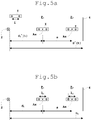
Description

    Technical Field
  • The present invention relates to a method for calibrating an imaging magnification of a radiation computed tomography scanner.
  • Background Art
  • A radiation computed tomography (CT) scanner (CT scanner) used as an industrial CT scanner such as a nondestructive inspection apparatus mainly includes the following three components. That is, such a CT scanner includes a radiation source configured to emit radiation, a table on which a subject is placed, the table being rotatable about a rotation center axis, and a radiation detector facing the radiation source with the table interposed between the radiation detector and the radiation source.
  • Any subject is placed on the table, and the table is rotated about the rotation center axis while causing the radiation source to emit radiation, thereby performing tomographic imaging. The radiation transmitted through the subject is detected by the radiation detector, and then reconstruction processing is performed on a plurality of projection images captured by the radiation detector to obtain a tomographic image of the subject. Here, on the basis of the distance from the radiation source to the rotation center axis of the table (SRD: Source-to-Rotation center Distance) and the distance from the radiation source to the radiation detector (SDD: Source-to-Detector Distance), an imaging magnification of the projection images can be defined as SDD/SRD. Therefore, accurately obtaining the imaging magnification allows dimensions of the tomographic image of the subject to be accurately grasped.
  • In practice, a focal position of the radiation source varies due to thermal expansion of a target that generates radiation, and properties of the radiation source such as a focal diameter also vary with a radiation condition. This causes the SDD and the SRD to vary. Therefore, unless the SDD and the SRD are accurately obtained, it is impossible to accurately grasp the dimensions of the tomographic image of the subject. In other words, when the SDD and the SRD are not accurate values, the dimensions of the obtained tomographic image of the subject deviate from a true value.
  • To cope with this, there are techniques of correctly obtaining the SDD and the SRD to calibrate the imaging magnification (e.g., refer to Patent Literature 1 and Patent Literature 2). As shown in Fig. 7, a linear drive mechanism MC that linearly moves a table T along an axis (also referred to as an "emitting axis") connecting a radiation source S and a center of a radiation detector D is provided, and an appropriate calibration instrument (also referred to as a "dedicated instrument" or simply referred to as an "instrument") whose relative position with respect to a rotation center axis is known is placed on the table T. In a technique disclosed in Patent Literature 1: JP 4396796 B2 , after an image of the instrument is captured at a certain point, the instrument is linearly moved to a different point by the linear drive mechanism MC together with the table T along the emitting axis, and then another image of the instrument is captured. As described above, the image of the instrument is captured at the two points, allowing the SDD and the SRD at a specific position to be calibrated by a geometric operation. Note that in such a conventional calibration method, an instrument whose design dimension is known is used.
  • Further, in a technique disclosed in Patent Literature 2: JP 2013-217773 A , a shielding member having a surface inclined toward a specific focal position is disposed close to the radiation detector. When the specific focal position varies in an emitting axis direction in Fig. 11 of Patent Literature 2 (a Z direction in Fig. 11) or in a horizontal direction in Fig. 13 of Patent Literature 2 (a Y direction in Fig. 13) orthogonal to the emitting axis, a thickness of a shadow formed by the shielding member varies as shown in Figs. 12 and 14 of Patent Literature 2. It is possible to obtain, from this shadow, a varying focal position or a reduction rate of a projection image.
  • Citation List Patent Literature
    • Patent Literature 1: JP 4396796 B2 (Fig. 1)
    • Patent Literature 2: JP 2013-217773 A (pages 21 and 22, Figs. 11 to 14)
    Summary of Invention Technical Problem
  • However, since such a conventional method is based on the premise that the design dimension of the above-described instrument used in calibration is known, there is a problem that high shape accuracy of the calibration instrument is required to accurately obtain the imaging magnification.
  • That is, in the calibration as disclosed in Patent Literature 1: JP 4396796 B2 , a projection dimension (inter-pixel distance) of the instrument on the projection image is actually measured. In order to accomplish highly accurate detection with the radiation detector for obtaining the projection image, it is preferable that the instrument be as close as possible to the radiation source. This makes it necessary to miniaturize the instrument, and thus makes it difficult to require high shape accuracy of the instrument. As described above, it is desired to accurately obtain the SDD and the SRD even for an instrument that does not require high shape accuracy, an instrument whose design dimension is unknown, or a subject that is subject to tomographic imaging.
  • The present invention has been made in view of the above circumstances, and an object of the present invention is to provide a method for calibrating an imaging magnification of a radiation computed tomography scanner capable of accurately calibrating an imaging magnification even with any calibration instrument or subject that is subject to tomographic imaging.
  • Solution to Problem
  • In order to achieve the object, the present invention is configured as follows.
  • That is, a method for calibrating an imaging magnification of a radiation computed tomography scanner according to the present invention, the radiation computed tomography scanner including a radiation source configured to emit radiation, a table on which a target object is placed, the table being rotatable about a rotation center axis and linearly movable in an emitting axis direction of the radiation between a first point that is an imaging position and a second point that is different from the first point, and a radiation detector facing the radiation source with the table interposed between the radiation detector and the radiation source, the radiation computed tomography scanner being configured to rotate the table about the rotation center axis to obtain a plurality of projection images and create a CT image, includes obtaining a distance SRD between a focal point of the radiation source and the rotation center axis of the table at the first point based on (a) a size of a projection image or a CT image of the target object on the table at the first point and a size of a projection image or a CT image of the target object on the table at the second point and (b) a distance between the rotation center axis of the table at the first point and the rotation center axis of the table at the second point, obtaining a distance SDD between the focal point of the radiation source and the radiation detector by adding up the distance SRD thus obtained and (c) a distance between the radiation detector and the rotation center axis of the table at the first point, and setting a ratio between the distances SRD, SDD thus obtained as an imaging magnification of imaging at the first point.
  • [Operation and effect]
  • By the method for calibrating an imaging magnification of a radiation computed tomography scanner according to the present invention, in order to calibrate the imaging magnification of the radiation computed tomography scanner, the table rotates about the rotation center axis to obtain a plurality of projection images and create a CT image, the distances SRD, SDD are obtained using the following parameters of (a) to (c).
  • (a) is a size of a projection image or a CT image of the target object on the table at the first point (that is the imaging position) and a size of a projection image or a CT image of the target object on the table at the second point (different from the first point). (b) is a distance between the rotation center axis of the table at the first point and the rotation center axis of the table at the second point. The distance SRD can be obtained based on the parameters of (a), (b).
  • In the present invention, based on the premise that the following parameter of (c) is known or basically known, the distance SDD can be obtained without using a parameter corresponding to a known design dimension of a calibration instrument as used in the conventional method. (c) is a distance between the radiation detector and the rotation center axis of the table at the first point (that is the imaging position).
  • Therefore, when the distance SRD is accurately obtained based on the parameters of (a), (b), the focal position of the radiation source is also accurately obtained, allowing the distance SDD to be accurately obtained only by adding up the distance SRD accurately obtained and the parameter of (c). Taking the ratio between the distances SRD, SDD thus obtained as an imaging magnification at the first point allows the imaging magnification to be accurately calibrated. That is, even when the target object is a calibration instrument whose dimensions are unknown or a subject that is subject to tomographic imaging, it is possible to accurately calculate the distances SRD, SDD and the imaging magnification using such a calibration instrument or subject. As a result, even when any calibration instrument or a subject that is subject to tomographic imaging is used, the imaging magnification can be accurately calibrated.
  • In the present invention, even when the focal position of the radiation source varies with time, the parameter (distance) of (c) does not vary with time and can be regarded as being constant. A difference between a distance SDD at a calibration time t and a distance SRD at the calibration time t can be regarded as the distance of (c) (that is, the distance between the radiation detector and the rotation center axis of the table at the first point). Therefore, even at any calibration time t, the difference can be regarded as being constant irrespective of variations in the focal point of the radiation source, and the difference can be regarded as being equal to a difference between an SDD calibrated at a time before the calibration time t and an SRD calibrated at the time. As a result, the distances SRD, SDD can be each obtained by solving an equation in which the difference between the distance SDD at the calibration time t and the distance SRD at the calibration time t is equal to the difference between the SDD calibrated at the time before the calibration time t and the SRD calibrated at the time. As described above, the distances SRD, SDD and the imaging magnification can be accurately obtained by solving the equation in which the parameter (distance) of (c) is unknown, but is constant without varying with time.
  • The projection image or the CT image used for obtaining the imaging magnification may be an image obtained before and after tomographic imaging of the subject, and the CT image may be an image of the calibration instrument obtained concurrently with tomographic imaging of the subject. Obtaining the projection image or the CT image before and after tomographic imaging of the subject corresponds to obtaining the projection image or the CT image in a state where the properties of the radiation source have not changed from when the tomographic imaging of the subject is performed. When the CT image of the calibration instrument is obtained concurrently with tomographic imaging of the subject, the CT image of the subject through tomographic imaging of the subject and the CT image of the calibration instrument used for obtaining the imaging magnification can be obtained concurrently in the state where the properties of the radiation source have not surely changed. In order to obtain the CT image of the calibration instrument concurrently with tomographic imaging of the subject, the table is positioned at the first point that is the imaging position, and tomographic imaging is performed with the subject and the calibration instrument concurrently placed on the same table.
  • Examples of a specific aspect for obtaining each of the distances SRD, SDD include the following aspects (first to fifth aspects).
  • The projection image is a projection image of the calibration instrument captured by the radiation detector with the calibration instrument placed on the table to make a relative position with respect to the rotation center axis known, the distance SRD is obtained by a geometric operation using a size corresponding to the (a) of the projection image of the calibration instrument on the table at the first point and a size corresponding to the (a) of the projection image of the calibration instrument on the table at the second point and the distance of (b), and the distance SDD is obtained by adding up the distance SRD thus obtained and the distance of (c) (first aspect).
  • In the first aspect, the sizes corresponding to the parameters of (a) of the projection images of the calibration instrument on the table at the first point and the second point are actual measurement values captured by the radiation detector, and the distance corresponding to the parameter of (b) between the rotation center axis of the table at the first point and the rotation center axis of the table at the second point is known. Therefore, the distance SRD can be accurately obtained by the geometric operation using the parameters of (a) and (b). The distance SDD can also be accurately obtained only by adding up the distance SRD thus obtained and the parameter of (c).
  • Further, to obtain the distance SRD based on the image sizes of (a) and the distance of (b), a relative position of the calibration instrument with respect to the rotation center axis is obtained from pixel coordinates of the calibration instrument reflected in the CT image captured through tomographic imaging performed by the radiation detector with the calibration instrument placed on the table at the first point, the projection image is a projection image of the calibration instrument captured by the radiation detector, the distance SRD is obtained by a geometric operation using a size corresponding to the (a) of the projection image of the calibration instrument on the table at the first point and a size corresponding to the (a) of the projection image of the calibration instrument on the table at the second point, the distance of (b), and (d) the relative position of the calibration instrument with respect to the rotation center axis, and the distance SDD is obtained by adding up the distance SRD thus obtained and the distance of (c) (second aspect).
  • In the first aspect, the relative position with respect to the rotation center axis is known, but in the second aspect, the relative position with respect to the rotation center axis is unknown. Therefore, the CT image of the calibration instrument is obtained through tomographic imaging performed by the radiation detector with the calibration instrument placed on the table at the first point. The relative position of the calibration instrument with respect to the rotation center axis is obtained from pixel coordinates of the calibration instrument reflected in the CT image. With the relative position of the calibration instrument with respect to the rotation center axis taken as the parameter of (d), the distance SRD can be accurately obtained by the geometric operation using the parameter of (d) in the second aspect in addition to the parameters of (a) and (b) in the first aspect. The distance SDD can also be accurately obtained only by adding up the distance SRD thus obtained and the parameter of (c).
  • Further, to obtain the distance SRD based on the image sizes of (a) and the distance of (b), a structure of the subject is obtained from the CT image of the subject captured through tomographic imaging performed by the radiation detector with the subject placed on the table at the first point, the structure indicating a size corresponding to the (a) of the CT image of the subject captured at the first point, the projection image is (A) an actually measured projection image that is projected from the structure of the subject and captured by the radiation detector with the table positioned at the second point that is distanced from the first point by the distance of (b) and (B) a simulation projection image that is projected from the structure of the subject with the table positioned at the second point that is distanced from the first point by the distance of (b) while moving the focal point of the radiation source in a pseudo manner, matching between the actually measured projection image of (A) and the simulation projection image of (B) is performed while moving the focal point of the radiation source in a pseudo manner to make the actually measured projection image of (A) and the simulation projection image of (B) identical in size to each other, a distance between the focal point of the radiation source and the rotation center axis of the table at the first point when the matching between the simulation projection image of (B) and the actually measured projection image of (A) is accomplished is obtained as the distance SRD, and a distance between the focal point of the radiation source and the radiation detector when the matching between the simulation projection image of (B) and the actually measured projection image of (A) is accomplished is obtained as the distance SDD by adding up the distance SRD thus obtained and the distance of (C) (third aspect).
  • In the first or second aspect, an image (the projection image of the calibration instrument or the CT image of the calibration instrument) obtained through imaging or tomographic imaging performed on the calibration instrument serving as the target object is provided for use in the calibration of the imaging magnification. On the other hand, in the third aspect, the image (the projection image of the subject or the CT image of the subject) obtained through imaging or tomographic imaging performed on the subject serving as the target object that is subject to tomographic imaging is provided for use in the calibration of the imaging magnification. Therefore, from the CT image captured through tomographic imaging performed by the radiation detector with the subject placed on the table at the first point, the structure of the subject indicating the size corresponding to the parameter of (a) of the CT image of the subject at the first point is obtained. When the table is positioned at the second point that is distanced from the first point by the distance corresponding to the parameter of (b), the actually measured projection image that is projected from the structure of the subject and captured by the radiation detector is obtained.
  • At this time, since the CT image of the subject does not use the SRD, SDD to be calibrated, the structure of the subject indicating the size of the CT image of the subject is enlarged or reduced relative to the actual CT image of the subject. Furthermore, since the subject that is subject to tomographic imaging is any subject whose dimensions are unknown, it is not easy to obtain actual dimensions of the subject only from the actually measured projection image that is projected from the structure of the subject and captured by the radiation detector. Therefore, when the table is positioned at the second point that is distanced from the first point by the distance corresponding to the parameter of (b), the simulation projection image that is projected from the structure of the subject while moving the focal point of the radiation source in a pseudo manner is used. In order to make the actually measured projection image of (A) and the simulation projection image of (B) identical in size to each other, matching between the actually measured projection image of (A) and the simulation projection image (B) is performed while moving the focal point of the radiation source in a pseudo manner.
  • Note that when the matching between the actually measured projection image of (A) and the simulation projection image of (B) is performed with the position of the table fixed at the first point (that is, at the same point as where tomographic imaging is performed), a degree of freedom of magnification prevents not only the SRD but also the SDD from being calibrated. In order to eliminate this degree of freedom, it is necessary to make the distance between different points (the distance between the rotation center axis of the table at the first point and the rotation center axis of the table at the second point), that is, the distance corresponding to the parameter of (b), known. The distance between the focal point of the radiation source and the rotation center axis of the table at the first point when the matching between the simulation projection image of (B) and the actually measured projection image of (A) is accomplished can be accurately obtained as the distance SRD. The distance between the focal point of the radiation source and the radiation detector when the matching between the simulation projection image of (B) and the actually measured projection image of (A) is accomplished can be accurately obtained as the distance SDD only by adding up the distance SRD thus obtained and the parameter of (c).
  • Further, the CT image is a CT image of the calibration instrument that is captured through tomographic imaging performed by the radiation detector with the calibration instrument placed on the table, the distance SRD is obtained by a geometric operation using a size corresponding to the (a) of the CT image of the calibration instrument on the table at the first point, a size corresponding to the (a) of the CT image of the calibration instrument on the table at the second point and the distance of (b), and the distance SDD is obtained by adding up the distance SRD thus obtained and the distance of (c) (fourth aspect).
  • In the first, second, or third aspect, at least the projection image is provided for use in the calibration of the imaging magnification. On the other hand, in the fourth aspect, only the CT image of the calibration instrument is provided for use in the calibration of the imaging magnification. As with the CT image of the subject in the third aspect, since the CT image of the calibration instrument does not use the SRD, SDD to be calibrated, the CT image of the calibration instrument is enlarged or reduced relative to the actual CT image of the calibration instrument. In other words, when the CT image is obtained based on accurately calibrated SRD, SDD, the CT image having actual dimensions can be obtained regardless of the position (imaging position) of table. However, SRD, SDD that have not been calibrated do not have correct values due to variations in the focal position of the radiation source. Therefore, when the SRD, SDD that have not been calibrated are used, the size of the CT image varies with the position (imaging position) of table.
  • The sizes corresponding to the parameters of (a) of the CT images of the calibration instrument on the table at the first point and the second point are actual measurement values captured through tomographic imaging by the radiation detector, and the distance corresponding to the parameter of (b) between the rotation center axis of the table at the first point and the rotation center axis of the table at the second point is known. Therefore, the distance SRD can be accurately obtained by the geometric operation using the parameters of (a) and (b). The distance SDD can also be accurately obtained only by adding up the distance SRD thus obtained and the parameter of (c).
  • Further, the CT image is (C) a CT image captured through tomographic imaging performed by the radiation detector with the subject placed on the table at the first point, and (D) a CT image captured through tomographic imaging performed by the radiation detector with the subject placed on the table at the second point that is distanced from the first point by the distance of (b), matching between simulation CT images of (E) at the first point and the second point is performed while moving the focal point of the radiation source in a pseudo manner with a position of the table fixed at each of the first point and the second point where the tomographic imaging is performed to make the CT images identical in size to each other, a distance between the focal point of the radiation source and the rotation center axis of the table at the first point when the matching between the simulation CT images of (E) at the first point and the second point is accomplished is obtained as the distance SRD, and a distance between the focal point of the radiation source and the radiation detector when the matching between the simulation CT images of (E) at the first point and the second point is accomplished is obtained as the distance SDD by adding up the distance SRD thus obtained and the distance of (C) (fifth aspect).
  • In the first or second aspect, an image (the projection image of the calibration instrument or the CT image of the calibration instrument) obtained through imaging or tomographic imaging performed on the calibration instrument serving as the target object is provided for use in the calibration of the imaging magnification. On the other hand, in the fifth aspect, the image (the CT image of the subject) obtained through tomographic imaging performed on the subject serving as the target object that is subject to the tomographic imaging is provided for use in the calibration of the imaging magnification as in the third aspect. Therefore, the CT image of the subject is captured through tomographic imaging performed by the radiation detector with the subject placed on the table at the first point. Further, the CT image of the subject is captured through tomographic imaging performed by the radiation detector with the subject placed on the table at the second point.
  • At this time, since the CT image of the subject does not use the SRD, SDD to be calibrated, the CT image of the subject is enlarged or reduced relative to the actual CT image of the subject. In other words, as described in the fourth aspect, when the CT image is obtained based on accurately calibrated SRD, SDD, the CT image having actual dimensions can be obtained regardless of the position (imaging position) of table. However, SRD, SDD that have not been calibrated do not have correct values due to variations in the focal position of the radiation source. Therefore, when the SRD, SDD that have not been calibrated are used, the size of the CT image varies with the position (imaging position) of table.
  • Furthermore, as described in the third aspect, since the subject that is subject to tomographic imaging is any subject whose dimensions are unknown, it is not easy to obtain actual dimensions of the subject only from the CT image of the subject captured through tomographic imaging performed by the radiation detector. Therefore, the CT image of (C) captured through tomographic imaging performed by the radiation detector with the subject placed on the table at the first point, and the CT image (D) captured through tomographic imaging performed by the radiation detector with the subject placed on the table at the second point that is distanced from the first point by the distance corresponding to the parameter of (b) are each obtained, and the following matching is performed to make the CT images identical in size to each other.
  • That is, the matching between the simulation CT images of (E) at the first point and the second point is performed while moving the focal point of the radiation source in a pseudo manner with the position of the table fixed at the first point and the second point where the tomographic imaging is performed. The distance between the focal point of the radiation source and the rotation center axis of the table at the first point when the matching between the simulation CT images of (E) at the first point and the second point is accomplished can be accurately obtained as the distance SRD. The distance between the focal point of the radiation source and the radiation detector when the matching between the simulation CT images of (E) at the first point and the second point is accomplished can be accurately obtained as the distance SDD only by adding up the distance SRD thus obtained and the parameter of (c).
  • Advantageous Effects of Invention
  • By the method for calibrating an imaging magnification of a radiation computed tomography scanner according to the present invention, the distance SRD can be obtained based on (a) the size of the projection image or the CT image of the target object on the table at the first point (that is the imaging position) and the size of the projection image or the CT image of the target object on the table at the second point (different from the first point) and (b) the distance between the rotation center axes of the table at the first point and the second point. Furthermore, the distance SDD can be obtained by adding up the distance SRD thus obtained and the distance between the radiation detector and the rotation center axis of the table at the first point (that is the imaging position), and the imaging magnification can be calibrated by taking the ratio between the distances SRD, SDD thus obtained as the imaging magnification at the first point. As a result, any calibration instrument or tomographic imaging
  • Brief Description of Drawings
    • Fig. 1 is a schematic side view of an X-ray computed tomography scanner according to each embodiment.
    • Fig. 2 is a schematic plan view of a focal point of an X-ray tube, a rotation center axis, a calibration instrument (instrument), and a detection surface of an X-ray detector that are used in calibration of an imaging magnification according to a first embodiment.
    • Figs. 3a to 3c are schematic plan views of a focal point of an X-ray tube, a rotation center axis, a calibration instrument (instrument), and a detection surface of an X-ray detector that are provided for use in calibration of an imaging magnification according to a second embodiment.
    • Figs. 4a to 4c are schematic plan views of a focal point of an X-ray tube, a rotation center axis, a subject, and a detection surface of an X-ray detector that are provided for use in calibration of an imaging magnification according to a third embodiment.
    • Figs. 5a and 5b are schematic plan views of a focal point of an X-ray tube, a rotation center axis, a calibration instrument (instrument), and a detection surface of an X-ray detector that are provided for use in calibration of an imaging magnification according to a fourth embodiment.
    • Figs. 6a and 6b are schematic plan views of a focal point of an X-ray tube, a rotation center axis, a subject, and a detection surface of an X-ray detector that are provided for use in calibration of an imaging magnification according to a fifth embodiment.
    • Fig. 7 is a schematic side view of a conventional radiation computed tomography scanner configured to calibrate an imaging magnification.
    Description of Embodiments [First embodiment]
  • Hereinafter, a first embodiment of the present invention will be described with reference to the drawings.
  • Fig. 1 is a schematic side view of an X-ray computed tomography scanner according to each embodiment. In the first embodiment in addition to second to fifth embodiments (to be described later), description will be given in which X-rays are taken as an example of the radiation, and an X-ray computed tomography scanner is taken as an example of the radiation computed tomography scanner.
  • In the first embodiment in addition to the second to fifth embodiments (to be described later), as shown in Fig. 1, an X-ray computed tomography scanner 1 includes an X-ray tube 2 configured to emit X-rays, a table 3 on which a target object such as a subject M or a calibration instrument I (see Fig. 2) is placed, the table 3 being rotatable about a rotation center axis Ax and linearly movable in an X-ray emitting axis direction, and an X-ray detector 4 facing the X-ray tube 2 with the table 3 interposed between the X-ray detector 4 and the X-ray tube 2, the X-ray detector 4 being configured to detect the X-rays emitted from the X-ray tube 2. The X-ray computed tomography scanner 1 further includes a linear drive mechanism 5, a reconstruction processor 6, and an imaging magnification calibrator 7. The X-ray tube 2 corresponds to the radiation source in the present invention, the table 3 corresponds to the table in the present invention, and the X-ray detector 4 corresponds to the radiation detector in the present invention.
  • The X-ray detector 4 is not particularly limited, and may a detector such as an image intensifier (I.I) or a flat panel X-ray detector (FPD: Flat Panel Detector). However, it is preferable that a flat panel X-ray detector (FPD) having a surface with less distortion be used as the X-ray detector 4. In the first embodiment in addition to the second to fifth embodiments (to be described later), description will be given of the FPD as an example of the X-ray detector 4.
  • The FPD includes a plurality of detection elements that are arranged vertically and horizontally and each correspond to a pixel. The FPD causes the detection elements to detect X-rays and outputs data (electric charge signal) of the X-rays thus detected as an X-ray detection signal. As described above, the X-ray tube 2 emits the X-rays toward the target object, and the X-ray detector 4 that is the FPD detects the X-rays and outputs the X-ray detection signal. Then, a projection image is obtained by arranging pixel values based on the X-ray detection signal such that each of the pixel value is associated with a corresponding pixel (detection element).
  • The linear drive mechanism 5 moves the table 3 linearly along an axis (emitting axis) connecting the X-ray tube 2 and a center of the X-ray detector 4. The configuration of the linear drive mechanism 5 is not particularly limited, and the linear drive mechanism 5 may be constituted by, for example, a screw shaft or a guide member. The linear drive mechanism 5 moves the table 3 by a distance s (see also Fig. 2) indicated by a long dashed double-short dashed line in Fig. 1, allowing imaging or tomographic imaging to be performed at each point.
  • Therefore, before and after tomographic imaging of the subject M, it is possible to cause the linear drive mechanism 5 to move the table 3 on which the subject M or the instrument I is placed and to perform imaging or tomographic imaging at two points indicated by a solid line in Fig. 1 and the long dashed double-short dashed line in Fig. 1. A point indicated by the solid line in Fig. 1 is taken as an imaging position and defined as a first point (denoted by P1). Further, a point indicated by the long dashed double-short dashed line in Fig. 1 is defined as a second point (denoted by P2) that is different from the first point P1. Then, a projection image obtained through the imaging or a CT image (a tomographic image or a reconstructed image) obtained through the tomographic imaging as in the second to fifth embodiments (to be described later) is sent to the imaging magnification calibrator 7 for use in the calibration of the imaging magnification (to be described later).
  • The reconstruction processor 6 performs reconstruction processing on a plurality of projection images that are captured by the X-ray detector 4 while the X-ray tube 2 is emitting X-rays and the table 3 is rotating about the rotation center axis Ax to obtain a CT image (a tomographic image or a reconstructed image). This accomplishes the tomographic imaging. Specific examples of an algorithm of the reconstruction processing include well-known algorithms such as a filtered back projection (FBP) algorithm and an iterative reconstruction algorithm, and therefore description thereof will be omitted.
  • The imaging magnification calibrator 7 calibrates the imaging magnification using the projection image captured by the X-ray detector 4 or the CT image reconstructed by the reconstruction processor 6. A specific operation of the imaging magnification calibrator 7 will be described later. The reconstruction processor 6 and the imaging magnification calibrator 7 are constituted by a central processing unit (CPU) or the like. Note that the reconstruction processor 6 may be constituted by a graphics processing unit (GPU) or the like.
  • Next, a specific operation of the imaging magnification calibrator 7 (see Fig. 1) according to the first embodiment will be described with reference to Fig. 2. Fig. 2 is a schematic plan view of a focal point of the X-ray tube, the rotation center axis, the calibration instrument (instrument), and a detection surface of the X-ray detector that are provided for use in the calibration of the imaging magnification according to first embodiment. In Fig. 2, the illustration of the table is omitted, and only the focal point of the X-ray tube and the detection surface of the X-ray detector are illustrated.
  • In the first embodiment, before and after the tomographic imaging of the subject M (see Fig. 1), the instrument I is placed on the table 3 to make a relative position of the instrument I with respect to the rotation center axis Ax known without changing properties of the radiation source (see Fig. 1), and the imaging of the instrument I is performed by the X-ray detector 4 at the two points (the first point P1 and the second point P2) where the table 3 is positioned. As described above, before and after the tomographic imaging of the subject M, the linear drive mechanism 5 moves the table 3 on which the instrument I is placed (see Fig. 1), and the imaging is performed at the two points (the first point P1 and the second point P2) indicated by the solid line in Fig. 1 and the long dashed double-short dashed line in Fig. 1. The order of the imaging at the first point P1 and at the second point P2 is not particularly limited. The imaging of the instrument I may be performed at the second point P2 after the imaging of the instrument I is performed at the first point P1 that is the imaging position, or alternatively the imaging of the instrument I may be performed at the first point P1 that is the imaging position after the imaging of the instrument I is performed at the second point P2. Through the imaging of the instrument I, the projection image of the instrument I is obtained.
  • Here, examples of a condition where the properties of the radiation source are not changed include a condition where a tube voltage and a tube current of the X-ray tube 2 are constant. While the tube voltage and the tube current at the time of the tomographic imaging are constant through before and after the tomographic imaging of the subject M, the imaging of the instrument I is performed. Note that the condition where the properties of the radiation source are not changed is not limited to the condition where the tube voltage and the tube current are constant. The condition for the properties of the radiation source may be set in accordance with a specification or type of the X-ray tube. For example, the condition for the properties of the radiation source may change depending on switch-on or switch-off of a main power supply of the X-ray tube. In such a case, while the main power supply of the X-ray tube is kept on through before and after the tomographic imaging of the subject, the imaging of the instrument I is performed. There is another case where a target of the X-ray tube varies due to thermal expansion caused by long emission from the X-ray tube, causing a focal diameter to vary. In such a case, a time during which thermal expansion does not occur is set in advance, and the imaging of the instrument I is performed during the time thus set (during which thermal expansion does not occur) through before and after the tomographic imaging of the subject.
  • Here, even when a design dimension of the instrument I is unknown, it is possible to accurately calibrate an SDD and an SRD for a reason to be described later and thus accurately calibrate the imaging magnification. It is needless to say that the design dimension of the instrument I may be known. In either case, it is preferable that the instrument I be made of an axially symmetric structure (sphere, cylinder, or cone) or a thin plate that allows feature point detection. Further, it is preferable that the instrument I be made from a material that highly contrasts with air in the projection image.
  • A distance SRD between the focal point of the X-ray tube 2 and the rotation center axis Ax of the table 3 at the first point P1 calibrated at a past reference time is denoted by d1, and a distance SDD between the focal point of the X-ray tube 2 and the X-ray detector 4 calibrated at the reference time is denoted by D0. Herein, the reference time is not particularly limited as long as it is before target calibration, and may be, for example, a time of shipment of the X-ray computed tomography scanner 1 (see Fig. 1). However, the properties of the radiation source change every time the tomographic imaging is performed, and thus it is preferable that the calibration according to the present invention (including the first embodiment and the like) be performed every time the tomographic imaging is performed, and the SRD calibrated immediately before the target calibration be d1 and the SDD calibrated immediately before the target calibration be D0. The d1 and D0 thus set are temporary values.
  • Further, as shown in Fig. 2, a distance between the rotation center axes Ax of the table 3 at the first point P1 and the second point P2 (see Fig. 1) is denoted by s (see also Fig. 1), and sizes of projection images of the instrument I on the table 3 at the first point P1 and the second point P2 are denoted by L1 and L2, respectively. In Fig. 2, the instrument I is made of an axially symmetric structure having two markers that highly contrast with air in the projection image and between which the emitting axis passes through, and projection dimensions (inter-pixel distances) between the two markers on the projection image are denoted by L1, L2. For the sake of convenience, the design dimension (the distance between the markers in Fig. 2) of the instrument I is denoted by 1. Since the design dimension of the instrument I may be unknown as described above, the design dimension 1 of the instrument I may be either known or unknown.
  • Further, as shown in Fig. 2, an SRD to be calibrated is represented by d1 (t), and an SDD to be calibrated is represented by D(t). t denotes a calibration time, and unknown d1 (t) and D(t) can be each regarded as a function of the time t. A geometric operation using the distance s between the rotation center axes Ax of the table 3 at the first point P1 and the second point P2, the sizes L1, L2 of the projection images of the instrument I on the table 3 at the first point P1 and the second point P2 is represented by the following equations (1), (2). D * t / d 1 * t × l = L 1
    Figure imgb0001
    D * t / d 1 * t + s × l = L 2
    Figure imgb0002
  • Bringing together the above equations (1), (2) using D(t) × 1 results in the following equation (3). D * t × l = L 1 × d 1 * t = L 2 × d 1 * t + s
    Figure imgb0003
  • As is apparent from the above equation (3), the SRD (d1 (t)) to be calibrated can be obtained by the following equation (4) without using the design dimension 1 of the instrument I. d 1 * t = s × L 2 / L 1 L 2
    Figure imgb0004
  • The sizes L1, L2 of the projection images of the instrument I in the above equation (4) are actual measurement values, and the distance s between the rotation center axes Ax of the table 3 at the first point P1 the second point P2 is known. Therefore, the SRD (d1 (t)) to be calibrated can be obtained by the above equation (4).
  • On the other hand, a difference (D(t) - d1 (t)) between the SDD (D(t)) at the calibration time t and the distance SRD (d1 (t)) at the calibration time t can be regarded as a distance between the X-ray detector 4 and the rotation center axis Ax of the table 3 at the first point P1. Therefore, even at any calibration time t, the difference (D(t) - d1 (t)) can be regarded as being constant irrespective of variations in the focal point of the X-ray tube 2, and the difference (D(t) - d1 (t)) can be regarded as being equal to the difference (D0 - d1) between the SDD (D0) calibrated at a past reference time and the SRD (d1) calibrated at the reference time. As a result, an equation in which the difference (D (t) - d1 (t)) between the SDD (D(t)) at the calibration time t and the distance SRD (d1 (t)) at the calibration time t is equal to the difference (D0 - d1) between the SDD (D0) calibrated at the past reference time and the SRD (d1) calibrated at the reference time is represented by the following equation (5). D * t d 1 * t = D 0 d 1
    Figure imgb0005
  • The SDD (D(t)) is obtained by solving the above equation (5). Specifically, the SDD (D(t)) is obtained by adding up the SRD (d1 (t)) already obtained and a parameter (D0 - d1) that is equal to the distance between the X-ray detector 4 and the rotation center axis Ax of the table 3 at the first point P1 using an equation (D (t) = d1 (t) + {D0 - d1}) that is a transformation of the above equation (5). A ratio SDD/SRD between the distance SRD (d1 (t)) and SDD (D(t)) obtained as described above is defined as the imaging magnification (calibrated imaging magnification).
  • By the method for calibrating an imaging magnification according to the first embodiment, when the imaging magnification of the radiation computed tomography scanner (the X-ray computed tomography scanner in each embodiment) that rotates the table 3 about the rotation center axis Ax to obtain a plurality of projection images and create a CT image is calibrated, the distances SRD, SDD are obtained using the following parameters (a) to (c).
  • (a) is the size L1 of the projection image of the target object (the instrument I in the first embodiment) on the table 3 at the first point P1 (that is the imaging position) and the size L2 of the projection image of the target object (the instrument I) on the table 3 at the second point P2 (different from the first point P1). (b) is the distance s between the rotation center axes Ax of the table 3 at the first point P1 and the second point P2. The distance SRD can be obtained based on the parameters of (a), (b).
  • In the present invention (including the first embodiment and the like), based on the premise that the following parameter (c) is known or basically known, the distance SDD can be obtained without using a parameter corresponding to a known design dimension of an instrument as used in the conventional method. (c) is the distance between the X-ray detector 4 and the rotation center axis Ax of the table 3 at the first point P1 (that is the imaging position).
  • Therefore, when the distance SRD is accurately obtained based on the parameters (a), (b), a focal position of the radiation source (the X-ray tube 2 in the first embodiment) is also accurately obtained, allowing the distance SDD to be accurately obtained only by adding up the distance SRD accurately obtained and the parameter of (c). Taking the ratio SDD/SRD between the distances SRD, SDD thus obtained as the imaging magnification at the first point P1 allows the imaging magnification to be accurately calibrated. That is, even when the target object is the instrument I having an unknown dimension as in the first embodiment, it is possible to accurately obtain the distances SRD, SDD and the imaging magnification using the instrument I. As a result, even when any instrument I is used, the imaging magnification can be accurately calibrated.
  • Even when the focal position of the radiation source (the X-ray tube 2) varies with time, the parameter (distance) of (c) does not vary with time and can be regarded as being constant. The difference (D(t) - d1 (t)) between the distance SDD (D(t)) at the calibration time t and the distance SRD (d1 (t)) at the calibration time t can be regarded as the distance of (c) (that is, the distance between the X-ray detector 4 and the rotation center axis Ax of the table 3 at the first point P1). Therefore, even at any calibration time t, the difference (D(t) - d1 (t)) can be regarded as being constant irrespective of variations in the focal point of the radiation source (the X-ray tube 2), and the difference (D(t) - d1 (t)) can be regarded as being equal to the difference (D0 - d1) between the SDD (D0) calibrated at a time before the calibration time t and the SRD (d1) calibrated at the time (D (t) - d1 (t) = D0 - d1 of the above equation (5)). As a result, the distances SRD, SDD can be each obtained by solving the equation (the above equation (5)) in which the difference (D(t) - d1 (t)) between the distance SDD (D(t)) at the calibration time t and the distance SRD (d1 (t)) at the calibration time t is equal to the difference (D0 - d1) between the SDD (D0) calibrated at a time before the calibration time t and the SRD (d1) calibrated at the time. As described above, the distances SRD, SDD and the imaging magnification can be accurately obtained by solving the equation (the above equation (5)) in which the parameter (distance) of (c) is unknown, but is constant without varying with time.
  • In the first embodiment, the projection image (the projection image of the instrument I in the first embodiment) used for obtaining the imaging magnification is an image obtained before and after the tomographic imaging of the subject M. Obtaining the projection image or the CT image as in the second, fourth, and fifth embodiments (to be described later) before and after the tomographic imaging of the subject M corresponds to obtaining the projection image or the CT image in a state where the properties of the radiation source have not changed from when the tomographic imaging of the subject M is performed.
  • In the first embodiment, the projection image is a projection image of the instrument I captured by the X-ray detector 4 with the instrument I placed on the table 3 to make the relative position of the instrument I with respect to the rotation center axis Ax known. The distance SRD is obtained by the geometric operation (the above equations (1), (2), or the above expression (4) that results from bringing together the equations (1), (2)) using the size L1 of the projection image of the instrument I on the table 3 at the first point P1 and the size L2 of the projection image of the instrument I on the table 3 at the second point P2 that correspond to the parameters of (a), and the distance s that corresponds to the parameter of (b). The distance SDD is obtained by adding up the distance SRD thus obtained and the distance corresponding to the parameter of (c) (that is, the distance between the X-ray detector 4 and the rotation center axis Ax of the table 3 at the first point P1).
  • In the first embodiment, the sizes L1, L2 that correspond to the parameters of (a) of the projection images of the instrument I on the table 3 at the first point P1 and the second point P2 are actual measurement values captured by the X-ray detector 4, and the distance s that corresponds to the parameter of (b) between the rotation center axes Ax of the table 3 at the first point P1 and the second point P2 is known. Therefore, the distance SRD can be accurately obtained by the geometric operation (the above equations (1), (2), or the above equation (4) that results from bringing together the equations (1), (2)) using the parameters of (a) and (b). The distance SDD can also be accurately obtained only by adding up the distance SRD thus obtained and the parameter of (c).
  • [Second embodiment]
  • Next, a second embodiment of the present invention will be described with reference to the drawings.
  • Fig. 1 is a schematic side view of the X-ray computed tomography scanner according to each embodiment. Components identical to the components in the first embodiment described above are denoted by the same reference numerals, and descriptions and illustrations of the components are omitted. Note that, in the second embodiment in addition to the third to fifth embodiments (to be described later), the X-ray computed tomography scanner 1 shown in Fig. 1 that is the same as in the first embodiment is used.
  • In the first embodiment, the instrument I (see Fig. 2) is placed on the table 3 to make the relative position of the instrument I with respect to the rotation center axis Ax known, and the imaging of the instrument I is performed by the X-ray detector 4 at each of the two points (the first point P1 and the second point P2) where the table 3 is positioned to obtain the projection images of the instrument I. On the other hand, in the second embodiment, the relative position with respect to the rotation center axis Ax is unknown. Therefore, the instrument I (see Fig. 3) is placed on the table 3 at the first point P1, and the tomographic imaging of the instrument I is performed by the X-ray detector 4 to obtain the CT image of the instrument I. The CT image of the instrument I obtained through the tomographic imaging is sent to the imaging magnification calibrator 7 for use in the calibration of the imaging magnification. Furthermore, the projection images of the instrument I captured by the X-ray detector 4 at each of the two points (the first point P1 and the second point P2) where the table 3 is positioned are also sent to the imaging magnification calibrator 7 for use in the calibration of the imaging magnification.
  • Next, a specific operation of the imaging magnification calibrator 7 (see Fig. 1) according to the second embodiment will be described with reference to Fig. 3. Figs. 3a to 3c are schematic plan views of the focal point of the X-ray tube, the rotation center axis, the calibration instrument (instrument), and the detection surface of the X-ray detector that are provided for use in the calibration of the imaging magnification according to the second embodiment. As in Fig. 2, the illustration of the table is omitted, and only the focal point of the X-ray tube and the detection surface of the X-ray detector are illustrated in Figs. 3a to 3c.
  • In the second embodiment, before and after the tomographic imaging of the subject M (see Fig. 1) or concurrently with the tomographic imaging of the subject M, the instrument I is placed on the table 3 (see Fig. 1) at the first point P1, and the tomographic imaging of the instrument I is performed by the X-ray detector 4 to obtain the CT image of the instrument I. Then, the relative position of the instrument I with respect to the rotation center axis Ax is obtained from pixel coordinates of the instrument I reflected in the CT image. Before and after the above, the instrument I is placed on the table 3 without changing the properties of the radiation source, and the imaging of the instrument I is performed by the X-ray detector 4 at each of the two points (the first point P1 and the second point P2) where the table 3 is positioned.
  • As described in the first embodiment, before and after the tomographic imaging of the instrument I, the linear drive mechanism 5 moves the table 3 on which the instrument I is placed (see Fig. 1), and the imaging is performed at the two points (the first point P1 and the second point P2) indicated by the solid line in Fig. 1 and the long dashed double-short dashed line in Fig. 1. As in the first embodiment, the order of the imaging at the first point P1 and the second point P2 is not particularly limited. The imaging of the instrument I may be performed at the second point P2 after the imaging of the instrument I is performed at the first point P1 that is the imaging position, or alternatively the imaging of the instrument I may be performed at the first point P1 that is the imaging position after the imaging of the instrument I is performed at the second point P2. Through the imaging of the instrument I, the projection image of the instrument I is obtained.
  • Here, examples of the condition where the properties of the radiation source are not changed include the condition where the tube voltage and the tube current of the X-ray tube 2 are constant as in the first embodiment. Therefore, while the tube voltage and the tube current at the time of the tomographic imaging are constant through before and after the tomographic imaging of the subject M or the tomographic imaging of the instrument I, the imaging of the instrument I is performed. As in the first embodiment, the condition where the properties of the radiation source are not changed is not limited to the condition where the tube voltage and tube current are constant. The condition for the properties of the radiation source may be set in accordance with the specification or type of the X-ray tube. Conditions where the properties of the radiation source are not changed other than the condition where the tube voltage and the tube current are constant have already been described in the first embodiment; therefore, no description of such conditions is given here.
  • Here, the instrument I whose design dimension is unknown is used, but as described in the first embodiment, the design dimension of the instrument I may be known.
  • A specific method for obtaining the relative position of the instrument I with respect to the rotation center axis Ax from pixel coordinates of the instrument I reflected in the CT image will be described. First, as shown in Fig. 3a, a relative position vector of the instrument I with respect to the rotation center axis Ax in the actual CT image is denoted by l1 (represented as a vector together with an arrow over l1 in Fig. 3 or the following expressions). With coordinates (x1, y1) of a marker with the coordinates of the rotation center axis Ax taken as an origin, the relative position vector l1 of the instrument I with respect to the rotation center axis Ax in the actual CT image is represented by (x1, y1).
  • As in the first embodiment, as shown in Fig. 3b, a distance SRD between the focal point of the X-ray tube 2 and the rotation center axis Ax of the table 3 (see Fig. 1) at the first point P1 calibrated at a past reference time is denoted by d1, and a distance SDD between the focal point of the X-ray tube 2 and the X-ray detector 4 calibrated at the reference time is denoted by D0. As in the first embodiment, the properties of the radiation source changes every time the tomographic imaging is performed, and thus it is preferable that the calibration according to the present invention (including the second embodiment and the like) be performed every time the tomographic imaging is performed, and the SRD calibrated immediately before the target calibration be d1 and the SDD calibrated immediately before the target calibration be D0. The d1 and D0 thus set are temporary values.
  • Therefore, since the CT image obtained based on the temporarily set SRD (= d1) and SDD (= D0) does not use the SRD, SDD to be calibrated, the relative position vector of the instrument I with respect to the rotation center axis Ax in the CT image obtained based on the temporarily set SRD (= d1) and SDD (= D0) is enlarged or reduced relative to the relative position vector l1 of the instrument I with respect to the rotation center axis Ax in the actual CT image. In other words, the CT image obtained based on the temporarily set SRD (= d1) and SDD (= D0) without using the SRD, SDD to be calibrated is enlarged or reduced relative to the actual CT image obtained using the SRD, SDD to be calibrated.
  • Therefore, the use of the CT image captured through the tomographic imaging (that is, the CT image obtained based on the temporarily set SRD (= d1) and SDD (= D0)) and enlarged or reduced relative to the actual CT image enlarges or reduces the sizes L1, L2 (see Fig. 3c) of the projection images to be captured of the instrument I relative to the actual sizes. However, even when the sizes L1, L2 of the projection images are enlarged or reduced relative to the actual sizes, the SRD, SDD to be calibrated can be accurately obtained by a geometric operation (to be described later).
  • As shown in Fig. 3b, a relative position vector of the instrument I with respect to the rotation center axis Ax in the CT image obtained based on the temporarily set SRD (= d1) and SDD (= D0) is denoted by l2 (represented as a vector together with an arrow over l2 in Fig. 3 or the following expressions). As with the relative position vector l1, with coordinates (x2, y2) of a marker with the coordinates of the rotation center axis Ax taken as an origin, the relative position vector l2 of the instrument I with respect to the rotation center axis Ax in the CT image based on the temporarily set SRD (= d1) and SDD (= D0) is represented by (x2, y2).
  • In other words, the relative position vector l2 = (x2, y2) is obtained through actual measurement of the coordinates (x2, y2) of the instrument I reflected in the CT image captured through the tomographic imaging. In summary, the relative position vector l2 is obtained from the pixel coordinates of the instrument I reflected in the CT image captured through the tomographic imaging performed by the X-ray detector 4 with the instrument I placed on the table 3 at the first point P1.
  • Since it is the relative position vector l2 = (x2, y2) of the instrument I reflected in the CT image captured through the tomographic imaging (that is, the CT image obtained based on the temporarily set SRD (= d1) and SDD (= D0)), a parameter that results from converting the relative position vector l2 into the coordinates (x2, y2) is used in the geometric operation. Further, as shown in Fig. 3c, the distance between the rotation center axes Ax of the table 3 (see Fig. 1) at the first point P1 and the second point P2 is denoted by s (see also Fig. 1), and the sizes of projection images of the instrument I on the table 3 at the first point P1 and the second point P2 are denoted by L1 and L2, respectively. In Fig. 3c, with one of the two markers that highly contrast with air in the projection images represented by (x1, y1) and the other represented by (x1, -y1), projection dimensions (inter-pixel distances) between the two markers on the projection images are denoted by L1, L2.
  • Further, as in the first embodiment, as shown in Fig. 3c, the SRD to be calibrated is denoted by d1 (t), and the SDD to be calibrated is denoted by D(t). As described in the first embodiment, t denotes the calibration time, and unknown d1 (t) and D(t) can be each regarded as a function of time t. A geometric operation using the distance s between the rotation center axes Ax of the table 3 at the first point P1 and the second point P2, the sizes L1, L2 of the projection images of the instrument I on the table 3 at the first point P1 and the second point P2, and the coordinates (x2, y2) that results from converting the relative position vector l2 is represented by the following equations (6), (7). D * t / d 1 * t + x 2 × y 2 = L 1 / 2
    Figure imgb0006
    D * t / d 1 * t + s + x 2 × y 2 = L 2 / 2
    Figure imgb0007
  • Bringing together the above equations (6), (7) using 2 × D (t) × y2 results in the following equation (8). 2 × D * t × y 2 = L 1 × d 1 * t + x 2 = L 2 × d 1 * t + s + x 2
    Figure imgb0008
  • As is apparent from the above equation (8), the SRD (d1 t)) to be calibrated can be obtained using the coordinate x2 of the relative position in the emitting axis direction, without using the coordinate y2 of the relative position in a direction orthogonal to the emitting axis. This is apparent from the fact that, in the first embodiment, the design dimension 1 of the instrument I is the length in the direction orthogonal to the emitting axis, whereas, in the second embodiment, the design dimension 1 of the instrument I is replaced with the coordinate y2 of the relative position in the direction orthogonal to the emitting axis.
  • Unlike the first embodiment, the coordinate x2 of the relative position in the emitting axis direction is included in the above equation (8). Therefore, in the second embodiment, the SRD (d1 (t)) to be calibrated can be obtained by including a parameter of the coordinate x2 of the relative position in the geometric operation of the above equation (8). The SDD (D(t)) to be calibrated is obtained by solving the above equation (5) in the first embodiment (by adding up the SRD (d1 (t)) already obtained and the parameter (D0 - d1)). Furthermore, the ratio SDD/SRD between the distances SRD, SDD is taken as the imaging magnification at the first point P1.
  • Finally, in order to eliminate the influence of enlargement or reduction, the relative position vector l2 of the instrument I with respect to the rotation center axis Ax in the CT image obtained based on the temporarily set SRD (= d1) and SDD (= D0) is calibrated to the relative position vector l1 of the instrument I relative to the rotation center axis Ax in the actual CT image.
  • Using the temporarily set SRD (d1), SDD (D0) and the SRD (d1 (t)), SDD (D(t)) to be calibrated, the relative position vectors l1, l2 are represented by the following relational expression (9).
    [Expression 1] D t d 1 t l 1 = D 0 d 1 l 2
    Figure imgb0009
  • The above expression (9) is transformed into the following expression (10).
    [Expression 2] l 1 = D 0 d 1 × d 1 t D t l 2
    Figure imgb0010
  • The relative position vector l2 is multiplied by D0/d1 × d1 (t)/D(t) on the right side of the above expression (10) to eliminate the influence of enlargement or reduction and calibrated into the relative position vector l1.
  • By the method for calibrating an imaging magnification according to the second embodiment, as in the first embodiment, the distance SRD can be obtained based on (a) the size L1 of the projection image of the target object (the instrument I in the second embodiment) on the table 3 at the first point P1 (that is the imaging position) and the size L2 of the projection image of the target object (the instrument I) on the table 3 at the second point P2 (that is different from the first point P1), and (b) the distance s between the rotation center axes Ax of the table 3 at the first point P1 and the second point P2. Furthermore, the distance SDD can be obtained by adding up the distance SRD thus obtained and (c) the distance between the X-ray detector 4 and the rotation center axis Ax of the table 3 at the first point P1 (that is the imaging position), and the imaging magnification can be calibrated by taking the ratio between the distances SRD, SDD thus obtained as the imaging magnification at the first point P1. As a result, even when any instrument I is used, the imaging magnification can be accurately calibrated.
  • In the second embodiment, the projection image (the projection image of the instrument I in the second embodiment) and the CT image (the CT image of the instrument I in the second embodiment) used for obtaining the imaging magnification are images obtained before and after the tomographic imaging of the subject M. Further, in the second embodiment, the CT image of the instrument I obtained concurrently with the tomographic imaging of the subject M may be used for obtaining the imaging magnification. As described in the first embodiment, obtaining the projection image or the CT image before and after the tomographic imaging of the subject M corresponds to obtaining the projection image or the CT image in a state where the properties of the radiation source have not changed from when the tomographic imaging of the subject M is performed.
  • When the CT image of the instrument I is obtained concurrently with the tomographic imaging of the subject M, the CT image of the subject M through the tomographic imaging of the subject M and the CT image of the instrument I used for obtaining the imaging magnification can be obtained concurrently in a state where the properties of the radiation source have not surely changed. In order to obtain the CT image of the instrument I concurrently with the tomographic imaging of the subject M, the table 3 is positioned at the first point P1 that is the imaging position, and the tomographic imaging is performed with the subject M and the instrument I concurrently placed on the same table 3.
  • In the second embodiment, the relative position of the instrument I with respect to the rotation center axis Ax is obtained from the pixel coordinates of the instrument I reflected in the CT image captured through the tomographic imaging performed by the X-ray detector 4 with the instrument I placed on the table 3 at the first point P1. On the other hand, the projection image is a projection image of the instrument I captured by the X-ray detector 4, and the distance SRD is obtained by the geometric operation (the above equations (6), (7), or the above equation (8) that results from bringing together the equations (6), (7)) using the size L1 of the projection image of the instrument I on the table 3 at the first point P1 and the size L2 of the projection image of the instrument I on the table 3 at the second point P2 that correspond to the parameters of (a), the distance s corresponding to the parameter of (b), and (d) the relative position of the instrument I with respect to the rotation center axis Ax. The distance SDD is obtained by adding up the distance SRD thus obtained and the distance corresponding to the parameter of (c) (that is, the distance between the X-ray detector 4 and the rotation center axis Ax of the table 3 at the first point P1).
  • In the first embodiment, the relative position of the instrument I with respect to the rotation center axis Ax is known, but in the second embodiment, the relative position of the instrument I with respect to the rotation center axis Ax is unknown. Therefore, the CT image of the instrument I is obtained through the tomographic imaging performed by the X-ray detector 4 with the instrument I placed on the table 3 at the first point P1. The relative position of the instrument I with respect to the rotation center axis Ax is obtained from the pixel coordinates of the instrument I reflected in the CT image. With the relative position of the instrument I with respect to the rotation center axis Ax taken as the parameter of (d), the distance SRD can be accurately obtained by the geometric operation (the above equations (6), (7), or the above equation (8) that results from bringing together the equations (6), (7)) using the parameter of (d) in the second embodiment in addition to the parameters of (a) and (b) in first embodiment. The distance SDD can also be accurately obtained only by adding up the distance SRD thus obtained and the parameter of (c).
  • [Third embodiment]
  • Next, a third embodiment of the present invention will be described with reference to the drawings.
  • Fig. 1 is a schematic side view of the X-ray computed tomography scanner according to each embodiment. Components identical to the components in the first and second embodiments are denoted by the same reference numerals, and descriptions and illustrations of the components are omitted. Note that, in the third embodiment in addition to the fourth and fifth embodiments (to be described later), the X-ray computed tomography scanner 1 shown in Fig. 1 that is the same as in the first and second embodiments is used.
  • In the first and second embodiments, an image (the projection image of the instrument I or the CT image of the instrument I) obtained through the imaging or the tomographic imaging performed on the instrument I serving as the target object (see Fig. 2 or 3) is provided for use in the calibration of the imaging magnification. On the other hand, in the third embodiment, an image (the projection image of the subject M or the CT image of the subject M) obtained through the imaging or the tomographic imaging performed on the subject M serving as the target object that is subject to the tomographic imaging is provided for use in the calibration of the imaging magnification. Specifically, the CT image of the subject M is obtained through the tomographic imaging performed by the X-ray detector 4 with the subject M placed on the table 3 at the first point P1. The CT image of the subject M obtained through the tomographic imaging is sent to the imaging magnification calibrator 7 for use in the calibration of the imaging magnification. Furthermore, an actually measured projection image and a simulation projection image (to be described later) are also sent to the imaging magnification calibrator 7 for use in the calibration of the imaging magnification.
  • Next, a specific operation of the imaging magnification calibrator 7 (see Fig. 1) according to the third embodiment will be described with reference to Fig. 4. Figs. 4a to 4c are schematic plan views of the focal point of the X-ray tube, the rotation center axis, the subject, and the detection surface of the X-ray detector that are provided for use in the calibration of the imaging magnification according to the third embodiment. As in Fig. 2 or 3, the illustration of the table is omitted, and only the focal point of the X-ray tube and the detection surface of the X-ray detector are illustrated in Fig. 4.
  • In the third embodiment, as shown in Fig. 4a, from the CT image captured through the tomographic imaging performed by the X-ray detector 4 with the subject M placed on the table 3 (see Fig. 1) at the first point P1, a structure of the subject indicating the size of the CT image of the subject M at the first point P1 is obtained. Thereafter, when the table 3 is positioned at the second point P2 that is distanced from the first point P1 by the distance s (see Fig. 4b) without changing the properties of the radiation source, the actually measured projection image that is projected from the structure of the subject M and captured by the X-ray detector 4 is obtained.
  • After the tomographic imaging of the subject M, the linear drive mechanism 5 moves the table 3 on which the subject M is placed (see Fig. 1), and the imaging is performed at the two points (the second point P2) indicated by the long dashed double-short dashed line in Fig. 1. The actually measured projection image of the subject M is obtained through the imaging of the structure of the subject M in which the structure of the subject M is projected and captured by the X-ray detector 4. As shown in Fig. 4b, the actually measured projection image is denoted by A.
  • As shown in Fig. 4c, when the table 3 is positioned at the second point P2, the simulation projection image that is projected from the structure of the subject M while moving the focal point of the X-ray tube 2 in a pseudo manner is obtained. The simulation projection image is denoted by B. Here, the simulation projection image corresponds to a projection image that is formed by lines connecting the focal point of the X-ray tube 2 and the structure (contour) of the subject M without actually emitting the X-rays from the X-ray tube 2 and projected along extension lines of the formation lines and onto the detection surface of the X-ray detector.
  • In order to make the actually measured projection image A and the simulation projection image B identical in size to each other, matching between the actually measured projection image A and the simulation projection image B is performed while moving the focal point of the X-ray tube 2 in a pseudo manner. A distance between the focal point of the X-ray tube 2 and the rotation center axis Ax of the table 3 at the first point P1 when the matching between the simulation projection image B and the actually measured projection image A is accomplished can be obtained as the distance SRD. A distance between the focal point of the X-ray tube 2 and the X-ray detector 4 when the matching between the simulation projection image B and the actually measured projection image A is accomplished is obtained as the distance SDD. Furthermore, the ratio SDD/SRD between the distances SRD, SDD is taken as the imaging magnification at the first point P1.
  • By the method for calibrating an imaging magnification according to the third embodiment, as in the first and second embodiments, the distance SRD can be obtained based on (a) the size of the CT image (the structure of the subject M indicating the size of the CT image of the subject M in the third embodiment) of the target object (the subject M in the third embodiment) on the table 3 at the first point P1 (that is the imaging position) and the size of the projection image (the actually measured projection image A and the simulation projection image B projected from the structure of the subject M in the third embodiment) on the table 3 at the second point P2 (that is different from the first point P1), and (b) the distance s between the rotation center axes Ax of the table 3 at the first point P1 and the second point P2. Furthermore, the distance SDD can be obtained by adding up the distance SRD thus obtained and (c) the distance between the X-ray detector 4 and the rotation center axis Ax of the table 3 at the first point P1 (that is the imaging position), and the imaging magnification can be calibrated by taking the ratio between the distances SRD, SDD thus obtained as the imaging magnification at the first point P1. As a result, even when the subject M that is subject to the tomographic imaging is used, the imaging magnification can be accurately calibrated.
  • As described above, in the third embodiment, the image (the projection image of the subject M or the CT image of the subject M) obtained through the imaging or the tomographic imaging performed on the subject M serving as the target object that is subject to the tomographic imaging is provided for use in the calibration of the imaging magnification. Therefore, from the CT image captured through the tomographic imaging performed by the X-ray detector 4 with the subject M placed on the table 3 at the first point P1, the structure of the subject M indicating the size corresponding to the parameter of (a) of the CT image of the subject M at the first point P1 is obtained. When the table 3 is positioned at the second point P2 that is distanced from the first point P1 by the distance s corresponding to the parameter of (b), the actually measured projection image that is projected from the structure of the subject M and captured by the X-ray detector 4 is obtained.
  • At this time, since the CT image of the subject M does not use the SRD, SDD to be calibrated, the structure of the subject M indicating the size of the CT image of the subject M is also enlarged or reduced relative to the actual CT image of the subject M. Furthermore, since the subject M that is subject to the tomographic imaging is any subject M whose dimensions are unknown, it is not easy to obtain actual dimensions of the subject M only from the actually measured projection image A that is projected from the structure of the subject M and captured by the X-ray detector 4. Therefore, when the table 3 is positioned at the second point P2 that is distanced from the first point P1 by the distance s corresponding to the parameter of (b), the simulation projection image B that is projected from the structure of the subject M while moving the focal point of the radiation source (the X-ray tube 2 in the third embodiment) in a pseudo manner is used. In order to make the actually measured projection image A and the simulation projection image B identical in size to each other, matching between the size of the actually measured projection image A and the size of the simulation projection image B is performed while moving the focal point of the radiation source (the X-ray tube 2) in a pseudo manner.
  • Note that when the matching between the actually measured projection image A and the simulation projection image B is performed with the position of the table 3 fixed at the first point P1 (that is, at the same point as where the tomographic imaging is performed), a degree of freedom of magnification prevents not only the SRD but also the SDD from being calibrated. In order to eliminate this degree of freedom, it is necessary to make the distance between different points (the distance between the rotation center axes Ax of the table 3 at the first point P1 and the second point P2), that is, the distance s (> 0) corresponding to the parameter of (b) known. The distance between the focal point of the radiation source (the X-ray tube 2) and the rotation center axis Ax of the table 3 at the first point P1 when the matching between the simulation projection image B and the actually measured projection image A is accomplished can be accurately obtained as the distance SRD. The distance between the focal point of the radiation source (the X-ray tube 2) and the X-ray detector 4 when the matching between the simulation projection image B and the actually measured projection image A is accomplished can be accurately obtained as the distance SDD only by adding up the distance SRD thus obtained and the distance corresponding to the parameter of (c) (that is, the distance between the X-ray detector 4 and the rotation center axis Ax of the table 3 at the first point P1).
  • [Fourth embodiment]
  • Next, a fourth embodiment of the present invention will be described with reference to the drawings.
  • Fig. 1 is a schematic side view of the X-ray computed tomography scanner according to each embodiment. Components identical to the components in the first to third embodiments are denoted by the same reference numerals, and descriptions and illustrations of the components are omitted. Note that, in the fourth embodiment in addition to the fifth embodiment (to be described later), the X-ray computed tomography scanner 1 shown in Fig. 1 that is the same as in the first to third embodiments is used.
  • In the first to third embodiments, at least the projection image is provided for use in the calibration of the imaging magnification. On the other hand, in the fourth embodiment, only the CT image of the instrument I (see Fig. 5) is provided for use in the calibration of the imaging magnification. Specifically, the CT image of the instrument I at the first point P1 is obtained through the tomographic imaging performed by the X-ray detector 4 with the instrument I placed on the table 3 at the first point P1, and the CT image of the instrument I at the second point P2 is obtained through the tomographic imaging performed by the X-ray detector 4 with the instrument I placed on the table 3 at the second point P2. The CT image of the instrument I obtained through the tomographic imaging is sent to the imaging magnification calibrator 7 for use in the calibration of the imaging magnification.
  • Next, a specific operation of the imaging magnification calibrator 7 (see Fig. 1) according to the forth embodiment will be described with reference to Fig. 5. Figs. 5a and 5b are schematic plan views of the focal point of the X-ray tube, the rotation center axis, the calibration instrument (instrument), and the detection surface of the X-ray detector that are provided for use in the calibration of the imaging magnification according to the fourth embodiment. As in Fig. 2, 3, or 4, the illustration of the table is omitted, and only the focal point of the X-ray tube and the detection surface of the X-ray detector are illustrated in Fig. 5.
  • In the fourth embodiment, before and after the tomographic imaging of the subject M (see Fig. 1), the instrument I is placed on the table 3 (see Fig. 1) without changing properties of the radiation source, and the tomographic imaging is performed by the X-ray detector 4 on the instrument I at each of the two points (the first point P1 and the second point P2) where the table 3 is positioned.
  • As described in the first and second embodiments, before and after the tomographic imaging of the subject M, the linear drive mechanism 5 moves the table 3 on which the instrument I is placed, and the tomographic imaging is performed at the two points (the first point P1 and the second point P2) indicated by the solid line in Fig. 1 and the long dashed double-short dashed line in Fig. 1. As in the first and second embodiments, the order of the imaging at the first point P1 and the second point P2 is not particularly limited. The tomographic imaging of the instrument I may be performed at the second point P2 after the tomographic imaging of the instrument I is performed at the first point P1 that is the imaging position, or alternatively the tomographic imaging of the instrument I may be performed at the first point P1 that is the imaging position after the tomographic imaging of the instrument I is performed at the second point P2. Through the tomographic imaging of the instrument I, the CT image of the instrument I is obtained.
  • Here, examples of the condition where the properties of the radiation source are not changed include the condition where the tube voltage and the tube current of the X-ray tube 2 are constant as in the first and second embodiments. Therefore, while the tube voltage and the tube current at the time of the tomographic imaging are constant through before and after the tomographic imaging of the subject M, the tomographic imaging of the instrument I is performed. As in the first and second embodiments, the condition where the properties of the radiation source are not changed is not limited to the condition where the tube voltage and tube current are constant. The condition for the properties of the radiation source may be set in accordance with the specification or type of the X-ray tube. Conditions where the properties of the radiation source are not changed other than the condition where the tube voltage and the tube current are constant have already been described in the first embodiment; therefore, no description of such conditions is given here.
  • Here, the instrument I whose design dimension is unknown is used, but as described in the first embodiment, the design dimension of the instrument I may be known.
  • As shown in Fig. 5a, in actual geometry, as described in each of the embodiments, the SRD to be calibrated is denoted by d1 (t), and the SDD to be calibrated is denoted by D(t). As described in the first and second embodiments, t denotes the calibration time, and unknown d1 (t) and D(t) can be each regarded as a function of time t. For the sake of convenience, the design dimension (the distance between the markers in Fig. 5) of the instrument I is denoted by 1, as in the first embodiment.
  • Further, as shown in Fig. 5b, sizes (sizes of the instrument) of the CT images of the instrument I on the table 3 at the first point P1 and the second place P2 are denoted by l1, l2, the sizes being obtained based on the temporarily set SRD (= d1) and SDD (= D0). A geometric operation using the distance s between the rotation center axes Ax of the table 3 at the first point P1 and the second point P2, the sizes l1, l2 of the CT images of the instrument I on the table 3 at the first point P1 and the second point P2 is represented by the following equations (11) and (12). D * t / d 1 * t × l = D 0 / d 1 × l 1
    Figure imgb0011
    D * t / d 1 * t + s × l = D 0 / d 1 + s × l 2
    Figure imgb0012
  • Bringing together the above equations (11), (12) using D(t)/D0 × 1 results in the following equation (13). D * t / D 0 × l = d 1 * t / d 1 × l 1 = d 1 * t + s / d 1 + s × l 2
    Figure imgb0013
  • As is apparent from the above equation (13), the SRD (d1 (t)) to be calibrated can be obtained by the following equation (14) without using the design dimension 1 of the instrument I. d 1 * t = s × d 1 × l 2 / d 1 × l 1 + s × l 1 d 1 × l 2
    Figure imgb0014
  • The sizes l1, l2 of the CT images of the instrument I in the above equation (14) are actual measurement values, the distance s between the rotation center axes Ax of the table 3 at the first point P1 and the second point P2 is known, and the temporarily set SRD (d1) is an SRD calibrated immediately before the target calibration and is known. Therefore, the SRD (d1 (t)) to be calibrated can be obtained by the above equation (14).
  • The SDD (D(t)) to be calibrated is obtained by solving the above equation (5) in the first embodiment (by adding up the SRD (d1 (t)) already obtained and the parameter (D0 - d1)). Furthermore, the ratio SDD/SRD between the distances SRD, SDD is taken as the imaging magnification at the first point P1.
  • By the method for calibrating an imaging magnification according to the fourth embodiment, as in the first to third embodiments, the distance SRD can be obtained based on (a) the size l1 of the CT image of the target object (the instrument I in the fourth embodiment) on the table 3 at the first point P1 (that is the imaging position) and the size l2 of the CT image of the target object (the instrument I) on the table 3 at the second point P2 (that is different from the first point P1), and (b) the distance s between the rotation center axes Ax of the table 3 at the first point P1 and the second point P2. Furthermore, the distance SDD can be obtained by adding up the distance SRD thus obtained and (c) the distance between the X-ray detector 4 and the rotation center axis Ax of the table 3 at the first point P1 (that is the imaging position), and the imaging magnification can be calibrated by taking the ratio between the distances SRD, SDD thus obtained as the imaging magnification at the first point P1. As a result, even when any instrument I is used, the imaging magnification can be accurately calibrated.
  • As described above, in the fourth embodiment, only the CT image of the instrument I is provided for use in the calibration of the imaging magnification. As with the CT image of the subject M in the third embodiment, since the CT image of the instrument I does not use the SRD, SDD to be calibrated, the CT image of the instrument I is enlarged or reduced relative to the actual CT image of the instrument I. In other words, when the CT image is obtained based on accurately calibrated SRD, SDD, the CT image having actual dimensions can be obtained regardless of the position (imaging position) of table 3. However, SRD, SDD that have not been calibrated do not have correct values due to variations in the focal position of the radiation source (the X-ray tube 2 in the fourth embodiment). Therefore, when the SRD, SDD that have not been calibrated are used, the size of the CT image varies with the position (imaging position) of table 3.
  • The sizes l1, l2 corresponding to the parameters of (a) of the CT images of the instrument I on the table 3 at the first point P1 and the second point P2 are actual measurement values based on the tomographic imaging performed by the X-ray detector 4, and the distance corresponding to the parameter of (b) between the rotation center axes Ax of the table 3 at the first point P1 and the second point P2 is known. Therefore, the distance SRD can be accurately obtained by the geometric operation (the above equations (11), (12), or the above equation (14) that results from bringing together the equations (11), (12)) using the parameters of (a) and (b). The distance SDD can also be accurately obtained only by adding up the distance SRD thus obtained and the parameter of (c).
  • [Fifth embodiment]
  • Next, a fifth embodiment of the present invention will be described with reference to the drawings.
  • Fig. 1 is a schematic side view of the X-ray computed tomography scanner according to each embodiment. Components identical to the components in the first to fourth embodiments are denoted by the same reference numerals, and descriptions and illustrations of the components are omitted. Note that, in the fifth embodiment, the X-ray computed tomography scanner 1 shown in Fig. 1 that is the same as in the first to fourth embodiments is used.
  • In the first and second embodiments, an image (the projection image of the instrument I or the CT image of the instrument I) obtained through the imaging or the tomographic imaging performed on the instrument I serving as the target object (see Fig. 2 or 3) is provided for use in the calibration of the imaging magnification. On the other hand, in the fifth embodiment, an image (the CT image of the subject M) obtained through the tomographic imaging performed on the subject M serving as the target object that is subject to the tomographic imaging is provided for use in the calibration of the imaging magnification as in the third embodiment. Specifically, the CT image of the subject M at the first point P1 is obtained through the tomographic imaging performed by the X-ray detector 4 with the subject M placed on the table 3 at the first point P1, and the CT image of the subject M at the second point P2 is obtained through the tomographic imaging performed by the X-ray detector 4 with the subject M placed on the table 3 at the second point P2. The CT image of the subject M obtained through the tomographic imaging is sent to the imaging magnification calibrator 7 for use in the calibration of the imaging magnification.
  • Next, a specific operation of the imaging magnification calibrator 7 (see Fig. 1) according to the fifth embodiment will be described with reference to Fig. 6. Figs. 6a and 6b are schematic plan views of the focal point of the X-ray tube, the rotation center axis, the subject, and the detection surface of the X-ray detector that are provided for use in the calibration of the imaging magnification according to the fifth embodiment. As in Fig. 2, 3, 4, or 5, the illustration of the table is omitted, and only the focal point of the X-ray tube and the detection surface of the X-ray detector are illustrated in Fig. 6.
  • In the fifth embodiment, in addition to the tomographic imaging of the subject M, the instrument I is placed on the table 3 (see Fig. 1) at the second point P2 different from the first point P1 that is the imaging position without changing the properties of the radiation source, and the tomographic imaging of the subject M is performed by the X-ray detector 4 at the second point P2.
  • The linear drive mechanism 5 moves the table 3 on which the subject M is placed (see Fig. 1), and the tomographic imaging is performed at the two points (the second point P2) indicated by the long dashed double-short dashed line in Fig. 1. As in the first, second, and fourth embodiments, the order of the imaging at the first point P1 and the second point P2 is not particularly limited. The tomographic imaging of the subject M may be performed at the second point P2 after the tomographic imaging of the subject M is performed at the first point P1 that is the imaging position, or alternatively the tomographic imaging of the subject M may be performed at the first point P1 that is the imaging position after the tomographic imaging of the subject M is performed at the second point P2. Through the tomographic imaging of the subject M, the CT image of the subject M is obtained. As shown in Fig. 6a, the CT image of the subject M taken at the first point P1 is denoted by C, and the CT image of the subject M taken at the second point P2 is denoted by D.
  • Here, examples of the condition where the properties of the radiation source are not changed include the condition where the tube voltage and the tube current of the X-ray tube 2 are constant as in the first, second, and fourth embodiments. Therefore, while the tube voltage and the tube current at the time of the tomographic imaging are constant through before and after the tomographic imaging of the subject M, the tomographic imaging of the instrument I is performed. As in the first, second, and fourth embodiments, the condition where the properties of the radiation source are not changed is not limited to the condition where the tube voltage and tube current are constant. The condition for the properties of the radiation source may be set in accordance with the specification or type of the X-ray tube. Conditions where the properties of the radiation source are not changed other than the condition where the tube voltage and the tube current are constant have already been described in the first embodiment; therefore, no description of such conditions is given here.
  • As shown in Fig. 6b, a simulation CT image is obtained while moving the focal point of the X-ray tube 2 in a pseudo manner with the position of the table 3 fixed at the first point P1 and the second point P2 where the tomographic imaging is performed. The simulation CT image is denoted by E. Here, the simulation CT image corresponds to an image that results from enlarging or reducing a CT image C and a CT image D in accordance with the magnification varying due to the pseudo movement of the focal point of the X-ray tube 2.
  • In order to make the CT images identical in size to each other, matching between the simulation CT images E at the first point P1 and the second point P2 is performed while moving the focal point of the X-ray tube 2 in a pseudo manner with the position of the table 3 fixed at the first point P1 and the second point P2 where the tomographic imaging is performed. A distance between the focal point of the X-ray tube 2 and the rotation center axis Ax of the table 3 at the first point P1 when the matching between the simulation CT images E at the first point P1 and the second point P2 is accomplished can be obtained as the distance SRD. A distance between the focal point of the X-ray tube 2 and the X-ray detector 4 when the matching between the simulation CT images E at the first point P1 and the second point P2 is accomplished is obtained as the distance SDD. Furthermore, the ratio SDD/SRD between the distances SRD, SDD is taken as the imaging magnification at the first point P1.
  • By the method for calibrating an imaging magnification according to the fifth embodiment, as in the first to fourth embodiments, the distance SRD can be obtained based on (a) the size of the CT image of the target object (the subject M in the fifth embodiment) on the table 3 at the first point P1 (that is the imaging position) and the size of the CT image of the target object (the subject M) on the table 3 at the second point P2 (that is different from the first point P1), and (b) the distance s between the rotation center axes Ax of the table 3 at the first point P1 and the second point P2. Furthermore, the distance SDD can be obtained by adding up the distance SRD thus obtained and (c) the distance between the X-ray detector 4 and the rotation center axis Ax of the table 3 at the first point P1 (that is the imaging position), and the imaging magnification can be calibrated by taking the ratio between the distances SRD, SDD thus obtained as the imaging magnification at the first point P1. As a result, even when the subject M that is subject to the tomographic imaging is used, the imaging magnification can be accurately calibrated.
  • As described above, in the fifth embodiment, an image (the CT image of the subject M) obtained through the tomographic imaging performed on the subject M serving as the target object that is subject to the tomographic imaging is provided for use in the calibration of the imaging magnification as in the third embodiment. Therefore, the CT image of the subject M is obtained through the tomographic imaging performed by the X-ray detector 4 with the subject M placed on the table 3 at the first point P1. Further, the CT image of the subject M is obtained through the tomographic imaging performed by the X-ray detector 4 with the subject M placed on the table 3 at the second point P2.
  • At this time, since the CT image of the subject M does not use the SRD, SDD to be calibrated, the CT image of the subject M is enlarged or reduced relative to the actual CT image of the subject M, as in the third embodiment. In other words, as described in the fourth embodiment, when the CT image is obtained based on accurately calibrated SRD, SDD, the CT image having actual dimensions can be obtained regardless of the position (imaging position) of table 3. However, SRD, SDD that have not been calibrated do not have correct values due to variations in the focal position of the radiation source (the X-ray tube 2 in the fifth embodiment). Therefore, when the SRD, SDD that have not been calibrated are used, the size of the CT image varies with the position (imaging position) of table 3.
  • Furthermore, as described in the third embodiment, since the subject M that is subject to the tomographic imaging is any subject M whose dimensions are unknown, it is not easy to obtain actual dimensions of the subject M only from the CT image of the subject M captured through the tomographic imaging performed by the X-ray detector 4. Therefore, the CT image C captured through the tomographic imaging performed by the X-ray detector 4 with the subject M placed on the table 3 at the first point P1, and the CT image D captured through the tomographic imaging performed by the X-ray detector 4 with the subject M placed on the table 3 at the second point P2 that is distanced from the first point P1 by the distance s corresponding to the parameter of (b) are each obtained, and the following matching is performed to make the CT images identical in size to each other.
  • That is, the matching between the simulation CT images E at the first point P1 and the second point P2 is performed while moving the focal point of the radiation source (the X-ray tube 2 in the fifth embodiment) in a pseudo manner with the position of the table 3 fixed at the first point P1 and the second point P2 where the tomographic imaging is performed. The distance between the focal point of the radiation source (the X-ray tube 2) and the rotation center axis Ax of the table 3 at the first point P1 when the matching between the simulation CT images E at the first point P1 and the second point P2 is accomplished can be accurately obtained as the distance SRD. The distance between the focal point of the radiation source (the X-ray tube 2) and the X-ray detector 4 when the matching between the simulation CT images E at the first point P1 and the second point P2 can be accurately obtained as the distance SDD only by adding up the distance SRD thus obtained and the distance corresponding to the parameter of (c) (that is, the distance between the X-ray detector 4 and the rotation center axis Ax of the table 3 at the first point P1).
  • The present invention is not limited to the above embodiments, and may be modified as follows.
    1. (1) In each of the above-described embodiments, description has been given using the X-rays as an example of the radiation and the X-ray computed tomography scanner as an example of the radiation computed tomography scanner; however, a radiation computed tomography scanner using radiation (α-rays, β-rays, γ-rays, or the like) other than the X-rays may be used.
    2. (2) In each of the above-described embodiments, the distances SRD, SDD are each obtained by solving the above equation (5), but the present invention is not limited to this method. For example, at the time of calibration, the distance between the X-ray detector and the rotation center axis of the table at the first point is actually measured by a position detector (not shown), and the distance corresponding to this actual measurement value may be directly added to the distance SRD to obtain the distance SDD.
    Reference Signs List
  • 1
    X-ray computed tomography scanner
    2
    X-ray tube
    3
    table
    4
    X-ray detector
    P1
    first point (imaging position)
    P2
    second point
    M
    subject
    I
    calibration instrument (instrument)

Claims (9)

  1. A method for calibrating an imaging magnification of a radiation computed tomography scanner, the radiation computed tomography scanner including a radiation source configured to emit radiation, a table on which a target object is placed, the table being rotatable about a rotation center axis and linearly movable in an emitting axis direction of the radiation between a first point that is an imaging position and a second point that is different from the first point, and a radiation detector facing the radiation source with the table interposed between the radiation detector and the radiation source, the radiation computed tomography scanner being configured to rotate the table about the rotation center axis to obtain a plurality of projection images and create a CT image, the method comprising:
    obtaining a distance SRD between a focal point of the radiation source and the rotation center axis of the table at the first point based on
    (a) a size of a projection image or a CT image of the target object on the table at the first point and a size of a projection image or a CT image of the target object on the table at the second point, and
    (b) a distance between the rotation center axis of the table at the first point and the rotation center axis of the table at the second point;
    obtaining a distance SDD between the focal point of the radiation source and the radiation detector by adding up
    the distance SRD thus obtained, and
    (c) a distance between the radiation detector and the rotation center axis of the table at the first point; and
    setting a ratio between the distances SRD, SDD thus obtained as an imaging magnification of imaging at the first point.
  2. The method for calibrating an imaging magnification of a radiation computed tomography scanner according to claim 1, wherein
    the distance of (c) is equal to a difference between a distance SDD at a calibration time (t) and a distance SRD at the calibration time (t), and
    the distances SRD, SDD are each obtained by solving an equation in which the difference is equal to a difference between an SDD calibrated at a time before the calibration time (t) and an SRD calibrated at the time.
  3. The method for calibrating an imaging magnification of a radiation computed tomography scanner according to claim 1 or 2, wherein
    the projection image or the CT image is an image obtained before and after tomographic imaging of a subject.
  4. The method for calibrating an imaging magnification of a radiation computed tomography scanner according to claim 1 or 2, wherein
    the CT image is an image of a calibration instrument obtained concurrently with tomographic imaging of a subject.
  5. The method for calibrating an imaging magnification of a radiation computed tomography scanner according to any one of claims 1 to 3, wherein
    the projection image is a projection image of a calibration instrument that is captured by the radiation detector with the calibration instrument placed on the table to make a relative position with respect to the rotation center axis known,
    the distance SRD is obtained by a geometric operation using
    a size corresponding to the (a) of the projection image of the calibration instrument on the table at the first point and a size corresponding to the (a) of the projection image of the calibration instrument on the table at the second point, and
    the distance of (b), and
    the distance SDD is obtained by adding up the distance SRD thus obtained and the distance of (c).
  6. The method for calibrating an imaging magnification of a radiation computed tomography scanner according to any one of claims 1 to 4, wherein
    to obtain the distance SRD based on the image sizes of (a) and the distance of (b),
    a relative position of a calibration instrument with respect to the rotation center axis is obtained from pixel coordinates of the calibration instrument reflected in the CT image captured through tomographic imaging performed by the radiation detector with the calibration instrument placed on the table at the first point,
    the projection image is a projection image of the calibration instrument captured by the radiation detector,
    the distance SRD is obtained by a geometric operation using
    a size corresponding to the (a) of the projection image of the calibration instrument on the table at the first point and a size corresponding to the (a) of the projection image of the calibration instrument on the table at the second point,
    the distance of (b), and
    (d) the relative position of the calibration instrument with respect to the rotation center axis, and
    the distance SDD is obtained by adding up the distance SRD thus obtained and the distance of (c).
  7. The method for calibrating an imaging magnification of a radiation computed tomography scanner according to any one of claims 1 to 3, wherein
    to obtain the distance SRD based on the image sizes of (a) and the distance of (b),
    a structure of a subject is obtained from the CT image of the subject captured through tomographic imaging performed by the radiation detector with the subject placed on the table at the first point, the structure indicating a size corresponding to the (a) of the CT image of the subject captured at the first point,
    the projection image is
    (A) an actually measured projection image that is projected from the structure of the subject and captured by the radiation detector with the table positioned at the second point that is distanced from the first point by the distance of (b), and
    (B) a simulation projection image that is projected from the structure of the subject with the table positioned at the second point that is distanced from the first point by the distance of (b) while moving the focal point of the radiation source in a pseudo manner,
    matching between the actually measured projection image of (A) and the simulation projection image of (B) is performed while moving the focal point of the radiation source in a pseudo manner to make the actually measured projection image of (A) and the simulation projection image of (B) identical in size to each other,
    a distance between the focal point of the radiation source and the rotation center axis of the table at the first point when the matching between the simulation projection image of (B) and the actually measured projection image of (A) is accomplished is obtained as the distance SRD, and
    a distance between the focal point of the radiation source and the radiation detector when the matching between the simulation projection image of (B) and the actually measured projection image of (A) is accomplished is obtained as the distance SDD by adding up the distance SRD thus obtained and the distance of (C).
  8. The method for calibrating an imaging magnification of a radiation computed tomography scanner according to any one of claims 1 to 3, wherein
    the CT image is a CT image of a calibration instrument that is captured through tomographic imaging performed by the radiation detector with the calibration instrument placed on the table,
    the distance SRD is obtained by a geometric operation using
    a size corresponding to the (a) of the CT image of the calibration instrument on the table at the first point and a size corresponding to the (a) of the CT image of the calibration instrument on the table at the second point, and
    the distance of (b), and
    the distance SDD is obtained by adding up the distance SRD thus obtained and the distance of (c).
  9. The method for calibrating an imaging magnification of a radiation computed tomography scanner according to any one of claims 1 to 3, wherein
    the CT image is
    (C) a CT image captured through tomographic imaging performed by the radiation detector with a subject placed on the table at the first point, and
    (D) a CT image captured through tomographic imaging performed by the radiation detector with the subject placed on the table at the second point that is distanced from the first point by the distance of (b),
    matching between simulation CT images of (E) at the first point and the second point is performed while moving the focal point of the radiation source in a pseudo manner with a position of the table fixed at each of the first point and the second point where the tomographic imaging is performed to make the CT images identical in size to each other,
    a distance between the focal point of the radiation source and the rotation center axis of the table at the first point when the matching between the simulation CT images of (E) at the first point and the second point is accomplished is obtained as the distance SRD, and
    a distance between the focal point of the radiation source and the radiation detector when the matching between the simulation CT images of (E) at the first point and the second point is accomplished is obtained as the distance SDD by adding up the distance SRD thus obtained and the distance of (C).
EP17867288.7A 2016-11-01 2017-10-03 Imaging magnification calibration method for radiation tomography device Withdrawn EP3537137A1 (en)

Applications Claiming Priority (2)

Application Number Priority Date Filing Date Title
JP2016214231 2016-11-01
PCT/JP2017/035979 WO2018083930A1 (en) 2016-11-01 2017-10-03 Imaging magnification calibration method for radiation tomography device

Publications (1)

Publication Number Publication Date
EP3537137A1 true EP3537137A1 (en) 2019-09-11

Family

ID=62076038

Family Applications (1)

Application Number Title Priority Date Filing Date
EP17867288.7A Withdrawn EP3537137A1 (en) 2016-11-01 2017-10-03 Imaging magnification calibration method for radiation tomography device

Country Status (5)

Country Link
US (1) US10754049B2 (en)
EP (1) EP3537137A1 (en)
JP (1) JP6711410B2 (en)
CN (1) CN109923403B (en)
WO (1) WO2018083930A1 (en)

Families Citing this family (10)

* Cited by examiner, † Cited by third party
Publication number Priority date Publication date Assignee Title
JP7143567B2 (en) * 2018-09-14 2022-09-29 株式会社島津テクノリサーチ Material testing machine and radiation CT equipment
CN119986849A (en) * 2019-03-25 2025-05-13 同方威视技术股份有限公司 Geometric parameter calibration parts and calibration methods for CT equipment
JP7257925B2 (en) * 2019-09-10 2023-04-14 株式会社ミツトヨ Method for calibrating X-ray measuring device
CN111175322B (en) * 2020-01-09 2022-08-16 昆山市建设工程质量检测中心 Slurry anchor lap joint quality detection method based on X-ray digital imaging technology
JP2023143444A (en) * 2022-03-25 2023-10-06 株式会社島津製作所 X-ray imaging device
US12444099B2 (en) * 2023-06-15 2025-10-14 Baker Hughes Holdings Llc Systems and methods for computed tomography inaccuracy compensation
WO2025145272A1 (en) * 2024-01-02 2025-07-10 Elekta Beijing Medical Systems Co., Ltd. Calibration of radiotherapy apparatus
CN117974826B (en) * 2024-01-19 2024-11-29 深圳市海星智造信息技术有限公司 Cone beam CT geometric parameter calibration method, device, equipment and storage medium
CN117929427B (en) * 2024-03-25 2024-06-04 苏州一目万相科技有限公司 Method and device for determining magnification, readable storage medium and imaging device
CN121298781B (en) * 2025-12-15 2026-03-24 俐玛光电科技(北京)有限公司 Industrial computer tomography method, control terminal and scanning system

Family Cites Families (23)

* Cited by examiner, † Cited by third party
Publication number Priority date Publication date Assignee Title
JPS59112253A (en) * 1982-12-20 1984-06-28 Hitachi Ltd Two-phase flow measuring device
US5119408A (en) * 1990-10-31 1992-06-02 General Electric Company Rotate/rotate method and apparatus for computed tomography x-ray inspection of large objects
US5319693A (en) * 1992-12-30 1994-06-07 General Electric Company Three dimensional computerized tomography scanning configuration for imaging large objects with smaller area detectors
JP4396796B2 (en) * 2000-10-25 2010-01-13 株式会社島津製作所 Calibration method of imaging magnification in X-ray imaging apparatus
US6652143B2 (en) * 2001-04-12 2003-11-25 Siemens Aktiengesellschaft Method and apparatus for measuring the position, shape, size and intensity distribution of the effective focal spot of an x-ray tube
JP3950855B2 (en) * 2004-01-07 2007-08-01 ジーイー・メディカル・システムズ・グローバル・テクノロジー・カンパニー・エルエルシー Scattering measurement method, scattering correction method, and X-ray CT apparatus
JP2005241575A (en) * 2004-02-27 2005-09-08 Toshiba Corp X-ray tomography apparatus and stereoscopic image forming apparatus
US7792242B2 (en) * 2004-11-12 2010-09-07 Shimadzu Corporation X-ray CT system and X-ray CT method
EP1861734A2 (en) * 2005-03-09 2007-12-05 Fraunhofer-Gesellschaft zur Förderung der angewandten Forschung e.V. Correction of non-linearities in an imaging system by means of a priori knowledge in radiography
DE102005039422A1 (en) * 2005-08-16 2007-02-22 Carl Zeiss Industrielle Messtechnik Gmbh Computed Tomography Measurement System and Method
CN100435733C (en) * 2005-12-31 2008-11-26 清华大学 X-CT scanning system
TWI596444B (en) * 2006-08-31 2017-08-21 尼康股份有限公司 Exposure method and device, and device manufacturing method
CN101210896B (en) * 2006-12-30 2011-05-11 同方威视技术股份有限公司 Ray source and detector aligning mechanism and its method
DE102007021809A1 (en) * 2007-04-20 2008-10-23 Werth Messtechnik Gmbh Method and device for dimensional measurement with coordinate measuring machines
JP4858613B2 (en) * 2007-07-11 2012-01-18 株式会社島津製作所 Radiation imaging device
US8068579B1 (en) * 2008-04-09 2011-11-29 Xradia, Inc. Process for examining mineral samples with X-ray microscope and projection systems
CN101620191B (en) * 2008-07-04 2013-01-02 Ge医疗系统环球技术有限公司 Image obtaining method capable of correcting CT plain scan image distortion and device thereof
JP5522345B2 (en) * 2009-02-10 2014-06-18 東芝Itコントロールシステム株式会社 CT apparatus and CT apparatus calibration method
WO2010094774A2 (en) * 2009-02-20 2010-08-26 Werth Messtechnik Gmbh Method for measuring an object
CN102207470B (en) * 2011-03-16 2013-05-29 上海市计量测试技术研究院 A standard substance for calibrating the magnification of industrial computed tomography systems
JP2013217773A (en) 2012-04-09 2013-10-24 Nikon Corp X-ray apparatus, x-ray irradiation method and method for manufacturing structure
CN104769422B (en) * 2012-09-07 2018-06-12 卡尔蔡司X射线显微镜公司 The system and method for combining confocal x-ray fluorescence and X ray computer tomoscan
JP6289108B2 (en) * 2014-01-14 2018-03-07 キヤノンメディカルシステムズ株式会社 Photon counting CT apparatus and photon counting CT data processing method

Also Published As

Publication number Publication date
US10754049B2 (en) 2020-08-25
CN109923403B (en) 2022-01-04
JPWO2018083930A1 (en) 2019-07-25
WO2018083930A1 (en) 2018-05-11
US20190302285A1 (en) 2019-10-03
JP6711410B2 (en) 2020-06-17
CN109923403A (en) 2019-06-21

Similar Documents

Publication Publication Date Title
US10754049B2 (en) Method for calibrating imaging magnification of radiation computed tomography scanner
US10492755B2 (en) Calibration phantom comprising a reflectance calibration target and a plurality of radio-opaque markers
TWI680293B (en) X-ray computer tomography device
US20150216498A1 (en) Geometric Characterization and Calibration of a Cone-Beam Computer Tomography Apparatus
US20120328076A1 (en) Systems and methods for focal spot motion correction
CN115165932B (en) An X-ray non-destructive testing device, a pixel size calibration method, and a storage medium.
CN103654833A (en) Method and device for determining detector deflection angle of CT
Ferrucci et al. Measurement of the X-ray computed tomography instrument geometry by minimization of reprojection errors—Implementation on experimental data
CN112535490B (en) X-ray CT apparatus, correction method and apparatus therefor, measurement method and apparatus therefor
Zhang et al. Iterative geometric calibration in circular cone-beam computed tomography
JP7154535B2 (en) Dimensional measurement method using projection image obtained by X-ray CT device
CN101936720A (en) A Calibration Method for Detector Torsion Angle Applicable to Cone Beam XCT System
WO2020192265A1 (en) Geometric parameter calibration piece and calibration method for ct device
CN103340644B (en) Image position compensating method and device
JP2015232453A (en) X-ray inspection equipment
Kingston et al. A cone-beam compensated back-projection algorithm for X-ray particle tracking velocimetry
JP2010204060A (en) X-ray inspection device, and inspection method of the same
Sire et al. X-ray cone beam CT system calibration
CN112649451A (en) Fast industrial computed tomography for large objects
Zemek et al. Voxel size calibration for high-resolution CT
JP2007139613A (en) Radiographic imaging condition correction apparatus and radiographic imaging condition correction method
US10682113B2 (en) Self-calibrating device for X-ray imaging scanners
EP3254623A1 (en) Method and system for correcting geometric misalignment during image reconstruction in chest tomosynthesis
JP2022010384A (en) X-ray CT device
JP4095091B2 (en) Computer tomography apparatus and method and program for determining rotational center position

Legal Events

Date Code Title Description
PUAI Public reference made under article 153(3) epc to a published international application that has entered the european phase

Free format text: ORIGINAL CODE: 0009012

17P Request for examination filed

Effective date: 20190524

AK Designated contracting states

Kind code of ref document: A1

Designated state(s): AL AT BE BG CH CY CZ DE DK EE ES FI FR GB GR HR HU IE IS IT LI LT LU LV MC MK MT NL NO PL PT RO RS SE SI SK SM TR

AX Request for extension of the european patent

Extension state: BA ME

DAV Request for validation of the european patent (deleted)
DAX Request for extension of the european patent (deleted)
STAA Information on the status of an ep patent application or granted ep patent

Free format text: STATUS: THE APPLICATION IS DEEMED TO BE WITHDRAWN

18D Application deemed to be withdrawn

Effective date: 20200603