EP3537136A1 - Image inspecting apparatus, image inspecting method and image inspecting program - Google Patents
Image inspecting apparatus, image inspecting method and image inspecting program Download PDFInfo
- Publication number
- EP3537136A1 EP3537136A1 EP18212346.3A EP18212346A EP3537136A1 EP 3537136 A1 EP3537136 A1 EP 3537136A1 EP 18212346 A EP18212346 A EP 18212346A EP 3537136 A1 EP3537136 A1 EP 3537136A1
- Authority
- EP
- European Patent Office
- Prior art keywords
- image
- image capturing
- under inspection
- defect
- searching
- Prior art date
- Legal status (The legal status is an assumption and is not a legal conclusion. Google has not performed a legal analysis and makes no representation as to the accuracy of the status listed.)
- Withdrawn
Links
Images

Classifications
-
- G—PHYSICS
- G01—MEASURING; TESTING
- G01N—INVESTIGATING OR ANALYSING MATERIALS BY DETERMINING THEIR CHEMICAL OR PHYSICAL PROPERTIES
- G01N21/00—Investigating or analysing materials by the use of optical means, i.e. using sub-millimetre waves, infrared, visible or ultraviolet light
- G01N21/84—Systems specially adapted for particular applications
- G01N21/88—Investigating the presence of flaws or contamination
- G01N21/95—Investigating the presence of flaws or contamination characterised by the material or shape of the object to be examined
- G01N21/9515—Objects of complex shape, e.g. examined with use of a surface follower device
-
- B—PERFORMING OPERATIONS; TRANSPORTING
- B25—HAND TOOLS; PORTABLE POWER-DRIVEN TOOLS; MANIPULATORS
- B25J—MANIPULATORS; CHAMBERS PROVIDED WITH MANIPULATION DEVICES
- B25J9/00—Program-controlled manipulators
- B25J9/16—Program controls
- B25J9/1656—Program controls characterised by programming, planning systems for manipulators
- B25J9/1671—Program controls characterised by programming, planning systems for manipulators characterised by simulation, either to verify existing program or to create and verify new program, CAD/CAM oriented, graphic oriented programming systems
-
- B—PERFORMING OPERATIONS; TRANSPORTING
- B25—HAND TOOLS; PORTABLE POWER-DRIVEN TOOLS; MANIPULATORS
- B25J—MANIPULATORS; CHAMBERS PROVIDED WITH MANIPULATION DEVICES
- B25J9/00—Program-controlled manipulators
- B25J9/16—Program controls
- B25J9/1694—Program controls characterised by use of sensors other than normal servo-feedback from position, speed or acceleration sensors, perception control, multi-sensor controlled systems, sensor fusion
- B25J9/1697—Vision controlled systems
-
- G—PHYSICS
- G01—MEASURING; TESTING
- G01N—INVESTIGATING OR ANALYSING MATERIALS BY DETERMINING THEIR CHEMICAL OR PHYSICAL PROPERTIES
- G01N21/00—Investigating or analysing materials by the use of optical means, i.e. using sub-millimetre waves, infrared, visible or ultraviolet light
- G01N21/84—Systems specially adapted for particular applications
- G01N21/88—Investigating the presence of flaws or contamination
- G01N21/8851—Scan or image signal processing specially adapted therefor, e.g. for scan signal adjustment, for detecting different kinds of defects, for compensating for structures, markings, edges
-
- G—PHYSICS
- G01—MEASURING; TESTING
- G01N—INVESTIGATING OR ANALYSING MATERIALS BY DETERMINING THEIR CHEMICAL OR PHYSICAL PROPERTIES
- G01N21/00—Investigating or analysing materials by the use of optical means, i.e. using sub-millimetre waves, infrared, visible or ultraviolet light
- G01N21/84—Systems specially adapted for particular applications
- G01N21/88—Investigating the presence of flaws or contamination
- G01N21/95—Investigating the presence of flaws or contamination characterised by the material or shape of the object to be examined
-
- G—PHYSICS
- G01—MEASURING; TESTING
- G01N—INVESTIGATING OR ANALYSING MATERIALS BY DETERMINING THEIR CHEMICAL OR PHYSICAL PROPERTIES
- G01N21/00—Investigating or analysing materials by the use of optical means, i.e. using sub-millimetre waves, infrared, visible or ultraviolet light
- G01N21/84—Systems specially adapted for particular applications
- G01N21/88—Investigating the presence of flaws or contamination
- G01N21/95—Investigating the presence of flaws or contamination characterised by the material or shape of the object to be examined
- G01N21/956—Inspecting patterns on the surface of objects
-
- G—PHYSICS
- G05—CONTROLLING; REGULATING
- G05B—CONTROL OR REGULATING SYSTEMS IN GENERAL; FUNCTIONAL ELEMENTS OF SUCH SYSTEMS; MONITORING OR TESTING ARRANGEMENTS FOR SUCH SYSTEMS OR ELEMENTS
- G05B19/00—Program-control systems
- G05B19/02—Program-control systems electric
- G05B19/418—Total factory control, i.e. centrally controlling a plurality of machines, e.g. direct or distributed numerical control [DNC], flexible manufacturing systems [FMS], integrated manufacturing systems [IMS] or computer integrated manufacturing [CIM]
- G05B19/41875—Total factory control, i.e. centrally controlling a plurality of machines, e.g. direct or distributed numerical control [DNC], flexible manufacturing systems [FMS], integrated manufacturing systems [IMS] or computer integrated manufacturing [CIM] characterised by quality surveillance of production
-
- G—PHYSICS
- G06—COMPUTING OR CALCULATING; COUNTING
- G06T—IMAGE DATA PROCESSING OR GENERATION, IN GENERAL
- G06T7/00—Image analysis
- G06T7/0002—Inspection of images, e.g. flaw detection
- G06T7/0004—Industrial image inspection
- G06T7/0008—Industrial image inspection checking presence/absence
-
- H—ELECTRICITY
- H04—ELECTRIC COMMUNICATION TECHNIQUE
- H04N—PICTORIAL COMMUNICATION, e.g. TELEVISION
- H04N23/00—Cameras or camera modules comprising electronic image sensors; Control thereof
- H04N23/60—Control of cameras or camera modules
- H04N23/61—Control of cameras or camera modules based on recognised objects
-
- H—ELECTRICITY
- H04—ELECTRIC COMMUNICATION TECHNIQUE
- H04N—PICTORIAL COMMUNICATION, e.g. TELEVISION
- H04N23/00—Cameras or camera modules comprising electronic image sensors; Control thereof
- H04N23/60—Control of cameras or camera modules
- H04N23/695—Control of camera direction for changing a field of view, e.g. pan, tilt or based on tracking of objects
-
- H—ELECTRICITY
- H04—ELECTRIC COMMUNICATION TECHNIQUE
- H04N—PICTORIAL COMMUNICATION, e.g. TELEVISION
- H04N23/00—Cameras or camera modules comprising electronic image sensors; Control thereof
- H04N23/90—Arrangement of cameras or camera modules, e.g. multiple cameras in TV studios or sports stadiums
-
- G—PHYSICS
- G01—MEASURING; TESTING
- G01N—INVESTIGATING OR ANALYSING MATERIALS BY DETERMINING THEIR CHEMICAL OR PHYSICAL PROPERTIES
- G01N21/00—Investigating or analysing materials by the use of optical means, i.e. using sub-millimetre waves, infrared, visible or ultraviolet light
- G01N21/84—Systems specially adapted for particular applications
- G01N21/88—Investigating the presence of flaws or contamination
- G01N21/8851—Scan or image signal processing specially adapted therefor, e.g. for scan signal adjustment, for detecting different kinds of defects, for compensating for structures, markings, edges
- G01N2021/8854—Grading and classifying of flaws
- G01N2021/8867—Grading and classifying of flaws using sequentially two or more inspection runs, e.g. coarse and fine, or detecting then analysing
-
- G—PHYSICS
- G01—MEASURING; TESTING
- G01N—INVESTIGATING OR ANALYSING MATERIALS BY DETERMINING THEIR CHEMICAL OR PHYSICAL PROPERTIES
- G01N21/00—Investigating or analysing materials by the use of optical means, i.e. using sub-millimetre waves, infrared, visible or ultraviolet light
- G01N21/84—Systems specially adapted for particular applications
- G01N21/88—Investigating the presence of flaws or contamination
- G01N21/8851—Scan or image signal processing specially adapted therefor, e.g. for scan signal adjustment, for detecting different kinds of defects, for compensating for structures, markings, edges
- G01N2021/8887—Scan or image signal processing specially adapted therefor, e.g. for scan signal adjustment, for detecting different kinds of defects, for compensating for structures, markings, edges based on image processing techniques
-
- G—PHYSICS
- G01—MEASURING; TESTING
- G01N—INVESTIGATING OR ANALYSING MATERIALS BY DETERMINING THEIR CHEMICAL OR PHYSICAL PROPERTIES
- G01N21/00—Investigating or analysing materials by the use of optical means, i.e. using sub-millimetre waves, infrared, visible or ultraviolet light
- G01N21/84—Systems specially adapted for particular applications
- G01N21/88—Investigating the presence of flaws or contamination
- G01N21/95—Investigating the presence of flaws or contamination characterised by the material or shape of the object to be examined
- G01N21/9515—Objects of complex shape, e.g. examined with use of a surface follower device
- G01N2021/9518—Objects of complex shape, e.g. examined with use of a surface follower device using a surface follower, e.g. robot
-
- G—PHYSICS
- G01—MEASURING; TESTING
- G01N—INVESTIGATING OR ANALYSING MATERIALS BY DETERMINING THEIR CHEMICAL OR PHYSICAL PROPERTIES
- G01N21/00—Investigating or analysing materials by the use of optical means, i.e. using sub-millimetre waves, infrared, visible or ultraviolet light
- G01N21/84—Systems specially adapted for particular applications
- G01N21/88—Investigating the presence of flaws or contamination
- G01N21/95—Investigating the presence of flaws or contamination characterised by the material or shape of the object to be examined
- G01N21/956—Inspecting patterns on the surface of objects
- G01N2021/95638—Inspecting patterns on the surface of objects for PCB's
-
- G—PHYSICS
- G05—CONTROLLING; REGULATING
- G05B—CONTROL OR REGULATING SYSTEMS IN GENERAL; FUNCTIONAL ELEMENTS OF SUCH SYSTEMS; MONITORING OR TESTING ARRANGEMENTS FOR SUCH SYSTEMS OR ELEMENTS
- G05B2219/00—Program-control systems
- G05B2219/30—Nc systems
- G05B2219/37—Measurements
- G05B2219/37208—Vision, visual inspection of workpiece
-
- G—PHYSICS
- G05—CONTROLLING; REGULATING
- G05B—CONTROL OR REGULATING SYSTEMS IN GENERAL; FUNCTIONAL ELEMENTS OF SUCH SYSTEMS; MONITORING OR TESTING ARRANGEMENTS FOR SUCH SYSTEMS OR ELEMENTS
- G05B2219/00—Program-control systems
- G05B2219/30—Nc systems
- G05B2219/40—Robotics, robotics mapping to robotics vision
- G05B2219/40609—Camera to monitor end effector as well as object to be handled
-
- G—PHYSICS
- G05—CONTROLLING; REGULATING
- G05B—CONTROL OR REGULATING SYSTEMS IN GENERAL; FUNCTIONAL ELEMENTS OF SUCH SYSTEMS; MONITORING OR TESTING ARRANGEMENTS FOR SUCH SYSTEMS OR ELEMENTS
- G05B2219/00—Program-control systems
- G05B2219/30—Nc systems
- G05B2219/45—Nc applications
- G05B2219/45066—Inspection robot
-
- G—PHYSICS
- G06—COMPUTING OR CALCULATING; COUNTING
- G06T—IMAGE DATA PROCESSING OR GENERATION, IN GENERAL
- G06T2207/00—Indexing scheme for image analysis or image enhancement
- G06T2207/10—Image acquisition modality
- G06T2207/10024—Color image
-
- G—PHYSICS
- G06—COMPUTING OR CALCULATING; COUNTING
- G06T—IMAGE DATA PROCESSING OR GENERATION, IN GENERAL
- G06T2207/00—Indexing scheme for image analysis or image enhancement
- G06T2207/20—Special algorithmic details
- G06T2207/20016—Hierarchical, coarse-to-fine, multiscale or multiresolution image processing; Pyramid transform
-
- G—PHYSICS
- G06—COMPUTING OR CALCULATING; COUNTING
- G06T—IMAGE DATA PROCESSING OR GENERATION, IN GENERAL
- G06T2207/00—Indexing scheme for image analysis or image enhancement
- G06T2207/30—Subject of image; Context of image processing
- G06T2207/30108—Industrial image inspection
-
- G—PHYSICS
- G06—COMPUTING OR CALCULATING; COUNTING
- G06T—IMAGE DATA PROCESSING OR GENERATION, IN GENERAL
- G06T2207/00—Indexing scheme for image analysis or image enhancement
- G06T2207/30—Subject of image; Context of image processing
- G06T2207/30108—Industrial image inspection
- G06T2207/30164—Workpiece; Machine component
-
- Y—GENERAL TAGGING OF NEW TECHNOLOGICAL DEVELOPMENTS; GENERAL TAGGING OF CROSS-SECTIONAL TECHNOLOGIES SPANNING OVER SEVERAL SECTIONS OF THE IPC; TECHNICAL SUBJECTS COVERED BY FORMER USPC CROSS-REFERENCE ART COLLECTIONS [XRACs] AND DIGESTS
- Y02—TECHNOLOGIES OR APPLICATIONS FOR MITIGATION OR ADAPTATION AGAINST CLIMATE CHANGE
- Y02P—CLIMATE CHANGE MITIGATION TECHNOLOGIES IN THE PRODUCTION OR PROCESSING OF GOODS
- Y02P90/00—Enabling technologies with a potential contribution to greenhouse gas [GHG] emissions mitigation
- Y02P90/80—Management or planning
Definitions
- the disclosure relates to an image inspecting apparatus, an image inspecting method, and an image inspecting program.
- an image inspecting apparatus which inspects the appearance of a product by using an image has been widely used in order to automatize the inspection and save the labor in the production line (see, for example, Patent Document 1). While there are various types and methods of appearance inspection, the basic configuration is as follows. The image of an object under inspection is captured by an image capturing apparatus with a built-in image sensor, a portion serving as the inspection region is extracted from the obtained image, and the targeted inspection is performed by analyzing and evaluating the features of the image of the portion as the inspection region (e.g., judging on good/defective, sorting, obtaining information, etc.).
- Patent Document 1 Japanese Laid-Open No. 2013-191064
- the part where an image can be captured at the object under inspection flowing in the production line is determined naturally. Therefore, the time required for capturing an image of the object under inspection in the image inspection is basically unchanged.
- the time required for capturing an image changes according to the operation speed of the robot arm and the number of times of movement of the image capturing apparatus.
- the disclosure discloses a technology that makes it possible to shorten the time required for image inspection while making it possible to cope with multi-type, small-scale production.
- an image captured under a first image capturing condition is analyzed and a defect candidate is found
- an image in which a part where the defect candidate is found is photographed under a second image capturing condition clearer than the first image capturing condition is analyzed and whether a defect is present or absent is determined.
- the disclosure provides an image inspecting apparatus for inspecting an object under inspection by using an image.
- the image inspecting apparatus includes: at least one image capturing part which captures an image of the object under inspection; a lighting part which irradiates the object under inspection with light; a control part of image capturing condition which includes a moving part for changing a mutual relative positional relationship of at least two of the image capturing part, the object under inspection, and the lighting part; a searching part which analyzes an image captured by the image capturing part under a first image capturing condition and searches for a defect candidate from the object under inspection; and a determining part which analyzes the image captured by the image capturing part and determines whether a defect of the object under inspection is present or absent.
- the control part controls an image capturing condition so that a part where the defect candidate is found by the searching part is photographed under a second image capturing condition that is clearer than the first image capturing condition.
- the determining part analyzes an image captured by the image capturing part under the second image capturing condition and determines whether the defect of the object under inspection is present or absent.
- the object under inspection is an object to undergo image inspection performed by the image inspecting apparatus, and examples of the object under inspection include industrial products manufactured in a production line, industrial products recycled from the market, components of industrial products, agricultural products that are harvested or fishery products that are caught, and various other objects.
- the image capturing condition is the condition that can affect the determination on whether the defect of the object under inspection is present or absent in the analysis of the image of the object under inspection captured by the image capturing part.
- Examples of those that may influence the photographing condition of the object under inspection include the relative distance and orientation between the object under inspection and the image capturing part, the setting state of an image capturing element included in the image capturing part, the state of a lens provided in the image capturing part, and various others.
- the defect is photographed clearly in the image, and the possibility that whether the defect is present or absent is erroneously determined in the image inspection decreases.
- the defect candidate refers to one that is possibly a defect in the image of the object under inspection captured under the first image capturing condition, and is not a concept intended for one that may become a defect in the future through a temporal change after the image inspection, for example.
- the search for the defect candidate suspected to have the defect is firstly performed. In the case in which the defect candidate is found, whether the defect is present or absent at the part where the defect candidate is found is determined. Since the search for the defect candidate is a process simpler than the determination on whether the defect is present or absent, the high computing capacity for analyzing the image is not required. Then, in the image inspecting apparatus, the determination on whether the defect is present or absent, which requires a higher computing capacity than that of the search for the defect candidate, is omitted for the part where the defect candidate is not found. Therefore, compared with the case in which the determination on whether the defect is present or absent is performed over the entire object under inspection, the time required for image inspection of the object under inspection can be shortened.
- the searching part analyzes an image captured by the image capturing part at a first resolution and searches for the defect candidate from the object under inspection, and when the searching part finds the defect candidate from the object under inspection, the control part changes a relative position of the image capturing part with respect to the object under inspection or a field of view of the image capturing part, so that the part where the defect candidate is found by the searching part is photographed at a second resolution that is a resolution higher than the first resolution.
- the resolution is a quantitative representation of the fineness of the image of the object under inspection in the image captured by the image capturing part.
- the resolution varies with the number of pixels of the image capturing element possessed by the image capturing part, the relative distance and orientation between the object under inspection and the image capturing part, the state of the lens included in the image capturing part, and various other conditions.
- the defect candidate is found is photographed at the second resolution that is a solution higher than the first resolution, since the shape of the defect, etc., can be specified from the image at the second resolution, the defect can be determined correctly.
- the searching part analyzes the image of the object under inspection photographed at the first resolution by moving the image capturing part to a first position by the control part and searches for the defect candidate from the object under inspection, and when the searching part finds the defect candidate from the object under inspection, the control part moves a position of the image capturing part to a second position closer to the object under inspection than the first position, so that the part where the defect candidate is found by the searching part is photographed at the second resolution.
- the first position refers to a relative positional relationship of the image capturing part with respect to the object under inspection, and is an example of the first image capturing condition.
- the second position is a relative positional relationship of the image capturing part with respect to the object under inspection, refers to a positional relationship with which the part of the defect candidate is more clearly photographed than the case in which the image capturing part captures the image of the object under inspection at the first position, and is an example of the second image capturing condition.
- the defect can be determined more correctly.
- the searching part calculates a feature value of the defect candidate including a position of the defect candidate when finding the defect candidate from the object under inspection, and when the searching part finds the defect candidate from the object under inspection, the control part changes at least one of a relative angle between an optical axis of the image capturing part and the object under inspection, relative positions between the lighting part and the object under inspection, and a relative angle between the optical axis of the lighting part and the object under inspection based on the feature value calculated by the searching part, so that the part where the defect candidate is found by the searching part is photographed under the second image capturing condition.
- the feature value of the defect candidate is a value quantitatively indicating a feature related to the defect candidate in the image captured under the first image capturing condition, and includes the position of the defect candidate, for example.
- a feature value can be obtained from a difference with respect to a reference image in which a good object under inspection without a defect is photographed, for example. If such a feature value is obtained from the image captured under the first image capturing condition, the relative positional relationship between the image capturing part, the lighting part and the object under inspection under the second image capturing condition can be appropriately determined.
- the searching part analyzes an image captured by a first image capturing part under the first image capturing condition and searches for the defect candidate from the object under inspection, and when the searching part finds the defect candidate from the object under inspection, the control part controls the image capturing condition so that the part where the defect candidate is found by the searching part is photographed under the second image capturing condition in an image captured by a second image capturing part different from the first image capturing part. If the image capturing part that captures the image of the object under inspection under the second image capturing condition is prepared separately from the image capturing part that captures the image of the object under inspection under the first image capturing condition, the inspection can be further sped up.
- the control part controls the image capturing condition, so that a part of a candidate whose value indicating a grade of a defect is great, among the defect candidates found by the searching part, is preferentially photographed under the second image capturing condition.
- the value indicating the grade of the defect is a value quantitatively indicating how high the probability is that the defect candidate is a defect in the image captured under the first image capturing condition, and can be obtained from the difference with respect to a reference image in which a good object under inspection without a defect is photographed. If the image of the part of the defect whose value indicating the grade of the defect is great is preferentially captured under the second image capturing condition and the image is used to determine the defect, since the determination on whether the defect is present or absent is made preferentially from the part having a high possibility to be a defect, the determination on whether the defect is present or absent is performed more efficiently.
- the determining part in a case in which a defect is present in an image in which at least one of the defect candidates found by the searching part is photographed, the determining part omits analyses of images in which other defect candidates are photographed.
- the analyses on the parts of other defect candidates can be omitted, and the inspection of the object under inspection can be finished promptly.
- the disclosure can also be understood from the aspects of a method and a program.
- the image inspecting method includes: a searching process for analyzing an image captured under a first image capturing condition by an image capturing part that captures an image of the object under inspection and searching for a defect candidate from the object under inspection; a controlling process for controlling an image capturing condition by a control part of image capturing condition including a moving part for changing a mutual relative positional relationship of at least two of the image capturing part, the object under inspection, and a lighting part which irradiates the object under inspection with light, so that when the defect candidate is found from the object under inspection in the searching process, a part where the defect candidate is found in the searching process is photographed under a second image capturing condition clearer than the first image capturing condition; and a determining process for analyzing an image captured by the image capturing part under the second image capturing condition and determining whether a
- the image inspecting apparatus With the image inspecting apparatus, the image inspecting method and the image inspecting program, it is possible to cope with multi-type, small-scale production while shortening the time required for image inspection.
- FIG. 1 is a schematic diagram showing an example of the operation realized by an image inspecting apparatus 1 according to the embodiment.
- the image inspecting apparatus 1 includes a camera 2 (an example of the "image capturing part” in the disclosure) and a robot arm 3 (an example of the "moving part” in the disclosure), for example, as the main configuration.
- the camera 2 obtains an image used for inspecting an object 4 under inspection.
- the robot arm 3 is an industrial robot arm in which the camera 2 is installed to the tip of the arm, and the robot arm 3 operates according to a control signal sent from a control apparatus (not shown). Therefore, by operating the robot arm 3, the camera 2 can move relatively to an appropriate position with respect to the object 4 under inspection.
- a lighting for illuminating the object 4 under inspection may be integrated with the camera 2, or the lighting may be attached to the tip of the robot arm 3 separately from the camera 2.
- the image data obtained by capturing the image of the object 4 under inspection by the camera 2 is sent to an image processing unit (not shown) provided in the image inspecting apparatus 1.
- an image analysis of the object 4 under inspection using the image data sent from the camera 2 is carried out.
- the object 4 under inspection for which whether a defect 6 is present or absent is verified by the image processing unit is sent to the next process.
- Examples of the defect 6 whose presence or absence is verified by the image processing unit include uneven defects such as dent marks caused by collision of articles with the object 4 under inspection, color defects caused by defects in the surface treatment such as painting, attached foreign matters, and various other defects. Some of these examples of the defect 6 are easy to treat while others are irreparable.
- the defect 6 detected in the inspection on the appearance of the object 4 under inspection by using the image is simply an attached foreign matter, the defect 6 can be eliminated by removing the foreign matter. Therefore, the destination of the object 4 under inspection which has been inspected by the image inspecting apparatus 1 may be switched according to the presence or absence of the defect 6 and the type of the defect 6.
- the image of the object 4 under inspection is captured in a state in which the camera 2 is disposed at a position where the entire object 4 under inspection enters the field of view 5 of the camera 2 by using the robot arm 3. Then, when a defect candidate 7 suspected to have the defect 6 is found in the image captured at the position where the entire object 4 under inspection enters the field of view 5 of the camera 2, the camera 2 is moved by the robot arm 3 and captures the image of the part of the defect candidate 7 again, so as to more clearly photograph the part of the defect candidate 7. Then, the image inspecting apparatus 1 performs inspection by using the image in which the part of the defect candidate 7 is photographed and determines whether the defect 6 is present or absent.
- the defect 6 includes various forms as described above. Therefore, in the process of determining whether the defect 6 is present or absent, it is necessary to perform an image analysis using various features, such as shape or color, texture, three-dimensional shape such as unevenness, etc., of the defect 6 photographed in the image. Therefore, in the process of determining whether the defect 6 is present or absent, the image in which the defect 6 is photographed is required to have a sufficient resolution so as to extract the feature such as the shape of the defect 6. Also, in order to analyze the image at such a resolution, a high computing capacity is required.
- a search for the defect candidate 7 suspected to have the defect 6 is firstly performed, as described above.
- whether the defect 6 is present or absent at the part where the defect candidate 7 is found is determined. Since the search for the defect candidate 7 does not require extraction of the feature such as the shape of the defect 6, the resolution is lower than the resolution of the image used for determining whether the defect 6 is present or absent, and the high computing capacity for analyzing the image is not required.
- the determination on whether the defect 6 is present or absent which requires a higher computing capacity for a higher resolution than that of the search for the defect candidate 7, is omitted for the part where the defect candidate 7 is not found. Therefore, compared with the case in which the determination on whether the defect 6 is present or absent is performed over the entire object 4 under inspection, the time required for image inspection of the object 4 under inspection can be shortened.
- the image inspecting apparatus 1 may also perform the search for the defect candidate 7 by using an image in which a portion of the object 4 under inspection is photographed, for example, instead of using the image captured when the camera 2 is positioned at the position where the entire object 4 under inspection enters the field of view.
- the determination by the image inspecting apparatus 1 on whether the defect 6 is present or absent by using the image in which the part of the defect candidate 7 is photographed may be performed by using an image that is photographed more clearly by changing the field of view of the camera 2, for example, instead of using an image that is photographed more clearly through moving the camera 2 by the robot arm 3.
- the phase shift method or various other three-dimensional measurement methods can be applied.
- the image inspecting apparatus 1 can be used, for example, as one of the FA apparatuses used in the production line for manufacturing automobiles or various other industrial products.
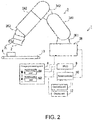
- FIG. 2 is a view showing an example of the overall configuration of the image inspecting apparatus 1.
- the image inspecting apparatus 1 includes, in addition to the camera 2 and the robot arm 3 described above, an image processing unit 8 in charge of processing of the image data sent from the camera 2, a programmable logic controller (PLC) 9 (an example of the "control part" in the disclosure) in charge of control of the camera 2 and the robot arm 3, and a robot controller 10 operating the robot arm 3 according to the instruction of the PLC 9.
- PLC programmable logic controller
- the image processing unit 8 may be, for example, a general-purpose computer having a central processing unit (CPU), a memory, an auxiliary storage apparatus (e.g., a hard disk drive, a solid state drive, etc.), and an input apparatus (a keyboard, a mouse, a touch panel, etc.), or an apparatus dedicated to image processing.
- CPU central processing unit
- memory e.g., a hard disk drive, a solid state drive, etc.
- an input apparatus a keyboard, a mouse, a touch panel, etc.
- the camera 2 has an image capturing element in which m ⁇ n light receiving elements are arrayed in a matrix, and is a device that captures a colored or monochrome, still or moving image to the image processing unit 8.
- a sensor adapted to this image may be used.
- the lighting 2L is an illumination component that illuminates the object 4 under inspection.
- the lighting 2L may be, for example, an illumination component having a single light source or may also be an illumination component having a plurality of light sources capable of respectively emitting illuminating light in different wavelengths (red light, green light, blue light) at arbitrary intensities.
- the respective single or plurality of light sources may emit light in various wavelengths, such as visible light, ultraviolet light, infrared light, etc., or may emit light in a specific wavelength.
- the lighting 2L may be an illumination component for emitting light without a shape pattern, or may be an illumination component for emitting light having a pattern of a predetermined shape.
- the robot arm 3 is a so-called multiple joint robot, and includes a first arm 3A1 connected to a base 3B via a first joint 3K1, and a second arm 3A2 connected to the tip part of the first arm 3A1 via a second joint 3K2.
- the camera 2 and the lighting 2L are provided at the tip of the second arm 3A2 via a third joint 3K3.
- a drive mechanism such as a motor, for rotating each arm around the axis of each joint is built in the robot arm 3 and operates according to the instruction sent from the robot controller 10.
- a searching part 8A (an example of the "searching part” in the disclosure) and a determining part 8B (an example of the "determining part” in the disclosure) are realized.
- the searching part 8A is mainly in charge of the image analysis for analyzing the image of the object 4 under inspection captured by the camera 2 and searching for the defect candidate 7 from the object 4 under inspection.
- the determining part 8B is mainly in charge of the process for analyzing the image of the object 4 under inspection captured by the camera 2 and determining whether the defect 6 of the object 4 under inspection is present or absent.
- the operating unit 11 is an input apparatus disposed to an appropriate place easy for the operator handling the image inspecting apparatus 1 to operate, and receives various operations performed by the operator on the image inspecting apparatus 1.
- the operating unit 11 may be a touch panel integrating the display unit 12, a keyboard commonly used for a general purpose computer, or a specifically designed input apparatus.
- the display unit 12 is a display apparatus disposed to an appropriate place easily visible for the operator handling the image inspecting apparatus 1, and displays the status of each component of the image inspecting apparatus 1, the image obtained by the camera 2, the defect candidate 7 found by the image processing unit 8, and the result of determination on whether the defect 6 is present or absent.
- the transport unit 13 includes a table or a transport mechanism for setting the object 4 under inspection and transports the object 4 under inspection according to the instruction sent from the PLC 9.
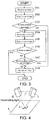
- FIG. 3 is a flowchart showing an example of a processing flow realized in the image inspecting apparatus 1.
- the PLC 9 operates the robot arm 3 so as to set the camera 2 to the position where the entire object 4 under inspection enters the field of view (S101).
- the position of the camera 2 that the PLC 9 moves by using the robot arm 3 may be a position defined in advance for each type of the object 4 under inspection, or may also be a position that is specified while analyzing the photographing condition of the object 4 under inspection in the image of the camera 2.
- the PLC 9 may also move the camera 2 to several positions where the entire object 4 under inspection can be verified by combining a plurality of images, instead of moving the camera 2 to a position where the entire object 4 under inspection is contained in one image.
- the PLC 9 causes the camera 2 to capture the image of the object 4 under inspection (S102).
- the lighting 2L illuminates the object 4 under inspection.
- the timing and the illuminance at which the lighting 2L is lit is in accordance with the instruction of the PLC 9.
- the relative positional relationship between the camera 2 and the object 4 under inspection at the time when the image is captured in Step S102 is an example of the "first image capturing condition" in the disclosure.
- the searching part 8A analyzes the image data obtained by the camera 2 in Step S102 (S103). Then, the searching part 8A searches for the defect candidate 7 from the image in which the object 4 under inspection is photographed. The searching part 8A performs the search for the defect candidate 7 according to the following method, for example.
- Step S103 for example, a spatial filter is applied to the image of the objects 4 under inspection to extract the portion with a change in the image.
- Laplacian of Gaussian can be used as the spatial filter at the time of extracting the portion with a change in the image. Then, for example, the difference between the model image stored in advance in a storage apparatus, etc., of the searching part 8A and the image of the object 4 under inspection obtained in Step S102 is derived. Then, the place where the difference is greater than a predetermined value is defined as the defect candidate 7.
- the PLC 9 moves the camera 2 to approach the defect candidate 7 by using the robot arm 3 (S104), so as to more clearly photograph the defect candidate 7 found in Step S103.
- the position of the camera 2 that the PLC 9 moves by using the robot arm 3 in Step S104 may be a position defined in advance for each position of the defect candidate 7 in the object 4 under inspection, or may also be a position specifying the position where the defect candidate 7 enters the field of view of the camera 2 in an appropriate size from the analysis result of the image of the camera 2.
- the motion of the robot arm 3 when moving the camera 2 is realized by determining the most appropriate motion of each joint after moving the camera 2 from the origin of movement to the destination of movement, and sending the signal with an amount of control according to the determined motion to each motor of the robot arm 3 by the robot controller 10 that receives the instruction from the PLC9.
- the PLC 9 causes the camera 2 to capture an image of the object 4 under inspection (S105).
- the lighting 2L illuminates the object 4 under inspection like in Step S102.
- Step S105 since the camera 2 has moved to a position closer to the defect candidate 7, in the image of the object 4 under inspection captured by the camera 2, the defect candidate 7 is photographed more clearly than in the image of the object 4 under inspection obtained by the camera 2 in Step S102.
- the relative positional relationship between the camera 2 and the object 4 under inspection at the time when the image is captured in Step S105 is an example of the "second image capturing condition" in the disclosure.
- the determining part 8B analyzes the image data obtained by the camera 2 in Step S105 (S106). Then, the determining part 8B analyzes the image of the object 4 under inspection captured by the camera 2 and determines whether the defect 6 is present or absent in the part of the defect candidate 7 photographed in the image of the object 4 under inspection. The determining part 8B determines whether the defect 6 is present or absent by using the following method.
- the determining part 8B calculates the feature value of the image at the part of the defect candidate 7 and determines whether defect candidate 7 is the defect 6.
- the feature value include, for example, a feature value enabling a binary blob analysis of circularity, perimeter, or a Feret's diameter (projection width), etc. Based on such a feature value, the determining part 8B determines whether the defect candidate 7 is the defect 6.
- Step S106 for example, whether the defect 6 is generated in the object 4 under inspection may also be detected by illuminating the object 4 under inspection with the lighting 2L and comparing the light amounts of the reflected light from the object 4 under inspection received by the respective pixels of the image capturing element of the camera 2 for the each of the pixels.
- determining the type of the defect 6 for example, based on a plurality of images captured while switching the color of the illumination light of the lighting 2L, whether the defect 6 is a color defect, whether defect 6 is an uneven defect, etc., may also be determined.
- the index used for determining the defect 6 also include, for example, the position and the size of a specific color in the image of the object 4 under inspection, in addition to comparing the light amount in each pixel and switching the color of the illuminating light.
- the determining part 8B makes an affirmative determination in Step S106.
- the PLC 9 ends the inspection of the object 4 under inspection.
- the object 4 under inspection is transferred to a predetermined place according to the inspection result.
- the determining part 8B makes a negative determination in Step S106.
- the PLC 9 determines whether another defect candidate 7 is present or absent (S107). In the case in which there is no other defect candidate 7, the PLC 9 gives a determination result that the object 4 under inspection has no abnormality in the inspection of the object 4 under inspection in the image inspecting apparatus 1 (S108). Further, in the case in which there is another defect candidate 7, the PLC 9 execute the process of Step S104 so as to clearly photograph the another defect candidate 7. As a result, whether the defect 6 is present or absent is determined for all the parts of the defect candidates 7 found in Step S103.
- the search for the defect candidate 7 suspected to have the defect 6 is firstly performed by using the image of Step S102, and in the case in which the defect candidate 7 is found, whether the defect 6 is present or absent in the part where the defect candidate 7 is found is determined by using the image of Step S105.
- Step S105 since the camera 2 has moved to a position closer to the defect candidate 7 than the position in Step S102, the resolution (an example of the "second resolution” in the disclosure) of the object 4 under inspection photographed in the image captured by the camera 2 in Step S105 is a resolution higher than the resolution (an example of the "first resolution” in the disclosure) of the object 4 under inspection photographed in the image captured by the camera 2 in Step S102, and the defect candidate 7 is more clearly photographed. Then, in the search for the defect candidate 7 performed by analyzing the image of Step S102, the high computing capacity necessary for determining the defect 6 performed by using the image of Step S105 is not required.
- Step S106 regarding the process of determining whether the defect 6 is present or absent in Step S106, which requires a computing capacity higher than that of the search for the defect candidate 7 performed in Step S103, since the process of determination for the part where the defect candidate 7 is not found is omitted, the time required for image inspection of the object 4 under inspection is shortened as compared to the case in which the determination on whether the defect 6 is present or absent is performed over the entire object 4 under inspection.
- the image inspecting apparatus 1 of the above embodiment since the appearance of the object 4 under inspection is inspected by using the camera 2 provided at the tip of the robot arm 3, the camera 2 can be moved to the appropriate position with respect to the object 4 under inspection according to the form of the object 4 under inspection. Therefore, in the case of the image inspecting apparatus 1 of the above embodiment, for example, it is possible to cope with multi-type, small-scale production while shortening the time required for image inspection.
- Step S103 the feature value of the defect candidate 7 or a value indicating the grade of the defect 6 may also be calculated.
- Examples of the feature value of the defect candidate 7 include the position of the defect candidate 7. If the position of the defect candidate 7 is calculated in Step S103, in Step S104, when the robot arm 3 is moved so that the camera 2 approaches the defect candidate 7, the position of the defect candidate 7 can be used for determining the target position which is the destination of the camera 2. Regarding the position of the defect candidate 7, for example, if the defect candidate 7 is found from the difference with respect to the reference image in which a good object under inspection without a defect is photographed, the position of the defect candidate 7 can be specified based on the position where the difference is generated in the image.
- Step S104 If the position of the defect candidate 7 is calculated in Step S103, in determining the motion of the robot arm 3 at the time of moving the camera 2 in Step S104, it is possible to promptly determine the most appropriate motion of each joint after moving the camera 2 to the position where the defect candidate 7 is clearly photographed, and send the amount of control to the motor of the robot arm 3 according to the determined motion.
- the feature value of the defect candidate 7 can also be used to determine, for example, the relative angle between the optical axis of the camera 2 and the object 4 under inspection, the relative positions between the lighting 2L and the object 4 under inspection, and the relative angle between the optical axis of the lighting 2L and the object 4 under inspection, in addition to the destination of the camera 2.
- the defect candidate 7 is photographed obliquely by the camera 2 even if the camera 2 approaches the defect candidate 7, the part of the defect candidate 7 is still not photographed clearly in the image of the camera 2.
- the position of the defect candidate 7 is calculated in Step S103, in order to clearly photograph the defect candidate 7, the normal direction at the position of the defect candidate 7 can be matched with the optical axis of the camera 2, for example.
- the positions of the camera 2 and the lighting 2L can be determined so that the defect candidate 7 is positioned on a virtual straight line that is orthogonal to another virtual straight line connecting the camera 2 and the lighting 2L and passes through a position bisecting the another virtual straight line.
- FIG. 4 is a view showing an example of the positional relationship among the camera 2, the lighting 2L, and defect 6. Depending on the material of the object 4 under inspection and the shape of the defect 6, there are cases in which the defect 6 is photographed clearly when the optical axis of the camera 2 is arranged obliquely with respect to the normal line of the part of the defect 6.
- the camera 2 and the lighting 2L may be moved so that the defect candidate 7 is positioned on the virtual straight line that is orthogonal to the another virtual straight line connecting the camera 2 and the lighting 2L and passes through the position bisecting the another virtual straight line.
- examples of the value indicating the grade of the defect 6 include a difference value between a model image of the defect candidate 7 photographed in the image captured at Step S102 and the image of the object 4 under inspection.
- the difference value is proportional to, for example, the number of pixels of the region where the difference is generated in the image, etc. If the value indicating the grade of the defect 6 is calculated in Step S103, in the case in which the defect candidates 7 are found from a plurality of places in Step S103, the process since Step S104 can be executed preferentially from the defect candidate 7 having a great value indicating the grade of the defect 6.
- Step S104 If the process since Step S104 is executed preferentially from the defect candidate 7 having a great value indicating the grade of defect 6, since the determination on whether the defect 6 is present or absent is made preferentially from the defect candidate 7 having a high possibility that the defect 6 is actually present, the image inspection of the object 4 under inspection is performed efficiently. In this case, for example, in the case in which the presence of at least one defect 6 is recognized in the object 4 under inspection, the determination on whether the defect 6 is present or absent in the parts of other defect candidates 7 can be omitted, and the inspection of the object 4 under inspection can be finished promptly.
- the part of the defect candidate 7 may also be clearly photographed by changing the setting state of the image capturing element provided in the camera 2, setting the state of the lens such as the position of the focus lens provided in the camera 2, or other means, for example.
- image capturing in Step S102 and Step S105 is performed by using one camera 2 in the above embodiment, separate cameras 2 may be used in the respective steps, for example.
- image capturing in Step S102 and image capturing in Step S105 can be performed simultaneously by using the separate cameras 2, so the inspection of the object 4 under inspection can be sped up.
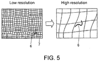
- FIG. 5 is a view showing an example of the defect 6.
- the object 4 under inspection may be subjected to fine unevenness processing for decoration, such as embossing.
- the defect 6 has a so-called scratch or dent mark.
- the scratch or dent mark can be considered as a fine recess on the surface of the defect 6.
- the unevenness of the embossing and the recess of the defect 6 essentially have similar physical properties.
- the difference, if any, is the size, the shape, the uniformity, the periodicity of the unevenness.
- a threshold is set so that scratch or dent mark can be detected with low-level image processing (e.g., LOG), part of the embossing may be erroneously detected as a defect.
- LOG low-level image processing
- To discriminate between the embossing and the scratch or dent mark it is necessary to perform an analysis by using features such as shape.
- features such as shape.
- a threshold is set to prevent occurrence of such erroneous detection, the possibility that a defect is not detected is increased.
- Step S106 in which the analysis using features such as shape is performed is not performed over the entirety of the object 4 under inspection but on the part of the defect candidate 7. Therefore, for example, in the search for the defect candidate 7 performed using the image of Step S102, by setting the threshold so that the defect 6 is not overlooked, even in the case in which the part without defect 6 is determined to be the defect candidate 7, it does not require much computing capacity and time as compared with the case in which the analysis using features such as shape is performed over the entire object 4 under inspection. Therefore, compared to the case in which the determination on presence or absence of the defect 6 is performed over the entire object 4 under inspection, the time required for the image inspection of the object 4 under inspection is shortened.
- a program for causing a computer or other machines or apparatuses (hereinafter, the computer or the like) to realize any one of the above processes can be recorded on a recording medium readable by the computer or the like, and the computer or the like reads and executes the program of the recording medium, so that the function can be provided.
- the recording medium readable by the computer or the like refers to a recording medium that can accumulate information such as data, programs, etc. by electrical, magnetic, optical, mechanical, or chemical functioning, and can be read from a computer or the like.
- recording media those that can be detached from the computer or the like include, for example, a memory card such as a flexible disk, a magneto optical disk, a CD-ROM, a CD-R/W, a DVD, a Blu-ray (Blu-ray is a registered trademark) disk, DAT, an 8-mm tape, a flash memory, etc.
- recording media fixed to the computer or the like include a hard disk, an SSD, a read only memory (ROM), etc.
Landscapes
- Engineering & Computer Science (AREA)
- Physics & Mathematics (AREA)
- General Physics & Mathematics (AREA)
- Biochemistry (AREA)
- Chemical & Material Sciences (AREA)
- General Health & Medical Sciences (AREA)
- Life Sciences & Earth Sciences (AREA)
- Immunology (AREA)
- Pathology (AREA)
- Health & Medical Sciences (AREA)
- Analytical Chemistry (AREA)
- Signal Processing (AREA)
- Computer Vision & Pattern Recognition (AREA)
- Quality & Reliability (AREA)
- Multimedia (AREA)
- Theoretical Computer Science (AREA)
- Robotics (AREA)
- Mechanical Engineering (AREA)
- Automation & Control Theory (AREA)
- Manufacturing & Machinery (AREA)
- General Engineering & Computer Science (AREA)
- Investigating Materials By The Use Of Optical Means Adapted For Particular Applications (AREA)
Abstract
Description
- The disclosure relates to an image inspecting apparatus, an image inspecting method, and an image inspecting program.
- In recent years, an image inspecting apparatus which inspects the appearance of a product by using an image has been widely used in order to automatize the inspection and save the labor in the production line (see, for example, Patent Document 1). While there are various types and methods of appearance inspection, the basic configuration is as follows. The image of an object under inspection is captured by an image capturing apparatus with a built-in image sensor, a portion serving as the inspection region is extracted from the obtained image, and the targeted inspection is performed by analyzing and evaluating the features of the image of the portion as the inspection region (e.g., judging on good/defective, sorting, obtaining information, etc.).
- In this type of image inspecting apparatus, to inspect the appearance of the object under inspection, it is necessary to capture images of the object under inspection from various directions. Also, in recent years, due to the strong need for facilitating the production efficiency in multi-type, small-scale production, it is required to appropriately change the parts of the object under inspection flowing in the production line at which images are captured according to the shape of the object under inspection, etc. Therefore, recently, in order to enable such appearance inspection, an attempt has been made to adjust the position and the orientation of the image capturing apparatus by using a robot arm according to the shape of the object under inspection, etc., in the image capturing of the object under inspection.
- [Patent Document 1] Japanese Laid-Open No.
2013-191064 - In the case in which an image capturing apparatus used for image inspection is fixed, the part where an image can be captured at the object under inspection flowing in the production line is determined naturally. Therefore, the time required for capturing an image of the object under inspection in the image inspection is basically unchanged. On the other hand, in the case in which the image of the object under inspection flowing in the production line is captured by using an image capturing apparatus attached to a robot arm, the time required for capturing an image changes according to the operation speed of the robot arm and the number of times of movement of the image capturing apparatus. Therefore, if image capturing is performed by efficiently moving the image capturing apparatus attached to the robot arm, there is a possibility that such image capturing can cope with multi-type, small-scale production and shorten the time required for capturing the image of the object under inspection as compared with the case in which the image of the object under inspection is captured by using the fixed image capturing apparatus. However, since objects that can be easily removed, such as a simply attached foreign matter, may be present on the object under inspection in addition to defects such as irreparable scratches, in the image inspection in the production line, the type of defect appearing in the image needs to be determined by performing an image analysis. In order to perform such an image analysis, it is necessary to use a high-resolution image. Therefore, if it is attempted to carry out the image analysis on the appearance of the object under inspection to the extent of every corner by using the image capturing apparatus attached to the robot arm, the number of times of movement of the image capturing apparatus and the calculation processing required for the image analysis are expected to increase.
- Therefore, the disclosure discloses a technology that makes it possible to shorten the time required for image inspection while making it possible to cope with multi-type, small-scale production.
- According to the disclosure, when an image captured under a first image capturing condition is analyzed and a defect candidate is found, an image in which a part where the defect candidate is found is photographed under a second image capturing condition clearer than the first image capturing condition is analyzed and whether a defect is present or absent is determined.
- In detail, the disclosure provides an image inspecting apparatus for inspecting an object under inspection by using an image. The image inspecting apparatus includes: at least one image capturing part which captures an image of the object under inspection; a lighting part which irradiates the object under inspection with light; a control part of image capturing condition which includes a moving part for changing a mutual relative positional relationship of at least two of the image capturing part, the object under inspection, and the lighting part; a searching part which analyzes an image captured by the image capturing part under a first image capturing condition and searches for a defect candidate from the object under inspection; and a determining part which analyzes the image captured by the image capturing part and determines whether a defect of the object under inspection is present or absent. When the searching part finds the defect candidate from the object under inspection, the control part controls an image capturing condition so that a part where the defect candidate is found by the searching part is photographed under a second image capturing condition that is clearer than the first image capturing condition. The determining part analyzes an image captured by the image capturing part under the second image capturing condition and determines whether the defect of the object under inspection is present or absent.
- Here, the object under inspection is an object to undergo image inspection performed by the image inspecting apparatus, and examples of the object under inspection include industrial products manufactured in a production line, industrial products recycled from the market, components of industrial products, agricultural products that are harvested or fishery products that are caught, and various other objects.
- Further, the image capturing condition is the condition that can affect the determination on whether the defect of the object under inspection is present or absent in the analysis of the image of the object under inspection captured by the image capturing part. Examples of those that may influence the photographing condition of the object under inspection include the relative distance and orientation between the object under inspection and the image capturing part, the setting state of an image capturing element included in the image capturing part, the state of a lens provided in the image capturing part, and various others. For example, in the case in which the object under inspection has a defect, since the relative distance between the part where the defect is present and the image capturing part becomes shorter, and the defect is photographed larger in the image, the defect is photographed clearly in the image, and the possibility that whether the defect is present or absent is erroneously determined in the image inspection decreases.
- In addition, the defect candidate refers to one that is possibly a defect in the image of the object under inspection captured under the first image capturing condition, and is not a concept intended for one that may become a defect in the future through a temporal change after the image inspection, for example.
- In the image inspecting apparatus, the search for the defect candidate suspected to have the defect is firstly performed. In the case in which the defect candidate is found, whether the defect is present or absent at the part where the defect candidate is found is determined. Since the search for the defect candidate is a process simpler than the determination on whether the defect is present or absent, the high computing capacity for analyzing the image is not required. Then, in the image inspecting apparatus, the determination on whether the defect is present or absent, which requires a higher computing capacity than that of the search for the defect candidate, is omitted for the part where the defect candidate is not found. Therefore, compared with the case in which the determination on whether the defect is present or absent is performed over the entire object under inspection, the time required for image inspection of the object under inspection can be shortened.
- According to an embodiment of the disclosure, the searching part analyzes an image captured by the image capturing part at a first resolution and searches for the defect candidate from the object under inspection, and when the searching part finds the defect candidate from the object under inspection, the control part changes a relative position of the image capturing part with respect to the object under inspection or a field of view of the image capturing part, so that the part where the defect candidate is found by the searching part is photographed at a second resolution that is a resolution higher than the first resolution.
- Here, the resolution is a quantitative representation of the fineness of the image of the object under inspection in the image captured by the image capturing part. For example, the resolution varies with the number of pixels of the image capturing element possessed by the image capturing part, the relative distance and orientation between the object under inspection and the image capturing part, the state of the lens included in the image capturing part, and various other conditions.
- If the part where the defect candidate is found is photographed at the second resolution that is a solution higher than the first resolution, since the shape of the defect, etc., can be specified from the image at the second resolution, the defect can be determined correctly.
- In addition, according to an embodiment of the disclosure, the searching part analyzes the image of the object under inspection photographed at the first resolution by moving the image capturing part to a first position by the control part and searches for the defect candidate from the object under inspection, and when the searching part finds the defect candidate from the object under inspection, the control part moves a position of the image capturing part to a second position closer to the object under inspection than the first position, so that the part where the defect candidate is found by the searching part is photographed at the second resolution.
- Here, the first position refers to a relative positional relationship of the image capturing part with respect to the object under inspection, and is an example of the first image capturing condition. Also, the second position is a relative positional relationship of the image capturing part with respect to the object under inspection, refers to a positional relationship with which the part of the defect candidate is more clearly photographed than the case in which the image capturing part captures the image of the object under inspection at the first position, and is an example of the second image capturing condition.
- If the position of the image capturing part with respect to the object under inspection is closer at the second position which is the positional relationship at the time when the image used for the determining part to determine whether the defect is present or absent is obtained than at the first position which is the positional relationship at the time when the image used for the searching part to search for the defect candidate is obtained, since the part of the defect candidate is photographed more clearly in the image captured at the second position than the image captured at the first position, the defect can be determined more correctly.
- In addition, according to an embodiment of the disclosure, the searching part calculates a feature value of the defect candidate including a position of the defect candidate when finding the defect candidate from the object under inspection, and when the searching part finds the defect candidate from the object under inspection, the control part changes at least one of a relative angle between an optical axis of the image capturing part and the object under inspection, relative positions between the lighting part and the object under inspection, and a relative angle between the optical axis of the lighting part and the object under inspection based on the feature value calculated by the searching part, so that the part where the defect candidate is found by the searching part is photographed under the second image capturing condition.
- Here, the feature value of the defect candidate is a value quantitatively indicating a feature related to the defect candidate in the image captured under the first image capturing condition, and includes the position of the defect candidate, for example. Such a feature value can be obtained from a difference with respect to a reference image in which a good object under inspection without a defect is photographed, for example. If such a feature value is obtained from the image captured under the first image capturing condition, the relative positional relationship between the image capturing part, the lighting part and the object under inspection under the second image capturing condition can be appropriately determined.
- Further, according to an embodiment of the disclosure, the searching part analyzes an image captured by a first image capturing part under the first image capturing condition and searches for the defect candidate from the object under inspection, and when the searching part finds the defect candidate from the object under inspection, the control part controls the image capturing condition so that the part where the defect candidate is found by the searching part is photographed under the second image capturing condition in an image captured by a second image capturing part different from the first image capturing part. If the image capturing part that captures the image of the object under inspection under the second image capturing condition is prepared separately from the image capturing part that captures the image of the object under inspection under the first image capturing condition, the inspection can be further sped up.
- In addition, according to an embodiment of the disclosure, when the searching part finds a plurality of defect candidates from the object under inspection, the control part controls the image capturing condition, so that a part of a candidate whose value indicating a grade of a defect is great, among the defect candidates found by the searching part, is preferentially photographed under the second image capturing condition.
- Here, the value indicating the grade of the defect is a value quantitatively indicating how high the probability is that the defect candidate is a defect in the image captured under the first image capturing condition, and can be obtained from the difference with respect to a reference image in which a good object under inspection without a defect is photographed. If the image of the part of the defect whose value indicating the grade of the defect is great is preferentially captured under the second image capturing condition and the image is used to determine the defect, since the determination on whether the defect is present or absent is made preferentially from the part having a high possibility to be a defect, the determination on whether the defect is present or absent is performed more efficiently.
- In addition, according to an embodiment of the disclosure, in a case in which a defect is present in an image in which at least one of the defect candidates found by the searching part is photographed, the determining part omits analyses of images in which other defect candidates are photographed. In the case in which the presence of at least one defect is recognized in the object under inspection, the analyses on the parts of other defect candidates can be omitted, and the inspection of the object under inspection can be finished promptly.
- In addition, the disclosure can also be understood from the aspects of a method and a program. For example, the disclosure discloses an image inspecting method for inspecting an object under inspection by using an image. It may also be that the image inspecting method includes: a searching process for analyzing an image captured under a first image capturing condition by an image capturing part that captures an image of the object under inspection and searching for a defect candidate from the object under inspection; a controlling process for controlling an image capturing condition by a control part of image capturing condition including a moving part for changing a mutual relative positional relationship of at least two of the image capturing part, the object under inspection, and a lighting part which irradiates the object under inspection with light, so that when the defect candidate is found from the object under inspection in the searching process, a part where the defect candidate is found in the searching process is photographed under a second image capturing condition clearer than the first image capturing condition; and a determining process for analyzing an image captured by the image capturing part under the second image capturing condition and determining whether a defect of the object under inspection is present or absent.
- With the image inspecting apparatus, the image inspecting method and the image inspecting program, it is possible to cope with multi-type, small-scale production while shortening the time required for image inspection.
-
-
FIG. 1 is a schematic view showing an example of an operation realized by an image inspecting apparatus according to an embodiment. -
FIG. 2 is a view showing an example of an overall configuration of an image inspecting apparatus. -
FIG. 3 is a flowchart showing an example of a processing flow realized in an image inspecting apparatus. -
FIG. 4 is a view showing an example of a positional relationship among a camera, a lighting, and a defect. -
FIG. 5 is a view showing an example of defect. - <Application example>
FIG. 1 is a schematic diagram showing an example of the operation realized by animage inspecting apparatus 1 according to the embodiment. As shown inFIG. 1 , theimage inspecting apparatus 1 includes a camera 2 (an example of the "image capturing part" in the disclosure) and a robot arm 3 (an example of the "moving part" in the disclosure), for example, as the main configuration. Thecamera 2 obtains an image used for inspecting an object 4 under inspection. Therobot arm 3 is an industrial robot arm in which thecamera 2 is installed to the tip of the arm, and therobot arm 3 operates according to a control signal sent from a control apparatus (not shown). Therefore, by operating therobot arm 3, thecamera 2 can move relatively to an appropriate position with respect to the object 4 under inspection. In addition, a lighting for illuminating the object 4 under inspection may be integrated with thecamera 2, or the lighting may be attached to the tip of therobot arm 3 separately from thecamera 2. - The image data obtained by capturing the image of the object 4 under inspection by the
camera 2 is sent to an image processing unit (not shown) provided in theimage inspecting apparatus 1. In the image processing unit, an image analysis of the object 4 under inspection using the image data sent from thecamera 2 is carried out. The object 4 under inspection for which whether adefect 6 is present or absent is verified by the image processing unit is sent to the next process. Examples of thedefect 6 whose presence or absence is verified by the image processing unit include uneven defects such as dent marks caused by collision of articles with the object 4 under inspection, color defects caused by defects in the surface treatment such as painting, attached foreign matters, and various other defects. Some of these examples of thedefect 6 are easy to treat while others are irreparable. For example, if thedefect 6 detected in the inspection on the appearance of the object 4 under inspection by using the image is simply an attached foreign matter, thedefect 6 can be eliminated by removing the foreign matter. Therefore, the destination of the object 4 under inspection which has been inspected by theimage inspecting apparatus 1 may be switched according to the presence or absence of thedefect 6 and the type of thedefect 6. - In the
image inspecting apparatus 1 so configured, for example, the image of the object 4 under inspection is captured in a state in which thecamera 2 is disposed at a position where the entire object 4 under inspection enters the field ofview 5 of thecamera 2 by using therobot arm 3. Then, when adefect candidate 7 suspected to have thedefect 6 is found in the image captured at the position where the entire object 4 under inspection enters the field ofview 5 of thecamera 2, thecamera 2 is moved by therobot arm 3 and captures the image of the part of thedefect candidate 7 again, so as to more clearly photograph the part of thedefect candidate 7. Then, theimage inspecting apparatus 1 performs inspection by using the image in which the part of thedefect candidate 7 is photographed and determines whether thedefect 6 is present or absent. - The
defect 6 includes various forms as described above. Therefore, in the process of determining whether thedefect 6 is present or absent, it is necessary to perform an image analysis using various features, such as shape or color, texture, three-dimensional shape such as unevenness, etc., of thedefect 6 photographed in the image. Therefore, in the process of determining whether thedefect 6 is present or absent, the image in which thedefect 6 is photographed is required to have a sufficient resolution so as to extract the feature such as the shape of thedefect 6. Also, in order to analyze the image at such a resolution, a high computing capacity is required. Therefore, in the case in which the determination on whether thedefect 6 is present or absent is performed over the entire object 4 under inspection, in order to obtain an image at the sufficient resolution so as to extract the feature such as the shape of thedefect 6, a plurality of images of the object 4 under inspection captured from various viewpoints are required. Also, to analyze all these images, a tremendous amount of computing capacity is required. - In this regard, in the
image inspecting apparatus 1 of this embodiment, a search for thedefect candidate 7 suspected to have thedefect 6 is firstly performed, as described above. In the case in which thedefect candidate 7 is found, whether thedefect 6 is present or absent at the part where thedefect candidate 7 is found is determined. Since the search for thedefect candidate 7 does not require extraction of the feature such as the shape of thedefect 6, the resolution is lower than the resolution of the image used for determining whether thedefect 6 is present or absent, and the high computing capacity for analyzing the image is not required. Then, in theimage inspecting apparatus 1, the determination on whether thedefect 6 is present or absent, which requires a higher computing capacity for a higher resolution than that of the search for thedefect candidate 7, is omitted for the part where thedefect candidate 7 is not found. Therefore, compared with the case in which the determination on whether thedefect 6 is present or absent is performed over the entire object 4 under inspection, the time required for image inspection of the object 4 under inspection can be shortened. - Incidentally, the
image inspecting apparatus 1 may also perform the search for thedefect candidate 7 by using an image in which a portion of the object 4 under inspection is photographed, for example, instead of using the image captured when thecamera 2 is positioned at the position where the entire object 4 under inspection enters the field of view. In addition, the determination by theimage inspecting apparatus 1 on whether thedefect 6 is present or absent by using the image in which the part of thedefect candidate 7 is photographed may be performed by using an image that is photographed more clearly by changing the field of view of thecamera 2, for example, instead of using an image that is photographed more clearly through moving thecamera 2 by therobot arm 3. - In the
image inspecting apparatus 1, for example, the phase shift method or various other three-dimensional measurement methods can be applied. Theimage inspecting apparatus 1 can be used, for example, as one of the FA apparatuses used in the production line for manufacturing automobiles or various other industrial products. - <Embodiment> The
image inspecting apparatus 1 will be described in detail below.FIG. 2 is a view showing an example of the overall configuration of theimage inspecting apparatus 1. Theimage inspecting apparatus 1 includes, in addition to thecamera 2 and therobot arm 3 described above, an image processing unit 8 in charge of processing of the image data sent from thecamera 2, a programmable logic controller (PLC) 9 (an example of the "control part" in the disclosure) in charge of control of thecamera 2 and therobot arm 3, and arobot controller 10 operating therobot arm 3 according to the instruction of thePLC 9. The image processing unit 8 may be, for example, a general-purpose computer having a central processing unit (CPU), a memory, an auxiliary storage apparatus (e.g., a hard disk drive, a solid state drive, etc.), and an input apparatus (a keyboard, a mouse, a touch panel, etc.), or an apparatus dedicated to image processing. The same applies for thePLC 9 and therobot controller 10. - The
camera 2 has an image capturing element in which m×n light receiving elements are arrayed in a matrix, and is a device that captures a colored or monochrome, still or moving image to the image processing unit 8. However, in the case in which a special image (X-ray image, thermo image, etc.) other than a visible light image is used for inspection, a sensor adapted to this image may be used. - A
lighting 2L is provided along with thecamera 2. Thelighting 2L is an illumination component that illuminates the object 4 under inspection. Thelighting 2L may be, for example, an illumination component having a single light source or may also be an illumination component having a plurality of light sources capable of respectively emitting illuminating light in different wavelengths (red light, green light, blue light) at arbitrary intensities. The respective single or plurality of light sources may emit light in various wavelengths, such as visible light, ultraviolet light, infrared light, etc., or may emit light in a specific wavelength. Moreover, thelighting 2L may be an illumination component for emitting light without a shape pattern, or may be an illumination component for emitting light having a pattern of a predetermined shape. - The
robot arm 3 is a so-called multiple joint robot, and includes a first arm 3A1 connected to abase 3B via a first joint 3K1, and a second arm 3A2 connected to the tip part of the first arm 3A1 via a second joint 3K2. Thecamera 2 and thelighting 2L are provided at the tip of the second arm 3A2 via a third joint 3K3. A drive mechanism, such as a motor, for rotating each arm around the axis of each joint is built in therobot arm 3 and operates according to the instruction sent from therobot controller 10. - In the image processing unit 8, with the CPU executing a computer program (an example of the "image inspecting program" in the disclosure) developed in the memory, a searching
part 8A (an example of the "searching part" in the disclosure) and a determiningpart 8B (an example of the "determining part" in the disclosure) are realized. The searchingpart 8A is mainly in charge of the image analysis for analyzing the image of the object 4 under inspection captured by thecamera 2 and searching for thedefect candidate 7 from the object 4 under inspection. The determiningpart 8B is mainly in charge of the process for analyzing the image of the object 4 under inspection captured by thecamera 2 and determining whether thedefect 6 of the object 4 under inspection is present or absent. - An operating
unit 11, adisplay unit 12, and atransport unit 13 are provided in theimage inspecting apparatus 1. The operatingunit 11 is an input apparatus disposed to an appropriate place easy for the operator handling theimage inspecting apparatus 1 to operate, and receives various operations performed by the operator on theimage inspecting apparatus 1. The operatingunit 11 may be a touch panel integrating thedisplay unit 12, a keyboard commonly used for a general purpose computer, or a specifically designed input apparatus. Thedisplay unit 12 is a display apparatus disposed to an appropriate place easily visible for the operator handling theimage inspecting apparatus 1, and displays the status of each component of theimage inspecting apparatus 1, the image obtained by thecamera 2, thedefect candidate 7 found by the image processing unit 8, and the result of determination on whether thedefect 6 is present or absent. Thetransport unit 13 includes a table or a transport mechanism for setting the object 4 under inspection and transports the object 4 under inspection according to the instruction sent from thePLC 9. - The processing flow realized in the
image inspecting apparatus 1 will be described below. -
FIG. 3 is a flowchart showing an example of a processing flow realized in theimage inspecting apparatus 1. When the image inspection is started at theimage inspecting apparatus 1, thePLC 9 operates therobot arm 3 so as to set thecamera 2 to the position where the entire object 4 under inspection enters the field of view (S101). In Step S101, the position of thecamera 2 that thePLC 9 moves by using therobot arm 3 may be a position defined in advance for each type of the object 4 under inspection, or may also be a position that is specified while analyzing the photographing condition of the object 4 under inspection in the image of thecamera 2. Also, thePLC 9 may also move thecamera 2 to several positions where the entire object 4 under inspection can be verified by combining a plurality of images, instead of moving thecamera 2 to a position where the entire object 4 under inspection is contained in one image. - When the
camera 2 is moved to the position where the entire object 4 under inspection enters the field of view under the control of thePLC 9, thePLC 9 causes thecamera 2 to capture the image of the object 4 under inspection (S102). When thecamera 2 captures the image of the object 4 under inspection, thelighting 2L illuminates the object 4 under inspection. The timing and the illuminance at which thelighting 2L is lit is in accordance with the instruction of thePLC 9. The relative positional relationship between thecamera 2 and the object 4 under inspection at the time when the image is captured in Step S102 is an example of the "first image capturing condition" in the disclosure. - When the
camera 2 captures the image of the entire object 4 under inspection under the control of thePLC 9, the searchingpart 8A analyzes the image data obtained by thecamera 2 in Step S102 (S103). Then, the searchingpart 8A searches for thedefect candidate 7 from the image in which the object 4 under inspection is photographed. The searchingpart 8A performs the search for thedefect candidate 7 according to the following method, for example. - For example, in the case in which the object 4 under inspection photographed in the image obtained by the
camera 2 has no defect, there is no difference generated even if the image of thecamera 2 is compared with the reference image in which a good object 4 under inspection without thedefect 6 is photographed. On the other hand, in the case in which the object 4 under inspection photographed the image obtained by thecamera 2 has thedefect 6, a difference is generated by comparing the image of thecamera 2 with the reference image in which a good object 4 under inspection without thedefect 6 is photographed. Therefore, in the analysis of Step S103, for example, a spatial filter is applied to the image of the objects 4 under inspection to extract the portion with a change in the image. For example, Laplacian of Gaussian (LOG) can be used as the spatial filter at the time of extracting the portion with a change in the image. Then, for example, the difference between the model image stored in advance in a storage apparatus, etc., of the searchingpart 8A and the image of the object 4 under inspection obtained in Step S102 is derived. Then, the place where the difference is greater than a predetermined value is defined as thedefect candidate 7. - When the
defect candidate 7 is found from the image of the object 4 under inspection by such a process, thePLC 9 moves thecamera 2 to approach thedefect candidate 7 by using the robot arm 3 (S104), so as to more clearly photograph thedefect candidate 7 found in Step S103. The position of thecamera 2 that thePLC 9 moves by using therobot arm 3 in Step S104 may be a position defined in advance for each position of thedefect candidate 7 in the object 4 under inspection, or may also be a position specifying the position where thedefect candidate 7 enters the field of view of thecamera 2 in an appropriate size from the analysis result of the image of thecamera 2. The motion of therobot arm 3 when moving thecamera 2 is realized by determining the most appropriate motion of each joint after moving thecamera 2 from the origin of movement to the destination of movement, and sending the signal with an amount of control according to the determined motion to each motor of therobot arm 3 by therobot controller 10 that receives the instruction from the PLC9. - When the
camera 2 moves to a position close to thedefect candidate 7 under the control of thePLC 9, thePLC 9 causes thecamera 2 to capture an image of the object 4 under inspection (S105). When thecamera 2 captures the image of the object 4 under inspection, thelighting 2L illuminates the object 4 under inspection like in Step S102. In Step S105, since thecamera 2 has moved to a position closer to thedefect candidate 7, in the image of the object 4 under inspection captured by thecamera 2, thedefect candidate 7 is photographed more clearly than in the image of the object 4 under inspection obtained by thecamera 2 in Step S102. The relative positional relationship between thecamera 2 and the object 4 under inspection at the time when the image is captured in Step S105 is an example of the "second image capturing condition" in the disclosure. - When the image of the part of the
defect candidate 7 is captured by thecamera 2 under the control of thePLC 9, the determiningpart 8B analyzes the image data obtained by thecamera 2 in Step S105 (S106). Then, the determiningpart 8B analyzes the image of the object 4 under inspection captured by thecamera 2 and determines whether thedefect 6 is present or absent in the part of thedefect candidate 7 photographed in the image of the object 4 under inspection. The determiningpart 8B determines whether thedefect 6 is present or absent by using the following method. - That is, the determining
part 8B calculates the feature value of the image at the part of thedefect candidate 7 and determines whetherdefect candidate 7 is thedefect 6. Examples of the feature value include, for example, a feature value enabling a binary blob analysis of circularity, perimeter, or a Feret's diameter (projection width), etc. Based on such a feature value, the determiningpart 8B determines whether thedefect candidate 7 is thedefect 6. - Regarding the light amount of the reflected light from the object 4 under inspection received by each pixel of the image capturing element of the
camera 2, for pixels corresponding to a color defect, an uneven defect, the place where a foreign matter is attached, etc., a difference is generated by comparing with the surrounding pixels. Therefore, in the analysis of Step S106, for example, whether thedefect 6 is generated in the object 4 under inspection may also be detected by illuminating the object 4 under inspection with thelighting 2L and comparing the light amounts of the reflected light from the object 4 under inspection received by the respective pixels of the image capturing element of thecamera 2 for the each of the pixels. Further, in determining the type of thedefect 6, for example, based on a plurality of images captured while switching the color of the illumination light of thelighting 2L, whether thedefect 6 is a color defect, whetherdefect 6 is an uneven defect, etc., may also be determined. Examples of the index used for determining thedefect 6 also include, for example, the position and the size of a specific color in the image of the object 4 under inspection, in addition to comparing the light amount in each pixel and switching the color of the illuminating light. - When the
defect 6 is photographed in the image captured in Step S105, the determiningpart 8B makes an affirmative determination in Step S106. When the determiningpart 8B makes the affirmative determination in Step S106, thePLC 9 ends the inspection of the object 4 under inspection. When thePLC 9 ends the inspection of the object 4 under inspection, the object 4 under inspection is transferred to a predetermined place according to the inspection result. In addition, if thedefect 6 is not photographed in the image captured in Step S105, the determiningpart 8B makes a negative determination in Step S106. - Also, when the determining
part 8B makes a negative determination in Step S106, thePLC 9 determines whether anotherdefect candidate 7 is present or absent (S107). In the case in which there is noother defect candidate 7, thePLC 9 gives a determination result that the object 4 under inspection has no abnormality in the inspection of the object 4 under inspection in the image inspecting apparatus 1 (S108). Further, in the case in which there is anotherdefect candidate 7, thePLC 9 execute the process of Step S104 so as to clearly photograph the anotherdefect candidate 7. As a result, whether thedefect 6 is present or absent is determined for all the parts of thedefect candidates 7 found in Step S103. - In the
image inspecting apparatus 1 of the above embodiment, the search for thedefect candidate 7 suspected to have thedefect 6 is firstly performed by using the image of Step S102, and in the case in which thedefect candidate 7 is found, whether thedefect 6 is present or absent in the part where thedefect candidate 7 is found is determined by using the image of Step S105. Then, in Step S105, since thecamera 2 has moved to a position closer to thedefect candidate 7 than the position in Step S102, the resolution (an example of the "second resolution" in the disclosure) of the object 4 under inspection photographed in the image captured by thecamera 2 in Step S105 is a resolution higher than the resolution (an example of the "first resolution" in the disclosure) of the object 4 under inspection photographed in the image captured by thecamera 2 in Step S102, and thedefect candidate 7 is more clearly photographed. Then, in the search for thedefect candidate 7 performed by analyzing the image of Step S102, the high computing capacity necessary for determining thedefect 6 performed by using the image of Step S105 is not required. Therefore, in the case of theimage inspecting apparatus 1 of the above embodiment, regarding the process of determining whether thedefect 6 is present or absent in Step S106, which requires a computing capacity higher than that of the search for thedefect candidate 7 performed in Step S103, since the process of determination for the part where thedefect candidate 7 is not found is omitted, the time required for image inspection of the object 4 under inspection is shortened as compared to the case in which the determination on whether thedefect 6 is present or absent is performed over the entire object 4 under inspection. - In the
image inspecting apparatus 1 of the above embodiment, since the appearance of the object 4 under inspection is inspected by using thecamera 2 provided at the tip of therobot arm 3, thecamera 2 can be moved to the appropriate position with respect to the object 4 under inspection according to the form of the object 4 under inspection. Therefore, in the case of theimage inspecting apparatus 1 of the above embodiment, for example, it is possible to cope with multi-type, small-scale production while shortening the time required for image inspection. - It should be noted that, in Step S103, the feature value of the
defect candidate 7 or a value indicating the grade of thedefect 6 may also be calculated. - Examples of the feature value of the
defect candidate 7 include the position of thedefect candidate 7. If the position of thedefect candidate 7 is calculated in Step S103, in Step S104, when therobot arm 3 is moved so that thecamera 2 approaches thedefect candidate 7, the position of thedefect candidate 7 can be used for determining the target position which is the destination of thecamera 2. Regarding the position of thedefect candidate 7, for example, if thedefect candidate 7 is found from the difference with respect to the reference image in which a good object under inspection without a defect is photographed, the position of thedefect candidate 7 can be specified based on the position where the difference is generated in the image. If the position of thedefect candidate 7 is calculated in Step S103, in determining the motion of therobot arm 3 at the time of moving thecamera 2 in Step S104, it is possible to promptly determine the most appropriate motion of each joint after moving thecamera 2 to the position where thedefect candidate 7 is clearly photographed, and send the amount of control to the motor of therobot arm 3 according to the determined motion. - Also, if the position of the
defect candidate 7 is calculated as the feature value of thedefect candidate 7, the feature value of thedefect candidate 7 can also be used to determine, for example, the relative angle between the optical axis of thecamera 2 and the object 4 under inspection, the relative positions between thelighting 2L and the object 4 under inspection, and the relative angle between the optical axis of thelighting 2L and the object 4 under inspection, in addition to the destination of thecamera 2. In the case in which thedefect candidate 7 is photographed obliquely by thecamera 2 even if thecamera 2 approaches thedefect candidate 7, the part of thedefect candidate 7 is still not photographed clearly in the image of thecamera 2. In this regard, if the position of thedefect candidate 7 is calculated in Step S103, in order to clearly photograph thedefect candidate 7, the normal direction at the position of thedefect candidate 7 can be matched with the optical axis of thecamera 2, for example. - Also, if the position of the
defect candidate 7 is calculated in Step S103, in order to clearly photograph thedefect candidate 7, for example, the positions of thecamera 2 and thelighting 2L can be determined so that thedefect candidate 7 is positioned on a virtual straight line that is orthogonal to another virtual straight line connecting thecamera 2 and thelighting 2L and passes through a position bisecting the another virtual straight line.FIG. 4 is a view showing an example of the positional relationship among thecamera 2, thelighting 2L, anddefect 6. Depending on the material of the object 4 under inspection and the shape of thedefect 6, there are cases in which thedefect 6 is photographed clearly when the optical axis of thecamera 2 is arranged obliquely with respect to the normal line of the part of thedefect 6. Therefore, when determining the destination of thecamera 2 in Step S104, as shown inFIG. 4 for example, in order for thecamera 2 to clearly photograph thedefect 6 illuminated by thelighting 2L, thecamera 2 and thelighting 2L may be moved so that thedefect candidate 7 is positioned on the virtual straight line that is orthogonal to the another virtual straight line connecting thecamera 2 and thelighting 2L and passes through the position bisecting the another virtual straight line. - Further, examples of the value indicating the grade of the
defect 6 include a difference value between a model image of thedefect candidate 7 photographed in the image captured at Step S102 and the image of the object 4 under inspection. The difference value is proportional to, for example, the number of pixels of the region where the difference is generated in the image, etc. If the value indicating the grade of thedefect 6 is calculated in Step S103, in the case in which thedefect candidates 7 are found from a plurality of places in Step S103, the process since Step S104 can be executed preferentially from thedefect candidate 7 having a great value indicating the grade of thedefect 6. If the process since Step S104 is executed preferentially from thedefect candidate 7 having a great value indicating the grade ofdefect 6, since the determination on whether thedefect 6 is present or absent is made preferentially from thedefect candidate 7 having a high possibility that thedefect 6 is actually present, the image inspection of the object 4 under inspection is performed efficiently. In this case, for example, in the case in which the presence of at least onedefect 6 is recognized in the object 4 under inspection, the determination on whether thedefect 6 is present or absent in the parts ofother defect candidates 7 can be omitted, and the inspection of the object 4 under inspection can be finished promptly. - Also, even though the part of the
defect candidate 7 is clearly photographed by moving the position of thecamera 2 to capture the image more closely inStep 105 than in Step S102 in the above embodiment, the part of thedefect candidate 7 may also be clearly photographed by changing the setting state of the image capturing element provided in thecamera 2, setting the state of the lens such as the position of the focus lens provided in thecamera 2, or other means, for example. - Even though image capturing in Step S102 and Step S105 is performed by using one
camera 2 in the above embodiment,separate cameras 2 may be used in the respective steps, for example. In this case, image capturing in Step S102 and image capturing in Step S105 can be performed simultaneously by using theseparate cameras 2, so the inspection of the object 4 under inspection can be sped up. -
FIG. 5 is a view showing an example of thedefect 6. For example, the object 4 under inspection may be subjected to fine unevenness processing for decoration, such as embossing. Meanwhile, as described above, thedefect 6 has a so-called scratch or dent mark. The scratch or dent mark can be considered as a fine recess on the surface of thedefect 6. In other words, the unevenness of the embossing and the recess of thedefect 6 essentially have similar physical properties. The difference, if any, is the size, the shape, the uniformity, the periodicity of the unevenness. Therefore, for example, if a threshold is set so that scratch or dent mark can be detected with low-level image processing (e.g., LOG), part of the embossing may be erroneously detected as a defect. To discriminate between the embossing and the scratch or dent mark, it is necessary to perform an analysis by using features such as shape. However, for this purpose, it is necessary to obtain images with a sufficient resolution, and a high computing capacity is required. Therefore, if such processing is performed over the entirety of the object 4 under inspection by using the image in which the object 4 under inspection is photographed, tremendous computing capacity and time are required. Further, if a threshold is set to prevent occurrence of such erroneous detection, the possibility that a defect is not detected is increased. - In this regard, in the
image inspecting apparatus 1 of the above embodiment, Step S106 in which the analysis using features such as shape is performed is not performed over the entirety of the object 4 under inspection but on the part of thedefect candidate 7. Therefore, for example, in the search for thedefect candidate 7 performed using the image of Step S102, by setting the threshold so that thedefect 6 is not overlooked, even in the case in which the part withoutdefect 6 is determined to be thedefect candidate 7, it does not require much computing capacity and time as compared with the case in which the analysis using features such as shape is performed over the entire object 4 under inspection. Therefore, compared to the case in which the determination on presence or absence of thedefect 6 is performed over the entire object 4 under inspection, the time required for the image inspection of the object 4 under inspection is shortened. - <Computer-Readable Recording Medium> A program for causing a computer or other machines or apparatuses (hereinafter, the computer or the like) to realize any one of the above processes can be recorded on a recording medium readable by the computer or the like, and the computer or the like reads and executes the program of the recording medium, so that the function can be provided.
- Here, the recording medium readable by the computer or the like refers to a recording medium that can accumulate information such as data, programs, etc. by electrical, magnetic, optical, mechanical, or chemical functioning, and can be read from a computer or the like. Among such recording media, those that can be detached from the computer or the like include, for example, a memory card such as a flexible disk, a magneto optical disk, a CD-ROM, a CD-R/W, a DVD, a Blu-ray (Blu-ray is a registered trademark) disk, DAT, an 8-mm tape, a flash memory, etc. In addition, recording media fixed to the computer or the like include a hard disk, an SSD, a read only memory (ROM), etc.
-
- 1
- image inspecting apparatus
- 2
- camera
- 2L
- lighting
- 3
- robot arm
- 3K1
- first joint
- 3K2
- second joint
- 3K3
- third joint
- 3B
- base
- 3A1
- first arm
- 3A2
- second arm
- 4
- object under inspection
- 5
- field of view
- 6
- defect
- 7
- defect candidate
- 8
- image processing unit
- 8A
- searching part
- 8B
- determining part
- 9
- PLC
- 10
- robot controller
- 11
- operating unit
- 12
- display unit
- 13
- transport unit
- S101, S102, S103, S104, S105, S106, S107, S108
- step
Claims (9)
- An image inspecting apparatus (1) for inspecting an object (4) under inspection by using an image, characterized in that, the image inspecting apparatus (1) comprising:at least one image capturing part (2) which captures an image of the object (4) under inspection;a lighting part (2L) which irradiates the object (4) under inspection with light;a control part (9) of image capturing condition which comprises a moving part (3) for changing a mutual relative positional relationship of at least two of the image capturing part (2), the object (4) under inspection, and the lighting part (2L);a searching part (8A) which analyzes an image captured by the image capturing part (2) under a first image capturing condition and searches for a defect candidate (7) from the object (4) under inspection; anda determining part (8B) which analyzes the image captured by the image capturing part (2) and determines whether a defect (6) of the object (4) under inspection is present or absent,wherein when the searching part (8A) finds the defect candidate (7) from the object (4) under inspection, the control part (9) controls an image capturing condition such that a part where the defect candidate (7) is found by the searching part (8A) is photographed under a second image capturing condition that is clearer than the first image capturing condition, and
wherein the determining part (8B) analyzes an image captured by the image capturing part (2) under the second image capturing condition and determines whether the defect (6) of the object (4) under inspection is present or absent. - The image inspecting apparatus (1) according to claim 1,
wherein the searching part (8A) analyzes an image captured by the image capturing part (2) at a first resolution and searches for the defect candidate (7) from the object (4) under inspection, and
wherein when the searching part (8A) finds the defect candidate (7) from the object (4) under inspection, the control part (9) changes a relative position of the image capturing part (2) with respect to the object (4) under inspection or a field of view (5) of the image capturing part (2), such that the part where the defect candidate (7) is found by the searching part (8A) is photographed at a second resolution that is a resolution higher than the first resolution. - The image inspecting apparatus (1) according to claim 2,
wherein the searching part (8A) analyzes the image of the object (4) under inspection photographed at the first resolution by moving the image capturing part (2) to a first position by the control part (9) and searches for the defect candidate (7) from the object (4) under inspection, and
wherein when the searching part (8A) finds the defect candidate (7) from the object (4) under inspection, the control part (9) moves a position of the image capturing part (2) to a second position closer to the object (4) under inspection than the first position, such that the part where the defect candidate (7) is found by the searching part (8A) is photographed at the second resolution. - The image inspecting apparatus (1) according to claim 1,
wherein the searching part (8A) calculates a feature value of the defect candidate (7) comprising a position of the defect candidate (7) when finding the defect candidate (7) from the object (4) under inspection, and
wherein when the searching part (8A) finds the defect candidate (7) from the object (4) under inspection, the control part (9) changes at least one of a relative angle between an optical axis of the image capturing part (2) and the object (4) under inspection, relative positions between the lighting part (2L) and the object (4) under inspection, and a relative angle between an optical axis of the lighting part (2L) and the object (4) under inspection based on the feature value calculated by the searching part (8A), such that the part where the defect candidate (7) is found by the searching part (8A) is photographed under the second image capturing condition. - The image inspecting apparatus (1) according to claim 1,
wherein the searching part (8A) analyzes an image captured by a first image capturing part under the first image capturing condition and searches for the defect candidate (7) from the object (4) under inspection, and
wherein when the searching part (8A) finds the defect candidate (7) from the object (4) under inspection, the control part (9) controls the image capturing condition such that the part where the defect candidate (7) is found by the searching part (8A) is photographed under the second image capturing condition in an image captured by a second image capturing part different from the first image capturing part. - The image inspecting apparatus (1) according to any one of claims 1 to 5,
wherein when the searching part (8A) finds a plurality of defect candidates (7) from the object (4) under inspection, the control part (9) controls the image capturing condition, such that a part of a candidate whose value indicating a grade of a defect (6) is great, among the defect candidates (7) found by the searching part (8A), is preferentially photographed under the second image capturing condition. - The image inspecting apparatus (1) according to claim 6,
wherein in a case in which a defect (6) is present in an image in which at least one of the defect candidates (7) found by the searching part (8A) is photographed, the determining part (8B) omits analyses of images in which other defect candidates (7) are photographed. - An image inspecting method for inspecting an object (4) under inspection by using an image, characterized in that, the image inspecting method comprising:a searching process for analyzing an image captured under a first image capturing condition by an image capturing part (2) that captures an image of the object (4) under inspection and searching for a defect candidate (7) from the object (4) under inspection;a control process for controlling an image capturing condition by a control part (9) of image capturing condition comprising a moving part (3) for changing a mutual relative positional relationship of at least two of the image capturing part (2), the object (4) under inspection, and a lighting part (2L) which irradiates the object (4) under inspection with light, such that when the defect candidate (7) is found from the object (4) under inspection in the searching process, a part where the defect candidate (7) is found in the searching process is photographed under a second image capturing condition clearer than the first image capturing condition; anda determining process for analyzing an image captured by the image capturing part (2) under the second image capturing condition and determining whether a defect (6) of the object (4) under inspection is present or absent.
- An image inspecting program for inspecting an object (4) under inspection by using an image, characterized in that, the image inspecting program causing a computer to execute following:a searching process for analyzing an image captured under a first image capturing condition by an image capturing part (2) that captures an image of the object (4) under inspection and searching for a defect candidate (7) from the object (4) under inspection;a control process for controlling an image capturing condition by a control part (9) of image capturing condition comprising a moving part (3) for changing a mutual relative positional relationship of at least two of the image capturing part (2), the object (4) under inspection, and a lighting part (2L) which irradiates the object (4) under inspection with light, such that when the defect candidate (7) is found from the object (4) under inspection in the searching process, a part where the defect candidate (7) is found in the searching process is photographed under a second image capturing condition clearer than the first image capturing condition; anda determining process for analyzing an image captured by the image capturing part (2) under the second image capturing condition and determining whether a defect (6) of the object (4) under inspection is present or absent.
Applications Claiming Priority (1)
| Application Number | Priority Date | Filing Date | Title |
|---|---|---|---|
| JP2018038540A JP7073785B2 (en) | 2018-03-05 | 2018-03-05 | Image inspection equipment, image inspection method and image inspection program |
Publications (1)
| Publication Number | Publication Date |
|---|---|
| EP3537136A1 true EP3537136A1 (en) | 2019-09-11 |
Family
ID=64665440
Family Applications (1)
| Application Number | Title | Priority Date | Filing Date |
|---|---|---|---|
| EP18212346.3A Withdrawn EP3537136A1 (en) | 2018-03-05 | 2018-12-13 | Image inspecting apparatus, image inspecting method and image inspecting program |
Country Status (4)
| Country | Link |
|---|---|
| US (1) | US11080843B2 (en) |
| EP (1) | EP3537136A1 (en) |
| JP (1) | JP7073785B2 (en) |
| CN (1) | CN110231346A (en) |
Cited By (1)
| Publication number | Priority date | Publication date | Assignee | Title |
|---|---|---|---|---|
| EP4038374A4 (en) * | 2019-09-30 | 2023-10-25 | Musashi AI North America Inc. | AI VISUAL INSPECTION SYSTEM AND METHOD |
Families Citing this family (18)
| Publication number | Priority date | Publication date | Assignee | Title |
|---|---|---|---|---|
| JP7073785B2 (en) * | 2018-03-05 | 2022-05-24 | オムロン株式会社 | Image inspection equipment, image inspection method and image inspection program |
| CN108550080A (en) * | 2018-03-16 | 2018-09-18 | 阿里巴巴集团控股有限公司 | Article damage identification method and device |
| JP7388352B2 (en) * | 2018-07-13 | 2023-11-29 | ソニーグループ株式会社 | Control device, control method, and program |
| JP7168962B2 (en) * | 2019-10-07 | 2022-11-10 | 株式会社神戸製鋼所 | Substrate surface defect inspection method |
| JP7362462B2 (en) * | 2019-12-11 | 2023-10-17 | キヤノン株式会社 | Liquid ejection device, imprint device, and inspection method |
| JP6860098B1 (en) * | 2020-02-10 | 2021-04-14 | オムロン株式会社 | Image inspection device, image inspection program, lighting setting device |
| JP7437188B2 (en) * | 2020-02-27 | 2024-02-22 | 株式会社サキコーポレーション | Inspection equipment |
| IT202000004783A1 (en) * | 2020-03-06 | 2021-09-06 | Geico Spa | Method and systems for the detection and classification of defects on surfaces |
| DE102020204508A1 (en) * | 2020-04-07 | 2021-10-07 | Carl Zeiss Smt Gmbh | System and method for inspecting a mask for EUV lithography |
| JP7392582B2 (en) * | 2020-06-12 | 2023-12-06 | オムロン株式会社 | Inspection system and method |
| US12412263B2 (en) * | 2020-08-11 | 2025-09-09 | Baker Hughes Oilfield Operations Llc | Automated defect detection |
| US11494892B2 (en) | 2020-08-21 | 2022-11-08 | Abb Schweiz Ag | Surface defect detection system |
| JPWO2022181746A1 (en) * | 2021-02-26 | 2022-09-01 | ||
| JP7500515B2 (en) | 2021-09-03 | 2024-06-17 | 株式会社東芝 | Processing device related to inspection of subject, inspection system for subject, processing method related to inspection of subject, and processing program related to inspection of subject |
| JP7700070B2 (en) * | 2022-03-17 | 2025-06-30 | 株式会社東芝 | OPTICAL INSPECTION METHOD, OPTICAL INSPECTION PROGRAM, PROCESSING APPARATUS, AND OPTICAL INSPECTION APPARATUS |
| KR102868923B1 (en) * | 2022-06-21 | 2025-10-13 | (주)라컴텍 | Carbon Fiber Composite Material Quality Inspection Method through Defect Type Learning |
| US12459129B2 (en) * | 2023-07-13 | 2025-11-04 | Hitachi, Ltd. | Method for motion optimized defect inspection by a robotic arm using prior knowledge from PLM and maintenance systems |
| DE102024116295A1 (en) * | 2024-06-11 | 2025-12-11 | Isra Vision Gmbh | Method for material testing of an object in a production and/or conveyor line and inspection device |
Citations (5)
| Publication number | Priority date | Publication date | Assignee | Title |
|---|---|---|---|---|
| EP1582863A1 (en) * | 2004-03-30 | 2005-10-05 | General Electric Company | Multi-resolution inspection system and method of operating same |
| JP2008055569A (en) * | 2006-08-31 | 2008-03-13 | Sanyo Electric Co Ltd | Inspection robot |
| JP2013191064A (en) | 2012-03-14 | 2013-09-26 | Omron Corp | Image inspection method and inspection area setting method |
| WO2017171651A1 (en) * | 2016-03-30 | 2017-10-05 | Agency For Science, Technology And Research | System and method for imaging a surface defect on an object |
| US20190073760A1 (en) * | 2017-09-01 | 2019-03-07 | Midea Group Co., Ltd. | Methods and systems for improved quality inspection of products using a robot |
Family Cites Families (19)
| Publication number | Priority date | Publication date | Assignee | Title |
|---|---|---|---|---|
| US6166811A (en) * | 1999-08-12 | 2000-12-26 | Perceptron, Inc. | Robot-based gauging system for determining three-dimensional measurement data |
| DE102004007829B4 (en) * | 2004-02-18 | 2007-04-05 | Isra Vision Systems Ag | Method for determining areas to be inspected |
| JP2007155412A (en) * | 2005-12-01 | 2007-06-21 | Nippon Mini Computer System Kk | Appearance inspection apparatus and appearance inspection method |
| JP4065893B1 (en) * | 2006-12-04 | 2008-03-26 | 東京エレクトロン株式会社 | Defect detection device, defect detection method, information processing device, information processing method, and program thereof |
| US7916971B2 (en) * | 2007-05-24 | 2011-03-29 | Tessera Technologies Ireland Limited | Image processing method and apparatus |
| JP4862765B2 (en) * | 2007-06-29 | 2012-01-25 | 関東自動車工業株式会社 | Surface inspection apparatus and surface inspection method |
| WO2009044785A1 (en) * | 2007-10-03 | 2009-04-09 | Kabushiki Kaisha Toshiba | Visual examination device and visual examination method |
| JP4958114B2 (en) * | 2007-12-28 | 2012-06-20 | キヤノンItソリューションズ株式会社 | Information processing apparatus, information processing method, and computer program |
| JP4933601B2 (en) * | 2009-08-18 | 2012-05-16 | 株式会社ニューフレアテクノロジー | Inspection apparatus and inspection method |
| JP5997039B2 (en) * | 2012-12-26 | 2016-09-21 | 株式会社日立ハイテクノロジーズ | Defect inspection method and defect inspection apparatus |
| JP5948262B2 (en) * | 2013-01-30 | 2016-07-06 | 株式会社日立ハイテクノロジーズ | Defect observation method and defect observation apparatus |
| EP2999956B1 (en) * | 2013-05-23 | 2021-06-30 | Rina Consulting - Centro Sviluppo Materiali S.p.A. | Method for the surface inspection of long products and apparatus suitable for carrying out such a method |
| JP6578118B2 (en) * | 2014-04-04 | 2019-09-18 | 株式会社ニューフレアテクノロジー | Imaging apparatus, inspection apparatus, and inspection method |
| JP6370177B2 (en) * | 2014-09-05 | 2018-08-08 | 株式会社Screenホールディングス | Inspection apparatus and inspection method |
| JP6493163B2 (en) * | 2015-11-06 | 2019-04-03 | オムロン株式会社 | Density search method and image processing apparatus |
| JP2017135437A (en) * | 2016-01-25 | 2017-08-03 | 株式会社ディスコ | Imaging device |
| JP6939501B2 (en) * | 2017-12-15 | 2021-09-22 | オムロン株式会社 | Image processing system, image processing program, and image processing method |
| JP7073785B2 (en) * | 2018-03-05 | 2022-05-24 | オムロン株式会社 | Image inspection equipment, image inspection method and image inspection program |
| JP6958444B2 (en) * | 2018-03-13 | 2021-11-02 | オムロン株式会社 | Controller and image processing system |
-
2018
- 2018-03-05 JP JP2018038540A patent/JP7073785B2/en active Active
- 2018-12-10 CN CN201811503408.5A patent/CN110231346A/en active Pending
- 2018-12-13 EP EP18212346.3A patent/EP3537136A1/en not_active Withdrawn
- 2018-12-14 US US16/219,958 patent/US11080843B2/en active Active
Patent Citations (5)
| Publication number | Priority date | Publication date | Assignee | Title |
|---|---|---|---|---|
| EP1582863A1 (en) * | 2004-03-30 | 2005-10-05 | General Electric Company | Multi-resolution inspection system and method of operating same |
| JP2008055569A (en) * | 2006-08-31 | 2008-03-13 | Sanyo Electric Co Ltd | Inspection robot |
| JP2013191064A (en) | 2012-03-14 | 2013-09-26 | Omron Corp | Image inspection method and inspection area setting method |
| WO2017171651A1 (en) * | 2016-03-30 | 2017-10-05 | Agency For Science, Technology And Research | System and method for imaging a surface defect on an object |
| US20190073760A1 (en) * | 2017-09-01 | 2019-03-07 | Midea Group Co., Ltd. | Methods and systems for improved quality inspection of products using a robot |
Cited By (2)
| Publication number | Priority date | Publication date | Assignee | Title |
|---|---|---|---|---|
| EP4038374A4 (en) * | 2019-09-30 | 2023-10-25 | Musashi AI North America Inc. | AI VISUAL INSPECTION SYSTEM AND METHOD |
| US12243216B2 (en) | 2019-09-30 | 2025-03-04 | Musashi Auto Parts Canada Inc. | System and method for AI visual inspection |
Also Published As
| Publication number | Publication date |
|---|---|
| JP2019152557A (en) | 2019-09-12 |
| US20190272630A1 (en) | 2019-09-05 |
| US11080843B2 (en) | 2021-08-03 |
| JP7073785B2 (en) | 2022-05-24 |
| CN110231346A (en) | 2019-09-13 |
Similar Documents
| Publication | Publication Date | Title |
|---|---|---|
| US11080843B2 (en) | Image inspecting apparatus, image inspecting method and image inspecting program | |
| Xue-Wu et al. | A vision inspection system for the surface defects of strongly reflected metal based on multi-class SVM | |
| US6941009B2 (en) | Method for evaluating pattern defects on a water surface | |
| US8050486B2 (en) | System and method for identifying a feature of a workpiece | |
| KR100924985B1 (en) | Defect detecting apparatus, defect detecting method, information processing apparatus, information processing method, and program therefor | |
| EP3418726A1 (en) | Defect detection apparatus, defect detection method, and program | |
| JP2021522487A (en) | Systems and methods for automatic analysis of air samples | |
| JP2011163766A (en) | Image processing method and image processing system | |
| US6493079B1 (en) | System and method for machine vision analysis of an object using a reduced number of cameras | |
| CN107315011A (en) | Image processing apparatus, image processing method and storage medium | |
| JP2018096908A (en) | Inspection device and inspection method | |
| US20100053790A1 (en) | Hard disk inspection apparatus and method, as well as program | |
| US20150043805A1 (en) | Image processing system, image processing method, and computer-readable recording medium | |
| US20170160208A1 (en) | Multispectral imaging system and method for detecting foreign object debris | |
| WO2024026932A1 (en) | Optimized Path Planning for Defect Inspection based on Effective Region Coverage | |
| CN114226262A (en) | Defect detection method, defect classification method and system thereof | |
| CN117309892A (en) | Defect detection method, device and system for blue film of battery and light source controller | |
| CN119688708A (en) | System, method and computer readable storage medium for detecting wafer cracks | |
| JP5530126B2 (en) | Three-dimensional cell image analysis system and three-dimensional cell image analyzer used therefor | |
| WO2010030773A1 (en) | Probe mark inspection | |
| WO2025146248A1 (en) | Method for defect inspection of surfaces | |
| Shreya et al. | Design of machine vision system for high speed manufacturing environments | |
| JP2017166956A (en) | Defect detection device detection method and program | |
| JP2014157158A (en) | Cell observation method, three-dimensional cell image analysis system, and three-dimensional cell image analyzer used therefor | |
| JP2014174003A (en) | Image inspection method and image inspection device |
Legal Events
| Date | Code | Title | Description |
|---|---|---|---|
| PUAI | Public reference made under article 153(3) epc to a published international application that has entered the european phase |
Free format text: ORIGINAL CODE: 0009012 |
|
| STAA | Information on the status of an ep patent application or granted ep patent |
Free format text: STATUS: REQUEST FOR EXAMINATION WAS MADE |
|
| 17P | Request for examination filed |
Effective date: 20181213 |
|
| AK | Designated contracting states |
Kind code of ref document: A1 Designated state(s): AL AT BE BG CH CY CZ DE DK EE ES FI FR GB GR HR HU IE IS IT LI LT LU LV MC MK MT NL NO PL PT RO RS SE SI SK SM TR |
|
| AX | Request for extension of the european patent |
Extension state: BA ME |
|
| RBV | Designated contracting states (corrected) |
Designated state(s): AL AT BE BG CH CY CZ DE DK EE ES FI FR GB GR HR HU IE IS IT LI LT LU LV MC MK MT NL NO PL PT RO RS SE SI SK SM TR |
|
| STAA | Information on the status of an ep patent application or granted ep patent |
Free format text: STATUS: EXAMINATION IS IN PROGRESS |
|
| 17Q | First examination report despatched |
Effective date: 20211213 |
|
| RIC1 | Information provided on ipc code assigned before grant |
Ipc: G06T 7/00 20170101ALI20250521BHEP Ipc: G05B 19/418 20060101ALI20250521BHEP Ipc: G01N 21/95 20060101ALI20250521BHEP Ipc: G01N 21/88 20060101AFI20250521BHEP |
|
| GRAP | Despatch of communication of intention to grant a patent |
Free format text: ORIGINAL CODE: EPIDOSNIGR1 |
|
| STAA | Information on the status of an ep patent application or granted ep patent |
Free format text: STATUS: GRANT OF PATENT IS INTENDED |
|
| INTG | Intention to grant announced |
Effective date: 20250714 |
|
| RIN1 | Information on inventor provided before grant (corrected) |
Inventor name: INAZUMI, SHINGO Inventor name: KATO, YUTAKA |
|
| STAA | Information on the status of an ep patent application or granted ep patent |
Free format text: STATUS: THE APPLICATION IS DEEMED TO BE WITHDRAWN |
|
| 18D | Application deemed to be withdrawn |
Effective date: 20251115 |