EP3537005A1 - V-belt roller and method of removing heat from the roller bearing - Google Patents
V-belt roller and method of removing heat from the roller bearing Download PDFInfo
- Publication number
- EP3537005A1 EP3537005A1 EP19158800.3A EP19158800A EP3537005A1 EP 3537005 A1 EP3537005 A1 EP 3537005A1 EP 19158800 A EP19158800 A EP 19158800A EP 3537005 A1 EP3537005 A1 EP 3537005A1
- Authority
- EP
- European Patent Office
- Prior art keywords
- pulley
- bearing
- tongues
- reinforcement
- outer ring
- Prior art date
- Legal status (The legal status is an assumption and is not a legal conclusion. Google has not performed a legal analysis and makes no representation as to the accuracy of the status listed.)
- Granted
Links
Images


Classifications
-
- F—MECHANICAL ENGINEERING; LIGHTING; HEATING; WEAPONS; BLASTING
- F16—ENGINEERING ELEMENTS AND UNITS; GENERAL MEASURES FOR PRODUCING AND MAINTAINING EFFECTIVE FUNCTIONING OF MACHINES OR INSTALLATIONS; THERMAL INSULATION IN GENERAL
- F16H—GEARING
- F16H55/00—Elements with teeth or friction surfaces for conveying motion; Worms, pulleys or sheaves for gearing mechanisms
- F16H55/32—Friction members
- F16H55/36—Pulleys
- F16H55/44—Sheet-metal pulleys
-
- F—MECHANICAL ENGINEERING; LIGHTING; HEATING; WEAPONS; BLASTING
- F16—ENGINEERING ELEMENTS AND UNITS; GENERAL MEASURES FOR PRODUCING AND MAINTAINING EFFECTIVE FUNCTIONING OF MACHINES OR INSTALLATIONS; THERMAL INSULATION IN GENERAL
- F16H—GEARING
- F16H55/00—Elements with teeth or friction surfaces for conveying motion; Worms, pulleys or sheaves for gearing mechanisms
- F16H55/32—Friction members
- F16H55/36—Pulleys
-
- F—MECHANICAL ENGINEERING; LIGHTING; HEATING; WEAPONS; BLASTING
- F16—ENGINEERING ELEMENTS AND UNITS; GENERAL MEASURES FOR PRODUCING AND MAINTAINING EFFECTIVE FUNCTIONING OF MACHINES OR INSTALLATIONS; THERMAL INSULATION IN GENERAL
- F16H—GEARING
- F16H55/00—Elements with teeth or friction surfaces for conveying motion; Worms, pulleys or sheaves for gearing mechanisms
- F16H55/32—Friction members
- F16H55/36—Pulleys
- F16H55/48—Pulleys manufactured exclusively or in part of non-metallic material, e.g. plastics
-
- F—MECHANICAL ENGINEERING; LIGHTING; HEATING; WEAPONS; BLASTING
- F16—ENGINEERING ELEMENTS AND UNITS; GENERAL MEASURES FOR PRODUCING AND MAINTAINING EFFECTIVE FUNCTIONING OF MACHINES OR INSTALLATIONS; THERMAL INSULATION IN GENERAL
- F16H—GEARING
- F16H7/00—Gearings for conveying rotary motion by endless flexible members
-
- F—MECHANICAL ENGINEERING; LIGHTING; HEATING; WEAPONS; BLASTING
- F16—ENGINEERING ELEMENTS AND UNITS; GENERAL MEASURES FOR PRODUCING AND MAINTAINING EFFECTIVE FUNCTIONING OF MACHINES OR INSTALLATIONS; THERMAL INSULATION IN GENERAL
- F16H—GEARING
- F16H7/00—Gearings for conveying rotary motion by endless flexible members
- F16H7/02—Gearings for conveying rotary motion by endless flexible members with belts; with V-belts
-
- F—MECHANICAL ENGINEERING; LIGHTING; HEATING; WEAPONS; BLASTING
- F16—ENGINEERING ELEMENTS AND UNITS; GENERAL MEASURES FOR PRODUCING AND MAINTAINING EFFECTIVE FUNCTIONING OF MACHINES OR INSTALLATIONS; THERMAL INSULATION IN GENERAL
- F16H—GEARING
- F16H57/00—General details of gearing
- F16H57/04—Features relating to lubrication or cooling or heating
- F16H57/0412—Cooling or heating; Control of temperature
- F16H57/0415—Air cooling or ventilation; Heat exchangers; Thermal insulations
Definitions
- the object of the invention is the construction of a pulley intended for guiding or tensioning a V-belt, in particular in mechanical vehicles.
- the object of the invention is also a method for dissipating heat from the bearing of the pulley.
- Pulleys guiding or tensioning a V-belt in mechanical vehicles are usually made of metals, for example of steel or plastics, for example a polyamide with fibreglass.
- Plastic pulleys are produced by means of injection moulding. Metal pulleys are turned or drawn from sheet metal.
- the longevity of the pulley is largely dependent on the longevity of the bearing on which it is seated.
- the bearing is subject to the impact of mechanical forces and the resulting impact of temperature. Long-lasting operation under the conditions of high temperature generated as a result of the operation of the bearing, and also additionally originating from a heated up internal combustion engine block, impairs the longevity of the bearing.
- Metal is a good heat conductor, and therefore dissipation of temperature from the bearing is usually sufficient. In the case of plastic pulleys, the dissipation of heat from the bearing for a pulley operating under difficult temperature conditions is insufficient.
- the pulley In its known construction, the pulley consists of an outer ring, usually constituting a track for the V-belt, as well as an inner ring, inside which the bearing is seated.
- the space between the rings is usually filled, and in the case of plastic pulleys it is usually reinforced with ribbing consisting of convex tongues connecting both rings, which are arranged radially.
- ribbing consisting of convex tongues connecting both rings, which are arranged radially.
- steel pulleys there are technical openings used for the access of a tool, usually a spanner, behind the pulley, or reducing its mass.
- Cooling with air or liquid is used the most frequently. It is also known to surround the bearing with various kinds of radiators, aiming at the largest possible surface of a radiator.
- Chinese description of utility model CN202097039 discloses a device cooling the bearing of a decanter centrifuge.
- the device comprises a fan and an air guiding channel. Wherein the fan is attached on a centrifuge drum near the main bed of the bearing. The air driven by the fan blows at the bearing.
- Japanese application description JP2003293977A discloses an external cooling device for the bearing of a pump.
- this device on the outer housing of the bearing there are radiator ribs, while an axial fan is attached to the pump shaft on the upper part of the external bearing.
- the fan rotates in accordance with the rotation of the pump shaft, due to which the air blows at the protrusions of the radiator.
- the ribs have a special shape which provides direction for the stream of air.
- German utility model DE3025798 discloses a construction which enables the cooling of a bearing and a brake disc.
- a sphere or a roller bearing for supporting the wheels of a vehicle which are mounted on the outer track of the bearing with a brake drum or a brake disc has openings in the extension of the inner track, which act as a fan with a radial flow when the wheel is rotating.
- the flow of air generated this way is directed towards the bearing of the wheel and towards channels at the back of the brake disc, in order to cool down the bearing and the brake.
- the inner track of the ball bearing has openings in the flange carrying the brake disc and wheel, which act as a radial fan. The induced flow of air cools down the brake disc partially via the channels and partially via the outer track.
- the object of the invention is the construction of a guiding or tensioning pulley made of plastic, which would allow better dissipation of heat from the bearing.
- the object of the invention is also the reduction of the amount of plastic used for its manufacturing.
- the object of the invention is the development of a method for more efficient dissipation of excess heat caused by the rotational movement of the bearing, heat accumulated from an internal combustion engine block and an increase in heat resulting from the too high tension of the belt guided by the pulley.
- the essence of the construction of the pulley according to the invention constitutes a pulley for tensioning or guiding a belt, substantially comprising a bearing on which the inner ring is seated, support tongues connecting the inner ring to the outer ring constituting a track for the pulley, and a support fill between the support tongues.
- the essence of the invention is that the pulley comprises at least two windows distributed uniformly in the circumferential space between rings.
- the windows are delimited by the surface of tongues, which at one side substantially at half of their width are inclined away from the plane of the central longitudinal section of the pulley at the angle ⁇ ⁇ 1° - 60°> and are arranged with respect to each other in such a manner that the uninclined part of one tongue (421) lies opposite the inclined part of the second tongue (422).
- the tongues of the pulley are additionally inclined away from the radius of the pulley by the angle ⁇ ⁇ ⁇ 1° - 60°>, preferably ⁇ ⁇ ⁇ 5° - 50°> .
- the pulley is made of plastic and comprises metal reinforcement.
- the metal reinforcement has an inner ring which comprises the housing of the bearing and corresponds to the inner ring of the pulley, and an outer ring which corresponds to the outer ring of the pulley, while connecting elements are placed between the rings of the reinforcement.
- the discontinuous surface of the reinforcement manifests itself by the existence of openings in the connecting elements, openings in the outer ring and in the through apertures in the inner ring.
- the plastic pulley constitutes polymer plastic or a composite of polymer plastic and a reinforcing material.
- the polymer constitutes a polyamide or phenol-formaldehyde resins PF, or melamine-phenol-formaldehyde resins MPF.
- the material of the reinforcement constitutes deep drawn sheet metal with thickness ranging from 0.1 to 5 mm, preferably ranging from 0.4 to 0.7 mm.
- the width of the tongues at the inner ring is smaller than the width of the tongues at the outer ring.
- the essence of the method for dissipating heat from a bearing pulley according to the invention is that the heat generated as a result of the rotational movement of the bearing is dissipated via a metallic structure with a high heat transfer coefficient, surrounding the housing of the bearing in the form of reinforcement, into the space between the rings of the pulley and into the surface of the outer circumference of the pulley, and it is additionally exposed to the flow of air between the inner and outer ring of the pulley caused by the rotational movement of the pulley and the properly shaped position of its tongues.
- the pulley according to the invention in an efficient manner dissipates excess heat from the bearing, which results in extending its longevity, and therefore the longevity of the entire pulley.
- the pulley also acts as a fan with respect to the other elements of the arrangement; in particular, it can guide and therefore cool the drive element to which it is attached.
- the construction of the pulley causes considerable consumption of resource in the form of plastics. There is no plastic where the windows are. This has considerable influence on environmental protection.
- the use of metal reinforcements additionally increases the dissipation of heat, since this reinforcement acts as a radiator.
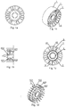
- Fig. 1 a-e presents various projections (a - longitudinal section, b - section through a chord, c - front view, d - isometric projection, e - perspective view) of the pulley described in the first embodiment, a version with two windows.
- V-belt each time this term is meant to be understood as any unending belt used in belt drives, which belt must have at least one element or groove with a trapezoidal cross-section or a shape similar to trapezoidal.
- the number of elements with a trapezoidal cross-section or elements with a shape similar to trapezoidal is not limited in advance, nor is the structure and construction of such a belt relevant, or the material of which it is made, or its geometric dimensions such as: length, width, pitch, the number of ribs, nor is it important whether the belt transmits the drive to a single receiving device, or if it is a serpentine belt driving numerous subsystems, nor is it significant how many pulleys, tensioning elements and vibration dampers this belt cooperates with. Also, it is of no relevance whether belt pulleys are driven by the carved part of the belt, or by its flat part.
- a pulley intended substantially for guiding or tensioning a V-belt in internal combustion engines of mechanical vehicles is made of a polyamide material with an admixture of fibreglass.
- a pulley consists of an outer ring 1 , from its outer side constituting a track for the V-belt, as well as an inner ring 2 , inside which a bearing 3 is seated. Between the rings there are support tongues 41 , 42 , in this embodiment arranged substantially radially with respect to the centre of the pulley. The width of tongues 41 and 42 at the inner ring 2 is smaller than the width of tongues at the outer ring.
- a support fill 5 Between certain tongues there is a support fill 5 , whose width is considerably smaller than the width of support tongues 4 .
- Some of the support tongues 41 are situated symmetrically and perpendicular to the central plane of the longitudinal section of the pulley and perpendicular to the surfaces of rings 1 and 2.
- Part of the tongues 42 is not symmetrical with respect to the central plane of the longitudinal section of the pulley.
- the asymmetrical tongue 42 is at one side at half of its width inclined away from the plane of the central longitudinal section of the pulley at the angle ⁇ ⁇ 1° - 60°>, which is presented in Fig. 6a-c.
- Fig. 6c presents the angle ⁇ with a low value, e.g. 1° or 5°, Fig.
- Asymmetrical tongues 42 are arranged with respect to each other in such a way that the uninclined part of one tongue 421 lies opposite the inclined part of the second tongue 422 .
- the support fill 5 is placed in the space between the symmetrical tongues 41 , as well as between the symmetrical tongues 41 and the asymmetrical tongues 42 . In the space between asymmetrical tongues 42 there is no support fill 5 .
- a space with no filling between tongues 4b forms a window 6 constituting an air blade.
- Windows 6 between the tongues 42 enable the flow of air between them.
- inclinations 421 and 422 of tongue surfaces result in capturing the air and directing it through the recess of the opening, and subsequently outside the pulley in a direction away from the area of lower temperature to the area of higher temperature.
- Such a shape of the tongues 42 creates air blades for the flow of air.
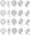
- Fig.1 a-e there can be two ( Fig.1 a-e ) or three ( Fig.2 a-e ) or four ( Fig.3 a-e ) or six ( Fig.4 a-e ) or eight windows ( Fig.5 a-e ) 6 , which are uniformly distributed in the circumferential space between rings 1 and 2 .
- a pulley in the configuration described above can rotate both ways, depending on the side in which the stream of air is supposed to flow through it. Therefore, it is possible to blow at an object to which it is attached, for example an engine body, or extract hot air from the engine body.
- the support tongues 41 and 42 of the pulley made of the same material as in embodiment 1 are inclined from the radius by the angle ⁇ ⁇ ⁇ 1° - 60°>.
- Fig. 12 a, b presents a version of the pulley where the angle ⁇ is 60° or 50°
- Fig. 13 a, b presents a version of the pulley where the angle ⁇ is 32°
- Fig. 14 a, b presents a version of the pulley where the angle ⁇ is 5° or 1°.
- the range of angles preferable due to air flow amounts to: ⁇ ⁇ ⁇ 5° - 50°>.
- the remaining arrangement of tongues is analogical to the first embodiment.
- the numbers of windows 6 specified in the first embodiment also apply to the present pulley with radially inclined tongues.
- the pulley is one-directional, i.e. It should rotate in the direction of inclination of the tongues.
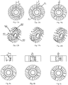
- the arrangement of tongues is the same as in embodiment 1 or 2, meaning that the pulley has tongues which are radially arranged or properly inclined away from the radius, although inside the polyamide casting there is metal reinforcement 7 ( Fig. 15 - Fig. 17 ).
- the reinforcement 7 is made of deep drawn sheet metal with thickness of approx. 6 mm. Openings 81 and 82 are made in the reinforcement 7.
- the reinforcement 7 has an inner ring 9 which metallically surrounds the housing of the bearing and corresponds to the inner ring 2 of the pulley, and an outer ring 10 which corresponds to the outer ring 1 of the pulley. Connecting elements 11 are placed between rings 9 and 10 of the reinforcement 7 .
- the reinforcement 7 has a substantially meshed construction, which is for example achieved by laser cutting.
- the meshed construction of the reinforcement 7 manifests itself in the existence of openings 81 in the connecting elements 11 , openings 82 in the outer ring 10 and in the through apertures 12 in the inner ring.
- the number of connecting elements 11 is proper for the number of windows 6 of the pulley.
- the manufacturing of a finished pulley involves applying the reinforcement 7 onto the bearing 3 and subsequently enclosing it in a casting mould, into which polyamide plastic is injected. Plastic passes through openings and apertures in the reinforcement, due to which the reinforcement is overpoured by it. After cooling down, the pulley constituting a hybrid of plastic and metal is removed from the mould.
- a polyamide pulley with inner reinforcement 7 is presented in Fig. 17 .
- the inner metal ring 9 surrounding the bearing in connection to the connecting elements 11 and the outer ring 10 causes increased dissipation of heat from the bearing.
- Metal is a considerably better heat conductor than plastic, due to which the dissipation of heat is more efficient.
- the reinforcement of the pulley also causes an increase in its resistance to mechanical load.
- the arrangement of tongues is the same as in embodiment 1 or 2, meaning that the pulley has tongues which are radially arranged or properly inclined away from the radius, although inside the polyamide casting there is metal reinforcement 13 ( Fig. 18 - Fig. 21 ).
- the reinforcement 13 is made of deep drawn sheet metal with thickness of approx. 6 mm.
- the reinforcement 13 has an inner ring 14 which metallically surrounds the housing of the bearing and corresponds to the inner ring 2 of the pulley, and an outer ring 15 which corresponds to the outer ring 1 of the pulley.
- Connecting elements 16 are placed between rings 14 and 15 of the reinforcement 13 .
- the number of connecting elements 16 is proper for the number of windows 6 of the pulley.
- the manufacturing of a finished pulley involves applying the reinforcement 13 onto the bearing 3 and subsequently enclosing it in a casting mould to which polymer plastic is injected, e.g. polyamide plastic. Plastic surrounds the reinforcement, due to which the reinforcement is overpoured by it. After cooling down, the pulley constituting a hybrid of plastic and metal is removed from the mould.
- a polyamide pulley with inner reinforcement 13 is presented in Figs. 20 and 21 .
- the inner metal ring 14 surrounding the bearing in connection to the connecting elements 16 and the outer ring 15 causes increased dissipation of heat from the bearing. Metal is a considerably better heat conductor than plastic, due to which the dissipation of heat is more efficient.
- the reinforcement of the pulley also causes an increase in its resistance to mechanical load.
- the method for dissipating heat from a bearing pulley is that the heat generated as a result of the rotational movement of the bearing 3 is dissipated via a metallic structure with a high heat transfer coefficient surrounding the housing of the bearing in the form of reinforcement 7, 13 , into the space between rings 1 and 2 of the pulley and into the surface of the outer circumference of the pulley, and it is additionally exposed to the flow of air between the inner 2 and outer ring 1 of the pulley caused by the rotational movement of the pulley and the properly shaped position of its tongues 42 .
- Other possible versions of shaping the tongues 42 and 41 are described in embodiment 1 and 2, while the construction of the metallic structure in the form of reinforcement has been described in embodiment 3a and 3b. Steel sheet metal for deep drawing DC01 has been used as reinforcement. It is also possible to use DC02, DC03 or DC04 sheet metal.
- each of the listed embodiments involving the device and the method can use another polymer plastic or polymer plastic with an admixture of reinforcing material.
- polyamide plastic polyamide PA6 may be used, pure or with an admixture of glass fibres GF or glass balls GB of up to 50%, e.g. PA6-30GF - a polyamide with a 30% admixture of glass fibres, PA6-GB40 - a polyamide with a 40% admixture of glass balls; the same applies to Polyamide PA66.
- Phenol-formaldehyde resins PF or melamine-phenol-formaldehyde resins MPF can also be used as polymer plastic.
- the thickness of the sheet metal of pulley reinforcement material can range from 0.1 to 5 mm.
- the reinforcement of the pulley can also be made of any solid material with a high heat transfer coefficient. For example, of materials such as steel, aluminium, copper, steel, nickel or alloys thereof, or alloys with other materials.
- Constructions of the pulley can also be used for rollers used with multi-ribbed belts, belts with a flat surface and chains. That is because the use of a belt or a chain or another transport medium depends on the shape of the pulley track.
- the invention is found useful in the automotive industry, as well as any other fields in which rotational movement is transferred from one element onto another by means of belts and/or chains.
Landscapes
- Engineering & Computer Science (AREA)
- General Engineering & Computer Science (AREA)
- Mechanical Engineering (AREA)
- Manufacturing & Machinery (AREA)
- Pulleys (AREA)
- Mounting Of Bearings Or Others (AREA)
- Rolling Contact Bearings (AREA)
Abstract
Description
- The object of the invention is the construction of a pulley intended for guiding or tensioning a V-belt, in particular in mechanical vehicles. The object of the invention is also a method for dissipating heat from the bearing of the pulley.
- Pulleys guiding or tensioning a V-belt in mechanical vehicles are usually made of metals, for example of steel or plastics, for example a polyamide with fibreglass. Plastic pulleys are produced by means of injection moulding. Metal pulleys are turned or drawn from sheet metal.
- The longevity of the pulley is largely dependent on the longevity of the bearing on which it is seated. The bearing is subject to the impact of mechanical forces and the resulting impact of temperature. Long-lasting operation under the conditions of high temperature generated as a result of the operation of the bearing, and also additionally originating from a heated up internal combustion engine block, impairs the longevity of the bearing. Metal is a good heat conductor, and therefore dissipation of temperature from the bearing is usually sufficient. In the case of plastic pulleys, the dissipation of heat from the bearing for a pulley operating under difficult temperature conditions is insufficient.
- In its known construction, the pulley consists of an outer ring, usually constituting a track for the V-belt, as well as an inner ring, inside which the bearing is seated. The space between the rings is usually filled, and in the case of plastic pulleys it is usually reinforced with ribbing consisting of convex tongues connecting both rings, which are arranged radially. Sometimes, in steel pulleys there are technical openings used for the access of a tool, usually a spanner, behind the pulley, or reducing its mass.
- Various bearing cooling methods are known from prior art. Cooling with air or liquid is used the most frequently. It is also known to surround the bearing with various kinds of radiators, aiming at the largest possible surface of a radiator.
- American patent description
US2017358326A1 discloses a computer hard drive assembly, the so-called e-block, which comprises a plurality of arms seated coaxially on bearings and driven by a VCM motor. Due to the fact that temperature in bearings increases during operation, the solution according to the patent comprises radiation elements which collect heat via the e-block and subsequently dissipate it into the surroundings. The radiation surface of these elements is larger than the surface of abutment with the e-block, via the use of a zigzagged or undulated surface. - Chinese description of utility model
CN202097039 (U ) discloses a device cooling the bearing of a decanter centrifuge. The device comprises a fan and an air guiding channel. Wherein the fan is attached on a centrifuge drum near the main bed of the bearing. The air driven by the fan blows at the bearing. - Japanese application description
JP2003293977A - German utility model
DE3025798 discloses a construction which enables the cooling of a bearing and a brake disc. A sphere or a roller bearing for supporting the wheels of a vehicle which are mounted on the outer track of the bearing with a brake drum or a brake disc has openings in the extension of the inner track, which act as a fan with a radial flow when the wheel is rotating. The flow of air generated this way is directed towards the bearing of the wheel and towards channels at the back of the brake disc, in order to cool down the bearing and the brake. The inner track of the ball bearing has openings in the flange carrying the brake disc and wheel, which act as a radial fan. The induced flow of air cools down the brake disc partially via the channels and partially via the outer track. - The object of the invention is the construction of a guiding or tensioning pulley made of plastic, which would allow better dissipation of heat from the bearing. The object of the invention is also the reduction of the amount of plastic used for its manufacturing. The object of the invention is the development of a method for more efficient dissipation of excess heat caused by the rotational movement of the bearing, heat accumulated from an internal combustion engine block and an increase in heat resulting from the too high tension of the belt guided by the pulley.
- During research it has been noticed that in spite of the rotational movement and the presence of tongues in a plastic pulley, it does not generate sufficient air flow to dissipate heat created as a result of friction in the bearing. Therefore, a modified construction of the pulley and a modified bearing cooling method have been proposed, achieved via this construction.
- The essence of the construction of the pulley according to the invention constitutes a pulley for tensioning or guiding a belt, substantially comprising a bearing on which the inner ring is seated, support tongues connecting the inner ring to the outer ring constituting a track for the pulley, and a support fill between the support tongues. The essence of the invention is that the pulley comprises at least two windows distributed uniformly in the circumferential space between rings. At their sides, the windows are delimited by the surface of tongues, which at one side substantially at half of their width are inclined away from the plane of the central longitudinal section of the pulley at the angle α∈ <1° - 60°> and are arranged with respect to each other in such a manner that the uninclined part of one tongue (421) lies opposite the inclined part of the second tongue (422).
- In another form, the tongues of the pulley are additionally inclined away from the radius of the pulley by the angle β ∈ <1° - 60°>, preferably β ∈ <5° - 50°> .
- In another particularly preferable form, the pulley is made of plastic and comprises metal reinforcement.
- Preferably, the metal reinforcement has an inner ring which comprises the housing of the bearing and corresponds to the inner ring of the pulley, and an outer ring which corresponds to the outer ring of the pulley, while connecting elements are placed between the rings of the reinforcement.
- In a preferable form, the discontinuous surface of the reinforcement manifests itself by the existence of openings in the connecting elements, openings in the outer ring and in the through apertures in the inner ring.
- Preferably, the plastic pulley constitutes polymer plastic or a composite of polymer plastic and a reinforcing material. Preferably, the polymer constitutes a polyamide or phenol-formaldehyde resins PF, or melamine-phenol-formaldehyde resins MPF.
- Preferably, the material of the reinforcement constitutes deep drawn sheet metal with thickness ranging from 0.1 to 5 mm, preferably ranging from 0.4 to 0.7 mm.
- Preferably, the width of the tongues at the inner ring is smaller than the width of the tongues at the outer ring.
- The essence of the method for dissipating heat from a bearing pulley according to the invention is that the heat generated as a result of the rotational movement of the bearing is dissipated via a metallic structure with a high heat transfer coefficient, surrounding the housing of the bearing in the form of reinforcement, into the space between the rings of the pulley and into the surface of the outer circumference of the pulley, and it is additionally exposed to the flow of air between the inner and outer ring of the pulley caused by the rotational movement of the pulley and the properly shaped position of its tongues.
- Due to the used intense flow of air from the surroundings with a lower temperature towards the surroundings with a higher temperature, the pulley according to the invention in an efficient manner dissipates excess heat from the bearing, which results in extending its longevity, and therefore the longevity of the entire pulley. Moreover, the pulley also acts as a fan with respect to the other elements of the arrangement; in particular, it can guide and therefore cool the drive element to which it is attached. The construction of the pulley causes considerable consumption of resource in the form of plastics. There is no plastic where the windows are. This has considerable influence on environmental protection. The use of metal reinforcements additionally increases the dissipation of heat, since this reinforcement acts as a radiator.
- The invention is presented in an embodiment in the drawing, where
Fig. 1 a-e presents various projections (a - longitudinal section, b - section through a chord, c - front view, d - isometric projection, e - perspective view) of the pulley described in the first embodiment, a version with two windows. -
Fig. 2 a-e presents respective projections of the pulley from the first embodiment, a version with three windows. -
Fig. 3 a-e presents respective projections of the pulley from the first embodiment, a version with four windows. -
Fig. 4 a-e presents respective projections of the pulley from the first embodiment, a version with six windows. -
Fig. 5 a-e presents respective projections of the pulley from the first embodiment, a version with eight windows. -
Fig. 6 a-c presents various versions of the angle α for the inclination of the tongues of the pulley away from the central plane of the longitudinal section of the pulley. -
Fig. 7 a-e presents various projections (a - longitudinal section, b - section through a chord, c - front view, d - isometric projection, e - perspective view) of the pulley described in the second embodiment, a version with two windows. -
Fig. 8 a-e presents respective projections of the pulley from the second embodiment, a version with three windows. -
Fig. 9 a-e presents respective projections of the pulley from the second embodiment, a version with four windows. -
Fig. 10 a-e presents respective projections of the pulley from the second embodiment, a version with six windows. -
Fig. 11 a-e presents respective projections of the pulley from the second embodiment, a version with eight windows. -
Fig. 12 a-b -Fig. 14 a-b presents various versions of the angle β for the inclination of the tongues of the pulley away from the radius of the pulley. -
Fig. 15 presents reinforcement of the pulley according to embodiment 3 a in an isometric projection, -
Fig. 16 presents the view of reinforcement according to embodiment 3 a from the front, -
Fig. 17 presents the view of a plastic pulley with inner reinforcement according to embodiment 3 a. -
Fig. 18 presents reinforcement of the pulley according to embodiment 3 b in an isometric projection, -
Fig. 19 presents the view of reinforcement according to embodiment 3 b from the front, -
Figs. 20, 21 present the view of a plastic pulley with inner reinforcement according to embodiment 3 b. - Whenever the present description mentions a V-belt, each time this term is meant to be understood as any unending belt used in belt drives, which belt must have at least one element or groove with a trapezoidal cross-section or a shape similar to trapezoidal. Also, the number of elements with a trapezoidal cross-section or elements with a shape similar to trapezoidal is not limited in advance, nor is the structure and construction of such a belt relevant, or the material of which it is made, or its geometric dimensions such as: length, width, pitch, the number of ribs, nor is it important whether the belt transmits the drive to a single receiving device, or if it is a serpentine belt driving numerous subsystems, nor is it significant how many pulleys, tensioning elements and vibration dampers this belt cooperates with. Also, it is of no relevance whether belt pulleys are driven by the carved part of the belt, or by its flat part.
- A pulley intended substantially for guiding or tensioning a V-belt in internal combustion engines of mechanical vehicles, presented in
Fig. 1 - Fig. 6 , is made of a polyamide material with an admixture of fibreglass. A pulley consists of anouter ring 1 , from its outer side constituting a track for the V-belt, as well as aninner ring 2 , inside which abearing 3 is seated. Between the rings there aresupport tongues tongues inner ring 2 is smaller than the width of tongues at the outer ring. Between certain tongues there is asupport fill 5 , whose width is considerably smaller than the width ofsupport tongues 4 . Some of thesupport tongues 41 are situated symmetrically and perpendicular to the central plane of the longitudinal section of the pulley and perpendicular to the surfaces ofrings tongues 42 is not symmetrical with respect to the central plane of the longitudinal section of the pulley. Theasymmetrical tongue 42 is at one side at half of its width inclined away from the plane of the central longitudinal section of the pulley at the angle α∈ <1° - 60°>, which is presented inFig. 6a-c. Fig. 6c presents the angle α with a low value, e.g. 1° or 5°,Fig. 6b presents the angle with a medium value, e.g. 20, 30°,Fig. 6a presents the angle with a high value, e.g. 60° or 45°. Preferable angle ranges in terms of the flow of air fall within a range of α∈ <10° - 45°>.Asymmetrical tongues 42 are arranged with respect to each other in such a way that the uninclined part of onetongue 421 lies opposite the inclined part of thesecond tongue 422 . The support fill 5 is placed in the space between thesymmetrical tongues 41 , as well as between thesymmetrical tongues 41 and theasymmetrical tongues 42 . In the space betweenasymmetrical tongues 42 there is nosupport fill 5 . A space with no filling between tongues 4b forms awindow 6 constituting an air blade. -
Windows 6 between thetongues 42 enable the flow of air between them. In addition,inclinations tongues 42 creates air blades for the flow of air. In typical pulleys according toembodiment 1 there can be two (Fig.1 a-e ) or three (Fig.2 a-e ) or four (Fig.3 a-e ) or six (Fig.4 a-e ) or eight windows (Fig.5 a-e ) 6 , which are uniformly distributed in the circumferential space betweenrings - In the second embodiment, the
support tongues embodiment 1 are inclined from the radius by the angle β ∈ <1° - 60°>.Fig. 12 a, b presents a version of the pulley where the angle β is 60° or 50°,Fig. 13 a, b presents a version of the pulley where the angle β is 32°,Fig. 14 a, b presents a version of the pulley where the angle β is 5° or 1°. The range of angles preferable due to air flow amounts to: β ∈ <5° - 50°>. The remaining arrangement of tongues is analogical to the first embodiment. The numbers ofwindows 6 specified in the first embodiment also apply to the present pulley with radially inclined tongues. (Fig 7a,b,c,d,e - Fig 11 a,b,c,d,e ) The pulley is one-directional, i.e. It should rotate in the direction of inclination of the tongues. - In embodiment 3a, the arrangement of tongues is the same as in
embodiment Fig. 15 - Fig. 17 ). Thereinforcement 7 is made of deep drawn sheet metal with thickness of approx. 6 mm.Openings reinforcement 7. Thereinforcement 7 has aninner ring 9 which metallically surrounds the housing of the bearing and corresponds to theinner ring 2 of the pulley, and anouter ring 10 which corresponds to theouter ring 1 of the pulley.Connecting elements 11 are placed betweenrings reinforcement 7 . Thereinforcement 7 has a substantially meshed construction, which is for example achieved by laser cutting. The meshed construction of thereinforcement 7 manifests itself in the existence ofopenings 81 in the connectingelements 11 ,openings 82 in theouter ring 10 and in the throughapertures 12 in the inner ring. The number of connectingelements 11 is proper for the number ofwindows 6 of the pulley. The manufacturing of a finished pulley involves applying thereinforcement 7 onto thebearing 3 and subsequently enclosing it in a casting mould, into which polyamide plastic is injected. Plastic passes through openings and apertures in the reinforcement, due to which the reinforcement is overpoured by it. After cooling down, the pulley constituting a hybrid of plastic and metal is removed from the mould. A polyamide pulley withinner reinforcement 7 is presented inFig. 17 . Theinner metal ring 9 surrounding the bearing in connection to the connectingelements 11 and theouter ring 10 causes increased dissipation of heat from the bearing. Metal is a considerably better heat conductor than plastic, due to which the dissipation of heat is more efficient. The reinforcement of the pulley also causes an increase in its resistance to mechanical load. - In embodiment 3b, the arrangement of tongues is the same as in
embodiment Fig. 18 - Fig. 21 ). Thereinforcement 13 is made of deep drawn sheet metal with thickness of approx. 6 mm. Thereinforcement 13 has aninner ring 14 which metallically surrounds the housing of the bearing and corresponds to theinner ring 2 of the pulley, and anouter ring 15 which corresponds to theouter ring 1 of the pulley.Connecting elements 16 are placed betweenrings reinforcement 13 . The number of connectingelements 16 is proper for the number ofwindows 6 of the pulley. The manufacturing of a finished pulley involves applying thereinforcement 13 onto thebearing 3 and subsequently enclosing it in a casting mould to which polymer plastic is injected, e.g. polyamide plastic. Plastic surrounds the reinforcement, due to which the reinforcement is overpoured by it. After cooling down, the pulley constituting a hybrid of plastic and metal is removed from the mould. A polyamide pulley withinner reinforcement 13 is presented inFigs. 20 and 21 . Theinner metal ring 14 surrounding the bearing in connection to the connectingelements 16 and theouter ring 15 causes increased dissipation of heat from the bearing. Metal is a considerably better heat conductor than plastic, due to which the dissipation of heat is more efficient. The reinforcement of the pulley also causes an increase in its resistance to mechanical load. - The method for dissipating heat from a bearing pulley is that the heat generated as a result of the rotational movement of the
bearing 3 is dissipated via a metallic structure with a high heat transfer coefficient surrounding the housing of the bearing in the form ofreinforcement rings outer ring 1 of the pulley caused by the rotational movement of the pulley and the properly shaped position of itstongues 42 . Other possible versions of shaping thetongues embodiment - Apart from polyamide plastic indicated in
embodiment 1, each of the listed embodiments involving the device and the method can use another polymer plastic or polymer plastic with an admixture of reinforcing material. In the case of polyamide plastic, polyamide PA6 may be used, pure or with an admixture of glass fibres GF or glass balls GB of up to 50%, e.g. PA6-30GF - a polyamide with a 30% admixture of glass fibres, PA6-GB40 - a polyamide with a 40% admixture of glass balls; the same applies to Polyamide PA66. Phenol-formaldehyde resins PF or melamine-phenol-formaldehyde resins MPF can also be used as polymer plastic. - The thickness of the sheet metal of pulley reinforcement material can range from 0.1 to 5 mm. The reinforcement of the pulley can also be made of any solid material with a high heat transfer coefficient. For example, of materials such as steel, aluminium, copper, steel, nickel or alloys thereof, or alloys with other materials.
- Constructions of the pulley can also be used for rollers used with multi-ribbed belts, belts with a flat surface and chains. That is because the use of a belt or a chain or another transport medium depends on the shape of the pulley track.
- The invention is found useful in the automotive industry, as well as any other fields in which rotational movement is transferred from one element onto another by means of belts and/or chains.
-
- 1. Outer ring
- 2. Inner ring
- 3. Bearing
- 4. Support tongue
- 41. symmetrical support tongue
- 42. asymmetrical support tongue
- 421, 422. inclination of the asymmetrical support tongue
- 5. Support fill
- 6. Window
- 7. Mesh reinforcement
- 8. Openings in reinforcement
- 81 openings in connecting
elements 11 - 82 openings in the
outer ring 10
- 81 openings in connecting
- 9. Inner ring of meshed reinforcement
- 10.Outer ring of meshed reinforcement
- 11.Connecting elements of meshed reinforcement
- α - angle of inclination from the plane of the central cross-section of the pulley
- β - angle of inclination from the radius of the pulley
- 12.Apertures
- 13.Solid reinforcement
- 14.Inner ring of solid reinforcement
- 15.Outer ring of solid reinforcement
- 16.Connecting elements of solid reinforcement
Claims (11)
- A V-belt pulley comprising substantially a bearing on which an inner ring is seated, support tongues connecting the inner ring to an outer ring constituting the track of the pulley, as well as a support fill between the support tongues, characterised in that it comprises at least two windows (6) uniformly distributed in the circumferential space between rings (1) and (2), where the windows (6) on their sides are delimited by the surface of tongues (42) which on one side substantially at half of their width are inclined away from the plane of the longitudinal section of the pulley by the angle α∈ <1° - 60°> and are arranged with respect to each other in such a manner that the uninclined part of one tongue (421) lies opposite the inclined part of the second tongue (422).
- The pulley according to claim 1, characterised in that the tongues are inclined away from the radius of the pulley by the angle β ∈ <1° - 60°>, preferably β ∈ <5° - 50°>.
- The pulley according to claim 1, characterised in that the angle α∈ <10° - 45°>.
- The pulley according to claim 1 or 2 or 3, characterised in that it is made of plastic and comprises metal reinforcement (7)
- The pulley according to claim 4, characterised in that the metal reinforcement (7) has an inner ring (9) which surrounds the housing of the bearing and corresponds to the inner ring (2) of the pulley, and an outer ring (10) which corresponds to the outer ring (1) of the pulley, while connecting elements (11) are placed between rings (9) and (10) of the reinforcement (7).
- The pulley according to claim 4 or 5, characterised in that the reinforcement (7) has a discontinuous surface manifesting itself in the existence of openings (81) in the connecting elements (11), openings (82) in the outer ring (10) and in the through apertures (12) in the inner ring.
- The pulley according to claim 1 or 2 or 3 or 4 or 5 or 6 characterised in that the plastic of the pulley constitutes polymer plastic or a composite of polymer plastic and a reinforcing material.
- The pulley according to claim 7, characterised in that polymer plastic constitutes a polyamide with an admixture of fibreglass, or phenol-formaldehyde resins PF or melamine-phenol-formaldehyde resins MPF.
- The pulley according to claim 4 or 5 or 6, characterised in that the material of reinforcement constitutes deep drawn sheet metal with thickness ranging from 0.1 to 5 mm.
- The pulley according to claim 1 or 2 or 3, characterised in that the width of the tongues at the inner ring is smaller than the width of the tongues at the outer ring.
- A method for dissipating heat from a bearing pulley characterised in that the heat generated as a result of the rotational movement of the bearing (3) is dissipated via a metallic structure with a high heat transfer coefficient, surrounding the housing of the bearing in the form of reinforcement (7), into the space between rings (1) and (2) of the pulley and into the surface of the outer circumference of the pulley, and it is additionally exposed to the flow of air between the inner (2) and outer ring (1) of the pulley caused by the rotational movement of the pulley and the properly shaped position of its tongues (42).
Applications Claiming Priority (1)
| Application Number | Priority Date | Filing Date | Title |
|---|---|---|---|
| PL424666A PL234507B1 (en) | 2018-02-23 | 2018-02-23 | V-belt roller and method to carry away heat from the roller bearing |
Publications (2)
| Publication Number | Publication Date |
|---|---|
| EP3537005A1 true EP3537005A1 (en) | 2019-09-11 |
| EP3537005B1 EP3537005B1 (en) | 2021-05-26 |
Family
ID=65903878
Family Applications (1)
| Application Number | Title | Priority Date | Filing Date |
|---|---|---|---|
| EP19158800.3A Active EP3537005B1 (en) | 2018-02-23 | 2019-02-22 | V-belt roller and method of removing heat from the roller bearing |
Country Status (3)
| Country | Link |
|---|---|
| EP (1) | EP3537005B1 (en) |
| PL (1) | PL234507B1 (en) |
| RU (1) | RU2734438C2 (en) |
Citations (3)
| Publication number | Priority date | Publication date | Assignee | Title |
|---|---|---|---|---|
| JP2001090811A (en) * | 1999-09-24 | 2001-04-03 | Nsk Ltd | Pulley |
| DE102008016303A1 (en) * | 2007-04-04 | 2008-10-09 | Aktiebolaget Skf | Tensioning roller device for internal combustion engine of motor vehicle, has fan with axial circular section and openings permitting radial removal of air flow, and wing with supporting section connected to circular section |
| JP2009121517A (en) * | 2007-11-12 | 2009-06-04 | Ntn Corp | Bearing with resin pulley |
Family Cites Families (3)
| Publication number | Priority date | Publication date | Assignee | Title |
|---|---|---|---|---|
| JP2007113655A (en) * | 2005-10-19 | 2007-05-10 | Calsonic Kansei Corp | Pulley, power transmission device, compressor, and cooling method |
| JP2011075000A (en) * | 2009-09-30 | 2011-04-14 | Nsk Ltd | Synthetic resin pulley |
| CN102912586B (en) * | 2012-10-26 | 2015-08-26 | 安徽工程大学 | A kind of detachable washing machine small belt wheel device |
-
2018
- 2018-02-23 PL PL424666A patent/PL234507B1/en unknown
-
2019
- 2019-02-19 RU RU2019104702A patent/RU2734438C2/en active
- 2019-02-22 EP EP19158800.3A patent/EP3537005B1/en active Active
Patent Citations (3)
| Publication number | Priority date | Publication date | Assignee | Title |
|---|---|---|---|---|
| JP2001090811A (en) * | 1999-09-24 | 2001-04-03 | Nsk Ltd | Pulley |
| DE102008016303A1 (en) * | 2007-04-04 | 2008-10-09 | Aktiebolaget Skf | Tensioning roller device for internal combustion engine of motor vehicle, has fan with axial circular section and openings permitting radial removal of air flow, and wing with supporting section connected to circular section |
| JP2009121517A (en) * | 2007-11-12 | 2009-06-04 | Ntn Corp | Bearing with resin pulley |
Also Published As
| Publication number | Publication date |
|---|---|
| RU2734438C2 (en) | 2020-10-16 |
| RU2019104702A3 (en) | 2020-08-19 |
| PL234507B1 (en) | 2020-03-31 |
| EP3537005B1 (en) | 2021-05-26 |
| RU2019104702A (en) | 2020-08-19 |
| PL424666A1 (en) | 2019-08-26 |
Similar Documents
| Publication | Publication Date | Title |
|---|---|---|
| KR101916748B1 (en) | High reliability and Lightweight Pre-Mounting Brake System for Commercial Vehicles | |
| US20160201690A1 (en) | Motor with heat dissipation structure capable of restraining temperature therein | |
| CN113202882B (en) | Heat dissipation type silicone oil clutch | |
| US20150323025A1 (en) | Brake disc | |
| US20100267505A1 (en) | V-shaped belt, belt-type transmission, and saddle-type vehicle | |
| TWI701396B (en) | Disc brakes for railway vehicles and disc brakes for railway vehicles | |
| EP3537005B1 (en) | V-belt roller and method of removing heat from the roller bearing | |
| TWI700206B (en) | Brake disc | |
| CN104500576A (en) | Rolling bearing retainer with radiating fins | |
| US9673690B2 (en) | Electromagnetic retarder rotor for a vehicle, retarder comprising such a rotor, and vehicle provided with such a retarder | |
| US20110118067A1 (en) | Drive with Belt | |
| US9748828B2 (en) | Overmolded flux ring | |
| KR101341621B1 (en) | Improvement of braking distance, and dust ventilator and radiation heating type disk brake | |
| KR102631378B1 (en) | Cooling unit for brake system | |
| JP2013104530A (en) | Braking device and tramway vehicle | |
| CN1890863A (en) | Advanced electromagnetic retarder annular rotor | |
| CN107492969B (en) | Electric motor | |
| JP2015129543A (en) | Torque fluctuation absorbing damper | |
| US20070166166A1 (en) | Cooling fan for radiator | |
| CN107269552B (en) | Insert for driving fan blade | |
| JP3919062B2 (en) | Hub unit for vehicles | |
| KR102774412B1 (en) | Vehicle hub space with heat dissipation function | |
| CN2813997Y (en) | Self-radiating braking drum | |
| JP2011185303A (en) | Transmission belt | |
| GB2343721A (en) | Friction disc for a clutch or disc brake |
Legal Events
| Date | Code | Title | Description |
|---|---|---|---|
| PUAI | Public reference made under article 153(3) epc to a published international application that has entered the european phase |
Free format text: ORIGINAL CODE: 0009012 |
|
| STAA | Information on the status of an ep patent application or granted ep patent |
Free format text: STATUS: THE APPLICATION HAS BEEN PUBLISHED |
|
| AK | Designated contracting states |
Kind code of ref document: A1 Designated state(s): AL AT BE BG CH CY CZ DE DK EE ES FI FR GB GR HR HU IE IS IT LI LT LU LV MC MK MT NL NO PL PT RO RS SE SI SK SM TR |
|
| AX | Request for extension of the european patent |
Extension state: BA ME |
|
| STAA | Information on the status of an ep patent application or granted ep patent |
Free format text: STATUS: REQUEST FOR EXAMINATION WAS MADE |
|
| 17P | Request for examination filed |
Effective date: 20200304 |
|
| RBV | Designated contracting states (corrected) |
Designated state(s): AL AT BE BG CH CY CZ DE DK EE ES FI FR GB GR HR HU IE IS IT LI LT LU LV MC MK MT NL NO PL PT RO RS SE SI SK SM TR |
|
| RIC1 | Information provided on ipc code assigned before grant |
Ipc: F16H 57/04 20100101ALN20200922BHEP Ipc: F16H 55/48 20060101ALI20200922BHEP Ipc: F16H 55/44 20060101ALI20200922BHEP Ipc: F16H 55/36 20060101AFI20200922BHEP |
|
| GRAP | Despatch of communication of intention to grant a patent |
Free format text: ORIGINAL CODE: EPIDOSNIGR1 |
|
| STAA | Information on the status of an ep patent application or granted ep patent |
Free format text: STATUS: GRANT OF PATENT IS INTENDED |
|
| RIC1 | Information provided on ipc code assigned before grant |
Ipc: F16H 55/44 20060101ALI20201012BHEP Ipc: F16H 57/04 20100101ALN20201012BHEP Ipc: F16H 55/48 20060101ALI20201012BHEP Ipc: F16H 55/36 20060101AFI20201012BHEP |
|
| RIC1 | Information provided on ipc code assigned before grant |
Ipc: F16H 55/48 20060101ALI20201021BHEP Ipc: F16H 55/36 20060101AFI20201021BHEP Ipc: F16H 55/44 20060101ALI20201021BHEP Ipc: F16H 57/04 20100101ALN20201021BHEP |
|
| INTG | Intention to grant announced |
Effective date: 20201111 |
|
| GRAS | Grant fee paid |
Free format text: ORIGINAL CODE: EPIDOSNIGR3 |
|
| GRAA | (expected) grant |
Free format text: ORIGINAL CODE: 0009210 |
|
| STAA | Information on the status of an ep patent application or granted ep patent |
Free format text: STATUS: THE PATENT HAS BEEN GRANTED |
|
| AK | Designated contracting states |
Kind code of ref document: B1 Designated state(s): AL AT BE BG CH CY CZ DE DK EE ES FI FR GB GR HR HU IE IS IT LI LT LU LV MC MK MT NL NO PL PT RO RS SE SI SK SM TR |
|
| REG | Reference to a national code |
Ref country code: GB Ref legal event code: FG4D |
|
| REG | Reference to a national code |
Ref country code: CH Ref legal event code: EP |
|
| REG | Reference to a national code |
Ref country code: DE Ref legal event code: R096 Ref document number: 602019004780 Country of ref document: DE |
|
| REG | Reference to a national code |
Ref country code: AT Ref legal event code: REF Ref document number: 1396542 Country of ref document: AT Kind code of ref document: T Effective date: 20210615 |
|
| REG | Reference to a national code |
Ref country code: IE Ref legal event code: FG4D |
|
| REG | Reference to a national code |
Ref country code: LT Ref legal event code: MG9D |
|
| REG | Reference to a national code |
Ref country code: AT Ref legal event code: MK05 Ref document number: 1396542 Country of ref document: AT Kind code of ref document: T Effective date: 20210526 |
|
| PG25 | Lapsed in a contracting state [announced via postgrant information from national office to epo] |
Ref country code: FI Free format text: LAPSE BECAUSE OF FAILURE TO SUBMIT A TRANSLATION OF THE DESCRIPTION OR TO PAY THE FEE WITHIN THE PRESCRIBED TIME-LIMIT Effective date: 20210526 Ref country code: HR Free format text: LAPSE BECAUSE OF FAILURE TO SUBMIT A TRANSLATION OF THE DESCRIPTION OR TO PAY THE FEE WITHIN THE PRESCRIBED TIME-LIMIT Effective date: 20210526 Ref country code: LT Free format text: LAPSE BECAUSE OF FAILURE TO SUBMIT A TRANSLATION OF THE DESCRIPTION OR TO PAY THE FEE WITHIN THE PRESCRIBED TIME-LIMIT Effective date: 20210526 Ref country code: BG Free format text: LAPSE BECAUSE OF FAILURE TO SUBMIT A TRANSLATION OF THE DESCRIPTION OR TO PAY THE FEE WITHIN THE PRESCRIBED TIME-LIMIT Effective date: 20210826 Ref country code: AT Free format text: LAPSE BECAUSE OF FAILURE TO SUBMIT A TRANSLATION OF THE DESCRIPTION OR TO PAY THE FEE WITHIN THE PRESCRIBED TIME-LIMIT Effective date: 20210526 |
|
| REG | Reference to a national code |
Ref country code: NL Ref legal event code: MP Effective date: 20210526 |
|
| PG25 | Lapsed in a contracting state [announced via postgrant information from national office to epo] |
Ref country code: GR Free format text: LAPSE BECAUSE OF FAILURE TO SUBMIT A TRANSLATION OF THE DESCRIPTION OR TO PAY THE FEE WITHIN THE PRESCRIBED TIME-LIMIT Effective date: 20210827 Ref country code: IS Free format text: LAPSE BECAUSE OF FAILURE TO SUBMIT A TRANSLATION OF THE DESCRIPTION OR TO PAY THE FEE WITHIN THE PRESCRIBED TIME-LIMIT Effective date: 20210926 Ref country code: LV Free format text: LAPSE BECAUSE OF FAILURE TO SUBMIT A TRANSLATION OF THE DESCRIPTION OR TO PAY THE FEE WITHIN THE PRESCRIBED TIME-LIMIT Effective date: 20210526 Ref country code: NO Free format text: LAPSE BECAUSE OF FAILURE TO SUBMIT A TRANSLATION OF THE DESCRIPTION OR TO PAY THE FEE WITHIN THE PRESCRIBED TIME-LIMIT Effective date: 20210826 Ref country code: PL Free format text: LAPSE BECAUSE OF FAILURE TO SUBMIT A TRANSLATION OF THE DESCRIPTION OR TO PAY THE FEE WITHIN THE PRESCRIBED TIME-LIMIT Effective date: 20210526 Ref country code: RS Free format text: LAPSE BECAUSE OF FAILURE TO SUBMIT A TRANSLATION OF THE DESCRIPTION OR TO PAY THE FEE WITHIN THE PRESCRIBED TIME-LIMIT Effective date: 20210526 Ref country code: PT Free format text: LAPSE BECAUSE OF FAILURE TO SUBMIT A TRANSLATION OF THE DESCRIPTION OR TO PAY THE FEE WITHIN THE PRESCRIBED TIME-LIMIT Effective date: 20210927 Ref country code: SE Free format text: LAPSE BECAUSE OF FAILURE TO SUBMIT A TRANSLATION OF THE DESCRIPTION OR TO PAY THE FEE WITHIN THE PRESCRIBED TIME-LIMIT Effective date: 20210526 |
|
| PG25 | Lapsed in a contracting state [announced via postgrant information from national office to epo] |
Ref country code: NL Free format text: LAPSE BECAUSE OF FAILURE TO SUBMIT A TRANSLATION OF THE DESCRIPTION OR TO PAY THE FEE WITHIN THE PRESCRIBED TIME-LIMIT Effective date: 20210526 |
|
| PG25 | Lapsed in a contracting state [announced via postgrant information from national office to epo] |
Ref country code: ES Free format text: LAPSE BECAUSE OF FAILURE TO SUBMIT A TRANSLATION OF THE DESCRIPTION OR TO PAY THE FEE WITHIN THE PRESCRIBED TIME-LIMIT Effective date: 20210526 Ref country code: EE Free format text: LAPSE BECAUSE OF FAILURE TO SUBMIT A TRANSLATION OF THE DESCRIPTION OR TO PAY THE FEE WITHIN THE PRESCRIBED TIME-LIMIT Effective date: 20210526 Ref country code: SK Free format text: LAPSE BECAUSE OF FAILURE TO SUBMIT A TRANSLATION OF THE DESCRIPTION OR TO PAY THE FEE WITHIN THE PRESCRIBED TIME-LIMIT Effective date: 20210526 Ref country code: CZ Free format text: LAPSE BECAUSE OF FAILURE TO SUBMIT A TRANSLATION OF THE DESCRIPTION OR TO PAY THE FEE WITHIN THE PRESCRIBED TIME-LIMIT Effective date: 20210526 Ref country code: DK Free format text: LAPSE BECAUSE OF FAILURE TO SUBMIT A TRANSLATION OF THE DESCRIPTION OR TO PAY THE FEE WITHIN THE PRESCRIBED TIME-LIMIT Effective date: 20210526 Ref country code: SM Free format text: LAPSE BECAUSE OF FAILURE TO SUBMIT A TRANSLATION OF THE DESCRIPTION OR TO PAY THE FEE WITHIN THE PRESCRIBED TIME-LIMIT Effective date: 20210526 Ref country code: RO Free format text: LAPSE BECAUSE OF FAILURE TO SUBMIT A TRANSLATION OF THE DESCRIPTION OR TO PAY THE FEE WITHIN THE PRESCRIBED TIME-LIMIT Effective date: 20210526 |
|
| REG | Reference to a national code |
Ref country code: DE Ref legal event code: R097 Ref document number: 602019004780 Country of ref document: DE |
|
| PLBE | No opposition filed within time limit |
Free format text: ORIGINAL CODE: 0009261 |
|
| STAA | Information on the status of an ep patent application or granted ep patent |
Free format text: STATUS: NO OPPOSITION FILED WITHIN TIME LIMIT |
|
| 26N | No opposition filed |
Effective date: 20220301 |
|
| PG25 | Lapsed in a contracting state [announced via postgrant information from national office to epo] |
Ref country code: IS Free format text: LAPSE BECAUSE OF FAILURE TO SUBMIT A TRANSLATION OF THE DESCRIPTION OR TO PAY THE FEE WITHIN THE PRESCRIBED TIME-LIMIT Effective date: 20210926 Ref country code: AL Free format text: LAPSE BECAUSE OF FAILURE TO SUBMIT A TRANSLATION OF THE DESCRIPTION OR TO PAY THE FEE WITHIN THE PRESCRIBED TIME-LIMIT Effective date: 20210526 |
|
| PG25 | Lapsed in a contracting state [announced via postgrant information from national office to epo] |
Ref country code: IT Free format text: LAPSE BECAUSE OF FAILURE TO SUBMIT A TRANSLATION OF THE DESCRIPTION OR TO PAY THE FEE WITHIN THE PRESCRIBED TIME-LIMIT Effective date: 20210526 |
|
| PG25 | Lapsed in a contracting state [announced via postgrant information from national office to epo] |
Ref country code: MC Free format text: LAPSE BECAUSE OF FAILURE TO SUBMIT A TRANSLATION OF THE DESCRIPTION OR TO PAY THE FEE WITHIN THE PRESCRIBED TIME-LIMIT Effective date: 20210526 |
|
| REG | Reference to a national code |
Ref country code: CH Ref legal event code: PL |
|
| REG | Reference to a national code |
Ref country code: BE Ref legal event code: MM Effective date: 20220228 |
|
| PG25 | Lapsed in a contracting state [announced via postgrant information from national office to epo] |
Ref country code: LU Free format text: LAPSE BECAUSE OF NON-PAYMENT OF DUE FEES Effective date: 20220222 |
|
| PG25 | Lapsed in a contracting state [announced via postgrant information from national office to epo] |
Ref country code: FR Free format text: LAPSE BECAUSE OF NON-PAYMENT OF DUE FEES Effective date: 20220228 |
|
| PG25 | Lapsed in a contracting state [announced via postgrant information from national office to epo] |
Ref country code: LI Free format text: LAPSE BECAUSE OF NON-PAYMENT OF DUE FEES Effective date: 20220228 Ref country code: IE Free format text: LAPSE BECAUSE OF NON-PAYMENT OF DUE FEES Effective date: 20220222 Ref country code: CH Free format text: LAPSE BECAUSE OF NON-PAYMENT OF DUE FEES Effective date: 20220228 |
|
| PG25 | Lapsed in a contracting state [announced via postgrant information from national office to epo] |
Ref country code: BE Free format text: LAPSE BECAUSE OF NON-PAYMENT OF DUE FEES Effective date: 20220228 |
|
| GBPC | Gb: european patent ceased through non-payment of renewal fee |
Effective date: 20230222 |
|
| PG25 | Lapsed in a contracting state [announced via postgrant information from national office to epo] |
Ref country code: GB Free format text: LAPSE BECAUSE OF NON-PAYMENT OF DUE FEES Effective date: 20230222 |
|
| PG25 | Lapsed in a contracting state [announced via postgrant information from national office to epo] |
Ref country code: GB Free format text: LAPSE BECAUSE OF NON-PAYMENT OF DUE FEES Effective date: 20230222 |
|
| PG25 | Lapsed in a contracting state [announced via postgrant information from national office to epo] |
Ref country code: MK Free format text: LAPSE BECAUSE OF FAILURE TO SUBMIT A TRANSLATION OF THE DESCRIPTION OR TO PAY THE FEE WITHIN THE PRESCRIBED TIME-LIMIT Effective date: 20210526 Ref country code: CY Free format text: LAPSE BECAUSE OF FAILURE TO SUBMIT A TRANSLATION OF THE DESCRIPTION OR TO PAY THE FEE WITHIN THE PRESCRIBED TIME-LIMIT Effective date: 20210526 |
|
| PG25 | Lapsed in a contracting state [announced via postgrant information from national office to epo] |
Ref country code: HU Free format text: LAPSE BECAUSE OF FAILURE TO SUBMIT A TRANSLATION OF THE DESCRIPTION OR TO PAY THE FEE WITHIN THE PRESCRIBED TIME-LIMIT; INVALID AB INITIO Effective date: 20190222 |
|
| PG25 | Lapsed in a contracting state [announced via postgrant information from national office to epo] |
Ref country code: MT Free format text: LAPSE BECAUSE OF FAILURE TO SUBMIT A TRANSLATION OF THE DESCRIPTION OR TO PAY THE FEE WITHIN THE PRESCRIBED TIME-LIMIT Effective date: 20210526 |
|
| PG25 | Lapsed in a contracting state [announced via postgrant information from national office to epo] |
Ref country code: TR Free format text: LAPSE BECAUSE OF FAILURE TO SUBMIT A TRANSLATION OF THE DESCRIPTION OR TO PAY THE FEE WITHIN THE PRESCRIBED TIME-LIMIT Effective date: 20210526 |
|
| PGFP | Annual fee paid to national office [announced via postgrant information from national office to epo] |
Ref country code: DE Payment date: 20260210 Year of fee payment: 8 |