EP3536979A1 - Servovalve with adjustable air gaps - Google Patents
Servovalve with adjustable air gaps Download PDFInfo
- Publication number
- EP3536979A1 EP3536979A1 EP18461529.2A EP18461529A EP3536979A1 EP 3536979 A1 EP3536979 A1 EP 3536979A1 EP 18461529 A EP18461529 A EP 18461529A EP 3536979 A1 EP3536979 A1 EP 3536979A1
- Authority
- EP
- European Patent Office
- Prior art keywords
- pole piece
- attachment means
- opening
- armature
- torque motor
- Prior art date
- Legal status (The legal status is an assumption and is not a legal conclusion. Google has not performed a legal analysis and makes no representation as to the accuracy of the status listed.)
- Granted
Links
- 230000004044 response Effects 0.000 claims abstract description 5
- 238000000034 method Methods 0.000 claims description 24
- 230000008878 coupling Effects 0.000 claims description 2
- 238000010168 coupling process Methods 0.000 claims description 2
- 238000005859 coupling reaction Methods 0.000 claims description 2
- 238000009760 electrical discharge machining Methods 0.000 description 2
- 230000004907 flux Effects 0.000 description 2
- 230000008569 process Effects 0.000 description 2
- 230000000694 effects Effects 0.000 description 1
- 239000003292 glue Substances 0.000 description 1
- 230000004048 modification Effects 0.000 description 1
- 238000012986 modification Methods 0.000 description 1
- 239000007787 solid Substances 0.000 description 1
Images


Classifications
-
- F—MECHANICAL ENGINEERING; LIGHTING; HEATING; WEAPONS; BLASTING
- F15—FLUID-PRESSURE ACTUATORS; HYDRAULICS OR PNEUMATICS IN GENERAL
- F15B—SYSTEMS ACTING BY MEANS OF FLUIDS IN GENERAL; FLUID-PRESSURE ACTUATORS, e.g. SERVOMOTORS; DETAILS OF FLUID-PRESSURE SYSTEMS, NOT OTHERWISE PROVIDED FOR
- F15B13/00—Details of servomotor systems ; Valves for servomotor systems
- F15B13/02—Fluid distribution or supply devices characterised by their adaptation to the control of servomotors
- F15B13/04—Fluid distribution or supply devices characterised by their adaptation to the control of servomotors for use with a single servomotor
- F15B13/042—Fluid distribution or supply devices characterised by their adaptation to the control of servomotors for use with a single servomotor operated by fluid pressure
- F15B13/043—Fluid distribution or supply devices characterised by their adaptation to the control of servomotors for use with a single servomotor operated by fluid pressure with electrically-controlled pilot valves
- F15B13/0438—Fluid distribution or supply devices characterised by their adaptation to the control of servomotors for use with a single servomotor operated by fluid pressure with electrically-controlled pilot valves the pilot valves being of the nozzle-flapper type
-
- H—ELECTRICITY
- H02—GENERATION; CONVERSION OR DISTRIBUTION OF ELECTRIC POWER
- H02K—DYNAMO-ELECTRIC MACHINES
- H02K26/00—Machines adapted to function as torque motors, i.e. to exert a torque when stalled
-
- H—ELECTRICITY
- H01—ELECTRIC ELEMENTS
- H01F—MAGNETS; INDUCTANCES; TRANSFORMERS; SELECTION OF MATERIALS FOR THEIR MAGNETIC PROPERTIES
- H01F7/00—Magnets
- H01F7/06—Electromagnets; Actuators including electromagnets
- H01F7/08—Electromagnets; Actuators including electromagnets with armatures
- H01F7/14—Pivoting armatures
- H01F7/145—Rotary electromagnets with variable gap
-
- H—ELECTRICITY
- H02—GENERATION; CONVERSION OR DISTRIBUTION OF ELECTRIC POWER
- H02K—DYNAMO-ELECTRIC MACHINES
- H02K1/00—Details of the magnetic circuit
- H02K1/06—Details of the magnetic circuit characterised by the shape, form or construction
- H02K1/08—Salient poles
-
- H—ELECTRICITY
- H02—GENERATION; CONVERSION OR DISTRIBUTION OF ELECTRIC POWER
- H02K—DYNAMO-ELECTRIC MACHINES
- H02K15/00—Processes or apparatus specially adapted for manufacturing, assembling, maintaining or repairing of dynamo-electric machines
- H02K15/06—Embedding prefabricated windings in the machines
- H02K15/061—Air-gap windings
-
- H—ELECTRICITY
- H02—GENERATION; CONVERSION OR DISTRIBUTION OF ELECTRIC POWER
- H02K—DYNAMO-ELECTRIC MACHINES
- H02K15/00—Processes or apparatus specially adapted for manufacturing, assembling, maintaining or repairing of dynamo-electric machines
- H02K15/06—Embedding prefabricated windings in the machines
- H02K15/062—Windings in slots; Salient pole windings
-
- H—ELECTRICITY
- H02—GENERATION; CONVERSION OR DISTRIBUTION OF ELECTRIC POWER
- H02K—DYNAMO-ELECTRIC MACHINES
- H02K2201/00—Specific aspects not provided for in the other groups of this subclass relating to the magnetic circuits
- H02K2201/03—Machines characterised by aspects of the air-gap between rotor and stator
-
- H—ELECTRICITY
- H02—GENERATION; CONVERSION OR DISTRIBUTION OF ELECTRIC POWER
- H02K—DYNAMO-ELECTRIC MACHINES
- H02K2213/00—Specific aspects, not otherwise provided for and not covered by codes H02K2201/00 - H02K2211/00
- H02K2213/09—Machines characterised by the presence of elements which are subject to variation, e.g. adjustable bearings, reconfigurable windings, variable pitch ventilators
Definitions
- the sum of the opposite air gaps (16a+16d and 16b+16c) determines characteristic stroke of the armature versus current applied to the coils.
Landscapes
- Physics & Mathematics (AREA)
- Engineering & Computer Science (AREA)
- Electromagnetism (AREA)
- Power Engineering (AREA)
- Fluid Mechanics (AREA)
- Mechanical Engineering (AREA)
- General Engineering & Computer Science (AREA)
- Iron Core Of Rotating Electric Machines (AREA)
Abstract
Description
- Flow control in a flapper-nozzle servo valve relies on the movement of a flapper between two nozzles. The movement is as a result of the rotation of an armature and the rotation of the armature is provided by a torque motor, which is controlled by current applied to a coil. A proper characteristic of the movement (stroke of a flapper) versus the current in a coil is mandatory.
- One of the main parameters which has an influence on the performance of a torque motor is the value of the air gap between the pole piece and the armature. Currently, in some applications, the pole piece is one solid and the air gap is provided by Electrical Discharge Machining (EDM). This process is very time-consuming and expensive. The risk of fall out debris is high and the operator of the EDM process must be highly skilled.
- In other applications, the position of the armature between pole pieces is set by adjusting the position of the pole pieces and/or adjusting of the position of the armature (for example, by using a null bias spring).
- In one example, there is provided a torque motor for a servovalve, the torque motor including an armature and a first pole piece. The first pole piece has a first portion and a second portion that is selectively moveable relative to the first portion such that a size of an air gap formed between the second portion and the armature is adjusted in response to the movement of the second portion relative to the first portion.
- Preferably, the torque motor may further comprise a second pole piece and the armature may be disposed between the first pole piece and the second pole piece. The first pole piece may further comprise a first pole piece section with a ring shape extending in a plane, and the first portion may extend perpendicularly away from the first pole piece section to an angled disposed at an angle relative to the plane.
- Further, the second portion can have a first surface disposed at the same angle as the angled surface and a second surface substantially parallel to the plane. The first surface of the second portion may be releasably coupled to the angled surface.
- Preferably, a first surface of the armature and the second surface of the second portion between which the
air gap - Further, movement of the second portion relative to the first portion may be in a direction parallel to the first surface.
- Preferably, the angled surfaces may be disposed at an angle of between 5° and 25° to the plane.
- Further, the torque motor may further comprise attachment means configured to attach the second portion to the first portion, and preferably may further comprise retaining means secured onto the attachment means to secure the second portion to the first pole piece section and even more preferably the attachment means may be a screw and the retaining means can be a nut.
- Further, the first pole piece section and the first portion may further comprise an opening and the second portion may further comprise an opening, and wherein the attachment means can be provided through the opening in the first pole piece section and the first portion, and the opening in the second portion. Preferably, the opening in the first pole piece section may be a slot to provide an area for movement of the attachment means, and the opening in the second portion may have the same diameter as the attachment means, such that the attachment means may be flush with the opening of the second portion.
- In another example, a method of adjusting an air gap in a torque motor is provided. The method comprises providing an armature and providing a first pole piece. The first pole piece has a first portion and a second portion. The method further comprises selectively moving the second portion relative to the first portion such that a size of an air gap formed between the second portion and the armature is adjusted in response to the movement of the second portion relative to the first portion.
- Preferably, the method may further comprise providing a second pole piece, and disposing the armature between the first pole piece and the second pole piece. The first pole piece may further comprise a first pole piece section with a ring shape extending in a plane, and the first portion may extend perpendicularly away from the first pole piece section to an angled surface that may be disposed at an angle relative to the plane. The second portion may have a first surface disposed at the same angle as the angled surface and a second surface that may be substantially parallel to the plane. Further, the method may also include coupling the first surface of the second portion to the angled surface.
- Further, a first surface of the armature and the second surface of the second portion between which the air gap may be defined can remain substantially parallel throughout a range of relative movement between the first portion and the second portion.
- The method may also comprise moving the second portion relative to the first portion in a direction parallel to the first surface. The angled surfaces may be disposed at an angle of between 5° and 25° to the plane.
- Preferably, the method may also further comprise providing attachment means to attach the second portion to the first portion and preferably, the method may also further comprise tightening a retaining means onto the attachment means for securing the second portion to the first portion.
- Further, the first pole piece section and first portion may further comprise an opening and the second portion may further comprise an opening. The method may further comprise providing the attachment means through the opening in the first pole piece section and the first portion, and the opening in the second portion. Preferably, the opening in the first pole piece section and first section can be a slot providing an area for movement of the attachment means, and the opening in the second portion may have the same diameter as the attachment means such that the attachment means may be flush with the opening of the second portion.
- Further, the method may also comprise loosening the attachment means and the retaining means, moving the second portion in a direction parallel to the plane, and therefore moving the attachment means within the opening to result in an adjustment of the air gap. Further, the method may also comprise tightening the attachment means and the retaining means, thereby securing the second portion in position in relation to the first portion.
-
-
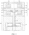
Figure 1 shows a side cross sectional view of a known servovalve. -
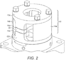
Figure 2 shows a perspective view of a known torque motor. -
Figure 3 shows a perspective view of an example of a new type of torque motor as described herein. -
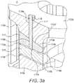
Figure 3a shows a detailed cross sectional view of the second portion seen in section A offigure 3 . -
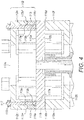
Figure 4 shows a side view cross section of a torque motor as described herein, depicting air gaps between the pole pieces and the armature. -
Figures 5a to 5c show three potential magnitudes of an adjustable air gap of the torque motor described herein. -
Figure 1 depicts a side cross sectional view of a known servovalve comprisingtorque motor 10 and anozzle 20. Thetorque motor 10 comprises first and secondmagnetic coils second pole pieces armature 15 located between the first andsecond pole pieces flapper nozzle servovalve 20 comprisesflapper 21 coupled at one end to thearmature 15, andnozzle 22. - First and
second pole pieces first portions second portions figure 1 . Upon assembly, the first andsecond pole pieces armature 15 is positioned between the perpendicularly extending portions of the first and second pole pieces andair gaps 16a-16d are provided between the armature and the first andsecond portion 12c-12f of each pole piece. - First and second
magnetic coils armature 15. When a current is applied to thecoils armature 15 to be attracted to thepole pieces armature 15, and therefore theflapper 21. - The magnitude of
air gaps 16a-16d has a profound effect on the performance of thetorque motor 10, and therefore proper calibration of theseair gaps 16a-16d is crucial. A small mismatch between the magnitudes of theair gaps 16a-16d can cause the null position of thearmature 15 to not be centred. In such a case, a "null current" must be applied in order to restore the position of the armature to the centred position. Whilst in some cases this is undesirable, in other cases it may be so desired to providemismatched air gaps 16a-16d, and therefore provide a non-zero null position of thearmature 15. A sum of the opposite air gaps (e.g. 16a+16d and 16b+16c) determines characteristic stroke of the armature versus current applied to the coils. -
Figure 2 depicts a perspective view of a knowntorque motor 10. The same features oftorque motor 10 are indicated with the same reference numerals asfigure 1 . As can be seen infigure 2 ,torque motor 10 is also provided with first and secondpermanent magnets second pole pieces -
Figure 3 depicts a perspective view of an example of a servo valvetorque motor apparatus 110. Thetorque motor 110 comprises first and second magnetic coils (not shown), first andsecond pole pieces permanent magnets armature 115, attachment means 117 and retaining means 118. - First
pole piece section 112a has a "C-shaped" cross section, with a ring shape extending in a first plane, and further comprisesfirst portions figure 4 . Thefirst portions pole piece section 112a extend from the first plane toangled surfaces 112c' and 112e', which are disposed at an angle to the firstpole piece section 112a. Preferably, theangled surfaces 112c' and 112e' are angled between 5° and 25° to the first plane. - There are also provided
second portions 113 that are moveable relative to thefirst portions corresponding air gap second portion 113 and thearmature 115. Thesecond portions 113 havefirst surfaces 113a that may have the same angle to a correspondingangled surface 112c', 112e' of the firstpole piece section 112a. Thesecond portions 113 extend in a direction perpendicular to the first plane of the firstpole piece section 112a from thefirst surface 113a, to asecond surface 113b substantially parallel to the first plane of the firstpole piece section 112a and, therefore, parallel to thearmature 115. Firstpole piece section 112a,first portions second portions 113 together formfirst pole piece 112. - The
second portions 113 may have a trapezoidal cross section, but other shapes are envisaged. - Upon assembly, the
first pole piece 112 is arranged so that thesecond surface 113b of thesecond portions 113 extends towards afirst surface 115a of thearmature 115. -
Second pole piece 112b has a "C-shaped" cross section, with a ring shaped section extending in a second plane, and further comprisesfirst portions 112d andportion 112f extending perpendicularly away from the second plane, as seen infigure 4 . - The
first portions second pole piece 112b extend from thesecond pole piece 112b in the same direction. Upon assembly, thesecond pole piece 112b is arranged so that the perpendicularly extendingfirst portions second surface 115b of thearmature 115. - The
armature 115 is therefore positioned between thesecond surface 113b of thesecond portions 113 and the perpendicularly extendingfirst portions second pole piece 112b. - First and second
permanent magnets pole piece section 112a andsecond pole piece 112b. -
Figure 3a depicts a cross section of subsection A offigure 3 , and shows in more detail one of thesecond portions 113. - Attachment means 117 extends through an
opening 119a in the firstpole piece section 112a and thefirst portion 112c and anopening 119b in thesecond portion 113, thereby attachingsecond portion 113 to the firstpole piece section 112a andfirst portion 112c. Retaining means 118 may be secured onto the attachment means 117 to secure thesecond portion 113. -
Opening 119a may be a slot providing an area for movement of the attachment means 117, andopening 119b may have the same diameter as attachment means 117 such that the attachment means 117 is flush with theopening 119b, thereby allowing for lateral movement of the attachment means 117 and thesecond portion 113. Due to the angle of theangled surfaces 112c' and 112e', and the corresponding angle of thefirst surface 113a of thesecond portion 113, the movement of thesecond portion 113 in a direction parallel to the first plane (and a corresponding loosening or tightening of the attachment and retaining means 117, 118) will also result in a movement of thesecond portion 113 in a direction perpendicular to the first plane, thereby varying the magnitude of theair gap 116a. Theair gap 116a between thefirst pole piece 112 and thearmature 115 may therefore be quickly and reversibly adjusted. - Attachment means 117 may be non-magnetic, and may be provided with a
hard stop 117a to prevent latching of the armature to thesecond portion 113. Attachment means 117 may be a threaded screw, with the end of the screw providing ahard stop 117a for thearmature 115. - Retaining means 118 may be a locking nut, and further may be provided with an anti-vibration washer. Retaining means 118 may be secured with glue to prevent unwanted movement during operation.
-
Figure 4 depicts a cross section of thetorque motor 110.Air gap 116a is formed between afirst surface 115a of thearmature 115 and asecond surface 113b of thesecond portion 113 associated with thefirst portion 112c of the firstpole piece section 112a. -
Air gap 116b is provided between asecond surface 115b of thearmature 115 substantially opposite to the first surface, and a first surface of thesecond pole piece 112b. -
Air gap 116c is formed between thefirst surface 115a of thearmature 115 and thesecond surface 113b of thesecond portion 113 associated with thefirst portion 112e of the firstpole piece section 112a. -
Air gap 116d is provided between asecond surface 115b of thearmature 115 substantially opposite to the first surface, and a first surface of thesecond pole piece 112b. -
Figures 5a-5c show three positions of thesecond portion 113, and therefore three potential magnitudes ofair gap 116a. Theportion 113 may be moved laterally to either increase or decrease the value ofair gap 116a. - As can be seen in
Figure 5a , the user has securedsecond portion 113 in the left-most position. This may be achieved by manually loosening the attachment means 117 and retaining means 118, and then moving thesecond portion 113 and therefore the attachment means 117 within the slot (not shown) to the left-most position possible. Once thesecond portion 113 is in the desired location (in this case, in its left-most position), the attachment means 117 and 118 may be tightened so as to secure thesecond portion 113 in position in relation to the firstpole piece section 112a. Due to the angle of thefirst surface 113a of thesecond portion 113, and the corresponding angle of theangled surface 112c' of the firstpole piece section 112a, by providing thesecond portion 113 at its left-most position, theair gap 116a may be at a maximal value. - As shown in
Figure 5b , the user has secured thesecond portion 113 in a nominal position, reducing the magnitude of theair gap 116a from the value provided by the left-most position of thesecond portion 113 seen inFigure 5a . This may be achieved by manually loosening the attachment means 117 and retaining means 118, and then moving thesecond portion 113 and therefore the attachment means 117 within the slot (not shown) to a desired position, which may be determined by a desired value of theair gap 116a. Once thesecond portion 113 is in the desired location, the attachment means 117 and 118 may be tightened so as to secure thesecond portion 113 in position in relation to firstpole piece section 112a. Due to the angle of thefirst surface 113a of thesecond portion 113, and the corresponding angle of theangled surface 112c' of the firstpole piece section 112a, by providing thesecond portion 113 further towards the centre when compared to the position seen inFigure 5a , the magnitude ofair gap 116a may be reduced when compared to the magnitude seen inFigure 5a . -
Figure 5c shows a minimal value of theair gap 116a. The user has secured thesecond portion 113 in the right-most position, reducing the magnitude of theair gap 116a to the minimum possible value. This may be achieved by manually loosening the attachment means 117 and retaining means 118, and then moving thesecond portion 113 and therefore the attachment means 117 within the slot (not shown) to the right-most position. Once thesecond portion 113 is in the desired location, the attachment means 117 and 118 may be tightened so as to secure thesecond portion 113 in position in relation to firstpole piece section 112a. Due to the angle of thefirst surface 113a of thesecond portion 113, and the corresponding angle of theangled surface 112c' of the firstpole piece section 112a, by providing thesecond portion 113 at its right-most position, the magnitude ofair gap 116a may be reduced when compared to the magnitude seen inFigures 5a and 5b . As can be seen inFigure 5c , ahard stop 117a provided with attachment means 117 may provide a physical stop to prevent latching of thearmature 115 to thesecond portion 113. - The
first surface 115a of thearmature 115 and thesecond surface 113b of thesecond portion 113 may remain substantially parallel throughout movement of thesecond portions 113. The movement of thesecond portions 113 relative to the respectivefirst portion first surface 113a of thesecond portion 113. - Although not seen in
figures 5a-5c , a correspondingsecond portion 113 associated with thefirst portion 112e of the firstpole piece section 112a can be moved accordingly to adjustair gap 116c. - As outlined above, the sum of the opposite air gaps (16a+16d and 16b+16c) determines characteristic stroke of the armature versus current applied to the coils. By providing
second portion 113 located on both thefirst portions pole piece section 112a, it is possible to adjust the value ofair gaps torque motor 110 may be made quickly and reversibly. - Although this disclosure has been described in terms of preferred examples, it should be understood that these examples are illustrative only and that the claims are not limited to those examples. Those skilled in the art will be able to make modifications and alternatives in view of the disclosure which are contemplated as falling within the scope of the appended claims.
Claims (15)
- A torque motor (110) for a servovalve, said torque motor (110) comprising:an armature (115);a first pole piece (112) having a first portion (112c, 112e) and a second portion (113) that is selectively moveable relative to the first portion (112c, 112e) such that a size of an air gap (116a, 116c) formed between the second portion (113) and the armature (115) is adjusted in response to the movement of the second portion (113) relative to the first portion (112c).
- The torque motor (110) of claim 1, further comprising:a second pole piece (112b);wherein the armature (115) is disposed between the first pole piece (112) and the second pole piece (112b);wherein the first pole piece (112) further comprises a first pole piece section (112a) with a ring shape extending in a plane, wherein the first portion (112c, 112e) extends perpendicularly away from the first pole piece section (112a) to an angled surface (112c', 112e') disposed at an angle relative to the plane;the second portion (113) having a first surface (113a) disposed at the same angle as the angled surface (112c', 112e') and a second surface (113b) substantially parallel to the plane; and wherein the first surface (113a) of the second portion (113) is releasably coupled to the angled surface (112c', 112e').
- The torque motor (110) of any preceding claim, wherein a first surface (115a) of the armature and the second surface (113b) of the second portion (113) between which the air gap (116a, 116c) is defined remain substantially parallel throughout a range of relative movement between the first portion (112c, 112e) and the second portion (113b).
- The torque motor (110) of any preceding claim, wherein movement of the second portion (113) relative to the first portion (112c, 112e) is in a direction parallel to the first surface (113a).
- The torque motor (110) of any of claims 2-4, wherein the angled surfaces (112c', 112e') are disposed at an angle of between 5° and 25° to the plane.
- The torque motor (110) of any preceding claim further comprising attachment means (117) configured to attach the second portion (113) to the first portion (112c, 112e), and preferably further comprising retaining means (118) secured onto the attachment means (119) to secure the second portion (113) to the first pole piece section (112a) and more preferably wherein the attachment means (117) is a screw and the retaining means (118) is a nut.
- The torque motor (110) of claim 6, wherein the first pole piece section (112a) and the first portion (112c, 112e) further comprise an opening (119a) and the second portion (113) further comprises an opening (119b), and wherein the attachment means (117) is provided through the opening (119a) in the first pole piece section (112a) and the first portion (112c, 112e), and the opening (119b) in the second portion (113), and preferably wherein the opening (119a) in the first pole piece section (112a) is a slot to provide an area for movement of the attachment means (117), and the opening (119b) in the second portion (113) has the same diameter as the attachment means (117) such that the attachment means (117) is flush with the opening (119b) of the second portion (113).
- A method of adjusting an air gap in a torque motor (110), the method comprising:providing an armature (115);providing a first pole piece (112) having a first portion (112c, 112e) and a second portion (113);selectively moving the second portion (112) relative to the first portion (112c, 112e) such that a size of an air gap (116a, 116c) formed between the second portion (113) and the armature (115) is adjusted in response to the movement of the second portion (113) relative to the first portion (112c).
- The method of claim 8, further comprising:providing a second pole piece (112b);disposing the armature (115) between the first pole piece (112) and the second pole piece (112b);wherein the first pole piece (112) further comprises a first pole piece section (112a) with a ring shape extending in a plane, wherein the first portion (112c, 112e) extends perpendicularly away from the first pole piece section (112a) to an angled surface (112c', 112e') disposed at an angle relative to the plane, and the second portion (113) having a first surface (113a) disposed at the same angle as the angled surface (112c', 112e') and a second surface (113b) substantially parallel to the plane; andreleasably coupling the first surface (113a) of the second portion (113) to the angled surface (112c', 112e').
- The method of claim 8 or 9, wherein a first surface (115a) of the armature and the second surface (113b) of the second portion (113) between which the air gap (116a, 116c) is defined remain substantially parallel throughout a range of relative movement between the first portion (112c, 112e) and the second portion (113b).
- The method of any of claims 8-10, further comprising moving the second portion (113) relative to the first portion (112c, 112e) in a direction parallel to the first surface (113a).
- The method of any of claims 9-11, wherein the angled surfaces (112c', 112e') are disposed at an angle of between 5° and 25° to the plane.
- The method of claim 9-12, further comprising providing attachment means (117) to attach the second portion (113) to the first portion (112c, 112e) and preferably, the method further comprising tightening a retaining means (118) onto the attachment means (117) for securing the second portion (113) to the first portion (112c, 112e).
- The method of claim 13 wherein the first pole piece section (112a) and first portion (112c, 112e) further comprise an opening (119a) and the second portion (113) further comprises an opening (119b), and the method further comprises:providing the attachment means (117) through the opening (119a) in the first pole piece section (112a) and the first portion (112c, 112e), and the opening (119b) in the second portion (113), and preferably wherein the opening (119a) in the first pole piece section (112a) and first section (112c, 112e) is a slot providing an area for movement of the attachment means (117), and the opening (119b) in the second portion (113) has the same diameter as the attachment means (117) such that the attachment means (117) is flush with the opening (119b) of the second portion (113).
- The method of claim 14 further comprising:loosening the attachment means (117) and the retaining means (118),moving the second portion (113) in a direction parallel to the plane, and therefore moving the attachment means (117) within the opening (119a) to result in an adjustment of the air gap (116a, 116c),tightening the attachment means (117) and the retaining means (118), thereby securing the second portion (113) in position in relation to the first portion (112c, 112e).
Priority Applications (2)
| Application Number | Priority Date | Filing Date | Title |
|---|---|---|---|
| EP18461529.2A EP3536979B1 (en) | 2018-03-08 | 2018-03-08 | Servovalve with adjustable air gaps |
| US16/208,963 US11018568B2 (en) | 2018-03-08 | 2018-12-04 | Servovalve with adjustable air gaps |
Applications Claiming Priority (1)
| Application Number | Priority Date | Filing Date | Title |
|---|---|---|---|
| EP18461529.2A EP3536979B1 (en) | 2018-03-08 | 2018-03-08 | Servovalve with adjustable air gaps |
Publications (2)
| Publication Number | Publication Date |
|---|---|
| EP3536979A1 true EP3536979A1 (en) | 2019-09-11 |
| EP3536979B1 EP3536979B1 (en) | 2021-04-28 |
Family
ID=61627040
Family Applications (1)
| Application Number | Title | Priority Date | Filing Date |
|---|---|---|---|
| EP18461529.2A Active EP3536979B1 (en) | 2018-03-08 | 2018-03-08 | Servovalve with adjustable air gaps |
Country Status (2)
| Country | Link |
|---|---|
| US (1) | US11018568B2 (en) |
| EP (1) | EP3536979B1 (en) |
Cited By (1)
| Publication number | Priority date | Publication date | Assignee | Title |
|---|---|---|---|---|
| CN113328583A (en) * | 2021-04-29 | 2021-08-31 | 北京精密机电控制设备研究所 | Automatic precise quantitative regulation and control device and method for electromagnetic zero position of servo valve |
Families Citing this family (1)
| Publication number | Priority date | Publication date | Assignee | Title |
|---|---|---|---|---|
| EP3517812B1 (en) * | 2018-01-30 | 2020-08-12 | Hamilton Sundstrand Corporation | Torque motor with double fix screws |
Citations (3)
| Publication number | Priority date | Publication date | Assignee | Title |
|---|---|---|---|---|
| DE875064C (en) * | 1944-03-24 | 1953-04-30 | Siemens Ag | Pole, especially reversing pole |
| US3712339A (en) * | 1970-11-10 | 1973-01-23 | Rexroth G Lohrer Eisenwerk Gmb | Regulating apparatus with throttle gaps |
| EP2922071A1 (en) * | 2014-03-19 | 2015-09-23 | Goodrich Actuation Systems SAS | Servo valve torque motor |
Family Cites Families (7)
| Publication number | Priority date | Publication date | Assignee | Title |
|---|---|---|---|---|
| US3058038A (en) * | 1959-11-20 | 1962-10-09 | Weston Hydraulics Ltd | Torque motor with null balance |
| US5344702A (en) | 1990-09-14 | 1994-09-06 | Hoechst Celanese Corp. | Coated fibers |
| DE59207632D1 (en) | 1992-09-18 | 1997-01-16 | Moog Gmbh | Control motor |
| US5679989A (en) | 1995-02-15 | 1997-10-21 | J. H. Buscher, Inc. | Torque motors with enhanced reliability |
| CN106640804B (en) | 2015-10-30 | 2018-11-30 | 北京精密机电控制设备研究所 | A kind of prestage fission pressing type jet pipe servo valve |
| US10199912B2 (en) | 2016-01-26 | 2019-02-05 | Woodward Hrt, Inc. | Torque motor with mechanical flexures establishing armature-to-field gaps |
| CN206309696U (en) | 2016-11-25 | 2017-07-07 | 中国航空工业集团公司金城南京机电液压工程研究中心 | A kind of electrohydraulic servo valve balancing controls |
-
2018
- 2018-03-08 EP EP18461529.2A patent/EP3536979B1/en active Active
- 2018-12-04 US US16/208,963 patent/US11018568B2/en active Active
Patent Citations (3)
| Publication number | Priority date | Publication date | Assignee | Title |
|---|---|---|---|---|
| DE875064C (en) * | 1944-03-24 | 1953-04-30 | Siemens Ag | Pole, especially reversing pole |
| US3712339A (en) * | 1970-11-10 | 1973-01-23 | Rexroth G Lohrer Eisenwerk Gmb | Regulating apparatus with throttle gaps |
| EP2922071A1 (en) * | 2014-03-19 | 2015-09-23 | Goodrich Actuation Systems SAS | Servo valve torque motor |
Cited By (1)
| Publication number | Priority date | Publication date | Assignee | Title |
|---|---|---|---|---|
| CN113328583A (en) * | 2021-04-29 | 2021-08-31 | 北京精密机电控制设备研究所 | Automatic precise quantitative regulation and control device and method for electromagnetic zero position of servo valve |
Also Published As
| Publication number | Publication date |
|---|---|
| US20190280580A1 (en) | 2019-09-12 |
| US11018568B2 (en) | 2021-05-25 |
| EP3536979B1 (en) | 2021-04-28 |
Similar Documents
| Publication | Publication Date | Title |
|---|---|---|
| EP3536979B1 (en) | Servovalve with adjustable air gaps | |
| US9966649B2 (en) | Apparatus with multiple pole mounting configurations | |
| EP2922071B1 (en) | Servo valve torque motor | |
| US10537069B2 (en) | Arrangement for automatic adjustment of a spacing between cutting blades | |
| US20140210576A1 (en) | Electromagnetic drive | |
| KR20170010185A (en) | Chuck assembly for scroll compressor | |
| EP3474430B1 (en) | System and method for calibrating an air gap in a servovalve torque motor | |
| US6344702B1 (en) | Simplified torque motor | |
| US8330313B2 (en) | Axially-adjustable magnetic bearing and a method of mounting it | |
| US10309542B2 (en) | Servo valve spool | |
| EP1016793B1 (en) | Pressure controller | |
| WO2015125004A1 (en) | Improved nozzle and nozzle throat for thermal processing and torch equipment | |
| EP3321943B1 (en) | Improved system and method for adjusting an air gap in a servovalve torque motor and a new type of torque motor | |
| EP2006982B1 (en) | Methods of making torque overlay actuators | |
| KR101899573B1 (en) | Torque motor utilizing magnetization method | |
| US10217478B2 (en) | Linear and rotational adjustment systems | |
| US10213937B2 (en) | Fence system for a band saw | |
| KR101446835B1 (en) | Dual fuel diessel electric engine mounting structure | |
| JPH04104271U (en) | Torch damage prevention device for thermal cutting machines | |
| GB2123185A (en) | Eleotro-hydraulic servo valves | |
| US20070251371A1 (en) | Band saw blade guide | |
| JP5750425B2 (en) | Servo valve drive device and servo valve | |
| KR20140107795A (en) | air gun for cleaning | |
| KR200379117Y1 (en) | Tcp jig for welding torch | |
| WO2024054587A1 (en) | Armature displacement limiter |
Legal Events
| Date | Code | Title | Description |
|---|---|---|---|
| PUAI | Public reference made under article 153(3) epc to a published international application that has entered the european phase |
Free format text: ORIGINAL CODE: 0009012 |
|
| STAA | Information on the status of an ep patent application or granted ep patent |
Free format text: STATUS: THE APPLICATION HAS BEEN PUBLISHED |
|
| AK | Designated contracting states |
Kind code of ref document: A1 Designated state(s): AL AT BE BG CH CY CZ DE DK EE ES FI FR GB GR HR HU IE IS IT LI LT LU LV MC MK MT NL NO PL PT RO RS SE SI SK SM TR |
|
| AX | Request for extension of the european patent |
Extension state: BA ME |
|
| STAA | Information on the status of an ep patent application or granted ep patent |
Free format text: STATUS: REQUEST FOR EXAMINATION WAS MADE |
|
| 17P | Request for examination filed |
Effective date: 20191217 |
|
| RBV | Designated contracting states (corrected) |
Designated state(s): AL AT BE BG CH CY CZ DE DK EE ES FI FR GB GR HR HU IE IS IT LI LT LU LV MC MK MT NL NO PL PT RO RS SE SI SK SM TR |
|
| RIC1 | Information provided on ipc code assigned before grant |
Ipc: H02K 1/08 20060101ALI20201005BHEP Ipc: H01F 7/14 20060101ALI20201005BHEP Ipc: F15B 13/043 20060101AFI20201005BHEP |
|
| GRAP | Despatch of communication of intention to grant a patent |
Free format text: ORIGINAL CODE: EPIDOSNIGR1 |
|
| STAA | Information on the status of an ep patent application or granted ep patent |
Free format text: STATUS: GRANT OF PATENT IS INTENDED |
|
| INTG | Intention to grant announced |
Effective date: 20201116 |
|
| GRAS | Grant fee paid |
Free format text: ORIGINAL CODE: EPIDOSNIGR3 |
|
| GRAA | (expected) grant |
Free format text: ORIGINAL CODE: 0009210 |
|
| STAA | Information on the status of an ep patent application or granted ep patent |
Free format text: STATUS: THE PATENT HAS BEEN GRANTED |
|
| AK | Designated contracting states |
Kind code of ref document: B1 Designated state(s): AL AT BE BG CH CY CZ DE DK EE ES FI FR GB GR HR HU IE IS IT LI LT LU LV MC MK MT NL NO PL PT RO RS SE SI SK SM TR |
|
| REG | Reference to a national code |
Ref country code: GB Ref legal event code: FG4D |
|
| REG | Reference to a national code |
Ref country code: CH Ref legal event code: EP |
|
| REG | Reference to a national code |
Ref country code: AT Ref legal event code: REF Ref document number: 1387377 Country of ref document: AT Kind code of ref document: T Effective date: 20210515 |
|
| REG | Reference to a national code |
Ref country code: DE Ref legal event code: R096 Ref document number: 602018016161 Country of ref document: DE |
|
| REG | Reference to a national code |
Ref country code: IE Ref legal event code: FG4D |
|
| REG | Reference to a national code |
Ref country code: LT Ref legal event code: MG9D |
|
| REG | Reference to a national code |
Ref country code: AT Ref legal event code: MK05 Ref document number: 1387377 Country of ref document: AT Kind code of ref document: T Effective date: 20210428 |
|
| PG25 | Lapsed in a contracting state [announced via postgrant information from national office to epo] |
Ref country code: LT Free format text: LAPSE BECAUSE OF FAILURE TO SUBMIT A TRANSLATION OF THE DESCRIPTION OR TO PAY THE FEE WITHIN THE PRESCRIBED TIME-LIMIT Effective date: 20210428 Ref country code: HR Free format text: LAPSE BECAUSE OF FAILURE TO SUBMIT A TRANSLATION OF THE DESCRIPTION OR TO PAY THE FEE WITHIN THE PRESCRIBED TIME-LIMIT Effective date: 20210428 Ref country code: FI Free format text: LAPSE BECAUSE OF FAILURE TO SUBMIT A TRANSLATION OF THE DESCRIPTION OR TO PAY THE FEE WITHIN THE PRESCRIBED TIME-LIMIT Effective date: 20210428 Ref country code: NL Free format text: LAPSE BECAUSE OF FAILURE TO SUBMIT A TRANSLATION OF THE DESCRIPTION OR TO PAY THE FEE WITHIN THE PRESCRIBED TIME-LIMIT Effective date: 20210428 Ref country code: BG Free format text: LAPSE BECAUSE OF FAILURE TO SUBMIT A TRANSLATION OF THE DESCRIPTION OR TO PAY THE FEE WITHIN THE PRESCRIBED TIME-LIMIT Effective date: 20210728 Ref country code: AT Free format text: LAPSE BECAUSE OF FAILURE TO SUBMIT A TRANSLATION OF THE DESCRIPTION OR TO PAY THE FEE WITHIN THE PRESCRIBED TIME-LIMIT Effective date: 20210428 |
|
| PG25 | Lapsed in a contracting state [announced via postgrant information from national office to epo] |
Ref country code: SE Free format text: LAPSE BECAUSE OF FAILURE TO SUBMIT A TRANSLATION OF THE DESCRIPTION OR TO PAY THE FEE WITHIN THE PRESCRIBED TIME-LIMIT Effective date: 20210428 Ref country code: RS Free format text: LAPSE BECAUSE OF FAILURE TO SUBMIT A TRANSLATION OF THE DESCRIPTION OR TO PAY THE FEE WITHIN THE PRESCRIBED TIME-LIMIT Effective date: 20210428 Ref country code: NO Free format text: LAPSE BECAUSE OF FAILURE TO SUBMIT A TRANSLATION OF THE DESCRIPTION OR TO PAY THE FEE WITHIN THE PRESCRIBED TIME-LIMIT Effective date: 20210728 Ref country code: PL Free format text: LAPSE BECAUSE OF FAILURE TO SUBMIT A TRANSLATION OF THE DESCRIPTION OR TO PAY THE FEE WITHIN THE PRESCRIBED TIME-LIMIT Effective date: 20210428 Ref country code: LV Free format text: LAPSE BECAUSE OF FAILURE TO SUBMIT A TRANSLATION OF THE DESCRIPTION OR TO PAY THE FEE WITHIN THE PRESCRIBED TIME-LIMIT Effective date: 20210428 Ref country code: PT Free format text: LAPSE BECAUSE OF FAILURE TO SUBMIT A TRANSLATION OF THE DESCRIPTION OR TO PAY THE FEE WITHIN THE PRESCRIBED TIME-LIMIT Effective date: 20210830 Ref country code: GR Free format text: LAPSE BECAUSE OF FAILURE TO SUBMIT A TRANSLATION OF THE DESCRIPTION OR TO PAY THE FEE WITHIN THE PRESCRIBED TIME-LIMIT Effective date: 20210729 Ref country code: IS Free format text: LAPSE BECAUSE OF FAILURE TO SUBMIT A TRANSLATION OF THE DESCRIPTION OR TO PAY THE FEE WITHIN THE PRESCRIBED TIME-LIMIT Effective date: 20210828 |
|
| REG | Reference to a national code |
Ref country code: NL Ref legal event code: MP Effective date: 20210428 |
|
| PG25 | Lapsed in a contracting state [announced via postgrant information from national office to epo] |
Ref country code: EE Free format text: LAPSE BECAUSE OF FAILURE TO SUBMIT A TRANSLATION OF THE DESCRIPTION OR TO PAY THE FEE WITHIN THE PRESCRIBED TIME-LIMIT Effective date: 20210428 Ref country code: ES Free format text: LAPSE BECAUSE OF FAILURE TO SUBMIT A TRANSLATION OF THE DESCRIPTION OR TO PAY THE FEE WITHIN THE PRESCRIBED TIME-LIMIT Effective date: 20210428 Ref country code: SK Free format text: LAPSE BECAUSE OF FAILURE TO SUBMIT A TRANSLATION OF THE DESCRIPTION OR TO PAY THE FEE WITHIN THE PRESCRIBED TIME-LIMIT Effective date: 20210428 Ref country code: SM Free format text: LAPSE BECAUSE OF FAILURE TO SUBMIT A TRANSLATION OF THE DESCRIPTION OR TO PAY THE FEE WITHIN THE PRESCRIBED TIME-LIMIT Effective date: 20210428 Ref country code: CZ Free format text: LAPSE BECAUSE OF FAILURE TO SUBMIT A TRANSLATION OF THE DESCRIPTION OR TO PAY THE FEE WITHIN THE PRESCRIBED TIME-LIMIT Effective date: 20210428 Ref country code: DK Free format text: LAPSE BECAUSE OF FAILURE TO SUBMIT A TRANSLATION OF THE DESCRIPTION OR TO PAY THE FEE WITHIN THE PRESCRIBED TIME-LIMIT Effective date: 20210428 Ref country code: RO Free format text: LAPSE BECAUSE OF FAILURE TO SUBMIT A TRANSLATION OF THE DESCRIPTION OR TO PAY THE FEE WITHIN THE PRESCRIBED TIME-LIMIT Effective date: 20210428 |
|
| REG | Reference to a national code |
Ref country code: DE Ref legal event code: R097 Ref document number: 602018016161 Country of ref document: DE |
|
| PLBE | No opposition filed within time limit |
Free format text: ORIGINAL CODE: 0009261 |
|
| STAA | Information on the status of an ep patent application or granted ep patent |
Free format text: STATUS: NO OPPOSITION FILED WITHIN TIME LIMIT |
|
| 26N | No opposition filed |
Effective date: 20220131 |
|
| PG25 | Lapsed in a contracting state [announced via postgrant information from national office to epo] |
Ref country code: IS Free format text: LAPSE BECAUSE OF FAILURE TO SUBMIT A TRANSLATION OF THE DESCRIPTION OR TO PAY THE FEE WITHIN THE PRESCRIBED TIME-LIMIT Effective date: 20210828 Ref country code: AL Free format text: LAPSE BECAUSE OF FAILURE TO SUBMIT A TRANSLATION OF THE DESCRIPTION OR TO PAY THE FEE WITHIN THE PRESCRIBED TIME-LIMIT Effective date: 20210428 |
|
| PG25 | Lapsed in a contracting state [announced via postgrant information from national office to epo] |
Ref country code: IT Free format text: LAPSE BECAUSE OF FAILURE TO SUBMIT A TRANSLATION OF THE DESCRIPTION OR TO PAY THE FEE WITHIN THE PRESCRIBED TIME-LIMIT Effective date: 20210428 |
|
| PG25 | Lapsed in a contracting state [announced via postgrant information from national office to epo] |
Ref country code: MC Free format text: LAPSE BECAUSE OF FAILURE TO SUBMIT A TRANSLATION OF THE DESCRIPTION OR TO PAY THE FEE WITHIN THE PRESCRIBED TIME-LIMIT Effective date: 20210428 |
|
| REG | Reference to a national code |
Ref country code: CH Ref legal event code: PL |
|
| REG | Reference to a national code |
Ref country code: BE Ref legal event code: MM Effective date: 20220331 |
|
| PG25 | Lapsed in a contracting state [announced via postgrant information from national office to epo] |
Ref country code: LU Free format text: LAPSE BECAUSE OF NON-PAYMENT OF DUE FEES Effective date: 20220308 Ref country code: LI Free format text: LAPSE BECAUSE OF NON-PAYMENT OF DUE FEES Effective date: 20220331 Ref country code: IE Free format text: LAPSE BECAUSE OF NON-PAYMENT OF DUE FEES Effective date: 20220308 Ref country code: CH Free format text: LAPSE BECAUSE OF NON-PAYMENT OF DUE FEES Effective date: 20220331 |
|
| PG25 | Lapsed in a contracting state [announced via postgrant information from national office to epo] |
Ref country code: BE Free format text: LAPSE BECAUSE OF NON-PAYMENT OF DUE FEES Effective date: 20220331 |
|
| P01 | Opt-out of the competence of the unified patent court (upc) registered |
Effective date: 20230522 |
|
| PG25 | Lapsed in a contracting state [announced via postgrant information from national office to epo] |
Ref country code: MK Free format text: LAPSE BECAUSE OF FAILURE TO SUBMIT A TRANSLATION OF THE DESCRIPTION OR TO PAY THE FEE WITHIN THE PRESCRIBED TIME-LIMIT Effective date: 20210428 Ref country code: CY Free format text: LAPSE BECAUSE OF FAILURE TO SUBMIT A TRANSLATION OF THE DESCRIPTION OR TO PAY THE FEE WITHIN THE PRESCRIBED TIME-LIMIT Effective date: 20210428 |
|
| PG25 | Lapsed in a contracting state [announced via postgrant information from national office to epo] |
Ref country code: HU Free format text: LAPSE BECAUSE OF FAILURE TO SUBMIT A TRANSLATION OF THE DESCRIPTION OR TO PAY THE FEE WITHIN THE PRESCRIBED TIME-LIMIT; INVALID AB INITIO Effective date: 20180308 |
|
| PG25 | Lapsed in a contracting state [announced via postgrant information from national office to epo] |
Ref country code: TR Free format text: LAPSE BECAUSE OF FAILURE TO SUBMIT A TRANSLATION OF THE DESCRIPTION OR TO PAY THE FEE WITHIN THE PRESCRIBED TIME-LIMIT Effective date: 20210428 |
|
| PG25 | Lapsed in a contracting state [announced via postgrant information from national office to epo] |
Ref country code: MT Free format text: LAPSE BECAUSE OF FAILURE TO SUBMIT A TRANSLATION OF THE DESCRIPTION OR TO PAY THE FEE WITHIN THE PRESCRIBED TIME-LIMIT Effective date: 20210428 |
|
| PGFP | Annual fee paid to national office [announced via postgrant information from national office to epo] |
Ref country code: DE Payment date: 20250218 Year of fee payment: 8 |
|
| PGFP | Annual fee paid to national office [announced via postgrant information from national office to epo] |
Ref country code: FR Payment date: 20250218 Year of fee payment: 8 |
|
| PGFP | Annual fee paid to national office [announced via postgrant information from national office to epo] |
Ref country code: GB Payment date: 20250221 Year of fee payment: 8 |