EP3536973A1 - Impeller wheel and centrifugal compressor having impeller wheel - Google Patents
Impeller wheel and centrifugal compressor having impeller wheel Download PDFInfo
- Publication number
- EP3536973A1 EP3536973A1 EP19155710.7A EP19155710A EP3536973A1 EP 3536973 A1 EP3536973 A1 EP 3536973A1 EP 19155710 A EP19155710 A EP 19155710A EP 3536973 A1 EP3536973 A1 EP 3536973A1
- Authority
- EP
- European Patent Office
- Prior art keywords
- blade
- full
- impeller wheel
- blades
- spl
- Prior art date
- Legal status (The legal status is an assumption and is not a legal conclusion. Google has not performed a legal analysis and makes no representation as to the accuracy of the status listed.)
- Withdrawn
Links
- 239000012530 fluid Substances 0.000 claims abstract description 19
- 230000001154 acute effect Effects 0.000 claims description 6
- 238000010586 diagram Methods 0.000 description 12
- 230000007246 mechanism Effects 0.000 description 7
- 239000000470 constituent Substances 0.000 description 5
- 230000007423 decrease Effects 0.000 description 4
- 230000003247 decreasing effect Effects 0.000 description 3
- 230000006866 deterioration Effects 0.000 description 2
- 230000000694 effects Effects 0.000 description 1
- 239000000463 material Substances 0.000 description 1
- 238000011144 upstream manufacturing Methods 0.000 description 1
Images






Classifications
-
- F—MECHANICAL ENGINEERING; LIGHTING; HEATING; WEAPONS; BLASTING
- F01—MACHINES OR ENGINES IN GENERAL; ENGINE PLANTS IN GENERAL; STEAM ENGINES
- F01D—NON-POSITIVE DISPLACEMENT MACHINES OR ENGINES, e.g. STEAM TURBINES
- F01D5/00—Blades; Blade-carrying members; Heating, heat-insulating, cooling or antivibration means on the blades or the members
- F01D5/02—Blade-carrying members, e.g. rotors
- F01D5/04—Blade-carrying members, e.g. rotors for radial-flow machines or engines
- F01D5/043—Blade-carrying members, e.g. rotors for radial-flow machines or engines of the axial inlet- radial outlet, or vice versa, type
- F01D5/048—Form or construction
-
- F—MECHANICAL ENGINEERING; LIGHTING; HEATING; WEAPONS; BLASTING
- F01—MACHINES OR ENGINES IN GENERAL; ENGINE PLANTS IN GENERAL; STEAM ENGINES
- F01D—NON-POSITIVE DISPLACEMENT MACHINES OR ENGINES, e.g. STEAM TURBINES
- F01D5/00—Blades; Blade-carrying members; Heating, heat-insulating, cooling or antivibration means on the blades or the members
- F01D5/12—Blades
- F01D5/14—Form or construction
- F01D5/141—Shape, i.e. outer, aerodynamic form
-
- F—MECHANICAL ENGINEERING; LIGHTING; HEATING; WEAPONS; BLASTING
- F01—MACHINES OR ENGINES IN GENERAL; ENGINE PLANTS IN GENERAL; STEAM ENGINES
- F01D—NON-POSITIVE DISPLACEMENT MACHINES OR ENGINES, e.g. STEAM TURBINES
- F01D5/00—Blades; Blade-carrying members; Heating, heat-insulating, cooling or antivibration means on the blades or the members
- F01D5/34—Rotor-blade aggregates of unitary construction, e.g. formed of sheet laminae
-
- F—MECHANICAL ENGINEERING; LIGHTING; HEATING; WEAPONS; BLASTING
- F04—POSITIVE - DISPLACEMENT MACHINES FOR LIQUIDS; PUMPS FOR LIQUIDS OR ELASTIC FLUIDS
- F04D—NON-POSITIVE-DISPLACEMENT PUMPS
- F04D29/00—Details, component parts, or accessories
- F04D29/26—Rotors specially for elastic fluids
- F04D29/28—Rotors specially for elastic fluids for centrifugal or helico-centrifugal pumps for radial-flow or helico-centrifugal pumps
- F04D29/284—Rotors specially for elastic fluids for centrifugal or helico-centrifugal pumps for radial-flow or helico-centrifugal pumps for compressors
-
- F—MECHANICAL ENGINEERING; LIGHTING; HEATING; WEAPONS; BLASTING
- F04—POSITIVE - DISPLACEMENT MACHINES FOR LIQUIDS; PUMPS FOR LIQUIDS OR ELASTIC FLUIDS
- F04D—NON-POSITIVE-DISPLACEMENT PUMPS
- F04D29/00—Details, component parts, or accessories
- F04D29/26—Rotors specially for elastic fluids
- F04D29/28—Rotors specially for elastic fluids for centrifugal or helico-centrifugal pumps for radial-flow or helico-centrifugal pumps
- F04D29/30—Vanes
-
- F—MECHANICAL ENGINEERING; LIGHTING; HEATING; WEAPONS; BLASTING
- F04—POSITIVE - DISPLACEMENT MACHINES FOR LIQUIDS; PUMPS FOR LIQUIDS OR ELASTIC FLUIDS
- F04D—NON-POSITIVE-DISPLACEMENT PUMPS
- F04D29/00—Details, component parts, or accessories
- F04D29/66—Combating cavitation, whirls, noise, vibration or the like; Balancing
- F04D29/68—Combating cavitation, whirls, noise, vibration or the like; Balancing by influencing boundary layers
- F04D29/681—Combating cavitation, whirls, noise, vibration or the like; Balancing by influencing boundary layers especially adapted for elastic fluid pumps
-
- F—MECHANICAL ENGINEERING; LIGHTING; HEATING; WEAPONS; BLASTING
- F01—MACHINES OR ENGINES IN GENERAL; ENGINE PLANTS IN GENERAL; STEAM ENGINES
- F01D—NON-POSITIVE DISPLACEMENT MACHINES OR ENGINES, e.g. STEAM TURBINES
- F01D5/00—Blades; Blade-carrying members; Heating, heat-insulating, cooling or antivibration means on the blades or the members
- F01D5/12—Blades
- F01D5/14—Form or construction
- F01D5/141—Shape, i.e. outer, aerodynamic form
- F01D5/146—Shape, i.e. outer, aerodynamic form of blades with tandem configuration, split blades or slotted blades
-
- F—MECHANICAL ENGINEERING; LIGHTING; HEATING; WEAPONS; BLASTING
- F05—INDEXING SCHEMES RELATING TO ENGINES OR PUMPS IN VARIOUS SUBCLASSES OF CLASSES F01-F04
- F05D—INDEXING SCHEME FOR ASPECTS RELATING TO NON-POSITIVE-DISPLACEMENT MACHINES OR ENGINES, GAS-TURBINES OR JET-PROPULSION PLANTS
- F05D2220/00—Application
- F05D2220/40—Application in turbochargers
-
- F—MECHANICAL ENGINEERING; LIGHTING; HEATING; WEAPONS; BLASTING
- F05—INDEXING SCHEMES RELATING TO ENGINES OR PUMPS IN VARIOUS SUBCLASSES OF CLASSES F01-F04
- F05D—INDEXING SCHEME FOR ASPECTS RELATING TO NON-POSITIVE-DISPLACEMENT MACHINES OR ENGINES, GAS-TURBINES OR JET-PROPULSION PLANTS
- F05D2240/00—Components
- F05D2240/20—Rotors
- F05D2240/30—Characteristics of rotor blades, i.e. of any element transforming dynamic fluid energy to or from rotational energy and being attached to a rotor
- F05D2240/304—Characteristics of rotor blades, i.e. of any element transforming dynamic fluid energy to or from rotational energy and being attached to a rotor related to the trailing edge of a rotor blade
-
- F—MECHANICAL ENGINEERING; LIGHTING; HEATING; WEAPONS; BLASTING
- F05—INDEXING SCHEMES RELATING TO ENGINES OR PUMPS IN VARIOUS SUBCLASSES OF CLASSES F01-F04
- F05D—INDEXING SCHEME FOR ASPECTS RELATING TO NON-POSITIVE-DISPLACEMENT MACHINES OR ENGINES, GAS-TURBINES OR JET-PROPULSION PLANTS
- F05D2240/00—Components
- F05D2240/20—Rotors
- F05D2240/30—Characteristics of rotor blades, i.e. of any element transforming dynamic fluid energy to or from rotational energy and being attached to a rotor
- F05D2240/307—Characteristics of rotor blades, i.e. of any element transforming dynamic fluid energy to or from rotational energy and being attached to a rotor related to the tip of a rotor blade
Definitions
- the present disclosure relates to an impeller wheel and a centrifugal compressor having the impeller wheel.
- a centrifugal compressor used for industrial compressors, turbochargers, and the like compresses a fluid by rotating an impeller wheel radially installed a plurality of blades and is required to have a high efficiency, a high pressure ratio, and a large capacity.
- the capacity is defined by the minimum flow path area, which is a throat area, formed at an inlet of the impeller wheel, then it is possible to increase the flow capacity by reducing the number of blades and increasing the throat area. In contrast, it is possible to increase pressure ratio by increasing the number of the blades at an outlet portion of the impeller wheel.
- the throat area is expanded by decreasing the number of long blades, which are full blades, and the number of blades at the outlet portion of the impeller wheel is increased by disposing each of short blades, which are splitter blades, which are shorter than the full blades, between adjacent full blades on downstream of leading edges of the full blades, which increases the pressure ratio.
- the splitter blades are the same shape with the full blades.
- a mismatch which is a coincidence, between a direction which the fluid flows and a blade angle occurs at a leading edge of the splitter blades.
- a strong pressure distribution occurs.
- peeling occurs and causes deterioration in efficiency.
- a gap which is a clearance, exists between the impeller wheel and a casing covering the impeller wheel. Since a flow leaking from the clearance, which is a tip leakage flow, becomes an unintentional direction flow, which is a secondary flow, a shear layer is generated for a flow flowing the fluid passage, which is a main flow, and reduces efficiency. A pressure drop is incurred by forming a region in which the fluid hardly flows, which is a blockage area. Furthermore, the tip leakage flow forms a leakage vortex that is a vortex of a swirling flow, which is a longitudinal vortex, which causes deterioration in efficiency.
- Patent Document 1 the coincidence at the leading edge is reduced by making the blade angle at the leading edge of the splitter blades larger than the blade angle of the full blades at the same position in a meridian plane, which improves efficiency. Further, in Patent Document 2, the splitter blades are not disposed on a line connecting between the leading edges of the full blades and the middle of the throat, which improves efficiency.
- a pressure gradient in which a pressure rises toward a flow direction A of a fluid is present in a flow passage 103 of an impeller wheel having full blades 100 and a splitter blade 101.
- a tip leakage flow 102 does not withstand the pressure gradient and flows back toward the upstream side of the flow path 103.
- the tip leakage flow flowing back further leaks through clearance between a next blade, which is one of the full blades 100 or the splitter blade 101, and a casing and further flows back.
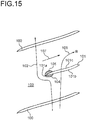
- a leading edge 101a of a splitter blade 101 works, that is, when a load is applied to the leading edge 101a of the splitter blade 101, in a vicinity of the leading edge 101a, a high-pressure region 104 is generated on a pressure surface 101b of the splitter blade 101 and a low pressure region 105 is generated on a suction surface 101c.
- the tip leakage flow 102 reaches near the leading edge 101a of the splitter blade 101, wraps around the leading edge 101a of the splitter blade 101 so as to avoid the high-pressure region 104, and further flows back progressively. Then a blockage area is formed, which reduces efficiency.
- Patent Documents 1 and 2 are not sufficient to decrease the two mechanisms.
- the tip leakage flow 106 leaking from the clearance between the splitter blade 101 and the casing is weakened and flows toward downstream of the flow passage 103 (in the direction of Arrow B) by the fluid 107 flowing the flow passage 103. Then it has been found that the multiple tip leakage flow is suppressed and the mechanisms can be reduced.
- an object of at least one embodiment of the present disclosure is to provide an impeller wheel which can improve efficiency of centrifugal compressors and a centrifugal compressor with the impeller wheel.
- the blade angle on the tip side edge of each short blade at the outlet portion is larger than the blade angle on the tip side edge of each long blade at the outlet portion, which can reduce the load of the short blade in comparison with the load of the long blade.
- the tip leakage flow leaking across the tip side edge of each long blade may not be reduced, the tip leakage flow leaking across the tip side edge of each short blade is reduced. Since the tip leakage flow which does not cross the tip side edge of each short blade flows toward the downstream of the flow passage by the fluid flowing through the flow passage. Thus, the multiple tip leakage flow is suppressed so as to improve efficiency of the centrifugal compressor.
- the difference between the blade angle on the tip side edge of each short blade at the outlet portion and the blade angle on the tip side edge of each long blade at the outlet portion is 5° or more. Since the load of each short blade can be reliably reduced in comparison with the load of each long blade, the multiple tip leakage flow is suppressed, which can improve efficiency of the centrifugal compressor.
- the multiple tip leakage flow is suppressed in the whole area of each short blade, which can further improve efficiency of the centrifugal compressor.
- the fluid flowing along a blade surface from the hub side toward the tip side leaks across the tip side edge, then the tip leakage flow is generated.
- the load of the short blades even on the hub side is reduced, which can further suppress the tip leakage flow.
- the difference between the blade angle on the tip side edge of each short blade at the outlet portion and the blade angle on the tip side edge of each long blade at the outlet portion is 5° or more. Since the load of each short blade on the hub side is reduced, the tip leakage flow can be further suppressed.
- a secondary flow toward the suction surface of each short blade is generated in a boundary layer in the vicinity of the hub.
- the secondary flow reaches the suction surface and flows toward the tip side edge along the suction surface of each short blade, which increases the tip leakage flow.
- the blade angle on the hub side edge of each short blade is smaller than the blade angle on the hub side of each long blade at the position of the leading edge of the short blade when the impeller wheel is viewed from the meridian plane direction. Since a deviation between the blade angle on hub side edge at the leading edge of each short blade becomes small, the secondary flow flowing on the suction surface is reduced, which can suppress the tip leakage flow. As a result, it is possible to further improve efficiency of the centrifugal compressor.
- the multiple tip leakage flow is suppressed, which can further improve efficiency of the centrifugal compressor.
- the blade angle on the tip side edge of each short blade at the outlet portion is larger than the blade angle on the tip side edge of each long blade at the outlet portion, which can reduce the load of the short blade in comparison with the load of the long blade.
- the tip leakage flow leaking across the tip side edge of each long blade may not be reduced, the tip leakage flow leaking across the tip side edge of each short blade is reduced. Since the tip leakage flow which does not cross the tip side edge of each short blade flows toward the downstream of the flow passage by the fluid flowing through the flow passage. Thus, the multiple tip leakage flow is suppressed so as to improve efficiency of the centrifugal compressor.
- an impeller wheel 1 includes a hub 2, a plurality of full blades 5, which is long blades, disposed on a circumferential surface of the hub 2 and extending from an inlet portion 3 to an outlet portion 4 of fluid, and a plurality of splitter blades 7, which is short blades, each disposed on the circumferential surface of the hub 2 and extending from a downstream side of leading edges 5a of the full blades 5 to the outlet portion 4 in a flow passage 6 formed between adjacent long blades 5,5.
- the impeller wheel 1 will be described as being provided in a centrifugal compressor of a turbocharger.
- the full blades 5 each have a leading edge 5a which is an edge on a side of the inlet portion 3, a trailing edge 5b which is an edge on a side of the outlet portion 4, a hub side edge 5c which is an edge on a side connecting with the hub 2, and a tip side edge 5d which is a side facing the hub side edge 5c.
- the splitter blades 7 each have a leading edge 7a which is an edge on a side of the inlet portion 3, a trailing edge 7b which is an edge on a side of the outlet portion 4, a hub side edge 7c which is an edge on a side connecting with the hub 2, and a tip side edge 7d which is a side facing the hub side edge 7c.
- the tip side edges 5d, 7d each face an inner wall surface of a casing not shown and each form a gap (hereinafter, referred to as "clearance") with the inner wall surface of the casing.
- FIG. 3 is a diagram for developing the respective tip side edges 5d, 7d of the full blades 5 and the splitter blades 7 on a plane along a rotation axis line L of the impeller wheel 1 (see FIG. 2 ) from the inlet portion 3 to the outlet portion 4.
- An angle ⁇ formed between the rotation axis line L and each of the full blades 5 and splitter blades 7 is defined as a blade angle.
- the blade angle ⁇ takes a value of 0 to 90° at an arbitrary position in a meridian plane length direction of the full blades 5 and the splitter blades 7 and at an arbitrary position in a blade height direction (in FIG. 2 , a direction from the hub side edges 5c, 7c to the tip side edges 5d, 7d).
- a ratio m of a length from the leading edge 5a of the full blades 5 in the meridian plane length direction to a meridian plane length of the full blades 5 is taken as the axis in the meridian plane length direction.
- FIG. 4 shows a distribution of the blade angles of the hub side edges 5c, 7c and the tip side edges 5d, 7d of the full blades 5 and the splitter blades 7 from the leading edges 5a, 7a to the tailing edges 5b, 7b.
- a blade angle ⁇ h,spl of the hub side edge 7c of each splitter blade 7 has the same distribution of a blade angle ⁇ h,full of the hub side edge 5c of each full blade 5 in a range of m LE ⁇ m ⁇ 1.
- the tip leakage flow 11 flows toward the downstream of the flow passage 6 by the fluid 12 flowing the downstream of the flow passage 6, which suppresses the multiple tip leakage flow by that amount. As a result, it is possible to improve efficiency of the centrifugal compressor.
- Embodiment 2 The impeller wheel according to Embodiment 2 is different from Embodiment 1 in that the distribution of the blade angles along the meridian plane length of the tip side edge 7d of each splitter blade 7 is modified.
- Embodiment 2 the same constituent elements as those in Embodiment 1 are associated with the same reference numerals and not described again in detail.
- the blade angle ⁇ s,spl on the tip side edge 7d of each splitter blade 7 is larger than the blade angle ⁇ s,full on the tip side edge 5d of each full blade 5 in the range of m LE ⁇ m ⁇ 1, that is, over the entire length of the splitter blade 7 ( ⁇ s,full ⁇ ⁇ s,spl ).
- the other configuration is the same as that of Embodiment 1.
- Embodiment 2 an expression ⁇ s,full ⁇ ⁇ s,spl is satisfied over the entire length of each splitter blade 7, thus the multiple tip leakage flow is securely suppressed in the whole area of the splitter blades 7. Accordingly, it is possible to further improve efficiency of the centrifugal compressor in comparison with Embodiment 1.
- Embodiment 3 will be described.
- the impeller wheel according to Embodiment 3 is different from each of Embodiments 1 and 2 in that the distribution of the blade angles along the meridian plane length of the tip side edge 7c of each splitter blade 7 is modified.
- Embodiment 3 will be described in an aspect in which the distribution of the blades along the meridian plane length of the hub side edge 7c of each splitter blade 7 is modified with respect to the configuration of Embodiment 2.
- Embodiment 3 can be described in an aspect in that the distribution of the blade angles along the meridian plane length of the hub side edge 7c of each splitter blade 7 is modified with respect to the configuration of Embodiment 1.
- the same constituent elements as those in Embodiments 1 and 2 are associated with the same reference numerals and not described again in detail.
- the tip leakage flow is generated by the fluid flowing along the blade surface from the hub side toward the tip side and leaking from the clearance over the tip side edges 5d, 7d (see FIG. 2 ).
- the load of the splitter blades 7 even on the hub side is reduced, which can further suppress the tip leakage flow.
- the difference between the blade angle ⁇ 2h,spl on the tip side edge 7d of each splitter blade 7 at the outlet portion 4 and the blade angle ⁇ 2h,full on the tip side edge 5d of each full blade 5 at the outlet portion 4 is 5° or more. Since the load of the splitter blades 7 even on the hub side can be reduced, the tip leakage flow can be further suppressed in comparison with Embodiment 2.
- Embodiment 4 The impeller wheel according to Embodiment 4 is different from Embodiment 3 in that the distribution of the blade angles along the meridian plane length of the tip side edge 7d of each splitter blade 7 is modified.
- Embodiment 4 the same constituent elements as those in Embodiments 1 to 3 are associated with the same reference numerals and not described again in detail.
- the blade angle ⁇ s,spl on the tip side edge 7d of each splitter blade 7 is larger than the blade angle ⁇ s,full on the tip side edge 5d of each full blade 5 in the range of m LE ⁇ m ⁇ 1, that is, over the entire length of the splitter blade 7 ( ⁇ s,full ⁇ ⁇ s,spl ).
- Embodiment 5 The impeller wheel according to Embodiment 5 is different from Embodiment 3 in that the distribution of the blade angles along the meridian plane length of the tip side edge 7c of each splitter blade 7 is modified.
- Embodiment 5 the same constituent elements as those in Embodiments 1 to 3 are associated with the same reference numerals and not described again in detail.
- a secondary flow 30 toward the suction surface 7f of each splitter blade 7 is generated in a boundary layer in the vicinity of the hub 2.
- the secondary flow 30 reaches the suction surface 7f and flows toward the tip side edge 7d (in the direction of Arrow P) along the suction surface 7f, which increases the tip leakage flow.
- Embodiment 6 the impeller wheel according to Embodiment 6 is different from Embodiment 4 in that the shape of the leading edge 7a of each splitter blade 7 is modified.
- Embodiment 6 the same constituent elements as those in Embodiments 1 to 4 are associated with the same reference numerals and not described again in detail.
- each splitter blade 7 includes a first portion 41 and a second portion 42 positioned radially outward from the first portion 41.
- an expression ⁇ 1 > ⁇ 2 is satisfied, where ⁇ 1 is an acute angle between a direction D 1 in which the first portion 41 extends and a rotational axis L of the impeller wheel 1 when viewed from the meridian plane, and ⁇ 2 is an acute angle between a direction D 2 in which the second portion 42 extends and the rotational axis L of the impeller wheel 1 when viewed from the meridian plane.
- the other configuration is the same as that of Embodiment 4.
- Embodiment 6 If the load of the leading edge 7a of each splitter blade 7 is reduced as in Embodiment 4, the work amount of the splitter blades 7 is decreased. However, according to Embodiment 6, since the leading edge 7a of each splitter blade 7 in the vicinity of the tip side edge 7d is inclined toward the inlet portion 3 side compared with the other parts, this portion becomes a region in which no work is performed, then the high pressure region (see the high pressure region 20 in FIG. 10 ) on the pressure surface 7e of the splitter blade 7 is hard to be formed. On the other hand, since the work in the other portion is performs, it is possible to suppress the multiple tip leakage flow while suppressing the decrease in the work amount.
Landscapes
- Engineering & Computer Science (AREA)
- Mechanical Engineering (AREA)
- General Engineering & Computer Science (AREA)
- Ceramic Engineering (AREA)
- Physics & Mathematics (AREA)
- Fluid Mechanics (AREA)
- Structures Of Non-Positive Displacement Pumps (AREA)
Abstract
Description
- The present disclosure relates to an impeller wheel and a centrifugal compressor having the impeller wheel.
- A centrifugal compressor used for industrial compressors, turbochargers, and the like compresses a fluid by rotating an impeller wheel radially installed a plurality of blades and is required to have a high efficiency, a high pressure ratio, and a large capacity. The capacity is defined by the minimum flow path area, which is a throat area, formed at an inlet of the impeller wheel, then it is possible to increase the flow capacity by reducing the number of blades and increasing the throat area. In contrast, it is possible to increase pressure ratio by increasing the number of the blades at an outlet portion of the impeller wheel.
- In particular, when the large capacity is required, the throat area is expanded by decreasing the number of long blades, which are full blades, and the number of blades at the outlet portion of the impeller wheel is increased by disposing each of short blades, which are splitter blades, which are shorter than the full blades, between adjacent full blades on downstream of leading edges of the full blades, which increases the pressure ratio.
- Generally, it is a basic design that the splitter blades are the same shape with the full blades. However, since the fluid flowing a fluid passage between the adjacent full blades does not necessarily flow along a surface of the full blades, a mismatch, which is a coincidence, between a direction which the fluid flows and a blade angle occurs at a leading edge of the splitter blades. In a case when a load at the leading edge of the splitter blades is increased, a strong pressure distribution occurs. When the coincidence is large, peeling occurs and causes deterioration in efficiency.
- Further, a gap, which is a clearance, exists between the impeller wheel and a casing covering the impeller wheel. Since a flow leaking from the clearance, which is a tip leakage flow, becomes an unintentional direction flow, which is a secondary flow, a shear layer is generated for a flow flowing the fluid passage, which is a main flow, and reduces efficiency. A pressure drop is incurred by forming a region in which the fluid hardly flows, which is a blockage area. Furthermore, the tip leakage flow forms a leakage vortex that is a vortex of a swirling flow, which is a longitudinal vortex, which causes deterioration in efficiency.
- In contrast, in
Patent Document 1, the coincidence at the leading edge is reduced by making the blade angle at the leading edge of the splitter blades larger than the blade angle of the full blades at the same position in a meridian plane, which improves efficiency. Further, inPatent Document 2, the splitter blades are not disposed on a line connecting between the leading edges of the full blades and the middle of the throat, which improves efficiency. -
- Patent Document 1:
JP2011-80411A - Patent Document 2:
JP5308319B - According to the
patent Documents - As shown in
FIG. 14 , a pressure gradient in which a pressure rises toward a flow direction A of a fluid is present in aflow passage 103 of an impeller wheel havingfull blades 100 and asplitter blade 101. Atip leakage flow 102 does not withstand the pressure gradient and flows back toward the upstream side of theflow path 103. The tip leakage flow flowing back further leaks through clearance between a next blade, which is one of thefull blades 100 or thesplitter blade 101, and a casing and further flows back. Thetip leakage flow 102 which repeatedly leaks next blades, which is a multiple tip leakage flow, accumulates losses every time the leakage is repeated. - As shown in
FIG. 15 , when a leadingedge 101a of asplitter blade 101 works, that is, when a load is applied to the leadingedge 101a of thesplitter blade 101, in a vicinity of the leadingedge 101a, a high-pressure region 104 is generated on apressure surface 101b of thesplitter blade 101 and alow pressure region 105 is generated on asuction surface 101c. Thetip leakage flow 102 reaches near the leadingedge 101a of thesplitter blade 101, wraps around the leadingedge 101a of thesplitter blade 101 so as to avoid the high-pressure region 104, and further flows back progressively. Then a blockage area is formed, which reduces efficiency. - As far as the clearance exists and the blade works, it is difficult to avoid the
tip leakage flow 102. The configurations ofPatent Documents splitter blade 101 is less than a load to thefull blades 100, although the tip leakage flow leaking from the clearance between thefull blades 100 and the casing cannot be reduced, thetip leakage flow 106 leaking from the clearance between thesplitter blade 101 and the casing is weakened and flows toward downstream of the flow passage 103 (in the direction of Arrow B) by thefluid 107 flowing theflow passage 103. Then it has been found that the multiple tip leakage flow is suppressed and the mechanisms can be reduced. - In view of the above, an object of at least one embodiment of the present disclosure is to provide an impeller wheel which can improve efficiency of centrifugal compressors and a centrifugal compressor with the impeller wheel.
- (1) An impeller wheel according to at least one embodiment of the present invention comprises:
- a hub;
- a plurality of long blades disposed on a circumferential surface of the hub, the plurality of long blades extending from an inlet portion to an outlet portion of fluid; and
- a plurality of short blades each disposed on the circumferential surface of the hub, the plurality of short blades extending from a downstream side of leading edges of the plurality of the long blades to the outlet portion in a flow passage formed between adjacent long blades of the plurality of long blades,
- wherein an expression β2s,full < β2s,spl is satisfied, where β2s,full and β2s,spl are respectively blade angles on tip side edges of each long blade and each short blade at the outlet portion.
- The larger the blade angle at the outlet portion, the smaller the total load, which is a total work amount, of the blades. According to the above configuration (1), the blade angle on the tip side edge of each short blade at the outlet portion is larger than the blade angle on the tip side edge of each long blade at the outlet portion, which can reduce the load of the short blade in comparison with the load of the long blade. As a result, although the tip leakage flow leaking across the tip side edge of each long blade may not be reduced, the tip leakage flow leaking across the tip side edge of each short blade is reduced. Since the tip leakage flow which does not cross the tip side edge of each short blade flows toward the downstream of the flow passage by the fluid flowing through the flow passage. Thus, the multiple tip leakage flow is suppressed so as to improve efficiency of the centrifugal compressor.
- (2) In some embodiments, in the above configuration (1),
an expression β2s,spl - β2s,full ≥ 5°is satisfied. - According to the above configuration (2), the difference between the blade angle on the tip side edge of each short blade at the outlet portion and the blade angle on the tip side edge of each long blade at the outlet portion is 5° or more. Since the load of each short blade can be reliably reduced in comparison with the load of each long blade, the multiple tip leakage flow is suppressed, which can improve efficiency of the centrifugal compressor.
- (3) In some embodiments, in the above configuration (1),
an expression βs,full < βs,spl is satisfied over an entire length of each short blade, where βs,full and βs,spl are respectively blade angles on the tip side edges of each long blade and the short blade at the same position when the impeller wheel is viewed from a meridian plane direction. - According to the above configuration (3), the multiple tip leakage flow is suppressed in the whole area of each short blade, which can further improve efficiency of the centrifugal compressor.
- (4) In some embodiments, in any one of the above configurations (1) to (3),
an expression β2h,spl - β2h,full ≥ 5°is satisfied where β2h,full and β2h,spl are respectively blade angles on hub side edges of each long blade and each short blade at the outlet portion. - The fluid flowing along a blade surface from the hub side toward the tip side leaks across the tip side edge, then the tip leakage flow is generated. Thus, the load of the short blades even on the hub side is reduced, which can further suppress the tip leakage flow. According to the above configuration (4), the difference between the blade angle on the tip side edge of each short blade at the outlet portion and the blade angle on the tip side edge of each long blade at the outlet portion is 5° or more. Since the load of each short blade on the hub side is reduced, the tip leakage flow can be further suppressed.
- (5) In some embodiments, in the above configuration (4),
an expression βs,spl,m=mLE - βs,full,m=mLE ≥ 5°is satisfied, where βs,full,m=mLE and βs,spl,m=mLE are respectively blade angles on the tip side edges of each long blades and each short blade at a position of a leading edge of the short blade when the impeller wheel is viewed from a meridian plane direction. - When a load is applied to the leading edge of each short blade, in a vicinity of the leading edge, a high pressure region having a high pressure is formed on a pressure surface side and a low pressure region having a low pressure is formed on a suction surface side. When the leak flow reaches the leading edge of each short blade, the tip leakage flow goes around the leading edge so as to avoid the high pressure region. Thus, the leakage is repeated. However, according to the above configuration (5), the difference between the blade angle on the tip side edge of each short blade and the blade angle of the on the tip side edge of each long blade at the leading edge of the short blade when the impeller wheel is viewed from the meridian plane direction, is 5° or more. Since the load on the leading edge of each short blade is reduced, it is difficult to form the high pressure region. As a result, the tip leakage flow which goes around the leading edge of each short blade is reduced. Since the tip leakage flow which reaches the leading edge of each short blade flows toward the downstream of the flow passage by the fluid flowing through the flow passage. Thus, the multiple tip leakage flow is suppressed so as to improve efficiency of the centrifugal compressor.
- (6) In some embodiments, in the above configuration (4),
an expression βh,full,m=mLE > βh,spl,m=mLE is satisfied, where βh,full,m=mLE and βh,spl,m=mLE are respectively blade angles on the hub side edges of each long blade and each short blade at a position of a leading edge of the short blade when the impeller wheel is viewed from a meridian plane direction. - A secondary flow toward the suction surface of each short blade is generated in a boundary layer in the vicinity of the hub. The secondary flow reaches the suction surface and flows toward the tip side edge along the suction surface of each short blade, which increases the tip leakage flow. However, according to the above configuration (6), the blade angle on the hub side edge of each short blade is smaller than the blade angle on the hub side of each long blade at the position of the leading edge of the short blade when the impeller wheel is viewed from the meridian plane direction. Since a deviation between the blade angle on hub side edge at the leading edge of each short blade becomes small, the secondary flow flowing on the suction surface is reduced, which can suppress the tip leakage flow. As a result, it is possible to further improve efficiency of the centrifugal compressor.
- (7) In some embodiments, in the above configuration (5),
the leading edge of each short blade includes a first portion and a second portion positioned radially outward from the first portion, and
an expression θ1 > θ2 is satisfied, where θ1 is an acute angle between a direction in which the first portion extends and a rotational axis of the impeller wheel when viewed from a meridian plane, and θ2 is an acute angle between a direction in which the second portion extends and the rotational axis of the impeller wheel when viewed from the meridian plane. - When the load on the leading edge of each short blade is reduced (in the above configuration (5)), the work amount of the short blades is decreased. However, according to the above configuration (7), since the leading edge of each short blade in the vicinity of the tip side edge is inclined toward the inlet portion side compared with the other parts, this portion becomes a region in which no work is performed, then the high pressure region is hard to be formed. On the other hand, since the work in the other portion is performs, it is possible to suppress the multiple tip leakage flow while suppressing the decrease in the work amount.
- (8) A centrifugal compressor according to at least one embodiment of the present invention comprises
the impeller wheel according to any one of the above (1) to (7). - According to the above configuration (8), the multiple tip leakage flow is suppressed, which can further improve efficiency of the centrifugal compressor.
- According to the at least one embodiment of the present disclosure, the blade angle on the tip side edge of each short blade at the outlet portion is larger than the blade angle on the tip side edge of each long blade at the outlet portion, which can reduce the load of the short blade in comparison with the load of the long blade. As a result, although the tip leakage flow leaking across the tip side edge of each long blade may not be reduced, the tip leakage flow leaking across the tip side edge of each short blade is reduced. Since the tip leakage flow which does not cross the tip side edge of each short blade flows toward the downstream of the flow passage by the fluid flowing through the flow passage. Thus, the multiple tip leakage flow is suppressed so as to improve efficiency of the centrifugal compressor.
-
-
FIG. 1 is a partial perspective view of an impeller wheel according toEmbodiment 1 of the present disclosure. -
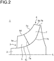
FIG. 2 is a view of a part of the impeller wheel according toEmbodiment 1 of the present disclosure from a meridian plane direction. -
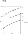
FIG. 3 is a diagram for defining a blade angle in the impeller wheel according toEmbodiment 1 of the present disclosure. -
FIG. 4 is a diagram showing the distribution of the respective blade angles of the full blades and the splitter blades of the impeller wheel according toEmbodiment 1 of the present disclosure. -
FIG. 5 is a diagram for describing the principle of suppressing multiple tip leakage flows in the impeller wheel according toEmbodiment 1 of the present disclosure. -
FIG. 6 is a graph showing a result of numerical calculation for efficiency of a centrifugal compressor having the impeller wheel according toEmbodiment 1 of the present disclosure. -
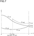
FIG. 7 is a diagram showing the distribution of the respective blade angles of the full blades and the splitter blades of the impeller wheel according toEmbodiment 2 of the present disclosure. -
FIG. 8 is a diagram showing the distribution of the respective blade angles of the full blades and the splitter blades of the impeller wheel according toEmbodiment 3 of the present disclosure. -
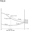
FIG. 9 is a diagram showing the distribution of the respective blade angles of the full blades and the splitter blades of the impeller wheel according toEmbodiment 4 of the present disclosure. -
FIG. 10 is a diagram for describing the principle of suppressing multiple tip leakage flows in the impeller wheel according toEmbodiment 4 of the present disclosure. -
FIG. 11 is a diagram showing the distribution of the respective blade angles of the full blades and the splitter blades of the impeller wheel according toEmbodiment 5 of the present disclosure. -
FIG. 12 is a diagram for describing the principle of suppressing tip leakage flows in the impeller wheel according toEmbodiment 5 of the present disclosure. -
FIG. 13 is a view of a part of the impeller wheel according toEmbodiment 6 of the present disclosure from a meridian plane direction. -
FIG. 14 is a diagram for describing a mechanism for the reason of efficiency reduction by disposing the splitter blades at the conventional impeller wheel. -
FIG. 15 is a diagram for describing another mechanism for the reason of efficiency reduction by disposing the splitter blades at the conventional impeller wheel. - Embodiments of the present invention will now be described in detail with reference to the accompanying drawings. However, the scope of the present invention is not limited to the following embodiments. It is intended that unless particularly specified, dimensions, materials, shapes, relative positions and the like of components described in the following embodiments shall be interpreted as illustrative only and not intended to limit the scope of the present invention unless particularly specified.
- As shown in
FIG. 1 , animpeller wheel 1 according toEmbodiment 1 includes ahub 2, a plurality offull blades 5, which is long blades, disposed on a circumferential surface of thehub 2 and extending from aninlet portion 3 to anoutlet portion 4 of fluid, and a plurality ofsplitter blades 7, which is short blades, each disposed on the circumferential surface of thehub 2 and extending from a downstream side of leadingedges 5a of thefull blades 5 to theoutlet portion 4 in aflow passage 6 formed between adjacentlong blades Embodiment 1, theimpeller wheel 1 will be described as being provided in a centrifugal compressor of a turbocharger. - As shown in
FIG. 2 , thefull blades 5 each have aleading edge 5a which is an edge on a side of theinlet portion 3, a trailingedge 5b which is an edge on a side of theoutlet portion 4, ahub side edge 5c which is an edge on a side connecting with thehub 2, and atip side edge 5d which is a side facing thehub side edge 5c. Thesplitter blades 7 each have aleading edge 7a which is an edge on a side of theinlet portion 3, a trailingedge 7b which is an edge on a side of theoutlet portion 4, ahub side edge 7c which is an edge on a side connecting with thehub 2, and atip side edge 7d which is a side facing thehub side edge 7c. Thetip side edges -
FIG. 3 is a diagram for developing the respectivetip side edges full blades 5 and thesplitter blades 7 on a plane along a rotation axis line L of the impeller wheel 1 (seeFIG. 2 ) from theinlet portion 3 to theoutlet portion 4. An angle β formed between the rotation axis line L and each of thefull blades 5 andsplitter blades 7 is defined as a blade angle. The blade angle β takes a value of 0 to 90° at an arbitrary position in a meridian plane length direction of thefull blades 5 and thesplitter blades 7 and at an arbitrary position in a blade height direction (inFIG. 2 , a direction from the hub side edges 5c, 7c to thetip side edges - In
FIG. 3 , a ratio m of a length from theleading edge 5a of thefull blades 5 in the meridian plane length direction to a meridian plane length of thefull blades 5 is taken as the axis in the meridian plane length direction. Based on the definition m, the position of theleading edge 5a becomes m = 0, and the position of the trailingedges leading edge 7a of thesplitter blades 7 is represented by m = mLE. -
FIG. 4 shows a distribution of the blade angles of the hub side edges 5c, 7c and thetip side edges full blades 5 and thesplitter blades 7 from the leadingedges hub side edge 7c of eachsplitter blade 7 has the same distribution of a blade angle βh,full of thehub side edge 5c of eachfull blade 5 in a range of mLE ≤ m ≤ 1. - A blade angle βs,full of the
tip side edge 5d of eachfull blade 5 decreases as m increases, and becomes the same as βh,full when m = 1. That is, an expression β2s,full = β2h,full is satisfied where β2s,full and β2h,full are respectively the blade angles β on thetip side edge 5d and thehub side edge 5c when m = 1. - A blade angle βs,spl on the
tip side edge 7d of eachsplitter blade 7 becomes the same as βh,full when m = mLE. That is, an expression βs,full,m=mLE = βh,full,m=mLE is satisfied where βs,full,m=mLE and βh,full,m=mLE are respectively the blade angles on thetip side edges tip side edge 7d at theoutlet portion 4, that is, m = 1. - The larger the blade angles at the
outlet portion 4, the smaller the total load, which is a total work amount, of the blades. According to the above configuration ofEmbodiment 1, since the blade angle β2s,spl on thetip side edge 7d of eachsplitter blade 7 at theoutlet portion 4 is larger than the blade angle β2s,full on thetip side edge 5d of eachfull blade 5 at the outlet portion 4 (β2s,full < β2s,spl), the load of thesplitter blade 7 can be reduced in comparison with the load of thefull blade 5. Accordingly, as shown inFIG. 5 , even if thetip leakage flow 10 leaking the clearance so as to across thetip side edge 5d of eachfull blade 5 is not reduced, thetip leakage flow 11 leaking the clearance so as to across thetip side edge 7d of eachsplitter blade 7. Thus, thetip leakage flow 11 flows toward the downstream of theflow passage 6 by the fluid 12 flowing the downstream of theflow passage 6, which suppresses the multiple tip leakage flow by that amount. As a result, it is possible to improve efficiency of the centrifugal compressor. - The effect of improving efficiency of the centrifugal compressor when β2s,full < β2s,spl is confirmed by numerical calculation. The results are shown in
FIG. 6. FIG. 6 shows the relationship between the difference Δβ2s (= β2s,spl - β2s,full) between the blade angle β2s,spl on thetip edge side 7d of eachsplitter blade 7 and the blade angle β2s,full on thetip edge side 5d of eachfull blade 5 at theoutlet portion 4, and the efficiency of the centrifugal compressor. In case of Δβ2s = 0, the blade angle β2s,spl on thetip side edge 7d of eachsplitter blade 7 is the same as the blade angle β2s,full on thetip side edge 5d of eachfull blade 5 at the outlet portion4. In this case, under the condition of β2s,full < β2s,spl, the efficiency of the centrifugal compressor is improved in the range of Δβ2s ≤ 17°as compared with the case of Δβ2s = 0°. In order to reliably improve the efficiency of the centrifugal compressor as compared with the case of Δβ2s = 0°, the range of Δβ2s ≥ 5°is preferable. The range of 5° ≤ Δβ2s ≤ 13 is more preferable. - Next, the impeller wheel according to
Embodiment 2 will be described. The impeller wheel according toEmbodiment 2 is different fromEmbodiment 1 in that the distribution of the blade angles along the meridian plane length of thetip side edge 7d of eachsplitter blade 7 is modified. InEmbodiment 2, the same constituent elements as those inEmbodiment 1 are associated with the same reference numerals and not described again in detail. - As shown in
FIG. 7 , the blade angle βs,spl on thetip side edge 7d of eachsplitter blade 7 is larger than the blade angle βs,full on thetip side edge 5d of eachfull blade 5 in the range of mLE ≤ m ≤ 1, that is, over the entire length of the splitter blade 7 (βs,full < βs,spl). The other configuration is the same as that ofEmbodiment 1. - In
Embodiment 2, an expression βs,full < βs,spl is satisfied over the entire length of eachsplitter blade 7, thus the multiple tip leakage flow is securely suppressed in the whole area of thesplitter blades 7. Accordingly, it is possible to further improve efficiency of the centrifugal compressor in comparison withEmbodiment 1. - Next, the impeller wheel according to
Embodiment 3 will be described. The impeller wheel according toEmbodiment 3 is different from each ofEmbodiments tip side edge 7c of eachsplitter blade 7 is modified. In the following description,Embodiment 3 will be described in an aspect in which the distribution of the blades along the meridian plane length of thehub side edge 7c of eachsplitter blade 7 is modified with respect to the configuration ofEmbodiment 2. However,Embodiment 3 can be described in an aspect in that the distribution of the blade angles along the meridian plane length of thehub side edge 7c of eachsplitter blade 7 is modified with respect to the configuration ofEmbodiment 1. InEmbodiment 3, the same constituent elements as those inEmbodiments - As shown in
FIG. 8 , an expression β2h,spl- β2h,full≥ 5°is satisfied at theoutlet portion 4, that is, m = 1. The other configuration is the same as that ofEmbodiment 2. - The tip leakage flow is generated by the fluid flowing along the blade surface from the hub side toward the tip side and leaking from the clearance over the
tip side edges FIG. 2 ). Thus, the load of thesplitter blades 7 even on the hub side is reduced, which can further suppress the tip leakage flow. InEmbodiment 3, the difference between the blade angle β2h,spl on thetip side edge 7d of eachsplitter blade 7 at theoutlet portion 4 and the blade angle β2h,full on thetip side edge 5d of eachfull blade 5 at theoutlet portion 4 is 5° or more. Since the load of thesplitter blades 7 even on the hub side can be reduced, the tip leakage flow can be further suppressed in comparison withEmbodiment 2. - Next, the impeller wheel according to
Embodiment 4 will be described. The impeller wheel according toEmbodiment 4 is different fromEmbodiment 3 in that the distribution of the blade angles along the meridian plane length of thetip side edge 7d of eachsplitter blade 7 is modified. InEmbodiment 4, the same constituent elements as those inEmbodiments 1 to 3 are associated with the same reference numerals and not described again in detail. - As shown in
FIG. 9 , the blade angle βs,spl on thetip side edge 7d of eachsplitter blade 7 is larger than the blade angle βs,full on thetip side edge 5d of eachfull blade 5 in the range of mLE ≤ m ≤ 1, that is, over the entire length of the splitter blade 7 (βs,full < βs,spl). Further, an expression βs,spl,m=mLE - βs,full,m=mLE ≥ 5°is satisfied where βs,full,m=mLE and βs,spl,m=mLE are respectively the blade angles on thetip side edge 5d of thefull blade 5 and on thetip side edge 7d of thesplitter blade 7 at m = mLE. The other configuration is the same as that ofEmbodiment 3. - As shown in
FIG. 10 , when a load is applied to theleading edge 7a of eachsplitter blade 7, in a vicinity of theleading edge 7a, ahigh pressure region 20 having a high pressure is formed on a side of apressure surface 7e and alow pressure region 21 having a low pressure is formed on a side of asuction surface 7f. When theleak flow 10 reaches theleading edge 7a, thetip leakage flow 10 goes around theleading edge 7a so as to avoid thehigh pressure region 20. Thus, the leakage is repeated. However, inEmbodiment 4, the expression βs,spl,m=mLE - βs,full,m=mLE ≥ 5°is satisfied where m = mLE. Since the load of theleading edge 7a is reduced, it is difficult to form thehigh pressure region 20. As a result, thetip leakage flow 10 which goes around theleading edge 7a is reduced. Thetip leakage flow 13 leaking from the clearance across thetip side edge 7d of eachsplitter blade 7 is weakened and flows toward downstream of theflow passage 6 by the fluid 12 flowing theflow passage 6. Then the multiple tip leakage flow is suppressed, which improves efficiency of the centrifugal compressor. - Next, the impeller wheel according to
Embodiment 5 will be described. The impeller wheel according toEmbodiment 5 is different fromEmbodiment 3 in that the distribution of the blade angles along the meridian plane length of thetip side edge 7c of eachsplitter blade 7 is modified. InEmbodiment 5, the same constituent elements as those inEmbodiments 1 to 3 are associated with the same reference numerals and not described again in detail. - As shown in
FIG. 11 , an expression βh,full,m=mLE > βh,spl,m=mLE is satisfied where βh,full,m=mLE is the blade angle on thehub side edge 5c of eachfull blade 5 and βh,spl,m=mLE is the blade angle on thehub side edge 7c of eachsplitter blade 7 when m = mLE. The other configuration is the same as that ofEmbodiment 3. - In shown in
FIG. 12 , asecondary flow 30 toward thesuction surface 7f of eachsplitter blade 7 is generated in a boundary layer in the vicinity of thehub 2. Thesecondary flow 30 reaches thesuction surface 7f and flows toward thetip side edge 7d (in the direction of Arrow P) along thesuction surface 7f, which increases the tip leakage flow. However, inEmbodiment 5, the expression βh,full,m=mLE > βh,spl,m=mLE is satisfied where m = mLE. Since a deviation between the blade angle on thehub side edge 7c at theleading edge 7a of eachsplitter blade 7 and a direction of thesecondary flow 30 becomes small, thesecondary flow 30 flowing on thesuction surface 7f is reduced, which can suppress the tip leakage flow. As a result, it is possible to further improve efficiency of the centrifugal compressor. - Next, the impeller wheel according to
Embodiment 6 will be described. The impeller wheel according toEmbodiment 6 is different fromEmbodiment 4 in that the shape of theleading edge 7a of eachsplitter blade 7 is modified. InEmbodiment 6, the same constituent elements as those inEmbodiments 1 to 4 are associated with the same reference numerals and not described again in detail. - As shown in
FIG. 13 , theleading edge 7a of eachsplitter blade 7 includes afirst portion 41 and a second portion 42 positioned radially outward from thefirst portion 41. an expression θ1 > θ2 is satisfied, where θ1 is an acute angle between a direction D1 in which thefirst portion 41 extends and a rotational axis L of theimpeller wheel 1 when viewed from the meridian plane, and θ2 is an acute angle between a direction D2 in which the second portion 42 extends and the rotational axis L of theimpeller wheel 1 when viewed from the meridian plane. The other configuration is the same as that ofEmbodiment 4. - If the load of the
leading edge 7a of eachsplitter blade 7 is reduced as inEmbodiment 4, the work amount of thesplitter blades 7 is decreased. However, according toEmbodiment 6, since theleading edge 7a of eachsplitter blade 7 in the vicinity of thetip side edge 7d is inclined toward theinlet portion 3 side compared with the other parts, this portion becomes a region in which no work is performed, then the high pressure region (see thehigh pressure region 20 inFIG. 10 ) on thepressure surface 7e of thesplitter blade 7 is hard to be formed. On the other hand, since the work in the other portion is performs, it is possible to suppress the multiple tip leakage flow while suppressing the decrease in the work amount.
Claims (8)
- An impeller wheel comprising:a hub;a plurality of long blades disposed on a circumferential surface of the hub, the plurality of long blades extending from an inlet portion to an outlet portion of fluid; anda plurality of short blades each disposed on the circumferential surface of the hub, the plurality of short blades extending from a downstream side of leading edges of the plurality of the long blades to the outlet portion in a flow passage formed between adjacent long blades of the plurality of long blades,wherein an expression β2s,full < β2s,spl is satisfied, where β2s,full and β2s,spl are respectively blade angles on tip side edges of each long blade and each short blade at the outlet portion.
- The impeller wheel according to claim 1,
wherein an expression β2s,spl - β2s,full ≥ 5°is satisfied. - The impeller wheel according to claim 1 or 2,
wherein an expression βs,full < βs,spl is satisfied over an entire length of each short blade,
where βs,full and βs,spl are respectively blade angles on the tip side edges of each long blade and the short blade at the same position when the impeller wheel is viewed from a meridian plane direction. - The impeller wheel according to any one of claims 1 to 3,
wherein an expression β2h,spl - β2h,full ≥ 5°is satisfied where β2h,full and β2h,spl are respectively blade angles on hub side edges of each long blade and each short blade at the outlet portion. - The impeller wheel according to claim 4,
wherein an expression βs,spl,m=mLE - βs,full,m=mLE ≥ 5°is satisfied, where βs,full,m=mLE and βs,spl,m=mLE are respectively blade angles on the tip side edges of each long blade and each short blade at a position of a leading edge of the short blade when the impeller wheel is viewed from a meridian plane direction. - The impeller wheel according to claim 4,
wherein an expression βh,full,m=mLE > βh,spl,m=mLE is satisfied, where βh,full,m=mLE and βh,spl,m=mLE are respectively blade angles on the hub side edges of each long blade and each short blade at a position of a leading edge of the short blade when the impeller wheel is viewed from a meridian plane direction. - The impeller wheel according to claim 5,
wherein the leading edge of each short blade includes a first portion and a second portion positioned radially outward from the first portion, and
wherein an expression θ1 > θ2 is satisfied, where θ1 is an acute angle between a direction in which the first portion extends and a rotational axis of the impeller wheel when viewed from a meridian plane, and θ2 is an acute angle between a direction in which the second portion extends and the rotational axis of the impeller wheel when viewed from the meridian plane. - A centrifugal compressor comprising:the impeller wheel according to any one of claims 1 to 7.
Applications Claiming Priority (1)
| Application Number | Priority Date | Filing Date | Title |
|---|---|---|---|
| JP2018038627A JP6740271B2 (en) | 2018-03-05 | 2018-03-05 | Impeller and centrifugal compressor equipped with this impeller |
Publications (1)
| Publication Number | Publication Date |
|---|---|
| EP3536973A1 true EP3536973A1 (en) | 2019-09-11 |
Family
ID=65351921
Family Applications (1)
| Application Number | Title | Priority Date | Filing Date |
|---|---|---|---|
| EP19155710.7A Withdrawn EP3536973A1 (en) | 2018-03-05 | 2019-02-06 | Impeller wheel and centrifugal compressor having impeller wheel |
Country Status (4)
| Country | Link |
|---|---|
| US (1) | US10801514B2 (en) |
| EP (1) | EP3536973A1 (en) |
| JP (1) | JP6740271B2 (en) |
| CN (1) | CN110230609B (en) |
Families Citing this family (12)
| Publication number | Priority date | Publication date | Assignee | Title |
|---|---|---|---|---|
| US11408435B2 (en) * | 2018-06-22 | 2022-08-09 | Mitsubishi Heavy Industries Engine & Turbocharger, Ltd. | Rotor and centrifugal compressor including the same |
| JP7140030B2 (en) * | 2019-03-28 | 2022-09-21 | 株式会社豊田自動織機 | Centrifugal compressor for fuel cell |
| CN115380169B (en) * | 2020-04-23 | 2026-02-17 | 三菱重工船用机械株式会社 | Impeller and centrifugal compressor |
| JP2022056948A (en) * | 2020-09-30 | 2022-04-11 | 株式会社豊田自動織機 | Centrifugal compressor |
| CN112392733A (en) * | 2020-11-30 | 2021-02-23 | 襄阳五二五泵业有限公司 | Impeller for foam delivery pump |
| CN112943686B (en) * | 2021-02-08 | 2023-06-23 | 中国科学院工程热物理研究所 | A centrifugal compressor impeller and its design method |
| CN218934766U (en) * | 2021-04-19 | 2023-04-28 | 博隆能源股份有限公司 | Centrifugal blower, fuel cell system and impeller |
| GB2611561A (en) | 2021-10-08 | 2023-04-12 | Cummins Ltd | Compressor impeller |
| CN114087229B (en) * | 2021-11-15 | 2023-03-24 | 珠海格力电器股份有限公司 | Compression impeller and air cycle machine |
| TW202405311A (en) | 2022-06-03 | 2024-02-01 | 美商博隆能源股份有限公司 | Centrifugal blower including shrouded mixed flow impeller for enhanced cooling |
| IT202300021351A1 (en) * | 2023-10-13 | 2025-04-13 | Ferrari Spa | FUEL CELL-POWERED MOTOR VEHICLE WITH IMPROVED SOUND EMISSION |
| US12571403B2 (en) * | 2024-08-02 | 2026-03-10 | Pratt & Whitney Canada Corp. | Non-linear impeller backsweep |
Citations (7)
| Publication number | Priority date | Publication date | Assignee | Title |
|---|---|---|---|---|
| GB941343A (en) * | 1961-08-29 | 1963-11-13 | Rudolph Birmann | Improvements in or relating to impeller blading for centrifugal compressors |
| JPS538319B2 (en) | 1972-09-25 | 1978-03-27 | ||
| US6508626B1 (en) * | 1998-05-27 | 2003-01-21 | Ebara Corporation | Turbomachinery impeller |
| JP2008196381A (en) * | 2007-02-13 | 2008-08-28 | Mitsubishi Heavy Ind Ltd | Impeller for centrifugal compressor and centrifugal compressor |
| JP2011008041A (en) | 2009-06-26 | 2011-01-13 | Nippon Shokubai Co Ltd | Optical film and image-display device equipped with the same |
| US20130195667A1 (en) * | 2010-12-13 | 2013-08-01 | Mitsubishi Heavy Industries, Ltd. | Impeller for centrifugal compressor |
| US20130266450A1 (en) * | 2010-12-28 | 2013-10-10 | Mitsubishi Heavy Industries, Ltd. | Centrifugal compressor |
Family Cites Families (10)
| Publication number | Priority date | Publication date | Assignee | Title |
|---|---|---|---|---|
| US4093401A (en) * | 1976-04-12 | 1978-06-06 | Sundstrand Corporation | Compressor impeller and method of manufacture |
| JP4115180B2 (en) * | 2002-07-11 | 2008-07-09 | 三菱重工業株式会社 | Impeller and centrifugal compressor |
| FR2946399B1 (en) * | 2009-06-05 | 2016-05-13 | Turbomeca | CENTRIFUGAL COMPRESSOR WHEEL. |
| JP5495700B2 (en) | 2009-10-07 | 2014-05-21 | 三菱重工業株式会社 | Centrifugal compressor impeller |
| JP5308319B2 (en) | 2009-12-02 | 2013-10-09 | 三菱重工業株式会社 | Centrifugal compressor impeller |
| JP5606515B2 (en) * | 2012-12-13 | 2014-10-15 | 三菱重工業株式会社 | Compressor |
| EP3239489B1 (en) * | 2014-12-11 | 2021-08-11 | Kawasaki Jukogyo Kabushiki Kaisha | Impeller for supercharger |
| CN105650032B (en) * | 2016-03-29 | 2017-11-07 | 浙江理工大学 | The diffuser of centrifugal compressor |
| JP2017193982A (en) * | 2016-04-19 | 2017-10-26 | 本田技研工業株式会社 | compressor |
| US10669854B2 (en) * | 2017-08-18 | 2020-06-02 | Pratt & Whitney Canada Corp. | Impeller |
-
2018
- 2018-03-05 JP JP2018038627A patent/JP6740271B2/en active Active
-
2019
- 2019-02-01 CN CN201910103192.1A patent/CN110230609B/en not_active Expired - Fee Related
- 2019-02-04 US US16/266,371 patent/US10801514B2/en not_active Expired - Fee Related
- 2019-02-06 EP EP19155710.7A patent/EP3536973A1/en not_active Withdrawn
Patent Citations (7)
| Publication number | Priority date | Publication date | Assignee | Title |
|---|---|---|---|---|
| GB941343A (en) * | 1961-08-29 | 1963-11-13 | Rudolph Birmann | Improvements in or relating to impeller blading for centrifugal compressors |
| JPS538319B2 (en) | 1972-09-25 | 1978-03-27 | ||
| US6508626B1 (en) * | 1998-05-27 | 2003-01-21 | Ebara Corporation | Turbomachinery impeller |
| JP2008196381A (en) * | 2007-02-13 | 2008-08-28 | Mitsubishi Heavy Ind Ltd | Impeller for centrifugal compressor and centrifugal compressor |
| JP2011008041A (en) | 2009-06-26 | 2011-01-13 | Nippon Shokubai Co Ltd | Optical film and image-display device equipped with the same |
| US20130195667A1 (en) * | 2010-12-13 | 2013-08-01 | Mitsubishi Heavy Industries, Ltd. | Impeller for centrifugal compressor |
| US20130266450A1 (en) * | 2010-12-28 | 2013-10-10 | Mitsubishi Heavy Industries, Ltd. | Centrifugal compressor |
Also Published As
| Publication number | Publication date |
|---|---|
| JP2019152166A (en) | 2019-09-12 |
| US20190271326A1 (en) | 2019-09-05 |
| US10801514B2 (en) | 2020-10-13 |
| CN110230609A (en) | 2019-09-13 |
| JP6740271B2 (en) | 2020-08-12 |
| CN110230609B (en) | 2020-12-15 |
Similar Documents
| Publication | Publication Date | Title |
|---|---|---|
| US10801514B2 (en) | Impeller wheel and centrifugal compressor having impeller wheel | |
| EP2314876B1 (en) | Radial turbo-machine | |
| EP2020509B1 (en) | Centrifugal compressor, impeller and operating method of the same | |
| US9638208B2 (en) | Centrifugal compressor | |
| US8317466B2 (en) | Blade structure of gas turbine | |
| KR20110106946A (en) | Impeller of centrifugal compressor | |
| EP3536972B1 (en) | Centrifugal compressor and turbocharger | |
| US10208765B2 (en) | Gas turbine axial compressor | |
| CN103998790A (en) | Centrifugal compressor | |
| EP2535596B1 (en) | Centrifugal compressor using an asymmetric self-recirculating casing treatment | |
| JP2008075536A (en) | Centrifugal compressor | |
| JP2012052432A (en) | Diffuser for centrifugal compressor and centrifugal compressor with the same | |
| JP2008075536A5 (en) | ||
| JP2009133267A (en) | Impeller of compressor | |
| CN112412883A (en) | Vane Diffusers and Centrifugal Compressors | |
| EP4112944B1 (en) | Impeller and centrifugal compressor | |
| US12435730B2 (en) | Impeller of centrifugal compressor and centrifugal compressor | |
| EP3530957B1 (en) | Compressor and turbocharger | |
| EP3708847B1 (en) | Centrifugal compressor and turbocharger comprising said centrifugal compressor | |
| US11428240B2 (en) | Centrifugal compressor and turbocharger including the same | |
| JP4893125B2 (en) | Double suction centrifugal pump | |
| JP3993371B2 (en) | Runner blade of mixed flow hydraulic machine |
Legal Events
| Date | Code | Title | Description |
|---|---|---|---|
| PUAI | Public reference made under article 153(3) epc to a published international application that has entered the european phase |
Free format text: ORIGINAL CODE: 0009012 |
|
| STAA | Information on the status of an ep patent application or granted ep patent |
Free format text: STATUS: REQUEST FOR EXAMINATION WAS MADE |
|
| 17P | Request for examination filed |
Effective date: 20190206 |
|
| AK | Designated contracting states |
Kind code of ref document: A1 Designated state(s): AL AT BE BG CH CY CZ DE DK EE ES FI FR GB GR HR HU IE IS IT LI LT LU LV MC MK MT NL NO PL PT RO RS SE SI SK SM TR |
|
| AX | Request for extension of the european patent |
Extension state: BA ME |
|
| RBV | Designated contracting states (corrected) |
Designated state(s): AL AT BE BG CH CY CZ DE DK EE ES FI FR GB GR HR HU IE IS IT LI LT LU LV MC MK MT NL NO PL PT RO RS SE SI SK SM TR |
|
| STAA | Information on the status of an ep patent application or granted ep patent |
Free format text: STATUS: EXAMINATION IS IN PROGRESS |
|
| 17Q | First examination report despatched |
Effective date: 20210504 |
|
| STAA | Information on the status of an ep patent application or granted ep patent |
Free format text: STATUS: THE APPLICATION IS DEEMED TO BE WITHDRAWN |
|
| 18D | Application deemed to be withdrawn |
Effective date: 20240903 |