EP3536936A1 - Vehicle control device - Google Patents
Vehicle control device Download PDFInfo
- Publication number
- EP3536936A1 EP3536936A1 EP17879404.6A EP17879404A EP3536936A1 EP 3536936 A1 EP3536936 A1 EP 3536936A1 EP 17879404 A EP17879404 A EP 17879404A EP 3536936 A1 EP3536936 A1 EP 3536936A1
- Authority
- EP
- European Patent Office
- Prior art keywords
- reaction force
- muscle
- accelerator pedal
- value
- depression
- Prior art date
- Legal status (The legal status is an assumption and is not a legal conclusion. Google has not performed a legal analysis and makes no representation as to the accuracy of the status listed.)
- Granted
Links
Images









Classifications
-
- B—PERFORMING OPERATIONS; TRANSPORTING
- B60—VEHICLES IN GENERAL
- B60K—ARRANGEMENT OR MOUNTING OF PROPULSION UNITS OR OF TRANSMISSIONS IN VEHICLES; ARRANGEMENT OR MOUNTING OF PLURAL DIVERSE PRIME-MOVERS IN VEHICLES; AUXILIARY DRIVES FOR VEHICLES; INSTRUMENTATION OR DASHBOARDS FOR VEHICLES; ARRANGEMENTS IN CONNECTION WITH COOLING, AIR INTAKE, GAS EXHAUST OR FUEL SUPPLY OF PROPULSION UNITS IN VEHICLES
- B60K26/00—Arrangement or mounting of propulsion-unit control devices in vehicles
- B60K26/02—Arrangement or mounting of propulsion-unit control devices in vehicles of initiating means or elements
- B60K26/021—Arrangement or mounting of propulsion-unit control devices in vehicles of initiating means or elements with means for providing feel, e.g. by changing pedal force characteristics
-
- B—PERFORMING OPERATIONS; TRANSPORTING
- B60—VEHICLES IN GENERAL
- B60K—ARRANGEMENT OR MOUNTING OF PROPULSION UNITS OR OF TRANSMISSIONS IN VEHICLES; ARRANGEMENT OR MOUNTING OF PLURAL DIVERSE PRIME-MOVERS IN VEHICLES; AUXILIARY DRIVES FOR VEHICLES; INSTRUMENTATION OR DASHBOARDS FOR VEHICLES; ARRANGEMENTS IN CONNECTION WITH COOLING, AIR INTAKE, GAS EXHAUST OR FUEL SUPPLY OF PROPULSION UNITS IN VEHICLES
- B60K26/00—Arrangement or mounting of propulsion-unit control devices in vehicles
- B60K26/02—Arrangement or mounting of propulsion-unit control devices in vehicles of initiating means or elements
-
- F—MECHANICAL ENGINEERING; LIGHTING; HEATING; WEAPONS; BLASTING
- F02—COMBUSTION ENGINES; HOT-GAS OR COMBUSTION-PRODUCT ENGINE PLANTS
- F02D—CONTROLLING COMBUSTION ENGINES
- F02D11/00—Arrangements for, or adaptations to, non-automatic engine control initiation means, e.g. operator initiated
- F02D11/06—Arrangements for, or adaptations to, non-automatic engine control initiation means, e.g. operator initiated characterised by non-mechanical control linkages, e.g. fluid control linkages or by control linkages with power drive or assistance
- F02D11/10—Arrangements for, or adaptations to, non-automatic engine control initiation means, e.g. operator initiated characterised by non-mechanical control linkages, e.g. fluid control linkages or by control linkages with power drive or assistance of the electric type
-
- F—MECHANICAL ENGINEERING; LIGHTING; HEATING; WEAPONS; BLASTING
- F02—COMBUSTION ENGINES; HOT-GAS OR COMBUSTION-PRODUCT ENGINE PLANTS
- F02D—CONTROLLING COMBUSTION ENGINES
- F02D11/00—Arrangements for, or adaptations to, non-automatic engine control initiation means, e.g. operator initiated
- F02D11/06—Arrangements for, or adaptations to, non-automatic engine control initiation means, e.g. operator initiated characterised by non-mechanical control linkages, e.g. fluid control linkages or by control linkages with power drive or assistance
- F02D11/10—Arrangements for, or adaptations to, non-automatic engine control initiation means, e.g. operator initiated characterised by non-mechanical control linkages, e.g. fluid control linkages or by control linkages with power drive or assistance of the electric type
- F02D11/106—Detection of demand or actuation
-
- B—PERFORMING OPERATIONS; TRANSPORTING
- B60—VEHICLES IN GENERAL
- B60K—ARRANGEMENT OR MOUNTING OF PROPULSION UNITS OR OF TRANSMISSIONS IN VEHICLES; ARRANGEMENT OR MOUNTING OF PLURAL DIVERSE PRIME-MOVERS IN VEHICLES; AUXILIARY DRIVES FOR VEHICLES; INSTRUMENTATION OR DASHBOARDS FOR VEHICLES; ARRANGEMENTS IN CONNECTION WITH COOLING, AIR INTAKE, GAS EXHAUST OR FUEL SUPPLY OF PROPULSION UNITS IN VEHICLES
- B60K26/00—Arrangement or mounting of propulsion-unit control devices in vehicles
- B60K26/02—Arrangement or mounting of propulsion-unit control devices in vehicles of initiating means or elements
- B60K26/021—Arrangement or mounting of propulsion-unit control devices in vehicles of initiating means or elements with means for providing feel, e.g. by changing pedal force characteristics
- B60K2026/023—Arrangement or mounting of propulsion-unit control devices in vehicles of initiating means or elements with means for providing feel, e.g. by changing pedal force characteristics with electrical means to generate counter force or torque
Definitions
- the present disclosure relates to a vehicle control device capable of controlling a reaction force value of an accelerator pedal depending on muscle activity of a driver.
- a depression amount of an accelerator pedal and a reaction force value are set to have a substantially proportional relationship, generally, a driver recognizes a depression amount of an accelerator pedal by a reaction force value to be applied from the accelerator pedal. Therefore, there is proposed a reaction force control device configured such that a driver's operation of depressing an accelerator pedal is guided depending on a driver's preference or a driving environment by changing a reaction force value of the accelerator pedal.
- a vehicle driving operation assist device of Patent Literature 1 dynamically generates a driving intention sequence of a plurality of virtual drivers in a predetermined time zone in the past including a current point of time, calculates a driving operation amount sequence approximation degree representing a sequential approximation degree between a driving operation amount of a virtual driver and a driving operation amount of an actual driver for each driving intention sequence, estimates an actual driver's driving intention by comparing a plurality of driving operation amount sequence approximation degrees, and estimates an actual driver's state on the basis of the estimated driving intention.
- a reaction force command value of the accelerator pedal is speedily lowered, as an elapsed time from a point of time when a driver intends to change a lane until a driver's driving intention is estimated to be changing a lane increases.
- a vehicle accelerator pedal control device of Patent Literature 2 includes a reaction force setting means having a three-dimensional map, which is defined by a depression amount of an accelerator pedal, a depression speed of the accelerator pedal, and a reaction force value to be applied to a driver; and a depression speed detection means for detecting a depression speed of the accelerator pedal, wherein the reaction force setting means sets reaction force characteristics in such a way that a reaction force value of the accelerator pedal decreases, when a depression speed is high, as compared with a case where a depression speed is low.
- reaction force characteristics suitable for a driving environment or a driving intention, while alleviating burden and incongruity of a driver.
- a driver's operation of depressing and returning an accelerator pedal may be regarded as plantar flexion motion and dorsiflexion motion of an ankle joint in terms of muscle activity.
- an operation of an accelerator pedal by an ankle joint mainly involves an anterior tibialis muscle t, a soleus muscle s, and a gastrocnemius muscle g.
- the anterior tibialis muscle t is a single articular muscle (one articular muscle) which performs dorsiflexion motion of an ankle joint
- the soleus muscle s is a single articular muscle which performs plantar flexion motion of an ankle joint.
- the gastrocnemius muscle g is a bilateral muscle which performs plantar flexion motion of an ankle joint and performs flexion motion of a knee joint.
- a single articular muscle depends on a mechanical force ratio, and has a resistance to weight of raising a body against a gravitational force.
- a bilateral muscle suppresses mechanical energy consumption, controls a direction of an external force, and has so-called propulsion capability of propelling a body in a specific direction.
- a skeletal muscle Since a skeletal muscle has viscoelastic properties as mechanical properties, it is known that the skeletal muscle can be expressed by a two-element model constituted of a series elastic element and a contraction element; an elastic modulus of a series elastic element increases, as a muscle tension increases; there is a hyperbolic relationship between a load and a speed of a contraction element: and stiffness of the entirety of muscle has a linear relationship with respect to muscle activity.
- the accelerator pedal control device of Patent Literature 1 can determine a driver's driving intention by using a depression speed of an accelerator pedal as a parameter, and set reaction force characteristics suitable for the driving intention.
- Patent Literature 2 Although it is possible to acquire a reaction force value of an accelerator pedal suitable for a driver's driving intention, there may occur a discrepancy between an operation amount (a physical reaction force value to be applied to a driver) with which a driver actually operates an accelerator pedal, and a reaction force perception amount which the driver instinctively feels from the accelerator pedal.
- an operation amount a physical reaction force value to be applied to a driver
- a reaction force perception amount which the driver instinctively feels from the accelerator pedal.
- F-S characteristics a correlation between a reaction force value of an accelerator pedal suitable for a driver, and a depression amount is set in a specific depression speed in driving a vehicle, in a case where a driving condition changes, and a depression speed changes, F-S characteristics suitable for a driver may not be necessarily acquired.
- An object of the present disclosure is to provide a vehicle control device and the like, which let a driver sufficiently and instinctively perceive a feeling of operating an accelerator pedal, regardless of a depression speed of the accelerator pedal.
- a vehicle control device includes a depression amount detection unit for detecting a depression amount of an accelerator pedal; a depression speed detection unit for detecting a depression speed of the accelerator pedal; a reaction force setting unit for setting a value of a reaction force of the accelerator pedal on the basis of detection results by the depression amount detection unit and the depression speed detection unit; and a reaction force generation unit for controlling a mechanism of the accelerator pedal on the basis of a result set by the reaction force setting unit and generating the set reaction force.
- the reaction force setting unit sets a value of the reaction force in a manner of separating characteristics into advancement characteristics and return characteristics, the advancement characteristics being characteristics of a value of the reaction force having a correlation with respect to a depression amount of the accelerator pedal from start of depressing the accelerator pedal until end of depressing, and the return characteristics being characteristics of a value of the reaction force having a correlation with respect to a depression amount of the accelerator pedal from start of returning the accelerator pedal until end of returning.
- the reaction force setting unit sets a value of the reaction force with respect to the depression amount in such a way that, in main advancement characteristics except for both ranges corresponding to start of depressing and end of depressing among the advancement characteristics, a degree of increase of a value of the reaction force relatively decreases, as the depression amount increases until a predetermined ratio with respect to a maximum depression amount of the accelerator pedal reaches, and a degree of increase of a value of the reaction force relatively increases, as the depression amount increases after the predetermined ratio reaches.
- the reaction force setting unit sets a value of the reaction force in such a way that a value of the reaction force decreases, as the depression amount decreases in the return characteristics.
- the following description is an example in which a configuration of the present disclosure is applied to a vehicle control device.
- the following description does not limit the present disclosure, an application thereof, or a use thereof.
- a vehicle control device 1 is configured to provide a driver with operation linearity regardless of a depression speed by controlling a reaction force value of an accelerator pedal 3 depending on muscle activity of the driver.
- the control device 1 includes an electronic control unit (ECU) 2.
- the ECU 2 is an electronic control unit constituted of a CPU, an ROM, an RAM, and the like.
- the ECU 2 loads an application program stored in an ROM into an RAM, and performs various calculation processing by causing a CPU to execute the application program.
- the ECU 2 is electrically connected to a depression amount sensor 4 for detecting an operation amount S (hereinafter, referred to as a depression amount) of depressing or returning the accelerator pedal 3, a depression speed sensor 5 (a depression speed detection unit) for detecting a depression speed V of the accelerator pedal 3, a speed sensor 6 for detecting a traveling speed of a vehicle, a yaw rate sensor 7 for detecting a yaw rate acting on a vehicle, an acceleration sensor 8 for detecting an acceleration of a traveling vehicle, a seat position sensor 9 (a seat position detection unit) for detecting a seat position of a driver, a vehicle driving unit 10, a reaction force control mechanism 11 (a reaction force generation unit), a navigation system 12, and the like.
- a depression amount sensor 4 for detecting an operation amount S (hereinafter, referred to as a depression amount) of depressing or returning the accelerator pedal 3
- a depression speed sensor 5 a depression speed detection unit
- a speed sensor 6 for detecting a traveling speed of a vehicle
- the accelerator pedal 3 is pivotally held with respect to a vehicle body.
- a driver's intention of increasing or decreasing an engine output is input to the accelerator pedal 3 by a driver's depressing operation.
- the depression amount sensor 4 is provided on the accelerator pedal 3 or a rotating shaft 31, and detects a depression stroke of the accelerator pedal 3, namely, a so-called depression amount S from a return amount of the accelerator pedal 3 or the rotating shaft 31.
- the depression amount S of the accelerator pedal 3 detected by the depression amount sensor 4 is output to the ECU 2. Note that it is configured such that, when a depressing force by a driver's depressing operation does not act, the accelerator pedal 3 is urged to return to an initial position where the depression amount S is zero by a return spring 32, which is connected to the accelerator pedal 3.
- the depression speed sensor 5 is provided on the rotating shaft 31 of the accelerator pedal 3, and detects a depression speed V of the accelerator pedal 3 from a rotational speed of the rotating shaft 31. A depression speed V of the accelerator pedal 3 detected by the depression speed sensor 5 is output to the ECU 2.
- the seat position sensor 9 detects a distance in an up-down (vertical) direction from a center position of a seat cushion to a floor panel, as a seat height T (T1, T2, T3) (see FIGS. 8 to 10 ). Further, the seat position sensor 9 detects a distance in a front-rear (horizontal) direction from a rear end position of a slide rail to the center position of the seat cushion, as a slide amount L (L1, L2, L3) (see FIGS. 11 to 13 ). A seat height T and a slide amount L detected by the seat position sensor 9 are output to the ECU 2.
- Each of the speed sensor 6, the yaw rate sensor 7, and the acceleration sensor 8 outputs a detection result thereof to the ECU 2.
- the vehicle driving unit 10 is a driving mechanism and a steering mechanism for controlling driving of a vehicle.
- the vehicle driving unit 10 is constituted of an engine control unit, a steering actuator, a brake actuator, a shift actuator (each of which is not illustrated), and the like.
- the vehicle driving unit 10 controls driving of a vehicle on the basis of an output signal from the ECU 2.
- the reaction force control mechanism 11 includes a first friction member 41, a second friction member 42, an electromagnetic actuator 43, and the like.
- the first friction member 41 is fixed to one end of the rotating shaft 31, and the second friction member 42 is disposed to face the first friction member 41.
- the second friction member 42 is non-rotatably held with respect to a retaining shaft 44 which axially extends along the rotating shaft 31, and is axially movable relative to the retaining shaft 44.
- the actuator 43 is configured to change a relative positional relationship of the first and second friction members 41 and 42 between a close contact state and a spaced state, and make a contact pressure in a close contact state adjustable.
- the navigation system 12 is a system for navigating a route of a vehicle.
- the navigation system 12 is electrically connected to a GPS receiving unit 13 for detecting a current position of a vehicle.
- the GPS receiving unit 13 detects a current position of a vehicle by receiving a signal from a plurality of GPS satellites.
- the navigation system 12 includes a map database for storing road map data, and a traffic rule database for storing traffic rule data.
- the navigation system 12 navigates a driver to a destination by using current position data of a vehicle by the GPS receiving unit 13, road map data of a map database, and traffic rule data of a traffic rule database.
- the navigation system 12 outputs, to the ECU 2, current position data of a vehicle, road map data, and traffic rule data.
- the ECU 2 includes a driving control unit 21, a storage unit 22, a muscle activity estimation unit 23, a reaction force setting unit 24, and the like.
- the driving control unit 21 is configured such that an output of an engine is controlled, on the basis of a depression amount S of the accelerator pedal 3, and a vehicle speed detected by the speed sensor 6; and a gear ratio of a transmission is selectable on the basis of a vehicle traveling state and a driving state of the engine.
- An output of an engine decelerated by a transmission is transmitted to driving wheels via a drive shaft (not illustrated).
- the storage unit 22 stores in advance a three-dimensional map M, which is defined by a depression amount S and a depression speed V of the accelerator pedal 3 by a driver, and a reaction force F corresponding to a physical reaction force value acting on the driver from the accelerator pedal 3.
- the three-dimensional map M is sterically formed by three axes, namely, an S-axis (a vertical axis) corresponding to a depression amount S (Sa to Sd) of the accelerator pedal 3, a V-axis (a horizontal axis) corresponding to a depression speed V of the accelerator pedal 3, and an F-axis (a height axis) corresponding to a reaction force F (Fa to Ff) to be applied to a driver via the accelerator pedal 3.
- Basic characteristics of the three-dimensional map M are formed by using a standard driver as a target, and are set on the basis of a premise that, in a driver's predetermined operation of the accelerator pedal 3, namely, in an operation of depressing and returning (plantar flexion motion and dorsiflexion motion of an ankle joint), a bilateral muscle (e.g., a gastrocnemius muscle) and a single articular muscle (e.g. an anterior tibialis muscle or a soleus muscle) are operated within a predetermined balance range (e.g. a range where a rate of contribution of a bilateral muscle is not smaller than 40 % but not larger than 60 %).
- a predetermined balance range e.g. a range where a rate of contribution of a bilateral muscle is not smaller than 40 % but not larger than 60 %).
- a numerical value of a balance range is acquired in advance by an experiment or the like.
- depression-side characteristics are constituted of initial advancement characteristics FA (FAa) from start of depression until an initial depression amount Sa, which corresponds to a depression start range, and main advancement characteristics FB (FBa to FBf) from the initial depression amount Sa to a maximum depression amount Sb.
- return-side characteristics are constituted of main return characteristics FC (FCa to FCf) from the maximum depression amount Sb to the initial depression amount Sa, and terminal return characteristics FD (FDa) from the initial depression amount Sa until end of returning, which corresponds to a depression end range.
- a depression amount S a depression amount S
- a reaction force F a reaction force F
- characteristics FA FAa
- FB FBa to FBf
- FC FCa to FCf
- FDa FDa
- an "initial depression amount Sa" is settable to a ratio within a range from 2.5 % to 5.0 % with respect to a maximum depression amount of the accelerator pedal 3, for example.
- initial advancement characteristics FA are set in such a way as to linearly increase, as a depression amount S increases; and main advancement characteristics FB are set in such a way as to increase and protrude downward, as the depression amount S increases.
- main advancement characteristics FB a relationship between a depression amount S and a reaction force F is set in such a way that a degree of increase of a value of a reaction force F relatively decreases in a zone until a predetermined depression amount S, and a degree of increase of a value of a reaction force F relatively increases in a zone over the predetermined depression amount S.
- a "predetermined depression amount S" is settable to a ratio within a range from 40 % to 60 % (in the present embodiment, 50 % as an example) with respect to a total depression amount in main advancement characteristics FB, for example.
- Main return characteristics FC are set in such a way as to linearly decrease, as a depression amount S decreases.
- Terminal return characteristics FD are set in such a way as to linearly decrease with a tendency of decrease larger than main return characteristics FC.
- a reaction force perception amount P (a sensory strength) perceived as a feeling of a driver is proportional to a logarithm of a reaction force F (a stimulation strength) (the Weber-Fechner rule)
- P klog F + K
- K is an integral constant
- the main advancement characteristics FB are set in such a way that a rate of change in tangent angle of the main advancement characteristics FB decreases, as the main advancement characteristics FB approach an intermediate depression amount Sc (a reaction force Fc) which is a midpoint between an initial depression amount Sa and a maximum depression amount Sb.
- the three-dimensional map M is set in such a way that a degree of non-linearity of main advancement characteristics FB decreases, as a depression speed V of the accelerator pedal 3 increases.
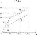
- P-F characteristics in a high depression speed range are set to have an upward-convex logarithmic functional shape, which is formed in such a way that a rate of change in tangent angle in terms of P-F characteristics decreases, as compared with P-F characteristics in a low depression speed range illustrated in FIG. 6 . Therefore, as illustrated in FIG. 7 .
- main advancement characteristics FBa corresponding to a range from an initial depression amount Sa and a position of a reaction force Fd to a maximum depression amount Sb and a position of a reaction force Fe are set to have a downward-convex exponential functional shape in which a rate of change in tangent angle is small, as compared with the main advancement characteristics FB illustrated in FIG. 4 .
- main advancement characteristics FBa are set in such a way that a rate of change in tangent angle of the main advancement characteristics FBa decreases, as the main advancement characteristics FBa approach an intermediate depression amount Sc (a reaction force Ff) which is a midpoint between an initial depression amount Sa and a maximum depression amount Sb.
- an intermediate depression amount Sc a reaction force Ff
- a degree of non-linearity may be adjusted by using an inverse number of a radius of curvature in a specific range, in place of the above-described rate of change in tangent angle.
- the muscle activity estimation unit 23 is configured in such a way as to estimate a rate of contribution of a bilateral muscle with respect to an operation of the accelerator pedal 3 on the basis of a posture state of a driver.
- a bilateral muscle has characteristics such that energy efficiency is high, and an operating speed is fast, as compared with a single articular muscle.
- a driver's driving posture is a posture in which a rate of contribution of a bilateral muscle is small in operating the accelerator pedal 3
- a ratio of activity of a bilateral muscle among skeletal muscles around an ankle joint is increased by increasing a reaction force F of the accelerator pedal 3, thereby increasing a rate of contribution with respect to muscle activity of a bilateral muscle in a driver's operation of depressing and returning the accelerator pedal 3.
- the muscle activity estimation unit 23 determines a posture state of a driver by using a seat position detected by the seat position sensor 9 as a parameter.
- the muscle activity estimation unit 23 respectively estimates that, when an addition value T+L, which is acquired by adding a seat height T and a slide amount L, is smaller than a threshold value A, a rate of contribution of a bilateral muscle becomes large; when the addition value T+L is not smaller than the threshold value A but not larger than a threshold value B (A ⁇ B), a rate of contribution of a bilateral muscle becomes intermediate; and when the addition value T+L is larger than the threshold value B, a rate of contribution of a bilateral muscle becomes small.
- threshold values A and B are acquired in advance by an experiment or the like on the basis of articular viscoelastic properties of a human.
- the muscle activity estimation unit 23 is configured to estimate whether a main working muscle of the lower limb of a human body which is an activity subject is a single articular muscle or a bilateral muscle on the basis of a traveling condition during driving, specifically, a depression speed V of the accelerator pedal 3 at a depression initial stage.
- a bilateral muscle in which an operating speed is fast and an operating force is large is suitable as a main working muscle.
- intermediate acceleration e.g., an acceleration operation for 1 to 3 sec. when a depression speed V is small, as compared with rapid acceleration
- a state (balance range) in which a single articular muscle and a bilateral muscle are well-balanced is suitable.
- slow acceleration e.g., an acceleration operation for 3 sec. or longer, when a depression speed V is small, as compared with intermediate acceleration
- a single articular muscle in which operation accuracy of an operation of depressing and returning is high is suitable as a main working muscle.
- a bilateral muscle is a main working muscle which is an activity subject
- an intermediate acceleration operation it is estimated that a single articular muscle and a bilateral muscle are to be cooperated
- a slow acceleration operation it is estimated that a single articular muscle is a main working muscle which is an activity subject.
- the muscle activity estimation unit 23 determines a driving condition by a depression speed V and an operation time of the accelerator pedal 3 detected by the depression speed sensor 5.
- the reaction force setting unit 24 is configured to correct a reaction force F in main advancement characteristics FB on the basis of a rate of contribution with respect to muscle activity of a bilateral muscle, which is estimated by the muscle activity estimation unit 23.
- the reaction force setting unit 24 respectively sets a posture correction coefficient K1 for correcting a reaction force F of main advancement characteristics FB depending on an estimated rate of contribution of a bilateral muscle.
- the posture correction coefficient K1 when a rate of contribution of a bilateral muscle is large, since the bilateral muscle sufficiently acts, the posture correction coefficient K1 is set to zero so as to maintain basic characteristics.
- the posture correction coefficient K1 is set to K1a (0 ⁇ K1a) in such a way that a reaction force F increases in order to increase the rate of contribution of the bilateral muscle.
- the posture correction coefficient K1 is set to K1b, which is a value larger than K1a, in order to further increase the rate of contribution of the bilateral muscle.
- the reaction force setting unit 24 is configured to correct a reaction force F of main advancement characteristics FB on the basis of a main working muscle, which is estimated by the muscle activity estimation unit 23.
- the reaction force setting unit 24 respectively sets a main advancement characteristic correction coefficient K2 for correcting a reaction force F of main advancement characteristics FB depending on an estimated main working muscle which is an activity subject.
- the main advancement characteristic correction coefficient K2 when a depression speed V is equal to or lower than 0, the main advancement characteristic correction coefficient K2 is set to zero so as to maintain basic characteristics.
- the main advancement characteristic correction coefficient K2 When a depression speed V corresponds to slow acceleration, the main advancement characteristic correction coefficient K2 is set to K2a (K2a ⁇ 0) in such a way that a reaction force F of main advancement characteristics FB decreases.
- the main advancement correction coefficient K2 is set to K2b (K2a ⁇ K2b ⁇ 0) in such a way that a reaction force F decreases.
- the main advancement characteristic correction coefficient K2 is set to K2c (0 ⁇ K2c) in such a way that a reaction force F increases.
- the main advancement characteristic correction coefficient K2 is set to K2d, which is a value larger than K2c, in order to further increase the reaction force F.
- the main advancement characteristic correction coefficient K2a is a coefficient for correcting a reaction force F of main advancement characteristics FB in basic characteristics to a predetermined reaction force F at which a rate of contribution of a single articular muscle is substantially equal to or larger than 60 % in order to substantially make a rate of contribution of a bilateral muscle lower than 40 %, which corresponds to a lower limit of the above-described balance range.
- the main advancement characteristic correction coefficients K2b and K2c are coefficients for correcting a reaction force F of main advancement characteristics FB in basic characteristics to a predetermined reaction force F at which a rate of contribution of a bilateral muscle is within a balance range (a range where a rate of contribution of a bilateral muscle is not smaller than 40 % but not larger than 60 %).
- the main advancement characteristic correction coefficient K2d is a coefficient for correcting a reaction force F of main advancement characteristics FB in basic characteristics to a predetermined reaction force F at which a rate of contribution of a bilateral muscle is substantially equal to or larger than 60 % in order to substantially make a rate of contribution of a bilateral muscle larger than 60 %, which corresponds to an upper limit of a balance range.
- the main advancement correction coefficients K2a to K2d may not be necessarily set on the basis of an upper limit and a lower limit of a balance range, and may be set on the basis of a design condition, as necessary.
- the reaction force setting unit 24 calculates initial characteristics (initial advancement characteristics FAa and terminal return characteristics FDa), which are acquired by correcting initial advancement characteristics FA and terminal return characteristics FD in a range smaller than an initial depression amount Sa in a direction of increasing a reaction force by a predetermined amount; and performs initial characteristic correction on the basis of the initial characteristics.
- the reaction force setting unit 24 corrects the entirety of F-S characteristics regarding main advancement characteristics FB and main return characteristics FC in an offset manner in a direction of increasing a reaction force on the basis of the following Eq. (2).
- Fx 1 + ⁇ ⁇ K 1 + ⁇ ⁇ K 2 ⁇ F
- Fx is a reaction force value after correction
- ⁇ and ⁇ are coefficients.
- the reaction force setting unit 24 corrects F-S characteristics depending on a driving condition on the basis of the following Eq. (3).
- Fx F + ⁇ ⁇ K 1 + ⁇ ⁇ K 2 ⁇ S where ⁇ and ⁇ are coefficients.
- the reaction force setting unit 24 outputs a command signal relating to a reaction force F on the basis of F-S characteristics, which are corrected by the reaction force control mechanism 11.
- reaction force control mechanism 11 is activated on the basis of F-S characteristics reflecting the reaction force Fx after correction, and the processing returns.
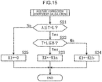
- the posture correction coefficient calculation processing step first, it is determined whether an addition value T+L, which is acquired by adding a seat height T and a slide amount L, is equal to or larger than a threshold value A (S21).
- a posture state is a state in which a rate of contribution with respect to muscle activity of a bilateral muscle is high, zero (0) is substituted into the posture correction coefficient K1 (S25), and the processing ends.
- the main advancement characteristic correction coefficient calculation processing step first, it is determined whether a depression speed V of the accelerator pedal 3 is larger than zero (a depressing operation is present) (S31).
- K2a is substituted into the main advancement characteristic correction coefficient K2 in order to increase operation accuracy in driving (S33), and the processing ends.
- K2b is substituted into the main advancement characteristic correction coefficient K2 in order to correct a state that a bilateral muscle is a main working muscle to a state within a balance range (S36), and the processing ends.
- K2c is substituted into the main advancement characteristic correction coefficient K2 in order to correct a state that a single articular muscle is dominant or a balanced state, to a state within a balance range (S37), and the processing ends.
- K2d is substituted into the main advancement characteristic correction coefficient K2 in order to increase an operating speed and increase an operating force (S38), and the processing ends.
- F-S characteristics at each operating time is specifically described on the basis of FIGS. 17 to 21 .
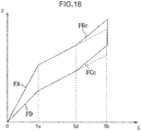
- downward-convex main advancement characteristics FB are indicated as a linear shape in parallel to main return characteristics Fc, and F-S characteristics are indicated as a model.
- main advancement characteristics FBc are corrected from a depression amount Sd in such a way that a tilt angle increases and a reaction force value increases, as compared with main advancement characteristics FB.
- Main return characteristics FCc are also corrected similarly to main advancement characteristics FBc.
- a reaction force F of main advancement characteristics FB is corrected to main advancement characteristics FBc composed of a reaction force Fx at which a rate of contribution of a bilateral muscle is equal to or larger than 60 %.
- main advancement characteristics FBd are corrected from the depression amount Sd in such a way that a tilt angle decreases and a reaction force value decreases, as compared with main advancement characteristics FB.
- Main return characteristics FCd are also corrected similarly to main advancement characteristics FBd.
- a reaction force F of main advancement characteristics FB is corrected to main advancement characteristics FBd composed of a reaction force Fx at which a rate of contribution of a bilateral muscle is smaller than 40 %.
- a tendency of decrease of a tilt angle and a reaction force value from a state of the depression amount Sd is further decreased.
- main advancement characteristics FB before correction and main advancement characteristics FBc (main advancement characteristics FBd) after correction are equal to or larger than a predetermined threshold value, since a driver may feel incongruity accompanied by a change in characteristics, the control device 1 performs correction of smoothly connecting an end of main advancement characteristics FB before correction (a range immediately before a depression amount Sd), and a beginning of main advancement characteristics FBc after correction (a range immediately after the depression amount Sd).
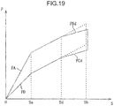
- main advancement characteristics FBe are corrected from a depression amount Sd in such a way that a tilt angle (a tangent angle) decreases, as compared with main advancement characteristics FB.
- Main return characteristics FCe are also corrected similarly to main advancement characteristics FBe. Further, in a case of a posture state in which a rate of contribution with respect to estimated muscle activity of a bilateral muscle is low, a tendency of decrease of a tilt angle from a state of the depression amount Sd is decreased.
- main advancement characteristics FBf are corrected from a depression amount Sd in such a way that a tilt angle increases, as compared with main advancement characteristics FB.
- Main return characteristics FCf are also corrected similarly to main advancement characteristics FBf.
- a posture state in which a rate of contribution with respect to estimated muscle activity of a bilateral muscle is low a tendency of increase of a tilt angle from a state of the depression amount Sd is increased.
- an upper limit and a lower limit are adjusted in such a way that a reaction force Fx after correction completion including posture correction lies within a balance range.
- main advancement characteristics FB (a value of a reaction force F) are set in such a way that until a predetermined ratio (e.g., a predetermined ratio within a range from 2.5 % to 5.0 %) with respect to a maximum depression amount of the accelerator pedal 3 reaches, a degree of increase of a value of a reaction force F relatively decreases, as a depression amount S increases; and after the predetermined ratio reaches, a degree of increase of a value of a reaction force F relatively increases, as the depression amount S increases.
- a predetermined ratio e.g., a predetermined ratio within a range from 2.5 % to 5.0
- reaction force setting unit 24 changes a value of a reaction force F exponentially functionally depending on a depression amount S of the accelerator pedal 3 in main advancement characteristics FB, it is possible to provide a driver with operation linearity, regardless of a depression speed V of the accelerator pedal 3.
- the three-dimensional map M is formed into an exponentially functional shape, it is possible to set main advancement characteristics FB of F-S characteristics on the basis of perception characteristics of a human, for example on the basis of the Weber-Fechner rule, and it is possible to securely provide a driver with operation linearity.
- the reaction force setting unit 24 decreases a degree of non-linearity of main advancement characteristics FB, as a depression speed V of the accelerator pedal 3 increases. In this configuration, it is possible to let a driver instinctively and empirically feel operation linearity, regardless of a depression speed V by strongly providing the driver with linear continuity in a low depression speed range where stimulation recognition capability is high, as compared with a high depression speed range where stimulation recognition capability is low.
- reaction force setting unit 24 decreases a rate of change in tangent angle of main advancement characteristics FB, as a depression amount S of the accelerator pedal 3 approaches an intermediate depression amount Sc, it is possible to set reaction force characteristics of the accelerator pedal suitable for articular viscoelastic properties of a human.
- control device 1 since the control device 1 includes the muscle activity estimation unit 23 for estimating whether a main working muscle of the lower limb of a human body which is an activity subject is either a single articular muscle or a bilateral muscle on the basis of a driving condition, it is possible to estimate a main working muscle which is an activity subject from a viewpoint of operation performance of a driver in an actual driving condition. Since the reaction force setting unit 24 corrects a tilt angle of main advancement characteristics FB or a reaction force F of main advancement characteristics FB on the basis of a main working muscle estimated by the muscle activity estimation unit 23, it is possible to set a skeletal muscle having a performance suitable for a driving condition, as a main working muscle as necessary, and it is possible to improve driver's operation performance of the accelerator pedal 3.
- the reaction force setting unit 24 corrects main advancement characteristics FB in a direction of decreasing a reaction force, when a main working muscle which is an activity subject is estimated to be a single articular muscle; and corrects main advancement characteristics FB in a direction of increasing a reaction force, when a main working muscle is estimated to be a bilateral muscle.
- reaction force setting unit 24 corrects the entirety of main advancement characteristics FB in an offset manner, it is possible to adjust a rate of contribution of a skeletal muscle with a simple configuration in terms of control processing.
- the vehicle control device 1 includes the depression speed sensor 5 for detecting a depression speed V of the accelerator pedal 3, and the muscle activity estimation unit 23 estimates a main working muscle on the basis of a depression speed V of the accelerator pedal 3 at a depression initial stage, the depression speed V being detected by the depression speed sensor 5, it is possible to adjust a rate of contribution of a skeletal muscle in conformity with a change in driving condition.
- the three-dimensional map M in the first embodiment is configured to decrease a degree of non-linearity of main advancement characteristics FB, as a depression speed V of the accelerator pedal 3 increases
- the three-dimensional map MA in the second embodiment is configured to increase a degree of non-linearity of main advancement characteristics FB, as a depression speed V of an accelerator pedal 3 increases.
- depression-side characteristics are constituted of initial advancement characteristics FAg (Fah) from start of depressing until an initial depression amount Sa, which corresponds to a depression start range, and main advancement characteristics FBg (FBh) from the initial depression amount Sa to a maximum depression amount Sb.
- return-side characteristics are constituted of main return characteristics FCg (FCh) from the maximum depression amount Sb to the initial depression amount Sa, and terminal return characteristics FDg (FDh) from the initial depression amount Sa until end of returning, which corresponds to a depression end range.
- the three-dimensional map MA is configured in such a way that a degree of non-linearity of main advancement characteristics FB increases, as a depression speed V of the accelerator pedal 3 increases.
- Main advancement characteristics FBh at a high depression speed is set into a downward-convex exponential functional shape in which a rate of change in tangent angle is large, as compared with main advancement characteristics FB at a low depression speed.
- FIGS. 23 , 24 , and 25 a three-dimensional map MB according to a third embodiment is described on the basis of FIGS. 23 , 24 , and 25 .
- the three-dimensional map M in the first embodiment is configured to decrease a rate of change in tangent angle of main advancement characteristics FB, as a depression amount approaches an intermediate depression amount Sc at a midpoint between an initial depression amount Sa and a maximum depression amount Sb
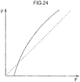
- the three-dimensional map MB in the third embodiment is configured in such a way that a depression amount is displaced from an intermediate depression amount Sc, when a rate of change in tangent angle of main advancement characteristics FBi (FBj) is smallest.
- the three-dimensional map MB includes F-S characteristics at a low depression speed, which are composed of characteristics Fa, FBi, FCi, and FD, and F-S characteristics at a high depression speed, which are composed of characteristics FAa, FBj, FCj, and FDa.
- the three-dimensional map MB is configured to decrease a degree of non-linearity of main advancement characteristics FBi, as a depression speed V of an accelerator pedal 3 increases.
- the three-dimensional map MB has characteristics such that a depression amount shifts from the intermediate depression amount Sc, when a rate of change in tangent angle decreases.
- a depression amount is set to be larger than the intermediate depression amount Sc, when a rate of change in tangent angle of main advance characteristics FBi is smallest.
- a depression amount is set to be smaller than the intermediate depression amount Sc, when a rate of change in tangent angle of main advance characteristics FBi is smallest.
- a vehicle control device includes a depression amount detection unit for detecting a depression amount of an accelerator pedal; a depression speed detection unit for detecting a depression speed of the accelerator pedal; a reaction force setting unit for setting a value of a reaction force of the accelerator pedal on the basis of detection results by the depression amount detection unit and the depression speed detection unit; and a reaction force generation unit for controlling a mechanism of the accelerator pedal on the basis of a result set by the reaction force setting unit, and generating the set reaction force.
- the reaction force setting unit sets a value of the reaction force in a manner of separating characteristics into advancement characteristics and return characteristics, the advancement characteristics being characteristics of a value of the reaction force having a correlation with respect to a depression amount of the accelerator pedal from start of depressing the accelerator pedal until end of depressing, and the return characteristics being characteristics of a value of the reaction force having a correlation with respect to a depression amount of the accelerator pedal from start of returning the accelerator pedal until end of returning.
- the reaction force setting unit sets a value of the reaction force with respect to the depression amount in such a way that, in main advancement characteristics except for both ranges corresponding to start of depressing and end of depressing among the advancement characteristics, a degree of increase of a value of the reaction force relatively decreases, as the depression amount increases until a predetermined ratio with respect to a maximum depression amount of the accelerator pedal reaches, and a degree of increase of a value of the reaction force relatively increases, as the depression amount increases after the predetermined ratio reaches.
- the reaction force setting unit sets a value of the reaction force in such a way that a value of the reaction force decreases, as the depression amount decreases in the return characteristics.
- a value of the reaction force in main advancement characteristics is set in such a way that a degree of increase of a value of the reaction force relatively decreases, as the depression amount increases until a predetermined ratio with respect to a maximum depression amount of the accelerator pedal reaches, and a degree of increase of a value of the reaction force relatively increases, as the depression amount increases after the predetermined ratio reaches. Therefore, it is possible to set reaction force characteristics (F-S characteristics) of the accelerator pedal having linear continuity regarding a reaction force perception amount.
- a vehicle control device further includes, in the above aspect, a storage unit for storing in advance a control map that defines the correlation in each of the advancement characteristics and the return characteristics.
- the reaction force setting unit sets a value of the reaction force by referring to the control map stored in the storage unit.
- the control map is defined in such a way that the correlation in the advancement characteristics has the depression amount represented along a horizontal axis, and a value of the reaction force represented along a vertical axis.
- the correlation in the advancement characteristics is set into an exponential functional shape.
- a vehicle control device is such that, in the above aspect, the reaction force setting unit decreases a degree of non-linearity of the main advancement characteristics, as a depression speed of the accelerator pedal increases.
- a vehicle control device is such that, in the above aspect, the reaction force setting unit decreases a rate of change in tangent angle of the main advancement characteristics, as a depression amount of the accelerator pedal approaches an intermediate value.
- reaction force characteristics of the accelerator pedal suitable for articular viscoelastic properties of a human.
- a vehicle control device further includes, in the above aspect, a muscle activity estimation unit for estimating whether a main working muscle of a lower limb of a human body which is an activity subject is a single articular muscle or a bilateral muscle on the basis of a driving condition.
- the reaction force setting unit corrects the correlation in the main advancement characteristics or a value of the reaction force of the main advancement characteristics on the basis of a main working muscle estimated by the muscle activity estimation unit.
- the vehicle control device since the vehicle control device includes a muscle activity estimation unit for estimating whether a main working muscle of the lower limb of a human body which is an activity subject is a single articular muscle or a bilateral muscle on the basis of a driving condition, it is possible to estimate a main working muscle which is an activity subject from a viewpoint of operation performance of a driver in an actual driving condition.
- the reaction force setting unit corrects a tilt angle of main advancement characteristics or a reaction force value of main advancement characteristics except for a depression start range and a depression end range on the basis of a main working muscle estimated by the muscle activity estimation unit, it is possible to set a skeletal muscle having performance suitable for a driving condition, as a main working muscle as necessary, and it is possible to improve driver's operation performance of the accelerator pedal.
- a vehicle control device is such that, in the above aspect, the reaction force setting unit corrects the main advancement characteristics in a direction of decreasing a reaction force, when a main working muscle which is the activity subject is estimated to be a single articular muscle, and corrects the main advancement characteristics in a direction of increasing a reaction force, when a main working muscle is estimated to be a bilateral muscle.
- a main working muscle which is an activity subject when a main working muscle which is an activity subject is estimated to be a single articular muscle, it is possible to set a rate of contribution of a single articular muscle higher than a rate of contribution of a bilateral muscle via a reaction force of the accelerator pedal; and when a main working muscle which is an activity subject is estimated to be a bilateral muscle, it is possible to set a rate of contribution of a bilateral muscle higher than a rate of contribution of a single articular muscle via a reaction force of the accelerator pedal.
- a vehicle control device is such that, in the above aspect, the reaction force setting unit performs the correction in such a way that an end of main advancement characteristics before correction and a beginning of main advancement characteristics after correction are smoothly connected.
- a vehicle control device is such that, in the above aspect, the reaction force setting unit corrects a value of the reaction force in an offset manner in an entirety of the main advancement characteristics.
- a vehicle control device is such that, in the above aspect, the muscle activity estimation unit estimates whether a main working muscle is the single articular muscle or the bilateral muscle on the basis of a depression speed of the accelerator pedal at a depression initial stage, the depression speed being detected by the depression speed detection unit.
- a vehicle control device is able to provide a driver with operation linearity, regardless of a depression speed of an accelerator pedal, and is able to let the driver sufficiently and instinctively perceive a feeling of operation.
Landscapes
- Engineering & Computer Science (AREA)
- Chemical & Material Sciences (AREA)
- Combustion & Propulsion (AREA)
- Mechanical Engineering (AREA)
- Transportation (AREA)
- General Engineering & Computer Science (AREA)
- Auxiliary Drives, Propulsion Controls, And Safety Devices (AREA)
- Control Of Throttle Valves Provided In The Intake System Or In The Exhaust System (AREA)
Abstract
Description
- The present disclosure relates to a vehicle control device capable of controlling a reaction force value of an accelerator pedal depending on muscle activity of a driver.
- Conventionally, in a case of a vehicle mounted with a drive-by-wire engine, since accelerator pedal and output control equipment such as a throttle valve and a fuel injection device are not connected to each other by a cable, a reaction value according to a depression amount is applied to a driver by an electric actuator.
- Since a depression amount of an accelerator pedal and a reaction force value are set to have a substantially proportional relationship, generally, a driver recognizes a depression amount of an accelerator pedal by a reaction force value to be applied from the accelerator pedal. Therefore, there is proposed a reaction force control device configured such that a driver's operation of depressing an accelerator pedal is guided depending on a driver's preference or a driving environment by changing a reaction force value of the accelerator pedal.
- A vehicle driving operation assist device of
Patent Literature 1 dynamically generates a driving intention sequence of a plurality of virtual drivers in a predetermined time zone in the past including a current point of time, calculates a driving operation amount sequence approximation degree representing a sequential approximation degree between a driving operation amount of a virtual driver and a driving operation amount of an actual driver for each driving intention sequence, estimates an actual driver's driving intention by comparing a plurality of driving operation amount sequence approximation degrees, and estimates an actual driver's state on the basis of the estimated driving intention. - In a case of an operation of depressing an accelerator pedal, a reaction force command value of the accelerator pedal is speedily lowered, as an elapsed time from a point of time when a driver intends to change a lane until a driver's driving intention is estimated to be changing a lane increases.
- Further, there is also proposed a technique for setting reaction force characteristics of an accelerator pedal, taking into consideration perception characteristics of a human by the present applicant.
- A vehicle accelerator pedal control device of
Patent Literature 2 includes a reaction force setting means having a three-dimensional map, which is defined by a depression amount of an accelerator pedal, a depression speed of the accelerator pedal, and a reaction force value to be applied to a driver; and a depression speed detection means for detecting a depression speed of the accelerator pedal, wherein the reaction force setting means sets reaction force characteristics in such a way that a reaction force value of the accelerator pedal decreases, when a depression speed is high, as compared with a case where a depression speed is low. - Thus, it is possible to set reaction force characteristics suitable for a driving environment or a driving intention, while alleviating burden and incongruity of a driver.
- A driver's operation of depressing and returning an accelerator pedal may be regarded as plantar flexion motion and dorsiflexion motion of an ankle joint in terms of muscle activity.
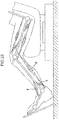
- As illustrated in
FIG. 26 , an operation of an accelerator pedal by an ankle joint mainly involves an anterior tibialis muscle t, a soleus muscle s, and a gastrocnemius muscle g. - The anterior tibialis muscle t is a single articular muscle (one articular muscle) which performs dorsiflexion motion of an ankle joint, and the soleus muscle s is a single articular muscle which performs plantar flexion motion of an ankle joint. The gastrocnemius muscle g is a bilateral muscle which performs plantar flexion motion of an ankle joint and performs flexion motion of a knee joint. Among these skeletal muscles, a single articular muscle depends on a mechanical force ratio, and has a resistance to weight of raising a body against a gravitational force. Further, a bilateral muscle suppresses mechanical energy consumption, controls a direction of an external force, and has so-called propulsion capability of propelling a body in a specific direction.
- Since a skeletal muscle has viscoelastic properties as mechanical properties, it is known that the skeletal muscle can be expressed by a two-element model constituted of a series elastic element and a contraction element; an elastic modulus of a series elastic element increases, as a muscle tension increases; there is a hyperbolic relationship between a load and a speed of a contraction element: and stiffness of the entirety of muscle has a linear relationship with respect to muscle activity.
-
- Patent Literature 1: Japanese Patent No.
5293784 - Patent Literature 2: Japanese Unexamined Patent Application Publication No.
2016-000581 - The accelerator pedal control device of
Patent Literature 1 can determine a driver's driving intention by using a depression speed of an accelerator pedal as a parameter, and set reaction force characteristics suitable for the driving intention. - However, in the technique of
Patent Literature 2, although it is possible to acquire a reaction force value of an accelerator pedal suitable for a driver's driving intention, there may occur a discrepancy between an operation amount (a physical reaction force value to be applied to a driver) with which a driver actually operates an accelerator pedal, and a reaction force perception amount which the driver instinctively feels from the accelerator pedal. - Since an amount of analyzing and processing information by a human brain increases in high speed motion, as compared with a case of low speed motion, recognition capability with respect to stimuli such as a reaction force is high when an operating speed is low in terms of perception characteristics of a human. Further, since an amount of instantaneous muscle activity increases in high speed motion, as compared with a case of low speed motion, and sensitivity to stimuli improves, discrimination capability with respect to stimuli such as a reaction force improves, as an operating speed increases in terms of perception characteristics of a human.
- Therefore, even when a correlation (hereinafter, referred to as F-S characteristics) between a reaction force value of an accelerator pedal suitable for a driver, and a depression amount is set in a specific depression speed in driving a vehicle, in a case where a driving condition changes, and a depression speed changes, F-S characteristics suitable for a driver may not be necessarily acquired.
- Specifically, since none of the patent literatures studies linear continuity of a reaction force perception amount relating to an operation of an accelerator pedal, namely, securing operation linearity regardless of a depression speed, a driver may not sufficiently and instinctively acquire a feeling of operating an accelerator pedal.
- An object of the present disclosure is to provide a vehicle control device and the like, which let a driver sufficiently and instinctively perceive a feeling of operating an accelerator pedal, regardless of a depression speed of the accelerator pedal.
- A vehicle control device according to an aspect of the present disclosure includes a depression amount detection unit for detecting a depression amount of an accelerator pedal; a depression speed detection unit for detecting a depression speed of the accelerator pedal; a reaction force setting unit for setting a value of a reaction force of the accelerator pedal on the basis of detection results by the depression amount detection unit and the depression speed detection unit; and a reaction force generation unit for controlling a mechanism of the accelerator pedal on the basis of a result set by the reaction force setting unit and generating the set reaction force. The reaction force setting unit sets a value of the reaction force in a manner of separating characteristics into advancement characteristics and return characteristics, the advancement characteristics being characteristics of a value of the reaction force having a correlation with respect to a depression amount of the accelerator pedal from start of depressing the accelerator pedal until end of depressing, and the return characteristics being characteristics of a value of the reaction force having a correlation with respect to a depression amount of the accelerator pedal from start of returning the accelerator pedal until end of returning. The reaction force setting unit sets a value of the reaction force with respect to the depression amount in such a way that, in main advancement characteristics except for both ranges corresponding to start of depressing and end of depressing among the advancement characteristics, a degree of increase of a value of the reaction force relatively decreases, as the depression amount increases until a predetermined ratio with respect to a maximum depression amount of the accelerator pedal reaches, and a degree of increase of a value of the reaction force relatively increases, as the depression amount increases after the predetermined ratio reaches. The reaction force setting unit sets a value of the reaction force in such a way that a value of the reaction force decreases, as the depression amount decreases in the return characteristics.
-
-
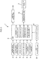
FIG. 1 is a block diagram of a vehicle control device according to a first embodiment. -
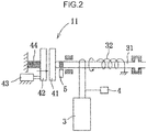
FIG. 2 is a schematic diagram of an accelerator pedal and a reaction force control mechanism. -
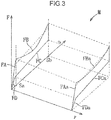
FIG. 3 is a diagram illustrating a three-dimensional map. -
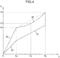
FIG. 4 is a diagram describing F-S characteristics of a three-dimensional map, and illustrates a graph of F-S characteristics at a low depression speed. -
FIG. 5 is a diagram describing F-S characteristics of a three-dimensional map, and illustrates a graph of F-S characteristics at a high depression speed. -
FIG. 6 is a diagram describing P-F characteristics, and illustrates a graph of P-F characteristics at a low depression speed. -
FIG. 7 is a diagram describing P-F characteristics, and illustrates a graph of P-F characteristics at a high depression speed. -
FIG. 8 is a diagram describing a relationship between a knee angle of a driver and a height position of a seat, and illustrates a state that a seat is set to a high position. -
FIG. 9 is a diagram describing a relationship between a knee angle of a driver and a height position of a seat, and illustrates a state that a seat is set to an intermediate position. -
FIG. 10 is a diagram describing a relationship between a knee angle of a driver and a height position of a seat, and illustrates a state that a seat is set to a low position. -
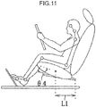
FIG. 11 is a diagram describing a relationship between a knee angle of a driver and a slide position of a seat, and illustrates a state that a seat is set to a front position. -
FIG. 12 is a diagram describing a relationship between a knee angle of a driver and a slide position of a seat, and illustrates a state that a seat is set to an intermediate position. -
FIG. 13 is a diagram describing a relationship between a knee angle of a driver and a slide position of a seat, and illustrates a state that a seat is set to a rear position. -
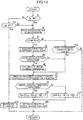
FIG. 14 is a flowchart illustrating a processing procedure of a control device. -
FIG. 15 is a flowchart illustrating a processing procedure of posture correction coefficient calculation. -
FIG. 16 is a flowchart illustrating a processing procedure of main advancement characteristic correction coefficient calculation. -
FIG. 17 is a graph of F-S characteristics when a vehicle is started with a rapid acceleration operation. -
FIG. 18 is a graph of F-S characteristics when a vehicle is operated with rapid acceleration. -
FIG. 19 is a graph of F-S characteristics when a vehicle is operated with slow acceleration. -
FIG. 20 is a graph of F-S characteristics when a main working muscle for a forward operation (a depressing operation) is a bilateral muscle, and when a vehicle is operated with intermediate acceleration. -
FIG. 21 is a graph of F-S characteristics when a main working muscle for a forward operation (a depressing operation) is a single articular muscle, and when a vehicle is operated with intermediate acceleration. -
FIG. 22 is a diagram illustrating a three-dimensional map according to a second embodiment. -
FIG. 23 is a diagram illustrating a three-dimensional map according to a third embodiment. -
FIG. 24 is a graph describing P-F characteristics at a low depression speed. -
FIG. 25 is a graph describing P-F characteristics at a high depression speed. -
FIG. 26 is an explanatory diagram of skeletal muscles when an accelerator pedal is operated. - In the following, embodiments are described in detail on the basis of drawings.
- The following description is an example in which a configuration of the present disclosure is applied to a vehicle control device. The following description does not limit the present disclosure, an application thereof, or a use thereof.
- In the following, a first embodiment is described on the basis of
FIGS. 1 to 21 . - A
vehicle control device 1 is configured to provide a driver with operation linearity regardless of a depression speed by controlling a reaction force value of anaccelerator pedal 3 depending on muscle activity of the driver. - As illustrated in
FIG. 1 , thecontrol device 1 includes an electronic control unit (ECU) 2. TheECU 2 is an electronic control unit constituted of a CPU, an ROM, an RAM, and the like. TheECU 2 loads an application program stored in an ROM into an RAM, and performs various calculation processing by causing a CPU to execute the application program. - The
ECU 2 is electrically connected to adepression amount sensor 4 for detecting an operation amount S (hereinafter, referred to as a depression amount) of depressing or returning theaccelerator pedal 3, a depression speed sensor 5 (a depression speed detection unit) for detecting a depression speed V of theaccelerator pedal 3, aspeed sensor 6 for detecting a traveling speed of a vehicle, ayaw rate sensor 7 for detecting a yaw rate acting on a vehicle, anacceleration sensor 8 for detecting an acceleration of a traveling vehicle, a seat position sensor 9 (a seat position detection unit) for detecting a seat position of a driver, avehicle driving unit 10, a reaction force control mechanism 11 (a reaction force generation unit), anavigation system 12, and the like. - As illustrated in
FIG. 2 , theaccelerator pedal 3 is pivotally held with respect to a vehicle body. A driver's intention of increasing or decreasing an engine output is input to theaccelerator pedal 3 by a driver's depressing operation. - The
depression amount sensor 4 is provided on theaccelerator pedal 3 or arotating shaft 31, and detects a depression stroke of theaccelerator pedal 3, namely, a so-called depression amount S from a return amount of theaccelerator pedal 3 or therotating shaft 31. The depression amount S of theaccelerator pedal 3 detected by thedepression amount sensor 4 is output to theECU 2. Note that it is configured such that, when a depressing force by a driver's depressing operation does not act, theaccelerator pedal 3 is urged to return to an initial position where the depression amount S is zero by areturn spring 32, which is connected to theaccelerator pedal 3. - The
depression speed sensor 5 is provided on therotating shaft 31 of theaccelerator pedal 3, and detects a depression speed V of theaccelerator pedal 3 from a rotational speed of therotating shaft 31. A depression speed V of theaccelerator pedal 3 detected by thedepression speed sensor 5 is output to theECU 2. - The
seat position sensor 9 detects a distance in an up-down (vertical) direction from a center position of a seat cushion to a floor panel, as a seat height T (T1, T2, T3) (seeFIGS. 8 to 10 ). Further, theseat position sensor 9 detects a distance in a front-rear (horizontal) direction from a rear end position of a slide rail to the center position of the seat cushion, as a slide amount L (L1, L2, L3) (seeFIGS. 11 to 13 ). A seat height T and a slide amount L detected by theseat position sensor 9 are output to theECU 2. - Each of the
speed sensor 6, theyaw rate sensor 7, and theacceleration sensor 8 outputs a detection result thereof to theECU 2. - The
vehicle driving unit 10 is a driving mechanism and a steering mechanism for controlling driving of a vehicle. - The
vehicle driving unit 10 is constituted of an engine control unit, a steering actuator, a brake actuator, a shift actuator (each of which is not illustrated), and the like. - The
vehicle driving unit 10 controls driving of a vehicle on the basis of an output signal from theECU 2. - As illustrated in
FIG. 2 , the reactionforce control mechanism 11 includes afirst friction member 41, asecond friction member 42, anelectromagnetic actuator 43, and the like. - The
first friction member 41 is fixed to one end of therotating shaft 31, and thesecond friction member 42 is disposed to face thefirst friction member 41. Thesecond friction member 42 is non-rotatably held with respect to a retainingshaft 44 which axially extends along the rotatingshaft 31, and is axially movable relative to the retainingshaft 44. - The
actuator 43 is configured to change a relative positional relationship of the first andsecond friction members - The
navigation system 12 is a system for navigating a route of a vehicle. - As illustrated in
FIG. 1 , thenavigation system 12 is electrically connected to aGPS receiving unit 13 for detecting a current position of a vehicle. TheGPS receiving unit 13 detects a current position of a vehicle by receiving a signal from a plurality of GPS satellites. - Further, the
navigation system 12 includes a map database for storing road map data, and a traffic rule database for storing traffic rule data. - The
navigation system 12 navigates a driver to a destination by using current position data of a vehicle by theGPS receiving unit 13, road map data of a map database, and traffic rule data of a traffic rule database. - Thus, the
navigation system 12 outputs, to theECU 2, current position data of a vehicle, road map data, and traffic rule data. - Next, the
ECU 2 is described. - As illustrated in
FIG. 1 , theECU 2 includes a drivingcontrol unit 21, astorage unit 22, a muscleactivity estimation unit 23, a reactionforce setting unit 24, and the like. - The driving
control unit 21 is configured such that an output of an engine is controlled, on the basis of a depression amount S of theaccelerator pedal 3, and a vehicle speed detected by thespeed sensor 6; and a gear ratio of a transmission is selectable on the basis of a vehicle traveling state and a driving state of the engine. - An output of an engine decelerated by a transmission is transmitted to driving wheels via a drive shaft (not illustrated).
- The
storage unit 22 stores in advance a three-dimensional map M, which is defined by a depression amount S and a depression speed V of theaccelerator pedal 3 by a driver, and a reaction force F corresponding to a physical reaction force value acting on the driver from theaccelerator pedal 3. - As illustrated in
FIG. 3 , the three-dimensional map M is sterically formed by three axes, namely, an S-axis (a vertical axis) corresponding to a depression amount S (Sa to Sd) of theaccelerator pedal 3, a V-axis (a horizontal axis) corresponding to a depression speed V of theaccelerator pedal 3, and an F-axis (a height axis) corresponding to a reaction force F (Fa to Ff) to be applied to a driver via theaccelerator pedal 3. - Basic characteristics of the three-dimensional map M are formed by using a standard driver as a target, and are set on the basis of a premise that, in a driver's predetermined operation of the
accelerator pedal 3, namely, in an operation of depressing and returning (plantar flexion motion and dorsiflexion motion of an ankle joint), a bilateral muscle (e.g., a gastrocnemius muscle) and a single articular muscle (e.g. an anterior tibialis muscle or a soleus muscle) are operated within a predetermined balance range (e.g. a range where a rate of contribution of a bilateral muscle is not smaller than 40 % but not larger than 60 %). Note that a numerical value of a balance range is acquired in advance by an experiment or the like. - Regarding correlation characteristics (hereinafter, referred to as F-S characteristics) between a reaction force F and a depression amount S in a three-dimensional map M, depression-side characteristics are constituted of initial advancement characteristics FA (FAa) from start of depression until an initial depression amount Sa, which corresponds to a depression start range, and main advancement characteristics FB (FBa to FBf) from the initial depression amount Sa to a maximum depression amount Sb. Further, return-side characteristics are constituted of main return characteristics FC (FCa to FCf) from the maximum depression amount Sb to the initial depression amount Sa, and terminal return characteristics FD (FDa) from the initial depression amount Sa until end of returning, which corresponds to a depression end range.
- Note that, unless otherwise specifically mentioned, for convenience, the following description is made with use of a depression amount S, a reaction force F, and characteristics FA, FB, FC, and FD, while using a depression amount S (Sa to Sd), a reaction force F (Fa to Ff), characteristics FA (FAa), FB (FBa to FBf), FC (FCa to FCf), and FD (FDa) as representative symbols, respectively.
- Further, in the foregoing, an "initial depression amount Sa" is settable to a ratio within a range from 2.5 % to 5.0 % with respect to a maximum depression amount of the
accelerator pedal 3, for example. - As illustrated in
FIGS. 3 and4 , initial advancement characteristics FA are set in such a way as to linearly increase, as a depression amount S increases; and main advancement characteristics FB are set in such a way as to increase and protrude downward, as the depression amount S increases. In other words, in main advancement characteristics FB, a relationship between a depression amount S and a reaction force F is set in such a way that a degree of increase of a value of a reaction force F relatively decreases in a zone until a predetermined depression amount S, and a degree of increase of a value of a reaction force F relatively increases in a zone over the predetermined depression amount S. - Note that, in the foregoing, a "predetermined depression amount S" is settable to a ratio within a range from 40 % to 60 % (in the present embodiment, 50 % as an example) with respect to a total depression amount in main advancement characteristics FB, for example.
- Main return characteristics FC are set in such a way as to linearly decrease, as a depression amount S decreases. Terminal return characteristics FD are set in such a way as to linearly decrease with a tendency of decrease larger than main return characteristics FC.
- Since a reaction force perception amount P (a sensory strength) perceived as a feeling of a driver is proportional to a logarithm of a reaction force F (a stimulation strength) (the Weber-Fechner rule), it is possible to acquire a value or a tendency of a reaction force F on the basis of the reaction force perception amount P having a predetermined tendency by the following Equation (1).

- As illustrated in
FIG. 6 , it is possible to allow a driver to perceive (feel) a reaction force perception amount P having linear continuity, which is illustrated by the broken line, by setting correlation characteristics (hereinafter, referred to as P-F characteristics) between the reaction force perception amount P and the reaction force F to have an upward-convex logarithmic functional shape. Therefore, as illustrated inFIG. 4 , regarding F-S characteristics at a low depression speed, main advancement characteristics FB corresponding to a range from an initial depression amount Sa and a position of a reaction force Fa to a maximum depression amount Sb and a position of a reaction force Fb are set to have a downward-convex exponential functional shape, which is acquired by inverting the upward-convex logarithmic functional shape illustrated inFIG. 6 . - The main advancement characteristics FB are set in such a way that a rate of change in tangent angle of the main advancement characteristics FB decreases, as the main advancement characteristics FB approach an intermediate depression amount Sc (a reaction force Fc) which is a midpoint between an initial depression amount Sa and a maximum depression amount Sb.
- Further, the three-dimensional map M is set in such a way that a degree of non-linearity of main advancement characteristics FB decreases, as a depression speed V of the
accelerator pedal 3 increases. - As illustrated in
FIG. 7 , P-F characteristics in a high depression speed range are set to have an upward-convex logarithmic functional shape, which is formed in such a way that a rate of change in tangent angle in terms of P-F characteristics decreases, as compared with P-F characteristics in a low depression speed range illustrated inFIG. 6 . Therefore, as illustrated inFIG. 5 , in F-S characteristics at a high depression speed, main advancement characteristics FBa corresponding to a range from an initial depression amount Sa and a position of a reaction force Fd to a maximum depression amount Sb and a position of a reaction force Fe are set to have a downward-convex exponential functional shape in which a rate of change in tangent angle is small, as compared with the main advancement characteristics FB illustrated inFIG. 4 . - This is for the purpose of letting a driver strongly perceive linear continuity in a low depression speed range where stimulation recognition capability is high, as compared with a high depression speed range where stimulation recognition capability is low, thereby letting the driver instinctively and empirically perceive operation linearity regardless of a depression speed V.
- Further, similarly to main advancement characteristics FB, main advancement characteristics FBa are set in such a way that a rate of change in tangent angle of the main advancement characteristics FBa decreases, as the main advancement characteristics FBa approach an intermediate depression amount Sc (a reaction force Ff) which is a midpoint between an initial depression amount Sa and a maximum depression amount Sb.
- Note that a degree of non-linearity may be adjusted by using an inverse number of a radius of curvature in a specific range, in place of the above-described rate of change in tangent angle.
- Next, the muscle
activity estimation unit 23 is described. - The muscle
activity estimation unit 23 is configured in such a way as to estimate a rate of contribution of a bilateral muscle with respect to an operation of theaccelerator pedal 3 on the basis of a posture state of a driver. - A bilateral muscle has characteristics such that energy efficiency is high, and an operating speed is fast, as compared with a single articular muscle. In view of the above, when a driver's driving posture is a posture in which a rate of contribution of a bilateral muscle is small in operating the
accelerator pedal 3, a ratio of activity of a bilateral muscle among skeletal muscles around an ankle joint is increased by increasing a reaction force F of theaccelerator pedal 3, thereby increasing a rate of contribution with respect to muscle activity of a bilateral muscle in a driver's operation of depressing and returning theaccelerator pedal 3. - The muscle
activity estimation unit 23 determines a posture state of a driver by using a seat position detected by theseat position sensor 9 as a parameter. - As illustrated in
FIG. 8 , when a seat height T adjusted by a driver is T1, a driver's knee is bent, and a knee angle θ1 decreases. Therefore, a rate of contribution of a bilateral muscle in bending motion and dorsiflexion motion of an ankle joint decreases (a rate of contribution of a single articular muscle increases). - As illustrated in
FIG. 9 , when a seat height T adjusted by a driver is T2 (T2<T1), since a knee angle θ2 of the driver is larger than the knee angle θ1, a rate of contribution of a bilateral muscle at the knee angle θ2 increases, as compared with a rate of contribution of a bilateral muscle at the knee angle θ1. - As illustrated in
FIG. 10 , when a seat height T adjusted by a driver is T3 (T3<T2), since a knee angle θ3 of the driver is larger than the knee angle θ2, a rate of contribution of a bilateral muscle at the knee angle θ3 increases, as compared with a rate of contribution of a bilateral muscle at the knee angle θ2. - Thus, it is estimated that a rate of contribution of a bilateral muscle increases, as a seat height T decreases.
- As illustrated in
FIG. 11 , when a slide amount L adjusted by a driver is L1 (when a driver is a woman or a person having a small physical size), since a knee angle θ4 of the driver decreases, a rate of contribution of a bilateral muscle in bending motion and dorsiflexion motion of an angle joint decreases. - As illustrated in
FIG. 12 , when a slide amount L adjusted by a driver is L2 (when a driver has a standard physical size) (L2<L1), since a knee angle θ5 is larger than the knee angle θ4, a rate of contribution of a bilateral muscle at the knee angle θ5 increases, as compared with a rate of contribution of a bilateral muscle at the knee angle θ4. - As illustrated in
FIG. 13 , when a slide amount L adjusted by a driver is L3 (when a driver has a large physical size) (L3<L2), since a knee angle θ6 is larger than the knee angle θ5, a rate of contribution of a bilateral muscle at the knee angle θ6 increases, as compared with a rate of contribution of a bilateral muscle at the knee angle θ5. - Thus, it is estimated that a rate of contribution of a bilateral muscle increases, as a slide amount L decreases.
- The muscle
activity estimation unit 23 respectively estimates that, when an addition value T+L, which is acquired by adding a seat height T and a slide amount L, is smaller than a threshold value A, a rate of contribution of a bilateral muscle becomes large; when the addition value T+L is not smaller than the threshold value A but not larger than a threshold value B (A<B), a rate of contribution of a bilateral muscle becomes intermediate; and when the addition value T+L is larger than the threshold value B, a rate of contribution of a bilateral muscle becomes small. - Note that the threshold values A and B are acquired in advance by an experiment or the like on the basis of articular viscoelastic properties of a human.
- Further, the muscle
activity estimation unit 23 is configured to estimate whether a main working muscle of the lower limb of a human body which is an activity subject is a single articular muscle or a bilateral muscle on the basis of a traveling condition during driving, specifically, a depression speed V of theaccelerator pedal 3 at a depression initial stage. - At rapid acceleration (e.g., an acceleration operation for less than 1 sec. when a depression speed V is large), a bilateral muscle in which an operating speed is fast and an operating force is large is suitable as a main working muscle. At intermediate acceleration (e.g., an acceleration operation for 1 to 3 sec. when a depression speed V is small, as compared with rapid acceleration), a state (balance range) in which a single articular muscle and a bilateral muscle are well-balanced is suitable. At slow acceleration (e.g., an acceleration operation for 3 sec. or longer, when a depression speed V is small, as compared with intermediate acceleration), a single articular muscle in which operation accuracy of an operation of depressing and returning is high is suitable as a main working muscle. In view of the above, when a rapid acceleration operation is detected in operating the
accelerator pedal 3, it is estimated that a bilateral muscle is a main working muscle which is an activity subject; when an intermediate acceleration operation is detected, it is estimated that a single articular muscle and a bilateral muscle are to be cooperated; and when a slow acceleration operation is detected, it is estimated that a single articular muscle is a main working muscle which is an activity subject. - The muscle
activity estimation unit 23 determines a driving condition by a depression speed V and an operation time of theaccelerator pedal 3 detected by thedepression speed sensor 5. - Next, the reaction
force setting unit 24 is described. - The reaction
force setting unit 24 is configured to correct a reaction force F in main advancement characteristics FB on the basis of a rate of contribution with respect to muscle activity of a bilateral muscle, which is estimated by the muscleactivity estimation unit 23. - The reaction
force setting unit 24 respectively sets a posture correction coefficient K1 for correcting a reaction force F of main advancement characteristics FB depending on an estimated rate of contribution of a bilateral muscle. - In the present embodiment, when a rate of contribution of a bilateral muscle is large, since the bilateral muscle sufficiently acts, the posture correction coefficient K1 is set to zero so as to maintain basic characteristics. When a rate of contribution of a bilateral muscle is intermediate, the posture correction coefficient K1 is set to K1a (0<K1a) in such a way that a reaction force F increases in order to increase the rate of contribution of the bilateral muscle. When a rate of contribution of a bilateral muscle is small, the posture correction coefficient K1 is set to K1b, which is a value larger than K1a, in order to further increase the rate of contribution of the bilateral muscle.
- The reaction
force setting unit 24 is configured to correct a reaction force F of main advancement characteristics FB on the basis of a main working muscle, which is estimated by the muscleactivity estimation unit 23. - The reaction
force setting unit 24 respectively sets a main advancement characteristic correction coefficient K2 for correcting a reaction force F of main advancement characteristics FB depending on an estimated main working muscle which is an activity subject. - In the present embodiment, when a depression speed V is equal to or lower than 0, the main advancement characteristic correction coefficient K2 is set to zero so as to maintain basic characteristics. When a depression speed V corresponds to slow acceleration, the main advancement characteristic correction coefficient K2 is set to K2a (K2a<0) in such a way that a reaction force F of main advancement characteristics FB decreases. When a main working muscle for a forward operation (a depressing operation) is a bilateral muscle, and a depression speed V corresponds to intermediate acceleration, the main advancement correction coefficient K2 is set to K2b (K2a<K2b<0) in such a way that a reaction force F decreases. When a main working muscle for a forward operation (a depressing operation) is a single articular muscle, and a depression speed V corresponds to intermediate acceleration, the main advancement characteristic correction coefficient K2 is set to K2c (0<K2c) in such a way that a reaction force F increases. When a depression speed V corresponds to rapid acceleration, the main advancement characteristic correction coefficient K2 is set to K2d, which is a value larger than K2c, in order to further increase the reaction force F.
- The main advancement characteristic correction coefficient K2a is a coefficient for correcting a reaction force F of main advancement characteristics FB in basic characteristics to a predetermined reaction force F at which a rate of contribution of a single articular muscle is substantially equal to or larger than 60 % in order to substantially make a rate of contribution of a bilateral muscle lower than 40 %, which corresponds to a lower limit of the above-described balance range. The main advancement characteristic correction coefficients K2b and K2c are coefficients for correcting a reaction force F of main advancement characteristics FB in basic characteristics to a predetermined reaction force F at which a rate of contribution of a bilateral muscle is within a balance range (a range where a rate of contribution of a bilateral muscle is not smaller than 40 % but not larger than 60 %). The main advancement characteristic correction coefficient K2d is a coefficient for correcting a reaction force F of main advancement characteristics FB in basic characteristics to a predetermined reaction force F at which a rate of contribution of a bilateral muscle is substantially equal to or larger than 60 % in order to substantially make a rate of contribution of a bilateral muscle larger than 60 %, which corresponds to an upper limit of a balance range. The main advancement correction coefficients K2a to K2d may not be necessarily set on the basis of an upper limit and a lower limit of a balance range, and may be set on the basis of a design condition, as necessary.
- Further, when a vehicle is started with a rapid acceleration operation, the reaction
force setting unit 24 calculates initial characteristics (initial advancement characteristics FAa and terminal return characteristics FDa), which are acquired by correcting initial advancement characteristics FA and terminal return characteristics FD in a range smaller than an initial depression amount Sa in a direction of increasing a reaction force by a predetermined amount; and performs initial characteristic correction on the basis of the initial characteristics. - When initial characteristic correction is performed, the reaction
force setting unit 24 corrects the entirety of F-S characteristics regarding main advancement characteristics FB and main return characteristics FC in an offset manner in a direction of increasing a reaction force on the basis of the following Eq. (2).
- When initial advancement characteristic correction is not performed (except that when a vehicle is started with rapid acceleration), the reaction
force setting unit 24 corrects F-S characteristics depending on a driving condition on the basis of the following Eq. (3).
- The reaction
force setting unit 24 outputs a command signal relating to a reaction force F on the basis of F-S characteristics, which are corrected by the reactionforce control mechanism 11. - Next, a control processing procedure of the
control device 1 is described on the basis of flowcharts ofFIGS. 14 to 16 . - Note that Si (i=1, 2, ...) denotes a step for each processing.
- As illustrated in the flowchart of
FIG. 14 , first, in S1, it is determined whether an ignition switch (ig) is turned on. - When the ignition switch is turned on as a determination result of S1, information input from the
various sensors 4 to 9 and thenavigation system 12 is read (S2), and the processing proceeds to S3. - In S3, it is determined whether a vehicle is started.
- When the vehicle is started as a determination result of S3, a posture correction coefficient K1 is calculated (S4), and the processing proceeds to S5.
- In S5, it is determined whether the driver starts the vehicle by a rapid acceleration operation.
- When the driver performs a rapid acceleration operation as a determination result of S5, initial characteristics regarding initial advancement characteristics FA and terminal return characteristics FD are calculated (S6), and the processing proceeds to S7.
- In S7, a main advancement characteristic correction coefficient K2 is calculated, and the processing proceeds to S8.
- In S8, presence or absence of initial characteristic correction is determined.
- When initial characteristics are corrected as a determination result of S8, a reaction force Fx after correction is calculated on the basis of Eq. (2) (S9), and the processing proceeds to S10.
- In S10, the reaction
force control mechanism 11 is activated on the basis of F-S characteristics reflecting the reaction force Fx after correction, and the processing returns. - When initial characteristics are not corrected as a determination result of S8, a reaction force Fx after correction is calculated on the basis of Eq. (3) (S11), and the processing proceeds to S10.
- When the driver does not perform a rapid acceleration operation as a determination result of S5, the processing proceeds to S7.
- When the vehicle is not started as a determination result of S3, the processing proceeds to S12, and it is determined whether the vehicle is traveling in a range corresponding to main advancement characteristics FB.
- When the vehicle is traveling in a range corresponding to main advancement characteristics FB as a determination result of S12, the processing proceeds to S7. When the vehicle is not traveling in a range corresponding to main advancement characteristics FB as a determination result of S12, the processing returns.
- Next, a posture correction coefficient calculation processing of S4 is described.
- As illustrated in the flowchart of
FIG. 15 , in the posture correction coefficient calculation processing step, first, it is determined whether an addition value T+L, which is acquired by adding a seat height T and a slide amount L, is equal to or larger than a threshold value A (S21). - When the addition value T+L is equal to or larger than the threshold value A as a determination result of S21, the processing proceeds to S22, and it is determined whether the addition value T+L is equal to or smaller than a threshold value B.
- When the addition value T+L is equal to or smaller than the threshold value B as a determination result of S22, since a posture state is a state in which a rate of contribution with respect to muscle activity of a bilateral muscle is low, K1a is substituted into the posture correction coefficient K1 (S23), and the processing ends.
- When the addition value T+L is larger than the threshold value B as a determination result of S22, since a posture state is a state in which a rate of contribution with respect to muscle activity of a bilateral muscle is further low, K1b is substituted into the posture correction coefficient K1 (S24), and the processing ends.
- When the addition value T+L is smaller than the threshold value A as a determination result of S21, since a posture state is a state in which a rate of contribution with respect to muscle activity of a bilateral muscle is high, zero (0) is substituted into the posture correction coefficient K1 (S25), and the processing ends.
- Next, a main advancement characteristic correction coefficient calculation processing step of S7 is described.
- As illustrated in the flowchart of
FIG. 16 , in the main advancement characteristic correction coefficient calculation processing step, first, it is determined whether a depression speed V of theaccelerator pedal 3 is larger than zero (a depressing operation is present) (S31). - When the depression speed V of the
accelerator pedal 3 is larger than zero as a determination result of S31, the processing proceeds to S32, and it is determined whether slow acceleration is performed. - When slow acceleration is performed as a determination result of S32, K2a is substituted into the main advancement characteristic correction coefficient K2 in order to increase operation accuracy in driving (S33), and the processing ends.
- When slow acceleration is not performed as a determination result of S32, the processing proceeds to S34, and it is determined whether intermediate acceleration is performed.
- When intermediate acceleration is performed as a determination result of S34, the processing proceeds to S35, and it is determined whether a main working muscle for a forward operation (a depressing operation) is a bilateral muscle.
- When a main working muscle for a forward operation (a depressing operation) is a bilateral muscle as a determination result of S35, K2b is substituted into the main advancement characteristic correction coefficient K2 in order to correct a state that a bilateral muscle is a main working muscle to a state within a balance range (S36), and the processing ends.
- When a main working muscle for a forward operation (a depressing operation) is not a bilateral muscle as a determination result of S35, K2c is substituted into the main advancement characteristic correction coefficient K2 in order to correct a state that a single articular muscle is dominant or a balanced state, to a state within a balance range (S37), and the processing ends.
- When intermediate acceleration is not performed as a determination result of S34, since rapid acceleration is performed, K2d is substituted into the main advancement characteristic correction coefficient K2 in order to increase an operating speed and increase an operating force (S38), and the processing ends.
- When a depression speed V of the
accelerator pedal 3 is equal to or lower than zero as a determination result of S31, zero is substituted into the main advancement characteristic correction coefficient K2 (S39), and the processing ends. - F-S characteristics at each operating time is specifically described on the basis of
FIGS. 17 to 21 . - Note that, in
FIGS. 17 to 21 , in order to facilitate understanding, for convenience, downward-convex main advancement characteristics FB are indicated as a linear shape in parallel to main return characteristics Fc, and F-S characteristics are indicated as a model. - As illustrated in
FIG. 17 , when a vehicle is started with a rapid acceleration operation, since a main working muscle to be acted is estimated to be a bilateral muscle, initial advancement characteristics FA and terminal return characteristics FD are respectively corrected to initial advancement characteristics FAb and terminal return characteristics FDb, which are shifted upward; and main advancement characteristics FB and main return characteristics FC are also corrected to main advancement characteristics FBb and main return characteristics FCb, which are shifted upward. Thus, by shifting the entirety of F-S characteristics before correction upward in an offset manner (or a shifting manner), a reaction force F of main advancement characteristics FB is corrected to main advancement characteristics FBb composed of a reaction force Fx at which a rate of contribution of a bilateral muscle is equal to or larger than 60 %. Further, in a case of a posture state in which a rate of contribution with respect to estimated muscle activity of a bilateral muscle is low, the offset amount is further increased. - As illustrated in
FIG. 18 , when a rapid acceleration operation is performed from a state of a depression amount Sd (e.g., a vehicle merges into a main lane on a highway or cuts in), since a main working muscle to be acted is estimated to be a bilateral muscle, main advancement characteristics FBc are corrected from a depression amount Sd in such a way that a tilt angle increases and a reaction force value increases, as compared with main advancement characteristics FB. Main return characteristics FCc are also corrected similarly to main advancement characteristics FBc. Thus, a reaction force F of main advancement characteristics FB is corrected to main advancement characteristics FBc composed of a reaction force Fx at which a rate of contribution of a bilateral muscle is equal to or larger than 60 %. Further, in a case of a posture state in which a rate of contribution with respect to estimated muscle activity of a bilateral muscle is low, a tendency of increase of a tilt angle and a reaction force value from a point of time corresponding to the depression amount Sd is further increased. - As illustrated in
FIG. 19 , when a slow acceleration operation is performed from a state of a depression amount Sd (e.g., when a vehicle is traveling on a plain road), since a main working muscle to be acted is estimated to a single articular muscle, main advancement characteristics FBd are corrected from the depression amount Sd in such a way that a tilt angle decreases and a reaction force value decreases, as compared with main advancement characteristics FB. - Main return characteristics FCd are also corrected similarly to main advancement characteristics FBd. Thus, a reaction force F of main advancement characteristics FB is corrected to main advancement characteristics FBd composed of a reaction force Fx at which a rate of contribution of a bilateral muscle is smaller than 40 %. Further, in a case of a posture state in which a rate of contribution with respect to estimated muscle activity of a bilateral muscle is low, a tendency of decrease of a tilt angle and a reaction force value from a state of the depression amount Sd is further decreased.
- When a difference in tilt angle between main advancement characteristics FB before correction and main advancement characteristics FBc (main advancement characteristics FBd) after correction is equal to or larger than a predetermined threshold value, since a driver may feel incongruity accompanied by a change in characteristics, the
control device 1 performs correction of smoothly connecting an end of main advancement characteristics FB before correction (a range immediately before a depression amount Sd), and a beginning of main advancement characteristics FBc after correction (a range immediately after the depression amount Sd). - As illustrated in
FIG. 20 , when an intermediate acceleration operation is performed while a main working muscle is a bilateral muscle (e.g., a vehicle shifts from an acceleration lane on a highway to a plain road), since it is estimated that a cooperation state of a bilateral muscle and a single articular muscle is appropriate, main advancement characteristics FBe are corrected from a depression amount Sd in such a way that a tilt angle (a tangent angle) decreases, as compared with main advancement characteristics FB. Main return characteristics FCe are also corrected similarly to main advancement characteristics FBe. Further, in a case of a posture state in which a rate of contribution with respect to estimated muscle activity of a bilateral muscle is low, a tendency of decrease of a tilt angle from a state of the depression amount Sd is decreased. - As illustrated in
FIG. 21 , when an intermediate acceleration operation is performed while a main working muscle is a single articular muscle (e.g., a vehicle shifts from a plain road to an acceleration lane on a highway), since it is estimated that a cooperation state of a bilateral muscle and a single articular muscle is appropriate, main advancement characteristics FBf are corrected from a depression amount Sd in such a way that a tilt angle increases, as compared with main advancement characteristics FB. Main return characteristics FCf are also corrected similarly to main advancement characteristics FBf. Further, in a case of a posture state in which a rate of contribution with respect to estimated muscle activity of a bilateral muscle is low, a tendency of increase of a tilt angle from a state of the depression amount Sd is increased. Note that, in a case of an intermediate acceleration operation, an upper limit and a lower limit are adjusted in such a way that a reaction force Fx after correction completion including posture correction lies within a balance range. - Next, operations and advantageous effects of the
vehicle control device 1 are described. - In the
control device 1, since the three-dimensional map M is set such that main advancement characteristics FB are formed into a downward convex shape, in the main advancement characteristics FB, it is possible to set F-S characteristics having linear continuity regarding a reaction force perception amount P. In other words, in thecontrol device 1, regarding the three-dimensional map M, main advancement characteristics FB (a value of a reaction force F) are set in such a way that until a predetermined ratio (e.g., a predetermined ratio within a range from 2.5 % to 5.0 %) with respect to a maximum depression amount of theaccelerator pedal 3 reaches, a degree of increase of a value of a reaction force F relatively decreases, as a depression amount S increases; and after the predetermined ratio reaches, a degree of increase of a value of a reaction force F relatively increases, as the depression amount S increases. In this way, since the reactionforce setting unit 24 changes a value of a reaction force F exponentially functionally depending on a depression amount S of theaccelerator pedal 3 in main advancement characteristics FB, it is possible to provide a driver with operation linearity, regardless of a depression speed V of theaccelerator pedal 3. - Since the three-dimensional map M is formed into an exponentially functional shape, it is possible to set main advancement characteristics FB of F-S characteristics on the basis of perception characteristics of a human, for example on the basis of the Weber-Fechner rule, and it is possible to securely provide a driver with operation linearity.
- The reaction
force setting unit 24 decreases a degree of non-linearity of main advancement characteristics FB, as a depression speed V of theaccelerator pedal 3 increases. In this configuration, it is possible to let a driver instinctively and empirically feel operation linearity, regardless of a depression speed V by strongly providing the driver with linear continuity in a low depression speed range where stimulation recognition capability is high, as compared with a high depression speed range where stimulation recognition capability is low. - Since the reaction
force setting unit 24 decreases a rate of change in tangent angle of main advancement characteristics FB, as a depression amount S of theaccelerator pedal 3 approaches an intermediate depression amount Sc, it is possible to set reaction force characteristics of the accelerator pedal suitable for articular viscoelastic properties of a human. - Further, since the
control device 1 includes the muscleactivity estimation unit 23 for estimating whether a main working muscle of the lower limb of a human body which is an activity subject is either a single articular muscle or a bilateral muscle on the basis of a driving condition, it is possible to estimate a main working muscle which is an activity subject from a viewpoint of operation performance of a driver in an actual driving condition. Since the reactionforce setting unit 24 corrects a tilt angle of main advancement characteristics FB or a reaction force F of main advancement characteristics FB on the basis of a main working muscle estimated by the muscleactivity estimation unit 23, it is possible to set a skeletal muscle having a performance suitable for a driving condition, as a main working muscle as necessary, and it is possible to improve driver's operation performance of theaccelerator pedal 3. - The reaction
force setting unit 24 corrects main advancement characteristics FB in a direction of decreasing a reaction force, when a main working muscle which is an activity subject is estimated to be a single articular muscle; and corrects main advancement characteristics FB in a direction of increasing a reaction force, when a main working muscle is estimated to be a bilateral muscle. According to this configuration, when a main working muscle which is an activity subject is estimated to be a single articular muscle, it is possible to set a rate of contribution of a single articular muscle higher than a rate of contribution of a bilateral muscle via a reaction force F of theaccelerator pedal 3; and when a main working muscle which is an activity subject is estimated to be a bilateral muscle, it is possible to set a rate of contribution of a bilateral muscle higher than a rate of contribution of a single articular muscle via a reaction force F of theaccelerator pedal 3. - Since the reaction
force setting unit 24 corrects the entirety of main advancement characteristics FB in an offset manner, it is possible to adjust a rate of contribution of a skeletal muscle with a simple configuration in terms of control processing. - Since the
vehicle control device 1 includes thedepression speed sensor 5 for detecting a depression speed V of theaccelerator pedal 3, and the muscleactivity estimation unit 23 estimates a main working muscle on the basis of a depression speed V of theaccelerator pedal 3 at a depression initial stage, the depression speed V being detected by thedepression speed sensor 5, it is possible to adjust a rate of contribution of a skeletal muscle in conformity with a change in driving condition. - Next, a three-dimensional map MA according to a second embodiment is described on the basis of
FIG. 22 . - Whereas the three-dimensional map M in the first embodiment is configured to decrease a degree of non-linearity of main advancement characteristics FB, as a depression speed V of the
accelerator pedal 3 increases, the three-dimensional map MA in the second embodiment is configured to increase a degree of non-linearity of main advancement characteristics FB, as a depression speed V of anaccelerator pedal 3 increases. - Note that constituent elements similar to those of the first embodiment are indicated with same reference numbers.
- As illustrated in
FIG. 22 , regarding F-S characteristics in the three-dimensional map MA, depression-side characteristics are constituted of initial advancement characteristics FAg (Fah) from start of depressing until an initial depression amount Sa, which corresponds to a depression start range, and main advancement characteristics FBg (FBh) from the initial depression amount Sa to a maximum depression amount Sb. Further, return-side characteristics are constituted of main return characteristics FCg (FCh) from the maximum depression amount Sb to the initial depression amount Sa, and terminal return characteristics FDg (FDh) from the initial depression amount Sa until end of returning, which corresponds to a depression end range. - The three-dimensional map MA is configured in such a way that a degree of non-linearity of main advancement characteristics FB increases, as a depression speed V of the
accelerator pedal 3 increases. - Main advancement characteristics FBh at a high depression speed is set into a downward-convex exponential functional shape in which a rate of change in tangent angle is large, as compared with main advancement characteristics FB at a low depression speed.
- Thus, it is possible to let a driver feel uniform operation linearity, regardless of a depression speed V by letting the driver strongly perceive linear continuity in a high depression speed range where stimulation recognition capability is low, as compared with a low depression speed range where stimulation recognition capability is high, since an amount of muscle activity is large.
- Next, a three-dimensional map MB according to a third embodiment is described on the basis of
FIGS. 23 ,24 , and25 . - Whereas the three-dimensional map M in the first embodiment is configured to decrease a rate of change in tangent angle of main advancement characteristics FB, as a depression amount approaches an intermediate depression amount Sc at a midpoint between an initial depression amount Sa and a maximum depression amount Sb, the three-dimensional map MB in the third embodiment is configured in such a way that a depression amount is displaced from an intermediate depression amount Sc, when a rate of change in tangent angle of main advancement characteristics FBi (FBj) is smallest.
- As illustrated in
FIG. 23 , the three-dimensional map MB includes F-S characteristics at a low depression speed, which are composed of characteristics Fa, FBi, FCi, and FD, and F-S characteristics at a high depression speed, which are composed of characteristics FAa, FBj, FCj, and FDa. The three-dimensional map MB is configured to decrease a degree of non-linearity of main advancement characteristics FBi, as a depression speed V of anaccelerator pedal 3 increases. - As described above, it is possible to let a driver perceive a reaction force perception amount P having linear continuity, which is indicated by the broken line, by setting P-F characteristics into an upward-convex logarithmic functional shape.
- Herein, since a bottom of the above-described logarithmic function differs depending on an individual difference among drivers (e.g., a physical constitution or an intensity of depressing force), when a reaction force F at end of depressing is fixed, the three-dimensional map MB has characteristics such that a depression amount shifts from the intermediate depression amount Sc, when a rate of change in tangent angle decreases.
- As illustrated in
FIGS. 24 and25 , in a case of a driver whose bottom of P-F characteristics is small, as compared with a driver in the first embodiment, a depression amount is set to be larger than the intermediate depression amount Sc, when a rate of change in tangent angle of main advance characteristics FBi is smallest. - Further, in a case of a driver whose bottom of P-F characteristics is large, as compared with a driver in the first embodiment, a depression amount is set to be smaller than the intermediate depression amount Sc, when a rate of change in tangent angle of main advance characteristics FBi is smallest. Thus, it is possible to let a driver feel uniform operation linearity, regardless of an individual difference among drivers.
- Next, modifications in which each of the first to third embodiments is partially modified are described.
- 1] In the first to third embodiments, an example employing a reaction force control mechanism constituted of an actuator and a friction member is described. Alternatively, an accelerator-by-wire mechanism including a reaction motor may be employed.
- 2] In the first to third embodiments, an example in which main advancement characteristics are formed into an exponential functional shape, and main return characteristics are formed into a linear shape is described. Alternatively, main return characteristics may be formed into an exponential functional shape in parallel to main advancement characteristics.
- 3] In the first to third embodiments, an example in which a driving condition is detected by a depression speed sensor is described. Alternatively, a driving condition may be predicted on the basis of current position data of a navigation system, road map data, and traffic rule data. In this case, a main working muscle is estimated depending on a predicted driving condition.
- 4] In the first to third embodiments, an example in which an entirety of F-S characteristics is corrected in a direction of increasing a reaction force in an offset manner, when a vehicle is started with rapid acceleration. Alternatively, only initial main characteristics and terminal return characteristics may be corrected to increase.
Further, it may be possible to correct to increase only initial main characteristics and terminal return characteristics, correct in such a way that a bilateral muscle is dominant until an intermediate stage of a depression amount, and correct in such a way that a single articular muscle is dominant in a stage later than the intermediate stage. - 5] In the first to third embodiments, an example in which an acceleration state is classified into four groups, namely, slow acceleration, intermediate acceleration after a bilateral muscle acts as a main working muscle, intermediate acceleration after a single articular muscle acts as a main working muscle, and rapid acceleration is described. Alternatively, an acceleration state may be classified into three groups or less, classified into five groups or more, or linear correction depending on an acceleration value may be performed.
Further, an example in which a tilt angle and a reaction force value are increased or decreased depending on a driving condition is described. Alternatively, only one of a tilt angle and a reaction force value may be corrected. - 6] In addition to the above, a person skilled in the art may implement a configuration in which various modifications are added to each of the first to third embodiments, or a configuration in which the embodiments are combined, as far as the modifications do not depart from the gist of the present disclosure. The present disclosure includes such modifications.
- A vehicle control device according to an aspect of the present disclosure includes a depression amount detection unit for detecting a depression amount of an accelerator pedal; a depression speed detection unit for detecting a depression speed of the accelerator pedal; a reaction force setting unit for setting a value of a reaction force of the accelerator pedal on the basis of detection results by the depression amount detection unit and the depression speed detection unit; and a reaction force generation unit for controlling a mechanism of the accelerator pedal on the basis of a result set by the reaction force setting unit, and generating the set reaction force. The reaction force setting unit sets a value of the reaction force in a manner of separating characteristics into advancement characteristics and return characteristics, the advancement characteristics being characteristics of a value of the reaction force having a correlation with respect to a depression amount of the accelerator pedal from start of depressing the accelerator pedal until end of depressing, and the return characteristics being characteristics of a value of the reaction force having a correlation with respect to a depression amount of the accelerator pedal from start of returning the accelerator pedal until end of returning. The reaction force setting unit sets a value of the reaction force with respect to the depression amount in such a way that, in main advancement characteristics except for both ranges corresponding to start of depressing and end of depressing among the advancement characteristics, a degree of increase of a value of the reaction force relatively decreases, as the depression amount increases until a predetermined ratio with respect to a maximum depression amount of the accelerator pedal reaches, and a degree of increase of a value of the reaction force relatively increases, as the depression amount increases after the predetermined ratio reaches. The reaction force setting unit sets a value of the reaction force in such a way that a value of the reaction force decreases, as the depression amount decreases in the return characteristics.
- In the vehicle control device, a value of the reaction force in main advancement characteristics is set in such a way that a degree of increase of a value of the reaction force relatively decreases, as the depression amount increases until a predetermined ratio with respect to a maximum depression amount of the accelerator pedal reaches, and a degree of increase of a value of the reaction force relatively increases, as the depression amount increases after the predetermined ratio reaches. Therefore, it is possible to set reaction force characteristics (F-S characteristics) of the accelerator pedal having linear continuity regarding a reaction force perception amount.
- Therefore, in the vehicle control device according to the above aspect, since main advancement characteristics are changed depending on a depression amount of the accelerator pedal, it is possible to provide a driver with operation linearity, regardless of a depression speed of the accelerator pedal.
- A vehicle control device according to another aspect of the present disclosure further includes, in the above aspect, a storage unit for storing in advance a control map that defines the correlation in each of the advancement characteristics and the return characteristics. The reaction force setting unit sets a value of the reaction force by referring to the control map stored in the storage unit. The control map is defined in such a way that the correlation in the advancement characteristics has the depression amount represented along a horizontal axis, and a value of the reaction force represented along a vertical axis. In the control map, the correlation in the advancement characteristics is set into an exponential functional shape.
- According to this configuration, it is possible to set main advancement characteristics of reaction force characteristics of the accelerator pedal on the basis of perception characteristics of a human, and it is possible to securely provide a driver with operation linearity.
- A vehicle control device according to another aspect of the present disclosure is such that, in the above aspect, the reaction force setting unit decreases a degree of non-linearity of the main advancement characteristics, as a depression speed of the accelerator pedal increases.
- According to this configuration, it is possible to let a driver instinctively and empirically feel operation linearity, regardless of a depression speed by strongly providing the driver with linear continuity in a low depression speed range where stimulation recognition capability is high, as compared with a high depression speed range where stimulation recognition capability is low.
- A vehicle control device according to another aspect of the present disclosure is such that, in the above aspect, the reaction force setting unit decreases a rate of change in tangent angle of the main advancement characteristics, as a depression amount of the accelerator pedal approaches an intermediate value.
- According to this configuration, it is possible to set reaction force characteristics of the accelerator pedal suitable for articular viscoelastic properties of a human.
- A vehicle control device according to another aspect of the present disclosure further includes, in the above aspect, a muscle activity estimation unit for estimating whether a main working muscle of a lower limb of a human body which is an activity subject is a single articular muscle or a bilateral muscle on the basis of a driving condition. The reaction force setting unit corrects the correlation in the main advancement characteristics or a value of the reaction force of the main advancement characteristics on the basis of a main working muscle estimated by the muscle activity estimation unit.
- According to this configuration, since the vehicle control device includes a muscle activity estimation unit for estimating whether a main working muscle of the lower limb of a human body which is an activity subject is a single articular muscle or a bilateral muscle on the basis of a driving condition, it is possible to estimate a main working muscle which is an activity subject from a viewpoint of operation performance of a driver in an actual driving condition. Since the reaction force setting unit corrects a tilt angle of main advancement characteristics or a reaction force value of main advancement characteristics except for a depression start range and a depression end range on the basis of a main working muscle estimated by the muscle activity estimation unit, it is possible to set a skeletal muscle having performance suitable for a driving condition, as a main working muscle as necessary, and it is possible to improve driver's operation performance of the accelerator pedal.
- A vehicle control device according to another aspect of the present disclosure is such that, in the above aspect, the reaction force setting unit corrects the main advancement characteristics in a direction of decreasing a reaction force, when a main working muscle which is the activity subject is estimated to be a single articular muscle, and corrects the main advancement characteristics in a direction of increasing a reaction force, when a main working muscle is estimated to be a bilateral muscle.
- According to this configuration, when a main working muscle which is an activity subject is estimated to be a single articular muscle, it is possible to set a rate of contribution of a single articular muscle higher than a rate of contribution of a bilateral muscle via a reaction force of the accelerator pedal; and when a main working muscle which is an activity subject is estimated to be a bilateral muscle, it is possible to set a rate of contribution of a bilateral muscle higher than a rate of contribution of a single articular muscle via a reaction force of the accelerator pedal.
- A vehicle control device according to another aspect of the present disclosure is such that, in the above aspect, the reaction force setting unit performs the correction in such a way that an end of main advancement characteristics before correction and a beginning of main advancement characteristics after correction are smoothly connected.
- According to this configuration, since correction is performed in such a way that an end of main advancement characteristics before correction, and a beginning of main advancement characteristics after correction are smoothly connected, a driver is less likely to feel incongruity accompanied by a change in characteristics.
- A vehicle control device according to another aspect of the present disclosure is such that, in the above aspect, the reaction force setting unit corrects a value of the reaction force in an offset manner in an entirety of the main advancement characteristics.
- According to this configuration, it is possible to adjust a rate of contribution of a skeletal muscle with a simple configuration in terms of control processing regarding an end of main advancement characteristic before correction and a beginning of main advancement characteristics after correction.
- A vehicle control device according to another aspect of the present disclosure is such that, in the above aspect, the muscle activity estimation unit estimates whether a main working muscle is the single articular muscle or the bilateral muscle on the basis of a depression speed of the accelerator pedal at a depression initial stage, the depression speed being detected by the depression speed detection unit.
- According to this configuration, it is possible to adjust a rate of contribution of a skeletal muscle in conformity with a change in driving condition.
- As described above, a vehicle control device according to each aspect of the present disclosure is able to provide a driver with operation linearity, regardless of a depression speed of an accelerator pedal, and is able to let the driver sufficiently and instinctively perceive a feeling of operation.
Claims (9)
- A vehicle control device comprising:a depression amount detection unit for detecting a depression amount of an accelerator pedal;a depression speed detection unit for detecting a depression speed of the accelerator pedal;a reaction force setting unit for setting a value of a reaction force of the accelerator pedal on the basis of detection results by the depression amount detection unit and the depression speed detection unit; anda reaction force generation unit for controlling a mechanism of the accelerator pedal on the basis of a result set by the reaction force setting unit and generating the set reaction force, whereinthe reaction force setting unit sets a value of the reaction force in a manner of separating characteristics into advancement characteristics and return characteristics, the advancement characteristics being characteristics of a value of the reaction force having a correlation with respect to a depression amount of the accelerator pedal from start of depressing the accelerator pedal until end of depressing, and the return characteristics being characteristics of a value of the reaction force having a correlation with respect to a depression amount of the accelerator pedal from start of returning the accelerator pedal until end of returning, andthe reaction force setting unit sets a value of the reaction force with respect to the depression amount in such a way that, in main advancement characteristics except for both ranges corresponding to start of depressing and end of depressing among the advancement characteristics, a degree of increase of a value of the reaction force relatively decreases, as the depression amount increases until a predetermined ratio with respect to a maximum depression amount of the accelerator pedal reaches, and a degree of increase of a value of the reaction force relatively increases, as the depression amount increases after the predetermined ratio reaches, andthe reaction force setting unit sets a value of the reaction force in such a way that a value of the reaction force decreases, as the depression amount decreases in the return characteristics.
- The vehicle control device according to claim 1, further comprising:a storage unit for storing in advance a control map that defines the correlation in each of the advancement characteristics and the return characteristics, whereinthe reaction force setting unit sets a value of the reaction force by referring to the control map stored in the storage unit,the control map is defined in such a way that the correlation in the advancement characteristics has the depression amount represented along a horizontal axis, and a value of the reaction force represented along a vertical axis, andin the control map, the correlation in the advancement characteristics is set into an exponential functional shape.
- The vehicle control device according to claim 2, wherein
the reaction force setting unit decreases a degree of non-linearity of the main advancement characteristics, as a depression speed of the accelerator pedal increases. - The vehicle control device according to any one of claims 1 to 3, wherein
the reaction force setting unit decreases a rate of change in tangent angle of the main advancement characteristics, as a depression amount of the accelerator pedal approaches an intermediate value. - The vehicle control device according to claim 1, further comprising:a muscle activity estimation unit for estimating whether a main working muscle of a lower limb of a human body which is an activity subject is a single articular muscle or a bilateral muscle on the basis of a driving condition, whereinthe reaction force setting unit corrects the correlation in the main advancement characteristics or a value of the reaction force of the main advancement characteristics on the basis of a main working muscle estimated by the muscle activity estimation unit.
- The vehicle control device according to claim 5, wherein
the reaction force setting unit corrects the main advancement characteristics in a direction of decreasing a reaction force, when a main working muscle which is the activity subject is estimated to be a single articular muscle, and corrects the main advancement characteristics in a direction of increasing a reaction force, when a main working muscle is estimated to be a bilateral muscle. - The vehicle control device according to claim 5 or 6, wherein
the reaction force setting unit performs the correction in such a way that an end of main advancement characteristics before correction and a beginning of main advancement characteristics after correction are smoothly connected. - The vehicle control device according to claim 5 or 6, wherein
the reaction force setting unit corrects a value of the reaction force in an offset manner in an entirety of the main advancement characteristics. - The vehicle control device according to any one of claims 5 to 7, wherein
the muscle activity estimation unit estimates whether a main working muscle is the single articular muscle or the bilateral muscle on the basis of a depression speed of the accelerator pedal at a depression initial stage, the depression speed being detected by the depression speed detection unit.
Applications Claiming Priority (3)
| Application Number | Priority Date | Filing Date | Title |
|---|---|---|---|
| JP2016237320A JP6304513B1 (en) | 2016-12-07 | 2016-12-07 | Vehicle control device |
| JP2016237321A JP6278100B1 (en) | 2016-12-07 | 2016-12-07 | Vehicle control device |
| PCT/JP2017/043522 WO2018105568A1 (en) | 2016-12-07 | 2017-12-04 | Vehicle control device |
Publications (3)
| Publication Number | Publication Date |
|---|---|
| EP3536936A1 true EP3536936A1 (en) | 2019-09-11 |
| EP3536936A4 EP3536936A4 (en) | 2019-12-18 |
| EP3536936B1 EP3536936B1 (en) | 2021-04-14 |
Family
ID=62492270
Family Applications (1)
| Application Number | Title | Priority Date | Filing Date |
|---|---|---|---|
| EP17879404.6A Active EP3536936B1 (en) | 2016-12-07 | 2017-12-04 | Vehicle control device |
Country Status (4)
| Country | Link |
|---|---|
| US (1) | US11505065B2 (en) |
| EP (1) | EP3536936B1 (en) |
| CN (1) | CN110062842B (en) |
| WO (1) | WO2018105568A1 (en) |
Families Citing this family (1)
| Publication number | Priority date | Publication date | Assignee | Title |
|---|---|---|---|---|
| DE102018122044A1 (en) | 2018-09-10 | 2020-03-12 | Faurecia Autositze Gmbh | Motor vehicle seat |
Family Cites Families (12)
| Publication number | Priority date | Publication date | Assignee | Title |
|---|---|---|---|---|
| JP3873876B2 (en) | 2002-12-06 | 2007-01-31 | 日産自動車株式会社 | VEHICLE DRIVE OPERATION ASSISTANCE DEVICE AND VEHICLE HAVING THE DEVICE |
| JP2006285306A (en) * | 2005-03-31 | 2006-10-19 | Hitachi Ltd | Operation input device |
| JP4835539B2 (en) * | 2007-08-10 | 2011-12-14 | トヨタ自動車株式会社 | Driving force control device |
| JP5326805B2 (en) * | 2008-07-31 | 2013-10-30 | 日産自動車株式会社 | Accelerator pedal force control device |
| JP5278162B2 (en) * | 2008-07-31 | 2013-09-04 | 日産自動車株式会社 | Accelerator pedal force control device |
| KR101431943B1 (en) * | 2010-02-24 | 2014-08-19 | 닛산 지도우샤 가부시키가이샤 | Accelerator pedal force control device |
| JP5838607B2 (en) | 2011-06-23 | 2016-01-06 | 日産自動車株式会社 | Driving support device and driving support method |
| JP5293784B2 (en) | 2011-08-10 | 2013-09-18 | 日産自動車株式会社 | Operation assistance method, operation assistance device, control program, and vehicle |
| CN105473837B (en) * | 2013-08-22 | 2018-06-26 | 本田技研工业株式会社 | Accelerator pedal reaction force control device |
| FR3021260B1 (en) * | 2014-05-20 | 2016-05-13 | Peugeot Citroen Automobiles Sa | DEVICE FOR CONTROLLING THE ACCELERATION OF A VARIABLE DAMPING VEHICLE TO ALERT THE CONDUCTOR OF A FREE WHEEL PHASE |
| JP6274024B2 (en) * | 2014-06-12 | 2018-02-07 | マツダ株式会社 | Accelerator pedal control device for vehicle |
| DE102015216756A1 (en) * | 2015-09-02 | 2017-03-02 | Borgward Trademark Holdings Gmbh | Method and apparatus for determining a required torque of a motor vehicle |
-
2017
- 2017-12-04 CN CN201780075478.2A patent/CN110062842B/en active Active
- 2017-12-04 WO PCT/JP2017/043522 patent/WO2018105568A1/en not_active Ceased
- 2017-12-04 US US16/467,329 patent/US11505065B2/en active Active
- 2017-12-04 EP EP17879404.6A patent/EP3536936B1/en active Active
Also Published As
| Publication number | Publication date |
|---|---|
| EP3536936B1 (en) | 2021-04-14 |
| EP3536936A4 (en) | 2019-12-18 |
| US20200062116A1 (en) | 2020-02-27 |
| CN110062842A (en) | 2019-07-26 |
| CN110062842B (en) | 2021-07-30 |
| US11505065B2 (en) | 2022-11-22 |
| WO2018105568A1 (en) | 2018-06-14 |
Similar Documents
| Publication | Publication Date | Title |
|---|---|---|
| EP1720726B1 (en) | Method and system for assisting a driver of a vehicle operating a vehicle traveling on a road | |
| CN108473143B (en) | Method and apparatus for at least partially automated driving | |
| EP1901053B1 (en) | Acceleration sensation evaluating device and vehicle controller | |
| EP2752346B1 (en) | Vehicle control device | |
| US20220169215A1 (en) | Control apparatus for vehicle and control program for vehicle | |
| US9248819B1 (en) | Method of customizing vehicle control system | |
| EP3549845B1 (en) | Control system for a vehicle | |
| JP6274024B2 (en) | Accelerator pedal control device for vehicle | |
| CN109466629B (en) | Method for determining an assistance torque of a power steering system | |
| EP3546306A1 (en) | Control system for vehicle | |
| EP3536936B1 (en) | Vehicle control device | |
| US20180170425A1 (en) | Method for side slip angle variable control of vehicle having rear wheel steering system | |
| EP1669238B1 (en) | Driving assisting system, method and vehicle incorporating the system | |
| US10471957B2 (en) | Vehicle control apparatus capable of giving continuity to reactive perception quantities of cooperative operation perceived by occupant | |
| KR20170002309A (en) | Process for controlling and/or regulating the power of a motor | |
| US12187090B2 (en) | Active suspension control on repeating surface undulations | |
| EP1788227A1 (en) | Vehicle driving force control device | |
| JP6304513B1 (en) | Vehicle control device | |
| JP2014118024A (en) | Lane keeping support device | |
| JP6846735B2 (en) | Vehicle control device | |
| US20180370357A1 (en) | Vehicle control device | |
| JP6278100B1 (en) | Vehicle control device | |
| JP6011358B2 (en) | Lane maintenance support device | |
| US11505168B2 (en) | Braking force control apparatus for a vehicle | |
| US20170334438A1 (en) | Vehicle control apparatus for controlling continuous cooperative operation of plurality of operation devices |
Legal Events
| Date | Code | Title | Description |
|---|---|---|---|
| STAA | Information on the status of an ep patent application or granted ep patent |
Free format text: STATUS: THE INTERNATIONAL PUBLICATION HAS BEEN MADE |
|
| PUAI | Public reference made under article 153(3) epc to a published international application that has entered the european phase |
Free format text: ORIGINAL CODE: 0009012 |
|
| STAA | Information on the status of an ep patent application or granted ep patent |
Free format text: STATUS: REQUEST FOR EXAMINATION WAS MADE |
|
| 17P | Request for examination filed |
Effective date: 20190604 |
|
| AK | Designated contracting states |
Kind code of ref document: A1 Designated state(s): AL AT BE BG CH CY CZ DE DK EE ES FI FR GB GR HR HU IE IS IT LI LT LU LV MC MK MT NL NO PL PT RO RS SE SI SK SM TR |
|
| A4 | Supplementary search report drawn up and despatched |
Effective date: 20191114 |
|
| RIC1 | Information provided on ipc code assigned before grant |
Ipc: F02D 11/10 20060101AFI20191108BHEP Ipc: B60K 26/02 20060101ALI20191108BHEP |
|
| GRAP | Despatch of communication of intention to grant a patent |
Free format text: ORIGINAL CODE: EPIDOSNIGR1 |
|
| STAA | Information on the status of an ep patent application or granted ep patent |
Free format text: STATUS: GRANT OF PATENT IS INTENDED |
|
| INTG | Intention to grant announced |
Effective date: 20201210 |
|
| GRAS | Grant fee paid |
Free format text: ORIGINAL CODE: EPIDOSNIGR3 |
|
| GRAA | (expected) grant |
Free format text: ORIGINAL CODE: 0009210 |
|
| STAA | Information on the status of an ep patent application or granted ep patent |
Free format text: STATUS: THE PATENT HAS BEEN GRANTED |
|
| AK | Designated contracting states |
Kind code of ref document: B1 Designated state(s): AL AT BE BG CH CY CZ DE DK EE ES FI FR GB GR HR HU IE IS IT LI LT LU LV MC MK MT NL NO PL PT RO RS SE SI SK SM TR |
|
| REG | Reference to a national code |
Ref country code: GB Ref legal event code: FG4D |
|
| REG | Reference to a national code |
Ref country code: CH Ref legal event code: EP |
|
| REG | Reference to a national code |
Ref country code: DE Ref legal event code: R096 Ref document number: 602017036902 Country of ref document: DE |
|
| REG | Reference to a national code |
Ref country code: IE Ref legal event code: FG4D |
|
| REG | Reference to a national code |
Ref country code: AT Ref legal event code: REF Ref document number: 1382584 Country of ref document: AT Kind code of ref document: T Effective date: 20210515 |
|
| REG | Reference to a national code |
Ref country code: LT Ref legal event code: MG9D |
|
| REG | Reference to a national code |
Ref country code: AT Ref legal event code: MK05 Ref document number: 1382584 Country of ref document: AT Kind code of ref document: T Effective date: 20210414 |
|
| REG | Reference to a national code |
Ref country code: NL Ref legal event code: MP Effective date: 20210414 |
|
| PG25 | Lapsed in a contracting state [announced via postgrant information from national office to epo] |
Ref country code: HR Free format text: LAPSE BECAUSE OF FAILURE TO SUBMIT A TRANSLATION OF THE DESCRIPTION OR TO PAY THE FEE WITHIN THE PRESCRIBED TIME-LIMIT Effective date: 20210414 Ref country code: AT Free format text: LAPSE BECAUSE OF FAILURE TO SUBMIT A TRANSLATION OF THE DESCRIPTION OR TO PAY THE FEE WITHIN THE PRESCRIBED TIME-LIMIT Effective date: 20210414 Ref country code: BG Free format text: LAPSE BECAUSE OF FAILURE TO SUBMIT A TRANSLATION OF THE DESCRIPTION OR TO PAY THE FEE WITHIN THE PRESCRIBED TIME-LIMIT Effective date: 20210714 Ref country code: NL Free format text: LAPSE BECAUSE OF FAILURE TO SUBMIT A TRANSLATION OF THE DESCRIPTION OR TO PAY THE FEE WITHIN THE PRESCRIBED TIME-LIMIT Effective date: 20210414 Ref country code: LT Free format text: LAPSE BECAUSE OF FAILURE TO SUBMIT A TRANSLATION OF THE DESCRIPTION OR TO PAY THE FEE WITHIN THE PRESCRIBED TIME-LIMIT Effective date: 20210414 Ref country code: FI Free format text: LAPSE BECAUSE OF FAILURE TO SUBMIT A TRANSLATION OF THE DESCRIPTION OR TO PAY THE FEE WITHIN THE PRESCRIBED TIME-LIMIT Effective date: 20210414 |
|
| PG25 | Lapsed in a contracting state [announced via postgrant information from national office to epo] |
Ref country code: GR Free format text: LAPSE BECAUSE OF FAILURE TO SUBMIT A TRANSLATION OF THE DESCRIPTION OR TO PAY THE FEE WITHIN THE PRESCRIBED TIME-LIMIT Effective date: 20210715 Ref country code: IS Free format text: LAPSE BECAUSE OF FAILURE TO SUBMIT A TRANSLATION OF THE DESCRIPTION OR TO PAY THE FEE WITHIN THE PRESCRIBED TIME-LIMIT Effective date: 20210814 Ref country code: LV Free format text: LAPSE BECAUSE OF FAILURE TO SUBMIT A TRANSLATION OF THE DESCRIPTION OR TO PAY THE FEE WITHIN THE PRESCRIBED TIME-LIMIT Effective date: 20210414 Ref country code: NO Free format text: LAPSE BECAUSE OF FAILURE TO SUBMIT A TRANSLATION OF THE DESCRIPTION OR TO PAY THE FEE WITHIN THE PRESCRIBED TIME-LIMIT Effective date: 20210714 Ref country code: PT Free format text: LAPSE BECAUSE OF FAILURE TO SUBMIT A TRANSLATION OF THE DESCRIPTION OR TO PAY THE FEE WITHIN THE PRESCRIBED TIME-LIMIT Effective date: 20210816 Ref country code: PL Free format text: LAPSE BECAUSE OF FAILURE TO SUBMIT A TRANSLATION OF THE DESCRIPTION OR TO PAY THE FEE WITHIN THE PRESCRIBED TIME-LIMIT Effective date: 20210414 Ref country code: SE Free format text: LAPSE BECAUSE OF FAILURE TO SUBMIT A TRANSLATION OF THE DESCRIPTION OR TO PAY THE FEE WITHIN THE PRESCRIBED TIME-LIMIT Effective date: 20210414 Ref country code: RS Free format text: LAPSE BECAUSE OF FAILURE TO SUBMIT A TRANSLATION OF THE DESCRIPTION OR TO PAY THE FEE WITHIN THE PRESCRIBED TIME-LIMIT Effective date: 20210414 |
|
| REG | Reference to a national code |
Ref country code: DE Ref legal event code: R097 Ref document number: 602017036902 Country of ref document: DE |
|
| PG25 | Lapsed in a contracting state [announced via postgrant information from national office to epo] |
Ref country code: DK Free format text: LAPSE BECAUSE OF FAILURE TO SUBMIT A TRANSLATION OF THE DESCRIPTION OR TO PAY THE FEE WITHIN THE PRESCRIBED TIME-LIMIT Effective date: 20210414 Ref country code: CZ Free format text: LAPSE BECAUSE OF FAILURE TO SUBMIT A TRANSLATION OF THE DESCRIPTION OR TO PAY THE FEE WITHIN THE PRESCRIBED TIME-LIMIT Effective date: 20210414 Ref country code: RO Free format text: LAPSE BECAUSE OF FAILURE TO SUBMIT A TRANSLATION OF THE DESCRIPTION OR TO PAY THE FEE WITHIN THE PRESCRIBED TIME-LIMIT Effective date: 20210414 Ref country code: SM Free format text: LAPSE BECAUSE OF FAILURE TO SUBMIT A TRANSLATION OF THE DESCRIPTION OR TO PAY THE FEE WITHIN THE PRESCRIBED TIME-LIMIT Effective date: 20210414 Ref country code: SK Free format text: LAPSE BECAUSE OF FAILURE TO SUBMIT A TRANSLATION OF THE DESCRIPTION OR TO PAY THE FEE WITHIN THE PRESCRIBED TIME-LIMIT Effective date: 20210414 Ref country code: EE Free format text: LAPSE BECAUSE OF FAILURE TO SUBMIT A TRANSLATION OF THE DESCRIPTION OR TO PAY THE FEE WITHIN THE PRESCRIBED TIME-LIMIT Effective date: 20210414 Ref country code: ES Free format text: LAPSE BECAUSE OF FAILURE TO SUBMIT A TRANSLATION OF THE DESCRIPTION OR TO PAY THE FEE WITHIN THE PRESCRIBED TIME-LIMIT Effective date: 20210414 |
|
| PLBE | No opposition filed within time limit |
Free format text: ORIGINAL CODE: 0009261 |
|
| STAA | Information on the status of an ep patent application or granted ep patent |
Free format text: STATUS: NO OPPOSITION FILED WITHIN TIME LIMIT |
|
| 26N | No opposition filed |
Effective date: 20220117 |
|
| PG25 | Lapsed in a contracting state [announced via postgrant information from national office to epo] |
Ref country code: IS Free format text: LAPSE BECAUSE OF FAILURE TO SUBMIT A TRANSLATION OF THE DESCRIPTION OR TO PAY THE FEE WITHIN THE PRESCRIBED TIME-LIMIT Effective date: 20210814 Ref country code: AL Free format text: LAPSE BECAUSE OF FAILURE TO SUBMIT A TRANSLATION OF THE DESCRIPTION OR TO PAY THE FEE WITHIN THE PRESCRIBED TIME-LIMIT Effective date: 20210414 |
|
| REG | Reference to a national code |
Ref country code: DE Ref legal event code: R119 Ref document number: 602017036902 Country of ref document: DE |
|
| PG25 | Lapsed in a contracting state [announced via postgrant information from national office to epo] |
Ref country code: MC Free format text: LAPSE BECAUSE OF FAILURE TO SUBMIT A TRANSLATION OF THE DESCRIPTION OR TO PAY THE FEE WITHIN THE PRESCRIBED TIME-LIMIT Effective date: 20210414 Ref country code: IT Free format text: LAPSE BECAUSE OF FAILURE TO SUBMIT A TRANSLATION OF THE DESCRIPTION OR TO PAY THE FEE WITHIN THE PRESCRIBED TIME-LIMIT Effective date: 20210414 |
|
| REG | Reference to a national code |
Ref country code: CH Ref legal event code: PL |
|
| GBPC | Gb: european patent ceased through non-payment of renewal fee |
Effective date: 20211204 |
|
| REG | Reference to a national code |
Ref country code: BE Ref legal event code: MM Effective date: 20211231 |
|
| PG25 | Lapsed in a contracting state [announced via postgrant information from national office to epo] |
Ref country code: LU Free format text: LAPSE BECAUSE OF NON-PAYMENT OF DUE FEES Effective date: 20211204 Ref country code: IE Free format text: LAPSE BECAUSE OF NON-PAYMENT OF DUE FEES Effective date: 20211204 Ref country code: GB Free format text: LAPSE BECAUSE OF NON-PAYMENT OF DUE FEES Effective date: 20211204 Ref country code: DE Free format text: LAPSE BECAUSE OF NON-PAYMENT OF DUE FEES Effective date: 20220701 |
|
| PG25 | Lapsed in a contracting state [announced via postgrant information from national office to epo] |
Ref country code: FR Free format text: LAPSE BECAUSE OF NON-PAYMENT OF DUE FEES Effective date: 20211231 Ref country code: BE Free format text: LAPSE BECAUSE OF NON-PAYMENT OF DUE FEES Effective date: 20211231 |
|
| PG25 | Lapsed in a contracting state [announced via postgrant information from national office to epo] |
Ref country code: LI Free format text: LAPSE BECAUSE OF NON-PAYMENT OF DUE FEES Effective date: 20211231 Ref country code: CH Free format text: LAPSE BECAUSE OF NON-PAYMENT OF DUE FEES Effective date: 20211231 |
|
| PG25 | Lapsed in a contracting state [announced via postgrant information from national office to epo] |
Ref country code: CY Free format text: LAPSE BECAUSE OF FAILURE TO SUBMIT A TRANSLATION OF THE DESCRIPTION OR TO PAY THE FEE WITHIN THE PRESCRIBED TIME-LIMIT Effective date: 20210414 |
|
| PG25 | Lapsed in a contracting state [announced via postgrant information from national office to epo] |
Ref country code: HU Free format text: LAPSE BECAUSE OF FAILURE TO SUBMIT A TRANSLATION OF THE DESCRIPTION OR TO PAY THE FEE WITHIN THE PRESCRIBED TIME-LIMIT; INVALID AB INITIO Effective date: 20171204 |
|
| PG25 | Lapsed in a contracting state [announced via postgrant information from national office to epo] |
Ref country code: MK Free format text: LAPSE BECAUSE OF FAILURE TO SUBMIT A TRANSLATION OF THE DESCRIPTION OR TO PAY THE FEE WITHIN THE PRESCRIBED TIME-LIMIT Effective date: 20210414 |
|
| PG25 | Lapsed in a contracting state [announced via postgrant information from national office to epo] |
Ref country code: MT Free format text: LAPSE BECAUSE OF FAILURE TO SUBMIT A TRANSLATION OF THE DESCRIPTION OR TO PAY THE FEE WITHIN THE PRESCRIBED TIME-LIMIT Effective date: 20210414 |
|
| PG25 | Lapsed in a contracting state [announced via postgrant information from national office to epo] |
Ref country code: TR Free format text: LAPSE BECAUSE OF FAILURE TO SUBMIT A TRANSLATION OF THE DESCRIPTION OR TO PAY THE FEE WITHIN THE PRESCRIBED TIME-LIMIT Effective date: 20210414 |