EP3536930A1 - Adaptive-curvature inertial particle separators - Google Patents
Adaptive-curvature inertial particle separators Download PDFInfo
- Publication number
- EP3536930A1 EP3536930A1 EP19156013.5A EP19156013A EP3536930A1 EP 3536930 A1 EP3536930 A1 EP 3536930A1 EP 19156013 A EP19156013 A EP 19156013A EP 3536930 A1 EP3536930 A1 EP 3536930A1
- Authority
- EP
- European Patent Office
- Prior art keywords
- wall
- adaptive
- particle separator
- particles
- austere
- Prior art date
- Legal status (The legal status is an assumption and is not a legal conclusion. Google has not performed a legal analysis and makes no representation as to the accuracy of the status listed.)
- Granted
Links
Images



Classifications
-
- F—MECHANICAL ENGINEERING; LIGHTING; HEATING; WEAPONS; BLASTING
- F02—COMBUSTION ENGINES; HOT-GAS OR COMBUSTION-PRODUCT ENGINE PLANTS
- F02C—GAS-TURBINE PLANTS; AIR INTAKES FOR JET-PROPULSION PLANTS; CONTROLLING FUEL SUPPLY IN AIR-BREATHING JET-PROPULSION PLANTS
- F02C7/00—Features, components parts, details or accessories, not provided for in, or of interest apart form groups F02C1/00 - F02C6/00; Air intakes for jet-propulsion plants
- F02C7/04—Air intakes for gas-turbine plants or jet-propulsion plants
- F02C7/05—Air intakes for gas-turbine plants or jet-propulsion plants having provisions for obviating the penetration of damaging objects or particles
- F02C7/052—Air intakes for gas-turbine plants or jet-propulsion plants having provisions for obviating the penetration of damaging objects or particles with dust-separation devices
-
- F—MECHANICAL ENGINEERING; LIGHTING; HEATING; WEAPONS; BLASTING
- F02—COMBUSTION ENGINES; HOT-GAS OR COMBUSTION-PRODUCT ENGINE PLANTS
- F02C—GAS-TURBINE PLANTS; AIR INTAKES FOR JET-PROPULSION PLANTS; CONTROLLING FUEL SUPPLY IN AIR-BREATHING JET-PROPULSION PLANTS
- F02C7/00—Features, components parts, details or accessories, not provided for in, or of interest apart form groups F02C1/00 - F02C6/00; Air intakes for jet-propulsion plants
- F02C7/04—Air intakes for gas-turbine plants or jet-propulsion plants
- F02C7/042—Air intakes for gas-turbine plants or jet-propulsion plants having variable geometry
-
- B—PERFORMING OPERATIONS; TRANSPORTING
- B01—PHYSICAL OR CHEMICAL PROCESSES OR APPARATUS IN GENERAL
- B01D—SEPARATION
- B01D45/00—Separating dispersed particles from gases or vapours by gravity, inertia, or centrifugal forces
- B01D45/04—Separating dispersed particles from gases or vapours by gravity, inertia, or centrifugal forces by utilising inertia
- B01D45/06—Separating dispersed particles from gases or vapours by gravity, inertia, or centrifugal forces by utilising inertia by reversal of direction of flow
-
- B—PERFORMING OPERATIONS; TRANSPORTING
- B64—AIRCRAFT; AVIATION; COSMONAUTICS
- B64D—EQUIPMENT FOR FITTING IN OR TO AIRCRAFT; FLIGHT SUITS; PARACHUTES; ARRANGEMENT OR MOUNTING OF POWER PLANTS OR PROPULSION TRANSMISSIONS IN AIRCRAFT
- B64D33/00—Arrangement in aircraft of power plant parts or auxiliaries not otherwise provided for
- B64D33/02—Arrangement in aircraft of power plant parts or auxiliaries not otherwise provided for of combustion air intakes
- B64D2033/0246—Arrangement in aircraft of power plant parts or auxiliaries not otherwise provided for of combustion air intakes comprising particle separators
-
- F—MECHANICAL ENGINEERING; LIGHTING; HEATING; WEAPONS; BLASTING
- F05—INDEXING SCHEMES RELATING TO ENGINES OR PUMPS IN VARIOUS SUBCLASSES OF CLASSES F01-F04
- F05D—INDEXING SCHEME FOR ASPECTS RELATING TO NON-POSITIVE-DISPLACEMENT MACHINES OR ENGINES, GAS-TURBINES OR JET-PROPULSION PLANTS
- F05D2250/00—Geometry
- F05D2250/90—Variable geometry
-
- F—MECHANICAL ENGINEERING; LIGHTING; HEATING; WEAPONS; BLASTING
- F05—INDEXING SCHEMES RELATING TO ENGINES OR PUMPS IN VARIOUS SUBCLASSES OF CLASSES F01-F04
- F05D—INDEXING SCHEME FOR ASPECTS RELATING TO NON-POSITIVE-DISPLACEMENT MACHINES OR ENGINES, GAS-TURBINES OR JET-PROPULSION PLANTS
- F05D2260/00—Function
- F05D2260/60—Fluid transfer
- F05D2260/607—Preventing clogging or obstruction of flow paths by dirt, dust, or foreign particles
-
- F—MECHANICAL ENGINEERING; LIGHTING; HEATING; WEAPONS; BLASTING
- F05—INDEXING SCHEMES RELATING TO ENGINES OR PUMPS IN VARIOUS SUBCLASSES OF CLASSES F01-F04
- F05D—INDEXING SCHEME FOR ASPECTS RELATING TO NON-POSITIVE-DISPLACEMENT MACHINES OR ENGINES, GAS-TURBINES OR JET-PROPULSION PLANTS
- F05D2300/00—Materials; Properties thereof
- F05D2300/50—Intrinsic material properties or characteristics
- F05D2300/505—Shape memory behaviour
-
- Y—GENERAL TAGGING OF NEW TECHNOLOGICAL DEVELOPMENTS; GENERAL TAGGING OF CROSS-SECTIONAL TECHNOLOGIES SPANNING OVER SEVERAL SECTIONS OF THE IPC; TECHNICAL SUBJECTS COVERED BY FORMER USPC CROSS-REFERENCE ART COLLECTIONS [XRACs] AND DIGESTS
- Y02—TECHNOLOGIES OR APPLICATIONS FOR MITIGATION OR ADAPTATION AGAINST CLIMATE CHANGE
- Y02T—CLIMATE CHANGE MITIGATION TECHNOLOGIES RELATED TO TRANSPORTATION
- Y02T50/00—Aeronautics or air transport
- Y02T50/60—Efficient propulsion technologies, e.g. for aircraft
Definitions
- the present disclosure relates generally to gas turbine engines, and more specifically to particle separators adapted for use with gas turbine engines.
- Gas turbine engines are used to power aircraft, watercraft, power generators, and the like.
- Gas turbine engines typically include a compressor, a combustor, and a turbine.
- the compressor compresses air drawn into the engine and delivers high pressure air to the combustor.
- fuel is mixed with the high pressure air and the fuel and air is ignited.
- Products of the combustion reaction in the combustor are directed into the turbine where work is extracted to drive the compressor and, sometimes, an output shaft. Left-over products of the combustion are exhausted out of the turbine and may provide thrust in some applications.
- Air is drawn into the engine through an air inlet and communicated to the compressor via an air-inlet duct.
- particles may be entrained in the air such as dust, sand, ash, or water and may be drawn into the air inlet and passed through the air-inlet duct to the compressor.
- Such particles may impact components of the compressor and turbine causing unintended wear. This unintended wear may decrease power output of the engine, shorten the life span of the engine, and lead to increased maintenance costs and increased down time of the engine.
- Inertial particle separation uses the inertia of the particles to separate the particles from the air. As the air stream moves through the air-inlet duct, the air moves along a serpentine flow path and enters an engine channel of the air-inlet duct while the particles move along a generally linear travel path and enter a scavenge channel of the particle separator.
- the present disclosure provides a particle separator and a method as set out in the appended claims.
- the present disclosure may comprise one or more of the following features and combinations thereof.
- the present disclosure provides a particle separator that may include an adaptive-curvature inner wall arranged circumferentially about an axis, an outer wall, a splitter, and a control system.
- the outer wall may be arranged circumferentially about the adaptive-curvature inner wall to define an inlet passage of the particle separator.
- the inlet passage may be adapted to receive a mixture of air and particles suspended in the air.
- the splitter may be located radially between the outer wall and the adaptive-curvature inner wall to separate the mixture of air and particles into a clean flow substantially free of particles and a dirty flow containing the particles during operation of the particle separator.
- the splitter and the adaptive-curvature inner wall may define an engine channel arranged to receive the clean flow.
- the splitter and the outer wall may define a scavenge channel arranged to receive the dirty flow.
- the control system may be configured to detect the presence of the particles suspended in the air.
- the control system may be configured to move selectively the adaptive-curvature inner wall between a non-austere arrangement in which the adaptive-curvature inner wall has a first maximum radius and an austere arrangement in which the adaptive-curvature inner wall has a second maximum radius greater than the first maximum radius in response to the control system detecting the presence of the particles.
- the adaptive-curvature inner wall may include a plurality of overlapping leaves. Each of plurality of overlapping leaves may be configured to slide relative to one another in response to the adaptive-curvature inner wall moving between the first arrangement and the second arrangement.
- the plurality of overlapping leaves may include a first leaf and a second leaf located downstream of the first leaf.
- the first leaf and the second leaf may each include a fore end and an aft end spaced axially apart from the fore end.
- the aft end of the first leaf may be located radially outward and overlap the fore end of the second leaf.
- the plurality of overlapping leaves may define an internal cavity that is in fluid communication with a pressurized air source.
- control system may include a linear actuator configured to move the adaptive-curvature inner wall between the non-austere arrangement and the austere arrangement.
- control system may include a pneumatic bladder configured to move the adaptive-curvature inner wall between the non-austere arrangement and austere second arrangement.
- the adaptive-curvature inner wall may include a rotor, a plurality of leaves, and a plurality of support struts.
- the rotor may extend axially relative to the axis.
- the plurality of leaves may be arranged circumferentially about the rotor.
- the plurality of support struts may be pivotably coupled to the rotor and pivotably coupled to the plurality of leaves.
- the control system may be configured to rotate selectively the rotor about the axis to move the plurality of leaves radially inward and outward to cause the adaptive-curvature inner wall to move between the non-austere arrangement and the austere arrangement.
- the adaptive-curvature inner wall may include a surface layer that extends at least partway about the axis and a plurality of heating elements located radially inward of the surface layer.
- the surface layer may comprise shape memory alloy.
- the control system may be configured to cause the plurality of heating elements to heat the surface layer to cause the adaptive-curvature inner wall to move from the non-austere arrangement to the austere arrangement.
- the plurality of heating elements may be spaced apart axially from one another.
- the control system may be configured to power each of the plurality of heating elements individually to control a contour of the surface layer.
- a method includes a number of steps.
- the method may include providing a particle separator that includes an inner wall, an outer wall arranged around the inner wall to define an inlet passageway, and a splitter located between the inner wall and the outer wall, providing a mixture of air and particles suspended in the air to the inlet passageway, separating the mixture of air and particles suspended in the air into a dirty flow including substantially all the particles and a clean flow lacking substantially all the particles, detecting the particles suspended in the mixture of air and particles, and moving at least a portion of the inner wall toward the outer wall in response to detecting the particles.
- the splitter and the inner wall may define an engine channel.
- the splitter and the outer wall may define a scavenge channel.
- the inlet passageway may be in fluid communication with the engine channel and the scavenge channel.
- the detecting step may include detecting particles in the inlet passageway.
- the splitter and the inner wall may define an engine channel.
- the splitter and the outer wall may define a scavenge channel.
- the inlet passageway may be in fluid communication with the engine channel and the scavenge channel.
- the detecting step may include detecting the particles in the engine channel.
- the splitter may be fixed in position relative to the outer wall.
- the inner wall may define an internal cavity. The method may further include providing pressurized fluid to the internal cavity.
- the inner wall may include a first leaf and a second leaf.
- the first leaf may overlap the second leaf.
- the moving step may include sliding the first leaf relative to and over the second leaf.
- the second leaf may be located downstream of the first leaf.
- the first leaf and the second leaf may each include a fore end and an aft end spaced axially apart from the fore end.
- the aft end of the first leaf may be located radially outward and overlap the fore end of the second leaf.
- the inner wall may define an internal cavity.
- the method may further include providing pressurized fluid to the internal cavity.
- the inner wall may comprise shape memory alloy materials.
- the moving step may include heating the inner wall.
- the inner wall may include a rotor that extends along an axis.
- the plurality of leaves may be arranged circumferentially about the rotor.
- the plurality of support struts may be pivotably coupled to the rotor and may be pivotably coupled to the plurality of leaves.
- the moving step may include rotating the rotor about the axis to move the plurality of leaves radially.
- the present disclosure also provides a gas turbine engine comprising a particle separator of the first aspect.
- a gas turbine engine 10 in accordance with the present disclosure is shown, for example, in Fig. 1 .
- the gas turbine engine 10 includes a particle separator 12, a compressor section 14, a combustor section 16, and a turbine section 18. Air is drawn into the gas turbine engine 10 through particle separator 12 prior to admission of the air into the compressor section 14 as suggested in Figs. 1 and 2 .
- the compressor section 14 compresses the air drawn into the engine 10 and delivers high-pressure air to the combustor section 16.
- the combustor section 16 is configured to ignite a mixture of the compressed air and fuel. Products of the combustion process are directed into the turbine section 18 where work is extracted to drive the compressor section 14 and a fan, propeller, output shaft, or gearbox.
- particles such as dirt, sand, ash, and/or water may be entrained in the air surrounding the engine 10. Such environments may be referred to as austere conditions. In contrast, environments having relatively low or no particles may be referred to as non-austere conditions.
- the particles may be carried into the gas turbine engine 10 and possibly damage and wear engine components.
- the illustrative particle separator 12 is configured to separate the particles from the air to provide clean air substantially free from particles to the compressor section 14 so that damage to the engine 10 is minimized.
- the illustrative particle separator 12 includes an adaptive-curvature inner wall 22, an outer wall 24, a splitter 26, and a control system 28 as shown in Fig. 2 .
- the adaptive-curvature inner wall 22 is annular and is located in spaced-apart relation to an engine rotation axis 38.
- the outer wall 24 is also annular and is arranged circumferentially around the adaptive-curvature inner wall 22 and the engine rotation axis 38.
- the adaptive-curvature inner wall 22 and the outer wall 24 cooperate to define an air-inlet passageway 30 therebetween as shown in Figs. 2 and 3 .
- the adaptive-curvature inner wall 22 defines an internal cavity 70 as shown in Fig. 2 .
- the splitter 26 is located between the adaptive-curvature inner wall 22 and the outer wall 24 as shown in Fig. 2 .
- the splitter 26 cooperates with the adaptive-curvature inner wall 22 to define an engine channel 32 therebetween as shown in Fig. 2 .
- the splitter 26 cooperates with the outer wall 24 to define the scavenge channel 34 therebetween.
- the splitter 26 separates the flow of air and particles that are conducted into the air-inlet passageway into a clean flow 40 and a dirty flow 42 as suggested in Fig. 2 .
- the clean flow 40 is conducted to the compressor section 14 via the engine channel 32.
- the dirty flow 42 is conducted to the scavenge channel 34.
- the splitter 26 is fixed in position relative to the outer wall 24 in the illustrative embodiments.
- an inlet flow 46 is conducted into the air-inlet passageway 30 of the particle separator as suggested in Fig. 2 .
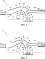
- the control system 28 is configured to detect the presence of the particles suspended in the inlet flow 46 and to move selectively the adaptive-curvature inner wall 22 between a non-austere arrangement, shown in Fig. 2 , and an austere arrangement, shown in Fig. 3 , in response to the control system 28 detecting the particles.
- the adaptive-curvature inner wall 22 has a first maximum radius 48.
- the adaptive-curvature inner wall 22 has a second maximum radius 50 that is greater than the first maximum radius 48.
- the hub geometry of the adaptive-curvature inner wall 22 would retract and assume the non-austere arrangement to provide a low pressure loss flow path.
- the hub geometry of the adaptive-curvature inner wall 22 would expand radially to force particulates into the scavenge channel 34.
- control system 28 includes a sensor 52 located in the air-inlet passageway 30 so that the control system 28 detects the particles in the air-inlet passageway 30. In some embodiments, the control system 28 includes the sensor 52 located in the engine channel 32 so that the control system 28 detects the particles in the engine channel 32. In some embodiments, the control system 28 includes the sensor 52 located in the scavenge channel 34 so that the control system 28 detects the particles in the scavenge channel 34.
- the control system 28 includes one or more actuators 58 configured to move the adaptive-curvature inner wall 22.
- a diagrammatic actuator 58 is shown in Figs. 2 and 3 .
- the actuators 58 may include linear actuators, pneumatic or fluid bladders, heating elements, rotatable rotors, or any other suitable alternative.
- the control system 28 may include a plurality of actuators 58, for example, to control precisely a contour of the adaptive-curvature inner wall 22.
- the illustrative particle separator 12 comprises a radially inward turning particle separator 12 as shown in Fig. 2 .
- the particle separator 12 comprises an inward turning particle separator, outward turning particle separator, linear type particle separator, dual path type particle separator, multi-path particle separators, or any combination thereof.
- FIG. 4 An embodiment of a particle separator 212 in accordance with the present disclosure is shown in Fig. 4 .
- the particle separator 212 is substantially similar to the particle separator 12 shown in Figs. 1-3 and described herein. Accordingly, similar reference numbers in the 200 series indicate features that are common between the particle separator 12 and the particle separator 212.
- the description of the particle separator 12 is incorporated by reference to apply to the particle separator 212, except in instances when it conflicts with the specific description and the drawings of the particle separator 212.
- the particle separator 212 includes an adaptive-curvature inner wall 222, the outer wall 24, the splitter 26, and the control system 28 as shown in Fig. 4 .
- the adaptive-curvature inner wall 222 includes a plurality of overlapping leaves 256 and the control system 28 includes an actuator 258.
- the plurality of overlapping leaves 256 are configured to slide relative to one another in response to the adaptive-curvature inner wall 222 moving between the first arrangement and the second arrangement.
- the actuator 258 is coupled to the plurality of leaves 256 and the control system 28.
- the actuator 258 is configured to move the plurality of leaves 256 in response to the control system 28 detecting the particles to move the adaptive-curvature inner wall 222 from the non-austere arrangement to the austere arrangement.
- the plurality of overlapping leaves 256 includes a first leaf 260 and a second leaf 262 located downstream of the first leaf as shown in Figs. 4 and 4A .
- the first leaf 260 includes a fore end 266 and an aft end 268 spaced axially apart from the fore end 266.
- the second leaf 262 includes a fore end 267 and an aft end 269 spaced axially apart from the fore end 267.
- the aft end 268 of the first leaf 260 is located radially outward and overlaps the fore end 267 of the second leaf 262.
- the aft end of each leaf is located radially outward and overlaps the fore end of the downstream adjacent leaf. As such, the chance of air and particles catching on abrupt surfaces of the leaves 256 is minimized.
- the plurality of overlapping leaves 256 are configured to slide relative to one another in the illustrative embodiment as suggested in Fig. 4A .
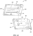
- the plurality of overlapping leaves 256 each include one or more pins 284 and one or more pin-receiving slots 286 as shown in Fig. 4A .
- the pins 284 included in the second leaf 262 are adapted to be received in the pin-receiving slots 286 formed in the first leaf 260 as suggested in Fig. 4A .
- the pin-receiving slots 286 are axially extending and allow the pins 284 to slide in the slots.
- Each of the plurality of overlapping leaves 256 further include flap seals 288 configured to provide a transition surface between leaves 256 and to block particles from flowing between leaves 256.
- the plurality of overlapping leaves 256 defines an internal cavity 270 as shown in Fig. 4 .
- the internal cavity 270 is in fluid communication with a pressurized air source configured to pressurize the cavity to block particles from moving between leaves 256 and into the internal cavity 270.
- the actuator 258 includes a linear actuator configured to move the adaptive-curvature inner wall 222 between the non-austere arrangement and the austere arrangement. In some embodiments, the actuator 258 includes a pneumatic bladder configured to move the adaptive-curvature inner wall 222 between the non-austere arrangement and austere second arrangement.
- FIG. 5 Another embodiment of a particle separator 312 in accordance with the present disclosure is shown in Fig. 5 .
- the particle separator 312 is substantially similar to the particle separator 12 shown in Figs. 1-3 and described herein. Accordingly, similar reference numbers in the 300 series indicate features that are common between the particle separator 12 and the particle separator 312.
- the description of the particle separator 12 is incorporated by reference to apply to the particle separator 312, except in instances when it conflicts with the specific description and the drawings of the particle separator 312.
- the particle separator 312 includes an adaptive-curvature inner wall 322, the outer wall 24, the splitter 26, and the control system 28 as shown in Fig. 5 .
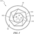
- the adaptive-curvature inner wall 322 includes a rotor 370, a plurality of leaves 372, and a plurality of support struts 374.
- the rotor 370 extends axially relative to the axis 38.
- the plurality of leaves 372 are arranged circumferentially about the rotor 370 to locate radially the plurality of leaves 372 between the outer wall 24 and the rotor 370.
- the plurality of support struts 374 are pivotably coupled to the rotor 370 and pivotably coupled to the plurality of leaves 372.
- the control system 28 is configured to rotate selectively the rotor 370 about the axis 38 to move the plurality of leaves 372 radially inward and outward to cause the adaptive-curvature inner wall 322 to move between the non-austere arrangement and the austere arrangement.
- the struts 374 urge the leaves 372 radially inward and outward.
- each strut 374 is coupled pivotably to a pair of adjacent leaves 372.
- the struts 374 are about equally spaced apart from one another about the rotor 370.
- FIG. 6 and 7 Another embodiment of a particle separator 412 in accordance with the present disclosure is shown in Figs. 6 and 7 .
- the particle separator 412 is substantially similar to the particle separator 12 shown in Figs. 1-3 and described herein. Accordingly, similar reference numbers in the 400 series indicate features that are common between the particle separator 12 and the particle separator 412.
- the description of the particle separator 12 is incorporated by reference to apply to the particle separator 412, except in instances when it conflicts with the specific description and the drawings of the particle separator 412.
- the particle separator 412 includes an adaptive-curvature inner wall 422, the outer wall 24, the splitter 26, and the control system 28 as shown in Figs. 6 and 7 .
- the adaptive-curvature inner wall 422 includes a surface layer 480 that extends at least partway about the axis 38 and a plurality of heating elements 482.
- the heating elements 482 are located radially inward of the surface layer 480.
- the surface layer 480 comprises Shape Memory Alloy material.
- the control system 28 is configured to cause the plurality of heating elements 482 to heat the surface layer 480 to cause the adaptive-curvature inner wall 422 to move from the non-austere arrangement shown in Fig. 6 to the austere arrangement shown in Fig. 7 in response to the control system 28 detecting the particles.
- the plurality of heating elements 482 are spaced apart axially from one another.
- the control system 28 is configured to power each of the plurality of heating elements 482 individually to control a contour of the surface layer 480.
- a method in accordance with the present disclosure includes providing a particle separator 12, 212, 312, 412 that includes an inner wall 22, 222, 322, 422, an outer wall 24 arranged around the inner wall 22, 222, 322, 422 to define an inlet passageway 30, and a splitter 26 located between the inner wall 22, 222, 322, 422 and the outer wall 24.
- the method further includes providing a mixture of air and particles suspended in the air to the inlet passageway 30.
- the method includes separating the mixture of air and particles suspended in the air into a dirty flow 42 including substantially all the particles and a clean flow 40 lacking substantially all the particles.
- the method may include detecting the particles suspended in the mixture of air and particles.
- the method includes moving at least a portion of the inner wall 22, 222, 322, 422 toward the outer wall 24 in response to detecting the particles. In some embodiments, at least a portion of the inner wall 22, 222, 322, 422 is moved toward the outer wall 24 in response to operator input.
- the determining step includes detecting particles in the inlet passageway 30. In some embodiments, the determining step includes detecting the particles in the engine channel 32. In some embodiments, the method further includes providing pressurized fluid to the internal cavity defined by the inner wall 22, 222, 322, 422.
- the moving step includes sliding the first leaf 260 relative to and over the second leaf 262.
- the inner wall 422 comprises shape memory alloy materials and the moving step includes heating the inner wall 422.
- the moving step includes rotating the rotor 370 about the axis 38 to move the plurality of leaves 372 radially.
- Fixed and rotary wing aircraft may operate in particulate laden environments such as deserts or beach areas. Small particulates can affect aircraft gas turbine engines, whether during conventional takeoff/landing or vertical take-off and landing. In flight, engines may ingest ice crystals or volcanic ash. Some of these engines may use filters to remove particulates from entering the gas turbine engine and therefore protect the hot section hardware from damage.
- the engine 10 includes an inertial particle separator (IPS) to remove a significant portion of particulates and expel them via a scavenge duct system outside of the aircraft.
- Aircraft may use turboshaft gas turbine engines to power the rotor blades.
- the inertial particle separators 12 may be located ahead of the engine and be included as part of the inlet duct system. As shown in Figs. 2 and 3 , atmospheric air enters the inlet passage "inflow" and the flow bifurcates into the engine inlet flow "core flow” and the bypass “scavenge flow” that carries the particulates away from the engine inlet by dumping the flow overboard.
- the scavenge ratio may be increased to increase the capture of particles into the scavenge duct.
- the flow turning may be increased to force more particles into the scavenge duct.
- the scavenge ratio may be calculated as the ratio of the amount of flow entering the scavenge duct to the total flow entering the inlet.
- the amount of scavenge flow may be limited by the amount of the inlet flow the engine requires. Once this limit has been reached, another available option may be to increase the amount of flow turning in the duct.
- the hub may be desirable to have the hub at a high flow turning position only when particulates are present (austere conditions). When no particulates are present (non-austere environment), the pressure loss may be much lower. This may be effectively changing the curvature of the hub surface.
- the present disclosure provides an approach to achieving this by incorporating a radially variable geometry hub into an inertial particle separator flow path. When particulates are present, the hub would expand radially to force particulates into the scavenge duct. When in non-austere conditions, the hub geometry would retract to a low pressure loss flow path.
- the present disclosure is applicable for inertial particle separators in turboshaft or turbofan applications.
- a sensor could be used to detect the presence of particulates.
- An actuator could be used to push the hub geometry radially outward for austere conditions and inward for non-austere conditions. The use of scavenge flow may control pressure loss due to possible excessive diffusion.
- the hub surface could be made of overlapping metallic surfaces ("leafs" or “turkey feathers") that allow for expansion and contraction of the local geometry using an internal actuator as shown in Fig. 4 .
- the hub height and curvature could be changed by a rotating drum attached to several metallic leafs as shown in Fig. 5 . As the drum rotates in a first direction, the hub surface expands and as the drum rotates in an opposite second direction, the drum surface contracts.
- Shape Memory Alloy SMA or smart metal
- Electrical heating elements may be employed under the surface to deform the hub surface to the desired shape for austere conditions as shown in Fig. 7 .
- the surface may return to a low pressure loss shape for non-austere conditions as shown in Fig. 6 .
- the subject matter of the disclosure may also relate, among others, to the following aspects:
Landscapes
- Engineering & Computer Science (AREA)
- Chemical & Material Sciences (AREA)
- Combustion & Propulsion (AREA)
- Mechanical Engineering (AREA)
- General Engineering & Computer Science (AREA)
- Physics & Mathematics (AREA)
- Geometry (AREA)
- Separating Particles In Gases By Inertia (AREA)
- Cyclones (AREA)
Abstract
Description
- The present disclosure relates generally to gas turbine engines, and more specifically to particle separators adapted for use with gas turbine engines.
- Gas turbine engines are used to power aircraft, watercraft, power generators, and the like. Gas turbine engines typically include a compressor, a combustor, and a turbine. The compressor compresses air drawn into the engine and delivers high pressure air to the combustor. In the combustor, fuel is mixed with the high pressure air and the fuel and air is ignited. Products of the combustion reaction in the combustor are directed into the turbine where work is extracted to drive the compressor and, sometimes, an output shaft. Left-over products of the combustion are exhausted out of the turbine and may provide thrust in some applications.
- Air is drawn into the engine through an air inlet and communicated to the compressor via an air-inlet duct. In some operating conditions, particles may be entrained in the air such as dust, sand, ash, or water and may be drawn into the air inlet and passed through the air-inlet duct to the compressor. Such particles may impact components of the compressor and turbine causing unintended wear. This unintended wear may decrease power output of the engine, shorten the life span of the engine, and lead to increased maintenance costs and increased down time of the engine.
- One method of separating particles from air entering the compressor has been by inertial particle separation. Inertial particle separation uses the inertia of the particles to separate the particles from the air. As the air stream moves through the air-inlet duct, the air moves along a serpentine flow path and enters an engine channel of the air-inlet duct while the particles move along a generally linear travel path and enter a scavenge channel of the particle separator.
- The present disclosure provides a particle separator and a method as set out in the appended claims.
- The present disclosure may comprise one or more of the following features and combinations thereof.
- In a first aspect, the present disclosure provides a particle separator that may include an adaptive-curvature inner wall arranged circumferentially about an axis, an outer wall, a splitter, and a control system. The outer wall may be arranged circumferentially about the adaptive-curvature inner wall to define an inlet passage of the particle separator. The inlet passage may be adapted to receive a mixture of air and particles suspended in the air. The splitter may be located radially between the outer wall and the adaptive-curvature inner wall to separate the mixture of air and particles into a clean flow substantially free of particles and a dirty flow containing the particles during operation of the particle separator. The splitter and the adaptive-curvature inner wall may define an engine channel arranged to receive the clean flow. The splitter and the outer wall may define a scavenge channel arranged to receive the dirty flow.
- The control system may be configured to detect the presence of the particles suspended in the air. The control system may be configured to move selectively the adaptive-curvature inner wall between a non-austere arrangement in which the adaptive-curvature inner wall has a first maximum radius and an austere arrangement in which the adaptive-curvature inner wall has a second maximum radius greater than the first maximum radius in response to the control system detecting the presence of the particles.
- In some embodiments, the adaptive-curvature inner wall may include a plurality of overlapping leaves. Each of plurality of overlapping leaves may be configured to slide relative to one another in response to the adaptive-curvature inner wall moving between the first arrangement and the second arrangement.
- In some embodiments, the plurality of overlapping leaves may include a first leaf and a second leaf located downstream of the first leaf. The first leaf and the second leaf may each include a fore end and an aft end spaced axially apart from the fore end. The aft end of the first leaf may be located radially outward and overlap the fore end of the second leaf. In some embodiments, the plurality of overlapping leaves may define an internal cavity that is in fluid communication with a pressurized air source.
- In some embodiments, the control system may include a linear actuator configured to move the adaptive-curvature inner wall between the non-austere arrangement and the austere arrangement. In some embodiments, the control system may include a pneumatic bladder configured to move the adaptive-curvature inner wall between the non-austere arrangement and austere second arrangement.
- In some embodiments, the adaptive-curvature inner wall may include a rotor, a plurality of leaves, and a plurality of support struts. The rotor may extend axially relative to the axis. The plurality of leaves may be arranged circumferentially about the rotor. The plurality of support struts may be pivotably coupled to the rotor and pivotably coupled to the plurality of leaves. In some embodiments, the control system may be configured to rotate selectively the rotor about the axis to move the plurality of leaves radially inward and outward to cause the adaptive-curvature inner wall to move between the non-austere arrangement and the austere arrangement.
- In some embodiments, the adaptive-curvature inner wall may include a surface layer that extends at least partway about the axis and a plurality of heating elements located radially inward of the surface layer. The surface layer may comprise shape memory alloy. The control system may be configured to cause the plurality of heating elements to heat the surface layer to cause the adaptive-curvature inner wall to move from the non-austere arrangement to the austere arrangement.
- In some embodiments, the plurality of heating elements may be spaced apart axially from one another. The control system may be configured to power each of the plurality of heating elements individually to control a contour of the surface layer.
- According to second aspect of the present disclosure, a method includes a number of steps. The method may include providing a particle separator that includes an inner wall, an outer wall arranged around the inner wall to define an inlet passageway, and a splitter located between the inner wall and the outer wall, providing a mixture of air and particles suspended in the air to the inlet passageway, separating the mixture of air and particles suspended in the air into a dirty flow including substantially all the particles and a clean flow lacking substantially all the particles, detecting the particles suspended in the mixture of air and particles, and moving at least a portion of the inner wall toward the outer wall in response to detecting the particles.
- In some embodiments, the splitter and the inner wall may define an engine channel. The splitter and the outer wall may define a scavenge channel. The inlet passageway may be in fluid communication with the engine channel and the scavenge channel. The detecting step may include detecting particles in the inlet passageway.
- In some embodiments, the splitter and the inner wall may define an engine channel. The splitter and the outer wall may define a scavenge channel. The inlet passageway may be in fluid communication with the engine channel and the scavenge channel. The detecting step may include detecting the particles in the engine channel.
- In some embodiments, the splitter may be fixed in position relative to the outer wall. In some embodiments, the inner wall may define an internal cavity. The method may further include providing pressurized fluid to the internal cavity.
- In some embodiments, the inner wall may include a first leaf and a second leaf. The first leaf may overlap the second leaf. The moving step may include sliding the first leaf relative to and over the second leaf.
- In some embodiments, the second leaf may be located downstream of the first leaf. The first leaf and the second leaf may each include a fore end and an aft end spaced axially apart from the fore end. The aft end of the first leaf may be located radially outward and overlap the fore end of the second leaf.
- In some embodiments, the inner wall may define an internal cavity. The method may further include providing pressurized fluid to the internal cavity.
- In some embodiments, the inner wall may comprise shape memory alloy materials. The moving step may include heating the inner wall.
- In some embodiments, the inner wall may include a rotor that extends along an axis. The plurality of leaves may be arranged circumferentially about the rotor. The plurality of support struts may be pivotably coupled to the rotor and may be pivotably coupled to the plurality of leaves. In some embodiments, the moving step may include rotating the rotor about the axis to move the plurality of leaves radially.
- According to a third aspect the present disclosure also provides a gas turbine engine comprising a particle separator of the first aspect.
- These and other features of the present disclosure will become more apparent from the following description of the illustrative embodiments.
-
-
Fig. 1 is a cut-away perspective view of a gas turbine engine having a particle separator in accordance with the present disclosure, the gas turbine engine including the particle separator, a compressor section, a combustor section, and a turbine section; -
Fig. 2 is an enlarged section and diagrammatic view of the particle separator ofFig. 1 showing that the particle separator includes an adaptive-curvature inner wall arranged circumferentially about an axis, an outer wall arranged circumferentially about the adaptive-curvature inner wall to define an inlet passageway into the particle separator, and a splitter located between the adaptive-curvature inner wall and the outer wall to define an engine channel and a scavenge channel; -
Fig. 3 is a view similar toFig. 2 showing that the adaptive-curvature inner wall has moved toward the outer wall in response to the detection of particles suspended in the airflow provided to the inlet passageway of the particle separator; -
Fig. 4 is a diagrammatic similar toFig. 2 showing one embodiment of a particle separator having a plurality of overlapping leaves configured to move relative to one another in response to movement of the adaptive-curvature inner wall; -
Fig. 4A is an exploded view of a pair of overlapping leaves included in the particle separator ofFig. 4 ; -
Fig. 5 is an front elevation and diagrammatic view showing another embodiment of a particle separator having a plurality of leaves arranged around an axis of the engine, the plurality of leaves being coupled to a rotor configured to rotate and move the plurality of leaves radially inward and outward to adjust an arrangement of the adjustable-curvature inner wall; -
Fig. 6 is a section and diagrammatic view of another embodiment of a particle separator wherein the adaptive -curvature inner wall includes a surface comprising shape memory alloys and a plurality of heating elements configured to heat the surface; and -
Fig. 7 is a view similar toFig. 6 showing the surface of the adaptive -curvature inner wall has moved in response to being heated by the heating elements. - For the purposes of promoting an understanding of the principles of the disclosure, reference will now be made to a number of illustrative embodiments illustrated in the drawings and specific language will be used to describe the same.
- A
gas turbine engine 10 in accordance with the present disclosure is shown, for example, inFig. 1 . Thegas turbine engine 10 includes aparticle separator 12, acompressor section 14, acombustor section 16, and aturbine section 18. Air is drawn into thegas turbine engine 10 throughparticle separator 12 prior to admission of the air into thecompressor section 14 as suggested inFigs. 1 and2 . Thecompressor section 14 compresses the air drawn into theengine 10 and delivers high-pressure air to thecombustor section 16. Thecombustor section 16 is configured to ignite a mixture of the compressed air and fuel. Products of the combustion process are directed into theturbine section 18 where work is extracted to drive thecompressor section 14 and a fan, propeller, output shaft, or gearbox. - In some environments, particles such as dirt, sand, ash, and/or water may be entrained in the air surrounding the
engine 10. Such environments may be referred to as austere conditions. In contrast, environments having relatively low or no particles may be referred to as non-austere conditions. The particles may be carried into thegas turbine engine 10 and possibly damage and wear engine components. Theillustrative particle separator 12 is configured to separate the particles from the air to provide clean air substantially free from particles to thecompressor section 14 so that damage to theengine 10 is minimized. - The
illustrative particle separator 12 includes an adaptive-curvatureinner wall 22, anouter wall 24, asplitter 26, and acontrol system 28 as shown inFig. 2 . The adaptive-curvatureinner wall 22 is annular and is located in spaced-apart relation to anengine rotation axis 38. Theouter wall 24 is also annular and is arranged circumferentially around the adaptive-curvatureinner wall 22 and theengine rotation axis 38. The adaptive-curvatureinner wall 22 and theouter wall 24 cooperate to define an air-inlet passageway 30 therebetween as shown inFigs. 2 and 3 . In the illustrative embodiment, the adaptive-curvatureinner wall 22 defines aninternal cavity 70 as shown inFig. 2 . - The
splitter 26 is located between the adaptive-curvatureinner wall 22 and theouter wall 24 as shown inFig. 2 . Thesplitter 26 cooperates with the adaptive-curvatureinner wall 22 to define anengine channel 32 therebetween as shown inFig. 2 . Thesplitter 26 cooperates with theouter wall 24 to define thescavenge channel 34 therebetween. Thesplitter 26 separates the flow of air and particles that are conducted into the air-inlet passageway into aclean flow 40 and adirty flow 42 as suggested inFig. 2 . Theclean flow 40 is conducted to thecompressor section 14 via theengine channel 32. Thedirty flow 42 is conducted to thescavenge channel 34. Thesplitter 26 is fixed in position relative to theouter wall 24 in the illustrative embodiments. - In use, an
inlet flow 46 is conducted into the air-inlet passageway 30 of the particle separator as suggested inFig. 2 . Thecontrol system 28 is configured to detect the presence of the particles suspended in theinlet flow 46 and to move selectively the adaptive-curvatureinner wall 22 between a non-austere arrangement, shown inFig. 2 , and an austere arrangement, shown inFig. 3 , in response to thecontrol system 28 detecting the particles. In the non-austere arrangement, the adaptive-curvatureinner wall 22 has a firstmaximum radius 48. In the austere arrangement, the adaptive-curvatureinner wall 22 has a secondmaximum radius 50 that is greater than the firstmaximum radius 48. - In non-austere conditions, the hub geometry of the adaptive-curvature
inner wall 22 would retract and assume the non-austere arrangement to provide a low pressure loss flow path. In austere conditions, the hub geometry of the adaptive-curvatureinner wall 22 would expand radially to force particulates into thescavenge channel 34. - In some embodiments, the
control system 28 includes asensor 52 located in the air-inlet passageway 30 so that thecontrol system 28 detects the particles in the air-inlet passageway 30. In some embodiments, thecontrol system 28 includes thesensor 52 located in theengine channel 32 so that thecontrol system 28 detects the particles in theengine channel 32. In some embodiments, thecontrol system 28 includes thesensor 52 located in thescavenge channel 34 so that thecontrol system 28 detects the particles in thescavenge channel 34. - In some embodiments, the
control system 28 includes one ormore actuators 58 configured to move the adaptive-curvatureinner wall 22. Adiagrammatic actuator 58 is shown inFigs. 2 and 3 . Theactuators 58 may include linear actuators, pneumatic or fluid bladders, heating elements, rotatable rotors, or any other suitable alternative. Thecontrol system 28 may include a plurality ofactuators 58, for example, to control precisely a contour of the adaptive-curvatureinner wall 22. - The
illustrative particle separator 12 comprises a radially inwardturning particle separator 12 as shown inFig. 2 . In other embodiments, theparticle separator 12 comprises an inward turning particle separator, outward turning particle separator, linear type particle separator, dual path type particle separator, multi-path particle separators, or any combination thereof. - An embodiment of a
particle separator 212 in accordance with the present disclosure is shown inFig. 4 . Theparticle separator 212 is substantially similar to theparticle separator 12 shown inFigs. 1-3 and described herein. Accordingly, similar reference numbers in the 200 series indicate features that are common between theparticle separator 12 and theparticle separator 212. The description of theparticle separator 12 is incorporated by reference to apply to theparticle separator 212, except in instances when it conflicts with the specific description and the drawings of theparticle separator 212. - The
particle separator 212 includes an adaptive-curvatureinner wall 222, theouter wall 24, thesplitter 26, and thecontrol system 28 as shown inFig. 4 . The adaptive-curvatureinner wall 222 includes a plurality of overlapping leaves 256 and thecontrol system 28 includes anactuator 258. - The plurality of overlapping leaves 256 are configured to slide relative to one another in response to the adaptive-curvature
inner wall 222 moving between the first arrangement and the second arrangement. Theactuator 258 is coupled to the plurality ofleaves 256 and thecontrol system 28. Theactuator 258 is configured to move the plurality ofleaves 256 in response to thecontrol system 28 detecting the particles to move the adaptive-curvatureinner wall 222 from the non-austere arrangement to the austere arrangement. - The plurality of overlapping leaves 256 includes a
first leaf 260 and asecond leaf 262 located downstream of the first leaf as shown inFigs. 4 and4A . Thefirst leaf 260 includes afore end 266 and anaft end 268 spaced axially apart from thefore end 266. Thesecond leaf 262 includes afore end 267 and anaft end 269 spaced axially apart from thefore end 267. Theaft end 268 of thefirst leaf 260 is located radially outward and overlaps thefore end 267 of thesecond leaf 262. Illustratively, the aft end of each leaf is located radially outward and overlaps the fore end of the downstream adjacent leaf. As such, the chance of air and particles catching on abrupt surfaces of theleaves 256 is minimized. - The plurality of overlapping leaves 256 are configured to slide relative to one another in the illustrative embodiment as suggested in
Fig. 4A . The plurality of overlapping leaves 256 each include one ormore pins 284 and one or more pin-receivingslots 286 as shown inFig. 4A . Thepins 284 included in thesecond leaf 262 are adapted to be received in the pin-receivingslots 286 formed in thefirst leaf 260 as suggested inFig. 4A . The pin-receivingslots 286 are axially extending and allow thepins 284 to slide in the slots. Each of the plurality of overlapping leaves 256 further include flap seals 288 configured to provide a transition surface betweenleaves 256 and to block particles from flowing betweenleaves 256. - In the illustrative embodiment, the plurality of overlapping leaves 256 defines an
internal cavity 270 as shown inFig. 4 . Theinternal cavity 270 is in fluid communication with a pressurized air source configured to pressurize the cavity to block particles from moving betweenleaves 256 and into theinternal cavity 270. - In some embodiments, the
actuator 258 includes a linear actuator configured to move the adaptive-curvatureinner wall 222 between the non-austere arrangement and the austere arrangement. In some embodiments, theactuator 258 includes a pneumatic bladder configured to move the adaptive-curvatureinner wall 222 between the non-austere arrangement and austere second arrangement. - Another embodiment of a
particle separator 312 in accordance with the present disclosure is shown inFig. 5 . Theparticle separator 312 is substantially similar to theparticle separator 12 shown inFigs. 1-3 and described herein. Accordingly, similar reference numbers in the 300 series indicate features that are common between theparticle separator 12 and theparticle separator 312. The description of theparticle separator 12 is incorporated by reference to apply to theparticle separator 312, except in instances when it conflicts with the specific description and the drawings of theparticle separator 312. - The
particle separator 312 includes an adaptive-curvatureinner wall 322, theouter wall 24, thesplitter 26, and thecontrol system 28 as shown inFig. 5 . The adaptive-curvatureinner wall 322 includes arotor 370, a plurality ofleaves 372, and a plurality of support struts 374. Therotor 370 extends axially relative to theaxis 38. The plurality ofleaves 372 are arranged circumferentially about therotor 370 to locate radially the plurality ofleaves 372 between theouter wall 24 and therotor 370. The plurality of support struts 374 are pivotably coupled to therotor 370 and pivotably coupled to the plurality ofleaves 372. - The
control system 28 is configured to rotate selectively therotor 370 about theaxis 38 to move the plurality ofleaves 372 radially inward and outward to cause the adaptive-curvatureinner wall 322 to move between the non-austere arrangement and the austere arrangement. When therotor 370 rotates, thestruts 374 urge theleaves 372 radially inward and outward. In the illustrative embodiment, eachstrut 374 is coupled pivotably to a pair of adjacent leaves 372. Thestruts 374 are about equally spaced apart from one another about therotor 370. - Another embodiment of a
particle separator 412 in accordance with the present disclosure is shown inFigs. 6 and 7 . Theparticle separator 412 is substantially similar to theparticle separator 12 shown inFigs. 1-3 and described herein. Accordingly, similar reference numbers in the 400 series indicate features that are common between theparticle separator 12 and theparticle separator 412. The description of theparticle separator 12 is incorporated by reference to apply to theparticle separator 412, except in instances when it conflicts with the specific description and the drawings of theparticle separator 412. - The
particle separator 412 includes an adaptive-curvatureinner wall 422, theouter wall 24, thesplitter 26, and thecontrol system 28 as shown inFigs. 6 and 7 . The adaptive-curvatureinner wall 422 includes asurface layer 480 that extends at least partway about theaxis 38 and a plurality ofheating elements 482. Illustratively, theheating elements 482 are located radially inward of thesurface layer 480. Thesurface layer 480 comprises Shape Memory Alloy material. Thecontrol system 28 is configured to cause the plurality ofheating elements 482 to heat thesurface layer 480 to cause the adaptive-curvatureinner wall 422 to move from the non-austere arrangement shown inFig. 6 to the austere arrangement shown inFig. 7 in response to thecontrol system 28 detecting the particles. - Illustratively, the plurality of
heating elements 482 are spaced apart axially from one another. Thecontrol system 28 is configured to power each of the plurality ofheating elements 482 individually to control a contour of thesurface layer 480. - A method in accordance with the present disclosure includes providing a
particle separator inner wall outer wall 24 arranged around theinner wall inlet passageway 30, and asplitter 26 located between theinner wall outer wall 24. The method further includes providing a mixture of air and particles suspended in the air to theinlet passageway 30. The method includes separating the mixture of air and particles suspended in the air into adirty flow 42 including substantially all the particles and aclean flow 40 lacking substantially all the particles. - The method may include detecting the particles suspended in the mixture of air and particles. The method includes moving at least a portion of the
inner wall outer wall 24 in response to detecting the particles. In some embodiments, at least a portion of theinner wall outer wall 24 in response to operator input. - In some embodiments, the determining step includes detecting particles in the
inlet passageway 30. In some embodiments, the determining step includes detecting the particles in theengine channel 32. In some embodiments, the method further includes providing pressurized fluid to the internal cavity defined by theinner wall - In some embodiments, the moving step includes sliding the
first leaf 260 relative to and over thesecond leaf 262. In some embodiments, theinner wall 422 comprises shape memory alloy materials and the moving step includes heating theinner wall 422. In some embodiments, the moving step includes rotating therotor 370 about theaxis 38 to move the plurality ofleaves 372 radially. - Fixed and rotary wing aircraft may operate in particulate laden environments such as deserts or beach areas. Small particulates can affect aircraft gas turbine engines, whether during conventional takeoff/landing or vertical take-off and landing. In flight, engines may ingest ice crystals or volcanic ash. Some of these engines may use filters to remove particulates from entering the gas turbine engine and therefore protect the hot section hardware from damage.
- In the present application, the
engine 10 includes an inertial particle separator (IPS) to remove a significant portion of particulates and expel them via a scavenge duct system outside of the aircraft. Aircraft may use turboshaft gas turbine engines to power the rotor blades. Theinertial particle separators 12 may be located ahead of the engine and be included as part of the inlet duct system. As shown inFigs. 2 and 3 , atmospheric air enters the inlet passage "inflow" and the flow bifurcates into the engine inlet flow "core flow" and the bypass "scavenge flow" that carries the particulates away from the engine inlet by dumping the flow overboard. - Two approaches may be used increase the amount of particulates that are removed from an inertial particle separator. The scavenge ratio may be increased to increase the capture of particles into the scavenge duct. The flow turning may be increased to force more particles into the scavenge duct.
- The scavenge ratio may be calculated as the ratio of the amount of flow entering the scavenge duct to the total flow entering the inlet. The amount of scavenge flow may be limited by the amount of the inlet flow the engine requires. Once this limit has been reached, another available option may be to increase the amount of flow turning in the duct.
- The more the flow turning, the more particulates are forced into the scavenge duct. This increase in turning may be accomplished by increasing the maximum radial height of the hub of the
inner wall 22 from the horizontal direction. The more flow turning may result in higher pressure losses in the flow that enters the engine. - It may be desirable to have the hub at a high flow turning position only when particulates are present (austere conditions). When no particulates are present (non-austere environment), the pressure loss may be much lower. This may be effectively changing the curvature of the hub surface. The present disclosure provides an approach to achieving this by incorporating a radially variable geometry hub into an inertial particle separator flow path. When particulates are present, the hub would expand radially to force particulates into the scavenge duct. When in non-austere conditions, the hub geometry would retract to a low pressure loss flow path. The present disclosure is applicable for inertial particle separators in turboshaft or turbofan applications.
- A sensor could be used to detect the presence of particulates. An actuator could be used to push the hub geometry radially outward for austere conditions and inward for non-austere conditions. The use of scavenge flow may control pressure loss due to possible excessive diffusion.
- In some embodiments, the hub surface could be made of overlapping metallic surfaces ("leafs" or "turkey feathers") that allow for expansion and contraction of the local geometry using an internal actuator as shown in
Fig. 4 . In some embodiments, the hub height and curvature could be changed by a rotating drum attached to several metallic leafs as shown inFig. 5 . As the drum rotates in a first direction, the hub surface expands and as the drum rotates in an opposite second direction, the drum surface contracts. - In some embodiments, Shape Memory Alloy (SMA or smart metal) that changes when heated is used. Electrical heating elements may be employed under the surface to deform the hub surface to the desired shape for austere conditions as shown in
Fig. 7 . The surface may return to a low pressure loss shape for non-austere conditions as shown inFig. 6 . - While the disclosure has been illustrated and described in detail in the foregoing drawings and description, the same is to be considered as exemplary and not restrictive in character, it being understood that only illustrative embodiments thereof have been shown and described and that various changes and modifications are possible whilst remaining within the scope of the claims.
- The subject matter of the disclosure may also relate, among others, to the following aspects:
- 1. A particle separator for use with a gas turbine engine, the particle separator comprising:
- an adaptive-curvature inner wall arranged circumferentially about an axis;
- an outer wall arranged circumferentially about the adaptive-curvature inner wall to define an inlet passage of the particle separator, the inlet passage adapted to receive a mixture of air and particles suspended in the air;
- a splitter located radially between the outer wall and the adaptive-curvature inner wall to separate the mixture of air and particles into a clean flow substantially free of particles and a dirty flow containing the particles during operation of the particle separator, the splitter and the adaptive-curvature inner wall define an engine channel arranged to receive the clean flow, and the splitter and the outer wall define a scavenge channel arranged to receive the dirty flow; and
- a control system configured to detect a presence of the particles suspended in the air and to move selectively the adaptive-curvature inner wall between a non-austere arrangement in which the adaptive-curvature inner wall has a first maximum radius and an austere arrangement in which the adaptive-curvature inner wall has a second maximum radius greater than the first maximum radius in response to the control system detecting the presence of the particles.
- 2. The particle separator of aspect 1, wherein the adaptive-curvature inner wall includes a plurality of overlapping leaves configured to slide relative to one another in response to the adaptive-curvature inner wall moving between the non-austere arrangement and the austere arrangement.
- 3. The particle separator of aspect 2, wherein the plurality of overlapping leaves includes a first leaf and a second leaf located downstream of the first leaf, the first leaf and the second leaf each includes a fore end and an aft end spaced axially apart from the fore end, and the aft end of the first leaf is located radially outward and overlaps the fore end of the second leaf.
- 4. The particle separator of aspect 3, wherein the plurality of overlapping leaves define an internal cavity that is in fluid communication with a pressurized air source.
- 5. The particle separator of aspect 3, wherein the control system includes a linear actuator configured to move the adaptive-curvature inner wall between the non-austere arrangement and the austere arrangement.
- 6. The particle separator of aspect 3, wherein the control system includes a pneumatic bladder configured to move the adaptive-curvature inner wall between the non-austere arrangement and the austere arrangement.
- 7. The particle separator of aspect 1, wherein the adaptive-curvature inner wall includes a rotor that extends axially relative to the axis, a plurality of leaves arranged circumferentially about the rotor, and a plurality of support struts pivotably coupled to the rotor and pivotably coupled to the plurality of leaves.
- 8. The particle separator of aspect 7, wherein the control system is configured to rotate selectively the rotor about the axis to move the plurality of leaves radially inward and outward to cause the adaptive-curvature inner wall to move between the non-austere arrangement and the austere arrangement.
- 9. The particle separator of aspect 1, wherein the adaptive-curvature inner wall includes a surface layer that extends at least partway about the axis and a plurality of heating elements located radially inward of the surface layer, the surface layer comprises shape memory alloy, and the control system is configured to cause the plurality of heating elements to heat the surface layer to cause the adaptive-curvature inner wall to move from the non-austere arrangement to the austere arrangement.
- 10. The particle separator of aspect 9, wherein the plurality of heating elements are spaced apart axially from one another and the control system is configured to power each of the plurality of heating elements individually to control a contour of the surface layer.
- 11. A method comprising:
- providing a particle separator that includes an inner wall, an outer wall arranged around the inner wall to define an inlet passageway, and a splitter located between the inner wall and the outer wall;
- providing a mixture of air and particles suspended in the air to the inlet passageway;
- separating the mixture of air and particles suspended in the air into a dirty flow including substantially all the particles and a clean flow lacking substantially all the particles;
- detecting the particles suspended in the mixture of air and particles; and
- moving at least a portion of the inner wall toward the outer wall in response to detecting the particles.
- 12. The method of aspect 11, wherein the splitter and the inner wall define an engine channel, the splitter and the outer wall define a scavenge channel, the inlet passageway is in fluid communication with the engine channel and the scavenge channel, and the detecting step includes detecting particles in the inlet passageway.
- 13. The method of aspect 11, wherein the splitter and the inner wall define an engine channel, the splitter and the outer wall define a scavenge channel, the inlet passageway is in fluid communication with the engine channel and the scavenge channel, and the detecting step includes detecting the particles in the engine channel.
- 14. The method of aspect 11, wherein the splitter is fixed in position relative to the outer wall.
- 15. The method of aspect 11, wherein the inner wall defines an internal cavity and the method further includes providing pressurized fluid to the internal cavity.
- 16. The method of aspect 11, wherein the inner wall includes a first leaf and a second leaf, the first leaf overlaps the second leaf, and the moving step includes sliding the first leaf relative to and over the second leaf.
- 17. The method of
aspect 16, wherein the second leaf is located downstream of the first leaf, the first leaf and the second leaf each includes a fore end and an aft end spaced axially apart from the fore end, and the aft end of the first leaf is located radially outward and overlaps the fore end of the second leaf. - 18. The method of
aspect 16, wherein the inner wall defines an internal cavity and the method further includes providing pressurized fluid to the internal cavity. - 19. The method of aspect 11, wherein the inner wall comprises shape memory alloy materials and the moving step includes heating the inner wall.
- 20. The method of aspect 11, wherein the inner wall includes a rotor that extends along an axis, a plurality of leaves arranged circumferentially about the rotor, and a plurality of support struts pivotably coupled to the rotor and pivotably coupled to the plurality of leaves and the moving step includes rotating the rotor about the axis to move the plurality of leaves radially.
Claims (15)
- A particle separator (12) for use with a gas turbine engine (10), the particle separator comprising:an adaptive-curvature inner wall (22) arranged circumferentially about an axis,an outer wall arranged (24) circumferentially about the adaptive-curvature inner wall to define an inlet passage (30) of the particle separator, the inlet passage adapted to receive a mixture of air and particles suspended in the air;a splitter (26) located radially between the outer wall and the adaptive-curvature inner wall to separate the mixture of air and particles into a clean flow (40) substantially free of particles and a dirty flow (42) containing the particles during operation of the particle separator, the splitter and the adaptive-curvature inner wall defining an engine channel (32) arranged to receive the clean flow, and the splitter and the outer wall defining a scavenge channel (34) arranged to receive the dirty flow; anda control system (28) configured to detect a presence of the particles suspended in the air and to move selectively the adaptive-curvature inner wall between a non-austere arrangement in which the adaptive-curvature inner wall has a first maximum radius (48) and an austere arrangement in which the adaptive-curvature inner wall has a second maximum radius (50) greater than the first maximum radius in response to the control system detecting the presence of the particles.
- A particle separator according to claim 1, wherein the adaptive-curvature inner wall includes a plurality of overlapping leaves (256) configured to slide relative to one another in response to the adaptive-curvature inner wall moving between the non-austere arrangement and the austere arrangement.
- A particle separator according to claim 2, wherein the plurality of overlapping leaves define an internal cavity that is in fluid communication with a pressurized air source.
- A particle separator according to claim 2, wherein the control system comprises either a linear actuator or a pneumatic bladder configured to move the adaptive-curvature inner wall between the non-austere arrangement and the austere arrangement.
- A particle separator according to claim 1, wherein the adaptive-curvature inner wall includes a rotor that extends axially relative to the axis, a plurality of leaves arranged circumferentially about the rotor, and a plurality of support struts pivotably coupled to the rotor and pivotably coupled to the plurality of leaves.
- A particle separator according to claim 5, wherein the control system is configured to rotate selectively the rotor about the axis to move the plurality of leaves radially inward and outward to cause the adaptive-curvature inner wall to move between the non-austere arrangement and the austere arrangement.
- A particle separator according to claim 1, wherein the adaptive-curvature inner wall includes a surface layer that extends at least partway about the axis and a plurality of heating elements located radially inward of the surface layer, the surface layer comprising a shape memory alloy, and the control system is configured to cause the plurality of heating elements to heat the surface layer to cause the adaptive-curvature inner wall to move from the non-austere arrangement to the austere arrangement.
- A particle separator according to claim 7, wherein the plurality of heating elements are spaced apart axially from one another and the control system is configured to power each of the plurality of heating elements individually to control a contour of the surface layer.
- A method comprising:providing a particle separator that includes an inner wall, an outer wall arranged around the inner wall to define an inlet passageway, and a splitter located between the inner wall and the outer wall;providing a mixture of air and particles suspended in the air to the inlet passageway;detecting the particles suspended in the mixture of air and particles,moving at least a portion of the inner wall toward the outer wall in response to detecting the particles; andseparating the mixture of air and particles suspended in the air into a dirty flow including substantially all the particles and a clean flow lacking substantially all the particles.
- A method according to claim 9, wherein the splitter and the inner wall define an engine channel, the splitter and the outer wall define a scavenge channel, the inlet passageway is in fluid communication with the engine channel and the scavenge channel, and the detecting step includes detecting particles in the inlet passageway or the engine channel.
- A method according to claim 9, wherein the splitter is fixed in position relative to the outer wall.
- A method according to claim 9, wherein the inner wall includes a first leaf and a second leaf, the first leaf overlaps the second leaf, and the moving step includes sliding the first leaf relative to and over the second leaf.
- A method according to claim 9 or 12, wherein the inner wall defines an internal cavity and the method further includes providing pressurized fluid to the internal cavity.
- A method according to claim 9, wherein the inner wall comprises shape memory alloy materials and the moving step includes heating the inner wall.
- A method according to claim 9, wherein the inner wall includes a rotor that extends along an axis, a plurality of leaves arranged circumferentially about the rotor, and a plurality of support struts pivotably coupled to the rotor and pivotably coupled to the plurality of leaves and the moving step includes rotating the rotor about the axis to move the plurality of leaves radially.
Applications Claiming Priority (1)
| Application Number | Priority Date | Filing Date | Title |
|---|---|---|---|
| US15/914,589 US10767558B2 (en) | 2018-03-07 | 2018-03-07 | Adaptive-curvature inertial particle separators |
Publications (2)
| Publication Number | Publication Date |
|---|---|
| EP3536930A1 true EP3536930A1 (en) | 2019-09-11 |
| EP3536930B1 EP3536930B1 (en) | 2021-01-27 |
Family
ID=65365794
Family Applications (1)
| Application Number | Title | Priority Date | Filing Date |
|---|---|---|---|
| EP19156013.5A Active EP3536930B1 (en) | 2018-03-07 | 2019-02-07 | Adaptive-curvature inertial particle separators |
Country Status (3)
| Country | Link |
|---|---|
| US (1) | US10767558B2 (en) |
| EP (1) | EP3536930B1 (en) |
| CA (1) | CA3032347A1 (en) |
Families Citing this family (5)
| Publication number | Priority date | Publication date | Assignee | Title |
|---|---|---|---|---|
| US11560843B2 (en) * | 2020-02-25 | 2023-01-24 | General Electric Company | Frame for a heat engine |
| CN111648862A (en) * | 2020-04-30 | 2020-09-11 | 南京航空航天大学 | A flexible bulging center body structure of a variable particle separator and its design method |
| US11499478B2 (en) | 2020-11-19 | 2022-11-15 | Honeywell International Inc. | Asymmetric inlet particle separator for gas turbine engine |
| US11834988B1 (en) | 2022-06-15 | 2023-12-05 | Rolls-Royce North American Technologies Inc. | Turbine engine inertial particle separator with particle rebound suppression |
| US11964223B1 (en) * | 2022-10-15 | 2024-04-23 | Beta Air, Llc | Methods and apparatus for an inertial separation of air in an electric aircraft |
Citations (3)
| Publication number | Priority date | Publication date | Assignee | Title |
|---|---|---|---|---|
| US20030196548A1 (en) * | 2002-04-23 | 2003-10-23 | Hartman Peter A. | High particle separation efficiency system |
| EP1908939A2 (en) * | 2006-09-27 | 2008-04-09 | General Electric Company | Adaptive inertial particle separator |
| CN205618256U (en) * | 2016-05-09 | 2016-10-05 | 兰州大学 | Self -adaptation inertia particle separator |
Family Cites Families (38)
| Publication number | Priority date | Publication date | Assignee | Title |
|---|---|---|---|---|
| BE541578A (en) * | 1953-05-27 | |||
| US3444672A (en) | 1967-05-08 | 1969-05-20 | Michigan Dynamics Inc | Air cleaner for turbine engines |
| US3465950A (en) | 1968-01-22 | 1969-09-09 | Gen Electric | Separator |
| US3616616A (en) | 1968-03-11 | 1971-11-02 | Tech Dev Inc | Particle separator especially for use in connection with jet engines |
| US3521431A (en) | 1969-04-28 | 1970-07-21 | Avco Corp | Particle separator for engine air inlets |
| US3534548A (en) | 1969-06-30 | 1970-10-20 | Avco Corp | Separator apparatus for engine air inlets |
| US3673771A (en) | 1970-11-23 | 1972-07-04 | Avco Corp | Multi-channel particle separator |
| US3832086A (en) | 1971-11-23 | 1974-08-27 | Gen Electric | Particle separator with scroll scavenging means |
| US3733814A (en) | 1972-02-22 | 1973-05-22 | Gen Electric | Translatable engine inlet particle separator |
| US3778983A (en) | 1972-08-30 | 1973-12-18 | Avco Corp | Integral multichannel separator |
| US3970439A (en) | 1973-10-15 | 1976-07-20 | Avco Corporation | Particle separator |
| FR2250671B1 (en) | 1973-11-09 | 1980-01-04 | Aerospatiale | |
| US3979903A (en) | 1974-08-01 | 1976-09-14 | General Electric Company | Gas turbine engine with booster stage |
| US4196856A (en) * | 1977-11-25 | 1980-04-08 | The Boeing Company | Variable geometry convergent divergent exhaust nozzle |
| US4509962A (en) | 1983-10-06 | 1985-04-09 | Pratt & Whitney Canada Inc. | Inertial particle separator |
| US4617028A (en) | 1983-11-03 | 1986-10-14 | General Electric Company | Aircraft engine air intake including a foreign object separator |
| US4592765A (en) | 1985-01-15 | 1986-06-03 | Pratt & Whitney Canada Inc. | Inertial separator |
| US4702071A (en) | 1985-06-28 | 1987-10-27 | Rolls-Royce Plc | Inlet particle separator |
| US4704145A (en) | 1986-06-27 | 1987-11-03 | Avco Corporation | Modular multi-channel particle separator |
| GB2203801B (en) | 1987-04-14 | 1991-11-27 | Rolls Royce Plc | A gas turbine engine |
| US4928480A (en) | 1988-03-04 | 1990-05-29 | General Electric Company | Separator having multiple particle extraction passageways |
| US4860534A (en) | 1988-08-24 | 1989-08-29 | General Motors Corporation | Inlet particle separator with anti-icing means |
| US5039014A (en) * | 1989-04-11 | 1991-08-13 | General Electric Company | Axisymmetric vectoring exhaust nozzle seal |
| US5039317A (en) | 1990-07-05 | 1991-08-13 | Allied-Signal Inc. | Radial inflow particle separation method and apparatus |
| GB2250693B (en) | 1990-09-25 | 1994-01-26 | Rolls Royce Plc | Improvements in or relating to air intakes for gas turbine engines |
| US5226455A (en) * | 1990-12-17 | 1993-07-13 | Dupont Anthony A | Variable geometry duct seal |
| GB2259328B (en) | 1991-09-03 | 1995-07-19 | Gen Electric | Gas turbine engine variable bleed pivotal flow splitter |
| US6134874A (en) | 1998-06-02 | 2000-10-24 | Pratt & Whitney Canada Corp. | Integral inertial particle separator for radial inlet gas turbine engine |
| US6499285B1 (en) | 2001-08-01 | 2002-12-31 | Rolls-Royce Corporation | Particle separator for a gas turbine engine |
| EP1893862B1 (en) | 2005-06-20 | 2014-05-21 | Rolls-Royce North American Technologies, Inc. | Particle separators for gas turbine engines |
| EP2466097A1 (en) | 2005-06-20 | 2012-06-20 | Rolls-Royce North American Technologies, Inc. | Clustered inlet particle selector |
| US20080047425A1 (en) | 2006-08-23 | 2008-02-28 | United Technologies Corporation | Mission adaptable inlet particle separator |
| US7927408B2 (en) | 2007-11-30 | 2011-04-19 | Honeywell International Inc. | Inlet particle separator systems and methods |
| WO2010074934A1 (en) | 2008-12-26 | 2010-07-01 | Rolls-Royce North American Technologies, Inc. | Inlet particle separator system for a gas turbine engine |
| GB201115860D0 (en) | 2011-09-14 | 2011-10-26 | Rolls Royce Plc | A variable geometry structure |
| US20140237954A1 (en) | 2013-02-26 | 2014-08-28 | Rolls-Royce North American Technologies, Inc. | Particle separator |
| GB201412379D0 (en) * | 2014-07-11 | 2014-08-27 | Rolls Royce Plc | Ventilation inlet |
| EP3067532B1 (en) | 2015-03-11 | 2020-12-16 | Rolls-Royce North American Technologies, Inc. | Adaptable inertial particle separator for a gas turbine engine intake |
-
2018
- 2018-03-07 US US15/914,589 patent/US10767558B2/en active Active
-
2019
- 2019-02-01 CA CA3032347A patent/CA3032347A1/en active Pending
- 2019-02-07 EP EP19156013.5A patent/EP3536930B1/en active Active
Patent Citations (3)
| Publication number | Priority date | Publication date | Assignee | Title |
|---|---|---|---|---|
| US20030196548A1 (en) * | 2002-04-23 | 2003-10-23 | Hartman Peter A. | High particle separation efficiency system |
| EP1908939A2 (en) * | 2006-09-27 | 2008-04-09 | General Electric Company | Adaptive inertial particle separator |
| CN205618256U (en) * | 2016-05-09 | 2016-10-05 | 兰州大学 | Self -adaptation inertia particle separator |
Also Published As
| Publication number | Publication date |
|---|---|
| EP3536930B1 (en) | 2021-01-27 |
| US20190277198A1 (en) | 2019-09-12 |
| US10767558B2 (en) | 2020-09-08 |
| CA3032347A1 (en) | 2019-09-07 |
Similar Documents
| Publication | Publication Date | Title |
|---|---|---|
| EP3536930B1 (en) | Adaptive-curvature inertial particle separators | |
| EP3196442B1 (en) | Inlet particle separator for a turbine engine | |
| CN108952823B (en) | Method and system for leading edge auxiliary blade | |
| CA2113367C (en) | Method of operating an aircraft bypass turbofan engine having variable fan outlet guide vanes | |
| CN107120146B (en) | Active HPC Gap Control | |
| CA3048147C (en) | Particle separator assembly for a turbine engine | |
| EP2961934B1 (en) | Gas turbine engine variable geometry flow component | |
| EP3453840A1 (en) | Gas turbine engine active clearance control system using inlet particle separator | |
| EP3260687A1 (en) | Inlet particle separator system with pre-cleaner flow passage | |
| EP3179085B1 (en) | Fan blade apparatus | |
| CN111706402B (en) | Turbine engine pylon | |
| JP2017089624A (en) | Gas turbine engine having a flow control surface with cooling conduit | |
| US10400670B2 (en) | Inlet particle separator for a turbine engine | |
| JP6431950B2 (en) | Method and system for rotating an air seal having an integral flexible heat shield | |
| US20190024587A1 (en) | Fan integrated inertial particle separator | |
| US12618368B2 (en) | Gas turbine engine | |
| EP3546724B1 (en) | Adaptive-area inertial particle separators | |
| US11111855B2 (en) | Inlet particle separator | |
| EP3034815A1 (en) | Core case heating for gas turbine engines | |
| CN106988793A (en) | Nozzle assembly for gas-turbine unit | |
| CA3113984A1 (en) | Axial inertial particle separator for turbine engine | |
| US12416261B2 (en) | Gas turbine engine | |
| CN110015432A (en) | Engine nacelle for aircraft | |
| US20260036083A1 (en) | Turbine engine having a particle deflector assembly | |
| US20260062134A1 (en) | Assembly for identifying obstructing foreign matter in an air intake of an aircraft propulsion system and method of using same |
Legal Events
| Date | Code | Title | Description |
|---|---|---|---|
| PUAI | Public reference made under article 153(3) epc to a published international application that has entered the european phase |
Free format text: ORIGINAL CODE: 0009012 |
|
| STAA | Information on the status of an ep patent application or granted ep patent |
Free format text: STATUS: THE APPLICATION HAS BEEN PUBLISHED |
|
| AK | Designated contracting states |
Kind code of ref document: A1 Designated state(s): AL AT BE BG CH CY CZ DE DK EE ES FI FR GB GR HR HU IE IS IT LI LT LU LV MC MK MT NL NO PL PT RO RS SE SI SK SM TR |
|
| AX | Request for extension of the european patent |
Extension state: BA ME |
|
| STAA | Information on the status of an ep patent application or granted ep patent |
Free format text: STATUS: REQUEST FOR EXAMINATION WAS MADE |
|
| 17P | Request for examination filed |
Effective date: 20200228 |
|
| RBV | Designated contracting states (corrected) |
Designated state(s): AL AT BE BG CH CY CZ DE DK EE ES FI FR GB GR HR HU IE IS IT LI LT LU LV MC MK MT NL NO PL PT RO RS SE SI SK SM TR |
|
| RIC1 | Information provided on ipc code assigned before grant |
Ipc: B01D 45/06 20060101ALI20200511BHEP Ipc: F02C 7/042 20060101AFI20200511BHEP Ipc: F02C 7/052 20060101ALI20200511BHEP |
|
| GRAP | Despatch of communication of intention to grant a patent |
Free format text: ORIGINAL CODE: EPIDOSNIGR1 |
|
| STAA | Information on the status of an ep patent application or granted ep patent |
Free format text: STATUS: GRANT OF PATENT IS INTENDED |
|
| INTG | Intention to grant announced |
Effective date: 20200921 |
|
| RIN1 | Information on inventor provided before grant (corrected) |
Inventor name: SMITH III, CRAWFORD Inventor name: LERG, BRYAN |
|
| GRAS | Grant fee paid |
Free format text: ORIGINAL CODE: EPIDOSNIGR3 |
|
| GRAA | (expected) grant |
Free format text: ORIGINAL CODE: 0009210 |
|
| STAA | Information on the status of an ep patent application or granted ep patent |
Free format text: STATUS: THE PATENT HAS BEEN GRANTED |
|
| AK | Designated contracting states |
Kind code of ref document: B1 Designated state(s): AL AT BE BG CH CY CZ DE DK EE ES FI FR GB GR HR HU IE IS IT LI LT LU LV MC MK MT NL NO PL PT RO RS SE SI SK SM TR |
|
| REG | Reference to a national code |
Ref country code: GB Ref legal event code: FG4D |
|
| REG | Reference to a national code |
Ref country code: CH Ref legal event code: EP |
|
| REG | Reference to a national code |
Ref country code: AT Ref legal event code: REF Ref document number: 1358542 Country of ref document: AT Kind code of ref document: T Effective date: 20210215 |
|
| REG | Reference to a national code |
Ref country code: IE Ref legal event code: FG4D |
|
| REG | Reference to a national code |
Ref country code: DE Ref legal event code: R096 Ref document number: 602019002296 Country of ref document: DE |
|
| REG | Reference to a national code |
Ref country code: NL Ref legal event code: MP Effective date: 20210127 |
|
| REG | Reference to a national code |
Ref country code: LT Ref legal event code: MG9D |
|
| REG | Reference to a national code |
Ref country code: AT Ref legal event code: MK05 Ref document number: 1358542 Country of ref document: AT Kind code of ref document: T Effective date: 20210127 |
|
| PG25 | Lapsed in a contracting state [announced via postgrant information from national office to epo] |
Ref country code: BG Free format text: LAPSE BECAUSE OF FAILURE TO SUBMIT A TRANSLATION OF THE DESCRIPTION OR TO PAY THE FEE WITHIN THE PRESCRIBED TIME-LIMIT Effective date: 20210427 Ref country code: FI Free format text: LAPSE BECAUSE OF FAILURE TO SUBMIT A TRANSLATION OF THE DESCRIPTION OR TO PAY THE FEE WITHIN THE PRESCRIBED TIME-LIMIT Effective date: 20210127 Ref country code: HR Free format text: LAPSE BECAUSE OF FAILURE TO SUBMIT A TRANSLATION OF THE DESCRIPTION OR TO PAY THE FEE WITHIN THE PRESCRIBED TIME-LIMIT Effective date: 20210127 Ref country code: GR Free format text: LAPSE BECAUSE OF FAILURE TO SUBMIT A TRANSLATION OF THE DESCRIPTION OR TO PAY THE FEE WITHIN THE PRESCRIBED TIME-LIMIT Effective date: 20210428 Ref country code: PT Free format text: LAPSE BECAUSE OF FAILURE TO SUBMIT A TRANSLATION OF THE DESCRIPTION OR TO PAY THE FEE WITHIN THE PRESCRIBED TIME-LIMIT Effective date: 20210527 Ref country code: NO Free format text: LAPSE BECAUSE OF FAILURE TO SUBMIT A TRANSLATION OF THE DESCRIPTION OR TO PAY THE FEE WITHIN THE PRESCRIBED TIME-LIMIT Effective date: 20210427 Ref country code: LT Free format text: LAPSE BECAUSE OF FAILURE TO SUBMIT A TRANSLATION OF THE DESCRIPTION OR TO PAY THE FEE WITHIN THE PRESCRIBED TIME-LIMIT Effective date: 20210127 |
|
| PG25 | Lapsed in a contracting state [announced via postgrant information from national office to epo] |
Ref country code: AT Free format text: LAPSE BECAUSE OF FAILURE TO SUBMIT A TRANSLATION OF THE DESCRIPTION OR TO PAY THE FEE WITHIN THE PRESCRIBED TIME-LIMIT Effective date: 20210127 Ref country code: RS Free format text: LAPSE BECAUSE OF FAILURE TO SUBMIT A TRANSLATION OF THE DESCRIPTION OR TO PAY THE FEE WITHIN THE PRESCRIBED TIME-LIMIT Effective date: 20210127 Ref country code: LV Free format text: LAPSE BECAUSE OF FAILURE TO SUBMIT A TRANSLATION OF THE DESCRIPTION OR TO PAY THE FEE WITHIN THE PRESCRIBED TIME-LIMIT Effective date: 20210127 Ref country code: PL Free format text: LAPSE BECAUSE OF FAILURE TO SUBMIT A TRANSLATION OF THE DESCRIPTION OR TO PAY THE FEE WITHIN THE PRESCRIBED TIME-LIMIT Effective date: 20210127 Ref country code: SE Free format text: LAPSE BECAUSE OF FAILURE TO SUBMIT A TRANSLATION OF THE DESCRIPTION OR TO PAY THE FEE WITHIN THE PRESCRIBED TIME-LIMIT Effective date: 20210127 |
|
| REG | Reference to a national code |
Ref country code: DE Ref legal event code: R119 Ref document number: 602019002296 Country of ref document: DE |
|
| PG25 | Lapsed in a contracting state [announced via postgrant information from national office to epo] |
Ref country code: IS Free format text: LAPSE BECAUSE OF FAILURE TO SUBMIT A TRANSLATION OF THE DESCRIPTION OR TO PAY THE FEE WITHIN THE PRESCRIBED TIME-LIMIT Effective date: 20210527 |
|
| REG | Reference to a national code |
Ref country code: BE Ref legal event code: MM Effective date: 20210228 |
|
| PG25 | Lapsed in a contracting state [announced via postgrant information from national office to epo] |
Ref country code: SM Free format text: LAPSE BECAUSE OF FAILURE TO SUBMIT A TRANSLATION OF THE DESCRIPTION OR TO PAY THE FEE WITHIN THE PRESCRIBED TIME-LIMIT Effective date: 20210127 Ref country code: LU Free format text: LAPSE BECAUSE OF NON-PAYMENT OF DUE FEES Effective date: 20210207 Ref country code: MC Free format text: LAPSE BECAUSE OF FAILURE TO SUBMIT A TRANSLATION OF THE DESCRIPTION OR TO PAY THE FEE WITHIN THE PRESCRIBED TIME-LIMIT Effective date: 20210127 Ref country code: CZ Free format text: LAPSE BECAUSE OF FAILURE TO SUBMIT A TRANSLATION OF THE DESCRIPTION OR TO PAY THE FEE WITHIN THE PRESCRIBED TIME-LIMIT Effective date: 20210127 Ref country code: EE Free format text: LAPSE BECAUSE OF FAILURE TO SUBMIT A TRANSLATION OF THE DESCRIPTION OR TO PAY THE FEE WITHIN THE PRESCRIBED TIME-LIMIT Effective date: 20210127 |
|
| PG25 | Lapsed in a contracting state [announced via postgrant information from national office to epo] |
Ref country code: DK Free format text: LAPSE BECAUSE OF FAILURE TO SUBMIT A TRANSLATION OF THE DESCRIPTION OR TO PAY THE FEE WITHIN THE PRESCRIBED TIME-LIMIT Effective date: 20210127 Ref country code: SK Free format text: LAPSE BECAUSE OF FAILURE TO SUBMIT A TRANSLATION OF THE DESCRIPTION OR TO PAY THE FEE WITHIN THE PRESCRIBED TIME-LIMIT Effective date: 20210127 Ref country code: RO Free format text: LAPSE BECAUSE OF FAILURE TO SUBMIT A TRANSLATION OF THE DESCRIPTION OR TO PAY THE FEE WITHIN THE PRESCRIBED TIME-LIMIT Effective date: 20210127 |
|
| PLBE | No opposition filed within time limit |
Free format text: ORIGINAL CODE: 0009261 |
|
| STAA | Information on the status of an ep patent application or granted ep patent |
Free format text: STATUS: NO OPPOSITION FILED WITHIN TIME LIMIT |
|
| 26N | No opposition filed |
Effective date: 20211028 |
|
| PG25 | Lapsed in a contracting state [announced via postgrant information from national office to epo] |
Ref country code: IE Free format text: LAPSE BECAUSE OF NON-PAYMENT OF DUE FEES Effective date: 20210207 Ref country code: AL Free format text: LAPSE BECAUSE OF FAILURE TO SUBMIT A TRANSLATION OF THE DESCRIPTION OR TO PAY THE FEE WITHIN THE PRESCRIBED TIME-LIMIT Effective date: 20210127 Ref country code: DE Free format text: LAPSE BECAUSE OF NON-PAYMENT OF DUE FEES Effective date: 20210901 Ref country code: ES Free format text: LAPSE BECAUSE OF FAILURE TO SUBMIT A TRANSLATION OF THE DESCRIPTION OR TO PAY THE FEE WITHIN THE PRESCRIBED TIME-LIMIT Effective date: 20210127 |
|
| PG25 | Lapsed in a contracting state [announced via postgrant information from national office to epo] |
Ref country code: SI Free format text: LAPSE BECAUSE OF FAILURE TO SUBMIT A TRANSLATION OF THE DESCRIPTION OR TO PAY THE FEE WITHIN THE PRESCRIBED TIME-LIMIT Effective date: 20210127 |
|
| PG25 | Lapsed in a contracting state [announced via postgrant information from national office to epo] |
Ref country code: IT Free format text: LAPSE BECAUSE OF FAILURE TO SUBMIT A TRANSLATION OF THE DESCRIPTION OR TO PAY THE FEE WITHIN THE PRESCRIBED TIME-LIMIT Effective date: 20210127 |
|
| PG25 | Lapsed in a contracting state [announced via postgrant information from national office to epo] |
Ref country code: IS Free format text: LAPSE BECAUSE OF FAILURE TO SUBMIT A TRANSLATION OF THE DESCRIPTION OR TO PAY THE FEE WITHIN THE PRESCRIBED TIME-LIMIT Effective date: 20210527 |
|
| PG25 | Lapsed in a contracting state [announced via postgrant information from national office to epo] |
Ref country code: BE Free format text: LAPSE BECAUSE OF NON-PAYMENT OF DUE FEES Effective date: 20210228 |
|
| REG | Reference to a national code |
Ref country code: CH Ref legal event code: PL |
|
| PG25 | Lapsed in a contracting state [announced via postgrant information from national office to epo] |
Ref country code: LI Free format text: LAPSE BECAUSE OF NON-PAYMENT OF DUE FEES Effective date: 20220228 Ref country code: CH Free format text: LAPSE BECAUSE OF NON-PAYMENT OF DUE FEES Effective date: 20220228 |
|
| PG25 | Lapsed in a contracting state [announced via postgrant information from national office to epo] |
Ref country code: NL Free format text: LAPSE BECAUSE OF NON-PAYMENT OF DUE FEES Effective date: 20210127 Ref country code: CY Free format text: LAPSE BECAUSE OF FAILURE TO SUBMIT A TRANSLATION OF THE DESCRIPTION OR TO PAY THE FEE WITHIN THE PRESCRIBED TIME-LIMIT Effective date: 20210127 |
|
| P01 | Opt-out of the competence of the unified patent court (upc) registered |
Effective date: 20230528 |
|
| PG25 | Lapsed in a contracting state [announced via postgrant information from national office to epo] |
Ref country code: HU Free format text: LAPSE BECAUSE OF FAILURE TO SUBMIT A TRANSLATION OF THE DESCRIPTION OR TO PAY THE FEE WITHIN THE PRESCRIBED TIME-LIMIT; INVALID AB INITIO Effective date: 20190207 |
|
| GBPC | Gb: european patent ceased through non-payment of renewal fee |
Effective date: 20230207 |
|
| PG25 | Lapsed in a contracting state [announced via postgrant information from national office to epo] |
Ref country code: GB Free format text: LAPSE BECAUSE OF NON-PAYMENT OF DUE FEES Effective date: 20230207 |
|
| PG25 | Lapsed in a contracting state [announced via postgrant information from national office to epo] |
Ref country code: GB Free format text: LAPSE BECAUSE OF NON-PAYMENT OF DUE FEES Effective date: 20230207 |
|
| PG25 | Lapsed in a contracting state [announced via postgrant information from national office to epo] |
Ref country code: MK Free format text: LAPSE BECAUSE OF FAILURE TO SUBMIT A TRANSLATION OF THE DESCRIPTION OR TO PAY THE FEE WITHIN THE PRESCRIBED TIME-LIMIT Effective date: 20210127 |
|
| PG25 | Lapsed in a contracting state [announced via postgrant information from national office to epo] |
Ref country code: TR Free format text: LAPSE BECAUSE OF FAILURE TO SUBMIT A TRANSLATION OF THE DESCRIPTION OR TO PAY THE FEE WITHIN THE PRESCRIBED TIME-LIMIT Effective date: 20210127 |
|
| PG25 | Lapsed in a contracting state [announced via postgrant information from national office to epo] |
Ref country code: MT Free format text: LAPSE BECAUSE OF FAILURE TO SUBMIT A TRANSLATION OF THE DESCRIPTION OR TO PAY THE FEE WITHIN THE PRESCRIBED TIME-LIMIT Effective date: 20210127 |
|
| PGFP | Annual fee paid to national office [announced via postgrant information from national office to epo] |
Ref country code: FR Payment date: 20260224 Year of fee payment: 8 |