EP3536637B1 - Capsule for preparing a beverage - Google Patents
Capsule for preparing a beverage Download PDFInfo
- Publication number
- EP3536637B1 EP3536637B1 EP18159995.2A EP18159995A EP3536637B1 EP 3536637 B1 EP3536637 B1 EP 3536637B1 EP 18159995 A EP18159995 A EP 18159995A EP 3536637 B1 EP3536637 B1 EP 3536637B1
- Authority
- EP
- European Patent Office
- Prior art keywords
- capsule
- agitator
- cavity
- powder
- outlet
- Prior art date
- Legal status (The legal status is an assumption and is not a legal conclusion. Google has not performed a legal analysis and makes no representation as to the accuracy of the status listed.)
- Active
Links
Images

Classifications
-
- B—PERFORMING OPERATIONS; TRANSPORTING
- B65—CONVEYING; PACKING; STORING; HANDLING THIN OR FILAMENTARY MATERIAL
- B65D—CONTAINERS FOR STORAGE OR TRANSPORT OF ARTICLES OR MATERIALS, e.g. BAGS, BARRELS, BOTTLES, BOXES, CANS, CARTONS, CRATES, DRUMS, JARS, TANKS, HOPPERS, FORWARDING CONTAINERS; ACCESSORIES, CLOSURES, OR FITTINGS THEREFOR; PACKAGING ELEMENTS; PACKAGES
- B65D85/00—Containers, packaging elements or packages, specially adapted for particular articles or materials
- B65D85/70—Containers, packaging elements or packages, specially adapted for particular articles or materials for materials not otherwise provided for
- B65D85/804—Disposable containers or packages with contents which are mixed, infused or dissolved in situ, i.e. without having been previously removed from the package
- B65D85/8043—Packages adapted to allow liquid to pass through the contents
- B65D85/8055—Means for influencing the liquid flow inside the package
-
- A—HUMAN NECESSITIES
- A47—FURNITURE; DOMESTIC ARTICLES OR APPLIANCES; COFFEE MILLS; SPICE MILLS; SUCTION CLEANERS IN GENERAL
- A47J—KITCHEN EQUIPMENT; COFFEE MILLS; SPICE MILLS; APPARATUS FOR MAKING BEVERAGES
- A47J31/00—Apparatus for making beverages
- A47J31/40—Beverage-making apparatus with dispensing means for adding a measured quantity of ingredients, e.g. coffee, water, sugar, cocoa, milk, tea
- A47J31/407—Beverage-making apparatus with dispensing means for adding a measured quantity of ingredients, e.g. coffee, water, sugar, cocoa, milk, tea with ingredient-containing cartridges; Cartridge-perforating means
-
- A—HUMAN NECESSITIES
- A47—FURNITURE; DOMESTIC ARTICLES OR APPLIANCES; COFFEE MILLS; SPICE MILLS; SUCTION CLEANERS IN GENERAL
- A47J—KITCHEN EQUIPMENT; COFFEE MILLS; SPICE MILLS; APPARATUS FOR MAKING BEVERAGES
- A47J31/00—Apparatus for making beverages
- A47J31/40—Beverage-making apparatus with dispensing means for adding a measured quantity of ingredients, e.g. coffee, water, sugar, cocoa, milk, tea
- A47J31/404—Powder dosing devices
-
- A—HUMAN NECESSITIES
- A47—FURNITURE; DOMESTIC ARTICLES OR APPLIANCES; COFFEE MILLS; SPICE MILLS; SUCTION CLEANERS IN GENERAL
- A47J—KITCHEN EQUIPMENT; COFFEE MILLS; SPICE MILLS; APPARATUS FOR MAKING BEVERAGES
- A47J31/00—Apparatus for making beverages
- A47J31/44—Parts or details or accessories of beverage-making apparatus
- A47J31/4403—Constructional details
-
- B—PERFORMING OPERATIONS; TRANSPORTING
- B01—PHYSICAL OR CHEMICAL PROCESSES OR APPARATUS IN GENERAL
- B01F—MIXING, e.g. DISSOLVING, EMULSIFYING OR DISPERSING
- B01F23/00—Mixing according to the phases to be mixed, e.g. dispersing or emulsifying
- B01F23/50—Mixing liquids with solids
- B01F23/53—Mixing liquids with solids using driven stirrers
-
- B—PERFORMING OPERATIONS; TRANSPORTING
- B01—PHYSICAL OR CHEMICAL PROCESSES OR APPARATUS IN GENERAL
- B01F—MIXING, e.g. DISSOLVING, EMULSIFYING OR DISPERSING
- B01F27/00—Mixers with rotary stirring devices in fixed receptacles; Kneaders
- B01F27/05—Stirrers
- B01F27/11—Stirrers characterised by the configuration of the stirrers
- B01F27/112—Stirrers characterised by the configuration of the stirrers with arms, paddles, vanes or blades
- B01F27/1125—Stirrers characterised by the configuration of the stirrers with arms, paddles, vanes or blades with vanes or blades extending parallel or oblique to the stirrer axis
-
- B—PERFORMING OPERATIONS; TRANSPORTING
- B65—CONVEYING; PACKING; STORING; HANDLING THIN OR FILAMENTARY MATERIAL
- B65D—CONTAINERS FOR STORAGE OR TRANSPORT OF ARTICLES OR MATERIALS, e.g. BAGS, BARRELS, BOTTLES, BOXES, CANS, CARTONS, CRATES, DRUMS, JARS, TANKS, HOPPERS, FORWARDING CONTAINERS; ACCESSORIES, CLOSURES, OR FITTINGS THEREFOR; PACKAGING ELEMENTS; PACKAGES
- B65D85/00—Containers, packaging elements or packages, specially adapted for particular articles or materials
- B65D85/70—Containers, packaging elements or packages, specially adapted for particular articles or materials for materials not otherwise provided for
- B65D85/804—Disposable containers or packages with contents which are mixed, infused or dissolved in situ, i.e. without having been previously removed from the package
- B65D85/8043—Packages adapted to allow liquid to pass through the contents
- B65D85/8046—Pods, i.e. closed containers made only of filter paper or similar material
-
- B—PERFORMING OPERATIONS; TRANSPORTING
- B65—CONVEYING; PACKING; STORING; HANDLING THIN OR FILAMENTARY MATERIAL
- B65D—CONTAINERS FOR STORAGE OR TRANSPORT OF ARTICLES OR MATERIALS, e.g. BAGS, BARRELS, BOTTLES, BOXES, CANS, CARTONS, CRATES, DRUMS, JARS, TANKS, HOPPERS, FORWARDING CONTAINERS; ACCESSORIES, CLOSURES, OR FITTINGS THEREFOR; PACKAGING ELEMENTS; PACKAGES
- B65D85/00—Containers, packaging elements or packages, specially adapted for particular articles or materials
- B65D85/70—Containers, packaging elements or packages, specially adapted for particular articles or materials for materials not otherwise provided for
- B65D85/804—Disposable containers or packages with contents which are mixed, infused or dissolved in situ, i.e. without having been previously removed from the package
- B65D85/8043—Packages adapted to allow liquid to pass through the contents
- B65D85/8061—Filters
-
- B—PERFORMING OPERATIONS; TRANSPORTING
- B01—PHYSICAL OR CHEMICAL PROCESSES OR APPARATUS IN GENERAL
- B01F—MIXING, e.g. DISSOLVING, EMULSIFYING OR DISPERSING
- B01F2101/00—Mixing characterised by the nature of the mixed materials or by the application field
- B01F2101/06—Mixing of food ingredients
- B01F2101/14—Mixing of ingredients for non-alcoholic beverages; Dissolving sugar in water
Definitions
- the present invention relates to a capsule for preparing a beverage. Further aspects of the invention concern an apparatus and a method for preparing a beverage.
- WO 2015/032787 A1 describes a capsule and a system of food or beverage production machine and a capsule, wherein the capsule has an integrated mixing unit, which can be moved and/or rotated in respect to a capsule body. By rotating the mixing unit, beverage or food product ingredients inside the capsule are mixed with a liquid introduced into the capsule. The rotation of the mixing unit further generates a pressure, which pushes the produced beverage or food product through a capsule outlet. The rotation of the mixing unit can also move the mixing unit between a first position and a second position, in order to selectively open or close the outlet of the capsule.
- the problem to be solved by the present invention is to provide a capsule and a method for preparing a beverage, which overcomes the disadvantages and limitations of the conventional ways of preparing of a beverage from powder.
- a capsule for preparing a beverage comprising a housing with an outlet, and a cavity for containing a powder, an inner membrane between the cavity and the outlet, an agitator, comprising a central shaft, and at least one blade attached to the central shaft.
- the at least one blade comprises at least one blade element for piercing and/or cutting the inner membrane.
- the capsule may be a container of cylindrical or conical or cuboid or mixed outer shape.
- the housing may be manufactured as one part, or composed of several parts.
- Beverages may be, but are not restricted to sports drinks, energy drinks, soups, or baby formula.
- Powders for preparing the beverage comprise all kinds of granular matter.
- the powder may be on hand as a solution, a viscous fluid or a gel.
- the capsule comprises an inner membrane between the cavity and the outlet for sealing any powder contained in the cavity in a first state, in which the inner membrane is intact, i.e. the outlet is closed against the cavity.
- the inner membrane may prevent air contact of the powder in the first state, or it may result in a vacuum pack of the powder, such that properties of the powder for storage are improved, and taste and quality are preserved.
- the cavity may contain the powder and air, or may contain the powder and a different gas.
- the inner membrane is arranged inside the capsule at an axial level of the capsule different from the axial level of the outlet. Hence, it is preferred that the outlet itself is not sealed, but the outlet is sealed against the cavity by means of the inner membrane being arranged in the capsule offset from the outlet.
- the agitator comprises one or several blades attached to the central shaft, including the one or several blades and the central shaft being formed as one piece
- the central shaft is in particular used to contact the agitator from outside the capsule, e.g. by a motor shaft of a corresponding apparatus for preparing beverages.
- the central shaft may comprise coupling means for reversible attachment to the motor shaft.
- the central shaft may have a length corresponding to an inner height of the cavity, or it may in particular have a length smaller than the inner height of the cavity.
- a blade of the agitator shall be defined as a laminar element, which extends predominantly vertically, i.e. axially along the central shaft, and radially outward from the central shaft.
- a blade may be a continuous laminar element, or it may in particular be made of a lattice structure, e.g. a frame with bars reaching from one side of the frame to a different side.
- the blade element for piercing and/or cutting the inner membrane may be part of, or attached to the blade, alternatively. In a different embodiment it may be attached to any part of the agitator.
- the blade element may e.g. be a spike, a stud, or a knife, configured to pierce and/or cut the inner membrane, when pushed onto, or dragged along the latter.
- the agitator When rotated, the agitator mixes or stirs the powder in the cavity. In particular, it is used for premixing the powder with any supplied water in a first state while the inner membrane still is intact.
- the agitator may also be used to pierce and/or cut the inner membrane, transferring the capsule to a second state, in which a mixture of water and powder may pour from the cavity through the piercings or the slots in the inner membrane to the outlet, and finally out of the outlet.
- the piercing or cutting may be effected by an axial movement of the agitator, which may be accompanied by a rotation of the agitator.
- the mixture of powder and water may flow out of the capsule via the outlet, while the agitator may be used to mix the remaining powder with more water.
- the agitator may preferably comprise at least two blades which differ from each other in shape.
- two blades may be arranged on opposite sides of the central shaft, i.e. with an angular offset of 180°.
- the at least two blades may have differing lattice structures, forming an asymmetric agitator.
- Such asymmetry has the effect that the frame and the bars of the blades run along different trajectories, when the agitator is rotated, thus creating multiple pathways in the mixture, resulting in a better wetting and mixing.
- the capsule comprises a top membrane for sealing an inlet of the housing.
- the inlet may be an opening in the side of the housing situated opposite to the outlet.
- the powder is filled into the cavity of the capsule through the inlet of the capsule prior to the inlet being sealed by the top membrane, e.g. at a manufacturing site.
- the side of the outlet is defined as the bottom side, the side of the inlet as the top side.
- the top membrane may be glued on the housing, and prevent any contact with air or liquid or any other contamination of the powder.
- the top membrane may be pierced or cut or peeled off, in order to supply water into the capsule.
- the capsule preferably comprises a bearing for the central shaft of the agitator.
- the bearing is configured to enable a shift of the agitator between an upper and a lower axial position.
- a top end of the central shaft located next to the inlet is pivotable in the bearing.
- the bearing keeps the central shaft in place, especially when the capsule is transported, or when the agitator is rotated. Due to the possibility of axial shifting, the agitator can be used to open the outlet by cutting and/or piercing the inner membrane.
- the combination of agitator and bearing may be arranged and configured shiftable in axial direction, e.g. in form of a movement relative the housing of the capsule.
- the agitator and the bearing for the agitator are arranged in the capsule, and preferably are arranged in the cavity of the capsule.
- Such capsule when being distributed, may include the agitator, the bearing and the powder inside the cavity of the capsule.
- the cavity preferably is sealed by means of the inner membrane against the otherwise open outlet of the capsule, while the inlet of the capsule and hence the cavity is sealed by the top membrane.
- the housing comprises another cavity between the inner membrane and the outlet.
- the inner membrane is not located directly at the outlet, and hence is protected against unwanted damaging.
- the other cavity improves the mixing properties, and leads to a laminar outflow from the outlet.
- the capsule preferably comprises an insert in the other cavity.
- the insert is configured to enable pivoting of a bottom end of the agitator located next to the outlet, when the agitator is in a lower axial position.
- the insert is configured to prevent piercing of the inner membrane, when the agitator is in an upper axial position. Besides it further improves the mixing properties of the other cavity.
- the cavity is preferably configured to contain at least 15 g of powder for preparing a beverage, in particular 25 to 50 g of powder, which is a typical amount for one portion or serving.
- the amount of powder in the capsule may vary depending on the type of beverage prepared.
- the amount of resulting beverage may typically be in a range between 2 and 3 dl, preferably 2.5 dl.
- One or more of the housing, the agitator, the insert, and the bearing are preferably made of plastic or aluminium.
- the inner membrane and/or the top membrane are preferably a plastic foil or an aluminium foil. It is preferred that the materials preserve taste and quality of the powder during storage.
- the capsule also comprises a bypass for water to flow through the capsule without coming into contact with the powder.
- the bypass may have a bypass inlet on the top side of the capsule for connecting to a water supply.
- the bypass bypasses the cavity with the powder, and it may comprise a bypass outlet at the bottom side of the capsule, which may coincide with the outlet of the capsule.
- the bypass facilitates leading an amount of pure water without powder into a drinking container, which can improve a resulting beverage in terms of mixing and appetizing appearance, in particular when applied before cutting the inner membrane.
- the bypass may be provided as an element of the apparatus to be introduced below.
- the bypass e.g. in form of a tube, allows water from a water supply of the apparatus to pour directly into the drinking container without passing the capsule.
- water supply may preferably be applied before the inner membrane is cut, for the very purposes as laid out above.
- the capsule is complemented with an apparatus for preparing a beverage.
- the apparatus comprises a capsule holder configured to receive a capsule as described above, a water supply configured to supply water to the capsule, a motor configured to drive the agitator of the capsule, and a control unit configured to control the water supply and the motor.
- the water supply may comprise one or more injection needles configured to pierce the top membrane of the capsule and supply water into the cavity of the capsule.
- the capsule holder may be a drawer in which a user inserts the capsule and then closes the drawer, or it may be a receptacle which can be closed, e.g. through pressing a lever.
- a receptacle which can be closed, e.g. through pressing a lever.
- an inner shape of the capsule holder fits an outer shape of the capsule.
- the water supply may be fed by a water tank of the apparatus, or it may be fed via a connection with a water pipe.
- the water supply comprises pumping and measuring means, and is controlled by the control unit, in order to supply a correct amount of water into the capsule.
- the motor may be an electric motor with speed and sense of rotation being controlled by the control unit.
- the motor is configured to drive a motor shaft, which is configured to couple to the central shaft of the agitator.
- the motor shaft may comprise coupling means for reversibly coupling to the central shaft of the agitator.
- the coupling may be achieved by a vertical movement of the motor shaft, e.g. by pressing a lever, which may be the lever mentioned above closing the capsule holder or lowering the injection needle at the same time.
- the motor shaft, or the motor shaft and the motor are preferably shiftable in an axial direction between an upper and a lower axial position, and in particular the shift between the upper and the lower axial position is controlled by the control unit.
- the axial shift is caused hydraulically or through an electric servo motor. In that way, the axial shift, being responsible for a piercing and/or cutting of the inner membrane, is performed in a precise and controlled manner.
- the apparatus preferably comprises an indicator light and one or more control buttons and/or other I/O interface means such as a GUI.
- the indicator light may e.g. be an LED, indicating different operating states of the apparatus through different lighting patterns or colours.
- the control button is envisaged to be a one-button-control for the apparatus, enabling the performance of all required user interaction by touching or pressing this one button only. A performance of a desired action may e.g. depend on a duration of touching the button.
- the apparatus preferably also contains a bypass water supply.
- the bypass water supply couples to the bypass inlet, when the capsule is inserted into the capsule holder.
- the bypass water supply is preferably controlled by the control unit.
- a method for preparing a beverage comprises the steps of (a) premixing a powder and water inside a cavity of a capsule, while an outlet of the capsule is sealed against the cavity by an inner membrane, (b) piercing and/or cutting the inner membrane previously sealing the outlet, and (c) mixing the powder and more water inside the capsule, when the outlet is accessible from the cavity, a resulting mixture flowing out from the outlet.
- steps (a) and (c) are conditional on the state (closed/open) of the outlet, previously referred to as the first and the second state of the capsule, i.e. the inner membrane being intact and pierced or cut, respectively. Opening the outlet in step (b) transfers the capsule from the first to the second state.
- Performing the method as described with a premixing step (a) significantly improves mixing results. This can be understood in analogy to kneading a predough with only a little amount of liquid, which increases a wetting of the powder and avoids a forming of lumps. Thus the resulting beverage is more homogeneous and more appetizing.
- the premixing step (a) preferably comprises the steps of piercing a top membrane of the capsule sealing an inlet of the cavity by an injection needle and supplying water into the cavity of the capsule, and premixing the powder and the water inside the cavity through a forward and backward rotation of an agitator comprised in the cavity.
- the supply of water and the rotation may be performed intermittently, and simultaneously or alternatingly.
- the injection needle is part of the apparatus, and may be moved vertically by user interaction through pressing a lever, or it may be moved hydraulically or by a servo motor.
- An amount of water supplied during the premixing step (a) is limited by a volume of a cavity inside the capsule containing the powder.
- the forward and backward rotation being performed stepwise and repeatedly improve the distribution of the water as well as the wetting of the powder.
- the cutting and/or piercing step (b) comprises the step of piercing and/or cutting an inner membrane of the capsule with a blade element attached to the agitator through an axial movement of the agitator from an upper to a lower axial position and a simultaneous rotation of the agitator, as described above with respect to the capsule and the apparatus.
- the axial movement may be reversed and repeated, which improves a cutting result, and makes sure that the inner membrane is actually cut and the outlet is open, even in case of a failure at a first try.
- the mixing step (c) preferably comprises the steps of supplying more water into the capsule, and mixing the powder and the more water inside the capsule through a rotation of the agitator, which rotation is faster than a rotation in the premixing step (a).
- water may be supplied continuously. In connection with the rotation of the agitator, this leads to a high degree of drainage of the capsule and only small amounts of wasted powder.
- the rotation in the mixing step (c) may spin the agitator at 100 to 1000 rpm, and in particular at 500 rpm.
- an additional bypass water supply step may be intercalated before the premixing step (a).
- the bypass water supply step water is supplied directly into the drinking container without being in contact with the powder.
- the water may flow through a bypass in the capsule before it enters the drinking container, or it may directly be supplied from the apparatus into the drinking container.
- the bypass water supply step was found to increase mixing results and homogeneity of the resulting beverage.
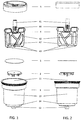
- Figs. 1 and 2 show exploded views of a capsule according to an embodiment of the present invention, wherein Fig. 1 is a perspective view, and Fig. 2 is a side view on the different elements of the capsule.
- a housing 1 of the capsule comprises an inlet 11 and an outlet 12.
- a side of the housing 1 on which the outlet 12 is located shall be defined as bottom side.
- the housing 1 is cylindrical and/or conical in shape, and made of plastic or aluminium. Material and shape of the housing 1 preferably ensure a good storage quality of the powder, and to sustain pressures occurring during a preparation of the beverage.
- the housing 1 comprises a cavity 13 for containing powder for preparing a beverage.
- a bottom of the cavity 13 is formed by an inner membrane 3, which preferably is an aluminium or metal foil, and preferably is glued into the housing 1.
- the inner membrane 3 separates the cavity 13 from another cavity 14 located between the inner membrane 3 and the outlet 12.
- the other cavity 14 is empty when the capsule is in a first state characterized by the inner membrane 3 being intact, i.e. the outlet 12 being closed.
- insert 2 Inside the other cavity 14, there is an insert 2, preferably also made from plastic.
- the insert 2 acts as a support for the inner membrane 3, and protects it from being damaged while the capsule is in the first state.
- the insert 2 is formed in such a way as to improve a mixing of the powder and water, when a mixture is flowing through the other cavity towards the outlet in a second state of the capsule, which second state is defined by the inner membrane 3 being cut and/or pierced, i.e. the outlet 12 being open.
- a shape of the insert 2 may also contribute to forming a laminar outflow from the outlet, hence making the beverage more appealing for a user.
- the agitator 4 comprises a central shaft 41 for coupling to an external motor.
- the central shaft 41 comprises coupling means 44, which enable reversible coupling to a motor shaft.
- the agitator 4 comprises at least one blade 42 attached to the central shaft 41.
- a blade 42 is a laminar element extending radially outward from the central shaft 41
- the agitator 4 shown in Figs. 1 and 2 comprises two blades 42 and 42' with an angular offset of 180°.
- the blades 42, 42' comprise a frame and several bars forming a lattice structure.
- the lattice structure differs between the first blade 42 and the second blade 42', hence making the agitator 4 asymmetric.
- the lattice structure of the blades 42, 42' makes rotating the agitator 4 in the powder easier, while the asymmetry leads to an improved wetting and mixing of powder with water, especially during premixing when the capsule is in the first state.
- the blades 42, 42' comprise blade elements 43 for piercing and/or cutting the inner membrane 3, transferring the capsule to the second state.
- the central shaft 41 is pivoted in a bearing 5 comprised in the capsule.
- the bearing 5 may include a ring, preferably made from plastic, fixed in the upper part of the housing 1.
- the bearing 5 is configured to allow rotation as well as an axial shift of the central shaft 41 between an upper and a lower axial position.
- the axial shift of the agitator 4 enables controlling different operating steps, namely a premixing step, an opening step, and a mixing step.
- the states of the capsule as well as the different operation phases may be understood in more detail from Figs. 3 and 4 .
- Fig. 3 shows a cut through a capsule according to an embodiment of the present invention.
- the capsule again comprises a housing 1 with an inlet 11, an outlet 12, a cavity 13 for containing powder, and a second cavity 14 with an insert 2 below an inner membrane 3.
- the capsule comprises an agitator 4 pivoted in a bearing 5, and a top membrane 6.
- the top membrane 6 seals the inlet 11, is preferably an aluminium or plastic foil, and typically is sealed or glued or welded onto the housing 1.
- the capsule is inserted into a capsule holder of a corresponding apparatus.
- the top membrane 6 is pierced by one or more injection needles of the apparatus, located e.g. at half radius of the top membrane 6.
- the central shaft 41 of the agitator 4 is coupled to the motor shaft of the apparatus, while the agitator 4 stays in the upper axial position.
- water is supplied into the capsule, and the agitator 4 is rotated, while the capsule is still in the first state, i.e. the cavity 13 is sealed against the outlet 12. It is advantageous that the rotation during premixing is performed stepwise, and in both directions backward and forward, in order to achieve sufficient wetting of the powder.
- the agitator 4 is shifted axially to the lower axial position, which results in a piercing of the inner membrane 3 through the blade elements 43. If the agitator 4 is rotated at the same time, the inner membrane 3 is rather cut than pierced, and a circular passage is formed between the cavity 13 originally containing the powder and the originally empty other cavity 14. It is advantageous that the agitator 4 rotates at a high speed, e.g. 100 to 1000 rpm, and in particular 500 rpm, already before the axial shifting, in order to achieve a reliable and clean cutting. Also, it is preferred to repeat the axial shift of the agitator 4 to ensure that the inner membrane 3 is actually cut. After cutting, the capsule is in the second state, i.e. the outlet is open.
- the mixing step more water is supplied into the capsule and the agitator 4 rotates at high speed. In that way, powder and water are well mixed, and flow as a homogeneous solution through the other cavity 14 and the outlet 12 into a drinking container, such as a glass or a bottle. As a result, the capsule is emptied from the powder to a high degree, and the user is provided with an appetizing beverage in the drinking container.
- Fig. 4 displays a diagram of certain parameters over time in seconds implementing a method according to an aspect of the present invention.
- the displayed parameters are an angular position S1 of the agitator 4 during a first time interval, a rotation speed S2 of the agitator 4 during a later time interval, a switching of the water supply S3, and an axial position of the agitator S4.
- the method comprises three main steps: premixing (a), opening (b), and mixing (c), wherein the opening and mixing steps (b) and (c) may overlap.
- a first interval (a1) of premixing (a) water is supplied into the capsule in a pulsed manner, see parameter S3.
- the total amount of water supplied during the first interval (a1) of the premixing step (a) is limited by a volume of the cavity 13 and an amount of powder contained in the cavity 13.
- the agitator 4 is rotated forward, preferably only for a half or a full turn, also in a pulsed manner, see parameter S1. While the pulses of supplied water continue, the agitator 4 is rotated backward and forward in a pulsed manner. Following this procedure improves a wetting of the powder by creating new pathways for the water, resulting in a well wetted, viscous predough.
- the agitator 4 starts rotating continuously in one direction at a high speed, e.g. at 500 rpm, see parameter S2, making the predough more homogeneous, while in this second interval (a2) no more water is supplied, see parameter S3.
- the opening step (b) begins with an axial shift of the agitator 4 from the upper to the lower axial position, see parameter S4. At high rotation speed, the agitator 4 then pierces and cuts the inner membrane 3, thus opening a passage for the mixture to the outlet 12. In consequence, the mixture gradually flows out from the capsule. According to Fig. 4 , the axial downward shift is repeated once before returning to the upper axial position, which ensures reliable cutting of the inner membrane 3.
- the mixing step (c) starts when the inner membrane 3 is cut, and the mixture is free to flow out of the capsule.
- the mixing step (c) more water is supplied continuously into the capsule, see parameter S3, while the agitator rotates at high speed, see parameter S2. This leads to a high degree of drainage of the capsule and only little amounts of wasted powder.
- the entire preparation time can be estimated from the time scale in seconds.
- the duration of the individual steps are preferred variants only, and vary subject to the powder used, or subject to other parameters.
Landscapes
- Engineering & Computer Science (AREA)
- Mechanical Engineering (AREA)
- Food Science & Technology (AREA)
- Chemical & Material Sciences (AREA)
- Chemical Kinetics & Catalysis (AREA)
- Dispersion Chemistry (AREA)
- Apparatus For Making Beverages (AREA)
- Food-Manufacturing Devices (AREA)
Description
- The present invention relates to a capsule for preparing a beverage. Further aspects of the invention concern an apparatus and a method for preparing a beverage.
- Conventional ways of preparing beverages from powders, such as sports drinks, energy drinks, soups, or baby formula, are delicate since they require significant amounts of time and attention to measure a right quantity of powder, to transfer the powder to a glass or bottle without spilling, to mix the powder sufficiently with water, and to clean any equipment used. Moreover quality and solubility of the powder usually decrease with a time a powder container has been open for. Hence the conventional preparation of beverages from powder is on the one hand inconvenient, and on the other hand, it rarely yields desirable results in terms of a homogeneous solution of the powder in water.
- Existing improvements comprise prepackaged portions of powder in bags or capsules. However, some drawbacks persist, in particular undesired spilling, cleaning, and reaching a homogeneous mixture.
- It is desired that the preparation of a beverage from powder is easy and quick, and that it yields a homogeneous solution and an appetizing drink, respectively.
-
WO 2015/032787 A1 describes a capsule and a system of food or beverage production machine and a capsule, wherein the capsule has an integrated mixing unit, which can be moved and/or rotated in respect to a capsule body. By rotating the mixing unit, beverage or food product ingredients inside the capsule are mixed with a liquid introduced into the capsule. The rotation of the mixing unit further generates a pressure, which pushes the produced beverage or food product through a capsule outlet. The rotation of the mixing unit can also move the mixing unit between a first position and a second position, in order to selectively open or close the outlet of the capsule. - The problem to be solved by the present invention is to provide a capsule and a method for preparing a beverage, which overcomes the disadvantages and limitations of the conventional ways of preparing of a beverage from powder.
- The problem is solved by a capsule for preparing a beverage, comprising a housing with an outlet, and a cavity for containing a powder, an inner membrane between the cavity and the outlet, an agitator, comprising a central shaft, and at least one blade attached to the central shaft. The at least one blade comprises at least one blade element for piercing and/or cutting the inner membrane.
- In different embodiments, the capsule may be a container of cylindrical or conical or cuboid or mixed outer shape. The housing may be manufactured as one part, or composed of several parts. Beverages may be, but are not restricted to sports drinks, energy drinks, soups, or baby formula. Powders for preparing the beverage comprise all kinds of granular matter. In other embodiments, the powder may be on hand as a solution, a viscous fluid or a gel.
- The capsule comprises an inner membrane between the cavity and the outlet for sealing any powder contained in the cavity in a first state, in which the inner membrane is intact, i.e. the outlet is closed against the cavity. The inner membrane may prevent air contact of the powder in the first state, or it may result in a vacuum pack of the powder, such that properties of the powder for storage are improved, and taste and quality are preserved. In different embodiments, the cavity may contain the powder and air, or may contain the powder and a different gas. Preferably, the inner membrane is arranged inside the capsule at an axial level of the capsule different from the axial level of the outlet. Hence, it is preferred that the outlet itself is not sealed, but the outlet is sealed against the cavity by means of the inner membrane being arranged in the capsule offset from the outlet.
- According to the invention, the agitator comprises one or several blades attached to the central shaft, including the one or several blades and the central shaft being formed as one piece The central shaft is in particular used to contact the agitator from outside the capsule, e.g. by a motor shaft of a corresponding apparatus for preparing beverages. For that purpose, the central shaft may comprise coupling means for reversible attachment to the motor shaft. The central shaft may have a length corresponding to an inner height of the cavity, or it may in particular have a length smaller than the inner height of the cavity.
- A blade of the agitator shall be defined as a laminar element, which extends predominantly vertically, i.e. axially along the central shaft, and radially outward from the central shaft. A blade may be a continuous laminar element, or it may in particular be made of a lattice structure, e.g. a frame with bars reaching from one side of the frame to a different side.
- The blade element for piercing and/or cutting the inner membrane may be part of, or attached to the blade, alternatively. In a different embodiment it may be attached to any part of the agitator. The blade element may e.g. be a spike, a stud, or a knife, configured to pierce and/or cut the inner membrane, when pushed onto, or dragged along the latter.
- When rotated, the agitator mixes or stirs the powder in the cavity. In particular, it is used for premixing the powder with any supplied water in a first state while the inner membrane still is intact. The agitator may also be used to pierce and/or cut the inner membrane, transferring the capsule to a second state, in which a mixture of water and powder may pour from the cavity through the piercings or the slots in the inner membrane to the outlet, and finally out of the outlet. The piercing or cutting may be effected by an axial movement of the agitator, which may be accompanied by a rotation of the agitator. As a result, the mixture of powder and water may flow out of the capsule via the outlet, while the agitator may be used to mix the remaining powder with more water. In this way, a good mixture and a homogeneous solution of powder and water is achieved. Moreover, rotating the agitator makes a high flow rate feasible as well as a high degree of drainage of the capsule, resulting in a good recovery rate and less wasted powder, and causing less spilling when discarding the capsule.
- To further improve the mixing properties of the agitator, it may preferably comprise at least two blades which differ from each other in shape. In an embodiment, two blades may be arranged on opposite sides of the central shaft, i.e. with an angular offset of 180°. In particular the at least two blades may have differing lattice structures, forming an asymmetric agitator. Such asymmetry has the effect that the frame and the bars of the blades run along different trajectories, when the agitator is rotated, thus creating multiple pathways in the mixture, resulting in a better wetting and mixing.
- Preferably the capsule comprises a top membrane for sealing an inlet of the housing. The inlet may be an opening in the side of the housing situated opposite to the outlet. Preferably, the powder is filled into the cavity of the capsule through the inlet of the capsule prior to the inlet being sealed by the top membrane, e.g. at a manufacturing site. The side of the outlet is defined as the bottom side, the side of the inlet as the top side. The top membrane may be glued on the housing, and prevent any contact with air or liquid or any other contamination of the powder. When preparing the beverage, the top membrane may be pierced or cut or peeled off, in order to supply water into the capsule.
- Further the capsule preferably comprises a bearing for the central shaft of the agitator. The bearing is configured to enable a shift of the agitator between an upper and a lower axial position. In particular a top end of the central shaft located next to the inlet is pivotable in the bearing. The bearing keeps the central shaft in place, especially when the capsule is transported, or when the agitator is rotated. Due to the possibility of axial shifting, the agitator can be used to open the outlet by cutting and/or piercing the inner membrane. In a different embodiment, the combination of agitator and bearing may be arranged and configured shiftable in axial direction, e.g. in form of a movement relative the housing of the capsule.
- Hence, the agitator and the bearing for the agitator are arranged in the capsule, and preferably are arranged in the cavity of the capsule. Such capsule, when being distributed, may include the agitator, the bearing and the powder inside the cavity of the capsule. The cavity preferably is sealed by means of the inner membrane against the otherwise open outlet of the capsule, while the inlet of the capsule and hence the cavity is sealed by the top membrane.
- Preferably the housing comprises another cavity between the inner membrane and the outlet. In that way, the inner membrane is not located directly at the outlet, and hence is protected against unwanted damaging. Moreover, the other cavity improves the mixing properties, and leads to a laminar outflow from the outlet.
- Further the capsule preferably comprises an insert in the other cavity. The insert is configured to enable pivoting of a bottom end of the agitator located next to the outlet, when the agitator is in a lower axial position. Thus it stabilizes the rotation of the agitator, especially when the latter is cutting the inner membrane. In particular the insert is configured to prevent piercing of the inner membrane, when the agitator is in an upper axial position. Besides it further improves the mixing properties of the other cavity.
- The cavity is preferably configured to contain at least 15 g of powder for preparing a beverage, in particular 25 to 50 g of powder, which is a typical amount for one portion or serving. The amount of powder in the capsule may vary depending on the type of beverage prepared. The amount of resulting beverage may typically be in a range between 2 and 3 dl, preferably 2.5 dl.
- One or more of the housing, the agitator, the insert, and the bearing are preferably made of plastic or aluminium. The inner membrane and/or the top membrane are preferably a plastic foil or an aluminium foil. It is preferred that the materials preserve taste and quality of the powder during storage.
- Preferably the capsule also comprises a bypass for water to flow through the capsule without coming into contact with the powder. The bypass may have a bypass inlet on the top side of the capsule for connecting to a water supply. The bypass bypasses the cavity with the powder, and it may comprise a bypass outlet at the bottom side of the capsule, which may coincide with the outlet of the capsule. The bypass facilitates leading an amount of pure water without powder into a drinking container, which can improve a resulting beverage in terms of mixing and appetizing appearance, in particular when applied before cutting the inner membrane.
- In a different embodiment, instead of the bypass integrated into the capsule, the bypass may be provided as an element of the apparatus to be introduced below. Again, the bypass, e.g. in form of a tube, allows water from a water supply of the apparatus to pour directly into the drinking container without passing the capsule. Again preferably, such water supply may preferably be applied before the inner membrane is cut, for the very purposes as laid out above.
- According to an aspect of the invention, the capsule is complemented with an apparatus for preparing a beverage. The apparatus comprises a capsule holder configured to receive a capsule as described above, a water supply configured to supply water to the capsule, a motor configured to drive the agitator of the capsule, and a control unit configured to control the water supply and the motor. In particular the water supply may comprise one or more injection needles configured to pierce the top membrane of the capsule and supply water into the cavity of the capsule.
- In different embodiments, the capsule holder may be a drawer in which a user inserts the capsule and then closes the drawer, or it may be a receptacle which can be closed, e.g. through pressing a lever. Preferably an inner shape of the capsule holder fits an outer shape of the capsule.
- The water supply may be fed by a water tank of the apparatus, or it may be fed via a connection with a water pipe. Preferably, the water supply comprises pumping and measuring means, and is controlled by the control unit, in order to supply a correct amount of water into the capsule. The motor may be an electric motor with speed and sense of rotation being controlled by the control unit.
- Preferably the motor is configured to drive a motor shaft, which is configured to couple to the central shaft of the agitator. In an embodiment, the motor shaft may comprise coupling means for reversibly coupling to the central shaft of the agitator. The coupling may be achieved by a vertical movement of the motor shaft, e.g. by pressing a lever, which may be the lever mentioned above closing the capsule holder or lowering the injection needle at the same time.
- The motor shaft, or the motor shaft and the motor are preferably shiftable in an axial direction between an upper and a lower axial position, and in particular the shift between the upper and the lower axial position is controlled by the control unit. In different embodiments, the axial shift is caused hydraulically or through an electric servo motor. In that way, the axial shift, being responsible for a piercing and/or cutting of the inner membrane, is performed in a precise and controlled manner.
- Further the apparatus preferably comprises an indicator light and one or more control buttons and/or other I/O interface means such as a GUI. The indicator light may e.g. be an LED, indicating different operating states of the apparatus through different lighting patterns or colours. The control button is envisaged to be a one-button-control for the apparatus, enabling the performance of all required user interaction by touching or pressing this one button only. A performance of a desired action may e.g. depend on a duration of touching the button.
- In case the capsule comprises a bypass, the apparatus preferably also contains a bypass water supply. The bypass water supply couples to the bypass inlet, when the capsule is inserted into the capsule holder. Also the bypass water supply is preferably controlled by the control unit.
- According to another aspect of the invention, a method for preparing a beverage comprises the steps of (a) premixing a powder and water inside a cavity of a capsule, while an outlet of the capsule is sealed against the cavity by an inner membrane, (b) piercing and/or cutting the inner membrane previously sealing the outlet, and (c) mixing the powder and more water inside the capsule, when the outlet is accessible from the cavity, a resulting mixture flowing out from the outlet. This means steps (a) and (c) are conditional on the state (closed/open) of the outlet, previously referred to as the first and the second state of the capsule, i.e. the inner membrane being intact and pierced or cut, respectively. Opening the outlet in step (b) transfers the capsule from the first to the second state.
- Performing the method as described with a premixing step (a) significantly improves mixing results. This can be understood in analogy to kneading a predough with only a little amount of liquid, which increases a wetting of the powder and avoids a forming of lumps. Thus the resulting beverage is more homogeneous and more appetizing.
- The premixing step (a) preferably comprises the steps of piercing a top membrane of the capsule sealing an inlet of the cavity by an injection needle and supplying water into the cavity of the capsule, and premixing the powder and the water inside the cavity through a forward and backward rotation of an agitator comprised in the cavity. In particular the supply of water and the rotation may be performed intermittently, and simultaneously or alternatingly. In an embodiment, the injection needle is part of the apparatus, and may be moved vertically by user interaction through pressing a lever, or it may be moved hydraulically or by a servo motor. An amount of water supplied during the premixing step (a) is limited by a volume of a cavity inside the capsule containing the powder. The forward and backward rotation being performed stepwise and repeatedly improve the distribution of the water as well as the wetting of the powder.
- The cutting and/or piercing step (b) comprises the step of piercing and/or cutting an inner membrane of the capsule with a blade element attached to the agitator through an axial movement of the agitator from an upper to a lower axial position and a simultaneous rotation of the agitator, as described above with respect to the capsule and the apparatus. In particular the axial movement may be reversed and repeated, which improves a cutting result, and makes sure that the inner membrane is actually cut and the outlet is open, even in case of a failure at a first try.
- The mixing step (c) preferably comprises the steps of supplying more water into the capsule, and mixing the powder and the more water inside the capsule through a rotation of the agitator, which rotation is faster than a rotation in the premixing step (a). During the mixing step (c), water may be supplied continuously. In connection with the rotation of the agitator, this leads to a high degree of drainage of the capsule and only small amounts of wasted powder. For that purpose, the rotation in the mixing step (c) may spin the agitator at 100 to 1000 rpm, and in particular at 500 rpm.
- In an embodiment, an additional bypass water supply step may be intercalated before the premixing step (a). In the bypass water supply step, water is supplied directly into the drinking container without being in contact with the powder. In different embodiments, the water may flow through a bypass in the capsule before it enters the drinking container, or it may directly be supplied from the apparatus into the drinking container. The bypass water supply step was found to increase mixing results and homogeneity of the resulting beverage.
- The embodiments defined above and further aspects, features and advantages of the present invention can also be derived from the examples of embodiments to be described hereinafter and are explained with reference to the drawings. In the drawings, it is illustrated in
-
Fig. 1 a perspective exploded view of a capsule according to an embodiment of the present invention, -
Fig. 2 another exploded view of the capsule according to an embodiment of the present invention, -
Fig. 3 a cut through a capsule according to an embodiment of the present invention, -
Fig. 4 a diagram of certain parameters over time implementing a method according to an aspect of the present invention. -
Figs. 1 and 2 show exploded views of a capsule according to an embodiment of the present invention, whereinFig. 1 is a perspective view, andFig. 2 is a side view on the different elements of the capsule. - A
housing 1 of the capsule comprises aninlet 11 and anoutlet 12. A side of thehousing 1 on which theoutlet 12 is located shall be defined as bottom side. Preferably thehousing 1 is cylindrical and/or conical in shape, and made of plastic or aluminium. Material and shape of thehousing 1 preferably ensure a good storage quality of the powder, and to sustain pressures occurring during a preparation of the beverage. - The
housing 1 comprises acavity 13 for containing powder for preparing a beverage. A bottom of thecavity 13 is formed by aninner membrane 3, which preferably is an aluminium or metal foil, and preferably is glued into thehousing 1. Theinner membrane 3 separates thecavity 13 from anothercavity 14 located between theinner membrane 3 and theoutlet 12. Theother cavity 14 is empty when the capsule is in a first state characterized by theinner membrane 3 being intact, i.e. theoutlet 12 being closed. - Inside the
other cavity 14, there is aninsert 2, preferably also made from plastic. Theinsert 2 acts as a support for theinner membrane 3, and protects it from being damaged while the capsule is in the first state. Moreover theinsert 2 is formed in such a way as to improve a mixing of the powder and water, when a mixture is flowing through the other cavity towards the outlet in a second state of the capsule, which second state is defined by theinner membrane 3 being cut and/or pierced, i.e. theoutlet 12 being open. A shape of theinsert 2 may also contribute to forming a laminar outflow from the outlet, hence making the beverage more appealing for a user. - Inside the
cavity 13, there is anagitator 4, preferably also made from plastic. Theagitator 4 comprises acentral shaft 41 for coupling to an external motor. Preferably thecentral shaft 41 comprises coupling means 44, which enable reversible coupling to a motor shaft. - Further the
agitator 4 comprises at least oneblade 42 attached to thecentral shaft 41. According to the definition that ablade 42 is a laminar element extending radially outward from thecentral shaft 41, theagitator 4 shown inFigs. 1 and 2 comprises twoblades 42 and 42' with an angular offset of 180°. Theblades 42, 42' comprise a frame and several bars forming a lattice structure. The lattice structure differs between thefirst blade 42 and the second blade 42', hence making theagitator 4 asymmetric. The lattice structure of theblades 42, 42' makes rotating theagitator 4 in the powder easier, while the asymmetry leads to an improved wetting and mixing of powder with water, especially during premixing when the capsule is in the first state. - The
blades 42, 42' compriseblade elements 43 for piercing and/or cutting theinner membrane 3, transferring the capsule to the second state. For that purpose, thecentral shaft 41 is pivoted in abearing 5 comprised in the capsule. Thebearing 5 may include a ring, preferably made from plastic, fixed in the upper part of thehousing 1. Thebearing 5 is configured to allow rotation as well as an axial shift of thecentral shaft 41 between an upper and a lower axial position. The axial shift of theagitator 4 enables controlling different operating steps, namely a premixing step, an opening step, and a mixing step. The states of the capsule as well as the different operation phases may be understood in more detail fromFigs. 3 and 4 . -
Fig. 3 shows a cut through a capsule according to an embodiment of the present invention. The capsule again comprises ahousing 1 with aninlet 11, anoutlet 12, acavity 13 for containing powder, and asecond cavity 14 with aninsert 2 below aninner membrane 3. Further the capsule comprises anagitator 4 pivoted in abearing 5, and atop membrane 6. Thetop membrane 6 seals theinlet 11, is preferably an aluminium or plastic foil, and typically is sealed or glued or welded onto thehousing 1. - For preparing a beverage, the capsule is inserted into a capsule holder of a corresponding apparatus. The
top membrane 6 is pierced by one or more injection needles of the apparatus, located e.g. at half radius of thetop membrane 6. Preferably at the same time, thecentral shaft 41 of theagitator 4 is coupled to the motor shaft of the apparatus, while theagitator 4 stays in the upper axial position. For premixing, water is supplied into the capsule, and theagitator 4 is rotated, while the capsule is still in the first state, i.e. thecavity 13 is sealed against theoutlet 12. It is advantageous that the rotation during premixing is performed stepwise, and in both directions backward and forward, in order to achieve sufficient wetting of the powder. - In the opening step, the
agitator 4 is shifted axially to the lower axial position, which results in a piercing of theinner membrane 3 through theblade elements 43. If theagitator 4 is rotated at the same time, theinner membrane 3 is rather cut than pierced, and a circular passage is formed between thecavity 13 originally containing the powder and the originally emptyother cavity 14. It is advantageous that theagitator 4 rotates at a high speed, e.g. 100 to 1000 rpm, and in particular 500 rpm, already before the axial shifting, in order to achieve a reliable and clean cutting. Also, it is preferred to repeat the axial shift of theagitator 4 to ensure that theinner membrane 3 is actually cut. After cutting, the capsule is in the second state, i.e. the outlet is open. - During the mixing step, more water is supplied into the capsule and the
agitator 4 rotates at high speed. In that way, powder and water are well mixed, and flow as a homogeneous solution through theother cavity 14 and theoutlet 12 into a drinking container, such as a glass or a bottle. As a result, the capsule is emptied from the powder to a high degree, and the user is provided with an appetizing beverage in the drinking container. -
Fig. 4 displays a diagram of certain parameters over time in seconds implementing a method according to an aspect of the present invention. The displayed parameters are an angular position S1 of theagitator 4 during a first time interval, a rotation speed S2 of theagitator 4 during a later time interval, a switching of the water supply S3, and an axial position of the agitator S4. The method comprises three main steps: premixing (a), opening (b), and mixing (c), wherein the opening and mixing steps (b) and (c) may overlap. - In a first interval (a1) of premixing (a), water is supplied into the capsule in a pulsed manner, see parameter S3. The total amount of water supplied during the first interval (a1) of the premixing step (a) is limited by a volume of the
cavity 13 and an amount of powder contained in thecavity 13. Theagitator 4 is rotated forward, preferably only for a half or a full turn, also in a pulsed manner, see parameter S1. While the pulses of supplied water continue, theagitator 4 is rotated backward and forward in a pulsed manner. Following this procedure improves a wetting of the powder by creating new pathways for the water, resulting in a well wetted, viscous predough. In a subsequent second interval (a2) of the premixing (a), theagitator 4 starts rotating continuously in one direction at a high speed, e.g. at 500 rpm, see parameter S2, making the predough more homogeneous, while in this second interval (a2) no more water is supplied, see parameter S3. - The opening step (b) begins with an axial shift of the
agitator 4 from the upper to the lower axial position, see parameter S4. At high rotation speed, theagitator 4 then pierces and cuts theinner membrane 3, thus opening a passage for the mixture to theoutlet 12. In consequence, the mixture gradually flows out from the capsule. According toFig. 4 , the axial downward shift is repeated once before returning to the upper axial position, which ensures reliable cutting of theinner membrane 3. - By definition, the mixing step (c) starts when the
inner membrane 3 is cut, and the mixture is free to flow out of the capsule. During the mixing step (c), more water is supplied continuously into the capsule, see parameter S3, while the agitator rotates at high speed, see parameter S2. This leads to a high degree of drainage of the capsule and only little amounts of wasted powder. - The entire preparation time can be estimated from the time scale in seconds. The duration of the individual steps are preferred variants only, and vary subject to the powder used, or subject to other parameters.
Claims (15)
- Capsule for preparing a beverage, comprising- a housing (1) with an outlet (12), and a cavity (13) for containing a powder,- an agitator (4), comprising a central shaft (41), and at least one blade (42) attached to the central shaft (41),
characterized by- an inner membrane (3) between the cavity (13) and the outlet (12),
the at least one blade (42) comprising at least one blade element (43) for piercing and/or cutting the inner membrane (3). - Capsule according to claim 1, the agitator (4) comprising at least two blades (42, 42') which differ from each other in shape,
in particular the at least two blades (42, 42') having differing lattice structures. - Capsule according to any of the preceding claims, comprising a top membrane (6) for sealing an inlet (11) of the housing (1).
- Capsule according to any of the preceding claims, comprising a bearing (5) for the central shaft (41) of the agitator (4), the bearing (5) being configured to enable a shift of the agitator (4) between an upper and a lower axial position,
in particular a top end of the central shaft (41) located next to the inlet (11) being pivotable in the bearing (5). - Capsule according to any of the preceding claims, the housing (1) comprising another cavity (14) between the inner membrane (3) and the outlet (12).
- Capsule according to claim 5, comprising an insert (2) in the other cavity (14),
the insert (2) being configured to enable pivoting of a bottom end of the agitator (4) located next to the outlet (12), when the agitator (4) is in a lower axial position, and
in particular the insert (2) being configured to prevent piercing of the inner membrane (3), when the agitator (4) is in an upper axial position. - Capsule according to any of the preceding claims, the cavity (13) being configured to contain at least 15 g of powder for preparing a beverage,
in particular 25 to 50 g of powder. - Capsule according to any of the preceding claims, one or more of the housing (1), the agitator (4), the insert (2), and the bearing (5) being made of plastic.
- Capsule according to any of the preceding claims, the inner membrane (3) and/or the top membrane (6) being a plastic foil or an aluminium foil.
- Apparatus for preparing a beverage, comprising- a capsule holder holding a capsule according to any of the preceding claims,- a water supply configured to supply water to the capsule,- a motor configured to drive the agitator (4) of the capsule, and- a control unit configured to control the water supply and the motor,
in particular the water supply comprising an injection needle configured to pierce the top membrane (6) of the capsule and supply water into the cavity (13) of the capsule. - Apparatus according to claim 10, the motor being configured to drive a motor shaft, which is configured to couple to the central shaft (41) of the agitator (4),
the motor shaft, or the motor shaft and the motor being shiftable in an axial direction between an upper and a lower axial position,
in particular the shift between the upper and the lower axial position being controlled by the control unit. - Method for preparing a beverage, comprising the steps of(a) premixing a powder and water inside a cavity (13) of a capsule, while an outlet (12) of the capsule is sealed against the cavity (13) by an inner membrane (3),(b) piercing and/or cutting the inner membrane (3) previously sealing the outlet (12), and(c) mixing the powder and more water inside the capsule, when the outlet (12) is accessible from the cavity (13), a resulting mixture flowing out from the outlet (12),wherein the opening step (b) comprises the step of cutting the inner membrane (3) with a blade element (43) attached to an agitator (4) through an axial movement of the agitator (4) from an upper to a lower axial position and a simultaneous rotation of the agitator (4) .
- Method according to claim 12, the premixing step (a) comprising the steps of- piercing a top membrane (6) of the capsule sealing an inlet (11) of the capsule by an injection needle and supplying water into the cavity (13), and- premixing the powder and the water inside the cavity (13) through a forward and backward rotation of an agitator (4) comprised in the capsule,
in particular the supply of water and the rotation being performed intermittently, and simultaneously or alternatingly. - Method according to claims 12 or 13,
the axial movement in the opening step (b) being reversed and repeated. - Method according to any of claims 12 to 14, the mixing step (c) comprising the step of- supplying more water into the capsule, and mixing the powder and the more water inside the capsule through a rotation of the agitator (4), which rotation is faster than a rotation in the premixing step (a),
in particular the rotation in the mixing step (c) spinning the agitator (4) at 100 to 1000 rpm, in particular at 500 rpm.
Priority Applications (4)
| Application Number | Priority Date | Filing Date | Title |
|---|---|---|---|
| DK18159995.2T DK3536637T3 (en) | 2018-03-05 | 2018-03-05 | Capsule for making a beverage |
| EP18159995.2A EP3536637B1 (en) | 2018-03-05 | 2018-03-05 | Capsule for preparing a beverage |
| US16/291,816 US11273975B2 (en) | 2018-03-05 | 2019-03-04 | Capsule for preparing a beverage |
| CN201910163245.9A CN110226878B (en) | 2018-03-05 | 2019-03-05 | Capsule for preparing a beverage |
Applications Claiming Priority (1)
| Application Number | Priority Date | Filing Date | Title |
|---|---|---|---|
| EP18159995.2A EP3536637B1 (en) | 2018-03-05 | 2018-03-05 | Capsule for preparing a beverage |
Publications (2)
| Publication Number | Publication Date |
|---|---|
| EP3536637A1 EP3536637A1 (en) | 2019-09-11 |
| EP3536637B1 true EP3536637B1 (en) | 2020-09-16 |
Family
ID=61569106
Family Applications (1)
| Application Number | Title | Priority Date | Filing Date |
|---|---|---|---|
| EP18159995.2A Active EP3536637B1 (en) | 2018-03-05 | 2018-03-05 | Capsule for preparing a beverage |
Country Status (4)
| Country | Link |
|---|---|
| US (1) | US11273975B2 (en) |
| EP (1) | EP3536637B1 (en) |
| CN (1) | CN110226878B (en) |
| DK (1) | DK3536637T3 (en) |
Families Citing this family (7)
| Publication number | Priority date | Publication date | Assignee | Title |
|---|---|---|---|---|
| US8960999B1 (en) | 2014-03-28 | 2015-02-24 | Gudpod Holdings, Llc | System for mixing beverages and method of doing the same |
| CH714474A1 (en) * | 2017-12-20 | 2019-06-28 | Muehlemann Ip Gmbh | Capsule with integrated dispenser. |
| CN112191140B (en) * | 2020-09-17 | 2022-08-19 | 王顿 | Food capsule, stirring device and food capsule using method |
| GB202105761D0 (en) * | 2021-04-22 | 2021-06-09 | Ne Innovations Ltd | Pod for beverage preparation ingredient |
| WO2024235473A1 (en) | 2023-05-17 | 2024-11-21 | Nootrie Ag | Reclosable capsule for preparing a beverage |
| CN121398723A (en) | 2023-05-17 | 2026-01-23 | 努特里股份公司 | Apparatus and method for preparing a mixture in a capsule |
| CN121633423A (en) * | 2026-02-04 | 2026-03-10 | 山西万家寨引黄水务集团有限公司 | An automatic calibration device and method for online water quality monitoring sensors |
Family Cites Families (86)
| Publication number | Priority date | Publication date | Assignee | Title |
|---|---|---|---|---|
| AT283183B (en) | 1968-11-02 | 1970-07-27 | Kantor Internat S A | Capsule for containing substances intended for the preparation of beverages |
| ES2286112T3 (en) | 2001-03-23 | 2007-12-01 | Tuttoespresso S.P.A. | UNIT FOR THE PREPARATION OF BEVERAGES FROM SOLUBLE PRODUCTS. |
| EP2241229B8 (en) | 2001-04-27 | 2012-07-25 | Mars, Incorporated | Beverage apparatus for making foamed drinks |
| ITTO20010902A1 (en) * | 2001-09-21 | 2003-03-21 | Sgl Italia Srl | COFFEE MACHINE'. |
| ES2275874T3 (en) | 2002-04-30 | 2007-06-16 | BORMIOLI ROCCO & FIGLIO S.P.A. | CAPSULE CONTAINING A SUBSTANCE TO MIX IN BOTTLES CONTAINING PRESSURIZED LIQUIDS. |
| US6955461B2 (en) * | 2003-01-24 | 2005-10-18 | Dow Global Technologies, Inc. | Tickler for slurry reactors and tanks |
| BRPI0407994A (en) | 2003-03-03 | 2006-03-07 | Procter & Gamble | liquid infusion pouches containing insoluble materials |
| ATE529027T1 (en) | 2003-08-25 | 2011-11-15 | Nestec Sa | METHOD AND DEVICE FOR PRODUCING A BEVERAGE FROM A CAPSULE CONTAINING A SUBSTANCE |
| EP1510159A1 (en) | 2003-08-25 | 2005-03-02 | Nestec S.A. | Procedure for making a food product |
| GB2406329A (en) * | 2003-09-29 | 2005-03-30 | Mars Inc | Apparatus for making multiple beverages with reduced cross-contamination |
| DE502005003579D1 (en) | 2004-06-14 | 2008-05-15 | Mathias Och | DEVICE FOR PREPARING SMALL-CHICKEN FOOD |
| US9242791B2 (en) | 2004-08-23 | 2016-01-26 | Nestec S.A. | Capsule for preparing and delivering a drink by injecting a pressurized fluid into the capsule |
| CN101056802B (en) * | 2004-09-17 | 2011-02-09 | 图托埃布莱束股份公司 | Disposable capsule for drinks and its opening method |
| EP1785369A1 (en) * | 2005-11-10 | 2007-05-16 | Nestec S.A. | Beverage ingredient containing capsule having several compartments |
| ITMO20070143A1 (en) | 2007-04-27 | 2008-10-28 | Massimiliano Pineschi | CAPSULE TO CONTAIN DOSAGES OF SOLUBLE BEVERAGES |
| EP2155019B1 (en) * | 2007-06-05 | 2011-04-06 | Nestec S.A. | Method for preparing a beverage or liquid food |
| ATE476123T1 (en) * | 2008-01-18 | 2010-08-15 | Nestec Sa | DRINKS MACHINE AND PIERCING PART FOR AN OPENING DEVICE OF A DRINKS MACHINE |
| ATE506292T1 (en) | 2008-02-06 | 2011-05-15 | Nestec Sa | LABYRINTH CAPSULE FOR DRINK POWDER |
| US8177418B2 (en) * | 2008-03-06 | 2012-05-15 | Debra Edwards | Apparatus for making, storing, and transporting frozen confections and method |
| CN101969823B (en) | 2008-03-14 | 2013-05-29 | 摩考菲股份公司 | Apparatus and capsule for making a drink |
| PT2280885E (en) | 2008-04-30 | 2014-02-12 | Nestec Sa | Sealed capsule for containing beverage ingredients and having an inlet-side membrane |
| US9750370B2 (en) * | 2009-05-29 | 2017-09-05 | Keurig Green Mountain, Inc. | Cartridge with filter guard |
| RU2534058C2 (en) * | 2009-06-17 | 2014-11-27 | Конинклейке Дауве Егбертс Б.В., Nl | System, method and capsule for beverage preparation |
| JP5735959B2 (en) * | 2009-06-17 | 2015-06-17 | コーニンクラケ ダウ エグバート ビー.ブイ. | System, apparatus and method for making a beverage |
| EP2266418A1 (en) | 2009-06-26 | 2010-12-29 | Nestec S.A. | Container having ingredients for preparing a frozen confection, container holder and device for preparing a frozen confection |
| IT1395924B1 (en) | 2009-09-25 | 2012-11-02 | Masciadri | CONTAINMENT CAPS OF A PRODUCT PARTICULARLY FOR THE PREPARATION OF A FOOD DRINK |
| MY156548A (en) | 2009-11-12 | 2016-02-26 | Generation I D E A Llc | Apparatus and method for preparing a liquid mixture |
| EP2444339A1 (en) | 2010-10-25 | 2012-04-25 | Nestec S.A. | A capsule for preparation of a beverage |
| PL2637532T3 (en) | 2010-11-09 | 2016-07-29 | La Vit Tech Llc | Capsule based system for preparing and dispensing a beverage |
| CN103221320B (en) | 2010-11-11 | 2015-10-21 | 雀巢产品技术援助有限公司 | For capsule, beverage production machines and system prepared by nutrition product |
| EP2645907B1 (en) * | 2010-11-30 | 2014-06-18 | Nestec S.A. | Capsule for the preparation of a beverage in beverage production device |
| CN201987311U (en) | 2011-01-13 | 2011-09-28 | 九阳股份有限公司 | Apparatus for preparing drink |
| IT1403541B1 (en) | 2011-01-31 | 2013-10-31 | Sarong Spa | DRINKING MACHINE FOR BEVERAGES |
| IT1403855B1 (en) | 2011-02-17 | 2013-11-08 | E T I S R L | CAP FOR CONTAINMENT OF A PREPARATION FOR HOT DRINK |
| TR201202636U (en) | 2011-03-14 | 2012-10-22 | Cupsystem Company B.V. | System for the preparation of an Arabian beverage. |
| PT105599B (en) | 2011-03-30 | 2020-03-30 | Novadelta Comercio E Ind De Cafes Lda | CAPSULE INCLUDING THE PERFORMANCE ELEMENT, METHOD AND PROCESSING DEVICE OF THIS CAPSULE |
| TW201318564A (en) | 2011-06-15 | 2013-05-16 | Green Mountain Coffee Roasters Inc | Beverage formation apparatus and method using vibratory energy |
| EP2559636A1 (en) * | 2011-08-19 | 2013-02-20 | Nestec S.A. | An in-mould labelled capsule for beverage preparation |
| US9717264B2 (en) | 2011-10-05 | 2017-08-01 | Island Oasis Frozen Cocktail Co., Inc. | Individual frozen drink dispenser |
| US10080459B2 (en) | 2011-11-09 | 2018-09-25 | La Vit Technology Llc | Capsule-based system for preparing and dispensing a beverage |
| EP2780866B1 (en) | 2011-11-15 | 2021-08-11 | Société des Produits Nestlé S.A. | Support and capsule for preparing a beverage by centrifugation, system and method for preparing a beverage by centrifugation |
| JP6182544B2 (en) * | 2012-02-09 | 2017-08-16 | キューリグ グリーン マウンテン インク | Beverage production device and beverage production method using beverage cartridge holder with multiple parts |
| WO2013130576A1 (en) | 2012-02-28 | 2013-09-06 | Purpod Holdings, Llc | A nutracuetical compounding system and method therefore |
| WO2013127476A1 (en) | 2012-02-28 | 2013-09-06 | Nestec S.A. | Capsule-controlled motorized brewing unit |
| ES2739295T3 (en) | 2012-02-29 | 2020-01-30 | Nestle Sa | Tank or container support with filtration unit for use in a nutritional preparation machine |
| US9801494B2 (en) * | 2012-04-11 | 2017-10-31 | Koninklijke Philips N.V. | Capsule adapter and system using said capsule adapter |
| US9486103B2 (en) | 2012-05-31 | 2016-11-08 | Miravan Llc | Baby formula preparation with warming system and customized pods |
| US20150203285A1 (en) * | 2012-09-05 | 2015-07-23 | Kjoninklijke Philips N.V. | Capsule for the preparation of beverages, device and method |
| WO2014037341A1 (en) * | 2012-09-05 | 2014-03-13 | Nestec S.A. | A beverage capsule with safety feature |
| AU2013326505A1 (en) | 2012-10-05 | 2015-03-26 | Nestec S.A. | Beverage capsule with an opening system |
| JP6290252B2 (en) * | 2012-12-27 | 2018-03-07 | サロング ソシエタ ペル アツィオニ | Beverage capsule |
| EP2757055A1 (en) | 2013-01-17 | 2014-07-23 | Tuttoespresso S.r.l. | Capsule and system for beverage preparation |
| WO2014121838A1 (en) | 2013-02-07 | 2014-08-14 | Klaus Kroesen | Apparatus for dispensing a beverage |
| AU2014289201B2 (en) * | 2013-07-10 | 2017-11-02 | Nestec S.A. | A capsule for beverage preparation |
| US9320382B2 (en) | 2013-07-15 | 2016-04-26 | La Vit Technology Llc | Capsule based system for preparing and dispensing a beverage |
| ES2609666T3 (en) * | 2013-08-07 | 2017-04-21 | Nestec S.A. | A capsule of food or beverage products, which has emulsion capabilities integrated inside |
| EP3032989B1 (en) | 2013-08-13 | 2023-08-30 | Société des Produits Nestlé S.A. | Capsule multi-piercing |
| AU2014317154A1 (en) * | 2013-09-09 | 2016-01-21 | Nestec S.A. | Capsule, method and system for preparing a viscous beverage or food product |
| CH708709A1 (en) | 2013-10-01 | 2015-04-15 | Nootrie Ag | A method of mixing a powder with a liquid and the capsule and mixing device for performing the method. |
| US20160244237A1 (en) * | 2013-10-10 | 2016-08-25 | Nestec S.A. | Two compartment container and method for making a two component beverage |
| GB201318315D0 (en) | 2013-10-16 | 2013-11-27 | Sab Miller Plc | Dispensing apparatus |
| CN105939943A (en) * | 2014-02-06 | 2016-09-14 | 雀巢产品技术援助有限公司 | A capsule for improved beverage quality |
| ES2750773T3 (en) * | 2014-03-24 | 2020-03-27 | Nestle Sa | Coffee capsule and system to produce a coffee extract from said capsule |
| US8960999B1 (en) | 2014-03-28 | 2015-02-24 | Gudpod Holdings, Llc | System for mixing beverages and method of doing the same |
| WO2015170358A2 (en) * | 2014-05-07 | 2015-11-12 | Rossomando Matteo | Biodegradable container or capsule |
| EP3000778A1 (en) | 2014-09-26 | 2016-03-30 | Anheuser-Busch InBev S.A. | Beverage dispenser with jet mixing means |
| WO2016050714A1 (en) | 2014-09-29 | 2016-04-07 | Koninklijke Philips N.V. | Consumable for a dispenser and processing unit for a dispenser |
| CN105564843B (en) * | 2014-10-10 | 2020-06-05 | 广东美的生活电器制造有限公司 | Beverage capsule |
| EP3203885B1 (en) * | 2014-10-10 | 2018-07-11 | Koninklijke Philips N.V. | Brewing unit |
| WO2016077424A1 (en) * | 2014-11-11 | 2016-05-19 | Sunbeam Products, Inc. | Appliance with integrated agitator assembly |
| US9938075B2 (en) * | 2014-11-26 | 2018-04-10 | The Procter & Gamble Company | Beverage cartridge containing pharmaceutical actives |
| US10111554B2 (en) | 2015-03-20 | 2018-10-30 | Meltz, LLC | Systems for and methods of controlled liquid food or beverage product creation |
| US11027913B2 (en) | 2015-12-31 | 2021-06-08 | Tuttoespresso S.R.L. | Capsule assembly comprising a capsule and a conveyor cap configured to open said capsule |
| US9731254B2 (en) | 2016-01-12 | 2017-08-15 | SudSense, LLC | Producing solutions from concentrates |
| ITUB20160700A1 (en) * | 2016-02-12 | 2017-08-12 | Lavazza Luigi Spa | Infusion unit and system for preparing beverages using capsules or the like. |
| EP3216443A1 (en) | 2016-03-10 | 2017-09-13 | Athenion AG | Beverage preparation capsule for delivery of a solubilisate |
| US11001436B2 (en) * | 2016-06-09 | 2021-05-11 | Keurig Green Mountain, Inc. | Beverage cartridge |
| US10426180B1 (en) * | 2016-06-16 | 2019-10-01 | Sigma Phase, Corp. | System for providing a single serving of a frozen confection |
| CN106241081A (en) * | 2016-08-18 | 2016-12-21 | 徐根彪 | Capsule for beverage preparation machine |
| US9764891B1 (en) * | 2016-09-06 | 2017-09-19 | FusionLink, LLC | Multi-chamber beverage cartridge |
| US20190374067A1 (en) * | 2016-09-15 | 2019-12-12 | Gudpod Corp. | System for mixing beverages and method of doing the same |
| US10493414B2 (en) * | 2016-12-21 | 2019-12-03 | A Hakeem Ahmad | Beverage stirring assembly |
| CN106901608A (en) * | 2017-02-23 | 2017-06-30 | 深圳鼎加弘思饮品科技有限公司 | A kind of Novel drink ingredient container |
| CN106889893B (en) * | 2017-03-24 | 2019-10-25 | 深圳鼎加弘思饮品科技有限公司 | A kind of crosspointer beverage preparing system and its method for pouring |
| TWM564978U (en) * | 2017-09-07 | 2018-08-11 | 全御餐飲國際股份有限公司 | Drinking cup with stirring effect |
| JP7072927B2 (en) * | 2017-12-17 | 2022-05-23 | アドヴァンター・イノヴェイションズ・ピーティイー・リミテッド | Capsule-based food mixing / discharging system and related methods |
-
2018
- 2018-03-05 EP EP18159995.2A patent/EP3536637B1/en active Active
- 2018-03-05 DK DK18159995.2T patent/DK3536637T3/en active
-
2019
- 2019-03-04 US US16/291,816 patent/US11273975B2/en active Active
- 2019-03-05 CN CN201910163245.9A patent/CN110226878B/en active Active
Non-Patent Citations (1)
| Title |
|---|
| None * |
Also Published As
| Publication number | Publication date |
|---|---|
| US11273975B2 (en) | 2022-03-15 |
| DK3536637T3 (en) | 2020-12-14 |
| CN110226878A (en) | 2019-09-13 |
| US20190270581A1 (en) | 2019-09-05 |
| EP3536637A1 (en) | 2019-09-11 |
| CN110226878B (en) | 2022-06-28 |
Similar Documents
| Publication | Publication Date | Title |
|---|---|---|
| US11273975B2 (en) | Capsule for preparing a beverage | |
| CN104703518B (en) | Culinary capsule with multi-compartment | |
| US12245717B2 (en) | System for multi-ingredient beverage preparation from various container types | |
| EP2906085B1 (en) | A capsule-based food preparation system | |
| KR102460735B1 (en) | Capsule-based system for preparing and dispensing a beverage | |
| CA2864845C (en) | Capsule for beverage | |
| CN103249335A (en) | Capsule based system for preparing and dispensing a beverage | |
| EP2381823A1 (en) | Infant formula preparation apparatus and method | |
| AU2020395490B2 (en) | Beverage preparation machine | |
| EP4694739A1 (en) | Apparatus and method for preparing a mixture in a capsule | |
| RU2826419C1 (en) | Beverage preparation device |
Legal Events
| Date | Code | Title | Description |
|---|---|---|---|
| PUAI | Public reference made under article 153(3) epc to a published international application that has entered the european phase |
Free format text: ORIGINAL CODE: 0009012 |
|
| STAA | Information on the status of an ep patent application or granted ep patent |
Free format text: STATUS: THE APPLICATION HAS BEEN PUBLISHED |
|
| AK | Designated contracting states |
Kind code of ref document: A1 Designated state(s): AL AT BE BG CH CY CZ DE DK EE ES FI FR GB GR HR HU IE IS IT LI LT LU LV MC MK MT NL NO PL PT RO RS SE SI SK SM TR |
|
| AX | Request for extension of the european patent |
Extension state: BA ME |
|
| RAP1 | Party data changed (applicant data changed or rights of an application transferred) |
Owner name: NOOTRIE AG |
|
| STAA | Information on the status of an ep patent application or granted ep patent |
Free format text: STATUS: REQUEST FOR EXAMINATION WAS MADE |
|
| 17P | Request for examination filed |
Effective date: 20200114 |
|
| RBV | Designated contracting states (corrected) |
Designated state(s): AL AT BE BG CH CY CZ DE DK EE ES FI FR GB GR HR HU IE IS IT LI LT LU LV MC MK MT NL NO PL PT RO RS SE SI SK SM TR |
|
| RIC1 | Information provided on ipc code assigned before grant |
Ipc: A47J 31/40 20060101ALI20200213BHEP Ipc: B65D 85/804 20060101AFI20200213BHEP |
|
| GRAP | Despatch of communication of intention to grant a patent |
Free format text: ORIGINAL CODE: EPIDOSNIGR1 |
|
| STAA | Information on the status of an ep patent application or granted ep patent |
Free format text: STATUS: GRANT OF PATENT IS INTENDED |
|
| INTG | Intention to grant announced |
Effective date: 20200408 |
|
| GRAS | Grant fee paid |
Free format text: ORIGINAL CODE: EPIDOSNIGR3 |
|
| GRAA | (expected) grant |
Free format text: ORIGINAL CODE: 0009210 |
|
| STAA | Information on the status of an ep patent application or granted ep patent |
Free format text: STATUS: THE PATENT HAS BEEN GRANTED |
|
| AK | Designated contracting states |
Kind code of ref document: B1 Designated state(s): AL AT BE BG CH CY CZ DE DK EE ES FI FR GB GR HR HU IE IS IT LI LT LU LV MC MK MT NL NO PL PT RO RS SE SI SK SM TR |
|
| REG | Reference to a national code |
Ref country code: GB Ref legal event code: FG4D |
|
| REG | Reference to a national code |
Ref country code: CH Ref legal event code: EP Ref country code: CH Ref legal event code: NV Representative=s name: E. BLUM AND CO. AG PATENT- UND MARKENANWAELTE , CH |
|
| REG | Reference to a national code |
Ref country code: DE Ref legal event code: R096 Ref document number: 602018007787 Country of ref document: DE |
|
| REG | Reference to a national code |
Ref country code: SE Ref legal event code: TRGR |
|
| REG | Reference to a national code |
Ref country code: IE Ref legal event code: FG4D |
|
| REG | Reference to a national code |
Ref country code: AT Ref legal event code: REF Ref document number: 1313994 Country of ref document: AT Kind code of ref document: T Effective date: 20201015 |
|
| REG | Reference to a national code |
Ref country code: DE Ref legal event code: R082 Ref document number: 602018007787 Country of ref document: DE |
|
| REG | Reference to a national code |
Ref country code: NL Ref legal event code: FP |
|
| REG | Reference to a national code |
Ref country code: NO Ref legal event code: T2 Effective date: 20200916 Ref country code: DK Ref legal event code: T3 Effective date: 20201209 |
|
| PG25 | Lapsed in a contracting state [announced via postgrant information from national office to epo] |
Ref country code: BG Free format text: LAPSE BECAUSE OF FAILURE TO SUBMIT A TRANSLATION OF THE DESCRIPTION OR TO PAY THE FEE WITHIN THE PRESCRIBED TIME-LIMIT Effective date: 20201216 Ref country code: GR Free format text: LAPSE BECAUSE OF FAILURE TO SUBMIT A TRANSLATION OF THE DESCRIPTION OR TO PAY THE FEE WITHIN THE PRESCRIBED TIME-LIMIT Effective date: 20201217 Ref country code: FI Free format text: LAPSE BECAUSE OF FAILURE TO SUBMIT A TRANSLATION OF THE DESCRIPTION OR TO PAY THE FEE WITHIN THE PRESCRIBED TIME-LIMIT Effective date: 20200916 Ref country code: HR Free format text: LAPSE BECAUSE OF FAILURE TO SUBMIT A TRANSLATION OF THE DESCRIPTION OR TO PAY THE FEE WITHIN THE PRESCRIBED TIME-LIMIT Effective date: 20200916 |
|
| PG25 | Lapsed in a contracting state [announced via postgrant information from national office to epo] |
Ref country code: LV Free format text: LAPSE BECAUSE OF FAILURE TO SUBMIT A TRANSLATION OF THE DESCRIPTION OR TO PAY THE FEE WITHIN THE PRESCRIBED TIME-LIMIT Effective date: 20200916 Ref country code: RS Free format text: LAPSE BECAUSE OF FAILURE TO SUBMIT A TRANSLATION OF THE DESCRIPTION OR TO PAY THE FEE WITHIN THE PRESCRIBED TIME-LIMIT Effective date: 20200916 |
|
| REG | Reference to a national code |
Ref country code: LT Ref legal event code: MG4D |
|
| PG25 | Lapsed in a contracting state [announced via postgrant information from national office to epo] |
Ref country code: SM Free format text: LAPSE BECAUSE OF FAILURE TO SUBMIT A TRANSLATION OF THE DESCRIPTION OR TO PAY THE FEE WITHIN THE PRESCRIBED TIME-LIMIT Effective date: 20200916 Ref country code: LT Free format text: LAPSE BECAUSE OF FAILURE TO SUBMIT A TRANSLATION OF THE DESCRIPTION OR TO PAY THE FEE WITHIN THE PRESCRIBED TIME-LIMIT Effective date: 20200916 Ref country code: EE Free format text: LAPSE BECAUSE OF FAILURE TO SUBMIT A TRANSLATION OF THE DESCRIPTION OR TO PAY THE FEE WITHIN THE PRESCRIBED TIME-LIMIT Effective date: 20200916 Ref country code: RO Free format text: LAPSE BECAUSE OF FAILURE TO SUBMIT A TRANSLATION OF THE DESCRIPTION OR TO PAY THE FEE WITHIN THE PRESCRIBED TIME-LIMIT Effective date: 20200916 Ref country code: PT Free format text: LAPSE BECAUSE OF FAILURE TO SUBMIT A TRANSLATION OF THE DESCRIPTION OR TO PAY THE FEE WITHIN THE PRESCRIBED TIME-LIMIT Effective date: 20210118 Ref country code: CZ Free format text: LAPSE BECAUSE OF FAILURE TO SUBMIT A TRANSLATION OF THE DESCRIPTION OR TO PAY THE FEE WITHIN THE PRESCRIBED TIME-LIMIT Effective date: 20200916 |
|
| PG25 | Lapsed in a contracting state [announced via postgrant information from national office to epo] |
Ref country code: ES Free format text: LAPSE BECAUSE OF FAILURE TO SUBMIT A TRANSLATION OF THE DESCRIPTION OR TO PAY THE FEE WITHIN THE PRESCRIBED TIME-LIMIT Effective date: 20200916 Ref country code: AL Free format text: LAPSE BECAUSE OF FAILURE TO SUBMIT A TRANSLATION OF THE DESCRIPTION OR TO PAY THE FEE WITHIN THE PRESCRIBED TIME-LIMIT Effective date: 20200916 Ref country code: IS Free format text: LAPSE BECAUSE OF FAILURE TO SUBMIT A TRANSLATION OF THE DESCRIPTION OR TO PAY THE FEE WITHIN THE PRESCRIBED TIME-LIMIT Effective date: 20210116 Ref country code: PL Free format text: LAPSE BECAUSE OF FAILURE TO SUBMIT A TRANSLATION OF THE DESCRIPTION OR TO PAY THE FEE WITHIN THE PRESCRIBED TIME-LIMIT Effective date: 20200916 |
|
| REG | Reference to a national code |
Ref country code: DE Ref legal event code: R097 Ref document number: 602018007787 Country of ref document: DE |
|
| PG25 | Lapsed in a contracting state [announced via postgrant information from national office to epo] |
Ref country code: SK Free format text: LAPSE BECAUSE OF FAILURE TO SUBMIT A TRANSLATION OF THE DESCRIPTION OR TO PAY THE FEE WITHIN THE PRESCRIBED TIME-LIMIT Effective date: 20200916 |
|
| PLBE | No opposition filed within time limit |
Free format text: ORIGINAL CODE: 0009261 |
|
| STAA | Information on the status of an ep patent application or granted ep patent |
Free format text: STATUS: NO OPPOSITION FILED WITHIN TIME LIMIT |
|
| 26N | No opposition filed |
Effective date: 20210617 |
|
| PG25 | Lapsed in a contracting state [announced via postgrant information from national office to epo] |
Ref country code: SI Free format text: LAPSE BECAUSE OF FAILURE TO SUBMIT A TRANSLATION OF THE DESCRIPTION OR TO PAY THE FEE WITHIN THE PRESCRIBED TIME-LIMIT Effective date: 20200916 |
|
| PG25 | Lapsed in a contracting state [announced via postgrant information from national office to epo] |
Ref country code: MC Free format text: LAPSE BECAUSE OF FAILURE TO SUBMIT A TRANSLATION OF THE DESCRIPTION OR TO PAY THE FEE WITHIN THE PRESCRIBED TIME-LIMIT Effective date: 20200916 |
|
| P01 | Opt-out of the competence of the unified patent court (upc) registered |
Effective date: 20230328 |
|
| PG25 | Lapsed in a contracting state [announced via postgrant information from national office to epo] |
Ref country code: CY Free format text: LAPSE BECAUSE OF FAILURE TO SUBMIT A TRANSLATION OF THE DESCRIPTION OR TO PAY THE FEE WITHIN THE PRESCRIBED TIME-LIMIT Effective date: 20200916 |
|
| PG25 | Lapsed in a contracting state [announced via postgrant information from national office to epo] |
Ref country code: HU Free format text: LAPSE BECAUSE OF FAILURE TO SUBMIT A TRANSLATION OF THE DESCRIPTION OR TO PAY THE FEE WITHIN THE PRESCRIBED TIME-LIMIT; INVALID AB INITIO Effective date: 20180305 |
|
| PG25 | Lapsed in a contracting state [announced via postgrant information from national office to epo] |
Ref country code: MK Free format text: LAPSE BECAUSE OF FAILURE TO SUBMIT A TRANSLATION OF THE DESCRIPTION OR TO PAY THE FEE WITHIN THE PRESCRIBED TIME-LIMIT Effective date: 20200916 |
|
| PG25 | Lapsed in a contracting state [announced via postgrant information from national office to epo] |
Ref country code: TR Free format text: LAPSE BECAUSE OF FAILURE TO SUBMIT A TRANSLATION OF THE DESCRIPTION OR TO PAY THE FEE WITHIN THE PRESCRIBED TIME-LIMIT Effective date: 20200916 |
|
| PG25 | Lapsed in a contracting state [announced via postgrant information from national office to epo] |
Ref country code: MT Free format text: LAPSE BECAUSE OF FAILURE TO SUBMIT A TRANSLATION OF THE DESCRIPTION OR TO PAY THE FEE WITHIN THE PRESCRIBED TIME-LIMIT Effective date: 20200916 |
|
| PGFP | Annual fee paid to national office [announced via postgrant information from national office to epo] |
Ref country code: CH Payment date: 20250401 Year of fee payment: 8 |
|
| REG | Reference to a national code |
Ref country code: CH Ref legal event code: U11 Free format text: ST27 STATUS EVENT CODE: U-0-0-U10-U11 (AS PROVIDED BY THE NATIONAL OFFICE) Effective date: 20260401 |
|
| PGFP | Annual fee paid to national office [announced via postgrant information from national office to epo] |
Ref country code: SE Payment date: 20260319 Year of fee payment: 9 |
|
| PGFP | Annual fee paid to national office [announced via postgrant information from national office to epo] |
Ref country code: GB Payment date: 20260324 Year of fee payment: 9 |
|
| PGFP | Annual fee paid to national office [announced via postgrant information from national office to epo] |
Ref country code: DE Payment date: 20260319 Year of fee payment: 9 Ref country code: NO Payment date: 20260323 Year of fee payment: 9 Ref country code: DK Payment date: 20260324 Year of fee payment: 9 Ref country code: IE Payment date: 20260319 Year of fee payment: 9 |
|
| PGFP | Annual fee paid to national office [announced via postgrant information from national office to epo] |
Ref country code: AT Payment date: 20260320 Year of fee payment: 9 |
|
| PGFP | Annual fee paid to national office [announced via postgrant information from national office to epo] |
Ref country code: LU Payment date: 20260319 Year of fee payment: 9 Ref country code: BE Payment date: 20260319 Year of fee payment: 9 Ref country code: IT Payment date: 20260324 Year of fee payment: 9 |
|
| PGFP | Annual fee paid to national office [announced via postgrant information from national office to epo] |
Ref country code: NL Payment date: 20260319 Year of fee payment: 9 |
|
| PGFP | Annual fee paid to national office [announced via postgrant information from national office to epo] |
Ref country code: FR Payment date: 20260320 Year of fee payment: 9 |