EP3536465B1 - Construction laser tool - Google Patents
Construction laser tool Download PDFInfo
- Publication number
- EP3536465B1 EP3536465B1 EP19160354.7A EP19160354A EP3536465B1 EP 3536465 B1 EP3536465 B1 EP 3536465B1 EP 19160354 A EP19160354 A EP 19160354A EP 3536465 B1 EP3536465 B1 EP 3536465B1
- Authority
- EP
- European Patent Office
- Prior art keywords
- pin
- base
- laser
- laser tool
- construction laser
- Prior art date
- Legal status (The legal status is an assumption and is not a legal conclusion. Google has not performed a legal analysis and makes no representation as to the accuracy of the status listed.)
- Active
Links
Images


Classifications
-
- G—PHYSICS
- G01—MEASURING; TESTING
- G01C—MEASURING DISTANCES, LEVELS OR BEARINGS; SURVEYING; NAVIGATION; GYROSCOPIC INSTRUMENTS; PHOTOGRAMMETRY OR VIDEOGRAMMETRY
- G01C15/00—Surveying instruments or accessories not provided for in groups G01C1/00 - G01C13/00
- G01C15/002—Active optical surveying means
- G01C15/004—Reference lines, planes or sectors
-
- B—PERFORMING OPERATIONS; TRANSPORTING
- B25—HAND TOOLS; PORTABLE POWER-DRIVEN TOOLS; MANIPULATORS
- B25H—WORKSHOP EQUIPMENT, e.g. FOR MARKING-OUT WORK; STORAGE MEANS FOR WORKSHOPS
- B25H1/00—Work benches; Portable stands or supports for positioning portable tools or work to be operated on thereby
- B25H1/0021—Stands, supports or guiding devices for positioning portable tools or for securing them to the work
- B25H1/0057—Devices for securing hand tools to the work
-
- B—PERFORMING OPERATIONS; TRANSPORTING
- B25—HAND TOOLS; PORTABLE POWER-DRIVEN TOOLS; MANIPULATORS
- B25H—WORKSHOP EQUIPMENT, e.g. FOR MARKING-OUT WORK; STORAGE MEANS FOR WORKSHOPS
- B25H7/00—Marking-out or setting-out work
- B25H7/04—Devices, e.g. scribers, for marking
Definitions
- the present invention relates to construction laser tools, particularly construction laser tools with pins for securing the construction laser tool to a surface.
- EP 1473541 discloses a construction laser tool having a pivotable attachment pin, for attaching the tool to a surface.
- the present invention provides a construction laser tool according to Claim 1.
- FIG. 1-10 An exemplary embodiment of a construction laser tool 10 is shown in Figs. 1-10 .
- the construction laser tool 10 of the exemplary embodiment is a tile laser.
- the tile laser 10 has a base 50.
- the base 50 has a substantially triangular shape.
- a bottom surface 51 of the base 50 is shown in Fig. 4 .
- the bottom surface 51 similarly has a substantially triangular shape.
- the base 50 includes a front surface 52 and side surfaces 53 and 54.
- the front surface 52 provides a straight edge, which can be used to draw a straight line.
- the front surface 52 may also be placed against a flat surface, such as a wall, floor or ceiling, and thus help position the construction laser tool 10.
- the side surfaces 53 and 54 may similarly provide a straight edge for drawing lines or positioning the construction laser tool 10.
- the construction laser tool 10 further includes corners 55, 56 and 57.
- Corner 55 includes a 90 degree angle so that it fits into a 90 degree corner, such as that provided by two interior perpendicular walls.
- Corner 56 provides a 90 degree cut-out. The 90 degree cut-out allows the corner 56 to be positioned around a 90 degree projection. For example, the outside corner of a building with perpendicular walls.
- the corner 57 provides a 90 degree cut-out and a sloping surface 58. All three of the corners 55, 56 and 57 may be used to accurately position the construction laser tool 10.
- the laser 10 further includes a pair of laser projectors 20, 30.
- the first laser projector 20, projects a laser beam out of a window 21.
- the laser beam projected out of window 21 projects a line 25 onto a surface on which the bottom surface 51 of the laser 10 is sitting.
- the line 25 may be aligned with the window and parallel to the side surface 54.
- the second laser projector 30, projects a laser beam out of a window 31.
- the laser beam projected out of window 31 projects a line 35 onto a surface on which the bottom surface 51 of the laser 10 is sitting.
- the line 35 may be aligned with the window and parallel to the side surface 53. Lines 25 and 35 are perpendicular to one another.
- Fig. 10 illustrates laser projector 20 diagrammatically.
- Laser projector 30 has the same structure as laser projector 20.
- the laser generator 110 may be a laser diode.
- the laser generator 110 produces a laser beam which passes through a collimator lens 111.
- the beam then passes through a prism 112 that fans out the beam so that it produces line 25, shown in Fig. 2 .
- These parts, and the window 21, may be held in place by a cylindrical tube 115.
- the laser generator 110 is powered by the one or more batteries stored in the battery compartment 70, described below.
- a power button 60 for actuating the laser projectors 20, 30.
- the power button 60 may be configured to turn on the laser projectors 20, 30 simultaneously, or one at a time. For example, pushing the power button 60 a first time may actuate the first laser projector 20. Actuating the power button 60 a second time may actuate the second laser projector 30 and turn off the first laser projector 20. Actuating the power button 60 a third time may turn on both the first laser projector 20 and the third laser projector 30 at the same time. Finally, actuating the power button 60 a fourth time may turn both of the laser projectors 20, 30 back off. Of course, various other arrangements or systems may be used.
- the power button 60 may simply turn both of the laser projectors 20, 30 on and off at the same time. There may also be more than one button or other methods of actuating the laser projectors 20, 30. As will be appreciated, the laser projectors 20, 30 are turned on by providing power to the laser generator 110 mentioned above.
- the tile laser 10 also includes a battery compartment 70.
- the battery compartment houses one or more batteries for powering the laser projectors 20, 30.
- the batteries may be removable alkaline batteries.
- the batteries may also be of different cell chemistries or types.
- a rechargeable lithium ion battery pack may be used, such as one compatible with a power tool system.
- the tile laser 10 also includes a pair of pins 80.
- the pins 80 are used to secure the tile laser 10 to a surface. Operation of the pins is best shown in Figs. 6A and 6B .
- the tile laser 10 is shown schematically in Figs. 6A and 6B .
- the base 50 of the tile laser 10 is placed on a surface 110.
- the surface 110 may be a sheet rock, concrete board, drywall or other work surface.
- a user of the tile laser 10 may wish that the tile laser 10 be secured in place, so that it does not move and the lines 25, 35 also remain in place.
- Fig. 6A shows the pins 80 in a stored position.
- Fig. 6B illustrates one pin 80 (left side of Fig. 6B ) in various states transitioning from a stored to vertical position and a second pin 80 in shadow from the vertical position to a secured position.
- the pins 80 are in the vertical position, they are in an actuation position where they can be actuated to project into the surface 110 by being pressed towards the surface 110.
- there is no biasing member such as a spring.
- biasing member which biases the pins 80 either towards the stored position or towards the actuation/vertical position.
- detents to secure the pins 80 in the stored position and additional detents to secure the pins 80 in the actuation/vertical position.
- the pins 80 have a handling portion 81, and middle portion 82 and a projection portion 83.
- the pins 80 rotate around a pivot 90.
- the pins 80 can be in a stored position. When in the stored position, the pins 80 are substantially parallel to the surface 110.
- the pins 80 are shown in the stored position in Figs. 1-3 .
- a pin 80 is shown in various different positions from the stored position to a vertical position. In the vertical position, the pin is in position to be pushed into the surface 110, but does not penetrate the surface. On the right side of Fig. 6B , the pin is shown in an inserted position, in which the pin 80 is pushed into the surface 110. Specifically, the projection portion 83 of the pin 80 is pushed into the surface 110.
- Figs. 7-9 illustrate a pin 80 in more detail. Both of the pins 80 in the tile laser 10 are the same.
- Figs. 7 and 8 are bottom view of the tile laser 10.
- Fig. 7 is a close-up view of the pin 80 and pivot 90 held in by pivot retainer 95.
- Fig. 8 is a close-up view of the pin 80 and pivot 90 with the retainer 95 removed.
- Fig. 9 is a bottom cross-sectional close-up view of the pin.
- the pivot 90 is best seen in Fig. 8 .
- the pivot 90 has a central portion 93 and two projections 91 and 92.
- the central portion is circular and has a circular opening, through which the pin 80, specifically the middle portion 82 of the pin 80, is slidably received.
- the two projections 91 and 92 are fit into receiving portions of the tile laser base 50.
- the projections 91, 92 serve as a pivot axis about which the pin 80 can rotate.
- the pivot retainer 95 is secures the pivot 90 to the tile laser base 50.
- the pivot retainer 95 is fastened to the base 50 by a pair of fasteners 96.
- Fig. 9 shows a cross-sectional view of the pin 80 and pivot 90.
- the middle portion 82 of the pin 80 is received in the central portion 93 of the pivot 90.
- the pin 80 is shown in the stored position in Fig. 9 .
- sliding movement of the pin 80 is restrained at one end by an O-ring 97 and at the other end by a shoulder 84 of the handling portion 81. That is, when in the vertical position, the pin 80 can be retracted upward, away from the surface 110, until the O-ring 97 contacts the pivot 90 (specifically the central portion 93 of the pivot).
- the pin 80 is restrained when being pushed from the upward vertical position to an inserted position by contact of the shoulder 84 and the pivot 90 (again, the central portion 93 of the pivot).
- the shoulder 84 and the O-ring 97 limit the translation of the pin 80 in the pivot 90. This keeps the pin 80 from being pushed too far into the surface 110 or retracted too far. Additionally, it secures the pin 80 in the pivot 90, and thus, the tile laser 10.
- the pins 80 are additionally restrained by other portions of the tile laser 10 when in the secured position. For example, as shown in Figs. 7 and 8 , the pin 80 can not be extended significantly when in the stored position without hitting a housing portion.
- the projection portion 83 of the pins 80 is tapered to a point. This allows it to penetrate into the surface 110.
- the projection portion 83 may be made of metal in order to facilitate insertion into the surface 110.
- the projection portion 83 is also made thinner than the middle portion 82 and handling portion 81 of the pin 80, so as to both facilitate insertion into the surface 110 and provide minimum visual or structural impact on the surface 110 when it is inserted into the surface 110.
- the projection 83 may also be made of other hard materials that can penetrate a surface, for example a hard plastic.
- the pins 80 are rotatable approximately 90 degrees in the exemplary embodiment. In various embodiments, the pins may be rotatable at least 45 degrees or at least 85 degrees.
- the pins 80 may be used on other types of construction laser tools to secure the construction laser tools to a surface or in a particular orientation.
- the pins 80 may be used to secure a cross-line laser level or rotary laser level to a surface.
Landscapes
- Engineering & Computer Science (AREA)
- Mechanical Engineering (AREA)
- Physics & Mathematics (AREA)
- General Physics & Mathematics (AREA)
- Radar, Positioning & Navigation (AREA)
- Remote Sensing (AREA)
- Conveying And Assembling Of Building Elements In Situ (AREA)
Description
- The present invention relates to construction laser tools, particularly construction laser tools with pins for securing the construction laser tool to a surface.
- There are various existing construction laser tools. It is desired to provide a laser level or other construction laser tool with an improved structure for securing the construction laser tool to a surface.
-
EP 1473541 discloses a construction laser tool having a pivotable attachment pin, for attaching the tool to a surface. -
US 2005/022399 discloses a construction laser tool according to the preamble of Claim 1 of the appendant claims. - The present invention provides a construction laser tool according to Claim 1.
- Preferred, and other optional, features of the invention are described and defined in the dependent claims.
-
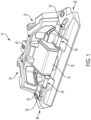
Fig. 1 illustrates a perspective view of an exemplary embodiment of a construction laser tool according to the invention; -
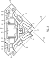
Fig. 2 is a top view of the exemplary embodiment of the construction laser tool; -
Fig. 3 is a top perspective view of the exemplary embodiment of the construction laser tool; -
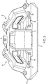
Fig. 4 is a bottom view of the exemplary embodiment of the construction laser tool; -
Fig. 5 is a side view of the exemplary embodiment of the construction laser tool; -
Fig. 6A is a cross-sectional explanatory view of the construction laser tool with pins in a stored position; -
Fig. 6B is a cross-sectional explanatory view of the construction laser tool with pins moving from a stored position, to an actuating position and a securing position; -
Fig. 7 is a close-up, bottom view of a portion the construction laser tool; -
Fig. 8 is a close-up, bottom view of a portion the construction laser tool; -
Fig. 9 is close-up cross-sectional view of a pin and pivot of the construction laser tool; and -
Fig. 10 schematic of a laser projector of the construction laser tool. - An exemplary embodiment of a
construction laser tool 10 is shown inFigs. 1-10 . Theconstruction laser tool 10 of the exemplary embodiment is a tile laser. Thetile laser 10 has abase 50. Thebase 50 has a substantially triangular shape. Abottom surface 51 of thebase 50 is shown inFig. 4 . Thebottom surface 51 similarly has a substantially triangular shape. As shown inFigs. 1-4 , thebase 50 includes afront surface 52 andside surfaces 53 and 54. Thefront surface 52 provides a straight edge, which can be used to draw a straight line. Thefront surface 52 may also be placed against a flat surface, such as a wall, floor or ceiling, and thus help position theconstruction laser tool 10. Theside surfaces 53 and 54 may similarly provide a straight edge for drawing lines or positioning theconstruction laser tool 10. - The
construction laser tool 10 further includescorners Corner 55 includes a 90 degree angle so that it fits into a 90 degree corner, such as that provided by two interior perpendicular walls.Corner 56 provides a 90 degree cut-out. The 90 degree cut-out allows thecorner 56 to be positioned around a 90 degree projection. For example, the outside corner of a building with perpendicular walls. Thecorner 57 provides a 90 degree cut-out and a sloping surface 58. All three of thecorners construction laser tool 10. - The
laser 10 further includes a pair oflaser projectors first laser projector 20, projects a laser beam out of awindow 21. The laser beam projected out ofwindow 21 projects aline 25 onto a surface on which thebottom surface 51 of thelaser 10 is sitting. Theline 25 may be aligned with the window and parallel to theside surface 54. Thesecond laser projector 30, projects a laser beam out of awindow 31. The laser beam projected out ofwindow 31 projects aline 35 onto a surface on which thebottom surface 51 of thelaser 10 is sitting. Theline 35 may be aligned with the window and parallel to the side surface 53.Lines -
Fig. 10 illustrateslaser projector 20 diagrammatically.Laser projector 30 has the same structure aslaser projector 20. As shown inFig. 10 , there is alaser generator 110. Thelaser generator 110 may be a laser diode. Thelaser generator 110 produces a laser beam which passes through a collimator lens 111. The beam then passes through aprism 112 that fans out the beam so that it producesline 25, shown inFig. 2 . These parts, and thewindow 21, may be held in place by acylindrical tube 115. Thelaser generator 110 is powered by the one or more batteries stored in thebattery compartment 70, described below. - As shown in
Figs. 1-4 , there is apower button 60 for actuating thelaser projectors power button 60 may be configured to turn on thelaser projectors first laser projector 20. Actuating the power button 60 a second time may actuate thesecond laser projector 30 and turn off thefirst laser projector 20. Actuating the power button 60 a third time may turn on both thefirst laser projector 20 and thethird laser projector 30 at the same time. Finally, actuating the power button 60 a fourth time may turn both of thelaser projectors power button 60 may simply turn both of thelaser projectors laser projectors laser projectors laser generator 110 mentioned above. - The
tile laser 10 also includes abattery compartment 70. The battery compartment houses one or more batteries for powering thelaser projectors - The
tile laser 10 also includes a pair ofpins 80. Thepins 80 are used to secure thetile laser 10 to a surface. Operation of the pins is best shown inFigs. 6A and 6B . Thetile laser 10 is shown schematically inFigs. 6A and 6B . As shown inFigs. 6A and 6B , thebase 50 of thetile laser 10 is placed on asurface 110. Thesurface 110 may be a sheet rock, concrete board, drywall or other work surface. A user of thetile laser 10 may wish that thetile laser 10 be secured in place, so that it does not move and thelines -
Fig. 6A shows thepins 80 in a stored position.Fig. 6B illustrates one pin 80 (left side ofFig. 6B ) in various states transitioning from a stored to vertical position and asecond pin 80 in shadow from the vertical position to a secured position. When thepins 80 are in the vertical position, they are in an actuation position where they can be actuated to project into thesurface 110 by being pressed towards thesurface 110. In the illustrated embodiment, there is no biasing member, such as a spring. In other embodiments, there may be a biasing member, such as a spring, which biases thepin 80 towards the vertical/actuation position or towards the secured position. There may also be a biasing member which biases thepins 80 either towards the stored position or towards the actuation/vertical position. There may also be detents to secure thepins 80 in the stored position and additional detents to secure thepins 80 in the actuation/vertical position. - As shown in
Figs. 6A and 6B , thepins 80 have a handlingportion 81, andmiddle portion 82 and aprojection portion 83. Thepins 80 rotate around apivot 90. As shown inFig. 6A , thepins 80 can be in a stored position. When in the stored position, thepins 80 are substantially parallel to thesurface 110. Thepins 80 are shown in the stored position inFigs. 1-3 . - On the left side of
Fig. 6B , apin 80 is shown in various different positions from the stored position to a vertical position. In the vertical position, the pin is in position to be pushed into thesurface 110, but does not penetrate the surface. On the right side ofFig. 6B , the pin is shown in an inserted position, in which thepin 80 is pushed into thesurface 110. Specifically, theprojection portion 83 of thepin 80 is pushed into thesurface 110. -
Figs. 7-9 illustrate apin 80 in more detail. Both of thepins 80 in thetile laser 10 are the same.Figs. 7 and 8 are bottom view of thetile laser 10.Fig. 7 is a close-up view of thepin 80 andpivot 90 held in bypivot retainer 95.Fig. 8 is a close-up view of thepin 80 andpivot 90 with theretainer 95 removed.Fig. 9 is a bottom cross-sectional close-up view of the pin. - The
pivot 90 is best seen inFig. 8 . As shown inFig. 8 , thepivot 90 has acentral portion 93 and twoprojections pin 80, specifically themiddle portion 82 of thepin 80, is slidably received. The twoprojections tile laser base 50. Theprojections pin 80 can rotate. As shown inFig. 7 , thepivot retainer 95 is secures thepivot 90 to thetile laser base 50. Thepivot retainer 95 is fastened to thebase 50 by a pair offasteners 96. -
Fig. 9 shows a cross-sectional view of thepin 80 andpivot 90. As shown inFig. 9 , themiddle portion 82 of thepin 80 is received in thecentral portion 93 of thepivot 90. Thepin 80 is shown in the stored position inFig. 9 . As will be appreciated, sliding movement of thepin 80 is restrained at one end by an O-ring 97 and at the other end by a shoulder 84 of the handlingportion 81. That is, when in the vertical position, thepin 80 can be retracted upward, away from thesurface 110, until the O-ring 97 contacts the pivot 90 (specifically thecentral portion 93 of the pivot). Thepin 80 is restrained when being pushed from the upward vertical position to an inserted position by contact of the shoulder 84 and the pivot 90 (again, thecentral portion 93 of the pivot). Thus, the shoulder 84 and the O-ring 97 limit the translation of thepin 80 in thepivot 90. This keeps thepin 80 from being pushed too far into thesurface 110 or retracted too far. Additionally, it secures thepin 80 in thepivot 90, and thus, thetile laser 10. As shown in the various Figs., thepins 80 are additionally restrained by other portions of thetile laser 10 when in the secured position. For example, as shown inFigs. 7 and 8 , thepin 80 can not be extended significantly when in the stored position without hitting a housing portion. - As shown in, for example,
Figs. 6-9 , theprojection portion 83 of thepins 80 is tapered to a point. This allows it to penetrate into thesurface 110. Theprojection portion 83 may be made of metal in order to facilitate insertion into thesurface 110. Theprojection portion 83 is also made thinner than themiddle portion 82 and handlingportion 81 of thepin 80, so as to both facilitate insertion into thesurface 110 and provide minimum visual or structural impact on thesurface 110 when it is inserted into thesurface 110. In other embodiments, theprojection 83 may also be made of other hard materials that can penetrate a surface, for example a hard plastic. - The
pins 80 are rotatable approximately 90 degrees in the exemplary embodiment. In various embodiments, the pins may be rotatable at least 45 degrees or at least 85 degrees. - While shown and described with respect to a tile laser, the
pins 80 may be used on other types of construction laser tools to secure the construction laser tools to a surface or in a particular orientation. For example, thepins 80 may be used to secure a cross-line laser level or rotary laser level to a surface.
Claims (10)
- A construction laser tool (10), comprising:a base (50), the base (50) including a bottom surface (51) configured to be disposed on a work surface (110);a laser projector (20, 30) secured to the base (50), the laser projector (20, 30) comprising a laser generator and configured to project a laser beam onto a work surface (110) when the bottom surface (51) of the base (50) is disposed on the work surface; anda pair of pins (80) for securing the construction laser tool (10) to said work surface, wherein each pin (80) is secured to the base (50) and is pivotable relative to the base (50) about an axis;wherein each pin (80) is pivotable between a stored position and an actuatable position, and when a pin (80) is in an actuatable position it is translatable relative to the base (50) from a position in which it does not extend into said work surface to a position in which it extends into said work surface to secure the construction laser tool (10) to the work surface;characterized in that, when in the stored position, the pins (80) are substantially parallel to said work surface when the bottom surface (51) of the base (50) is disposed on the work surface.
- The construction laser tool (10) of Claim 1, wherein each pin (80) is pivotable between a stored position and a plurality of actuatable positions.
- The construction laser tool (10) of Claim 1 or Claim 2, wherein each pin (80) includes a projection portion (83) which extends into said work surface when the pin (80) secures the construction laser tool (10) to the work surface.
- The construction laser tool (10) of any preceding claim, further comprising a battery compartment (70) configured to receive a battery.
- The construction laser tool (10) of any preceding claim, wherein each pin (80) is pivotable through a range of at least 45 degrees.
- The construction laser tool (10) of any preceding claim, wherein each pin (80) is pivotable through a range of at least 85 degrees.
- The construction laser tool (10) of any preceding claim, further comprising a pair of pivots (90) mounted on the base (50), each attached to a respective pin (80), and each pivot (90) securing its pin (80) to the base (50) and allowing the pin (80) to pivot relative to the base (50).
- The construction laser tool (10) of Claim 7, wherein each pivot (90) includes an opening, and a portion of the pin (80) is slidably disposed in the opening to allow the pin (80) to translate relative to the base (50).
- The construction laser tool (10) of Claim 8, wherein the opening is substantially cylindrical.
- The construction laser tool (10) of any preceding claim, wherein the bottom surface (51) of the base (50) is substantially flat.
Applications Claiming Priority (2)
| Application Number | Priority Date | Filing Date | Title |
|---|---|---|---|
| US201862640655P | 2018-03-09 | 2018-03-09 | |
| US16/185,845 US11175136B2 (en) | 2018-03-09 | 2018-11-09 | Laser level |
Publications (2)
| Publication Number | Publication Date |
|---|---|
| EP3536465A1 EP3536465A1 (en) | 2019-09-11 |
| EP3536465B1 true EP3536465B1 (en) | 2023-02-15 |
Family
ID=65685163
Family Applications (1)
| Application Number | Title | Priority Date | Filing Date |
|---|---|---|---|
| EP19160354.7A Active EP3536465B1 (en) | 2018-03-09 | 2019-03-01 | Construction laser tool |
Country Status (2)
| Country | Link |
|---|---|
| US (1) | US11175136B2 (en) |
| EP (1) | EP3536465B1 (en) |
Families Citing this family (1)
| Publication number | Priority date | Publication date | Assignee | Title |
|---|---|---|---|---|
| US11175136B2 (en) * | 2018-03-09 | 2021-11-16 | Stanley Balck & Decker Inc. | Laser level |
Family Cites Families (51)
| Publication number | Priority date | Publication date | Assignee | Title |
|---|---|---|---|---|
| US1153760A (en) | 1915-02-10 | 1915-09-14 | Frank Butler | Spirit-level. |
| US3897637A (en) | 1974-03-18 | 1975-08-05 | Robert Genho | Laser level and square |
| US4425065A (en) | 1978-08-24 | 1984-01-10 | Theodore Sweeney & Company | Adhesively securable fastener |
| US4208802A (en) | 1979-01-29 | 1980-06-24 | Berndt Stephen R | Level indicating device for wall-mounted pictures |
| US4228982A (en) | 1979-02-12 | 1980-10-21 | Sellera Jose M | Hanging device for pictures |
| US5561911A (en) | 1995-01-19 | 1996-10-08 | Martin; Jeffrey J. | Level tool with laser light alignment capabilities |
| US5531031A (en) | 1995-01-20 | 1996-07-02 | Green; Kevin D. | Laser level and square |
| US5713135A (en) | 1995-10-31 | 1998-02-03 | Acopulos; Brad M. | Multi-purpose carpentry measuring device |
| US6351890B1 (en) | 1996-09-10 | 2002-03-05 | Nigel Emlyn Williams | Laser light referencing tool |
| US5894675A (en) | 1997-02-14 | 1999-04-20 | Cericola; Joseph | Combination tool |
| US6182938B1 (en) | 1997-08-19 | 2001-02-06 | Guy B. Wright | Push button apparatus for wall hangings and calendars |
| US6230416B1 (en) | 1997-12-18 | 2001-05-15 | Anthony J. Trigilio | Laser square |
| US7380759B1 (en) | 1998-11-16 | 2008-06-03 | Garmin Corporation | Multi-position articulating mounting apparatus for an electronic device |
| US20010049879A1 (en) | 2000-01-05 | 2001-12-13 | Moore Robert W. | Laser level and square |
| WO2001064481A2 (en) | 2000-03-02 | 2001-09-07 | Donnelly Corporation | Video mirror systems incorporating an accessory module |
| US6643019B1 (en) | 2000-04-13 | 2003-11-04 | Jack D. Jeanneret | Laser alignment device |
| US6449855B1 (en) | 2000-05-30 | 2002-09-17 | Daniel P. Louis | Laser aligning and measuring device |
| US6532675B2 (en) | 2001-04-18 | 2003-03-18 | Guy Letourneau | Device for measuring the angle of orientation with reference to a known frame of reference between a first object having a first axis and a second remote destination |
| EP1393016A4 (en) | 2001-05-15 | 2007-03-21 | American Tool Comp Inc | Laser line generating device |
| US7278218B2 (en) * | 2003-06-18 | 2007-10-09 | Irwin Industrial Tool Company | Laser line generating device with swivel base |
| USD460924S1 (en) | 2001-08-10 | 2002-07-30 | James N. Hitchcock | Multi-function layout square with laser, level and compass |
| DE50111319D1 (en) * | 2001-09-28 | 2006-12-07 | Hilti Ag | Self-leveling construction laser |
| US6625895B2 (en) | 2001-12-04 | 2003-09-30 | Toolz, Ltd. | Servo-controlled automatic level and plumb tool |
| US6839974B1 (en) | 2002-07-29 | 2005-01-11 | James N. Hitchcock | Multi-function layout square with laser |
| CN2588326Y (en) * | 2002-12-27 | 2003-11-26 | 南京泉峰国际贸易有限公司 | Laser line marking device |
| US6880256B2 (en) * | 2003-02-21 | 2005-04-19 | Paccar Inc | Alignment device |
| US6864799B2 (en) | 2003-04-23 | 2005-03-08 | Gregory S. Popps | Emergency lighting device for firefighters |
| US6931740B2 (en) | 2003-04-30 | 2005-08-23 | Black & Decker Inc. | Line generating device |
| US7013570B2 (en) | 2003-06-18 | 2006-03-21 | Irwin-Industrial Tool Company | Stud finder |
| US7269907B2 (en) * | 2003-07-01 | 2007-09-18 | Irwin Industrial Tool Company | Laser line generating device with swivel base |
| US20050022399A1 (en) | 2003-08-01 | 2005-02-03 | Wheeler Thomas J. | Laser level |
| US7237341B2 (en) | 2003-10-10 | 2007-07-03 | The Stanley Works | Studfinder and laser line layout tool |
| US20050198845A1 (en) * | 2004-02-19 | 2005-09-15 | Glenn Robinson | Multiple laser laser level |
| JP2005265425A (en) | 2004-03-16 | 2005-09-29 | Gonoi Tile Kogyo:Kk | Ruler using laser beam |
| US6941665B1 (en) * | 2004-03-17 | 2005-09-13 | Awi Acquisition Company, Inc. | Pivotable laser level |
| US7213342B2 (en) | 2004-03-22 | 2007-05-08 | Ideavillage Products Corp. | Wall mountable laser level |
| CN2718518Y (en) | 2004-06-18 | 2005-08-17 | 南京德朔实业有限公司 | Laser striping machine |
| US7487596B2 (en) | 2004-06-25 | 2009-02-10 | Irwin Industrial Tool Company | Laser line projected on an edge of a surface |
| US7181854B2 (en) * | 2004-08-17 | 2007-02-27 | Eastway Fair Company Limited | Laser leveling device having a suction mounting arrangement |
| IL169436A0 (en) * | 2005-06-28 | 2007-07-04 | Kapro Ind Ltd | Handheld diy tool |
| CN2797731Y (en) | 2004-11-30 | 2006-07-19 | 常州市莱赛激光工程有限公司 | Means suitable for connecting plane |
| US7497019B2 (en) | 2005-08-04 | 2009-03-03 | Irwin Industrial Tool Company | Laser reference device |
| US7845083B1 (en) | 2007-07-13 | 2010-12-07 | Edgardo Cora Rosa | Stabilized T-square |
| US7748126B2 (en) | 2007-10-17 | 2010-07-06 | Jianhong Lu | Laser straight liner |
| US20100122466A1 (en) | 2008-11-19 | 2010-05-20 | The Wiremold Company | Alignment apparatus |
| US7886450B1 (en) * | 2009-01-04 | 2011-02-15 | Joseph Fiano | Elevated laser beam positioning device |
| US8519861B2 (en) | 2010-09-20 | 2013-08-27 | Black & Decker Inc. | Tool system with mount configured to be removably coupled to a surface |
| US8966776B2 (en) | 2011-02-25 | 2015-03-03 | KellyCraft Innovations, LLC | Laser square |
| US10165875B2 (en) | 2016-04-26 | 2019-01-01 | Magnus Inventions Llc | Picture hanging marking tool |
| US10119817B2 (en) * | 2016-04-28 | 2018-11-06 | Stanley Black & Decker Inc. | Laser level |
| US11175136B2 (en) * | 2018-03-09 | 2021-11-16 | Stanley Balck & Decker Inc. | Laser level |
-
2018
- 2018-11-09 US US16/185,845 patent/US11175136B2/en active Active
-
2019
- 2019-03-01 EP EP19160354.7A patent/EP3536465B1/en active Active
Also Published As
| Publication number | Publication date |
|---|---|
| EP3536465A1 (en) | 2019-09-11 |
| US11175136B2 (en) | 2021-11-16 |
| US20190277633A1 (en) | 2019-09-12 |
Similar Documents
| Publication | Publication Date | Title |
|---|---|---|
| US7181854B2 (en) | Laser leveling device having a suction mounting arrangement | |
| EP1962053A2 (en) | Light line generating assembly | |
| US6301997B1 (en) | Positioning device for power-driven fastener | |
| US3845554A (en) | Knife blade and handle | |
| US20040205972A2 (en) | Laser level with adjustable laser projection line | |
| AU2005203170A1 (en) | Laser line generating device with swivel base | |
| AU2009233670A1 (en) | Dual Front Utility Knife with Interlock | |
| US8434235B2 (en) | Utility knife blade release mechanism | |
| EP3536465B1 (en) | Construction laser tool | |
| US11906304B2 (en) | Magnetic laser stud finder | |
| CA2983825C (en) | Tape measure device and attachment for measuring and cutting drywall | |
| US10321596B2 (en) | Job-site electric apparatus and method for reducing invasion of foreign matter into job-site electric apparatus | |
| US11759970B2 (en) | Power tool attachment saw | |
| US20250236436A1 (en) | Reversible stacking mating interface | |
| US10309780B1 (en) | Laser measuring device | |
| EP1382423B1 (en) | Paper abutted ruler | |
| US12560276B2 (en) | Target support tool | |
| JP2003311660A (en) | Tool holder | |
| JP3928967B2 (en) | Electronic device having a storage portion and a waterproof detachable lid covering the opening | |
| JP2928501B2 (en) | Board cutter and board cutting method | |
| US20180120076A1 (en) | Tape measure device and attachment for measuring and cutting drywall | |
| JP2023048302A (en) | target support | |
| US20080052926A1 (en) | Gravity dial level indicator for line generator | |
| CA2504467A1 (en) | Drywall measuring tape | |
| JPH11319336A (en) | Retractable knife |
Legal Events
| Date | Code | Title | Description |
|---|---|---|---|
| PUAI | Public reference made under article 153(3) epc to a published international application that has entered the european phase |
Free format text: ORIGINAL CODE: 0009012 |
|
| STAA | Information on the status of an ep patent application or granted ep patent |
Free format text: STATUS: THE APPLICATION HAS BEEN PUBLISHED |
|
| AK | Designated contracting states |
Kind code of ref document: A1 Designated state(s): AL AT BE BG CH CY CZ DE DK EE ES FI FR GB GR HR HU IE IS IT LI LT LU LV MC MK MT NL NO PL PT RO RS SE SI SK SM TR |
|
| AX | Request for extension of the european patent |
Extension state: BA ME |
|
| STAA | Information on the status of an ep patent application or granted ep patent |
Free format text: STATUS: REQUEST FOR EXAMINATION WAS MADE |
|
| 17P | Request for examination filed |
Effective date: 20200310 |
|
| RBV | Designated contracting states (corrected) |
Designated state(s): AL AT BE BG CH CY CZ DE DK EE ES FI FR GB GR HR HU IE IS IT LI LT LU LV MC MK MT NL NO PL PT RO RS SE SI SK SM TR |
|
| GRAP | Despatch of communication of intention to grant a patent |
Free format text: ORIGINAL CODE: EPIDOSNIGR1 |
|
| STAA | Information on the status of an ep patent application or granted ep patent |
Free format text: STATUS: GRANT OF PATENT IS INTENDED |
|
| INTG | Intention to grant announced |
Effective date: 20221111 |
|
| GRAS | Grant fee paid |
Free format text: ORIGINAL CODE: EPIDOSNIGR3 |
|
| GRAA | (expected) grant |
Free format text: ORIGINAL CODE: 0009210 |
|
| STAA | Information on the status of an ep patent application or granted ep patent |
Free format text: STATUS: THE PATENT HAS BEEN GRANTED |
|
| AK | Designated contracting states |
Kind code of ref document: B1 Designated state(s): AL AT BE BG CH CY CZ DE DK EE ES FI FR GB GR HR HU IE IS IT LI LT LU LV MC MK MT NL NO PL PT RO RS SE SI SK SM TR |
|
| REG | Reference to a national code |
Ref country code: CH Ref legal event code: EP Ref country code: GB Ref legal event code: FG4D |
|
| REG | Reference to a national code |
Ref country code: DE Ref legal event code: R096 Ref document number: 602019025195 Country of ref document: DE |
|
| REG | Reference to a national code |
Ref country code: AT Ref legal event code: REF Ref document number: 1547999 Country of ref document: AT Kind code of ref document: T Effective date: 20230315 Ref country code: IE Ref legal event code: FG4D |
|
| REG | Reference to a national code |
Ref country code: LT Ref legal event code: MG9D |
|
| REG | Reference to a national code |
Ref country code: NL Ref legal event code: MP Effective date: 20230215 |
|
| REG | Reference to a national code |
Ref country code: AT Ref legal event code: MK05 Ref document number: 1547999 Country of ref document: AT Kind code of ref document: T Effective date: 20230215 |
|
| PG25 | Lapsed in a contracting state [announced via postgrant information from national office to epo] |
Ref country code: RS Free format text: LAPSE BECAUSE OF FAILURE TO SUBMIT A TRANSLATION OF THE DESCRIPTION OR TO PAY THE FEE WITHIN THE PRESCRIBED TIME-LIMIT Effective date: 20230215 Ref country code: PT Free format text: LAPSE BECAUSE OF FAILURE TO SUBMIT A TRANSLATION OF THE DESCRIPTION OR TO PAY THE FEE WITHIN THE PRESCRIBED TIME-LIMIT Effective date: 20230615 Ref country code: NO Free format text: LAPSE BECAUSE OF FAILURE TO SUBMIT A TRANSLATION OF THE DESCRIPTION OR TO PAY THE FEE WITHIN THE PRESCRIBED TIME-LIMIT Effective date: 20230515 Ref country code: NL Free format text: LAPSE BECAUSE OF FAILURE TO SUBMIT A TRANSLATION OF THE DESCRIPTION OR TO PAY THE FEE WITHIN THE PRESCRIBED TIME-LIMIT Effective date: 20230215 Ref country code: LV Free format text: LAPSE BECAUSE OF FAILURE TO SUBMIT A TRANSLATION OF THE DESCRIPTION OR TO PAY THE FEE WITHIN THE PRESCRIBED TIME-LIMIT Effective date: 20230215 Ref country code: LT Free format text: LAPSE BECAUSE OF FAILURE TO SUBMIT A TRANSLATION OF THE DESCRIPTION OR TO PAY THE FEE WITHIN THE PRESCRIBED TIME-LIMIT Effective date: 20230215 Ref country code: HR Free format text: LAPSE BECAUSE OF FAILURE TO SUBMIT A TRANSLATION OF THE DESCRIPTION OR TO PAY THE FEE WITHIN THE PRESCRIBED TIME-LIMIT Effective date: 20230215 Ref country code: ES Free format text: LAPSE BECAUSE OF FAILURE TO SUBMIT A TRANSLATION OF THE DESCRIPTION OR TO PAY THE FEE WITHIN THE PRESCRIBED TIME-LIMIT Effective date: 20230215 Ref country code: AT Free format text: LAPSE BECAUSE OF FAILURE TO SUBMIT A TRANSLATION OF THE DESCRIPTION OR TO PAY THE FEE WITHIN THE PRESCRIBED TIME-LIMIT Effective date: 20230215 |
|
| PG25 | Lapsed in a contracting state [announced via postgrant information from national office to epo] |
Ref country code: SE Free format text: LAPSE BECAUSE OF FAILURE TO SUBMIT A TRANSLATION OF THE DESCRIPTION OR TO PAY THE FEE WITHIN THE PRESCRIBED TIME-LIMIT Effective date: 20230215 Ref country code: PL Free format text: LAPSE BECAUSE OF FAILURE TO SUBMIT A TRANSLATION OF THE DESCRIPTION OR TO PAY THE FEE WITHIN THE PRESCRIBED TIME-LIMIT Effective date: 20230215 Ref country code: IS Free format text: LAPSE BECAUSE OF FAILURE TO SUBMIT A TRANSLATION OF THE DESCRIPTION OR TO PAY THE FEE WITHIN THE PRESCRIBED TIME-LIMIT Effective date: 20230615 Ref country code: GR Free format text: LAPSE BECAUSE OF FAILURE TO SUBMIT A TRANSLATION OF THE DESCRIPTION OR TO PAY THE FEE WITHIN THE PRESCRIBED TIME-LIMIT Effective date: 20230516 Ref country code: FI Free format text: LAPSE BECAUSE OF FAILURE TO SUBMIT A TRANSLATION OF THE DESCRIPTION OR TO PAY THE FEE WITHIN THE PRESCRIBED TIME-LIMIT Effective date: 20230215 |
|
| P01 | Opt-out of the competence of the unified patent court (upc) registered |
Effective date: 20230912 |
|
| PG25 | Lapsed in a contracting state [announced via postgrant information from national office to epo] |
Ref country code: SM Free format text: LAPSE BECAUSE OF FAILURE TO SUBMIT A TRANSLATION OF THE DESCRIPTION OR TO PAY THE FEE WITHIN THE PRESCRIBED TIME-LIMIT Effective date: 20230215 Ref country code: RO Free format text: LAPSE BECAUSE OF FAILURE TO SUBMIT A TRANSLATION OF THE DESCRIPTION OR TO PAY THE FEE WITHIN THE PRESCRIBED TIME-LIMIT Effective date: 20230215 Ref country code: EE Free format text: LAPSE BECAUSE OF FAILURE TO SUBMIT A TRANSLATION OF THE DESCRIPTION OR TO PAY THE FEE WITHIN THE PRESCRIBED TIME-LIMIT Effective date: 20230215 Ref country code: DK Free format text: LAPSE BECAUSE OF FAILURE TO SUBMIT A TRANSLATION OF THE DESCRIPTION OR TO PAY THE FEE WITHIN THE PRESCRIBED TIME-LIMIT Effective date: 20230215 Ref country code: CZ Free format text: LAPSE BECAUSE OF FAILURE TO SUBMIT A TRANSLATION OF THE DESCRIPTION OR TO PAY THE FEE WITHIN THE PRESCRIBED TIME-LIMIT Effective date: 20230215 |
|
| REG | Reference to a national code |
Ref country code: CH Ref legal event code: PL |
|
| REG | Reference to a national code |
Ref country code: DE Ref legal event code: R097 Ref document number: 602019025195 Country of ref document: DE |
|
| PG25 | Lapsed in a contracting state [announced via postgrant information from national office to epo] |
Ref country code: SK Free format text: LAPSE BECAUSE OF FAILURE TO SUBMIT A TRANSLATION OF THE DESCRIPTION OR TO PAY THE FEE WITHIN THE PRESCRIBED TIME-LIMIT Effective date: 20230215 |
|
| REG | Reference to a national code |
Ref country code: BE Ref legal event code: MM Effective date: 20230331 |
|
| PLBE | No opposition filed within time limit |
Free format text: ORIGINAL CODE: 0009261 |
|
| STAA | Information on the status of an ep patent application or granted ep patent |
Free format text: STATUS: NO OPPOSITION FILED WITHIN TIME LIMIT |
|
| PG25 | Lapsed in a contracting state [announced via postgrant information from national office to epo] |
Ref country code: LU Free format text: LAPSE BECAUSE OF NON-PAYMENT OF DUE FEES Effective date: 20230301 |
|
| PG25 | Lapsed in a contracting state [announced via postgrant information from national office to epo] |
Ref country code: MC Free format text: LAPSE BECAUSE OF FAILURE TO SUBMIT A TRANSLATION OF THE DESCRIPTION OR TO PAY THE FEE WITHIN THE PRESCRIBED TIME-LIMIT Effective date: 20230215 |
|
| REG | Reference to a national code |
Ref country code: IE Ref legal event code: MM4A |
|
| 26N | No opposition filed |
Effective date: 20231116 |
|
| PG25 | Lapsed in a contracting state [announced via postgrant information from national office to epo] |
Ref country code: SI Free format text: LAPSE BECAUSE OF FAILURE TO SUBMIT A TRANSLATION OF THE DESCRIPTION OR TO PAY THE FEE WITHIN THE PRESCRIBED TIME-LIMIT Effective date: 20230215 Ref country code: MC Free format text: LAPSE BECAUSE OF FAILURE TO SUBMIT A TRANSLATION OF THE DESCRIPTION OR TO PAY THE FEE WITHIN THE PRESCRIBED TIME-LIMIT Effective date: 20230215 Ref country code: LI Free format text: LAPSE BECAUSE OF NON-PAYMENT OF DUE FEES Effective date: 20230331 Ref country code: IE Free format text: LAPSE BECAUSE OF NON-PAYMENT OF DUE FEES Effective date: 20230301 Ref country code: FR Free format text: LAPSE BECAUSE OF NON-PAYMENT OF DUE FEES Effective date: 20230415 Ref country code: CH Free format text: LAPSE BECAUSE OF NON-PAYMENT OF DUE FEES Effective date: 20230331 |
|
| PG25 | Lapsed in a contracting state [announced via postgrant information from national office to epo] |
Ref country code: BE Free format text: LAPSE BECAUSE OF NON-PAYMENT OF DUE FEES Effective date: 20230331 |
|
| PG25 | Lapsed in a contracting state [announced via postgrant information from national office to epo] |
Ref country code: IT Free format text: LAPSE BECAUSE OF FAILURE TO SUBMIT A TRANSLATION OF THE DESCRIPTION OR TO PAY THE FEE WITHIN THE PRESCRIBED TIME-LIMIT Effective date: 20230215 |
|
| PG25 | Lapsed in a contracting state [announced via postgrant information from national office to epo] |
Ref country code: BG Free format text: LAPSE BECAUSE OF FAILURE TO SUBMIT A TRANSLATION OF THE DESCRIPTION OR TO PAY THE FEE WITHIN THE PRESCRIBED TIME-LIMIT Effective date: 20230215 |
|
| PG25 | Lapsed in a contracting state [announced via postgrant information from national office to epo] |
Ref country code: BG Free format text: LAPSE BECAUSE OF FAILURE TO SUBMIT A TRANSLATION OF THE DESCRIPTION OR TO PAY THE FEE WITHIN THE PRESCRIBED TIME-LIMIT Effective date: 20230215 |
|
| PG25 | Lapsed in a contracting state [announced via postgrant information from national office to epo] |
Ref country code: CY Free format text: LAPSE BECAUSE OF FAILURE TO SUBMIT A TRANSLATION OF THE DESCRIPTION OR TO PAY THE FEE WITHIN THE PRESCRIBED TIME-LIMIT; INVALID AB INITIO Effective date: 20190301 |
|
| PG25 | Lapsed in a contracting state [announced via postgrant information from national office to epo] |
Ref country code: HU Free format text: LAPSE BECAUSE OF FAILURE TO SUBMIT A TRANSLATION OF THE DESCRIPTION OR TO PAY THE FEE WITHIN THE PRESCRIBED TIME-LIMIT; INVALID AB INITIO Effective date: 20190301 |
|
| PG25 | Lapsed in a contracting state [announced via postgrant information from national office to epo] |
Ref country code: TR Free format text: LAPSE BECAUSE OF FAILURE TO SUBMIT A TRANSLATION OF THE DESCRIPTION OR TO PAY THE FEE WITHIN THE PRESCRIBED TIME-LIMIT Effective date: 20230215 |
|
| PGFP | Annual fee paid to national office [announced via postgrant information from national office to epo] |
Ref country code: GB Payment date: 20260324 Year of fee payment: 8 |
|
| PGFP | Annual fee paid to national office [announced via postgrant information from national office to epo] |
Ref country code: DE Payment date: 20260320 Year of fee payment: 8 |