EP3536427A1 - Turning tool and turning method for cnc-machines - Google Patents
Turning tool and turning method for cnc-machines Download PDFInfo
- Publication number
- EP3536427A1 EP3536427A1 EP18160706.0A EP18160706A EP3536427A1 EP 3536427 A1 EP3536427 A1 EP 3536427A1 EP 18160706 A EP18160706 A EP 18160706A EP 3536427 A1 EP3536427 A1 EP 3536427A1
- Authority
- EP
- European Patent Office
- Prior art keywords
- cutting
- tool
- insert
- nose
- rotational axis
- Prior art date
- Legal status (The legal status is an assumption and is not a legal conclusion. Google has not performed a legal analysis and makes no representation as to the accuracy of the status listed.)
- Granted
Links
Images




Classifications
-
- B—PERFORMING OPERATIONS; TRANSPORTING
- B23—MACHINE TOOLS; METAL-WORKING NOT OTHERWISE PROVIDED FOR
- B23B—TURNING; BORING
- B23B27/00—Tools for turning or boring machines; Tools of a similar kind in general; Accessories therefor
- B23B27/14—Cutting tools of which the bits or tips or cutting inserts are of special material
- B23B27/16—Cutting tools of which the bits or tips or cutting inserts are of special material with exchangeable cutting bits or cutting inserts, e.g. able to be clamped
- B23B27/1603—Cutting tools of which the bits or tips or cutting inserts are of special material with exchangeable cutting bits or cutting inserts, e.g. able to be clamped with specially shaped plate-like exchangeable cutting inserts, e.g. chip-breaking groove
- B23B27/1607—Cutting tools of which the bits or tips or cutting inserts are of special material with exchangeable cutting bits or cutting inserts, e.g. able to be clamped with specially shaped plate-like exchangeable cutting inserts, e.g. chip-breaking groove characterised by having chip-breakers
-
- B—PERFORMING OPERATIONS; TRANSPORTING
- B23—MACHINE TOOLS; METAL-WORKING NOT OTHERWISE PROVIDED FOR
- B23B—TURNING; BORING
- B23B27/00—Tools for turning or boring machines; Tools of a similar kind in general; Accessories therefor
- B23B27/14—Cutting tools of which the bits or tips or cutting inserts are of special material
- B23B27/16—Cutting tools of which the bits or tips or cutting inserts are of special material with exchangeable cutting bits or cutting inserts, e.g. able to be clamped
- B23B27/1603—Cutting tools of which the bits or tips or cutting inserts are of special material with exchangeable cutting bits or cutting inserts, e.g. able to be clamped with specially shaped plate-like exchangeable cutting inserts, e.g. chip-breaking groove
- B23B27/1611—Cutting tools of which the bits or tips or cutting inserts are of special material with exchangeable cutting bits or cutting inserts, e.g. able to be clamped with specially shaped plate-like exchangeable cutting inserts, e.g. chip-breaking groove characterised by having a special shape
-
- B—PERFORMING OPERATIONS; TRANSPORTING
- B23—MACHINE TOOLS; METAL-WORKING NOT OTHERWISE PROVIDED FOR
- B23B—TURNING; BORING
- B23B27/00—Tools for turning or boring machines; Tools of a similar kind in general; Accessories therefor
- B23B27/14—Cutting tools of which the bits or tips or cutting inserts are of special material
- B23B27/16—Cutting tools of which the bits or tips or cutting inserts are of special material with exchangeable cutting bits or cutting inserts, e.g. able to be clamped
-
- B—PERFORMING OPERATIONS; TRANSPORTING
- B23—MACHINE TOOLS; METAL-WORKING NOT OTHERWISE PROVIDED FOR
- B23B—TURNING; BORING
- B23B1/00—Methods for turning or working essentially requiring the use of turning-machines; Use of auxiliary equipment in connection with such methods
-
- B—PERFORMING OPERATIONS; TRANSPORTING
- B23—MACHINE TOOLS; METAL-WORKING NOT OTHERWISE PROVIDED FOR
- B23B—TURNING; BORING
- B23B27/00—Tools for turning or boring machines; Tools of a similar kind in general; Accessories therefor
- B23B27/14—Cutting tools of which the bits or tips or cutting inserts are of special material
- B23B27/141—Specially shaped plate-like cutting inserts, i.e. length greater or equal to width, width greater than or equal to thickness
- B23B27/143—Specially shaped plate-like cutting inserts, i.e. length greater or equal to width, width greater than or equal to thickness characterised by having chip-breakers
-
- B—PERFORMING OPERATIONS; TRANSPORTING
- B23—MACHINE TOOLS; METAL-WORKING NOT OTHERWISE PROVIDED FOR
- B23B—TURNING; BORING
- B23B2200/00—Details of cutting inserts
- B23B2200/04—Overall shape
- B23B2200/049—Triangular
-
- B—PERFORMING OPERATIONS; TRANSPORTING
- B23—MACHINE TOOLS; METAL-WORKING NOT OTHERWISE PROVIDED FOR
- B23B—TURNING; BORING
- B23B2200/00—Details of cutting inserts
- B23B2200/16—Supporting or bottom surfaces
- B23B2200/161—Supporting or bottom surfaces with projections
-
- B—PERFORMING OPERATIONS; TRANSPORTING
- B23—MACHINE TOOLS; METAL-WORKING NOT OTHERWISE PROVIDED FOR
- B23B—TURNING; BORING
- B23B2200/00—Details of cutting inserts
- B23B2200/16—Supporting or bottom surfaces
- B23B2200/165—Supporting or bottom surfaces with one or more grooves
-
- B—PERFORMING OPERATIONS; TRANSPORTING
- B23—MACHINE TOOLS; METAL-WORKING NOT OTHERWISE PROVIDED FOR
- B23B—TURNING; BORING
- B23B2205/00—Fixation of cutting inserts in holders
- B23B2205/12—Seats for cutting inserts
-
- B—PERFORMING OPERATIONS; TRANSPORTING
- B23—MACHINE TOOLS; METAL-WORKING NOT OTHERWISE PROVIDED FOR
- B23B—TURNING; BORING
- B23B2210/00—Details of turning tools
- B23B2210/06—Chip breakers
-
- B—PERFORMING OPERATIONS; TRANSPORTING
- B23—MACHINE TOOLS; METAL-WORKING NOT OTHERWISE PROVIDED FOR
- B23B—TURNING; BORING
- B23B29/00—Holders for non-rotary cutting tools; Boring bars or boring heads; Accessories for tool holders
- B23B29/04—Tool holders for a single cutting tool
- B23B29/046—Tool holders for a single cutting tool with an intermediary toolholder
Definitions
- the present invention belongs to the technical field of metal cutting. More specifically the present invention belongs to the field of cutting tools for turning of a metal work piece, by use of computer or computerized numerical control, i.e. CNC, machines.
- the present invention relates to a cutting tool for turning, comprising a coupling portion, an intermediate portion and a cutting portion, the intermediate portion extending between the coupling portion and the cutting portion, the intermediate portion extending along a longitudinal center axis thereof, the cutting portion comprising a first and a second nose portion, the first and second nose portions being permanently connected, the first nose portion comprising a first cutting edge, a second cutting edge, and a convex nose cutting edge connecting the first and second cutting edges, and the first and second cutting edges forming a nose angle less than 90°.
- EP1158378B1 claims to provide a machine tool capable of machining in a plurality of machining modes with a single tool, wherein the loss of machining time due to tool change can be decreased and the number of tools to be prepared can be decreased.
- a conventional tool comprising a cutting insert, comprising two opposite nose portions of around 55° nose angle, mounted in a tool body, such that one nose portion is a free end and thereby in an active or usable position.
- a slot machining (tool positions 25F, 25G in Fig. 7 ) is shown.
- a so called B-axis can be set to a number of angles.
- the inventor has found that there is a need for an improved turning tool which can used in an improved method. For example, when machining a slot using the above described method and tool, the degree of B-angle adjustment possible is limited because of geometrical factors, especially the depth and width of the slot. For a relatively deep and narrow slot, there is an increased risk of interference between the tool body and the work piece. A further need for improvement which the inventor has found relates to the risk of vibrations, especially if cutting tools having a great overhang is used, such as in deep slot turning. A still further need for improvement relates to reducing the down-time for a CNC-machine.
- An object of the present invention is to provide an improved turning tool.
- the cutting tool according to claim 1. is characterized in that a longitudinal center axis of the coupling portion defines a tool rotational axis, the intermediate portion extending along a longitudinal center axis thereof, the longitudinal center axis being parallel to or co-linear with the tool rotational axis, the cutting portion comprising a top surface, the top surface is facing away from the coupling portion, the first and the second nose portions each form free ends of the cutting tool, in that in a top view, the first and second nose portions form an angle of more than 90° relative to each other measured around the longitudinal center axis of the intermediate portion, and in that in a top view, a first extension line co-linear with the first cutting edge and a second extension line co-linear with the second cutting edge extends on opposite sides relative to the longitudinal center axis of the intermediate portion.
- change to a new nose portion can be made by an automatic or manual step which involves removing, i.e. un-clamping, the used cutting tool from the machine interface.
- the present cutting tool provides a less time-consuming option.
- the cutting tool is suitable for turning metal work pieces.
- the cutting tool is a turning tool which can be used for cutting a rotating metal work piece.
- the cutting tool comprising a coupling portion is suitable to be connected directly, or by one or more tool devices, to a rotatable machine interface, e.g. a spindle, of a machine tool which can be used for turning, such as e.g. a turning lathe, a multi task machine, a turn-mill machine, or a sliding head machine.
- the machine tool is preferably a CNC-machine, i.e. computer or computerized numerical control, machine.
- the coupling portion preferably comprise a conical or substantially conical portion and a ring-shaped portion, such as preferably in the form of a polygonal hollow taper interface with a flange contact surface, such in accordance to ISO 26623-1:2014, or a hollow taper with a flange contact surface such as in accordance to DIN 69893, ISO 12164-1 or ISO 12164-1F.
- the conical portion and the ring-shaped portion are preferably concentric. In relation to the conical portion, the ring-shaped portion preferably extends a greater radial distance in relation to the tool rotational axis.
- a longitudinal center axis of the coupling portion defines a tool rotational axis.
- the coupling portion is mounted in the machine interface, e.g. the machine spindle, the cutting tool is rotatable around the tool rotational axis.
- the cutting tool is arranged to be rotatable around the tool rotational axis.
- the tool rotational axis is a longitudinal center axis of the coupling portion.
- the cutting tool is arranged to be rotatable around a tool rotational axis thereof.
- the coupling portion is preferably arranged symmetrically or substantially symmetrically around the tool rotational axis.
- the coupling portion is preferably permanently connected to the intermediate portion, thereby forming a tool body.
- the coupling portion and the intermediate portion are preferably made from steel.
- the intermediate portion extends between and connects the coupling portion and the cutting portion.
- the intermediate portion extends along a longitudinal center axis thereof.
- the intermediate portion is preferably arranged symmetrically or substantially symmetrically around the longitudinal center axis thereof. In cross sections perpendicular to the rotational axis, the intermediate portion preferably is greater in size, i.e. has a larger area at a rear end thereof, i.e.
- the longitudinal center axis being parallel to or co-linear, i.e. co-axial, with the tool rotational axis.
- the longitudinal center axis being parallel to the tool rotational axis means that the longitudinal center axis is spaced apart from the tool rotational axis.
- the cutting tool comprises a cutting portion.
- the cutting portion defines a front end of the cutting tool.
- the coupling portion defines a rear end of the cutting tool.
- the cutting is preferably in the form of a cutting insert made from a hard and wear resistant material such as e.g. cemented carbide, cermet, cubic boron nitride (CBN) or ceramic.
- the cutting insert is preferably detachably mounted in an insert seat formed in a front end of the intermediate portion.
- the cutting portion, the coupling portion and the intermediate portion is a singular body.
- the cutting portion comprising a top surface comprising a rake face. The top surface is facing away from the coupling portion.
- the cutting tool is preferably elongated in the direction of the longitudinal center axis of the intermediate portion, such that a distance from the top surface to the clamping portion is greater than a maximum diameter of the cutting tool measured in a plane perpendicular to the longitudinal center axis of the intermediate portion.
- the cutting portion comprises a first and a second nose portion.
- a nose portion can alternatively be designated as a corner portion.
- the first and second nose portions are permanently connected to each other.
- the first and second nose portions are in the form of nose portions of one cutting insert.
- the first nose portion comprises a first cutting edge, a second cutting edge, and a convex nose cutting edge connecting the first and second cutting edges.
- the nose cutting edge is in top view preferably convexly curved, such as a circular arc having a radius of curvature of 0.15 - 1.3 mm, even more preferably 0.3 - 0.9 mm.
- the nose cutting edge may in top view have a convex shape, which convex shape deviates from a perfect circular arc, such as a shape which comprises two or more circular arcs having different radii of curvature.
- the nose cutting edge may be a so-called wiper nose cutting edge.
- the nose cutting edge is the most distal portion of the cutting portion in relation to the longitudinal center axis of the intermediate portion.
- the top surface preferably comprises chip breaking means, preferably in the form of one or more protrusions, preferably located in the vicinity of i.e. less than 3 mm from the nose cutting edge.
- the first and second cutting edges are each in a top view preferably straight or substantially straight.
- a bisector formed mid-way between the first and second cutting edges intersects the longitudinal center axis of the intermediate portion.
- the second nose portion comprises a convexly curved nose cutting edge, such that the convexly curved nose cutting edges of the first and second nose portion, respectively, being positioned in a common plane perpendicular to the tool rotational axis.
- the first and second cutting edges in a top view forms a nose angle which is less than 90°, preferably 15° - 85°, even more preferably 20° - 40°.
- the first and the second nose portions each form free ends of the cutting tool.
- the first and the second nose portions each form radially outer portions of the cutting portion, where radially outer refers to the longitudinal axis of the intermediate portion.
- the first and the second nose portions comprises radially outer end portions of the front end of the cutting tool.
- the first and the second nose portions are arranged to be alternatively active.
- the first and second nose portions form radially distal portions of the front end of the cutting tool, where said radial distances is in relation to the longitudinal center axis of the intermediate portion.
- the first and second nose portions are preferably located at equal distances from the longitudinal center axis of the intermediate portion. Alternatively, said distances may vary, preferably by less than 30 %, even more preferably by less than 10 %.
- the first and second nose portions may preferably be formed in a corresponding manner.
- the second nose portion may be arranged differently, i.e. having a different shape or chemical composition, compared to the first nose portion, e.g. having a different shape in a top view and/or comprising a nose cutting edge having a curvature which in a top view differs from a curvature of nose cutting edge of the first nose portion.
- the first and second nose portions form an angle of more than 90°, preferably 120° or 180°, relative to each other, measured around the longitudinal center axis of the intermediate portion.
- a first extension line co-linear with the first cutting edge and a second extension line co-linear with the second cutting edge extends on opposite sides relative to the longitudinal center axis of the intermediate portion.
- an extension of a bisector formed between the first and second cutting edges intersect the longitudinal center axis of the intermediate portion.
- the cutting portion is inside a circle having a diameter of 50 mm, more preferably inside a circle having a diameter of 35 mm.
- the cutting tool has a length measured along or parallel to the tool rotational axis which is 80 - 400 mm, more preferably 90 - 250 mm.
- the cutting tool has a maximum diameter, measured perpendicular to the tool rotational axis, which is less than the said length of the cutting tool, preferably 0.2 - 0.8 times said length.
- the length of the coupling portion measured along or parallel to the tool rotational axis is less than the length of the intermediate portion.
- the length of the cutting portion measured along or parallel to the tool rotational axis is less than the length of the intermediate portion, more preferably less than 15 % of the length of the intermediate portion.
- the coupling portion and the intermediate portion jointly form a tool body, wherein the cutting portion being in the form of a first cutting insert, wherein a front end of the tool body is defined by a first insert seat for the first cutting insert, wherein the first cutting insert is detachably clamped in the first insert seat by clamping means, wherein the first cutting insert comprising a bottom surface opposite the top surface, wherein a side surface connects the top and bottom surfaces, wherein a mid-plane extends mid-way between the top and bottom surfaces, and wherein the nose cutting edge is in top view convexly curved having a radius of curvature of 0.15 - 1.3 mm.
- the cutting tool comprises a first cutting insert, preferably made from a hard and wear resistant material suitable for metal cutting, such as preferably cemented carbide.
- the cutting tool comprises a tool body, preferably made from a comparably less wear resistant material such as e.g. steel.
- the tool body comprises the coupling portion and the intermediate portion. The coupling portion and the intermediate portion are permanently connected, thereby forming the tool body in the form of a singular body.
- the tool body extends longitudinally between a rear end, defined by the clamping portion, and a front end defined by a first insert seat, or insert pocket, for the first cutting insert.
- the first cutting insert is detachably or removably clamped or locked in the first insert seat by clamping means, e.g. by means of one or more screws.
- the first cutting insert comprises a bottom surface opposite the top surface.
- the top surface comprises a rake face.
- a side surface connects the top and bottom surfaces.
- the side surface comprises a clearing surface.
- the first, second and nose cutting edges are formed at intersections between the side surface and the top surface.
- a mid-plane extends mid-way between the top and bottom surfaces.
- the first cutting insert may be mirror-symmetric in relation to the mid-plane. In other words, the first cutting insert may be a so called negative cutting insert.
- an area of the top surface is greater than an area of the bottom surface, where said areas are defined as the area inside the outer boundary lines of said surfaces.
- the first cutting insert is a positive cutting insert. Such an insert gives an improved clearance.
- the top and bottom surfaces are shaped such that the shapes thereof corresponds or substantially corresponds to each other.
- the top surface is generally triangular-shaped
- the bottom surface is preferably triangular shaped.
- Other suitable shapes include a rhombic shape.
- the nose cutting edge is in top view convexly curved having a radius of curvature of 0.15 - 1.3 mm. In other words, in a top view the nose cutting edge is arc-shaped.
- the nose cutting edge may in top view have a shape of a circular arch. Alternatively, the nose cutting edge may in top view have a shape which is arch-shaped but deviates from a perfect circular arch, such as e.g.
- the first and the second nose portions preferably extend radially outside a front end of the intermediate portion, i.e. outside the insert seat.
- the front end of the intermediate portion i.e. the front end of the tool body, consists of exactly one insert seat.
- the mid-plane is perpendicular to the longitudinal center axis of the intermediate portion.
- alternating between the first and second nose portions can be made such that the cutting performance is unchanged, e.g. with regards to cutting forces, especially if the insert is 120° or 180° symmetrical in a top view.
- the first and second nose portions are preferable formed in a corresponding manner.
- the alternating between the first and second nose portions can preferably be made by rotating the cutting tool around the rotational axis thereof by a predetermined angle, such as 120° or 180°. Said rotating is preferably made as the cutting insert is inactive.
- Alternating between the first and second nose portions means alternatively positioning the first and second nose portion in an active position. An active position of a nose portion is between the work piece to be machined and the longitudinal center axis of the intermediate portion.
- the mid-plane being perpendicular to the longitudinal center axis of the intermediate portion, and thus also perpendicular to the rotational axis.
- the first insert seat comprises first insert seat rotational locking means
- the first cutting insert comprises first cutting insert rotational locking means co-operating with the first insert seat rotational locking means
- the first insert seat comprises first insert seat rotational locking means, i.e. rotational preventing means, preferably in the form of one or more grooves or ridges.
- said one or more grooves or ridges extends in a direction corresponding to a bisector formed between the first and second cutting edges.
- said at least one or more grooves or ridges includes one or more inclined surfaces, functioning as contact or support surfaces, and such that said one or more inclined surfaces is inclined, preferably by an angle of 5 - 70°, in relation to a plane perpendicular to the rotational axis.
- the first cutting insert preferably comprises first cutting insert rotational locking means, or rotation preventing means, formed in the bottom surface, preferably in the form of one or more protrusions or recesses, even more preferably in the form of one or more grooves or ridges.
- said one or more grooves or ridges extends in a direction corresponding to a bisector formed between the first and second cutting edges.
- said at least one or more grooves or ridges includes one or more inclined surfaces, functioning as contact or support surfaces, and such that said one or more inclined surfaces is inclined, preferably by an angle of 5 - 70°, in relation to a plane perpendicular to the mid-plane.
- Said co-operating rotational locking means may preferably be arranged such that the bottom surface of the first cutting insert comprises two parallel and spaced apart grooves, extending on opposite sides of a cutting insert center axis, and further at least one perpendicular groove extending along the bisector or bisectors of the acute corner or corners of the cutting insert.
- Said bottom surface is preferably arranged according to or substantially similarly as described in EP1702703A1 , even more preferably as described in paragraph [0018] and shown in Fig. 5 in EP1702703A1 .
- the insert seat preferably comprises ridges arranged in a corresponding manner.
- said co-operating rotational locking may be arranged such that the side surface of the cutting insert comprises one or more contact surfaces, wherein the insert seat comprises one or more protrusions, and wherein said one or more protrusions is in contact with at least one of said contact surfaces. Relative to a bottom surface of the insert seat, said one or more protrusions extend away from the connecting portion.
- the first cutting insert rotational locking means are formed in the bottom surface of the first cutting insert.
- a cutting tool By such a cutting tool, the accessibility is further improved. For example, a cavity or pocket having a narrow width can be machined using such cutting tool.
- the bottom surface of the cutting insert is non-flat.
- the rotational locking means formed in the bottom surface are in the form of one or more recesses or protrusions, preferably in the form of one or more grooves or ridges.
- the top surface comprising chip breaking or chip forming means in the form of one or more protrusions and/or depressions.
- the chip control and/or chip breaking is improved in a turning operation.
- the top surface of the first nose portion comprises a protrusion which in a top view is symmetrical or substantially symmetrical in relation to a bisector formed between the first and second cutting edges.
- the top surface comprises a protrusion which extends beyond a plane, parallel to the mid-plane, comprising the nose cutting edges. In other words, said protrusion extends in a direction away from the mid-plane. Said protrusion is spaced apart from the side surface.
- the first cutting insert is 180° or 120° symmetrical or substantially symmetrical in a top view.
- the first cutting insert may be single-sided.
- the first cutting insert may be double-sided, such that the top and bottom surfaces are alternatingly useable.
- the first cutting insert in a top view comprises at least two but not more than three nose portions.
- a bisector extending between the first and second cutting edges intersects the longitudinal center axis.
- the clamping means is in the form of a clamping screw, wherein the first cutting insert comprises a hole for the clamping screw, wherein the hole intersects the top and bottom surfaces, wherein the hole defines a first cutting insert center axis, wherein the first cutting insert center axis is co-linear with the rotational axis, and wherein the longitudinal center axis being co-linear with the tool rotational axis.
- an indexing of the first cutting insert can be made in a less complicated way if the first cutting insert is inside a narrow cavity or a narrow pocket. Indexing in this context is made through rotation of the cutting tool around the rotational axis thereof by an angle, preferably 120° or 180°, such that one cutting portion is positioned in an active position.
- the clamping of the cutting insert to the insert seat is achieved by means of a clamping screw.
- the first cutting insert comprises a hole, intersecting the top and bottom surfaces, through which hole the clamping screw extends.
- the tool body comprises a threaded hole, co-linear with the first cutting insert center axis, which intersects the insert seat.
- the nose cutting edges are spaced apart from the tool rotational axis.
- the longitudinal center axis being parallel to and spaced apart from the tool rotational axis, and wherein the convex nose cutting edge intersects or substantially intersects the tool rotational axis.
- the position for the convex nose cutting edge can be determined in a more convenient manner, thereby making programming of a CNC-lathe easier.
- a deeper pocket can be machined because the risk of interference is reduced, when using the second nose portion, especially if the first and second nose portions in a top view form an angle of 180° or substantially 180°.
- the convex nose cutting edge intersects or substantially intersects the tool rotational axis. Substantially intersects in this context shall be interpreted such as a mid-point of the convex nose cutting edge is positioned within 0.5 mm from the tool rotational axis.
- the intermediate portion in a top view is inside an outer boundary line of the coupling portion.
- the intermediate portion is inside an outer boundary line of the clamping portion.
- a maximum distance from the tool rotational axis to the intermediate portion is equal to or preferably less than a maximum distance from the tool rotational axis to the coupling portion.
- the cutting insert is inside an outer boundary line of the coupling portion.
- the cutting tool comprising a coolant channel, wherein the coolant channel extends between the coupling portion and a nozzle, wherein the nozzle being formed in the intermediate portion, and wherein the coolant channel and the nozzle being arranged to direct a coolant fluid towards the first nose portion.
- the cutting tool comprises a coolant channel, extending between a coolant channel inlet, formed in the coupling portion, and a coolant channel outlet, i.e. a nozzle.
- the coolant channel inlet is preferably arranged concentric with the tool rotational axis.
- the nozzle opens into an external surface of the intermediate portion.
- the nozzle being positioned longitudinally between the cutting insert and the coupling portion.
- the coolant channel and the nozzle are arranged such that a coolant fluid is directed towards the first nose portion, preferably towards a point or an area which is within 2.0 mm from the convex nose cutting edge.
- the cutting tool comprises a second cutting insert clamped in a second insert seat, wherein the second insert seat is formed in the intermediate portion of the tool body, wherein the second insert seat is positioned longitudinally between and spaced apart from the first cutting insert and the coupling portion.
- the time for machining a component can be further reduced, because the change from the first cutting insert to the second cutting insert can be made in a short time.
- the cutting tool more precisely the tool body, comprises a second cutting portion in the form of a second cutting insert clamped or removably fastened, preferably by means of a clamping screw, in a second insert seat.
- the second cutting insert is different in shape in a top view compared to the first cutting insert.
- the second cutting insert may be a threading insert or a grooving insert, while the first cutting insert is a turning insert.
- the second insert seat is formed in the intermediate portion of the tool body longitudinally between and spaced apart from the first cutting insert and the coupling portion. In other words, the second insert seat is placed rearward of the first insert seat.
- the second cutting insert is removably fastened in the second insert seat such that at least one nose portion of the second insert is positioned compared to the first nose portion is placed at a greater distance from the longitudinal center axis of the intermediate portion.
- the second cutting insert is removably fastened in the second insert seat such that at a second cutting insert nose portion in an active position (i.e. radially outer position) in a top view forms equally large angles or substantially equally large angles in relation to the first and second nose portions.
- the first cutting insert may comprise two nose portions which are placed at 6 o'clock and at 12 o'clock, and the second cutting insert may comprise a radially outer nose portion which is placed at approximately 3 o'clock, or alternatively approximately at 9 o'clock, where the time references refers to an analogue 12-hour watch.
- the cutting tool comprises a third insert seat.
- the third insert seat is positioned opposite or substantially opposite the second insert seat in relation to the longitudinal center axis of the intermediate portion.
- the third insert seat and the second insert seat are positioned longitudinally at equal distances or substantially equal distances from the clamping portion.
- a turning method for a computerized numerical control lathe comprising the steps of: providing a cutting tool according to any of the preceding claims; providing a metal work piece; rotating the metal work piece around a work piece rotational axis; setting the tool rotational axis perpendicular to or substantially perpendicular to the work piece rotational axis; making a first pass such that the first cutting edge is active and such that the second cutting edge is inactive, making a second pass such that the first cutting edge is inactive and such that the second cutting edge is active, where the second pass is longitudinally or radially opposite or substantially opposite to the first pass; and wherein the method comprises the step of rotating the turning tool around the tool rotational axis during the first pass and/or during the second pass and/or after the first pass but prior to the second pass.
- a predefined feature or a sub-portion of a predefined feature can be machined in a shorter time.
- the present method is faster because there may be less movement from an end position of a first pass to a start position for a subsequent pass.
- a predefined feature or a sub-portion of a predefined feature comprising a depression or a pocket or a groove can be machined in a shorter time, because only one cutting portion is necessary.
- the rotation of the cutting tool can be selected to provide sufficient clearance. Further, by the rotation of the cutting tool, an entering angle can be selected freely, compared to conventional turning where the entering angle is a result of feed direction and tool design.
- the tool life and/or chip control can be improved.
- the top surface of the cutting portion is facing away from the coupling portion and the tool rotational axis is perpendicular to or substantially perpendicular to the work piece rotational axis
- the tangential cutting force is directed towards the machine spindle to which the coupling portion is connected.
- the risk of vibration or deflection is reduced.
- a deeper pocket can be machined.
- a single cutting tool can be used for machining numerous types of features, thereby reducing the need for tool inventory.
- the tool life of the cutting portion may be increased because the insert wear may be more evenly distributed along both the first and second cutting edges.
- the turning method is for use by means of a computerized numerical control (CNC) lathe suitable for turning, and may be in the form of e.g. a turning lathe, a multi task machine, a turn-mill machine, or a sliding head machine. More specifically, the turning method is a machining sequence where an electronic control system controls movements, including rotations, of a cutting tool and a metal work piece in order to cut a predefined feature into a predefined location of the metal work piece.
- Said predefined feature preferably comprises a pocket or a groove.
- Said predefined feature preferably opens into an outer peripheral surface of the metal work piece.
- a metal work piece is provided.
- the metal work piece may be made from e.g. steel, stainless steel, a Nickel-based super alloy or Aluminum.
- the metal work piece is preferably rotationally symmetrical or substantially rotationally symmetrical around a rotational axis thereof.
- the metal work piece may be cylindrical or substantially cylindrical.
- the metal work piece comprises a peripheral surface. If the metal work piece is cylindrical, the peripheral surface comprises a lateral area or a side area (lateral area 2 ⁇ rh) and top and bottom base areas (each area, also called base areas, is ⁇ r 2 ), where r is the radius of the cylinder and h is the height of the cylinder (along the work piece rotational axis). Even if the metal work piece is not in the form of a cylinder, we can still define a lateral surface, i.e.
- the method comprises the step of rotating the metal work piece around a work piece rotational axis thereof.
- the metal work piece is clamped by clamping means at a clamping end thereof and the rotation is achieved by means of a motor.
- the CNC-lathe comprises said motor.
- the metal work piece rotates such that the speed of a peripheral surface of the metal work piece, is preferably 40 - 1000 m/min.
- the method comprises the step of setting the tool rotational axis perpendicular to or substantially, i.e. less than 15°, perpendicular to the work piece rotational axis.
- the tool rotational axis and the work piece rotational axis are spaced apart.
- the method comprises the step of making a first pass, by moving the cutting tool and the tool rotational axis relative to the metal work piece, such that the first cutting edge is active and is a leading edge or a main cutting edge, and such that the second cutting edge is inactive and is a trailing edge or a secondary cutting edge.
- the nose cutting edge is a surface generating cutting edge.
- the first pass creates or forms or results in a machined surface of the metal work piece. Said first pass may be linear, i.e. along a straight line. Alternatively, said first pass may be curved or non-linear.
- said first pass comprises a component which preferably is an axial or longitudinal component, i.e. along the work piece rotational axis, such as longitudinal turning, or alternatively comprises a radial component, which is towards or away from the work piece rotational axis, such as facing or out-facing.
- the velocity of said movement combined with the rotational speed of the metal work piece result in a feed rate for the first cutting edge, which feed rate is preferably 0.05 - 1.5 mm/revolution.
- the method comprises the step of making a second pass, by moving the cutting tool and the tool rotational axis relative to the metal work piece, such that the first cutting edge is inactive and is a trailing edge or a secondary cutting edge, and such that the second cutting edge is active and is a leading edge or a main cutting edge.
- the nose cutting edge is a surface generating cutting edge.
- the second pass creates a machined surface.
- Said second pass may be linear, i.e. along a straight line.
- said second pass may be curved or non-linear.
- said second pass comprises a component which preferably is an axial or longitudinal component, i.e.
- the second pass is longitudinally or radially opposite or substantially opposite to the first direction. For example, if the first pass or a component thereof is towards a clamping end of the metal work piece, the second pass or a component thereof is away from said clamping end of the metal work piece.
- the second pass is longitudinally opposite the first pass.
- the first pass or a component thereof is towards the work piece rotational axis. In such case, the second pass or a component thereof is away from the work piece rotational axis. In other words, the second pass is radially opposite the first pass.
- the first and second passes are both related to cutting of the lateral surface of the metal work piece, or the first and second passes are both related to cutting of one base surfaces of the metal work piece.
- the first and second passes can be longitudinal turning or profile turning operations, in opposite directions longitudinally.
- the first and second passes can be facing operations, such as in-facing and out-facing operations, respectively.
- the expression "the second pass is longitudinally or radially opposite or substantially opposite to the first pass” can be understood as if the first pass comprises a longitudinal component, the second pass comprises an opposite longitudinal component, and if the first pass comprises a radial component, the second pass comprises an opposite radial component.
- a second pass which is linear and radial, i.e. perpendicular to the work piece rotational axis is not considered opposite to a first pass which is linear and parallel to the work piece rotational axis, because the second pass has no component which is along the work piece rotational axis.
- a predefined feature or a sub-portion of a predefined feature formed by the first and second passes is formed completely or to a major extent in a lateral surface of the metal work piece, and in that the opposite components of the first and second direction, respectively are longitudinal.
- a predefined feature or a sub-portion of a predefined feature formed by the first and second passes is formed completely or to a major extent in a base surface of the metal work piece, and in that the opposite components of the first and second pass, respectively are radial.
- the moving of the tool rotational axis during the first and second pass, respectively, is preferably a parallel movement. In other words, the initial, intermediate and final orientations or positions of the tool rotational axis are parallel.
- the first and second passes are automated cutting cycles.
- the method comprises the step of rotating the turning tool around the tool rotational axis during the first pass and/or during the second pass and/or after the first pass but prior to the second pass.
- the method comprises a rotational movement of the turning tool around the tool rotational axis.
- Said rotating of the turning tool around the tool rotational axis is, if during the first and/or second pass, is preferably synchronized with a change of the feed direction such that an entering angle is constant or substantially constant.
- the step of rotating the turning tool around the tool rotational axis may be between the first pass and the second pass, i.e. after the first pass but prior to the second pass.
- the turning tool rotates an angle around the tool rotational axis which is less than 360°, preferably 20° - 170°, more preferably 40° - 130°.
- the step of rotating the turning tool around the tool rotational axis may alternatively be during, i.e. simultaneously, as the first pass. In such a case, the turning tool rotates an angle around the tool rotational axis which is less than 360°, preferably 5° - 180°, more preferably 10° - 170°.
- the step of rotating the turning tool around the tool rotational axis may alternatively be during, i.e. simultaneously, as the second pass i.e. the step of moving the tool rotational axis in the opposite second direction. In such a case, the turning tool rotates an angle around the tool rotational axis which is less than 360°, preferably is 5° - 180°, more preferably 10° - 170°.
- the step of rotating the turning tool around the tool rotational axis may alternatively be during, i.e. simultaneously, as the first and second passes.
- the turning tool during the first and second passes respectively, rotates an angle around the tool rotational axis which preferably is 5° - 180°, more preferably 10° - 170°.
- the direction of rotation during the first pass is opposite to the direction of rotation during the second pass.
- the top surface of the cutting portion functions as a rake face or a rake surface.
- the turning method comprising the further steps of: withdrawing the cutting tool from the metal work piece, and rotating the cutting tool around the tool rotational axis such that the first nose portion is moved away from the metal work piece and such that the second nose portion is moved towards the metal work piece.
- the method thus comprises the step of withdrawing the cutting tool from the metal work piece preferably after the second pass.
- the cutting tool is withdrawn by enough distance such that sufficient clearance is provided, in order to avoid an interference during the subsequent rotation.
- Said rotation means rotating the cutting tool around the tool rotational axis such that the first nose portion is moved away from the metal work piece and such that the second nose portion is moved towards the metal work piece. In other words, an indexing is made such that the used first nose portion is brought into an inactive position and such that a new second nose portion is brought into an active position.
- Said rotation is preferably equal to or substantially equal to the angular difference in a top view between the first and second nose portions.
- Said rotation is preferably equal to or substantially equal to 90°, 120°, 180° or 240°.
- said method comprises the step of cutting the metal work piece, or a second metal work piece similar or substantially similar to the said metal work piece, using the second nose portion in a corresponding way as for the first nose portion.
- a computer program having instructions which when executed by a computer numerical control lathe cause the computer numerical control lathe to perform any of the above described turning methods.
- Said computer program having instructions for controlling movement and rotation of the cutting tool, and instructions for rotation of the metal work piece, for removing stock by means of a turning operation according to any of the above defined turning methods.
- Said instructions may include cutting data such as cutting speed, feed rate, tool path and cutting depth.
- Said computer program may preferably be stored on a computer readable medium.
- said computer program may be represented by a data stream.
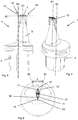
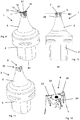
- Figs. 1-5 shows a cutting tool 1 according to a first embodiment comprising a tool body 3 and a cutting insert 2.
- the tool body 3 is shown in Fig. 1 without the cutting insert 2.
- the cutting tool comprises an insert seat 6 which is shown in Fig. 3 .
- the cutting tool 1 is a turning tool, comprising a coupling portion 4, an intermediate portion 5 and a cutting portion 2.
- the coupling portion 4 and the intermediate portion 5 are permanently connected and jointly form a tool body 3 made from steel.
- the cutting portion 2 is in the form of a first cutting insert 2 made from cemented carbide.
- the cutting tool 1 according to the first embodiment comprises only one cutting insert.
- the coupling portion 4 is suitable to a rotatable machine interface (not shown).
- the coupling portion 4 comprise a substantially conical or tapered portion 39 and a ring shaped portion 40 in accordance to ISO 26623-1:2014.
- a front end 20 or a forward end of the tool body 3 is defined by a first insert seat 6 for the first cutting insert 2.
- the first cutting insert 2 is detachably clamped in the first insert seat 6 by clamping means 14, said clamping means being in the form of a clamping screw 14.
- the first cutting insert 2 comprises a bottom surface 8 opposite a top surface 7.
- a side surface 9 connects the top and bottom surfaces 7, 8.
- a mid-plane M1 extends mid-way between the top and bottom surfaces 7, 8.
- the intermediate portion 5 extends between the coupling portion 4 and the cutting portion 2.
- a longitudinal center axis of the coupling portion 4 defines a tool rotational axis R1.
- the intermediate portion 5 extends along a longitudinal center axis A1 thereof.
- the longitudinal center axis A1 is co-linear or co-axial with the tool rotational axis R1, as seen in Figs. 2 , 4 and 5 .
- the mid-plane M1 is perpendicular to the longitudinal center axis A1 of the intermediate portion 5, and perpendicular to the rotational axis R1.
- the top surface 7 of the first cutting insert 2 is facing away from the coupling portion 4.
- the top surface 7 is non-planar, and comprises chip breaking means or chip breakers, in the form of protrusions.
- the first cutting insert 2 comprises a first and a second nose portion 10, 10', which each form free ends of the cutting tool 1,
- the first nose portion 10 comprising a first cutting edge 11, a second cutting edge 12, both straight in a top view, and a convex nose cutting edge 13 connecting the first and second cutting edges 11, 12.
- the convex nose cutting edge 13 is convex in a top view.
- the nose cutting edge 13 is in top view convexly curved having a radius of curvature of 0.15 - 1.3 mm.
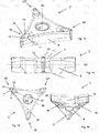
- a top view of the cutting tool according to the first embodiment is not shown, a top view of the first cutting insert 2 according to the first embodiment is shown in Fig. 8 which show an identical cutting insert.
- the radius of curvature is 0.4 mm.
- the first and second cutting edges 11, 12 forms a nose angle which is 35°.
- the first and second nose portions 10, 10' form an angle of 180° relative to each other measured around the longitudinal center axis A1 of the intermediate portion 5.
- the first cutting insert 2 is 180° symmetrical symmetric in top and bottom views.
- the first cutting insert is in a top view parallelogram-shaped.
- the first insert seat 6 comprises first insert seat rotational locking means comprising ridges 23-26, where two ridges 23, 26 are co-linear, and two ridges 24, 25 are parallel.
- the first cutting insert 2 comprises first cutting insert rotational locking means in the form of grooves (not shown), formed in the bottom surface 8, co-operating with the first insert seat rotational locking means 23-26.
- the first cutting insert 2 comprises a hole for the clamping screw 14. Said hole 13 intersects the top and bottom surfaces 8, 9, and a center axis thereof defines a first cutting insert center axis co-linear with the rotational axis R1 and the longitudinal center axis A1.
- the cutting tool 1 comprising a coolant channel formed in the tool body 3 and extending between the coupling portion 4 and a nozzle 28.
- Said nozzle 28 is formed in the intermediate portion 5, and the coolant channel and the nozzle 28 are arranged to direct a coolant fluid towards the first and second nose portions 10, 10'.
- a first extension line 21 co-linear with the first cutting edge 11 and a second extension line 22 co-linear with the second cutting edge 12 extends on opposite sides relative to the first cutting insert center axis A2, which axis is co-linear with the rotational axis R1 and the longitudinal center axis A1 when the cutting insert 2 is mounted in the insert seat 6.
- the previous sentence is true also for the cutting tool 1 according to the first embodiment.
- the first cutting insert 2 comprises three nose portions 10, 10', 10".
- the first cutting insert 2 is 120° symmetrical in top and bottom views.
- the first and second cutting edges 11, 12 forms a nose angle ⁇ which is 35°.
- the first insert seat 6 comprises first insert seat rotational locking means comprising ridges 23-25, where said ridges 23-25 extend radially in relation to a hole 32 for the clamping screw 14 formed in the first insert seat 6.
- the first cutting insert 2 comprises first cutting insert rotational locking means comprising grooves 16-18 formed in the bottom surface 8, co-operating with the first insert seat rotational locking means 23-26.
- the cutting tool 1 according to the fourth embodiment principally differs from the cutting tool 1 according to the first embodiment in that the cutting tool 1 comprises a second and a third cutting insert 29, 30, clamped our mounted in a second and third insert seat, respectively.
- Said second and third insert seats are formed in the intermediate portion 5 of the tool body 3 longitudinally between and spaced apart from the first cutting insert 2 and the coupling portion 4.
- the second cutting insert 29 and the third cutting insert 30 is each different in shape in a top view compared to the first cutting insert 2.
- the third cutting insert 30 is a threading insert.
- the second and third cutting insert 29, 30 each comprises nose portions, where each of said nose portions comprises a set of cutting edges.
- the second and third cutting inserts 29, 30 are placed at a greater distance from the longitudinal center axis A1 of the intermediate portion 5.
- the second and third cutting inserts 29, 30 forms equally large angles or substantially equally large angles in relation to the first and second nose portions.
- the first cutting insert comprise two nose portions 10, 10' which are placed at 6 o'clock and at 12 o'clock, respectively.
- the second cutting insert 29 is placed at 9 o'clock
- the third cutting insert 30 is placed at 9 o'clock, where the time references refers to an analogue 12-hour watch and relates to the relative position in relation to the longitudinal center axis A1.
- the second and third cutting inserts 29, 30 are positioned longitudinally at equal distances or substantially equal distances from the clamping portion 4.
- the cutting tool 1 according to the second embodiment principally differs from the cutting tool 1 according to the first embodiment in that for the cutting tool 1 according to the second embodiment, the longitudinal center axis A1 is parallel to and spaced apart from the tool rotational axis R1, and the convex nose cutting edge 13 of the first nose portion 10 intersects or substantially intersects the tool rotational axis R1.
- the intermediate portion 5 is offset in relation to the tool rotational axis R1.
- a mid-point of the convex nose cutting edge 13 of the first nose portion 10 is positioned less than or equal to 0.5 mm from the tool rotational axis R1.
- the cutting tool 1 according to the second embodiment is similar to the cutting tool 1 according to the first embodiment.
- a first extension line 21 co-linear with the first cutting edge 11 and a second extension line co-linear with the second cutting edge 12 extends on opposite sides relative to the longitudinal center axis A1 of the intermediate portion 5.
- the intermediate portion 5 and the first cutting insert 2 is inside an outer boundary line of the coupling portion 4.
- the second embodiment cutting tool 1 is provided, although any of the described embodiments may be used.
- the cutting insert 2 comprises first and second nose portions 10, 10'.
- the second nose portion 10' is in an active position.
- the method can alternatively be performed where the first nose portion 10 is in an active position.
- the cutting tool 1 is 180° rotated around the tool rotational axis R1.
- a metal work piece 31 is provided, which rotates around a work piece rotational axis R2.
- the tool rotational axis R1 is perpendicular to the work piece rotational axis R2.
- the work piece rotational axis R2 is in a horizontal position and the tool rotational axis R1 is in a vertical position.
- One possible alternative is to arrange the work piece rotational axis R2 is in a vertical position and the tool rotational axis R1 in a horizontal position.
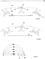
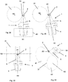
- the method comprises the step of making a first pass 36 by moving the cutting tool 1, seen in top view, such that the first cutting edge 11' is active, such that the second cutting edge 12' is inactive, and such that a machined surface 38 is formed by the nose cutting edge 13'.
- the start of the first pass 36 is shown in Fig. 21 .
- the end or the finish of the first pass is shown in Fig. 22 .
- the method comprises the step of making a second pass 37 by moving the cutting tool 1 such that the first cutting edge 11' is inactive, such that the second cutting edge 12' is active, and such that at least a portion of a machined surface 38 from the first pass 36 is machined, where the second pass is longitudinally or radially opposite or substantially opposite to the first pass.
- the start of the second pass 37 is shown in Fig. 23 .
- the end or the finish of the second pass is shown in Fig. 24 .
- the second pass is longitudinally opposite to the first pass.
- said first pass is linear.
- said first pass can be defined by a component 32 which is parallel to the work piece rotational axis R2, i.e. along the work piece rotational axis R2.
- said second pass is linear.
- said second pass can be defined by a component 33 which is parallel to the work piece rotational axis R2 and opposite to the component 32 for the first direction.
- the start and end position for the first pass 36 are spaced apart.
- an entering angle is constant.
- the cutting tool 1 is withdrawn from the metal work piece 31.
- the cutting tool 1 is rotated around the tool rotational axis R1 by an angle which is in the range of 40° - 130°.
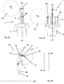
- Figs. 25-26 show a second turning method using a cutting tool according to the third embodiment. Only the cutting insert 2 is shown.
- the method can be used using a cutting tool according to any other embodiment.
- a metal work piece 31 is provided, which rotates around a work piece rotational axis R2.
- the tool rotational axis (not shown) is perpendicular to the work piece rotational axis R2.
- the method comprises the step of making a first pass, shown in Fig. 25 , by moving the cutting tool such that the first cutting edge 11 is active, such that the second cutting edge 12 is inactive, and such that a machined surface 38 is formed by the nose cutting edge 13.
- the method comprises the step of making a second pass, shown in Fig. 26 , by moving the cutting tool such that the first cutting edge 11 is inactive, such that the second cutting edge 12 is active, and such that at least a portion of a machined surface 38 from the first pass is machined.
- the cutting tool rotates in a first direction, counterclockwise in Fig. 25 , around the tool rotational axis.
- the cutting tool rotates in a second direction around the tool rotational axis, where said second direction, clock-wise in Fig. 26 , is opposite to said first direction.
- the first pass comprises a longitudinal component 32 which is towards the left-hand side.
- the second pass as seen in Fig. 26 , the cutting tool is moved along a non-linear or curved line.
- the second pass comprises a longitudinal component 33 which is towards the right-hand side, i.e. opposite to the longitudinal component 32 of the first pass.
- an entering angle is constant. After the first pass but prior to the second pass, the cutting tool is withdrawn from the metal work piece 31.
- FIG. 27 show a third turning method. Any turning tool embodiment can be used.
- a first and second pass 36, 37 is shown. Said first and second passes 36, 37 are similar or substantially similar to the second turning method. The first and second passes 36, 37 are repeated in order to progressively cut a predefined feature into the metal work piece.
- the third turning method comprises a series of alternating passes of the cutting tool, where subsequent passes are in opposite or substantially opposite directions.
- the cutting tool 1 comprises a coupling portion 4 clamped to a machine interface 40 of a CNC-lathe (not shown), an intermediate portion 5 and a cutting portion 2 in the form of a cutting insert.
- a longitudinal center axis of the coupling portion 4 defines a tool rotational axis R1.
- the intermediate portion 5 extends along a longitudinal center axis A1 thereof.
- the cutting portion 2 comprises a top surface facing away from the coupling portion 4.
- the metal work piece 31 rotates around a work piece rotational axis R2 in a clock-wise direction in Fig.
- the tool rotational axis R1 is perpendicular to the work piece rotational axis R2.
- the tool rotational axis R1 is arranged such that a tangent line of the metal work piece 31 at the point of contact with the convex nose cutting edge 13 intersect the coupling portion 4.
- the tangential cutting force is directed towards the machine interface 40.
- the tool rotational axis R1 is spaced apart by a distance from a peripheral surface of the metal work piece 31.
- the tool rotational axis R1 is parallel to said tangent line. Attention is now drawn to Fig. 29 , showing the relative position and orientation of a metal work piece 31 and a cutting tool 1 according to the third embodiment.
- the arrangement in Fig. 29 differs from Fig.
- Fig. 30 showing a side view of the center position of the cutting insert 2 from Figs. 25 and 26 , including the cutting tool 1.
- Fig. 31 showing a perspective view of the arrangement shown in Fig. 28 .
- the metal work piece 31 shown is cylindrical and comprises a lateral surface 31, i.e. a surface facing away from the work piece rotational axis R2, and a base surface 42, i.e. a surface facing in a direction parallel to the work piece rotational axis R2.
- the metal work piece 31 comprises a second base surface, facing away from the viewer.
- machining is made in a lateral surface 41 of a metal work piece 31.
- material is removed by metal cutting from said lateral surface 41.
- machining is made in a base surface 42 of a metal work piece 31.
- Figs. 32 and 33 showing a fourth turning method, using the cutting tool 1 according to the fourth embodiment.
- the method includes any of the above described turning methods, using the first cutting insert 2, where the cutting tool 1 according to the fourth embodiment is in a position relative to the metal work piece 31 as shown in Fig. 32 .
- the method further comprises the steps of withdrawing the cutting tool 1 from the metal work piece 31, and moving the cutting tool 1 in a forward direction along the tool rotational axis R1 to the position shown in Fig. 33 .
- the method further comprises the step of rotating the cutting tool 1 around the tool rotational axis R1 by a predetermined angle, such that the second cutting insert 29 is in an active position.
- Fig. 34 showing a fifth turning method using the second embodiment cutting tool 1 is provided, although any of the described embodiments may be used.
- a metal work piece 31 is provided, which rotates around a work piece rotational axis R2.
- the tool rotational axis R1 is perpendicular to the work piece rotational axis R2.
- the machining in the fifth turning method is made at a base surface of the metal work piece 31.
- the tool rotational axis R1 is perpendicular to the work piece rotational axis R2. In the example, both the work piece rotational axis R2 and the tool rotational axis R1 is in a horizontal position.
- the cutting insert 2 comprises first and second nose portions 10, 10'.
- the second nose portion 10' is in an active position.
- the method can alternatively be performed where the first nose portion 10 is in an active position.
- the cutting tool 1 is 180° rotated around the tool rotational axis R1.
- the method comprises the step of making a first pass 36 by moving the cutting tool such that the first cutting edge 11' is active, such that the second cutting edge 12' is inactive, and such that a machined surface is formed by the nose cutting edge 13'.
- the method comprises the step of making a second pass 37 by moving the cutting tool such that the first cutting edge 11' is inactive, such that the second cutting edge 12' is active, and such that at least a portion of a machined surface from the first pass 37is machined.
- the cutting tool rotates in a first direction, counterclockwise in Fig. 34 , around the tool rotational axis R1.
- the cutting tool rotates in a second direction around the tool rotational axis, where said second direction, clock-wise in Fig. 34 , is opposite to said first direction.
- the cutting tool is moved along non-linear or curved path.
- the first pass comprises a radial component 34 which is perpendicular to and towards the work piece rotational axis R2, downwards in Fig. 34 .
- the second pass 37 the cutting tool is moved along a path which is non-linear or curved.
- the second pass comprises a radial component 35 which is perpendicular to and away from the work piece rotational axis R2, upwards in Fig. 34 , i.e. opposite to the radial component 34 of the first pass.
- an entering angle is constant.
- the cutting tool is withdrawn from the metal work piece 31.
Landscapes
- Engineering & Computer Science (AREA)
- Mechanical Engineering (AREA)
- Turning (AREA)
- Auxiliary Devices For Machine Tools (AREA)
- Cutting Tools, Boring Holders, And Turrets (AREA)
Abstract
Description
- The present invention belongs to the technical field of metal cutting. More specifically the present invention belongs to the field of cutting tools for turning of a metal work piece, by use of computer or computerized numerical control, i.e. CNC, machines.
- In particular, the present invention relates to a cutting tool for turning, comprising a coupling portion, an intermediate portion and a cutting portion, the intermediate portion extending between the coupling portion and the cutting portion, the intermediate portion extending along a longitudinal center axis thereof, the cutting portion comprising a first and a second nose portion, the first and second nose portions being permanently connected, the first nose portion comprising a first cutting edge, a second cutting edge, and a convex nose cutting edge connecting the first and second cutting edges, and the first and second cutting edges forming a nose angle less than 90°.
- In turning of metal work pieces using a CNC-lathe, it is common to use a plurality of cutting tools in order to machine a component having a predefined shape. The predefined shape of the component may vary considerably, and may include different features such as a slot or a groove.
In machining of components, it is a desire to reduce the machining time. One way to reduce the machining time is to reduce the time for tool change.
EP1158378B1 claims to provide a machine tool capable of machining in a plurality of machining modes with a single tool, wherein the loss of machining time due to tool change can be decreased and the number of tools to be prepared can be decreased. A conventional tool is provided comprising a cutting insert, comprising two opposite nose portions of around 55° nose angle, mounted in a tool body, such that one nose portion is a free end and thereby in an active or usable position. A slot machining (tool positions 25F, 25G inFig. 7 ) is shown. A so called B-axis can be set to a number of angles. - The inventor has found that although many conventional tools can be replaced by using the above described conventional tool in the above described method, there is a need for an improved cutting tool.
- The inventor has found that there is a need for an improved turning tool which can used in an improved method. For example, when machining a slot using the above described method and tool, the degree of B-angle adjustment possible is limited because of geometrical factors, especially the depth and width of the slot. For a relatively deep and narrow slot, there is an increased risk of interference between the tool body and the work piece. A further need for improvement which the inventor has found relates to the risk of vibrations, especially if cutting tools having a great overhang is used, such as in deep slot turning. A still further need for improvement relates to reducing the down-time for a CNC-machine.
- An object of the present invention is to provide an improved turning tool. This is achieved by the cutting tool according to
claim 1. In other words, this is achieved by the initially defined cutting tool, which is characterized in that a longitudinal center axis of the coupling portion defines a tool rotational axis, the intermediate portion extending along a longitudinal center axis thereof, the longitudinal center axis being parallel to or co-linear with the tool rotational axis, the cutting portion comprising a top surface, the top surface is facing away from the coupling portion, the first and the second nose portions each form free ends of the cutting tool, in that in a top view, the first and second nose portions form an angle of more than 90° relative to each other measured around the longitudinal center axis of the intermediate portion, and in that in a top view, a first extension line co-linear with the first cutting edge and a second extension line co-linear with the second cutting edge extends on opposite sides relative to the longitudinal center axis of the intermediate portion. - By such a cutting tool, accessibility is improved such that a relatively narrow pocket can be machined. By such a cutting tool, the risk of vibrations is reduced and the risk of deflection of the cutting tool is reduced. By such a cutting tool, it is possible to turn in a first direction using the first cutting edge, rotate the tool around the tool rotational axis, and turn in the opposite direction using the second cutting edge, thereby reducing the machining time. By such a cutting tool, the indexing time is reduced, because change from a used first nose portion in an active position to a second new nose portion in an active position can be made in a short time. Conventionally in turning, indexing is made manually and involves the steps of removing the cutting insert from the insert seat and replacing the worn cutting insert with a new cutting insert. Alternatively, change to a new nose portion can be made by an automatic or manual step which involves removing, i.e. un-clamping, the used cutting tool from the machine interface. Compared to the above described conventional methods using a conventional cutting tool, the present cutting tool provides a less time-consuming option.
- The cutting tool is suitable for turning metal work pieces. In other words, the cutting tool is a turning tool which can be used for cutting a rotating metal work piece. The cutting tool comprising a coupling portion is suitable to be connected directly, or by one or more tool devices, to a rotatable machine interface, e.g. a spindle, of a machine tool which can be used for turning, such as e.g. a turning lathe, a multi task machine, a turn-mill machine, or a sliding head machine. The machine tool is preferably a CNC-machine, i.e. computer or computerized numerical control, machine. The coupling portion preferably comprise a conical or substantially conical portion and a ring-shaped portion, such as preferably in the form of a polygonal hollow taper interface with a flange contact surface, such in accordance to ISO 26623-1:2014, or a hollow taper with a flange contact surface such as in accordance to DIN 69893, ISO 12164-1 or ISO 12164-1F.
- The conical portion and the ring-shaped portion are preferably concentric.
In relation to the conical portion, the ring-shaped portion preferably extends a greater radial distance in relation to the tool rotational axis.
A longitudinal center axis of the coupling portion defines a tool rotational axis. In other words, when the coupling portion is mounted in the machine interface, e.g. the machine spindle, the cutting tool is rotatable around the tool rotational axis. In other words, the cutting tool is arranged to be rotatable around the tool rotational axis.
The tool rotational axis is a longitudinal center axis of the coupling portion.
The cutting tool is arranged to be rotatable around a tool rotational axis thereof.
The coupling portion is preferably arranged symmetrically or substantially symmetrically around the tool rotational axis.
The coupling portion is preferably permanently connected to the intermediate portion, thereby forming a tool body.
The coupling portion and the intermediate portion are preferably made from steel.
The intermediate portion extends between and connects the coupling portion and the cutting portion.
The intermediate portion extends along a longitudinal center axis thereof.
The intermediate portion is preferably arranged symmetrically or substantially symmetrically around the longitudinal center axis thereof.
In cross sections perpendicular to the rotational axis, the intermediate portion preferably is greater in size, i.e. has a larger area at a rear end thereof, i.e. at the intersection between the coupling portion and the intermediate portion, than at a front end thereof, i.e. at the intersection between the intermediate portion and the cutting portion.
The longitudinal center axis being parallel to or co-linear, i.e. co-axial, with the tool rotational axis. The longitudinal center axis being parallel to the tool rotational axis means that the longitudinal center axis is spaced apart from the tool rotational axis. - The cutting tool comprises a cutting portion. The cutting portion defines a front end of the cutting tool. The coupling portion defines a rear end of the cutting tool. The cutting is preferably in the form of a cutting insert made from a hard and wear resistant material such as e.g. cemented carbide, cermet, cubic boron nitride (CBN) or ceramic. The cutting insert is preferably detachably mounted in an insert seat formed in a front end of the intermediate portion.
Alternatively, the cutting portion, the coupling portion and the intermediate portion is a singular body.
The cutting portion comprising a top surface comprising a rake face.
The top surface is facing away from the coupling portion.
The cutting tool is preferably elongated in the direction of the longitudinal center axis of the intermediate portion, such that a distance from the top surface to the clamping portion is greater than a maximum diameter of the cutting tool measured in a plane perpendicular to the longitudinal center axis of the intermediate portion.
The cutting portion comprises a first and a second nose portion. A nose portion can alternatively be designated as a corner portion.
The first and second nose portions are permanently connected to each other. Preferably, the first and second nose portions are in the form of nose portions of one cutting insert.
The first nose portion comprises a first cutting edge, a second cutting edge, and a convex nose cutting edge connecting the first and second cutting edges.
The nose cutting edge is in top view preferably convexly curved, such as a circular arc having a radius of curvature of 0.15 - 1.3 mm, even more preferably 0.3 - 0.9 mm. Alternatively, the nose cutting edge may in top view have a convex shape, which convex shape deviates from a perfect circular arc, such as a shape which comprises two or more circular arcs having different radii of curvature. For example, the nose cutting edge may be a so-called wiper nose cutting edge. - Preferably, the nose cutting edge is the most distal portion of the cutting portion in relation to the longitudinal center axis of the intermediate portion.
The top surface preferably comprises chip breaking means, preferably in the form of one or more protrusions, preferably located in the vicinity of i.e. less than 3 mm from the nose cutting edge.
The first and second cutting edges are each in a top view preferably straight or substantially straight. Preferably, in a top view a bisector formed mid-way between the first and second cutting edges intersects the longitudinal center axis of the intermediate portion.
Preferably, the second nose portion comprises a convexly curved nose cutting edge, such that the convexly curved nose cutting edges of the first and second nose portion, respectively, being positioned in a common plane perpendicular to the tool rotational axis.
The first and second cutting edges in a top view forms a nose angle which is less than 90°, preferably 15° - 85°, even more preferably 20° - 40°.
The first and the second nose portions each form free ends of the cutting tool. The first and the second nose portions each form radially outer portions of the cutting portion, where radially outer refers to the longitudinal axis of the intermediate portion. Formulated differently, the first and the second nose portions comprises radially outer end portions of the front end of the cutting tool.
The first and the second nose portions are arranged to be alternatively active.
The first and second nose portions form radially distal portions of the front end of the cutting tool, where said radial distances is in relation to the longitudinal center axis of the intermediate portion.
The first and second nose portions are preferably located at equal distances from the longitudinal center axis of the intermediate portion.
Alternatively, said distances may vary, preferably by less than 30 %, even more preferably by less than 10 %. - The first and second nose portions may preferably be formed in a corresponding manner. Alternatively, the second nose portion may be arranged differently, i.e. having a different shape or chemical composition, compared to the first nose portion, e.g. having a different shape in a top view and/or comprising a nose cutting edge having a curvature which in a top view differs from a curvature of nose cutting edge of the first nose portion.
In a top view, where the top surface of the cutting portion is facing the viewer, the first and second nose portions form an angle of more than 90°, preferably 120° or 180°, relative to each other, measured around the longitudinal center axis of the intermediate portion.
In a top view, a first extension line co-linear with the first cutting edge and a second extension line co-linear with the second cutting edge extends on opposite sides relative to the longitudinal center axis of the intermediate portion. Preferably, in a top view an extension of a bisector formed between the first and second cutting edges intersect the longitudinal center axis of the intermediate portion.
Preferably, in a top view the cutting portion is inside a circle having a diameter of 50 mm, more preferably inside a circle having a diameter of 35 mm.
Preferably, the cutting tool has a length measured along or parallel to the tool rotational axis which is 80 - 400 mm, more preferably 90 - 250 mm.
Preferably, the cutting tool has a maximum diameter, measured perpendicular to the tool rotational axis, which is less than the said length of the cutting tool, preferably 0.2 - 0.8 times said length.
Preferably, the length of the coupling portion measured along or parallel to the tool rotational axis is less than the length of the intermediate portion.
Preferably, the length of the cutting portion measured along or parallel to the tool rotational axis is less than the length of the intermediate portion, more preferably less than 15 % of the length of the intermediate portion. - According to an embodiment, the coupling portion and the intermediate portion jointly form a tool body, wherein the cutting portion being in the form of a first cutting insert, wherein a front end of the tool body is defined by a first insert seat for the first cutting insert, wherein the first cutting insert is detachably clamped in the first insert seat by clamping means, wherein the first cutting insert comprising a bottom surface opposite the top surface, wherein a side surface connects the top and bottom surfaces, wherein a mid-plane extends mid-way between the top and bottom surfaces, and wherein the nose cutting edge is in top view convexly curved having a radius of curvature of 0.15 - 1.3 mm.
- By such a cutting tool, only the cutting portion in the form of the first cutting insert needs to be replaced after use, thereby making the cutting tool more economical.
- The cutting tool comprises a first cutting insert, preferably made from a hard and wear resistant material suitable for metal cutting, such as preferably cemented carbide. The cutting tool comprises a tool body, preferably made from a comparably less wear resistant material such as e.g. steel. The tool body comprises the coupling portion and the intermediate portion. The coupling portion and the intermediate portion are permanently connected, thereby forming the tool body in the form of a singular body.
The tool body extends longitudinally between a rear end, defined by the clamping portion, and a front end defined by a first insert seat, or insert pocket, for the first cutting insert.
The first cutting insert is detachably or removably clamped or locked in the first insert seat by clamping means, e.g. by means of one or more screws. - The first cutting insert comprises a bottom surface opposite the top surface. The top surface comprises a rake face. A side surface connects the top and bottom surfaces. The side surface comprises a clearing surface. The first, second and nose cutting edges are formed at intersections between the side surface and the top surface.
A mid-plane extends mid-way between the top and bottom surfaces.
The first cutting insert may be mirror-symmetric in relation to the mid-plane. In other words, the first cutting insert may be a so called negative cutting insert.
Preferably, an area of the top surface is greater than an area of the bottom surface, where said areas are defined as the area inside the outer boundary lines of said surfaces. In other words, preferably the first cutting insert is a positive cutting insert. Such an insert gives an improved clearance.
Preferably, the top and bottom surfaces are shaped such that the shapes thereof corresponds or substantially corresponds to each other. For example, if the top surface is generally triangular-shaped, the bottom surface is preferably triangular shaped. Other suitable shapes include a rhombic shape.
The nose cutting edge is in top view convexly curved having a radius of curvature of 0.15 - 1.3 mm. In other words, in a top view the nose cutting edge is arc-shaped. The nose cutting edge may in top view have a shape of a circular arch. Alternatively, the nose cutting edge may in top view have a shape which is arch-shaped but deviates from a perfect circular arch, such as e.g. a shape commonly known as a wiper nose radius or a wiper radius or a wiper design.
In a top view, the first and the second nose portions preferably extend radially outside a front end of the intermediate portion, i.e. outside the insert seat.
The front end of the intermediate portion, i.e. the front end of the tool body, consists of exactly one insert seat. - According to an embodiment, the mid-plane is perpendicular to the longitudinal center axis of the intermediate portion.
- By such a cutting tool, alternating between the first and second nose portions can be made such that the cutting performance is unchanged, e.g. with regards to cutting forces, especially if the insert is 120° or 180° symmetrical in a top view. The first and second nose portions are preferable formed in a corresponding manner. The alternating between the first and second nose portions can preferably be made by rotating the cutting tool around the rotational axis thereof by a predetermined angle, such as 120° or 180°. Said rotating is preferably made as the cutting insert is inactive. Alternating between the first and second nose portions means alternatively positioning the first and second nose portion in an active position. An active position of a nose portion is between the work piece to be machined and the longitudinal center axis of the intermediate portion.
- The mid-plane being perpendicular to the longitudinal center axis of the intermediate portion, and thus also perpendicular to the rotational axis.
- According to an embodiment, the first insert seat comprises first insert seat rotational locking means, and wherein the first cutting insert comprises first cutting insert rotational locking means co-operating with the first insert seat rotational locking means.
- By such a cutting tool, the risk of rotating the cutting insert around an axis parallel to the rotational axis is reduced. In other words, the risk of movement of the cutting insert relative to the insert seat is reduced.
- The first insert seat comprises first insert seat rotational locking means, i.e. rotational preventing means, preferably in the form of one or more grooves or ridges. Preferably, said one or more grooves or ridges extends in a direction corresponding to a bisector formed between the first and second cutting edges. Preferably, said at least one or more grooves or ridges includes one or more inclined surfaces, functioning as contact or support surfaces, and such that said one or more inclined surfaces is inclined, preferably by an angle of 5 - 70°, in relation to a plane perpendicular to the rotational axis.
The first cutting insert preferably comprises first cutting insert rotational locking means, or rotation preventing means, formed in the bottom surface, preferably in the form of one or more protrusions or recesses, even more preferably in the form of one or more grooves or ridges.
Preferably, said one or more grooves or ridges extends in a direction corresponding to a bisector formed between the first and second cutting edges. Preferably, said at least one or more grooves or ridges includes one or more inclined surfaces, functioning as contact or support surfaces, and such that said one or more inclined surfaces is inclined, preferably by an angle of 5 - 70°, in relation to a plane perpendicular to the mid-plane.
Said co-operating rotational locking means may preferably be arranged such that the bottom surface of the first cutting insert comprises two parallel and spaced apart grooves, extending on opposite sides of a cutting insert center axis, and further at least one perpendicular groove extending along the bisector or bisectors of the acute corner or corners of the cutting insert. Said bottom surface is preferably arranged according to or substantially similarly as described inEP1702703A1 , even more preferably as described in paragraph [0018] and shown inFig. 5 inEP1702703A1 . The insert seat preferably comprises ridges arranged in a corresponding manner. - Alternatively, said co-operating rotational locking may be arranged such that the side surface of the cutting insert comprises one or more contact surfaces, wherein the insert seat comprises one or more protrusions, and wherein said one or more protrusions is in contact with at least one of said contact surfaces. Relative to a bottom surface of the insert seat, said one or more protrusions extend away from the connecting portion.
- According to an embodiment, the first cutting insert rotational locking means are formed in the bottom surface of the first cutting insert.
- By such a cutting tool, the accessibility is further improved. For example, a cavity or pocket having a narrow width can be machined using such cutting tool.
- The bottom surface of the cutting insert is non-flat. The rotational locking means formed in the bottom surface are in the form of one or more recesses or protrusions, preferably in the form of one or more grooves or ridges.
- According to an embodiment, the top surface comprising chip breaking or chip forming means in the form of one or more protrusions and/or depressions.
- By such a cutting tool, the chip control and/or chip breaking is improved in a turning operation.
- Preferably, the top surface of the first nose portion comprises a protrusion which in a top view is symmetrical or substantially symmetrical in relation to a bisector formed between the first and second cutting edges. Preferably, the top surface comprises a protrusion which extends beyond a plane, parallel to the mid-plane, comprising the nose cutting edges. In other words, said protrusion extends in a direction away from the mid-plane. Said protrusion is spaced apart from the side surface.
- According to an embodiment, the first cutting insert is 180° or 120° symmetrical or substantially symmetrical in a top view.
- By such a cutting tool, the cutting tool can be used for a longer time without changing the cutting insert.
The first cutting insert may be single-sided. Alternatively, the first cutting insert may be double-sided, such that the top and bottom surfaces are alternatingly useable. - Preferably, the first cutting insert in a top view comprises at least two but not more than three nose portions.
Preferably, a bisector extending between the first and second cutting edges intersects the longitudinal center axis. - According to an embodiment, the clamping means is in the form of a clamping screw, wherein the first cutting insert comprises a hole for the clamping screw, wherein the hole intersects the top and bottom surfaces, wherein the hole defines a first cutting insert center axis, wherein the first cutting insert center axis is co-linear with the rotational axis, and wherein the longitudinal center axis being co-linear with the tool rotational axis.
- By such a cutting tool, an indexing of the first cutting insert can be made in a less complicated way if the first cutting insert is inside a narrow cavity or a narrow pocket. Indexing in this context is made through rotation of the cutting tool around the rotational axis thereof by an angle, preferably 120° or 180°, such that one cutting portion is positioned in an active position.
- Thus, the clamping of the cutting insert to the insert seat is achieved by means of a clamping screw. The first cutting insert comprises a hole, intersecting the top and bottom surfaces, through which hole the clamping screw extends. The tool body comprises a threaded hole, co-linear with the first cutting insert center axis, which intersects the insert seat.
The nose cutting edges are spaced apart from the tool rotational axis. - According to an embodiment, the longitudinal center axis being parallel to and spaced apart from the tool rotational axis, and wherein the convex nose cutting edge intersects or substantially intersects the tool rotational axis.
- By such a cutting tool, the position for the convex nose cutting edge can be determined in a more convenient manner, thereby making programming of a CNC-lathe easier.
By such a cutting tool, a deeper pocket can be machined because the risk of interference is reduced, when using the second nose portion, especially if the first and second nose portions in a top view form an angle of 180° or substantially 180°. - The convex nose cutting edge intersects or substantially intersects the tool rotational axis. Substantially intersects in this context shall be interpreted such as a mid-point of the convex nose cutting edge is positioned within 0.5 mm from the tool rotational axis.
- According to an embodiment, in a top view the intermediate portion is inside an outer boundary line of the coupling portion.
- By such a cutting tool, the accessibility is further improved. By such a cutting tool, an indexing of the first cutting insert can be made in a less complicated way if the first cutting insert is inside a narrow cavity or a narrow pocket.
- In a top view the intermediate portion is inside an outer boundary line of the clamping portion. In other words, a maximum distance from the tool rotational axis to the intermediate portion is equal to or preferably less than a maximum distance from the tool rotational axis to the coupling portion.
In a top view, preferably the cutting insert is inside an outer boundary line of the coupling portion. - According to an embodiment, the cutting tool comprising a coolant channel, wherein the coolant channel extends between the coupling portion and a nozzle, wherein the nozzle being formed in the intermediate portion, and wherein the coolant channel and the nozzle being arranged to direct a coolant fluid towards the first nose portion.
- By such a cutting tool, the wear of the cutting edges may be reduced.
- The cutting tool comprises a coolant channel, extending between a coolant channel inlet, formed in the coupling portion, and a coolant channel outlet, i.e. a nozzle. The coolant channel inlet is preferably arranged concentric with the tool rotational axis. The nozzle opens into an external surface of the intermediate portion. The nozzle being positioned longitudinally between the cutting insert and the coupling portion.
The coolant channel and the nozzle are arranged such that a coolant fluid is directed towards the first nose portion, preferably towards a point or an area which is within 2.0 mm from the convex nose cutting edge. - According to an embodiment, the cutting tool comprises a second cutting insert clamped in a second insert seat, wherein the second insert seat is formed in the intermediate portion of the tool body, wherein the second insert seat is positioned longitudinally between and spaced apart from the first cutting insert and the coupling portion.
- By such a cutting tool, the time for machining a component can be further reduced, because the change from the first cutting insert to the second cutting insert can be made in a short time.
- The cutting tool, more precisely the tool body, comprises a second cutting portion in the form of a second cutting insert clamped or removably fastened, preferably by means of a clamping screw, in a second insert seat.
Preferably, the second cutting insert is different in shape in a top view compared to the first cutting insert. For example, the second cutting insert may be a threading insert or a grooving insert, while the first cutting insert is a turning insert.
The second insert seat is formed in the intermediate portion of the tool body longitudinally between and spaced apart from the first cutting insert and the coupling portion. In other words, the second insert seat is placed rearward of the first insert seat.
Preferably, the second cutting insert is removably fastened in the second insert seat such that at least one nose portion of the second insert is positioned compared to the first nose portion is placed at a greater distance from the longitudinal center axis of the intermediate portion.
Preferably, the second cutting insert is removably fastened in the second insert seat such that at a second cutting insert nose portion in an active position (i.e. radially outer position) in a top view forms equally large angles or substantially equally large angles in relation to the first and second nose portions. For example, when the cutting tool is seen in top view, the first cutting insert may comprise two nose portions which are placed at 6 o'clock and at 12 o'clock, and the second cutting insert may comprise a radially outer nose portion which is placed at approximately 3 o'clock, or alternatively approximately at 9 o'clock, where the time references refers to an analogue 12-hour watch. By such a cutting tool, the clearance is further improved.
Preferably, the cutting tool comprises a third insert seat. Preferably, the third insert seat is positioned opposite or substantially opposite the second insert seat in relation to the longitudinal center axis of the intermediate portion.
Preferably, the third insert seat and the second insert seat are positioned longitudinally at equal distances or substantially equal distances from the clamping portion. - According to a further aspect, a turning method for a computerized numerical control lathe is provided comprising the steps of: providing a cutting tool according to any of the preceding claims; providing a metal work piece; rotating the metal work piece around a work piece rotational axis; setting the tool rotational axis perpendicular to or substantially perpendicular to the work piece rotational axis; making a first pass such that the first cutting edge is active and such that the second cutting edge is inactive, making a second pass such that the first cutting edge is inactive and such that the second cutting edge is active, where the second pass is longitudinally or radially opposite or substantially opposite to the first pass; and wherein the method comprises the step of rotating the turning tool around the tool rotational axis during the first pass and/or during the second pass and/or after the first pass but prior to the second pass.
- By such a turning method, a predefined feature or a sub-portion of a predefined feature can be machined in a shorter time. For example, compared to conventional longitudinal turning using multiple passes where all passes are in the same direction, the present method is faster because there may be less movement from an end position of a first pass to a start position for a subsequent pass.
Especially, a predefined feature or a sub-portion of a predefined feature comprising a depression or a pocket or a groove can be machined in a shorter time, because only one cutting portion is necessary. The rotation of the cutting tool can be selected to provide sufficient clearance.
Further, by the rotation of the cutting tool, an entering angle can be selected freely, compared to conventional turning where the entering angle is a result of feed direction and tool design. Thus, the tool life and/or chip control can be improved.
By such a method, where the top surface of the cutting portion is facing away from the coupling portion and the tool rotational axis is perpendicular to or substantially perpendicular to the work piece rotational axis, the tangential cutting force is directed towards the machine spindle to which the coupling portion is connected. Thereby, the risk of vibration or deflection is reduced. Thereby, a deeper pocket can be machined.
By such a method, a single cutting tool can be used for machining numerous types of features, thereby reducing the need for tool inventory.
By such a method, the tool life of the cutting portion may be increased because the insert wear may be more evenly distributed along both the first and second cutting edges. - The turning method is for use by means of a computerized numerical control (CNC) lathe suitable for turning, and may be in the form of e.g. a turning lathe, a multi task machine, a turn-mill machine, or a sliding head machine. More specifically, the turning method is a machining sequence where an electronic control system controls movements, including rotations, of a cutting tool and a metal work piece in order to cut a predefined feature into a predefined location of the metal work piece.
Said predefined feature preferably comprises a pocket or a groove. Said predefined feature preferably opens into an outer peripheral surface of the metal work piece.
A metal work piece is provided. The metal work piece may be made from e.g. steel, stainless steel, a Nickel-based super alloy or Aluminum.
The metal work piece is preferably rotationally symmetrical or substantially rotationally symmetrical around a rotational axis thereof.
For example, the metal work piece may be cylindrical or substantially cylindrical.
The metal work piece comprises a peripheral surface. If the metal work piece is cylindrical, the peripheral surface comprises a lateral area or a side area (lateral area 2πrh) and top and bottom base areas (each area, also called base areas, is πr2), where r is the radius of the cylinder and h is the height of the cylinder (along the work piece rotational axis).
Even if the metal work piece is not in the form of a cylinder, we can still define a lateral surface, i.e. a surface facing away from the work piece rotational axis, and base surfaces, i.e. surfaces facing in a direction parallel to the work piece rotational axis.
The method comprises the step of rotating the metal work piece around a work piece rotational axis thereof. The metal work piece is clamped by clamping means at a clamping end thereof and the rotation is achieved by means of a motor. The CNC-lathe comprises said motor. The metal work piece rotates such that the speed of a peripheral surface of the metal work piece, is preferably 40 - 1000 m/min.
The method comprises the step of setting the tool rotational axis perpendicular to or substantially, i.e. less than 15°, perpendicular to the work piece rotational axis. The tool rotational axis and the work piece rotational axis are spaced apart.
The method comprises the step of making a first pass, by moving the cutting tool and the tool rotational axis relative to the metal work piece, such that the first cutting edge is active and is a leading edge or a main cutting edge, and such that the second cutting edge is inactive and is a trailing edge or a secondary cutting edge. The nose cutting edge is a surface generating cutting edge. The first pass creates or forms or results in a machined surface of the metal work piece.
Said first pass may be linear, i.e. along a straight line. Alternatively, said first pass may be curved or non-linear. In either case, said first pass comprises a component which preferably is an axial or longitudinal component, i.e. along the work piece rotational axis, such as longitudinal turning, or alternatively comprises a radial component, which is towards or away from the work piece rotational axis, such as facing or out-facing.
The velocity of said movement combined with the rotational speed of the metal work piece result in a feed rate for the first cutting edge, which feed rate is preferably 0.05 - 1.5 mm/revolution.
The method comprises the step of making a second pass, by moving the cutting tool and the tool rotational axis relative to the metal work piece, such that the first cutting edge is inactive and is a trailing edge or a secondary cutting edge, and such that the second cutting edge is active and is a leading edge or a main cutting edge. The nose cutting edge is a surface generating cutting edge. The second pass creates a machined surface.
Said second pass may be linear, i.e. along a straight line. Alternatively, said second pass may be curved or non-linear. In either case, said second pass comprises a component which preferably is an axial or longitudinal component, i.e. along the work piece rotational axis, such as longitudinal turning, or alternatively comprises a radial component, which is towards or away from the work piece rotational axis, such as facing or out-facing.
A start position and an end position for the first pass are spaced apart.
A start position and an end position for the second pass are spaced apart.
The velocity of said movement combined with the rotational speed of the metal work piece result in a feed rate for the second cutting edge, which feed rate is preferably 0.05 - 1.5 mm/revolution.
The second pass is longitudinally or radially opposite or substantially opposite to the first direction. For example, if the first pass or a component thereof is towards a clamping end of the metal work piece, the second pass or a component thereof is away from said clamping end of the metal work piece. In other words, the second pass is longitudinally opposite the first pass.
Another example is if the first pass or a component thereof is towards the work piece rotational axis. In such case, the second pass or a component thereof is away from the work piece rotational axis. In other words, the second pass is radially opposite the first pass.
Formulated differently, either the first and second passes are both related to cutting of the lateral surface of the metal work piece, or the first and second passes are both related to cutting of one base surfaces of the metal work piece. In the first example, the first and second passes can be longitudinal turning or profile turning operations, in opposite directions longitudinally.
In the second example, the first and second passes can be facing operations, such as in-facing and out-facing operations, respectively.
In other words, the expression "the second pass is longitudinally or radially opposite or substantially opposite to the first pass" can be understood as if the first pass comprises a longitudinal component, the second pass comprises an opposite longitudinal component, and if the first pass comprises a radial component, the second pass comprises an opposite radial component.
A second pass which is linear and radial, i.e. perpendicular to the work piece rotational axis is not considered opposite to a first pass which is linear and parallel to the work piece rotational axis, because the second pass has no component which is along the work piece rotational axis.
Preferably, a predefined feature or a sub-portion of a predefined feature formed by the first and second passes is formed completely or to a major extent in a lateral surface of the metal work piece, and in that the opposite components of the first and second direction, respectively are longitudinal.
Alternatively, a predefined feature or a sub-portion of a predefined feature formed by the first and second passes is formed completely or to a major extent in a base surface of the metal work piece, and in that the opposite components of the first and second pass, respectively are radial.
The moving of the tool rotational axis during the first and second pass, respectively, is preferably a parallel movement. In other words, the initial, intermediate and final orientations or positions of the tool rotational axis are parallel.
The first and second passes are automated cutting cycles.
The method comprises the step of rotating the turning tool around the tool rotational axis during the first pass and/or during the second pass and/or after the first pass but prior to the second pass. In other words, the method comprises a rotational movement of the turning tool around the tool rotational axis.
Said rotating of the turning tool around the tool rotational axis is, if during the first and/or second pass, is preferably synchronized with a change of the feed direction such that an entering angle is constant or substantially constant.
The step of rotating the turning tool around the tool rotational axis may be between the first pass and the second pass, i.e. after the first pass but prior to the second pass. In such a case, the turning tool rotates an angle around the tool rotational axis which is less than 360°, preferably 20° - 170°, more preferably 40° - 130°.
The step of rotating the turning tool around the tool rotational axis may alternatively be during, i.e. simultaneously, as the first pass. In such a case, the turning tool rotates an angle around the tool rotational axis which is less than 360°, preferably 5° - 180°, more preferably 10° - 170°.
The step of rotating the turning tool around the tool rotational axis may alternatively be during, i.e. simultaneously, as the second pass i.e. the step of moving the tool rotational axis in the opposite second direction. In such a case, the turning tool rotates an angle around the tool rotational axis which is less than 360°, preferably is 5° - 180°, more preferably 10° - 170°. - The step of rotating the turning tool around the tool rotational axis may alternatively be during, i.e. simultaneously, as the first and second passes. In such a case, the turning tool during the first and second passes, respectively, rotates an angle around the tool rotational axis which preferably is 5° - 180°, more preferably 10° - 170°. In such a case the direction of rotation during the first pass is opposite to the direction of rotation during the second pass. In other words, if the rotation during the first step is clock-wise, the rotation during the second step is counter clock-wise, and vice versa.
During the first and second passes, the top surface of the cutting portion functions as a rake face or a rake surface. - According to an embodiment, the turning method comprising the further steps of: withdrawing the cutting tool from the metal work piece, and rotating the cutting tool around the tool rotational axis such that the first nose portion is moved away from the metal work piece and such that the second nose portion is moved towards the metal work piece.
By such a method, the indexing time is reduced, because change from a used first nose portion in an active position to a second new nose portion in an active position can be made in a short time. Conventionally in turning, indexing is made manually and involves the step of removing the cutting insert from the insert seat. Alternatively, change to a new nose portion can be made by an automatic or manual step which involves removing the used cutting tool from the machine interface. Compared to the above described conventional methods using conventional cutting tool, the present cutting tool provides a less time-consuming option. - The method thus comprises the step of withdrawing the cutting tool from the metal work piece preferably after the second pass. The cutting tool is withdrawn by enough distance such that sufficient clearance is provided, in order to avoid an interference during the subsequent rotation. Said rotation means rotating the cutting tool around the tool rotational axis such that the first nose portion is moved away from the metal work piece and such that the second nose portion is moved towards the metal work piece. In other words, an indexing is made such that the used first nose portion is brought into an inactive position and such that a new second nose portion is brought into an active position.
Said rotation is preferably equal to or substantially equal to the angular difference in a top view between the first and second nose portions. Said rotation is preferably equal to or substantially equal to 90°, 120°, 180° or 240°.
Preferably, said method comprises the step of cutting the metal work piece, or a second metal work piece similar or substantially similar to the said metal work piece, using the second nose portion in a corresponding way as for the first nose portion.
According to an embodiment or an aspect a computer program is provided having instructions which when executed by a computer numerical control lathe cause the computer numerical control lathe to perform any of the above described turning methods.
Said computer program having instructions for controlling movement and rotation of the cutting tool, and instructions for rotation of the metal work piece, for removing stock by means of a turning operation according to any of the above defined turning methods.
Said instructions may include cutting data such as cutting speed, feed rate, tool path and cutting depth.
Said computer program may preferably be stored on a computer readable medium. - Preferably, said computer program may be represented by a data stream.
- The present invention will now be explained in more detail by a description of different embodiments of the invention and by reference to the accompanying drawings.
- Fig. 1
- is a perspective view of a tool body which is part of a cutting tool according to a first embodiment.
- Fig. 2
- is a perspective view of a cutting tool according to a first embodiment.
- Fig. 3
- is a perspective view of the insert seat of the tool body in
Fig. 1 . - Fig. 4
- is a side view of the cutting tool in
Fig. 2 . - Fig. 5
- is a further side view of the cutting tool in
Fig. 2 . - Fig. 6
- is a side view of a cutting tool according to a second embodiment.
- Fig. 7
- is a perspective view of the cutting tool in
Fig. 6 . - Fig. 8
- is a top view of the cutting tool in
Fig. 6 . - Fig. 9
- is a perspective view of a cutting tool according to a third embodiment.
- Fig. 10
- is a side view of the cutting tool in
Fig. 9 . - Fig. 11
- is a perspective view of the tool body in
Fig. 9 . - Fig. 12
- is a perspective view of the insert seat of the tool body in
Fig. 11 . - Fig. 13
- is a perspective view of the cutting insert in
Fig. 9 . - Fig. 14
- is a side view of the cutting insert in
Fig. 13 . - Fig. 15
- is a top view of the cutting insert in
Fig. 13 . - Fig. 16
- is a further perspective view of the cutting insert in
Fig. 13 . - Fig. 17
- is a side view of a cutting tool according to a fourth embodiment.
- Fig. 18
- is a further side view of the cutting tool in
Fig. 17 . - Fig. 19
- is a perspective view of the cutting tool in
Fig. 17 . - Fig. 20
- is a top view of the cutting tool in
Fig. 17 . - Fig. 21
- is a start of a first pass according to a turning method using the cutting tool in
Fig. 6 . - Fig. 22
- is an end of a first pass according to a turning method using the cutting tool in
Fig. 6 . - Fig. 23
- is a start of a second pass according to a turning method using the cutting tool in
Fig. 6 . - Fig. 24
- is an end of a second pass according to a turning method using the cutting tool in
Fig. 6 . - Fig. 25
- is an illustration of a first pass according to a turning method using the cutting tool in
Fig. 9 . - Fig. 26
- is an illustration of a second pass according to a turning method using the cutting tool in
Fig. 9 . - Fig. 27
- is an illustration of multiple passes according to a turning method.
- Fig. 28
- is a side view of a turning method using the cutting tool in
Fig. 9 . - Fig. 29
- is a side view of a turning method using the cutting tool in
Fig. 9 . - Fig. 30
- is a side view of a turning method in
Figs. 25 and 26 . - Fig. 31
- is a perspective view of the cutting tool and metal work piece shown in
Fig. 28 . - Fig. 32
- is a side view of a turning method using the cutting tool in
Fig. 17 . - Fig. 33
- is a side view of a turning method using the cutting tool in
Fig. 17 . - Fig. 34
- is a side view of a turning method using the cutting tool in
Fig. 6 . - All cutting tool figures have been drawn to scale.
- Reference is made to
Figs. 1-5 which shows acutting tool 1 according to a first embodiment comprising atool body 3 and acutting insert 2. Thetool body 3 is shown inFig. 1 without the cuttinginsert 2. The cutting tool comprises aninsert seat 6 which is shown inFig. 3 . Thecutting tool 1 is a turning tool, comprising acoupling portion 4, anintermediate portion 5 and a cuttingportion 2. Thecoupling portion 4 and theintermediate portion 5 are permanently connected and jointly form atool body 3 made from steel. The cuttingportion 2 is in the form of afirst cutting insert 2 made from cemented carbide. Thecutting tool 1 according to the first embodiment comprises only one cutting insert.
Thecoupling portion 4 is suitable to a rotatable machine interface (not shown). Thecoupling portion 4 comprise a substantially conical or taperedportion 39 and a ring shapedportion 40 in accordance to ISO 26623-1:2014.
Afront end 20 or a forward end of thetool body 3 is defined by afirst insert seat 6 for thefirst cutting insert 2. Thefirst cutting insert 2 is detachably clamped in thefirst insert seat 6 by clampingmeans 14, said clamping means being in the form of a clampingscrew 14.
Thefirst cutting insert 2 comprises abottom surface 8 opposite atop surface 7. Aside surface 9 connects the top andbottom surfaces
As seen inFig. 4 , a mid-plane M1 extends mid-way between the top andbottom surfaces
Theintermediate portion 5 extends between thecoupling portion 4 and the cuttingportion 2. - A longitudinal center axis of the
coupling portion 4 defines a tool rotational axis R1.
Theintermediate portion 5 extends along a longitudinal center axis A1 thereof.
For thecutting tool 1 according to the first embodiment, the longitudinal center axis A1 is co-linear or co-axial with the tool rotational axis R1, as seen inFigs. 2 ,4 and 5 .
The mid-plane M1 is perpendicular to the longitudinal center axis A1 of theintermediate portion 5, and perpendicular to the rotational axis R1.
Thetop surface 7 of thefirst cutting insert 2 is facing away from thecoupling portion 4. Thetop surface 7 is non-planar, and comprises chip breaking means or chip breakers, in the form of protrusions.
Thefirst cutting insert 2 comprises a first and asecond nose portion 10, 10', which each form free ends of thecutting tool 1,
Thefirst nose portion 10 comprising afirst cutting edge 11, asecond cutting edge 12, both straight in a top view, and a convexnose cutting edge 13 connecting the first and second cutting edges 11, 12. The convexnose cutting edge 13 is convex in a top view. Thenose cutting edge 13 is in top view convexly curved having a radius of curvature of 0.15 - 1.3 mm.
Although a top view of the cutting tool according to the first embodiment is not shown, a top view of thefirst cutting insert 2 according to the first embodiment is shown inFig. 8 which show an identical cutting insert.
According to the first embodiment, the radius of curvature is 0.4 mm.
The first and second cutting edges 11, 12 forms a nose angle which is 35°.
In a top view, the first andsecond nose portions 10, 10' form an angle of 180° relative to each other measured around the longitudinal center axis A1 of theintermediate portion 5.
Thefirst cutting insert 2 is 180° symmetrical symmetric in top and bottom views. The first cutting insert is in a top view parallelogram-shaped. - As seen in
Fig. 3 , thefirst insert seat 6 comprises first insert seat rotational locking means comprising ridges 23-26, where tworidges ridges
Thefirst cutting insert 2 comprises first cutting insert rotational locking means in the form of grooves (not shown), formed in thebottom surface 8, co-operating with the first insert seat rotational locking means 23-26. Thefirst cutting insert 2 comprises a hole for the clampingscrew 14. Saidhole 13 intersects the top andbottom surfaces
Thecutting tool 1 comprising a coolant channel formed in thetool body 3 and extending between thecoupling portion 4 and anozzle 28. Saidnozzle 28 is formed in theintermediate portion 5, and the coolant channel and thenozzle 28 are arranged to direct a coolant fluid towards the first andsecond nose portions 10, 10'. - Reference is now made to
Figs. 9-16 showing acutting tool 1 according to a third embodiment, comprising acutting insert 2. The principal differences compared to thecutting tool 1 according to the first embodiment relates to the designs of the cuttinginsert 2 and theinsert seat 6.
In a top view as seen inFig. 15 , afirst extension line 21 co-linear with thefirst cutting edge 11 and asecond extension line 22 co-linear with thesecond cutting edge 12 extends on opposite sides relative to the first cutting insert center axis A2, which axis is co-linear with the rotational axis R1 and the longitudinal center axis A1 when the cuttinginsert 2 is mounted in theinsert seat 6. The previous sentence is true also for thecutting tool 1 according to the first embodiment.
Thefirst cutting insert 2 comprises threenose portions first cutting insert 2 is 120° symmetrical in top and bottom views. - In a top view as seen in
Fig. 15 the first and second cutting edges 11, 12 forms a nose angle α which is 35°.
As seen inFig. 12 , thefirst insert seat 6 comprises first insert seat rotational locking means comprising ridges 23-25, where said ridges 23-25 extend radially in relation to ahole 32 for the clampingscrew 14 formed in thefirst insert seat 6.
Thefirst cutting insert 2 comprises first cutting insert rotational locking means comprising grooves 16-18 formed in thebottom surface 8, co-operating with the first insert seat rotational locking means 23-26. - Reference is now made to
Fig 17-20 , showing acutting tool 1 according to a fourth embodiment. Thecutting tool 1 according to the fourth embodiment principally differs from thecutting tool 1 according to the first embodiment in that thecutting tool 1 comprises a second and athird cutting insert intermediate portion 5 of thetool body 3 longitudinally between and spaced apart from thefirst cutting insert 2 and thecoupling portion 4.
Thesecond cutting insert 29 and thethird cutting insert 30 is each different in shape in a top view compared to thefirst cutting insert 2. Thethird cutting insert 30 is a threading insert.
The second andthird cutting insert
Compared to thefirst cutting insert 2, the second and third cutting inserts 29, 30 are placed at a greater distance from the longitudinal center axis A1 of theintermediate portion 5.
In a top view as seen inFig. 20 , the second and third cutting inserts 29, 30 forms equally large angles or substantially equally large angles in relation to the first and second nose portions. InFig. 20 , the first cutting insert comprise twonose portions 10, 10' which are placed at 6 o'clock and at 12 o'clock, respectively. Thesecond cutting insert 29 is placed at 9 o'clock, and thethird cutting insert 30 is placed at 9 o'clock, where the time references refers to an analogue 12-hour watch and relates to the relative position in relation to the longitudinal center axis A1. By such a cutting tool, the clearance is further improved.
As seen inFig. 17 , the second and third cutting inserts 29, 30 are positioned longitudinally at equal distances or substantially equal distances from the clampingportion 4. - Reference is now made to
Fig 6-8 , showing acutting tool 1 according to a second embodiment. Thecutting tool 1 according to the second embodiment principally differs from thecutting tool 1 according to the first embodiment in that for thecutting tool 1 according to the second embodiment, the longitudinal center axis A1 is parallel to and spaced apart from the tool rotational axis R1, and the convexnose cutting edge 13 of thefirst nose portion 10 intersects or substantially intersects the tool rotational axis R1. In other words, theintermediate portion 5 is offset in relation to the tool rotational axis R1. A mid-point of the convexnose cutting edge 13 of thefirst nose portion 10 is positioned less than or equal to 0.5 mm from the tool rotational axis R1.
In other respects, thecutting tool 1 according to the second embodiment is similar to thecutting tool 1 according to the first embodiment. For example, in a top view as seen inFig. 8 afirst extension line 21 co-linear with thefirst cutting edge 11 and a second extension line co-linear with thesecond cutting edge 12 extends on opposite sides relative to the longitudinal center axis A1 of theintermediate portion 5.
In accordance with the first, third and fourth embodiment, in a top view as seen inFig. 8 , theintermediate portion 5 and thefirst cutting insert 2 is inside an outer boundary line of thecoupling portion 4. - Reference is now made to
Figs. 21-24 showing a first turning method for a computerized numerical control lathe (not shown). The secondembodiment cutting tool 1 is provided, although any of the described embodiments may be used. The cuttinginsert 2 comprises first andsecond nose portions 10, 10'. In the method inFigs. 21-24 , the second nose portion 10' is in an active position. The method can alternatively be performed where thefirst nose portion 10 is in an active position. In such case, thecutting tool 1 is 180° rotated around the tool rotational axis R1. Ametal work piece 31 is provided, which rotates around a work piece rotational axis R2. The tool rotational axis R1 is perpendicular to the work piece rotational axis R2. In the example, the work piece rotational axis R2 is in a horizontal position and the tool rotational axis R1 is in a vertical position. One possible alternative is to arrange the work piece rotational axis R2 is in a vertical position and the tool rotational axis R1 in a horizontal position.
The method comprises the step of making afirst pass 36 by moving thecutting tool 1, seen in top view, such that the first cutting edge 11' is active, such that the second cutting edge 12' is inactive, and such that amachined surface 38 is formed by the nose cutting edge 13'. The start of thefirst pass 36 is shown inFig. 21 . The end or the finish of the first pass is shown inFig. 22 .
The method comprises the step of making asecond pass 37 by moving thecutting tool 1 such that the first cutting edge 11' is inactive, such that the second cutting edge 12' is active, and such that at least a portion of a machinedsurface 38 from thefirst pass 36 is machined, where the second pass is longitudinally or radially opposite or substantially opposite to the first pass. The start of thesecond pass 37 is shown inFig. 23 . The end or the finish of the second pass is shown inFig. 24 . For the method shown inFigs. 21-24 , the second pass is longitudinally opposite to the first pass.
As can be seen fromFigs. 21 and 22 , said first pass is linear. Thus, said first pass can be defined by acomponent 32 which is parallel to the work piece rotational axis R2, i.e. along the work piece rotational axis R2. - As can be seen from
Figs. 23 and 24 , said second pass is linear. Thus, said second pass can be defined by acomponent 33 which is parallel to the work piece rotational axis R2 and opposite to thecomponent 32 for the first direction.
As can be seen inFigs. 21 and 22 , the start and end position for thefirst pass 36 are spaced apart. - During the first and second passes 36, 37 an entering angle is constant.
After thefirst pass 36 but prior to thesecond pass 37, thecutting tool 1 is withdrawn from themetal work piece 31.
After the withdrawing of thecutting tool 1 but prior to thesecond pass 37, thecutting tool 1 is rotated around the tool rotational axis R1 by an angle which is in the range of 40° - 130°. - Attention is now drawn to
Figs. 25-26 , which show a second turning method using a cutting tool according to the third embodiment. Only thecutting insert 2 is shown. The method can be used using a cutting tool according to any other embodiment.
Ametal work piece 31 is provided, which rotates around a work piece rotational axis R2. The tool rotational axis (not shown) is perpendicular to the work piece rotational axis R2. The method comprises the step of making a first pass, shown inFig. 25 , by moving the cutting tool such that thefirst cutting edge 11 is active, such that thesecond cutting edge 12 is inactive, and such that amachined surface 38 is formed by thenose cutting edge 13. Five positions of the cuttinginsert 2 is shown, starting from the right-hand side and moving towards the left-hand side.
The method comprises the step of making a second pass, shown inFig. 26 , by moving the cutting tool such that thefirst cutting edge 11 is inactive, such that thesecond cutting edge 12 is active, and such that at least a portion of a machinedsurface 38 from the first pass is machined. - During the first pass the cutting tool rotates in a first direction, counterclockwise in
Fig. 25 , around the tool rotational axis.
During the second pass the cutting tool rotates in a second direction around the tool rotational axis, where said second direction, clock-wise inFig. 26 , is opposite to said first direction.
During the first pass as seen inFig. 25 , the cutting tool is moved along a non-linear or curved line. The first pass comprises alongitudinal component 32 which is towards the left-hand side.
During the second pass as seen inFig. 26 , the cutting tool is moved along a non-linear or curved line. The second pass comprises alongitudinal component 33 which is towards the right-hand side, i.e. opposite to thelongitudinal component 32 of the first pass.
During the first and second passes, an entering angle is constant.
After the first pass but prior to the second pass, the cutting tool is withdrawn from themetal work piece 31. - Attention is now drawn to
Fig. 27 , which show a third turning method. Any turning tool embodiment can be used. A first andsecond pass - Attention is now drawn to
Fig. 28 , showing in a side view the relative position and orientation of ametal work piece 31 and acutting tool 1 according to the third embodiment. Alternatively, any other cutting tool embodiment can be used. Thecutting tool 1 comprises acoupling portion 4 clamped to amachine interface 40 of a CNC-lathe (not shown), anintermediate portion 5 and a cuttingportion 2 in the form of a cutting insert. A longitudinal center axis of thecoupling portion 4 defines a tool rotational axis R1. Theintermediate portion 5 extends along a longitudinal center axis A1 thereof. The cuttingportion 2 comprises a top surface facing away from thecoupling portion 4.
Themetal work piece 31 rotates around a work piece rotational axis R2 in a clock-wise direction inFig. 28 .
The tool rotational axis R1 is perpendicular to the work piece rotational axis R2. The tool rotational axis R1 is arranged such that a tangent line of themetal work piece 31 at the point of contact with the convexnose cutting edge 13 intersect thecoupling portion 4. The tangential cutting force is directed towards themachine interface 40. The tool rotational axis R1 is spaced apart by a distance from a peripheral surface of themetal work piece 31. The tool rotational axis R1 is parallel to said tangent line.
Attention is now drawn toFig. 29 , showing the relative position and orientation of ametal work piece 31 and acutting tool 1 according to the third embodiment. The arrangement inFig. 29 differs fromFig. 28 only in that the tool rotational axis R1 is not parallel to said tangent line, but forms an angle less than or equal to 10° in relation to said tangent line.
Attention is now drawn toFig. 30 , showing a side view of the center position of the cuttinginsert 2 fromFigs. 25 and 26 , including thecutting tool 1. - Attention is now drawn to
Fig. 31 , showing a perspective view of the arrangement shown inFig. 28 . Themetal work piece 31 shown is cylindrical and comprises alateral surface 31, i.e. a surface facing away from the work piece rotational axis R2, and abase surface 42, i.e. a surface facing in a direction parallel to the work piece rotational axis R2. Themetal work piece 31 comprises a second base surface, facing away from the viewer. In the first, second, third turning methods describe above, as well as in the fourth turning method described below, machining is made in alateral surface 41 of ametal work piece 31. In other words, material is removed by metal cutting from saidlateral surface 41. In the fifth turning method described below, machining is made in abase surface 42 of ametal work piece 31. - Attention is now drawn to
Figs. 32 and 33 , showing a fourth turning method, using thecutting tool 1 according to the fourth embodiment.
The method includes any of the above described turning methods, using thefirst cutting insert 2, where thecutting tool 1 according to the fourth embodiment is in a position relative to themetal work piece 31 as shown inFig. 32 . The method further comprises the steps of withdrawing thecutting tool 1 from themetal work piece 31, and moving thecutting tool 1 in a forward direction along the tool rotational axis R1 to the position shown inFig. 33 . The method further comprises the step of rotating thecutting tool 1 around the tool rotational axis R1 by a predetermined angle, such that thesecond cutting insert 29 is in an active position.
Said predetermined angle is within the range of 80°- 100°
Reference is now made toFig. 34 , showing a fifth turning method using the secondembodiment cutting tool 1 is provided, although any of the described embodiments may be used.
Ametal work piece 31 is provided, which rotates around a work piece rotational axis R2. The tool rotational axis R1 is perpendicular to the work piece rotational axis R2.
Unlike the previous described turning methods, the machining in the fifth turning method is made at a base surface of themetal work piece 31.
The tool rotational axis R1 is perpendicular to the work piece rotational axis R2. In the example, both the work piece rotational axis R2 and the tool rotational axis R1 is in a horizontal position. One possible alternative is to arrange both the work piece rotational axis R2 and the tool rotational axis R1 in a vertical position.
The cuttinginsert 2 comprises first andsecond nose portions 10, 10'. In the method inFig. 34 , the second nose portion 10' is in an active position. The method can alternatively be performed where thefirst nose portion 10 is in an active position. In such case, thecutting tool 1 is 180° rotated around the tool rotational axis R1.
The method comprises the step of making afirst pass 36 by moving the cutting tool such that the first cutting edge 11' is active, such that the second cutting edge 12' is inactive, and such that a machined surface is formed by the nose cutting edge 13'.
The method comprises the step of making asecond pass 37 by moving the cutting tool such that the first cutting edge 11' is inactive, such that the second cutting edge 12' is active, and such that at least a portion of a machined surface from the first pass 37is machined.
During the first pass the cutting tool rotates in a first direction, counterclockwise inFig. 34 , around the tool rotational axis R1.
During thesecond pass 37 the cutting tool rotates in a second direction around the tool rotational axis, where said second direction, clock-wise inFig. 34 , is opposite to said first direction.
During thefirst pass 36 the cutting tool is moved along non-linear or curved path. The first pass comprises aradial component 34 which is perpendicular to and towards the work piece rotational axis R2, downwards inFig. 34 .
During thesecond pass 37 the cutting tool is moved along a path which is non-linear or curved. The second pass comprises aradial component 35 which is perpendicular to and away from the work piece rotational axis R2, upwards inFig. 34 , i.e. opposite to theradial component 34 of the first pass.
During the first and second passes, an entering angle is constant. - After the
first pass 36 but prior to thesecond pass 37, the cutting tool is withdrawn from themetal work piece 31. - In the present application, the use of terms such as "including" is open-ended and is intended to have the same meaning as terms such as "comprising" and not preclude the presence of other structure, material, or acts. Similarly, though the use of terms such as "can" or "may" is intended to be open-ended and to reflect that structure, material, or acts are not necessary, the failure to use such terms is not intended to reflect that structure, material, or acts are essential. To the extent that structure, material, or acts are presently considered to be essential, they are identified as such. Terms such as "upper", "upwards", "lower", "top", "bottom", "forward", "front" and "rear" refer to features as shown in the current drawings and as perceived by the skilled person.
Claims (15)
- A cutting tool (1) for turning, comprising
a coupling portion (4), an intermediate portion (5) and a cutting portion (2),
the intermediate portion (5) extending between the coupling portion (4) and the cutting portion (2),
the intermediate portion (5) extending along a longitudinal center axis (A1) thereof,
the cutting portion (2) comprising a first and a second nose portion (10, 10'),
the first and second nose portions (10, 10') being permanently connected, the first nose portion (10) comprising a first cutting edge (11), a second cutting edge (12), and a convex nose cutting edge (13) connecting the first and second cutting edges (11, 12),
the first and second cutting edges (11, 12) forming a nose angle (a) less than 90°,
characterized in that
a longitudinal center axis of the coupling portion (4) defines a tool rotational axis (R1),
the intermediate portion (5) extending along a longitudinal center axis (A1) thereof,
the longitudinal center axis (A1) being parallel to or co-linear with the tool rotational axis (R1),
the cutting portion (2) comprising a top surface (7)
the top surface (7) facing away from the coupling portion (4),
the first and the second nose portions (10, 10') each form free ends of the cutting tool (1),
in that in a top view, the first and second nose portions (10, 10') form an angle of more than 90° relative to each other measured around the longitudinal center axis (A1) of the intermediate portion (5),
in that in a top view, a first extension line (21) co-linear with the first cutting edge (11) and a second extension line (22) co-linear with the second cutting edge (12) extends on opposite sides relative to the longitudinal center axis (A1) of the intermediate portion (5). - The cutting tool according to claim 1, wherein the coupling portion (4) and the intermediate portion (5) jointly form a tool body (3),
wherein the cutting portion (2) being in the form of a first cutting insert (2),
wherein a front end (20) of the tool body (3) is defined by a first insert seat (6) for the first cutting insert (2),
wherein the first cutting insert (2) is detachably clamped in the first insert seat (6) by clamping means (14),
wherein the first cutting insert (2) comprising a bottom surface (8) opposite the top surface (7), wherein a side surface (9) connects the top and bottom surfaces (7, 8),
wherein a mid-plane (M1) extends mid-way between the top and bottom surfaces (7, 8),
wherein the nose cutting edge (13) is in top view convexly curved having a radius of curvature of 0.15 - 1.3 mm. - The cutting tool according to claim 2, wherein the mid-plane (M1) is perpendicular to the longitudinal center axis (A1) of the intermediate portion (5).
- The cutting tool according to claim 2 or 3, wherein the first insert seat (6) comprises first insert seat rotational locking means (23-26),
and wherein the first cutting insert (2) comprises first cutting insert rotational locking means (16-18) co-operating with the first insert seat rotational locking means (23-26). - The cutting tool according to claim 4, wherein the first cutting insert rotational locking means (16-18) are formed in the bottom surface of the first cutting insert (2).
- The cutting tool according to any of the preceding claims, wherein the top surface (7) comprising chip breaking or chip forming means in the form of one or more protrusions (15) and/or depressions.
- The cutting tool according to any of the claims 2 - 6, wherein the first cutting insert (2) is 180° or 120° symmetrical or substantially symmetrical in a top view.
- The cutting tool according to any of the claims 2 - 7, wherein the clamping means (14) is in the form of a clamping screw (14),
wherein the first cutting insert (2) comprising a hole (27) for the clamping screw (14),
wherein the hole (27) intersecting the top and bottom surfaces (7, 8),
wherein the hole (27) defines a first cutting insert center axis (A2),
wherein the first cutting insert center axis (A2) is co-linear with the rotational axis (R1),
and wherein the longitudinal center axis (A1) being co-linear with the tool rotational axis (R1). - The cutting tool according to any of the claims 1 - 7, wherein the longitudinal center axis (A1) being parallel to and spaced apart from the tool rotational axis (R1), and wherein the convex nose cutting edge (13) intersects or substantially intersects the tool rotational axis (R1).
- The cutting tool according to any of the preceding claims, wherein in a top view the intermediate portion (5) is inside an outer boundary line of the coupling portion (4).
- The cutting tool according to any of the preceding claims, wherein the cutting tool (1) comprises a coolant channel,
wherein the coolant channel extends between the coupling portion (4) and a nozzle (28),
wherein the nozzle (28) being formed in the intermediate portion (5), and wherein the coolant channel and the nozzle (28) being arranged to direct a coolant fluid towards the first nose portion (10). - The cutting tool according to any of the claims 2 - 11, wherein the cutting tool (1) comprises a second cutting insert (29) clamped in a second insert seat, wherein the second insert seat is formed in the intermediate portion (5) of the tool body (3), wherein the second insert seat is positioned longitudinally between and spaced apart from the first cutting insert (2) and the coupling portion (4).
- A turning method for a computerized numerical control lathe comprising the steps of:- providing a cutting tool (1) according to any of the preceding claims;- providing a metal work piece (31);- rotating the metal work piece (31) around a work piece rotational axis (R2);- setting the tool rotational axis (R1) perpendicular to or substantially perpendicular to the work piece rotational axis (R2);- making a first pass (36) such that the first cutting edge (11) is active and such that the second cutting edge (12) is inactive,- making a second pass (37) such that the first cutting edge (11) is inactive and such that the second cutting edge (12) is active, where the second pass (37) is longitudinally or radially opposite or substantially opposite to the first pass (36); andwherein the method comprises the step of rotating the turning tool (1) around the tool rotational axis (R1) during the first pass (36) and/or during the second pass (37) and/or after the first pass (36) but prior to the second pass (37).
- A turning method according to claim 13, comprising the further steps of:withdrawing the cutting tool (1) from the metal work piece (31),and rotating the cutting tool (1) around the tool rotational axis (R1) such that the first nose portion (10) is moved away from the metal work piece (31) and such that the second nose portion (10') is moved towards the metal work piece (31).
- A computer program having instructions which when executed by a computer numerical control lathe cause the computer numerical control lathe to perform the method according to anyone of claims 13 or 14.
Priority Applications (12)
| Application Number | Priority Date | Filing Date | Title |
|---|---|---|---|
| EP18160706.0A EP3536427B1 (en) | 2018-03-08 | 2018-03-08 | Turning tool and turning method for cnc-machines |
| EP18202649.2A EP3536428B2 (en) | 2018-03-08 | 2018-10-25 | A turning method for a cnc-lathe and a turning tool |
| CN201980012011.2A CN111683774B (en) | 2018-03-08 | 2019-01-29 | Turning Tools and Turning Methods for CNC Machine Tools |
| JP2020545791A JP7290656B2 (en) | 2018-03-08 | 2019-01-29 | Rotary tools and methods for CNC machines |
| CN201980012002.3A CN111683773B (en) | 2018-03-08 | 2019-01-29 | Turning method and turning tool for CNC lathe |
| US16/978,818 US12172218B2 (en) | 2018-03-08 | 2019-01-29 | Turning method for a CNC-lathe and a turning tool |
| US16/978,121 US11597017B2 (en) | 2018-03-08 | 2019-01-29 | Turning tool and turning method for CNC-machines |
| KR1020207022970A KR102635006B1 (en) | 2018-03-08 | 2019-01-29 | Turning tools and methods for CNC-machines |
| PCT/EP2019/052079 WO2019170324A1 (en) | 2018-03-08 | 2019-01-29 | Turning tool and turning method for cnc-machines |
| JP2020546474A JP7681974B2 (en) | 2018-03-08 | 2019-01-29 | COMPUTERIZED NUMERICAL CONTROL (CNC) LATHE AND TURNING METHOD FOR TURNING TOOLS |
| PCT/EP2019/052097 WO2019170326A1 (en) | 2018-03-08 | 2019-01-29 | A turning method for a cnc-lathe and a turning tool |
| KR1020207022972A KR102685229B1 (en) | 2018-03-08 | 2019-01-29 | Turning methods and turning tools for CNC-lathes |
Applications Claiming Priority (1)
| Application Number | Priority Date | Filing Date | Title |
|---|---|---|---|
| EP18160706.0A EP3536427B1 (en) | 2018-03-08 | 2018-03-08 | Turning tool and turning method for cnc-machines |
Publications (2)
| Publication Number | Publication Date |
|---|---|
| EP3536427A1 true EP3536427A1 (en) | 2019-09-11 |
| EP3536427B1 EP3536427B1 (en) | 2022-08-17 |
Family
ID=61599062
Family Applications (1)
| Application Number | Title | Priority Date | Filing Date |
|---|---|---|---|
| EP18160706.0A Active EP3536427B1 (en) | 2018-03-08 | 2018-03-08 | Turning tool and turning method for cnc-machines |
Country Status (6)
| Country | Link |
|---|---|
| US (1) | US11597017B2 (en) |
| EP (1) | EP3536427B1 (en) |
| JP (1) | JP7290656B2 (en) |
| KR (1) | KR102635006B1 (en) |
| CN (1) | CN111683774B (en) |
| WO (1) | WO2019170324A1 (en) |
Cited By (1)
| Publication number | Priority date | Publication date | Assignee | Title |
|---|---|---|---|---|
| US20220234117A1 (en) * | 2017-12-22 | 2022-07-28 | Ceratizit Austria Gesellschaft M.B.H. | Method for turning a workpiece with a tool system |
Families Citing this family (3)
| Publication number | Priority date | Publication date | Assignee | Title |
|---|---|---|---|---|
| EP3838455A1 (en) * | 2019-12-17 | 2021-06-23 | Ceratizit Austria Gesellschaft m.b.H. | Tool system |
| EP4015118A1 (en) * | 2020-12-15 | 2022-06-22 | AB Sandvik Coromant | A metal cutting turning tool |
| ES2956881A1 (en) * | 2022-05-24 | 2023-12-29 | S A De Vera Savera | Rotary head for bidirectional machining (Machine-translation by Google Translate, not legally binding) |
Citations (6)
| Publication number | Priority date | Publication date | Assignee | Title |
|---|---|---|---|---|
| US20050047885A1 (en) * | 2003-09-02 | 2005-03-03 | Hyatt Gregory A. | Method and assembly for rotating a cutting insert during a turning operation and inserts used therein |
| EP1158378B1 (en) | 2000-05-22 | 2005-04-27 | Yamazaki Mazak Kabushiki Kaisha | Machine tool |
| EP1702703A1 (en) | 2005-03-16 | 2006-09-20 | Sandvik Intellectual Property AB | A cutting insert and a tool for chip removing machining, as well as an attachment for such tools |
| US20090052999A1 (en) * | 2007-08-24 | 2009-02-26 | Aggressive Equipment, Inc. | Cutting insert and method |
| WO2011047126A1 (en) * | 2009-10-15 | 2011-04-21 | Sandvik, Inc. | Multiteeth indexable insert with locating means and material removal tool with same |
| DE102015216203A1 (en) * | 2015-08-25 | 2017-03-02 | Komet Group Gmbh | Machine tool, in particular reaming tool for fine machining bores |
Family Cites Families (21)
| Publication number | Priority date | Publication date | Assignee | Title |
|---|---|---|---|---|
| US3128657A (en) * | 1960-10-11 | 1964-04-14 | Jones & Lamson Mach Co | Pivoting tracing tool |
| WO1994023874A1 (en) * | 1993-04-14 | 1994-10-27 | Zettl GmbH CNC Präzisions- und Sonderwerkzeuge | Cutting tool |
| CA2328641A1 (en) | 2000-12-15 | 2002-06-15 | Nortel Networks Limited | Confinement layer of buried heterostructure semiconductor laser |
| AT5009U1 (en) | 2001-05-18 | 2002-02-25 | Plansee Tizit Ag | METHOD FOR TURNING |
| US7416372B2 (en) | 2002-09-03 | 2008-08-26 | Kennametal Inc. | Toolholder |
| SE526480C2 (en) | 2002-10-31 | 2005-09-20 | Sandvik Intellectual Property | Chip separating tool |
| JP2007075933A (en) * | 2005-09-13 | 2007-03-29 | Sumitomo Electric Hardmetal Corp | Boring cutting tool with coolant hole |
| US9180524B2 (en) * | 2007-08-06 | 2015-11-10 | 3M Innovative Properties Company | Fly-cutting head, system and method, and tooling and sheeting produced therewith |
| CN101284315A (en) * | 2008-05-26 | 2008-10-15 | 刘沛恩 | Cutting process for improving the friction deformation between the chip and the front cutter face and cutter |
| SE534651C2 (en) * | 2010-02-12 | 2011-11-08 | Sandvik Intellectual Property | Cutting, tool part, procedure and machine tool for chip cutting metal machining |
| DE102010054392A1 (en) * | 2010-12-07 | 2012-06-14 | Hartmetall-Werkzeugfabrik Paul Horn Gmbh | Cutting tool for machining a tool |
| IL211113A (en) * | 2011-02-08 | 2015-09-24 | Iscar Ltd | Cutting tool and cutting insert therefor |
| CN104540623B (en) * | 2012-08-10 | 2017-12-22 | 住友电工硬质合金株式会社 | Lathe Turning Tools |
| US9120156B2 (en) * | 2013-03-26 | 2015-09-01 | Iscar, Ltd. | Rhombus-shaped indexable cutting insert and cutting tool |
| EP3153261B1 (en) * | 2015-10-09 | 2018-04-04 | Sandvik Intellectual Property AB | Turning insert and method |
| EP3153257B1 (en) * | 2015-10-09 | 2019-07-17 | Sandvik Intellectual Property AB | Method to machine a metal work piece by turning |
| EP3456442B1 (en) * | 2017-09-15 | 2025-08-06 | Sandvik Intellectual Property AB | A turning tool and method for metal cutting |
| DE102017123786A1 (en) * | 2017-10-12 | 2019-04-18 | Hartmetall-Werkzeugfabrik Paul Horn Gmbh | Holder for a grooving tool |
| ES2815542T3 (en) * | 2017-12-22 | 2021-03-30 | Ceratizit Austria Gmbh | Tool system and turning procedure |
| EP3536425B1 (en) * | 2018-03-08 | 2023-08-16 | AB Sandvik Coromant | Turning method for a cnc-lathe |
| DE102019128697A1 (en) * | 2019-01-18 | 2020-07-23 | Diametal A.G. | Turning tool |
-
2018
- 2018-03-08 EP EP18160706.0A patent/EP3536427B1/en active Active
-
2019
- 2019-01-29 US US16/978,121 patent/US11597017B2/en active Active
- 2019-01-29 CN CN201980012011.2A patent/CN111683774B/en active Active
- 2019-01-29 WO PCT/EP2019/052079 patent/WO2019170324A1/en not_active Ceased
- 2019-01-29 KR KR1020207022970A patent/KR102635006B1/en active Active
- 2019-01-29 JP JP2020545791A patent/JP7290656B2/en active Active
Patent Citations (6)
| Publication number | Priority date | Publication date | Assignee | Title |
|---|---|---|---|---|
| EP1158378B1 (en) | 2000-05-22 | 2005-04-27 | Yamazaki Mazak Kabushiki Kaisha | Machine tool |
| US20050047885A1 (en) * | 2003-09-02 | 2005-03-03 | Hyatt Gregory A. | Method and assembly for rotating a cutting insert during a turning operation and inserts used therein |
| EP1702703A1 (en) | 2005-03-16 | 2006-09-20 | Sandvik Intellectual Property AB | A cutting insert and a tool for chip removing machining, as well as an attachment for such tools |
| US20090052999A1 (en) * | 2007-08-24 | 2009-02-26 | Aggressive Equipment, Inc. | Cutting insert and method |
| WO2011047126A1 (en) * | 2009-10-15 | 2011-04-21 | Sandvik, Inc. | Multiteeth indexable insert with locating means and material removal tool with same |
| DE102015216203A1 (en) * | 2015-08-25 | 2017-03-02 | Komet Group Gmbh | Machine tool, in particular reaming tool for fine machining bores |
Cited By (2)
| Publication number | Priority date | Publication date | Assignee | Title |
|---|---|---|---|---|
| US20220234117A1 (en) * | 2017-12-22 | 2022-07-28 | Ceratizit Austria Gesellschaft M.B.H. | Method for turning a workpiece with a tool system |
| US11806791B2 (en) * | 2017-12-22 | 2023-11-07 | Ceratizit Austria Gesellschaft M.B.H | Method for turning a workpiece with a tool system |
Also Published As
| Publication number | Publication date |
|---|---|
| CN111683774B (en) | 2023-09-08 |
| US20210008635A1 (en) | 2021-01-14 |
| KR20200123107A (en) | 2020-10-28 |
| US11597017B2 (en) | 2023-03-07 |
| JP2021516628A (en) | 2021-07-08 |
| EP3536427B1 (en) | 2022-08-17 |
| KR102635006B1 (en) | 2024-02-07 |
| CN111683774A (en) | 2020-09-18 |
| JP7290656B2 (en) | 2023-06-13 |
| WO2019170324A1 (en) | 2019-09-12 |
Similar Documents
| Publication | Publication Date | Title |
|---|---|---|
| EP3536425B1 (en) | Turning method for a cnc-lathe | |
| JP5346061B2 (en) | Anti-rotation tool holder and cutting tip tool | |
| EP1603698B1 (en) | Tool and cutting insert for the fine turning of grooves in workpieces | |
| JP7342027B2 (en) | turning inserts | |
| JP7355736B2 (en) | turning inserts | |
| US11597017B2 (en) | Turning tool and turning method for CNC-machines | |
| US12172218B2 (en) | Turning method for a CNC-lathe and a turning tool | |
| CN109475944B (en) | Turning insert | |
| US20160158854A1 (en) | Cutting insert, cutting tool, and method of manufacturing a machined product | |
| HK1158569A (en) | Antirotation tool holder and cutting insert |
Legal Events
| Date | Code | Title | Description |
|---|---|---|---|
| PUAI | Public reference made under article 153(3) epc to a published international application that has entered the european phase |
Free format text: ORIGINAL CODE: 0009012 |
|
| STAA | Information on the status of an ep patent application or granted ep patent |
Free format text: STATUS: THE APPLICATION HAS BEEN PUBLISHED |
|
| AK | Designated contracting states |
Kind code of ref document: A1 Designated state(s): AL AT BE BG CH CY CZ DE DK EE ES FI FR GB GR HR HU IE IS IT LI LT LU LV MC MK MT NL NO PL PT RO RS SE SI SK SM TR |
|
| AX | Request for extension of the european patent |
Extension state: BA ME |
|
| STAA | Information on the status of an ep patent application or granted ep patent |
Free format text: STATUS: REQUEST FOR EXAMINATION WAS MADE |
|
| 17P | Request for examination filed |
Effective date: 20200311 |
|
| RBV | Designated contracting states (corrected) |
Designated state(s): AL AT BE BG CH CY CZ DE DK EE ES FI FR GB GR HR HU IE IS IT LI LT LU LV MC MK MT NL NO PL PT RO RS SE SI SK SM TR |
|
| STAA | Information on the status of an ep patent application or granted ep patent |
Free format text: STATUS: EXAMINATION IS IN PROGRESS |
|
| 17Q | First examination report despatched |
Effective date: 20200731 |
|
| GRAP | Despatch of communication of intention to grant a patent |
Free format text: ORIGINAL CODE: EPIDOSNIGR1 |
|
| STAA | Information on the status of an ep patent application or granted ep patent |
Free format text: STATUS: GRANT OF PATENT IS INTENDED |
|
| INTG | Intention to grant announced |
Effective date: 20220419 |
|
| GRAS | Grant fee paid |
Free format text: ORIGINAL CODE: EPIDOSNIGR3 |
|
| GRAA | (expected) grant |
Free format text: ORIGINAL CODE: 0009210 |
|
| STAA | Information on the status of an ep patent application or granted ep patent |
Free format text: STATUS: THE PATENT HAS BEEN GRANTED |
|
| AK | Designated contracting states |
Kind code of ref document: B1 Designated state(s): AL AT BE BG CH CY CZ DE DK EE ES FI FR GB GR HR HU IE IS IT LI LT LU LV MC MK MT NL NO PL PT RO RS SE SI SK SM TR |
|
| REG | Reference to a national code |
Ref country code: CH Ref legal event code: EP |
|
| REG | Reference to a national code |
Ref country code: DE Ref legal event code: R096 Ref document number: 602018039300 Country of ref document: DE |
|
| REG | Reference to a national code |
Ref country code: IE Ref legal event code: FG4D |
|
| REG | Reference to a national code |
Ref country code: AT Ref legal event code: REF Ref document number: 1511841 Country of ref document: AT Kind code of ref document: T Effective date: 20220915 |
|
| REG | Reference to a national code |
Ref country code: NL Ref legal event code: MP Effective date: 20220817 |
|
| REG | Reference to a national code |
Ref country code: LT Ref legal event code: MG9D |
|
| PG25 | Lapsed in a contracting state [announced via postgrant information from national office to epo] |
Ref country code: SE Free format text: LAPSE BECAUSE OF FAILURE TO SUBMIT A TRANSLATION OF THE DESCRIPTION OR TO PAY THE FEE WITHIN THE PRESCRIBED TIME-LIMIT Effective date: 20220817 Ref country code: RS Free format text: LAPSE BECAUSE OF FAILURE TO SUBMIT A TRANSLATION OF THE DESCRIPTION OR TO PAY THE FEE WITHIN THE PRESCRIBED TIME-LIMIT Effective date: 20220817 Ref country code: PT Free format text: LAPSE BECAUSE OF FAILURE TO SUBMIT A TRANSLATION OF THE DESCRIPTION OR TO PAY THE FEE WITHIN THE PRESCRIBED TIME-LIMIT Effective date: 20221219 Ref country code: NO Free format text: LAPSE BECAUSE OF FAILURE TO SUBMIT A TRANSLATION OF THE DESCRIPTION OR TO PAY THE FEE WITHIN THE PRESCRIBED TIME-LIMIT Effective date: 20221117 Ref country code: NL Free format text: LAPSE BECAUSE OF FAILURE TO SUBMIT A TRANSLATION OF THE DESCRIPTION OR TO PAY THE FEE WITHIN THE PRESCRIBED TIME-LIMIT Effective date: 20220817 Ref country code: LV Free format text: LAPSE BECAUSE OF FAILURE TO SUBMIT A TRANSLATION OF THE DESCRIPTION OR TO PAY THE FEE WITHIN THE PRESCRIBED TIME-LIMIT Effective date: 20220817 Ref country code: LT Free format text: LAPSE BECAUSE OF FAILURE TO SUBMIT A TRANSLATION OF THE DESCRIPTION OR TO PAY THE FEE WITHIN THE PRESCRIBED TIME-LIMIT Effective date: 20220817 Ref country code: FI Free format text: LAPSE BECAUSE OF FAILURE TO SUBMIT A TRANSLATION OF THE DESCRIPTION OR TO PAY THE FEE WITHIN THE PRESCRIBED TIME-LIMIT Effective date: 20220817 |
|
| REG | Reference to a national code |
Ref country code: AT Ref legal event code: MK05 Ref document number: 1511841 Country of ref document: AT Kind code of ref document: T Effective date: 20220817 |
|
| PG25 | Lapsed in a contracting state [announced via postgrant information from national office to epo] |
Ref country code: PL Free format text: LAPSE BECAUSE OF FAILURE TO SUBMIT A TRANSLATION OF THE DESCRIPTION OR TO PAY THE FEE WITHIN THE PRESCRIBED TIME-LIMIT Effective date: 20220817 Ref country code: IS Free format text: LAPSE BECAUSE OF FAILURE TO SUBMIT A TRANSLATION OF THE DESCRIPTION OR TO PAY THE FEE WITHIN THE PRESCRIBED TIME-LIMIT Effective date: 20221217 Ref country code: HR Free format text: LAPSE BECAUSE OF FAILURE TO SUBMIT A TRANSLATION OF THE DESCRIPTION OR TO PAY THE FEE WITHIN THE PRESCRIBED TIME-LIMIT Effective date: 20220817 Ref country code: GR Free format text: LAPSE BECAUSE OF FAILURE TO SUBMIT A TRANSLATION OF THE DESCRIPTION OR TO PAY THE FEE WITHIN THE PRESCRIBED TIME-LIMIT Effective date: 20221118 |
|
| PG25 | Lapsed in a contracting state [announced via postgrant information from national office to epo] |
Ref country code: SM Free format text: LAPSE BECAUSE OF FAILURE TO SUBMIT A TRANSLATION OF THE DESCRIPTION OR TO PAY THE FEE WITHIN THE PRESCRIBED TIME-LIMIT Effective date: 20220817 Ref country code: RO Free format text: LAPSE BECAUSE OF FAILURE TO SUBMIT A TRANSLATION OF THE DESCRIPTION OR TO PAY THE FEE WITHIN THE PRESCRIBED TIME-LIMIT Effective date: 20220817 Ref country code: ES Free format text: LAPSE BECAUSE OF FAILURE TO SUBMIT A TRANSLATION OF THE DESCRIPTION OR TO PAY THE FEE WITHIN THE PRESCRIBED TIME-LIMIT Effective date: 20220817 Ref country code: DK Free format text: LAPSE BECAUSE OF FAILURE TO SUBMIT A TRANSLATION OF THE DESCRIPTION OR TO PAY THE FEE WITHIN THE PRESCRIBED TIME-LIMIT Effective date: 20220817 Ref country code: CZ Free format text: LAPSE BECAUSE OF FAILURE TO SUBMIT A TRANSLATION OF THE DESCRIPTION OR TO PAY THE FEE WITHIN THE PRESCRIBED TIME-LIMIT Effective date: 20220817 Ref country code: AT Free format text: LAPSE BECAUSE OF FAILURE TO SUBMIT A TRANSLATION OF THE DESCRIPTION OR TO PAY THE FEE WITHIN THE PRESCRIBED TIME-LIMIT Effective date: 20220817 |
|
| REG | Reference to a national code |
Ref country code: DE Ref legal event code: R026 Ref document number: 602018039300 Country of ref document: DE |
|
| PLBI | Opposition filed |
Free format text: ORIGINAL CODE: 0009260 |
|
| PG25 | Lapsed in a contracting state [announced via postgrant information from national office to epo] |
Ref country code: SK Free format text: LAPSE BECAUSE OF FAILURE TO SUBMIT A TRANSLATION OF THE DESCRIPTION OR TO PAY THE FEE WITHIN THE PRESCRIBED TIME-LIMIT Effective date: 20220817 Ref country code: EE Free format text: LAPSE BECAUSE OF FAILURE TO SUBMIT A TRANSLATION OF THE DESCRIPTION OR TO PAY THE FEE WITHIN THE PRESCRIBED TIME-LIMIT Effective date: 20220817 |
|
| PLAX | Notice of opposition and request to file observation + time limit sent |
Free format text: ORIGINAL CODE: EPIDOSNOBS2 |
|
| 26 | Opposition filed |
Opponent name: ISCAR LTD. Effective date: 20230516 |
|
| PG25 | Lapsed in a contracting state [announced via postgrant information from national office to epo] |
Ref country code: AL Free format text: LAPSE BECAUSE OF FAILURE TO SUBMIT A TRANSLATION OF THE DESCRIPTION OR TO PAY THE FEE WITHIN THE PRESCRIBED TIME-LIMIT Effective date: 20220817 |
|
| P01 | Opt-out of the competence of the unified patent court (upc) registered |
Effective date: 20230603 |
|
| PG25 | Lapsed in a contracting state [announced via postgrant information from national office to epo] |
Ref country code: SI Free format text: LAPSE BECAUSE OF FAILURE TO SUBMIT A TRANSLATION OF THE DESCRIPTION OR TO PAY THE FEE WITHIN THE PRESCRIBED TIME-LIMIT Effective date: 20220817 |
|
| PLBB | Reply of patent proprietor to notice(s) of opposition received |
Free format text: ORIGINAL CODE: EPIDOSNOBS3 |
|
| PG25 | Lapsed in a contracting state [announced via postgrant information from national office to epo] |
Ref country code: MC Free format text: LAPSE BECAUSE OF FAILURE TO SUBMIT A TRANSLATION OF THE DESCRIPTION OR TO PAY THE FEE WITHIN THE PRESCRIBED TIME-LIMIT Effective date: 20220817 |
|
| REG | Reference to a national code |
Ref country code: CH Ref legal event code: PL |
|
| REG | Reference to a national code |
Ref country code: BE Ref legal event code: MM Effective date: 20230331 |
|
| PG25 | Lapsed in a contracting state [announced via postgrant information from national office to epo] |
Ref country code: LU Free format text: LAPSE BECAUSE OF NON-PAYMENT OF DUE FEES Effective date: 20230308 |
|
| REG | Reference to a national code |
Ref country code: IE Ref legal event code: MM4A |
|
| PG25 | Lapsed in a contracting state [announced via postgrant information from national office to epo] |
Ref country code: LI Free format text: LAPSE BECAUSE OF NON-PAYMENT OF DUE FEES Effective date: 20230331 Ref country code: IE Free format text: LAPSE BECAUSE OF NON-PAYMENT OF DUE FEES Effective date: 20230308 Ref country code: CH Free format text: LAPSE BECAUSE OF NON-PAYMENT OF DUE FEES Effective date: 20230331 |
|
| PG25 | Lapsed in a contracting state [announced via postgrant information from national office to epo] |
Ref country code: BE Free format text: LAPSE BECAUSE OF NON-PAYMENT OF DUE FEES Effective date: 20230331 |
|
| PG25 | Lapsed in a contracting state [announced via postgrant information from national office to epo] |
Ref country code: BG Free format text: LAPSE BECAUSE OF FAILURE TO SUBMIT A TRANSLATION OF THE DESCRIPTION OR TO PAY THE FEE WITHIN THE PRESCRIBED TIME-LIMIT Effective date: 20220817 |
|
| PG25 | Lapsed in a contracting state [announced via postgrant information from national office to epo] |
Ref country code: BG Free format text: LAPSE BECAUSE OF FAILURE TO SUBMIT A TRANSLATION OF THE DESCRIPTION OR TO PAY THE FEE WITHIN THE PRESCRIBED TIME-LIMIT Effective date: 20220817 |
|
| PLCK | Communication despatched that opposition was rejected |
Free format text: ORIGINAL CODE: EPIDOSNREJ1 |
|
| REG | Reference to a national code |
Ref country code: DE Ref legal event code: R100 Ref document number: 602018039300 Country of ref document: DE |
|
| PLBN | Opposition rejected |
Free format text: ORIGINAL CODE: 0009273 |
|
| STAA | Information on the status of an ep patent application or granted ep patent |
Free format text: STATUS: OPPOSITION REJECTED |
|
| 27O | Opposition rejected |
Effective date: 20250311 |
|
| PG25 | Lapsed in a contracting state [announced via postgrant information from national office to epo] |
Ref country code: CY Free format text: LAPSE BECAUSE OF FAILURE TO SUBMIT A TRANSLATION OF THE DESCRIPTION OR TO PAY THE FEE WITHIN THE PRESCRIBED TIME-LIMIT; INVALID AB INITIO Effective date: 20180308 |
|
| PG25 | Lapsed in a contracting state [announced via postgrant information from national office to epo] |
Ref country code: HU Free format text: LAPSE BECAUSE OF FAILURE TO SUBMIT A TRANSLATION OF THE DESCRIPTION OR TO PAY THE FEE WITHIN THE PRESCRIBED TIME-LIMIT; INVALID AB INITIO Effective date: 20180308 |
|
| PG25 | Lapsed in a contracting state [announced via postgrant information from national office to epo] |
Ref country code: TR Free format text: LAPSE BECAUSE OF FAILURE TO SUBMIT A TRANSLATION OF THE DESCRIPTION OR TO PAY THE FEE WITHIN THE PRESCRIBED TIME-LIMIT Effective date: 20220817 |
|
| PGFP | Annual fee paid to national office [announced via postgrant information from national office to epo] |
Ref country code: GB Payment date: 20260202 Year of fee payment: 9 |
|
| PGFP | Annual fee paid to national office [announced via postgrant information from national office to epo] |
Ref country code: DE Payment date: 20260204 Year of fee payment: 9 |
|
| PGFP | Annual fee paid to national office [announced via postgrant information from national office to epo] |
Ref country code: IT Payment date: 20260220 Year of fee payment: 9 |
|
| PGFP | Annual fee paid to national office [announced via postgrant information from national office to epo] |
Ref country code: FR Payment date: 20260223 Year of fee payment: 9 |